1
®
9640A
RF Reference Source
Instruction Manual
August 2006 Rev. 2, 3/08
© 2006, 2007.2008 Fluke Corporation, All rights reserved. Specifications are subject to change without notice.
All product names are trademarks of their respective companies.
LIMITED WARRANTY AND LIMITATION OF LIABILITY
Each Fluke product is warranted to be free from defects in material and workmanship under normal use and
service. The warranty period is one year and begins on the date of shipment. Parts, product repairs, and
services are warranted for 90 days. This warranty extends only to the original buyer or end-user customer of
a Fluke authorized reseller, and does not apply to fuses, disposable batteries, or to any product which, in
Fluke's opinion, has been misused, altered, neglected, contaminated, or damaged by accident or abnormal
conditions of operation or handling. Fluke warrants that software will operate substantially in accordance
with its functional specifications for 90 days and that it has been properly recorded on non-defective media.
Fluke does not warrant that software will be error free or operate without interruption.
Fluke authorized resellers shall extend this warranty on new and unused products to end-user customers
only but have no authority to extend a greater or different warranty on behalf of Fluke. Warranty support is
available only if product is purchased through a Fluke authorized sales outlet or Buyer has paid the
applicable international price. Fluke reserves the right to invoice Buyer for importation costs of
repair/replacement parts when product purchased in one country is submitted for repair in another country.
Fluke's warranty obligation is limited, at Fluke's option, to refund of the purchase price, free of charge repair,
or replacement of a defective product which is returned to a Fluke authorized service center within the
warranty period.
To obtain warranty service, contact your nearest Fluke authorized service center to obtain return
authorization information, then send the product to that service center, with a description of the difficulty,
postage and insurance prepaid (FOB Destination). Fluke assumes no risk for damage in transit. Following
warranty repair, the product will be returned to Buyer, transportation prepaid (FOB Destination). If Fluke
determines that failure was caused by neglect, misuse, contamination, alteration, accident, or abnormal
condition of operation or handling, including overvoltage failures caused by use outside the product’s
specified rating, or normal wear and tear of mechanical components, Fluke will provide an estimate of repair
costs and obtain authorization before commencing the work. Following repair, the product will be returned to
the Buyer transportation prepaid and the Buyer will be billed for the repair and return transportation charges
(FOB Shipping Point).
THIS WARRANTY IS BUYER'S SOLE AND EXCLUSIVE REMEDY AND IS IN LIEU OF ALL OTHER
WARRANTIES, EXPRESS OR IMPLIED, INCLUDING BUT NOT LIMITED TO ANY IMPLIED WARRANTY
OF MERCHANTABILITY OR FITNESS FOR A PARTICULAR PURPOSE. FLUKE SHALL NOT BE LIABLE
FOR ANY SPECIAL, INDIRECT, INCIDENTAL, OR CONSEQUENTIAL DAMAGES OR LOSSES,
INCLUDING LOSS OF DATA, ARISING FROM ANY CAUSE OR THEORY.
Since some countries or states do not allow limitation of the term of an implied warranty, or exclusion or
limitation of incidental or consequential damages, the limitations and exclusions of this warranty may not
apply to every buyer. If any provision of this Warranty is held invalid or unenforceable by a court or other
decision-maker of competent jurisdiction, such holding will not affect the validity or enforceability of any other
provision.
Fluke Corporation
P.O. Box 9090
Everett, WA 98206-9090
U.S.A.
Fluke Europe B.V.
P.O. Box 1186
5602 BD Eindhoven
The Netherlands
11/99
To register your product online, visit http://register.fluke.com
Table of Contents
Chapter
1
Title
Introduction and Specifications......................................................... 1-1
About the Manual ..............................................................................................
Safety Information .............................................................................................
General Safety Summary...............................................................................
Symbols .........................................................................................................
Product Description ...........................................................................................
Options and Accessories ....................................................................................
Specifications.....................................................................................................
General Specifications...................................................................................
Frequency Reference Input/Output Specifications........................................
Leveled Sine Specifications...........................................................................
Modulation Specifications.............................................................................
Frequency Sweep Specifications ...................................................................
GPIB Command Emulation Mode Specifications.........................................
2
1-3
1-3
1-3
1-6
1-7
1-8
1-9
1-9
1-10
1-10
1-14
1-17
1-17
Preparing the Instrument for Operation ............................................ 2-1
Introduction........................................................................................................
Contacting Fluke................................................................................................
Unpacking and Inspection..................................................................................
Storing and Shipping the Instrument .................................................................
Power Considerations ........................................................................................
Replacing the Power Cord.............................................................................
Replacing the Line-Power Fuses ...................................................................
Selecting Line Voltage ..................................................................................
Power-On Sequence...........................................................................................
Power-On Self Test .......................................................................................
Power-On State..............................................................................................
Leveling Head Connections...............................................................................
Installing the Instrument in an Equipment Rack................................................
Cooling Considerations......................................................................................
Cleaning the Instrument.....................................................................................
3
Page
2-3
2-3
2-3
2-4
2-5
2-5
2-6
2-6
2-8
2-8
2-9
2-10
2-10
2-10
2-10
Local Operation ................................................................................... 3-1
Introduction........................................................................................................ 3-3
i
9640A
Instruction Manual
Controls, Indicators, and Connectors.................................................................
Head I/O Connectors .....................................................................................
STBY/OPER (Standby/Operate) Keys..........................................................
Output Function Keys....................................................................................
Output Signal Keys ...................................................................................
UNITS Key ...............................................................................................
SETUP Key...............................................................................................
Display...........................................................................................................
Data Fields ................................................................................................
Soft Labels ................................................................................................
Status Bar ..................................................................................................
Soft Keys...................................................................................................
Field Editor....................................................................................................
Cursor Keys...............................................................................................
Spin Wheel ................................................................................................
Keypad...........................................................................................................
Alphanumeric Keys...................................................................................
ALPHA Key..............................................................................................
NEXT CHAR Key ....................................................................................
BKSP Key (Backspace) ............................................................................
SPACE Key...............................................................................................
EXP Key (Exponent).................................................................................
ENTER Key ..............................................................................................
Screen Controls and Indicators ..........................................................................
Main RF Output Screens ...............................................................................
Editing Settings – The Vertical Soft Keys.....................................................
Expanded Settings – The Horizontal Soft Keys ............................................
Preferences Soft Key.................................................................................
Offset Soft Key .........................................................................................
Toggle Offset Soft Key .............................................................................
Offset (As Error) Soft Key ........................................................................
Reference Soft Keys..................................................................................
Reference Off Soft Key.............................................................................
Frequency and Level Track Main Soft Keys ............................................
Rear-Panel Controls and Connectors .................................................................
Power Block and Switch ...............................................................................
IEEE 488 Connector......................................................................................
Reference Frequency Output Connector .......................................................
Reference Frequency Input Connector ..........................................................
Modulation, Leveling and Frequency Pull Input Connector .........................
Trigger I/O Connector ...................................................................................
Operating the Instrument ...................................................................................
Before Starting...............................................................................................
Setting Global Preferences ............................................................................
Local or Remote Operation ...........................................................................
GPIB Command Emulation...........................................................................
Selecting and Changing the Address of a Command Emulation ..............
Licensing a GPIB Emulation Personality..................................................
Connecting a Leveling Head to the Instrument .............................................
Connecting a Leveling Head to a Unit Under Test........................................
Using the Save/Recall Function ....................................................................
Accessing the Memory Screen..................................................................
Making a Memory Selection .....................................................................
Renaming a Selection................................................................................
Deleting a Selection ..................................................................................
ii
3-3
3-4
3-4
3-4
3-4
3-5
3-5
3-6
3-7
3-7
3-8
3-8
3-9
3-9
3-9
3-10
3-10
3-11
3-11
3-11
3-11
3-12
3-12
3-12
3-12
3-13
3-16
3-16
3-17
3-18
3-18
3-19
3-20
3-20
3-21
3-21
3-21
3-22
3-22
3-23
3-24
3-25
3-25
3-26
3-27
3-27
3-28
3-29
3-31
3-32
3-34
3-34
3-35
3-35
3-35
Contents (continued)
Saving an Instrument Setup ......................................................................
Saving Settings for an Output Function ....................................................
Recalling Settings......................................................................................
Creating an RF Output Signal .......................................................................
Creating a Leveled Sine Output Signal .........................................................
Setting Leveled Sine Preferences..............................................................
Setting Externally Leveled Sine Preferences ............................................
Setting Reference Switching Preferences .................................................
Defining the Leveled-Sine Output Signal .................................................
Applying an Offset to a Leveled-Sine Output Signal................................
Creating a Modulated Output Signal .............................................................
Setting Modulation Preferences ................................................................
Defining an Amplitude-Modulated Output Signal....................................
Applying an Offset to an Amplitude-Modulated Output Signal ...............
Creating a Frequency-Modulated Output Signal.......................................
Applying an Offset to a Frequency-Modulated Output Signal .................
Creating a Phase-Modulated Output Signal ..............................................
Applying an Offset to a Phase-Modulated Output Signal.........................
Creating a Sweep Output Signal....................................................................
Setting the Sweep Preferences ..................................................................
Defining a Swept-Frequency Output Signal .............................................
Measurement Integrity at High Signal Levels ...............................................
Measurement Integrity at Low Signal Levels................................................
Eliminating Interference from the Ether ...................................................
Eliminating Interference from System Clocks – Common Mode
and Ether Borne....................................................................................
Avoid Grounding RF Common on the Instrument....................................
Verifying the Level of an Interfering Signal.............................................
De-tuning the Interfering Signal ...............................................................
4A
3-58
3-58
3-58
3-58
Remote Operation ............................................................................... 4A-1
Introduction........................................................................................................
Preparing the Instrument for Remote Operation................................................
Equipment Connections.................................................................................
About the Bus Address ..................................................................................
Setting the Bus Address and Other Preferences ............................................
Switching to Remote Operation ....................................................................
Capability Codes................................................................................................
4B
3-35
3-36
3-36
3-36
3-37
3-37
3-38
3-39
3-40
3-42
3-43
3-43
3-44
3-45
3-47
3-50
3-50
3-54
3-54
3-54
3-56
3-57
3-57
3-58
4A-3
4A-3
4A-3
4A-4
4A-4
4A-5
4A-6
SCPI and IEEE Bus Descriptions ....................................................... 4B-1
What is SCPI?....................................................................................................
Reason for SCPI ............................................................................................
Compatibility.................................................................................................
Management and Maintenance of Programs......................................................
How does SCPI Work in the Instrument?..........................................................
Message Exchange Control Protocol.............................................................
Protocol Requirements ..................................................................................
Order of Execution - Deferred Commands ...............................................
Sequential and Overlapped Commands ....................................................
Remote Local Protocol..............................................................................
Program and Response Messages ......................................................................
Syntax and Style ............................................................................................
Syntax of Program Messages ....................................................................
Syntax of Response Messages...................................................................
iii
4B-3
4B-3
4B-3
4B-4
4B-5
4B-5
4B-6
4B-6
4B-7
4B-7
4B-7
4B-8
4B-8
4B-10
9640A
Instruction Manual
Command Tree ..................................................................................................
Moving down the Command Tree.................................................................
Parameters..........................................................................................................
Numeric Data.................................................................................................
Boolean Data .................................................................................................
Other Data Types...........................................................................................
Initialization and Resetting ................................................................................
Reset Strategy................................................................................................
Bus Initialization .......................................................................................
Message Exchange Initialization...............................................................
Device Initialization ..................................................................................
The *RST Command.................................................................................
The *CLS Command.................................................................................
Status Reporting System ....................................................................................
Introduction ...................................................................................................
Error Reporting..............................................................................................
Read the Error/Event Queue .....................................................................
Standardized Error Numbers.....................................................................
Command Error.........................................................................................
Execution Error .........................................................................................
Device-specific Error ................................................................................
Query Error ...............................................................................................
Status Reporting Model.................................................................................
The Status Structure ..................................................................................
Using the Registers ...................................................................................
Status of the Output Queue (MAV) ..........................................................
Using the Status Byte ................................................................................
Selecting Summary Message to Generate SRQ ........................................
RQS/MSS..................................................................................................
Setting up the Instrument to Report Status....................................................
Reading and Clearing Status..........................................................................
Status Byte ................................................................................................
Status Event Registers...............................................................................
Status Condition Registers ........................................................................
Summary ...................................................................................................
Standard Status Registers ..............................................................................
Standard Event Status Register .................................................................
SCPI-defined Status Registers.......................................................................
Operation Status Group.............................................................................
Summary, Operation Status Reporting......................................................
Questionable Data/Signal Status Group ........................................................
Power-on Status Clear ...................................................................................
Preset the Status Reporting Structure........................................................
4C
4B-11
4B-11
4B-12
4B-12
4B-12
4B-12
4B-13
4B-13
4B-13
4B-13
4B-14
4B-14
4B-14
4B-14
4B-14
4B-16
4B-16
4B-16
4B-16
4B-16
4B-17
4B-17
4B-17
4B-17
4B-17
4B-18
4B-18
4B-18
4B-19
4B-19
4B-19
4B-19
4B-20
4B-20
4B-20
4B-21
4B-22
4B-23
4B-23
4B-23
4B-23
4B-24
4B-24
SCPI Commands ................................................................................. 4C-1
Introduction........................................................................................................
SCPI Command Reference ................................................................................
Definition of Common Parameter Forms ......................................................
INSTrument Subsystem.................................................................................
OUTPut Subsystem .......................................................................................
INPut Subsystem ...........................................................................................
POWer Subsystem.........................................................................................
FREQuency Subsystem .................................................................................
AM Subsystem ..............................................................................................
iv
4C-3
4C-3
4C-4
4C-5
4C-6
4C-7
4C-8
4C-9
4C-10
Contents (continued)
FM Subsystem ...............................................................................................
PM Subsystem ...............................................................................................
SWEep Subsystem.........................................................................................
Trigger Subsystem.........................................................................................
REFerence Subsystem ...................................................................................
UNIT Subsystem ...........................................................................................
UNIT Subsystem (cont.)................................................................................
ROSCillator Subsystem.................................................................................
SYSTem Subsystem ......................................................................................
STATus Subsystem .......................................................................................
CALibration Subsystem ................................................................................
Common Commands .....................................................................................
SCPI Status Registers ....................................................................................
Operation Status Register..........................................................................
Questionable Status Register.....................................................................
Coupled Commands...........................................................................................
What Is Command Coupling? .......................................................................
Coupled Command List.................................................................................
4D
Instrument Programming Examples.................................................. 4D-1
Remote Programming Examples .......................................................................
Leveled Sine Output ......................................................................................
AM Output.....................................................................................................
FM Output .....................................................................................................
Sweep Output ................................................................................................
Leveled Sine Output With Offset ..................................................................
Operation Status Register ..............................................................................
SRQ Operation and Error Handling ..............................................................
4E
4E-3
4E-3
4E-4
4E-5
4E-5
HP 8662A/8663A Command Emulation ............................................. 4F-1
Emulation...........................................................................................................
Preparing the Instrument for Remote 8662/8663A Emulation ..........................
Emulated Commands .........................................................................................
8662A/8663A Features Not Emulated...............................................................
Error Message Matching....................................................................................
Request Service (RQS) Byte..............................................................................
4G
4D-3
4D-3
4D-3
4D-4
4D-4
4D-5
4D-5
4D-6
HP 3335A Command Emulation ......................................................... 4E-1
3335A Emulation...............................................................................................
Preparing the Instrument for Remote 3335A Emulation ...................................
Commands that are Emulated........................................................................
Commands Not Emulated ..................................................................................
Other Differences in Emulation Mode...............................................................
4F
4C-11
4C-12
4C-13
4C-14
4C-15
4C-16
4C-17
4C-18
4C-18
4C-19
4C-19
4C-20
4C-21
4C-21
4C-22
4C-23
4C-23
4C-25
4F-3
4F-3
4F-5
4F-8
4F-8
4F-9
Instrument IEEE Bus Trace Guide ..................................................... 4G-1
Introduction........................................................................................................
The GPIB Trace Soft Keys and Menus..............................................................
Buffer Navigation..........................................................................................
Display Formatting........................................................................................
Clearing a Trace ............................................................................................
Exporting the Trace Data...............................................................................
Configuring a Terminal Emulator .............................................................
Constructing a Null Modem Cable............................................................
v
4G-3
4G-3
4G-3
4G-4
4G-4
4G-5
4G-5
4G-5
9640A
Instruction Manual
5
Calibration............................................................................................ 5-1
Introduction........................................................................................................
Recommended Tools and Equipment ................................................................
Performance Test ...............................................................................................
Reference Frequency Accuracy.....................................................................
Frequency Accuracy ......................................................................................
Harmonics and Spurious Signal Content.......................................................
9640A Phase Noise Test (Optional) ..............................................................
9640A-LPN Phase Noise Test (Optional) .....................................................
Modulation Test (Optional) ...........................................................................
Level Accuracy - 50 Ω ..................................................................................
Attenuation Accuracy - 50 Ω (Optional) ......................................................
VSWR Test - 50 Ω (Optional).......................................................................
Level Accuracy - 75 Ω ..................................................................................
Attenuation Accuracy - 75 Ω (Optional) .......................................................
VSWR Test — 75 Ω (Optional) ....................................................................
Calibration Adjustments ....................................................................................
Rear Panel Calibration Enable Switch...........................................................
Reference Frequency Adjustment .................................................................
Base Adjustment............................................................................................
Leveling Head Adjustment - 50 Ω ................................................................
Leveling Head Adjustment - 75 Ω ................................................................
Performance Test Record...................................................................................
Reference Frequency Accuracy.....................................................................
Frequency Accuracy ......................................................................................
Harmonics and Spurious Signal Content.......................................................
Model 9640A Phase Noise (Optional)...........................................................
Model 9640A-LPN Phase Noise (Optional)..................................................
Modulation (Optional)...................................................................................
Level Accuracy - 50 Ω ..................................................................................
Attenuation Accuracy - 50 Ω.........................................................................
VSWR - 50 Ω (Optional)...............................................................................
Level Accuracy - 75 Ω ..................................................................................
Attenuation Accuracy - 75 Ω.........................................................................
VSWR - 75 Ω (Optional)...............................................................................
6
Theory of Operation ............................................................................ 6-1
Introduction........................................................................................................
Overall Functional Description..........................................................................
User Interface ................................................................................................
Frequency Synthesis......................................................................................
Amplitude Control.........................................................................................
Frequency Modulation...................................................................................
Amplitude Modulation ..................................................................................
Instrument Control.........................................................................................
Power Supplies ..............................................................................................
7
5-3
5-3
5-5
5-6
5-7
5-8
5-12
5-13
5-14
5-18
5-30
5-32
5-35
5-46
5-48
5-51
5-52
5-52
5-53
5-56
5-59
5-62
5-62
5-62
5-63
5-65
5-65
5-66
5-67
5-72
5-74
5-75
5-80
5-81
6-3
6-3
6-5
6-5
6-5
6-6
6-6
6-6
6-7
Maintenance......................................................................................... 7-1
Introduction........................................................................................................
Contacting Fluke................................................................................................
General Maintenance .........................................................................................
Replacing Fuses.............................................................................................
Cleaning the Air Filter...................................................................................
vi
7-3
7-3
7-3
7-3
7-3
Contents (continued)
Disassembly and Reassembly ............................................................................
Before You Start............................................................................................
Removing External Hardware Components ..................................................
Handles......................................................................................................
Top and Bottom Covers ............................................................................
Bottom Feet...............................................................................................
Shields.......................................................................................................
Air Filter ........................................................................................................
Removing Major Assemblies ........................................................................
A2 RF Output PCA ...................................................................................
1P 2W Coaxial Relay ................................................................................
A6 Front Panel Assembly .........................................................................
A6A1 Display and A6A2 Keypad PCAs ..................................................
A3 Digital PCA .........................................................................................
A1 Synthesizer PCA .................................................................................
Fans ...........................................................................................................
Rear Panel Assemblies ..............................................................................
A5 Interconnection PCA ...........................................................................
A7 Power Transformer Assembly and T1 Low Voltage Transformer......
A4 Power Supply PCA..............................................................................
A9 Leveling Head 50 Ω and 75 Ω –Disassembly and Reassembly ..............
Leveling Head Disassembly Procedure....................................................
Leveling Head Reassembly Procedure......................................................
Reassembling the Instrument ........................................................................
User-Initiated Self Test ......................................................................................
Running Self Test ..........................................................................................
Reviewing the Results ...................................................................................
Interpreting the Results..................................................................................
Firmware Upgrade .............................................................................................
Equipment Required for the Restore or Upgrade ..........................................
Installing the Firmware..................................................................................
8
7-4
7-5
7-5
7-5
7-6
7-6
7-6
7-6
7-8
7-8
7-9
7-9
7-10
7-11
7-12
7-13
7-14
7-15
7-15
7-15
7-16
7-16
7-17
7-18
7-19
7-19
7-21
7-22
7-24
7-24
7-24
Lists of Replaceable Parts.................................................................. 8-1
Introduction........................................................................................................
How to Obtain Parts...........................................................................................
How to Contact Fluke ........................................................................................
Parts Lists...........................................................................................................
8-3
8-3
8-3
8-4
Appendices
A Y9600 Rack Mount Slide Kit...................................................................... A-1
B Error Descriptions ....................................................................................... B-1
vii
9640A
Instruction Manual
viii
List of Tables
Table
2-1.
2-2.
2-3.
2-4.
2-5.
3-1.
3-2.
3-3.
3-4.
3-5.
3-6.
3-7.
3-8.
3-9.
3-10.
3-11.
3-12.
3-13.
3-14.
3-15.
3-16.
3-17.
3-18.
3-19.
3-20.
4A-1.
4A-2.
4B-1.
4B-2.
4B-3.
4C-1.
4E-1.
4F-1.
5-2.
5-3.
Title
List of Contents .........................................................................................................
Dimensions for a Substitute Cushioned Shipping Container ....................................
Power Cord for Various Regions ..............................................................................
Power Input Fuse.......................................................................................................
Voltage Limits for the 115 and 230 Voltage Switch Settings ...................................
Reference Frequency Output Specifications .............................................................
Reference Frequency Input Specifications................................................................
External Modulation Input Specification (FM).........................................................
External Modulation Input Specification (AM) ........................................................
External Leveling Input Specification.......................................................................
External Frequency Pull Input Specification.............................................................
Sweep Trigger Input Specification............................................................................
Sweep Trigger Output Specification .........................................................................
Modulation Trigger Output Specifications................................................................
Global Preferences ....................................................................................................
Leveled-Sine Preferences..........................................................................................
Externally Leveled Sine Preferences.........................................................................
Reference Switching Preferences..............................................................................
Leveled-Sine Fields...................................................................................................
Modulation Preferences Fields..................................................................................
Amplitude-Modulation Fields ...................................................................................
Frequency-Modulation Fields ...................................................................................
Phase Modulation Fields ...........................................................................................
Sweep Preferences Fields..........................................................................................
Sweep-Frequency Fields ...........................................................................................
GPIB Preferences ......................................................................................................
IEEE 488.2 Interface Functions from the SCPI Command Set.................................
States for Message Exchange Protocol .....................................................................
Actions for Message Exchange Protocol ..................................................................
Standardized Errors ...................................................................................................
List of Coupled Commands.......................................................................................
Emulation Differences ............................................................................................
Emulation Differences ............................................................................................
Frequency Accuracy Test..........................................................................................
Harmonics Test .........................................................................................................
ix
Page
2-4
2-4
2-5
2-6
2-7
3-22
3-22
3-23
3-24
3-24
3-24
3-25
3-25
3-25
3-26
3-37
3-38
3-39
3-41
3-43
3-45
3-48
3-52
3-55
3-57
4A-5
4A-6
4B-6
4B-6
4B-16
4C-25
4E-5
4F-8
5-8
5-11
9640A
Instruction Manual
5-4.
5-5.
5-6.
5-7.
5-8.
5-9.
5-10.
5-11.
5-12.
5-13.
5-14.
5-15.
5-16.
5-17.
5-18.
5-19.
5-20.
5-21.
5-23.
7-1.
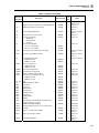
8-1.
Spurious Content Test ...............................................................................................
Phase Noise Test (9640A only).................................................................................
Phase Noise Test (9640A-LPN only)........................................................................
AM Rate Test ............................................................................................................
AM Depth Test..........................................................................................................
FM Rate Test.............................................................................................................
FM Deviation Test ....................................................................................................
Level Accuracy Test, 50 Ω (High)............................................................................
Level Accuracy Test (50 Ω), High Frequency Test Points, Thermal Power Sensor.
Level Accuracy Test (50 Ω), High Frequency Test Points, Diode Power Sensor ....
Level Accuracy Test (50 ), Low Level Test Points..................................................
Optional Ultra-Low Level Accuracy Test (50 Ω) Points ..........................................
Attenuation Accuracy (50 Ω)....................................................................................
VSWR Test (50 Ω)....................................................................................................
Level Accuracy Test (75 Ω), Low Frequency Test Points........................................
Level Accuracy Test (75 Ω), High Frequency Test Points .......................................
Level Accuracy Test (75 Ω), Low Level Test Points................................................
Optional Ultra-Low Level Accuracy Test (75 Ω) Points ..........................................
VSWR Test (75 Ω )...................................................................................................
Descriptions of the Rows in a Test Failure Display..................................................
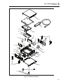
9640A Final Assembly..............................................................................................
x
5-11
5-13
5-14
5-15
5-16
5-16
5-17
5-20
5-22
5-24
5-26
5-29
5-31
5-34
5-37
5-39
5-42
5-45
5-50
7-22
8-5
List of Figures
Figure
Title
Page
1-1. 9640A RF Reference Source.................................................................................
2-1. Accessing the Fuse and Changing Line Voltage...................................................
3-1. Front Panel Controls, Indicators, and Connectors.................................................
3-2. Status Bar ..............................................................................................................
3-3. Control Screens for the RF Output Signal ............................................................
3-4. Rear Panel Controls and Connectors.....................................................................
3-5. Connecting the Leveling Head..............................................................................
3-6. Control Screens for the RF Output Signal ............................................................
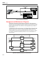
4B-1. Vertical Compatibility...........................................................................................
4B-2. Horizontal Compatibility ......................................................................................
4B-3. Overview of the Firmware in a SCPI Instrument..................................................
4B-4. Program and Response Messages .........................................................................
4B-5. Syntax of a Program Message Unit.......................................................................
4B-6. Syntax of a Terminated Program Message ...........................................................
4B-7. Example of a Terminated Program Message ........................................................
4B-8. The SCPI Command Tree .....................................................................................
4B-9. Syntax of a Response Message Unit .....................................................................
4B-10. Syntax of a Terminated Response Message..........................................................
4B-11. Example of the TRIGger Subsystem Command Tree...........................................
4B-12. Instrument Status Register Structure.....................................................................
4B-13. Structural Overview of the Status Event Register.................................................
4B-14. Bits in the Standard Event Status Register............................................................
4C-1. Bus Command without Coupling..........................................................................
4C-2. Bus Command with Coupling...............................................................................
4F-1.
8662 GPIB Preferences Screen ...........................................................................
5-1. Equipment Connections - Reference Frequency Accuracy Test...........................
5-2. Equipment Connections - Frequency Accuracy Test ............................................
5-3. Equipment Connections - Harmonics and Spurious Content Test ........................
5-4. Equipment Connections - Level Accuracy Tests (50 Ω), Low Frequency Points
5-5. Level Accuracy Tests (50 Ω), High Frequency Points .........................................
5-6. Level Accuracy Tests (50 Ω), Low Level Points..................................................
5-7. Equipment Connections - Attenuation Accuracy Test (50 Ω) ..............................
5-8. Equipment Connections - VSWR Test (50 Ω)......................................................
5-9. Equipment Connections - Level Accuracy Tests (75 Ω), Low Frequency Points
5-10. Equipment Connections- Level Accuracy Tests (75 Ω), High Frequency Points.
1-7
2-7
3-3
3-8
3-12
3-21
3-32
3-36
4B-3
4B-4
4B-4
4B-7
4B-8
4B-8
4B-8
4B-9
4B-10
4B-10
4B-11
4B-15
4B-21
4B-21
4C-23
4C-24
4F-4
5-6
5-7
5-10
5-19
5-21
5-25
5-30
5-32
5-36
5-38
xi
9640A
Instruction Manual
5-11.
5-12.
5-13.
6-1.
6-2.
6-3.
6-4.
7-1.
7-2.
7-3.
7-4.
7-5.
7-6.
7-7.
7-8.
7-9.
8-1.
8-2.
8-3.
Equipment Connections- Level Accuracy Tests (75 Ω), Low Level Points .........
Equipment Connections - Attenuation Accuracy Test (75 Ω) ..............................
Equipment Connections - VSWR Test (75 Ω)......................................................
9640A Overall Functional Block Diagram ...........................................................
A1 Synthesizer PCA - Simplified Schematic Diagram.........................................
A2 RF Output PCA - Simplified Schematic Diagram ..........................................
A9 Leveling Head Assembly - Simplified Block Diagram...................................
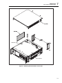
Removing External Hardware and Shields ...........................................................
Removing the A2 RF Output PCA........................................................................
Removing the A6 Front Panel Assembly..............................................................
Removing the A3 Digital PCA .............................................................................
Removing the A1 Synthesizer PCA ......................................................................
Removing the Fans................................................................................................
Removing the Rear Panel......................................................................................
Removing A4 Power Supply PCA........................................................................
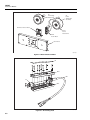
Exploded View of the A9 Leveling Head .............................................................
9640A Final Assembly..........................................................................................
Rear Panel Assemblies..........................................................................................
A9 Leveling Head .................................................................................................
xii
5-40
5-46
5-49
6-4
6-8
6-9
6-10
7-7
7-8
7-10
7-11
7-12
7-13
7-14
7-16
7-17
8-7
8-8
8-8
Chapter 1
Introduction and Specifications
Title
About the Manual ................................................................................................
Safety Information ...............................................................................................
General Safety Summary.................................................................................
Symbols ...........................................................................................................
Product Description .............................................................................................
Options and Accessories ......................................................................................
Specifications.......................................................................................................
General Specifications.....................................................................................
Frequency Reference Input/Output Specifications..........................................
Leveled Sine Specifications.............................................................................
Modulation Specifications...............................................................................
Frequency Sweep Specifications .....................................................................
GPIB Command Emulation Mode Specifications...........................................
Page
1-3
1-3
1-3
1-6
1-7
1-8
1-9
1-9
1-10
1-10
1-14
1-17
1-17
1-1
9640A
Instruction Manual
1-2
Introduction and Specifications
About the Manual
1
About the Manual
This is the Instruction Manual for the 9640A RF Reference Source (hereafter referred to
as the Instrument) and its options and accessories. It contains all of the information a user
will need to operate and maintain the Instrument effectively. The manual is divided into
the following chapters:
Chapter 1
Chapter 2
Chapter 3
Chapter 4
Chapter 5
Chapter 6
Chapter 7
Chapter 8
Appendix A
Introduction and Specifications
Preparing the Instrument for Operation
Local Operation
Remote Operation
Calibration
Theory of Operation
Maintenance
Lists of Replaceable Parts
Rack mounting instructions
Appendix B
Error Messages
Safety Information
This section addresses safety considerations and describes symbols that may appear
either in this manual or on the Instrument.
A XW Warning statement identifies conditions or practices that could result in injury or
death.
A W Caution statement identifies conditions or practices that could result in damage to
the Instrument or equipment to which it is connected.
XW Warning
To avoid electric shock, personal injury, or death, carefully read
the information under General Safety Summary before
attempting to install, use, or service the Instrument.
General Safety Summary
The Instrument has been designed and tested in accordance with the European standard
publication EN 61010-1: 2001 and U.S. / Canadian standard publications UL 610101:2004 and CAN/CSA-C22.2 No.61010-1:2004. The Instrument left the factory in a safe
condition.
This manual contains information and warnings that must be observed to keep the
Instrument in a safe condition and ensure safe operation. Using or servicing the
Instrument in conditions other than as specified in the Instruction Manual could
compromise your safety.
To use the Instrument correctly and safely, read and follow the precautions on the next
few pages, as well as, the safety instructions or warnings given throughout this manual.
In addition, follow all generally accepted safety practices and procedures when working
with and around electricity.
1-3
9640A
Instruction Manual
Safety Information
XW Warning
To avoid electric shock, personal injury, fire, or death, read the following warnings before
using the Instrument:
• Use the Instrument only as specified in this manual, or the protection provided by the
instrument might be impaired.
• Do not use the Instrument in wet environments.
• Inspect the Instrument before using it. Do not use the Instrument if it appears damaged.
• Do not use the Instrument if it operates abnormally. Protection may be impaired. If in
doubt, have the Instrument serviced.
• Have the Instrument serviced only by qualified service personnel.
• Always use the power cord and connector appropriate for the voltage and outlet of the
country or location in which you are working.
• Connect the Instrument power cord to a power receptacle with an earth ground. A
protective ground connection by way of the grounding conductor in the power cord is
essential for safe operation.
• Never remove the cover or open the case of an instrument without first disconnecting the
Instrument from the power source.
• Never operate the Instrument with the cover removed or the case open.
• Use caution when working with voltages above 30 V ac rms, 42 V ac peak, or 42 V dc.
These voltages pose a shock hazard.
• Use only the replacement fuse(s) specified by the manual.
• When servicing the Instrument, use only specified replacement parts.
XW Warning
To prevent personal injury, use good lifting practices when lifting or moving the
Instrument. The Instrument is an unbalanced load and can weigh as much as 18 kg
(40 pounds).
XW Warning
To prevent the transmission of an RF signal, never connect the Instrument output
(the output from a passive Leveling Head) to a radiating antenna or leaky
transmission line of any kind. Such a transmission could be hazardous to
personnel and may impair the SAFE operation of equipment, and communication
and navigation systems.
The connection of a radiating antenna is an illegal act in many countries. Only
connect the Instrument output (the output from a passive Leveling Head) to
equipment or transmission lines designed to prevent RF leakage at the level and
frequency of the Instrument output.
1-4
Introduction and Specifications
Safety Information
1
Avoiding Instrument Damage
W Caution
To avoid damage to the instrument, read the following cautions
before using the instrument:
•
The front panel connectors on the Instrument are suited only for use with
Fluke 9640A-xx Leveling Heads. No other connection is permitted.
•
The Leveling Heads are fitted with close tolerance metrology grade
N-connectors compliant with MIL-C-39012 and MMC Standards for
Precision N-connectors. When used in demanding metrology
applications the Leveling Heads are likely to be mated with similar
high-quality connectors, thus, minimizing the opportunity for wear
and damage. However, in applications that require frequent mating
or mating to lower quality connectors, the opportunity for
damaging the connectors increases. On these high-risk occasions,
consider using a sacrificial adapter to prevent damage to the N
connectors.
•
Improper mating of 50 Ω and 75 Ω connectors will irreversible
damage the center pin. Although appearance is similar, the
dimensions (pin diameter) of 75 Ω differ significantly from those of
50 Ω. Make sure that the 50 Ω Leveling Head is mated only to 50 Ω
systems and, likewise, that the 75 Ω Leveling Head is mated only
with 75 Ω systems. Otherwise, mechanical damage of metrologygrade connectors and out-of-tolerance performance is likely to
occur.
•
Very high-grade flexible coaxial transmission line conducts the RF
input signal to 9640A-xx Leveling Heads. As with any coaxial line,
deformation of sidewalls or abrupt bending can degrade
performance. Take care to avoid mechanical stress or tight bend
radius < 60 mm (2.4 in).
•
Reliable and repeatable interconnections are achieved only at
specified torque settings. Performance will be impaired if torque
settings are not observed, and permanent connector damage is
likely to result from over-tightening.
•
Critical connector mating dimensions could be damaged during
disassembly of a Leveling Head. DO NOT TAMPER with the four
mounting screws at the base of the N-Connector. Leveling Head
disassembly should only be performed by qualified service
personnel at a Fluke Service Center.
•
To prevent damage to the instrument, do not use aromatic
hydrocarbons or chlorinated solvents for cleaning.
1-5
9640A
Instruction Manual
Symbols
The following safety and electrical symbols may appear on the Instrument or in this
manual.
W
Risk of danger.
J
Earth ground.
Important information. See manual.
X
Hazardous voltage. Voltage > 30 V dc or
ac peak might be present
.
Protective conductor terminal
B
AC (Alternating Current).
E
Capacitance.
F
DC (Direct Current).
G
Diode.
I
Fuse.
CAT
IEC 61010 Overvoltage (installation or
measurement) Category.
<
Recycle.
D
or
AC or DC (Alternating or Direct Current)
C
Y
h
!
1-6
Potentially hazardous voltage.
Static awareness. Static discharge can
damage part(s).
Power ON / OFF
~
Do not dispose of this product as unsorted
municipal waste. Go to Fluke’s website for recycling
information.
Introduction and Specifications
Product Description
1
Product Description
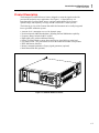
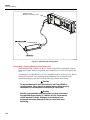
The Instrument is an RF Reference Source designed to create the signals needed for
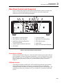
precision RF and microwave applications. See Figure 1-1. Signal delivery via
interchangeable Leveling Heads ensures a unique combination of level accuracy,
dynamic range, and frequency coverage in both 50 Ohm and 75 Ohm systems.
The following is a list of the features that enable the Instrument to be readily integrated
into a typical RF calibration system:
•
•
•
•
•
•
•
•
•
Accurate level / attenuation over a wide dynamic range
Precision internal AM/FM modulation, including External Modulation capability
Frequency Range includes both LF and RF
High signal purity with no additional filtering
Passive Leveling Heads to ensure direct and precise signal delivery to the load
Low Phase Noise – two performance levels in the 9640A and 9640A-LPN products
IEEE 488 Remote Interface
Remote command emulation of legacy signal generators (optional)
Rack Mount Slide Kit (optional)
ead316f.eps
Figure 1-1. 9640A RF Reference Source
1-7
9640A
Instruction Manual
Options and Accessories
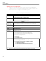
Table 1-1 provides a list of the products, options and accessories available. When
ordering an option or accessory after the original purchase, include a reference to the
Instrument as well as the description from the following table.
Table 1-1. List of Options and Accessories
Products
9640A 4 GHz RF Reference Source with 50 Ω Leveling Head
9640A-STD
(GPIB Command Emulation of HP3335 included)
9640A 4GHz Low Phase Noise RF Reference Source with 50 Ω Leveling Head
9640A-LPN
(GPIB Command Emulation of HP3335 included)
Options
Above supplied with or upgrade to add a 9640A-75 75 Ω Leveling Head
9640A-xxx/75
9640A/75UPG
[1]
8662/8663 GPIB [2]
HP8662A / HP8663A GPIB command emulation
Accessories
Y9600
Rack Mount Slide Kit
9600CASE
Rugged Transit Case
9600CONN
RF Interconnect Kit. The kit includes:
1 – Sacrificial N-Connector, Male to Female Adapter, 50 Ω
1 – Precision N-Connector, Female to Female Adapter, 50 Ω
2 – RF Connector Torque Wrenches
1 – N-Connector
1 – PC3.5/SMA Connector
9640A Manual Set
9640A Instruction Manual Package. The package includes:
1 – Printed Getting Started Manual
1 – CD containing the entire manual set (PDF files), including:
1 – 9640A Instruction Manual
2 – 9640A Getting Started Manuals (English and French)
1 – Tables of 9640A Calibration Points to assist automation of 9640A
adjustment
1-8
[1]
This is a factory/service upgrade that requires the return of the main unit and all of the partner Leveling Heads
[2]
This option is provided for a trial period, therafter requires the purchase and entry of a licence key
Introduction and Specifications
Specifications
1
Specifications
General Specifications
Performance
All specifications apply to a 1 year calibration interval at an ambient temperature
of Tcal ±5 °C.
Nominal factory Tcal calibration temperature 23 °C.
Standard Interfaces
IEEE488.2 (GPIB)
Warmup Time
60 minutes
Temperature
Operating:
Specified Operation:
Storage:
Relative Humidity
Operating or Storage:
Non-condensing, 5 °C to 30 °C <95 %, <40 °C <75 %, <50 °C <45 %
Altitude
Operating: ≤2,000 m
Non-operating: ≤12,000 m
Safety
EN 61010-1:2001, CAN/CSA 22.2 No 61010-1:2004 and UL 61010-1:2004,
indoor use only, pollution degree 2, installation category II.
EMC
EN 61326:2006 Class B.
Line Power
Rating: 115 V/ 230V nominal
Power Consumption
≤250 VA
Dimensions
433 mm (17.0”) wide, 146 mm (5.8”) high and 533 mm (21.0”) deep. Mounts
within industry-standard 19” (483 mm) rack-mount frames when fitted with Y9600
rack mounting kit.
Weight
18 kg (40 lbs)
[1]
Type tested for operation and functionality 90 to 132 V rms and 180 to 264 V rms at 47 to 63 Hz.
533 mm (21.0")
146 mm
(5.8")
433 mm (17.0")
133 mm
(5.24")
[1]
0 °C to 50 °C
5 °C to 40 °C
-20 °C to +70 °C
9640A Dimensions
1-9
9640A
Instruction Manual
Frequency Reference Input/Output Specifications
Frequency Reference Input
Rear panel Reference Frequency Input BNC connector
Frequency
9640A:
1 MHz to 20 MHz in 1 MHz steps ±30 ppm
9640A-LPN: 1 MHz to 20 MHz in 1 MHz steps ±1 ppm
Level
1 V pk nominal into 50 Ω, ±5 V pk max.
Frequency Reference Output
Rear panel Reference Frequency Output BNC connector
Frequency
1 MHz or 10 MHz, user selectable
Level
1.5 V pk-pk into 50 Ω, 3 V pk-pk into 1 kΩ, TTL compatible.
Accuracy
[1]
Ageing Rate and Stability
[1]
0.04 ppm
[1]
-9
After 24hr warmup: 2x10 /day.
-8
-8
Continuous operation: ≤ 2x10 /month, ≤ 4x10 over 1 year.
Specifications apply only if Internal Frequency Reference operation selected. With External Frequency Reference operation
selected the frequency of the Frequency Reference Output is locked to the signal applied to the Frequency Reference Input.
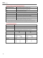
Leveled Sine Specifications
Frequency
Range
10 Hz to 4 GHz
Resolution
<100 MHz: 0.001 Hz , >100 MHz: 11 digits
Accuracy
Internal Frequency Reference: 0.04 ppm + 0.16 mHz
External Frequency Reference: Ext Freq Ref Accuracy + 0.16 mHz
50 Ω output
Amplitude
1-10
75 Ω output
Output Connector
Precision 50 Ω N-Series male
Precision 75 Ω N-Series male
Range
-130 dBm to +24 dBm
(0.2 uV to 10 V pk-pk)
>125 MHz:
+20 dBm
>1.4 GHz:
+14 dBm
-130 dBm to +18 dBm
(0.13 uV to 6.3 V pk-pk)
>125 MHz:
+14 dBm
>1.4 GHz:
+8 dBm
Resolution
0.001dB
0.001dB
VSWR
≤500 MHz:
≤1 GHz:
≤3 GHz:
≤4 GHz:
≤1.1
≤1.2
≤1.3
≤1.4
≤500 MHz:
≤1 GHz:
≤2 GHz:
≤1.1
≤1.2
≤1.3
Introduction and Specifications
Specifications
50 Ω output
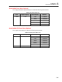
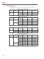
Attenuation
Attenuation
[1]
100 kHz to 128 MHz
1
75 Ω output
Relative to +16 dBm output
Relative to +10 dBm output
0 - 33 dB
33 - 64 dB
64 - 100 dB
[1]
100 - 116 dB
0 - 33 dB
33 - 64 dB
64 - 100 dB
[1]
100 - 110 dB
±0.035 dB
±0.04 dB
±0.1 dB
±0.2 dB
±0.035 dB
±0.05 dB
±0.15 dB
±0.3 dB
Cumulative and Incremental
Attenuation (Typical)
Relative to any level between +16dBm
and -100 dBm, 100 kHz to 128 MHz
Relative to any level between +10dBm and
-100 dBm, 100 kHz to 128 MHz
To determine the attenuation
specification between any two
[2]
output levels, apply an RSS
summation of the dB values
listed for each output level .
+16 to -17 dBm
-17 to -48 dBm
-48 to -84 dBm
-84 to -100 dBm
+10 to -23 dBm
-23 to -54 dBm
-54 to -90 dBm
-90 to -100 dBm
±0.035 dB
±0.04 dB
±0.1 dB
±0.2 dB
±0.035 dB
±0.05 dB
±0.15 dB
±0.3 dB
[1]
Specifications are typical below 10 MHz at all attenuations, and typical for attenuation greater than 100 dB at all frequencies.
[2]
Root Sum Square.
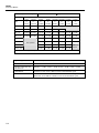
50 Ω Output
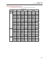
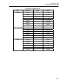
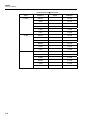
Absolute Amplitude Accuracy
Amplitude
dBm
10 Hz
to
20 kHz
>20 kHz
to
<100 kHz
100 kHz
to
<10 MHz
10 MHz >125 MHz >300 MHz >1.4 GHz
to
to
to
to
125 MHz 300 MHz 1.4 GHz
3 GHz
>+20 to +24
±0.05 dB
±0.05 dB
±0.05 dB
±0.05 dB
>+14 to +20
±0.05 dB
±0.05 dB
±0.05 dB
±0.05 dB
±0.1 dB
±0.25 dB
-17 to +14
±0.05 dB
±0.05 dB
±0.05 dB
±0.05 dB
±0.1 dB
±0.25 dB
±0.3 dB
±0.5 dB
-48 to <-17
±0.05 dB
±0.05 dB
±0.05 dB
±0.05 dB
±0.1 dB
±0.5 dB
±0.5 dB
±0.5 dB
±0.2 dB
±0.2 dB
±0.2 dB
±0.5 dB
±0.5 dB
±0.5 dB
±0.5 dB
±0.5 dB
±0.5 dB
±1.0 dB
±1.0 dB
±1.0 dB
>-94 to -84
±0.5 dB
±0.5 dB
±0.5 dB
±1.0 dB
±1.0 dB
-130 to -94
±1.5 dB
±1.5 dB
±1.5 dB
±1.5 dB
±1.5 dB
Not
Spec’d
>-74 to <-48
>-84 to -74
>3 GHz
to
4 GHz
Output not available
Not Specified
1-11
9640A
Instruction Manual
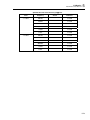
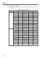
75 Ω Output
Absolute Amplitude Accuracy
Amplitude
[1]
>3 GHz
to
4 GHz
dBm
10 Hz
to
20 kHz
>20 kHz
to
<100 kHz
100 kHz
to
<10 MHz
10 MHz >125 MHz >300 MHz >1.4 GHz
to
to
to
to
3 GHz
125 MHz 300 MHz 1.4 GHz
>+14 to +18
±0.06 dB
±0.06 dB
±0.06 dB
±0.06 dB
>+8 to +14
±0.06 dB
±0.06 dB
±0.06 dB
±0.06 dB
±0.15 dB ±0.25 dB
-23 to +8
±0.06 dB
±0.06 dB
±0.06 dB
±0.06 dB
±0.15 dB ±0.25 dB
±0.3 dB
±0.5 dB
-54 to <-23
±0.15 dB
±0.15 dB
±0.15 dB
±0.15 dB
±0.15 dB ±0.5 dB
±0.5 dB
±0.5 dB
±0.2 dB
±0.2 dB
±0.2 dB
±0.5 dB
±0.5 dB
±0.5 dB
±0.7 dB
±0.7 dB
±0.7 dB
±1.0 dB
±1.0 dB
±1.0 dB
>-100 to -90
±0.7 dB
±0.7 dB
±0.7 dB
±1.0 dB
±1.0 dB
-120 to -100
±1.5 dB
±1.5 dB
±1.5 dB
±1.5 dB
±1.5 dB
Not
Spec’d
>-80 to <-54
>-90 to -80
[1]
Output not available
Not Specified
[1]
1-12
Specifications are typical for frequencies >2 GHz
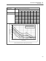
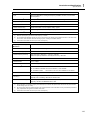
Signal Purity
At maximum output level
Harmonics
≤ 1 GHz: < -60 dBc, >1 GHz: < -55 dBc
Spurious ≥3 kHz offset and
Sub-harmonics
≤500 MHz: < -75 dBc, ≤1 GHz: < -70 dBc, ≤2 GHz: < -65 dBc, ≤4 GHz: < -60 dBc
SSB AM Noise
10 MHz to 1.4 GHz, <0.015 % RMS, in 50 Hz to 3 kHz Bandwidth, typical.
Residual FM
9640A:
<0.5 Hz RMS at <125 MHz, in 50 Hz to 3 kHz Bandwidth, typical.
9640A-LPN: <0.4 Hz RMS at <125 MHz, in 50 Hz to 3 kHz Bandwidth, typical.
Introduction and Specifications
Specifications
SSB Phase Noise
1
At maximum output level, Internal Freq Ref, (dBc/Hz)
Frequency
Offset from Carrier
10Hz
Spec (Typ)
100Hz
Spec (Typ)
1kHz
Spec (Typ)
10kHz
Spec (Typ)
100kHz
Spec (Typ)
1MHz
Spec (Typ)
10MHz
Spec (Typ)
9640A
1GHz
Not Spec’d
Not Spec’d
-97 (-102)
-118 (-122)
-118 (-122)
-124 (-130)
-142 (-144)
9640A-LPN
10MHz
-104 (-108)
-129 (-139)
-148 (-155)
-151 (-155)
-153 (-157)
-155 (-157)
-155 (-160)
125MHz
-92 (-95)
-117 (-124)
-140 (-145)
-144 (-149)
-147 (-152)
-153 (-154)
-153 (-156)
250MHz
-86 (-90)
-112 (-118)
-135 (-140)
-141 (-146)
-142 (-149)
-152 (-155)
-153 (-155)
500MHz
-80 (-85)
-107 (-112)
-130 (-136)
-138 (-143)
-139 (-144)
-151 (-154)
-153 (-154)
1GHz
-74 (-78)
-101 (-106)
-125 (-130)
-134 (-138)
-134 (-138)
-148 (-152)
-151 (-153)
2GHz
-68 (-71)
-95 (-100)
-119 (-126)
-129 (-133)
-128 (-133)
-145 (-149)
-150 (-152)
4GHz
-62 (-68)
-89 (-96)
-114 (-120)
-124 (-128)
-122 (-128)
-141 (-146)
-149 (-151)
-60
9640A-LPN Phase Noise measured
with Rohde & Schwarz FSUP Signal
Source Analyser, plotted without spurs.
-70
-80
Phase Noise (dBc/Hz)
-90
-100
-110
4GHz
-120
-130
1GHz
-140
-150
125MHz
-160
-170
10
10Hz
500MHz
10MHz
100
100Hz
1000
1kHz
10000
10kHz
100000
100kHz
1000000
1MHz
10000000
10MHz
Offset Frequency
9640A-LPN SSB Phase Noise at +10dBm output level (measured).
1-13
9640A
Instruction Manual
External Leveling Input
Rear panel Modulation, Leveling and Frequency Pull BNC connector, 10 kΩ
nominal input impedance.
For external power meter leveling
User adjustable full scale voltage , 1 V to 5 V, positive polarity.
Maximum Input
±5 V
External Frequency Control Input
Rear panel Modulation, Leveling and Frequency Pull BNC connector, 10 kΩ
nominal input impedance.
Frequency Pull Range
±5 ppm
Frequency Pull Sensitivity
User adjustable between 0.0001 ppm/V to 1.0000 ppm/V, positive or negative
polarity.
Maximum Input
±5 V
Modulation Specifications
50 Ω output
Amplitude Modulation
Waveform
Sinusoidal, Triangle, or External signal
Carrier Frequency
50 kHz to 4 GHz
Carrier Level
<1.4 GHz: ≤+14 dBm
>1.4 GHz: ≤+8 dBm
Carrier Level Accuracy
[1]
<1.4 GHz: ≤+8 dBm
>1.4 GHz: ≤+2 dBm
As Leveled Sine + 0.5 dB, typical
Carrier Harmonics
≤ 50 dBc typical
Rate
≤125.75 MHz, 1 Hz to 220 kHz, ≤ 1 % of Carrier Frequency.
>127.75 MHz, 1 Hz to 100 kHz
Rate Resolution
0.1 Hz, 5 digits
Rate Accuracy
≥1 kHz: ±1 digit, <1 kHz: ±10 mHz
Depth
0.1 % to 99 %
Depth Resolution
0.1 %
Carrier Frequency and Level
Range for Specified Depth
Accuracy and Distortion
≤1 GHz, -56 dBm to +14 dBm
AM Sine Depth Accuracy
AM Sine Distortion
1-14
75 Ω output
[2] [3]
[2]
≤1 GHz, -62 dBm to +8 dBm
3 % of setting + 0.1 %, for >5 % depth.
Typically 0.75 % of setting + 0.1 %, for 10 % to 90 % depth, ≤75 MHz carrier frequency.
≤ -40 dBc,10 % to 80 % depth, for ≤ 20 kHz rate, or for > 20 kHz rate at ≤75 MHz carrier
frequency.
Typically ≤ -50 dBc, 10 % to 80 % depth, ≤75 MHz carrier frequency.
[1]
Signal content at carrier frequency only, excluding sidebands.
[2]
Specifications are typical for modulation rates <20Hz.
[3]
Includes harmonic distortion and noise up to 5 times rate frequency.
Introduction and Specifications
Specifications
1
AM External
Input
Rear panel Modulation, Leveling and Frequency Pull BNC connector, 10 kΩ nominal
input impedance.
Bandwidth (-3 dB)
[1]
[2]
DC coupled : DC to 220 kHz , AC coupled: 10 Hz to 220 kHz, typical.
Depth Sensitivity
User adjustable, 0.5 %/V to 400 %/V
Input Level
±2 V pk maximum operating, ±5 V pk absolute maximum
Carrier Level Accuracy
As AM Internal Sine + 20 mV x depth/V setting. Typical.
Depth Accuracy
3 % of setting + 0.1 %, for >5 % depth, 1 Vpk input, DC or 200 Hz to 20 kHz.
Residual Distortion
[3]
As AM Internal Sine, for 1 Vpk input, ≤100 kHz.
[1]
Maximum input frequency 100 kHz for carrier frequency >125 MHz.
[2]
DC coupled External Modulation permits DC control of carrier level or the offsetting of the modulation waveform. Note that at rates
from 0.5 Hz to 10 Hz interaction with carrier leveling may occur, resulting in modulation distortion.
[3]
Includes harmonic distortion and noise up to 5 times rate frequency.
Frequency and Phase
Modulation
[1]
Waveform
FM: Sinusoidal, or External signal. PM: Sinusoidal only.
Carrier Frequency (Fc)
9 MHz to 4 GHz
Carrier Frequency Accuracy
Internal Frequency Reference: 0.04 ppm + 240 mHz
External Frequency Reference: Ext Freq Ref Accuracy + 240 mHz
Rate (Fr)
1 Hz to 300 kHz
Rate Resolution
0.1 Hz, 5 digits
Rate Accuracy
≥1 kHz: ±1 digit, <1 kHz: ±10 mHz
Deviation (Fd)
[2]
Fc 9 MHz to 31.25 MHz:
FM: 10Hz to 300 kHz, PM: ≤1000rad
Fc 31.25 MHz to 125 MHz: FM: 10 Hz to 750 kHz, PM: ≤1000rad
Fc 125 MHz to 4 GHz:
FM: 10 Hz to 0.12 % Fc, PM: ≤1000rad or 0.12 %Fc/Fr
Deviation Resolution
FM: 0.1 Hz, 5 digits. PM: 0.0001rad, 5 digits
FM/PM Sine Deviation
[2]
Accuracy
3 % of setting + 240 mHz.
Typically 0.25 % of setting + 240 mHz, for ≤50 kHz rate.
FM/PM Sine Distortion
[2] [3]
≤ -40 dBc (1 %) +20 dB/decade above 10 kHz (See chart).
Typically ≤ -65 dBc +20 dB/decade above 1 kHz.
[1]
Phase modulation is generated by applying sinusoidal frequency modulation with peak deviation derived from the phase deviation
and rate settings (Fd = φd x Frate).
[2]
See chart showing maximum available deviation, and maximum deviation for which deviation accuracy and distortion specifications
apply. Specifications are typical for modulation rates <20Hz.
[3]
Includes harmonic distortion and noise up to 5 times rate frequency.
1-15
9640A
Instruction Manual
FM & PM Distortion
FM Deviation Limits and Performance Specifications
Distortion
(dBc)
Deviation
(Fd)
4.8 MHz
Max Available Deviation
-20
750 kHz
300 kHz
-30
220 kHz
180 kHz
150 kHz
-40
66 kHz
-50
Performance Specifications Applicable
10 Hz
1
9 MHz 11 MHz
31.25 MHz
125 MHz
10
100
4 GHz
ead40f.eps
300
Rate (kHz)
ead41.eps
FM External
1-16
Input
Rear panel Modulation Leveling and Frequency Pull BNC connector, 10 kΩ nominal
input impedance.
Bandwidth (-3 dB)
DC coupled: DC to 300 kHz , AC coupled: 10 Hz to 300 kHz. Typical.
Deviation Sensitivity
User adjustable, 500 Hz/V to 19 MHz/V, carrier frequency dependent.
Input Level
±2 V pk maximum operating, ±5 V pk absolute maximum
Carrier Frequency Accuracy
As FM Internal Sine + 20 mV x deviation/V setting, typical.
Deviation Accuracy
[1]
3 % of setting + 240 mHz, for 1 Vpk input, DC or 200 Hz to 20 kHz rate, deviation
>0.01 %Fc.
Residual Distortion
[1] [2]
As FM Internal Sine, for 1 Vpk input, deviation >0.01 %Fc.
Typically ≤ -55 dBc +20 dB/decade above 10 kHz, for 1 Vpk input, deviation >0.01 % Fc.
[1]
See chart showing maximum available deviation, and maximum deviation for which deviation accuracy and residual distortion
specifications apply.
[2]
Includes harmonic distortion and noise up to 5 times rate frequency.
Modulation Trigger Output
Rear panel Trigger I/O BNC connector
Level
TTL compatible logic output, selectable as rising or falling edge
Timing Alignment
±500 ns typical, from modulation waveform zero crossing for Sinusoidal or
positive peak for Triangle.
Introduction and Specifications
Specifications
1
Frequency Sweep Specifications
Sweep Frequency Range
10 Hz to 4 GHz
Sweeps are generated as a sequence of discrete synthesized frequencies.
Sweep Modes
Stop - Start and Center - Span
Linear or Logarithmic
Repetitive, Single Shot, triggered and Manual Sweep
Squelch or Non Squelch at frequency transitions
Frequency Resolution
<100 MHz: 0.1 Hz , >100 MHz: 11 digits
Frequency Steps
5 million maximum.
Step Size
0.1 Hz to 4 GHz
Step Dwell Time
20 ms to 10 s
Sweep Duration
100 hrs maximum, calculated from Step Dwell x Number of Steps
Squelch Duration
[1]
20 ms, or 35 ms maximum during range transition
Trigger Input/Sync Output
Rear panel Trigger I/O BNC connector, selectable as sweep trigger input or
sweep sync output.
Trigger Input
TTL compatible logic input, selectable as rising or falling trigger to start sweep.
Typically ≤1 ms delay from trigger to sweep start.
Sync Output
TTL compatible logic output, selectable as rising or falling sync pulse coincident
with sweep start.
Typical pulse duration 250 μs. Typical time alignment +14 to +16 ms from sweep
start (delay ensures settled signal at the trigger point).
[1]
When selected, Squelch is active between all frequency transitions. When deselected, Squelch is active only at hardware range
boundaries.
GPIB Command Emulation Mode Specifications
9640A
HP3335A
9640A-LPN
9640A-LPN + Option 8662/8663 GPIB
HP3335A
[1]
HP3335A, HP8662A, HP8663A
[1]
Only one instrument emulation mode may be selected at any one time.
1-17
9640A
Instruction Manual
1-18
Chapter 2
Preparing the Instrument for Operation
Title
Introduction..........................................................................................................
Contacting Fluke..................................................................................................
Unpacking and Inspection ...................................................................................
Storing and Shipping the Instrument ...................................................................
Power Considerations ..........................................................................................
Replacing the Power Cord...............................................................................
Replacing the Line-Power Fuses .....................................................................
Selecting Line Voltage ....................................................................................
Power-On Sequence.............................................................................................
Power-On Self Test .........................................................................................
Power-On State................................................................................................
Leveling Head Connections.................................................................................
Installing the Instrument in an Equipment Rack..................................................
Cooling Considerations........................................................................................
Cleaning the Instrument.......................................................................................
Page
2-3
2-3
2-3
2-4
2-5
2-5
2-6
2-6
2-8
2-8
2-9
2-10
2-10
2-10
2-10
2-1
9640A
Instruction Manual
2-2
Preparing the Instrument for Operation
Introduction
2
Introduction
This chapter contains instructions for unpacking the Instrument and preparing it for
operation. Many of the procedures in this chapter are also useful for performing general
maintenance on the Instrument. They include the following:
•
•
•
•
Changing line voltage (115 V ac to 230 V ac)
Replacing the line-power fuse
Connecting and powering the Instrument
Cleaning and storing the Instrument
Contacting Fluke
To contact Fluke for product information, operating assistance, service, and to get the
location of the nearest Fluke distributor or Service Center, call:
1-888-99FLUKE (1-888-993-5853) in U.S.A.
1-800-36-FLUKE (1-800-363-5853) in Canada
+31-402-675-200 in Europe
+81-3-3434-0181 Japan
+65-738-5655 Singapore
+1-425-446-5500 from other countries
Visit Fluke's web site at: http://www.fluke.com.
Unpacking and Inspection
W Warning
To prevent personal injury, use good lifting practices when
lifting or moving the Instrument. The Instrument is an
unbalanced load and weighs up to 18 kg (40 pounds).
Fluke has taken great care to ensure that the Instrument arrives in perfect condition.
When the Instrument arrives, carefully unpack and inspect for external damage to the
case, front panel, and rear panel. If the Instrument has been subject to rough handling in
transit, there may be evidence of external damage to the shipping carton. Check also to
make sure all standard items listed in Table 2-1 are present.
If the Instrument or the shipping container have been damaged, notify the carrier
immediately. Report any shortages to the place of purchase or to the nearest Fluke
Technical Service Center.
If the shipping container and the packing material are undamaged, save them for use as a
future storage/shipping container for the Instrument.
2-3
9640A
Instruction Manual
Table 2-1. List of Contents
Description
Quantity
9640A RF Reference Source
1
9640A-50 Leveling Head
1
9640A-75 Leveling Head
Optional
Carrying/Storage Case (for two Leveling Heads and the 9600CONN RF
Interconnect Kit )
1
9640A Getting Started Manual, English
1
CD ROM – Manual Set
1
Line Cord
1
Certificate of Calibration
1
Storing and Shipping the Instrument
W Warning
To prevent personal injury, use good lifting practices when
lifting or moving the Instrument. The Instrument is an
unbalanced load and weighs up to 18 kg (40 pounds).
To store the Instrument, place it inside a sealed plastic bag and then place the bagged unit
inside the cushioning material inside the original shipping container. Close and secure the
container. This container is the most suitable storage receptacle for the Instrument
because it provides the necessary shock isolation during normal handling. Store the
boxed Instrument in a location that complies with the storage environment specification.
See Chapter 1, Introduction and Specifications.
Whenever it is necessary to ship the Instrument, use the original shipping container if
possible. Pack and secure the Instrument as described in the previous paragraph. If you
must substitute for the original container, choose a substitute that will provide shock
isolation comparable to the original container. Recommended dimensions for a substitute
cushioned container are given in Table 2-2.
Table 2-2. Dimensions for a Substitute Cushioned Shipping Container
Container
Width
570 mm (22.5 in)
Depth
Box
720 mm (28.5 in)
Corner
> 60 mm (2.4 in) depth of expanded polyethylene (35 kg/m3) at the
instrument corners.
Cushions
2-4
Length
360 mm (14.2 in)
Preparing the Instrument for Operation
Power Considerations
2
Power Considerations
The Instrument ships from the factory configured to match the requirements of your local
ac line power. If the Instrument is relocated to another region it may need to be
reconfigured to match the ac line power of the new location. Three things affect the
configuration:
• Power cord (See Table 2-3.)
• Line-power fuse (See Table 2-4 and Figure 2-1.)
• Rear-panel switch setting (115-230, see Table 2-3 and Figure 2-1.)
The following paragraphs describe how to make the changes for a new voltage
configuration. They are also useful to verify that the Instrument’s current power
configuration is correct.
Replacing the Power Cord
XW Warning
To avoid shock hazard, connect the instrument power cord to a
power receptacle that has an earth ground connection. A
protective ground connection by way of the grounding
conductor in the power cord is essential for safe operation.
The various power cords available for use with the Instrument are listed and shown in
Table 2-3. Use the table to identify your general location and the recommended LC
power cord. Match this LC number to one of the plugs in the drawing, and verify that the
plug on your power cable mates correctly with the local power outlets. If the plug is
incorrect, identify the correct LC number, and order the correct power cable from Fluke
using the part number from Table 2-3.
Table 2-3. Power Cord for Various Regions
Description
Power Cord
Location
Voltage/Current
Part Number
North America
120 V/15 A
LC1
284174
North America
240 V/15 A
LC2
2198736
Universal Euro
220 V/16 A
LC3
769422
United Kingdom
240 V/13A
LC4
769445
Switzerland
220 V/10 A
LC5
769448
China/Australia/New Zealand
240 V/10 A
LC6
658641
India/South Africa
240 V/5 A
LC7
782771
LC1
LC2
LC5
LC3
LC6
LC4
LC7
Ead05f.eps
2-5
9640A
Instruction Manual
Replacing the Line-Power Fuses
XW Warning
To prevent fire hazard or damage to the instrument, verify that
the correct fuses are installed for the selected line-voltage
setting. See Table 2-4 for the correct fuse ratings.
The line-power fuses are located on the power block on the rear panel. The selected linevoltage (115 or 230) shows through a small window toward the bottom of the block. See
Figure 2-1. This instrument has dual fusing with fuses in both the line and neutral
connections. When replacing a blown fuse, replace both fuses to avoid a stressed fuse and
subsequent power interruption. Before trying to access and replace the fuses, verify that
the replacement fuses are appropriate for the selected voltage.
To check or replace the fuses, refer to Figure 2-1, and proceed as follows:
1. Disconnect the Instrument from line power.
2. Remove the fuse compartment by inserting a screwdriver blade in the tab located at
the left side of the fuse compartment. Gently pry until the compartment can be easily
removed.
3. Pull the fuses from the compartment for replacement or inspection.
4. Install good fuses with the correct ratings. See Table 2-4.
5. Reinstall the fuse compartment by pushing it back into place until the tab locks.
Table 2-4. Line-Power Fuse
Line Power
115 V AC
230 V AC
Fuse Action
TH
Time Delay HBC
TH
Time Delay HBC
Fuse Rating
IEC 127
Fluke Part No.
Manufacturer
and Type No.
10 A @ 250 V
2650727
(Quantity 2)
Littelfuse 215010
5 A @ 250 V
2650730
(Quantity 2)
Littelfuse 215005
Selecting Line Voltage
The line-voltage selector is located on the power block on the rear panel. The selected
line-voltage (115 or 230) shows through a small inspection window toward the bottom of
the block. See Figure 2-1. Use Table 2-5 to verify the selection before trying to change it.
Use the following procedure to change the line voltage setting:
1. Disconnect the Instrument from line power.
2. Remove the fuse compartment as described earlier. (See Replacing the Line-Power
Fuse.)
3. Remove the line-voltage selector by griping its indicator tab with a pair of long-nose
pliers and pulling it straight out of its connector.
4. Rotate the line-voltage selector to show the desired voltage, and reinsert into the
power block.
5. Before inserting the fuse compartment back into the power block, inspect and verify
that both fuses are appropriate for the selected voltage.
6. Insert the fuse compartment into the power block, and press firmly to lock its tab.
2-6
Preparing the Instrument for Operation
Power Considerations
2
Table 2-5. Voltage Limits for the 115 and 230 Voltage-Switch Settings
Switch Setting
Line Voltage Limits
115
90 V AC to 132 V AC
230
180 V AC to 264 V AC
SAFETY W ARNING
DISCONNECT PO WER AND SIGNAL LEADS
BEFORE REMO VING COVERS .
FOR CONTINUED PR O TECTION AG AINST ELECTRIC SHOCK
THE POWER CORD PR O TECTIVE CONDUCT OR MUS T BE
CONNECTED TO SAFETY EAR TH ( GROUND ).
FOR CONTINUED PR O TECTION AG AINST FIRE
USE 250V FUSE OF CORRECT RATING.
READ OPERA TORS MANU AL BEFORE USE.
MODULA TION
LEVELLING AND
FREQUENC Y PULL
INPUT
+ 5V PK 50
_
CA L
FACTOR Y SET
PO WER INPUT
ENABLE
230 VA MAX.
RF COMMON
DISABLE
SWEEP TRIGGER
INPUT : + 5V PK
OUTPUT : TTL NOM
INTO 1k
6 7 8
SERIAL POR
T
RF COMMON
10V PK MAX
NO TE
NO USER SER VICEABLE PAR TS CONTAINED, DO NOT
REMO VE COVERS , HAZARDOUS VOLTAGES PRESENT .
REFER SER VICE TO QUALIFIED PERSONNEL.
REF FREQUENC Y
INPUT
+ 5V PK 50
IEEE-488
_
LIN E VO LTAG E
SELEC TIO N
115
230
CONFORMS TO UL STD. UL61010A-1.
CER TIFIEDTO CAN/CSA STD. C22.2 No
.1010.1-92
TO BE
APPLIED FOR
FLUKE CORPORA TION
www .f
luk
e.com
MADE IN UK
REF FREQUENC Y
OUTPUT
+1V PK INT
O
50 NOM
TTL INT
O 1k NOM
SH1 AH1 T6L4 SR1
RL1 PP0 DC1 DT0 C0 E2
AUX PRO TECTIVE
EAR TH (GROUND)
PATENT PENDING
Power
Switch
Line Voltage
Inspection
Window
ead06f.eps
Figure 2-1. Accessing the Fuses and Changing Line Voltage
2-7
9640A
Instruction Manual
Power-On Sequence
Note
The power-on sequence may be run with or without a Leveling Head
connected to the Instrument.
After connecting the Instrument to line power, use the power switch on the rear panel to
power-on the Instrument. See Figure 2-1.
The Instrument displays an initialization screen for about 4 seconds during the power-on
sequence and then runs a power-on self test. If a Leveling Head is connected to the
Instrument, the Leveling Head will also be tested.
ead07f.bmp
Initialization Screen
Power-On Self Test
The power-on self test performs a functional test of the source and, if attached, the
Leveling Head. The self test is neither an acceptance test, performance test, nor
verification test. Self test simply verifys the overall functional operation of the
Instrument. The power-on sequence initiates the self test, and the test is run every time a
power-on sequence occurs.
A progress bar at the bottom of the display indicates self test is running. Upon successful
completion of the test, a Leveled Sine screen, similar to the First Power-On screen,
replaces the initialization screen shown earlier. The appearance of the Leveled Sine
screen indicates the Instrument is ready for use.
If any test in the self-test sequence fails, another screen will show the number of failures
attributed to both the Leveling Head and the Instrument. The user can view any failures
by pressing the View Fail soft key. For more information regarding self-test failures refer
to Chapter 7, Reviewing the Results and Interpreting the Results.
2-8
Preparing the Instrument for Operation
Power-On Sequence
2
Power-On State
After completing the power-on self test, the Instrument enters the Standby state (output
off) as indicated by the illuminated L key on the far-right of the front panel.
At first power-on, the Instrument displays the following screen. Press O to obtain an RF
output. If no Leveling Head is connected, the Instrument remains in the standby state
(output off) and displays an error message.
Note that some Instrument settings are stored for recall at power down. If this is not the
first power-on sequence for the Instrument, the power-on screen may not match the one
shown here.
ead09f.bmp
First Power-On Screen
In particular, the Instrument may be found in a special GPIB command emulation mode
of operation. This mode, identifiable at the top left corner of the display, would prevent
normal GPIB operation. Instructions for selecting or deselecting the emulation mode are
given in Chapter 3, see GPIB Command Emulation. Instructions for the trial and purchase
of these options and entering of licence keys are also given.
ead14f.bmp
First Power-On Screen (GPIB emulation mode)
2-9
9640A
Instruction Manual
Leveling Head Connections
W Warning
To prevent hazardous RF transmissions and equipment
damage, read and follow the instructions in Chapter 3 before
connecting a Leveling Head to the Instrument or to a UUT.
Instructions for connecting a Leveling Head to the Instrument and to a unit under test
(UUT) are given in Chapter 3, Local Operation. Do not attempt to connect a Leveling
Head before reading all of the Cautions and Warnings, contained in these instructions.
Installing the Instrument in an Equipment Rack
The Instrument is suitable for both bench-top and rack-mounted operation. A Rack
Mount Slide Kit is available as an accessory. Instructions for installing the kit are
supplied with the kit.
Cooling Considerations
Two internal fans maintain the operating temperature of the Instrument at a safe level. For benchtop operation, these fans do a good job of temperature control without any attention other than
routine cleaning of the filter as described in Chapter 7, Maintenance. However, when mounting
and using the Instrument in other situations (for example, in an equipment rack) additional
attention may be required to ensure that the instrument is able to maintain a normal operating
temperature and does not overheat.
W Warning
To avoid fire hazard and to ensure that the instrument does not
exceed its normal operating temperature observe the following
warnings:
•
During normal operation, keep the Instrument covers
securely in place. Excessive air leaks can interrupt and
redirect the flow of cooling air from internal components.
•
When mounting the Instrument in an enclosed equipment
rack, provide adequate ventilation and airflow within the
rack. Pay particular attention to ensure adequate and proper
use of exhaust fans, louvers, equipment spacing, freeflowing and isolated intake and exhaust ports.
Use baffles, if necessary, to isolate intake air from exhaust
air. Baffles can help draw and direct cooling air through the
equipment rack. The best placement of the baffles depends
on the airflow patterns within the rack. If baffles are
necessary, experiment with different arrangements.
Cleaning the Instrument
For general cleaning, wipe the Instrument with a soft cloth dampened with water or a
non-abrasive mild cleaning solution that does not harm plastics.
W Caution
To prevent damage to the Instrument, do not use aromatic
hydrocarbons or chlorinated solvents for cleaning. They can
damage the materials used in the Instrument.
2-10
Chapter 3
Local Operation
Title
Introduction..........................................................................................................
Controls, Indicators, and Connectors...................................................................
Head I/O Connectors .......................................................................................
STBY/OPER (Standby/Operate) Keys............................................................
Output Function Keys......................................................................................
Output Signal Keys .....................................................................................
UNITS Key .................................................................................................
SETUP Key.................................................................................................
Display.............................................................................................................
Data Fields ..................................................................................................
Soft Labels ..................................................................................................
Status Bar ....................................................................................................
Soft Keys.....................................................................................................
Field Editor......................................................................................................
Cursor Keys.................................................................................................
Spin Wheel ..................................................................................................
Keypad.............................................................................................................
Alphanumeric Keys.....................................................................................
ALPHA Key................................................................................................
NEXT CHAR Key ......................................................................................
BKSP Key (Backspace) ..............................................................................
SPACE Key.................................................................................................
EXP Key (Exponent)...................................................................................
ENTER Key ................................................................................................
Screen Controls and Indicators ............................................................................
Main RF Output Screens .................................................................................
Editing Settings – The Vertical Soft Keys.......................................................
Expanded Settings – The Horizontal Soft Keys ..............................................
Preferences Soft Key...................................................................................
Offset Soft Key ...........................................................................................
Toggle Offset Soft Key ...............................................................................
Offset (As Error) Soft Key ..........................................................................
Reference Soft Keys....................................................................................
Reference Off Soft Key...............................................................................
Frequency and Level Track Main Soft Keys ..............................................
Page
3-3
3-3
3-4
3-4
3-4
3-4
3-5
3-5
3-6
3-7
3-7
3-8
3-8
3-9
3-9
3-9
3-10
3-10
3-11
3-11
3-11
3-11
3-12
3-12
3-12
3-12
3-13
3-16
3-16
3-17
3-18
3-18
3-19
3-20
3-20
3-1
9640A
Instruction Manual
Rear-Panel Controls and Connectors ...................................................................
Power Block and Switch .................................................................................
IEEE 488 Connector........................................................................................
Reference Frequency Output Connector .........................................................
Reference Frequency Input Connector ............................................................
Modulation, Leveling and Frequency Pull Input Connector ...........................
Trigger I/O Connector .....................................................................................
Operating the Instrument .....................................................................................
Before Starting.................................................................................................
Setting Global Preferences ..............................................................................
Local or Remote Operation .............................................................................
GPIB Command Emulation.............................................................................
Selecting and Changing the Address of a Command Emulation ................
Licensing a GPIB Emulation Personality....................................................
Connecting a Leveling Head to the Instrument ...............................................
Connecting a Leveling Head to a Unit Under Test..........................................
Using the Save/Recall Function ......................................................................
Accessing the Memory Screen....................................................................
Making a Memory Selection .......................................................................
Renaming a Selection..................................................................................
Deleting a Selection ....................................................................................
Saving an Instrument Setup ........................................................................
Saving Settings for an Output Function ......................................................
Recalling Settings........................................................................................
Creating an RF Output Signal .........................................................................
Creating a Leveled Sine Output Signal ...........................................................
Setting Leveled Sine Preferences................................................................
Setting Externally Leveled Sine Preferences ..............................................
Setting Reference Switching Preferences ...................................................
Defining the Leveled-Sine Output Signal ...................................................
Applying an Offset to a Leveled-Sine Output Signal..................................
Creating a Modulated Output Signal ...............................................................
Setting Modulation Preferences ..................................................................
Defining an Amplitude-Modulated Output Signal......................................
Applying an Offset to an Amplitude-Modulated Output Signal .................
Creating a Frequency-Modulated Output Signal.........................................
Applying an Offset to a Frequency-Modulated Output Signal ...................
Creating a Phase-Modulated Output Signal ................................................
Applying an Offset to a Phase-Modulated Output Signal...........................
Creating a Sweep Output Signal......................................................................
Setting the Sweep Preferences ....................................................................
Defining a Swept-Frequency Output Signal ...............................................
Measurement Integrity at High Signal Levels .................................................
Measurement Integrity at Low Signal Levels..................................................
Eliminating Interference from the Ether .....................................................
Eliminating Interference from System Clocks – Common Mode
and Ether Borne.......................................................................................
Avoid Grounding RF Common on the Instrument......................................
Verifying the Level of an Interfering Signal ...............................................
De-tuning the Interfering Signal .................................................................
3-2
3-21
3-21
3-21
3-22
3-22
3-23
3-24
3-25
3-25
3-26
3-27
3-27
3-28
3-29
3-31
3-32
3-34
3-34
3-35
3-35
3-35
3-35
3-36
3-36
3-36
3-37
3-37
3-38
3-39
3-40
3-42
3-43
3-43
3-44
3-45
3-47
3-50
3-50
3-54
3-54
3-54
3-56
3-57
3-57
3-58
3-58
3-58
3-58
3-58
Local Operation
Introduction
3
Introduction
This chapter provides a comprehensive introduction of all of the external features and
functions on the Instrument, followed by instructions for operating the Instrument. The
introduction identifies each of the front- and rear-panel controls, connectors, and
indicators (including screens), and describes the intended use for each. Each feature
description is complete enough to allow the user to begin interacting with the controls
and to perform basic but practical operations on the Leveled Sine screen. For this reason,
many of the basic operations, such as editing data on a screen, are not repeated in the
operation instructions.
Operating Instructions at the end of this chapter are reserved for the following:
•
•
•
•
Initial setup
Making external hardware connections
Using features that are not obvious on the front and rear panel
Using the Instrument to create its intended RF Output: sine, modulated, and swept
signals.
Controls, Indicators, and Connectors
The front panel of the Instrument is shown in Figure 3-1. Each feature is identified with a
name and graphical grouping. The same name and graphic introduce the section and
paragraph(s) containing the description of the feature.
B
2
C
3
4
5
6
D
7
F
E
8
9
10
11
12
1
9610A/AF REFERENCE SOURCE
13
96xx
HEAD INTERFACE
A
RF OUTPUT
SINE
MOD
CONTROL
_/
7
ABC
8
9
GHI
JKL
MNO
4
5
6
PQRS
TUV
WXYZ
DEF
ALPHA
LOCK
OPER
NEXT
CHAR
SWEEP
UNITS
10V
PK
MAX
1
2
3
0
.
-
BKSP
EXP
SPACE
STBY
ENTER
SETUP
RF
COMMON
CONNECT
96xx HEAD
ONLY
21
A Head I/O Connectors
C
19
Output Function Keys
18
17
16
E
15
14
Keypad
Alphanumeric
Output Signal
Control
RF Output
B
20
(Modulate)
Display
ENTER
Screen Display
Data Fields
Status Bar
Soft Labels
Soft Keys
(Exponent)
(Backspace)
D
Field Editor
F
STBY/OPER Keys
Spin Wheel
(Operate)
Cursor Keys
(Standby)
ead10f.eps
Figure 3-1. Front Panel Controls, Indicators, and Connectors
3-3
9640A
Instruction Manual
Head I/O Connectors
The output of the Instrument is a proprietary interface to either a 9640A-50 or a
9640A-75 Leveling Head. The interface consists of two connectors: an SMA RF signal
output connector, and beneath, a multi-way locking connector for sensing and control of
the Leveling Head.
W Caution
The 9640A front-panel connector interface is suited only for use
with Fluke 9640A-xx Leveling Heads. To avoid damage to the
Instrument no other connection is permitted.
The function of a Leveling Head is to deliver the Instrument output to the input of
another instrument (UUT) while maintaining the integrity of the signal. Using a Leveling
Head with the Instrument is the equivalent of connecting the UUT directly to the
Instrument output without using cables. The Leveling Head not only maintains the
overall quality of the signal, it also maintains an accurate level for the signal over the
frequency and amplitude range of the Instrument.
STBY/OPER (Standby/Operate) Keys
The L and O keys control signal availability at the Leveling Head Output connector.
Pressing O turns the green indicator on and places the Instrument in the Operate mode
(enables the signal at the RF Output connector). Pressing L turns the yellow indicator
on and places the Instrument in the Standby mode (removes the output signal at the RF
Output connector).
OPER
STBY
ead11f.eps
Standby/Operate Keys
Output Function Keys
There are five output function keys: three for selecting the output signal, one for defining
the preferences, and one for displaying units associated with each signal.
Output Signal Keys
Three hard keys define the main characteristics of the output signal. They are D, M
(modulation), and J. Pressing any one of these keys brings up the initial screen for
that function and displays the current value for each of the previously defined parameters.
If, when any of these keys are pressed, the Instrument is in the operate mode (Green light
on the O key is lit), the RF Output is switched to standby.
SINE
MOD
SWEEP
ead12f.eps
Output Signal Keys
3-4
Local Operation
Controls, Indicators, and Connectors
3
UNITS Key
Use the U key to display a list of the measurement units available for use with the
selected data field. The list is context sensitive and appears on the vertical soft labels.
Pressing a blue soft key adjacent to one of the displayed measurement units selects and
applies that unit to the value in the selected field. The value in the field is recalculated to
match the selected measurement unit, and the text is removed from the soft labels.
UNITS
ead13f.eps
Measurement Units Key
SETUP Key
The S key provides access to a Setup screen.
SETUP
ead14f.eps
Setup Key
The Setup screen provides instrument configuration information, including the
following:
•
•
•
•
Options Fitted (installed)
Firmware Version
Base (mainframe) model number and serial number
Model number and serial number of the connected Leveling Head at the time the
S is pressed
ead05f.bmp
Setup Screen
The vertical soft keys on this screen allow the user to enter personal preferential settings
for Global Preferences and each of the major configuration screens. These settings take
effect immediately upon editing. They include the following:
• Global Preferences
• Sine Preferences
• Mod Preferences
• Sweep Preferences
• GPIB Preferences (IEEE 488)
3-5
9640A
Instruction Manual
Pressing the Calibration soft key brings up a Calibration screen which allows users to
correctly associate the Base Unit and Leveling Heads that have been calibrated together.
The Calibration screen shows the serial numbers of the 50 Ω and 75 Ω Leveling Heads
with which the Base Unit is calibrated. For the Leveling Head connected at the time the
soft key is pressed, the calibration screen also shows the serial number of the Base Unit
with which that head is calibrated.
ead06f.bmp
Calibration Screen
Display
The display is a visual line-editor/menu for configuring the output of the Instrument, and
also a monitor for verifying the configuration and output settings for the Instrument. The
screen portion of the display consists of the following three major sections:
• Data fields
• Soft labels
• Status bar
Pressing any one of the main function keys on the front panel, D, M, J, brings
up the appropriate main screen on the display (see the following Leveled Sine screen).
Editable data fields occupy the central portion of the screen; the status bar is at the top of
the screen. The soft labels run down the right side and across the bottom of the screen.
ead15f.bmp
Leveled Sine Screen
3-6
Local Operation
Controls, Indicators, and Connectors
3
Data Fields
Data fields contain numeric values that effectively describe the present output parameters
of the Instrument. Following power-on, these fields all contain default values. To change
or edit these values the user must do the following:
1.
2.
3.
4.
Bring up an appropriate screen, for example, the previous Leveled Sine screen.
Select the field that requires editing (use a soft key).
Select an edit mode, Cursor or Step (press the soft key again).
Edit the data in the field using the appropriate controls.
When selected, the field is said to have the focus and is easily identified by the shading of
its data. In the Leveled Sine screen, for example, the Frequency field has the focus, and
the edit mode is Cursor, as identified by the black cursor (marker) that can move from
digit to digit (left-right, HI). In this case, the user can easily make minor edits to the
selected digit using the spin wheel or the up-down (FG) keys. If several characters in
the field need to change, using the alphanumeric keypad to edit the field (Keypad edit) is
a better choice.
A data field that has all of the characters in the field selected (highlighted black) is in the
Step edit mode. When this mode is available to a field, an indicator shows in the soft
labels to the right of each field, (Step edit) or (Cursor edit). A toggle effect performed
by the soft key next to the focus field allows the user to switch between edit modes.
A more detailed description of the Editing Settings is available later in this chapter under
Screen Controls and Indicators.
Soft Labels
Six soft labels run vertically along the right side of the screen and five run horizontally
along the bottom of the screen. Each of the labels corresponds to an adjacent soft key.
When a soft label contains text, pressing its adjacent soft key directs the display to
respond accordingly.
The horizontal soft labels across the bottom of the screen provide prompts to expand the
current definition, add/remove fields, or call another screen (menu selection).
Pressing U while in either of two field edit modes (cursor or step edit) causes the soft
labels to present a selection of measurement units for use with the selected field. During
alphanumeric (keypad) edit, the soft labels present a selection of scientific multipliers for
use with the selected field. These multipliers are shown in terms of the previously
selected units (watts, dB, volts).
If a soft label contains no text, pressing its adjacent soft key has no effect. However,
when a labeled soft key is pressed the effect is immediate and obvious on the display.
3-7
9640A
Instruction Manual
Status Bar
The status bar consists of two regions across the top of the display (see Figure 3-2). There
are no keys associated with the status bar as its only function is to provide information.
Typically, the left-most label defines the RF Output signal: sine, modulated, or swept. It
also indicates a GPIB command emulation mode. The right-most region contains status
indications (virtual LEDs) pertinent to the current output signal. Operator error messages,
such as value too low, are also displayed in this region.
Explanation of LED colors
Green: Active or OK
Note
White: Inactive
On a printed black and white page
Red (Flashing): Not OK e.g. Out of Lock
the red and green LEDs have a similar
appearance. However, the red is close
to black and the green is noticeably gray.
ead23f.eps
Figure 3-2. Status Bar
Soft Keys
The Instrument has two sets of soft keys. One vertical set running down the right side of
the display and one horizontal set running across the bottom of the display. Each of these
soft keys has an adjacent soft label on the screen.
The primary function of the vertical soft keys is for selection of the focus field, and in
some cases the edit mode (Cursor edit or Step edit) for the focus field. These keys are
also used to temporarily present scientific multipliers during alphanumeric entry using
the keypad and unit selections, if U is pressed.
The horizontal soft keys are associated with the soft labels across the bottom of the
display. These labels provide prompts to expand the current definition, add/remove fields,
or call another screen (menu selection).
ead16f.eps
Soft Keys
3-8
Local Operation
Controls, Indicators, and Connectors
3
Field Editor
There are two control sets for incrementally editing field data. They are the cursor keys
and the spin wheel.
Cursor Keys
The cursor keys are a group of four keys marked with right, left, up and down arrows:
(H, I, F, G). These are the main editing keys for making minor changes in a field’s
numeric data. Each press of H or I moves the cursor one decade to the left or right. Each
press of F or G increments or decrements the digit under the cursor by one. Using these
cursor keys in combination allows the user to edit/select any data in a focus field.
The data in the focus field reacts to the F and G keys like a counter. That is, as the
value under the cursor increases past nine (9), the number in the next higher decade
increases by one (1). Similarly, as the value under the cursor decreases past zero (0), the
number in the next higher decade decreases by one (1).
When the Instrument is in the operate mode (O light on), the RF Output responds
immediately to changes to its field values.
ead25f.eps
Cursor Keys
Spin Wheel
The Spin Wheel performs the same editing function as the F and G keys described in
the previous paragraph. However, as the wheel is spun, it continues to decrement (ccw)
or increment (cw) the digit under the cursor. This continuous spin-action is useful for
making larger changes to field values and for making real-time changes to the RF Output.
ead26f.eps
Spin Wheel
3-9
9640A
Instruction Manual
Keypad
The alphanumeric keypad supports direct keypad edit of a numeric field. Alpha entry is
also supported, but only to allow the naming of user Saved Set-ups.
_/
7
ABC
DEF
8
9
GHI
JKL
MNO
4
5
6
PQRS
TUV
WXYZ
1
2
3
0
.
-
ALPHA
LOCK
NEXT
CHAR
ENTER
EXP
BKSP
SPACE
ead27f.eps
Keypad
Alphanumeric Keys
The alphanumeric keys are similar to those found on a calculator. They include two
levels of characters. The default level includes the digits 0 through 9. The shifted or
second level includes the alpha characters A through Z, _ and /. The decimal point (.) and
minus (−) characters work with both levels. Notice that the alpha characters are grouped
so that three or four characters appear on a single key, much like the telephone keypad.
When entering an alpha character, press the key containing the desired character. The
first character in the alpha grouping appears in the field. Press N one or more times to
advance to the desired character in the group. When the character is correct, press key
containing the next alphanumeric character.
_/
7
ABC
DEF
8
9
GHI
JKL
MNO
4
5
6
PQRS
TUV
WXYZ
1
2
3
0
.
ead28f.eps
Alphanumeric Keys
3-10
Local Operation
Controls, Indicators, and Connectors
3
ALPHA Key
The A key controls access to the numeric (default level 1) and alpha (level 2)
characters. The key operates in a toggle mode. When the light is off, the numeric
characters are accessible. Pressing A to light the key enables access to the alpha
characters.
ALPHA
LOCK
ead29f.eps
Alpha Key
NEXT CHAR Key
The N key is functional when the light on the A key is lit. After pressing an alpha
character key, use N to select the desired letter from the alpha grouping shown on that
key. When the desired character appears in the selected field, stop pressing N. Instead,
press the alpha key containing the next character to be added to the field, or, if the field
data is complete, press the ENTER key.
NEXT
CHAR
ead30f.eps
Next Character Key
BKSP Key (Backspace)
The B key permits editing of characters during a keypad data-entry session. After
entering the first character in a field, pressing B deletes the last available character and
allows another character to be entered in its place. This backspace action is available as
long as characters are present in the field.
BKSP
ead35f.eps
Backspace Key
SPACE Key
The T key functions exactly like the space key on a PC keyboard. Pressing T inserts
a space character to separate any combination of alphanumeric characters.
SPACE
ead36f.eps
Space Key
3-11
9640A
Instruction Manual
EXP Key (Exponent)
The K key allows the user to enter numeric data using an exponent. While entering a
number, pressing K ends the numeric sequence by inserting a capital letter E to indicate
that the following number is an exponent.
EXP
ead37f.eps
Exponent Key
ENTER Key
The ENTER key ends the keypad data-entry process and allows the user to move to
another task. Pressing the ENTER key causes the Instrument to inspect the data just
keyed into the field, and, if it is valid, to accept and retain the data. The Instrument rejects
invalid data and displays the reason for rejection on the Status Bar.
ENTER
ead38f.eps
Enter Key
Screen Controls and Indicators
Many of the front panel controls and indicators discussed earlier in this chapter are used
exclusively for editing screen fields that appear on the Display. That is, they enable the
data entry/editing process regardless of the selected screen. The following examples
concentrate on the controls and indicators associated with the Leveled-Sine screen. They
offer an excellent opportunity for applying information learned about the editing process.
Main RF Output Screens
The Instrument provides three kinds of output signals: sine, modulated, and swept. User
selectable screens, as shown in Figure 3-3, provide the controls for each of these outputs.
ead15f.bmp
ead94f.eps ead95f.bmp
Figure 3-3. Control Screens for the RF Output Signal
3-12
ead95f.bmp
Local Operation
Screen Controls and Indicators
3
Pressing D sets the Instrument to standby and brings up the Leveled-Sine screen,
establishing the sine wave as the selected RF output signal. The same is true of the M
and J keys. As each key is pressed, the instrument enters standby and brings up the
corresponding modulation or sweep screens. Pressing O sets the Instrument to operate
and adjusts the RF output signal to match the screen.
Data fields within each screen contain values, typically numeric data, which define the
parameters of the RF Output signal. By editing these values, the user can precisely
control the RF output signal.
Editing Settings – The Vertical Soft Keys
Each numeric data field supports up to three edit modes:
•
•
•
Cursor edit
Step edit
Keypad edit
Any time a field has the focus it is in one of the three edit modes. A unique look ( or
pattern) identifies each of the modes. The Cursor edit mode displays a shaded field with
a black cursor placed over a single digit in the field. The Step edit mode displays the
entire field shaded black with white characters. The Keypad edit mode displays a shaded
box for entering characters. The user may choose any one of these edit modes when
entering numeric field data.
The following paragraphs use the Leveled-Sine screen to discuss the edit modes. The
edit modes and the techniques discussed here also apply to the Modulation and Sweep
screens. The Modulation and Sweep screens are not, therefore, discussed separately.
Note
Step edit does not apply to the sweep screen; only Cursor edit and
Keypad edit are available in the sweep function.
Before proceeding, refer to the Data Fields descriptions earlier in this section under
Controls, Indicators, and Connectors (Display) as a refresher on how to select data fields.
To follow the discussion on the Instrument, switch on power to the Instrument and then
press D to bring up the Leveled-Sine screen. Press STBY to set the source to standby.
Also, remove any connections from the front panel Leveling Head I/O Connectors. The
screen on the I/O Display will closely resemble the following Leveled-Sine screen.
Cursor Edit
When in the Step edit mode, if the soft label for the focus field includes a (Cursor edit)
marking, press the Frequency (Cursor edit) soft key; the focus field changes the edit
mode to Cursor edit.
In Cursor edit mode, the focus field pattern is shaded with a black cursor placed over a
single digit. In addition, the soft label for the field includes a (Step edit) marking, when
appropriate, as shown in the following Leveled-Sine screen. The cursor keys provide for
right and left cursor movement within the field. To adjust the value of the selected digit,
the user may choose between the F G keys or the spin wheel. To ensure access to the
full dynamic range and resolution of the instrument, notice that the cursor will move
beyond the left- and right-most digits in the field.
3-13
9640A
Instruction Manual
ead15f.bmp
Leveled Sine
Step Edit
If, when in the Cursor edit mode, the soft label includes a (Step edit) marking, pressing
the soft key for the focus field changes the edit mode to Step edit. Notice that Step edit
is not available for inappropriate fields.
In Step edit mode, the focus field pattern is fully highlighted (all black) with white
characters. In addition, the soft label for the field includes a (Cursor edit) marking. See
the following Step Edit screen. Effectively, the whole field is selected for edit, making
cursor movement within the field unnecessary. Instead of allowing the edit of a single
character, Step edit allows for updating of the focus field in increments of a preset step
size. The step size is defined (preset) in a Step Size field at the bottom of the display.
With the step size set to a value other than zero, both the up-down cursor keys (F G)
and the spin wheel allow for increasing or decreasing the focus field value in steps.
Note that the soft label for the focus field now indicates Cursor edit, allowing the
operator to return to this edit mode. This soft key, therefore, has the following three-step
operation:
Select New Focus Field
Select Step edit
Select Cursor edit
The operator can rapidly access Step edit in a new focus field by pressing the
appropriate soft key twice.
Pressing the Step Size soft key, moves the focus field to allow step size to be adjusted
using the Cursor edit or Keypad edit modes. Unit selections are available for Step Size,
these can be ratios %, ppm, dB or the same unit as the parent field.
ead17f.bmp
Step Edit
3-14
Local Operation
Screen Controls and Indicators
3
Keypad Edit
At any time, a new value may be entered directly in a numeric focus field via the Keypad.
The first press of a numeric key will open an edit box in place of the current field and
present scientific multiplier options on the vertical soft keys. See the following Keypad
edit screen. Pressing the ENTER key or a multiplier soft key will transfer the new value
into the focus field. Note also the presence of an Undo soft key and that an invalid entry
will cause an error message and return the focus field to its previous value.
The backspace ( B) and exponent ( K) keys are also active in the Keypad edit mode.
ead18f.bmp
Keypad Edit
Changing Displayed Units
Measurement Units are usually associated with digital values. In the case of the
Instrument, the units are typically associated with frequency and level. Pressing U
while a field is selected provides a list of measurements units that apply to the value. See
the following measurement units screen. Selecting one of these units causes the
Instrument to recalculate and display the value in the specified unit. Typical measurement
unit selections for Level include the following: dBm, W, Vrms, Vp-p and dBµV.
ead19f.bmp
Measurement Units
3-15
9640A
Instruction Manual
Note
The Instrument supports multiple unit scales for display and editing. Each
scale has finite resolution, and the finite steps of each scale will not
necessarily align. It is therefore possible that conversion of a setting to a
different unit followed by conversion back to the original unit could cause a
one-step shift in the setting.
The Instrument User Interface specifically avoids this potential problem.
That is, it allows the user to view a setting in an alternative unit and then
return without disturbance.
Expanded Settings – The Horizontal Soft Keys
The horizontal soft labels across the bottom of the screen provide prompts to expand the
current definition, add/remove fields, or call another screen (menu selection).
Preferences Soft Key
All of the screens for settings preferences are listed on and accessible from the
Instrument Setup screen which can be called by pressing S. However, settings
preferences relevant to the current mode of operation are more readily accessible via the
bottom-right soft key on the Leveled Sine, Modulation and Sweep screens. Modulation
Preferences are shown in the following screen
ead10f.bmp
Modulation Preferences
The principle of the focus field and its selection by way of the vertical soft keys also
apply to preferences screens. The cursor, indicated by two parallel bars highlights a
scrolling list of possible entries. The spin wheel or all four cursor keys can be used to
scroll the list, and the Exit soft key completes the update, returning the display to the
previous screen. Where the scroll list is short (as in the preferences screens), the
horizontal soft keys give more convenient direct access to the preferences.
3-16
Local Operation
Screen Controls and Indicators
3
Offset Soft Key
The Offset key allows the operator to adjust the Instrument output via an offset from the
main setting. The soft label tracks the focus field, allowing control of either Frequency
Offset or Level Offset.
For example, assuming Level to be the current focus field, pressing the Offset soft key
will add and select the Level Offset field as the new focus field. In the following Leveled
Sine screen, a new indicator appears on the Status Bar indicating that Offset is on.
ead02f.bmp
Leveled Sine – No Offset
This new Offset field supports Cursor or Numeric edit and its value will be added to the
current output to give a new output level. See the following Leveled Sine – Offset
Applied screen. The display indicates the current output level and the offset value that
achieves it.
ead03f.bmp
Leveled Sine – Offset Applied
Note that editing the main Level field with Level Offset enabled causes the current
Offset value to reset to zero. In addition, pressing the Offset Disable soft key clears the
Level Offset field and its related status bar indicator and soft labels.
3-17
9640A
Instruction Manual
Toggle Offset Soft Key
Note that while the Offset field is present, a Toggle Offset soft key is also present. In the
following Leveled-Sine – Toggle Offset screen, the Toggle Offset soft key may be
pressed at any time to remove the offset from the output. The initial (Offset = 0) value is
restored and the Offset indicator on the Status Bar turns off.
ead04f.bmp
Leveled Sine - Toggle Offset
An additional press of the Toggle Offset soft key reapplies the offset, allowing
convenient toggling of the output between its initial and its offset values.
Offset (As Error) Soft Key
In a typical calibration application in which the Instrument has been set to a target Level
(or Frequency), an offset may be applied until the UUT reads exactly the target value.
The offset setting is now related to the UUT error.
When the Offset field is the focus field, both its display and edit format may be switched
from an expression of offset of Instrument output to an expression of Error in the UUT.
This results in a convenient and accurate readout of UUT error for which display units
may be selected independently.
Note
If a UUT reads high (and has an Error of +Err,) it is clear that the
Instrument will have to be adjusted down by an Offset –Off to achieve the
target reading.
It is often thought that Offset and Error will merely be of opposing signs,
i.e. +Err = -Off. This is only true if Offset and Error are both expressed in
ratio units of dB. To express Error and Offset in % (or ppm), however,
while the same is approximately true for small errors, a more substantial
Error of, say, +10% will require an Instrument Offset of only -9.091% to
achieve the target reading. The two are non-linearly related. This
calculation and display feature is frequently of great benefit.
3-18
Local Operation
Screen Controls and Indicators
3
Reference Soft Keys
For the Leveled Sine function, the Instrument user interface also supports a Reference
Frequency, a Reference Level or a Reference Point (Frequency and Level).
References may be an output setting that the user might need to return to frequently
during a calibration application, perhaps to check or adjust for stability.
Two soft keys, Go to Reference and Set as Reference, give immediate access to the
reference and can be pressed at any time. The Go to Reference soft key sets the output
of the Instrument to the existing reference settings. The Set as Reference soft key
transfers the current settings to establish a new reference setting. Both soft keys result in
the display of Reference Settings and their application to the output, unchanged or
updated dependent upon which key was pressed (see the following Monitoring the
References screen).
ead21f.bmp
Monitoring the References
Note that the message Reference Frequency and Level Active appear when the Go to
Reference soft key is pressed.
W Caution
The reference settings could be a substantially different than
the previous Level and/or Frequency output settings, and, if
inadvertently applied, the resulting change in output signal may
damage the load. To protect against this, the user may elect to
switch to Standby as a Reference Preference prior to
confirming the switch to the reference settings. Setting
Reference Switching Preferences is described later in this
chapter.
Switching of the Output signal to match the reference settings
is otherwise immediate, and a Reference Active message is
displayed.
Reference settings are not editable on this screen, no adjustment of output level or
frequency can be made. New reference settings are established via the Set as Reference
soft key only.
3-19
9640A
Instruction Manual
Reference Off Soft Key
The Reference Off soft key returns the Instrument to the Leveled-Sine screen and its
output settings. The message Switch from Reference – Confirm with Operate may
appear if switching confirmation has been selected as a Reference Preference.
Frequency and Level Track Main Soft Keys
The Set as Reference soft key always transfers the current Level and Frequency
settings into the reference settings. If only a Ref Freq is required, the Level Track Main
soft key should be pressed. This releases the Ref Level field to track the main Level
setting. See the following Frequency and Level Tracking screen. Only the Ref Freq
remains fixed.
The soft key beside the Level field can be used at any time to re-establish the current
Level as a Ref level.
ead22f.bmp
Frequency and Level Tracking
3-20
Local Operation
Rear-Panel Controls and Connectors
3
Rear-Panel Controls and Connectors
Figure 3-4 shows the rear panel of the Instrument and identifies each of its controls and
connectors. Functional and operational descriptions for each of the controls and
connectors are given in the following paragraphs.
6
1
2
3
SAFETY WARNING
DISCONNECT PO
WER AND SIGNAL LEADS
BEFORE REMO
VING COVERS.
FOR CONTINUED PR
O TECTIONAGAINST ELECTRIC SHOCK
THE POWER CORD PR
O TECTIVE CONDUCT
OR
MUS
T BE
CONNECTED TO SAFETY EAR
TH ( GR
OUND ).
FOR CONTINUED PR
O TECTIONAG AINST FIRE
USE 250V FUSE OF CORRECT
TING.
RA
READ OPERA
TORS MANUAL BEFORE USE.
4
MODULA TION
LEVELLING AND
FREQUENC Y PULL
INPUT
+ 5V PK 50
_
5
CA L
8
7
9
10
FACTOR Y SET
PO WER INPUT
ENABLE
230 VA MAX. FREQ 47 - 63 Hz
RF COMMON
DISABLE
SWEEP TRIGGER
INPUT : + 5V PK
OUTPUT : TTL NOM
INTO 1k
6 7 8
SERIAL POR
T
RF COMMON
10V PK MAX
NO TE
NO USER SER
VICEABLE ARPTS CONT
AINED, DO NO
T
REMO VE COVERS, HAZARDOUSVOLTAGES PRESENT
.
REFER SER
VICETO QUALIFIED PERSONNEL.
IEEE-488
REF FREQUENC
Y
INPUT
+ 5V PK 50
_
CONFORMS TO UL STD. UL61010A-1.
CERTIFIED
TO CAN/CSA STD. C22.2 No
.1010.1-92
TO BE
APPLIED FOR
REF F REQUENC
Y
OUTPUT
FLUKE CORPORA
TION
www .f
luk
e.com
MADE IN UK
+1V PK INT
O
50 NOM
TTL INT
O
SH1 AH1 T6L4 SR1
RL1 PP0 DC1 DT0 C0 E2
AUX PRO TECTIVE
EARTH (GR
OUND)
1k NOM
PATENT PENDING
A Ref Frequency Output Connector
F Factory Set Switch
B Ref Frequency Input Connector
G Serial Port (Firm Ware upload)
C Modulation Leveling and Frequency
Pull Input Connector
H IEEE 488 Connector
D Sweep Trigger Input/Output Connector
E CAL Switch
I Power Block
J Earth (chassis) Ground Connector
ead44f.eps
Figure 3-4. Rear Panel Controls and Connectors
Power Block and Switch
The Power Block includes the power switch and a dual fused line-power input connector
for the Instrument. Its universal design accommodates a variety of regional power cords,
line-power (90 V to 132 V and 180 V to 264 V ac), and power fuses. These various linepower configurations and the procedures to establish them are described earlier in
Chapter 2.
IEEE 488 Connector
The Instrument includes an IEEE 488.2, SCPI (1999) Remote Interface for connecting
and controlling the Instrument remotely in a system environment. The IEEE 488
Connector provides the means for connecting a controlling system to the Instrument. The
controlling system may be as simple as a PC or as complex as an automated calibration
system.
3-21
9640A
Instruction Manual
Reference Frequency Output Connector
The Reference Frequency Output Connector is a rear-panel BNC connection that
provides access to an internally generated reference frequency. See Table 3-1 for the
output specifications.
Table 3-1. Reference Frequency Output Specifications
Parameter
Specification
Comments
Connector Type
BNC
Out Referenced to Ground
Frequency
1 MHz or 10 MHz
User selectable
Amplitude into 50 Ω
1.5 V pk-pk nom
-0.4 V to 1.1 V nominal
Amplitude into 1 kΩ
3.0 V pk-pk nom
-0.4 V to 2.6 V TTL or 3 V compatible
Reference Frequency Input Connector
The Reference Frequency Input Connector is a BNC input connection for applying an
external reference frequency. See Table 3-2 for the input specifications.
Table 3-2. Reference Frequency Input Specifications
Parameter
Specification
Comments
Connector Type
BNC
Input Referenced to Ground
Nominal Frequency
1 to 20 MHz
In user selectable 1 MHz steps.
Phase Noise specification holds only for
10 MHz or 20 MHz external clocks.
± 30 ppm
On-screen lock indicator
Lock Range
9640A
9640A-LPN
± 1 ppm
Amplitude
1 V pk nominal
± 5 V pk max
Input Impedance
50 Ω
Will accept TTL drive via a series 1 kΩ resistor
- not provided
Phase Lock
Bandwidth
1 kHz nominal
Phase Noise of output is determined by the
incoming clock approaching or below this
offset.
Note
External Reference I/O’s are used to lock frequency synthesizers of two or
more instruments (daisy chain). This eliminates offset and drift of frequency
between instruments, allowing, for instance, a Spectrum Analyzer to
accurately tune with respect to the Instrument. If they were not locked, the
Analyzer and Instrument would be likely to drift off tune and the Analyzer
could lose or not see the Instrument signal.
Instruments locked to the same Reference Frequency in this way can still
exhibit very slight frequency offsets due to synthesizer / divider errors, and
the two output frequencies will not be phase locked. (See description under
Modulation Leveling and Frequency Pull Input Connector.)
3-22
Local Operation
Rear-Panel Controls and Connectors
3
Modulation, Leveling and Frequency Pull Input Connector
The Modulation, Leveling and Frequency Pull Input Connector is a BNC connection for
applying a multifunction external control signal to the Instrument. Depending upon the
operating settings of the Instrument, the signal may be tailored for modulation control,
frequency control, or leveling control.
If AM or FM modulation is in use, this input can be used to connect an external
modulation source. In this case, the input is enabled via the Modulation Preferences
screen and AC or DC coupling can be selected. See Table 3-3 and Table 3-4 for the input
specifications.
If Leveled Sine is in use, this input will accept a dc feedback voltage from either of the
following:
1. An external power meter – for external leveling of the signal at the power meter
input. The feedback is compared with an internal adjustable reference voltage at the
input of an error amplifier. The Instrument output level adjusts to minimize the
difference. See Table 3-5 for the input specifications.
2. An external phase detector and error amplifier – for phase locking the output of the
Instrument to that of another Instrument. In this case, this input is a voltage for
controlling Instrument output frequency. Output frequency can be pulled by up to ± 5
ppm, depending on sensitivity setting. See Table 3-6 for the input specifications.
W Caution
To avoid damage to the load when using External Leveling,
ensure that the maximum output level is suitably limited via the
Leveled-Sine Preferences screen.
W Caution
Connections to the External Modulation, Frequency Pull and
Leveling Input Connector will often be from a grounded source
(e.g. Audio Signal generator or Power Meter). Such connection
will ground the RF Common and hence the RF Output of the
Instrument. In this circumstance, common-mode noise or
ground loops may degrade performance at very low output
levels.
Table 3-3. External Modulation Input Specifications (FM)
Parameter
Specification
Comments
Connector Type
BNC
Input Referenced to RF Common (floating)
Frequency Range
DC – 300 kHz
10 Hz – 300 kHz
-3 dB Bandwidth, DC coupled
Sensitivity
500 Hz – 19.2 MHz/V
Continuously adjustable
Input Voltage
±2.0 V pk max.
Optimum input range ±0.25 to ±2.0 V pk,
Input Impedance
10 kΩ
-3 dB Bandwidth, AC coupled
±5 V pk absolute max.
Nominal
3-23
9640A
Instruction Manual
Table 3-4. External Modulation Input Specifications (AM)
Parameter
Specification
Comments
Connector Type
BNC
Input Referenced to RF Common (floating)
Frequency Range
DC – 220 kHz
10 Hz – 220 kHz
-3 dB Bandwidth, DC coupled
-3 dB Bandwidth, AC coupled
100 kHz max. for
Carrier >125.75 MHz
Sensitivity
0.5 - 400 %/V
Continuously adjustable
Input Voltage
±2.0 V pk max.
Optimum input range ±0.25 to ±2.0 V pk,
Input Impedance
10 kΩ
±5 V pk absolute max.
Nominal
Table 3-5. External Leveling Input Specifications
Parameter
Specification
Comments
Connector Type
BNC
Input Referenced to RF Common (floating)
Full Scale Voltage
1V – 5 V dc
Adjustable for different power meter types,
±5 V pk absolute max.
Input Impedance
10 kΩ
Nominal
Table 3-6. External Frequency Pull Input Specifications
Parameter
Specification
Comments
Connector Type
BNC
Input Referenced to RF Common (floating)
Input Voltage
± 5 V dc.
±5 V pk absolute max.
Frequency Pull
± 0.0001 ppm/V to
± 1.0000 ppm/V
Polarity & Sensitivity adjustable.
Input Impedance
10 kΩ
Nominal
Note
When using External Frequency Pull to phase lock two signal sources over
a wide range of carrier frequencies, it may be necessary to adjust
Frequency Pull sensitivity. This parameter contributes to system loop gain
and in some cases may need to be adjusted to maintain fixed Hz/V rather
than ppm/V
Trigger I/O Connector
The Trigger I/O (input/output) connector is a rear-panel BNC connection that is
configurable as either an input or an output for sweep trigger signals, and as an output for
modulation trigger signals. In either case, this port is TTL compatible. Sweep trigger
input and output specifications for the port are shown in Tables 3-7 and 3-8, respectively.
Modulation trigger output specifications are shown in Table 3-9.
Note
I/O connections to the Trigger I/O connector will often be grounded (e.g.
Oscilloscope or Spectrum Analyzer). Such connection will ground the RF
Common and hence the RF Output of the Instrument. In this circumstance,
common-mode noise or ground loops may degrade performance at very low
output levels.
3-24
Local Operation
Operating the Instrument
3
Table 3-7. Sweep Trigger Input Specifications
Parameter
Specification
Comments
Connector Type
BNC
Input Referenced to RF Common (floating)
Trigger Amplitude
TTL , +5 V pk max
Selectable as rising or falling edge
Input Impedance
10 kΩ
Nominal
Time alignment
≤1 ms Typical
To start of sweep
Table 3-8. Sweep Trigger Output Specifications
Parameter
Specification
Comments
Connector Type
BNC
Input Referenced to RF Common (floating)
Output Pulse
TTL (3 V)
Selectable as rising or falling.
Typical duration 250 µs
Time alignment
+14 to +16 ms Typical
From start of sweep (delay ensures settled
signal level at the trigger point)
Table 3-9. Modulation Trigger Output Specifications
Parameter
Specification
Comments
Connector Type
BNC
Input Referenced to RF Common (floating)
Output Pulse
TTL (3 V)
Selectable as rising or falling edge
Time alignment
±500 ns Typical
From modulation waveform zero crossing
(Sine) or positive peak (Triangle)
Operating the Instrument
This section of the manual contains operating instructions for the Instrument. Before
using these instructions, read the descriptions of the controls, indicators, and connectors
provided earlier in this chapter. These descriptions are sufficient to familiarize the user
with most of the general processes for operating the Instrument. These earlier
descriptions provide all of the information necessary to access, edit, and interpret general
screen information.
Before Starting
Before proceeding with the instructions in this section, complete the following procedure:
1. Prepare the Instrument for operation. See Chapter 2.
2. Learn the function of and how to use each of the controls, indicators, and connectors
described earlier in this chapter.
3. Account for any rear-panel connections that may be required.
4. Set the power switch to on and set the Instrument to Standby (press L).
Approximately 4 seconds after switching on power, the Instrument runs a self-test.
Details of the power-on self test are given earlier in Chapter 2.
3-25
9640A
Instruction Manual
Setting Global Preferences
The Instrument setup screen describes the basic instrument configuration and gives the
user access to all user preference setup screens.
Use the following procedure to set the global preferences:
1. Press S; the Instrument Setup screen appears.
ead05f.bmp
Instrument setup
2. Press the Global Prefs soft key to the right of the display. The Global Preferences
screen appears.
3. Select each of the fields, and enter the desired preference in each.
See Table 3-10 for a list of the available global preferences.
Table 3-10. Global Preferences
ead89f.bmp
Field
Display Brightness
Display Appearance
Reference Frequency Output
Reference Frequency Input
External Reference Frequency
3-26
Preference
10 to 100 % (1 % steps)
Default, Scheme 1, Scheme 2
Disable, 1 MHz, 10 MHz
Disable, Enable
1 MHz to 20 MHz (1 MHz steps)
Local Operation
Operating the Instrument
3
Local or Remote Operation
Manual user interaction at the front panel of the Instrument is considered local operation.
Remote operation requires the use of remote data supplied to the Instrument by way of an
IEEE 488 connection at the rear panel. Chapter 4 provides all of the information required
to remotely operate the Instrument.
There is no physical switch for selecting remote operation. In fact, the Instrument
switches to remote operation when it receives a remote instruction and remains there until
it is recalled to local operation. This recall may occur because of sending a remote
instruction or because of manually pressing the Go to Local soft key at the bottom of the
display.
While the Instrument is set to remote operation, all of the front panel (local) controls are
locked out (inoperable) with the exception of the Go to Local soft key. See the following
Leveled Sine screen.
If the Go to Local soft key appears at the bottom of the display, press it to return to local
operation.
ead97f.bmp
Leveled Sine – Remote Operation
GPIB Command Emulation
The Instrument has the capability of responding to the GPIB remote commands of certain
legacy signal generators. To achieve this, the Instrument must be switched to an
alternative Emulation Personality, each of which will have its own GPIB bus address. An
emulation personality for the HP3335 signal generator is provided as standard with the
Instrument. Other emulation personalities are available as purchased options and are
enabled by entering a License Key. However, when available, time limited emulation
personalities are fitted as standard, allowing the user to evaluate their effectiveness on a
try-before-buy basis.
Note
The Instrument will not respond to the 9640 GPIB commands when an
emulation personality is selected.
3-27
9640A
Instruction Manual
Selecting and Changing the Address of a Command Emulation
Use the following procedure to select or deselect a GPIB personality or to change the
GPIB Address of the Instrument or of an emulation personality:
1. From the Setup screen, press the GPIB Preferences soft key to display the GPIB
Personality screen. This screen displays the available GPIB personalities, their
status, Active or Inactive, and their current GPIB address. Only one personality can
be Active.
2. Use the scroll wheel or the FG keys to highlight a GPIB personality.
3. Press the Set as Active soft key to change the current GPIB Personality.
ead260f.bmp
4. For any highlighted GPIB personality, the current GPIB address may be updated by
pressing the Edit Pref’s soft key. This action causes the relevant GPIB Preferences
screen to display.
5. If necessary, use the GPIB Address soft key to highlight the Address field.
6. Use the scroll wheel, FG keys, or the keypad to enter a new address. This can be
the same address as another personality as only one will be Active.
ead261f.bmp
3-28
Local Operation
Operating the Instrument
3
Note
The Instrument cannot emulate two emulation personalities simultaneously.
Therefore, in theory, it would not be possible to replace two legacy signal
generators within a Calibration System and hope to emulate them both.
However, Fluke has found that many Calibration Software and Procedures
do not address two instruments simultaneously. In these cases, it is possible
to switch 9640A emulation personality via the Keyboard Interface at the
procedure lead-change points.
Note
Fluke has extensively tested the Instrument’s GPIB command and its
functional emulation of legacy signal generators, and will support
Customers in resolving any unforeseen difficulty. However, Fluke does not
guarantee that complete and accurate emulation will be possible for all
Systems, Software, and Procedures that may be encountered.
Licensing a GPIB Emulation Personality
A license for the HP3335 Emulation Personality is included as standard on the
Instrument. Other GPIB personalities require a License Key, which may be purchased
with the instrument or as a later upgrade. A Temporary License is factory installed to
allow evaluation of the command emulation prior to its purchase. This Temporary
License allows a set number of hours of Remote operation. The clock starts when the
instrument is using the relevant emulation personality and then switched to remote
control by the GPIB. The clock stops when Local Operation is restored either by the
GPIB or by pressing the Go to Local soft key.
Use the following procedure to install a GPIB personality License Key or to view a
license status:
1. From the Setup screen, press the GPIB Preferences soft key to display the GPIB
Personality screen. This action causes the display to show the available GPIB
personalities, their status (Active or Inactive), and their current GPIB address. Only
one personality can be Active.
2. Use the Spin Wheel or the FG keys to highlight a GPIB personality.
ead262f.bmp
3-29
9640A
Instruction Manual
3. To show the current License screen (status) for the highlighted GPIB personality,
press the License soft key.
ead263f.bmp
A GPIB personality License and Key can be purchased through a Fluke Sales
Representative or Customer Service channel. Enter the License Key as follows:
1. On the relevant License screen press the License Key soft key to display the License
Key Entry screen.
ead264f.bmp
2. Using the alpha/numeric keypad, enter the License Key provided. The Keypad section
(provided earlier in this chapter) explains the use of the alpha/numeric keypad. If the
entered License Key is rejected, an error message appears in the status bar.
Full details of operation and programming via the 9640A GPIB and emulation
personalities are given in Chapter 4 of the Operators Manual.
3-30
Local Operation
Operating the Instrument
3
Connecting a Leveling Head to the Instrument
W Caution
The 9640A front-panel connector interface is suited only for use
with Fluke 9640A-xx Leveling Heads. To avoid equipment
damage, no other connection is permitted.
Note
Background: The 9640A-xx Leveling Head contains a small EEPROM
device in which the head type, serial number, and calibration data is
stored. When a Leveling Head is fitted, it is automatically detected and the
stored data is read. The head type, 9640A-50 (50 Ohm) or 9640A-75 (75
Ohm), will be used to re-scale User Interface values in accordance with the
capabilities of the Leveling Head and may, therefore, cause displayed level
values to change.
Hot (power on) swapping of Leveling Heads is fully supported and will not
cause damage or RF leakage. The Hot removal of a Leveling Head will,
however, force the Instrument output into Standby.
The Base Unit and Leveling Heads are calibrated together, and details of
the association are stored in both the Base Unit and Leveling Heads.
Connecting a Head not associated with the Base will result in a warning
message being displayed, but normal operation will not be prevented.
Details of the Base/Head associations can be displayed by pressing the
Setup key, followed by the Calibration softkey.
Use the following procedure to connect the cable end of the Leveling Head to the RF
Output connector on the Instrument:
1. Remove the plastic connector protection caps from the cable-end connectors and save
them for future use.
2. Refer to Figure 3-5, and connect the multiway connector to the Leveling Head
Control connector on the Instrument. Press firmly on the multiway connector until it
latches.
3. Refer to Figure 3-5, and connect the SMA connector with the RF Output connector
on the Instrument.
4. Torque the connector to 0.45 Nm (4 in-lb) using an SMA connector torque wrench.
The torque wrench is available as an accessory; see Chapter 1, Options and
Accessories List.
3-31
9640A
Instruction Manual
SMA Connector
Torque to 0.45 Nm (4 in-lb)
Leveling Head
ead46f.eps
Figure 3-5. Connecting the Leveling Head
Connecting a Leveling Head to a Unit Under Test
The Instrument relies on either a 50 Ω or a 75 Ω Leveling Head to maintain the integrity
of the output signal. Both Leveling Heads use N connectors to connect to the input of the
UUT.
Connecting the Leveling Head to a UUT is a straightforward, but critical, process. Before
making the connection, to avoid damage to the instruments involved and to ensure
measurement integrity read and observe the following cautions and warnings,.
W Caution
To prevent damage to the N connector on the Fluke 9640A-xx
Leveling Heads, use a sacrificial adapter when making frequent
connections or connections to low-quality N connectors.
W Caution
Reliable and repeatable interconnections are only achieved at
the specified torque setting of 1.00 Nm (9 in-lb). Performance
will be impaired if torque settings are not observed, and
permanent connector damage is likely to result from overtightening.
3-32
Local Operation
Operating the Instrument
3
W Warning
To prevent the leakage or transmission of an RF signal, never
connect the Instrument output (the output from a Leveling
Head) to a radiating antenna of any kind. Such a transmission
would be hazardous to personnel and may impair the SAFE
operation of equipment, and communication and navigation
systems.
The connection of a radiating antenna is an illegal act in many
countries. Only connect the Instrument output (the output from
a Leveling Head) to equipment or transmission lines designed
to prevent RF leakage at the level and frequency of the
Instrument output.
W Caution
The Leveling Heads are fitted with close tolerance metrologygrade N-connectors compliant with MIL-C-39012 and MMC
Standards for Precision N-connectors. Used in demanding
metrology applications, the Leveling Heads are likely to be
mated with similar high-quality connectors, minimizing the
opportunity for wear and damage. However, in applications that
require frequent mating or mating to lower quality connectors,
the opportunity for damaging the connectors increases. On
these high-risk occasions, consider using a sacrificial adapter
to prevent damage to the N-connectors.
W Caution
Irreversible damage of RF connectors is likely if 50 Ω and 75 Ω
connectors are accidentally mated to each other. Although
appearance is similar, the dimensions (pin diameter) of 75 Ω
connectors differ significantly from those of 50 Ω. Improper
mating of 50 Ω and 75 Ω connectors will damage the center pin.
Great care must be taken to ensure that the 9640A-50 is mated
only to 50 Ω systems and likewise that the 9640A-75 mates only
with 75 Ω systems. Otherwise, mechanical damage to the
connectors and out-of-tolerance performance is likely.
W Caution
The 9640A-xx Heads are fed via very high-grade flexible coaxial
transmission line. As with any coaxial line, deformation of
sidewalls or abrupt bending can degrade performance. Take
care to avoid mechanical stress or tight bend radius < 60 mm
(2.4 in).
W Caution
The maximum output level of the 9640A is unusually high (+24
dBm into 50 Ω and +18 dBm into 75 Ω). Many RF loads, active
and passive, could be damaged by this power level. Be careful
not to exceed the maximum ratings of the any connected load.
3-33
9640A
Instruction Manual
Additional notes regarding good practice when sourcing and measuring high- and lowlevel signals are given at the end of this chapter.
Use the following procedure to connect a Leveling Head to a UUT:
1. Read and observe all of the preceding Cautions and Warnings.
2. Remove the plastic connector protection caps form the cable-end connectors and save
them for future use.
3. Connect the N-connector on the Leveling Head to the input of the UUT.
4. Torque the N-connector to 1.00 Nm (9 in-lb) using an N-connector torque wrench.
The torque wrench is available as an accessory; see Chapter 1, Options and
Accessories.
Using the Save/Recall Function
The Save/Recall function provides the user with a way to save and recall up to 10 groups
of settings associated with the instrument setup and/or the output signal.
Each memory group has a default name, SLOT-1 through SLOT-10, and is accessible
from the Instrument Setup screen. From this screen, the user can do the following:
•
•
•
•
Save the present Instrument or output signal settings to a selected slot
Recall previously saved instrument or output signal settings from a selected slot
Rename a selected memory slot to something more meaningful
Delete all setting information from a selected memory slot
ead11f.bmp
Save/Recall Screen
Accessing the Memory Screen
To access the Save/Recall screen press S. When the screen initially comes up it is
ready to perform save/recall operations on the selected (SLOT-1) memory. These
operations include Rename, Delete, Save Instrument, Save Mode, and Recall Settings. A
description of each operation follows:
3-34
Local Operation
Operating the Instrument
Rename
Rename the selected memory location to something more meaningful.
Delete
Delete the settings from the selected memory.
Save
Instrument
Saves the basic instrument settings, that is, those settings assigned to
the vertical soft keys on the initial Instrument Setup screen
(press S to view these keys).
Save Mode
Saves the present output settings for one of the output modes: Sine,
Modulated, or Swept. Savings do not include the basic instrument
settings.
Recall Settings
Immediately recalls and applies the settings associated with the
selected memory (slot).
3
The following Save/Recall procedures are all initiated from the Save/Recall screen. Press
Sto access the screen.
Making a Memory Selection
After calling the Save/Recall screen, the first step in using the Save/Recall function is to
select one of the 10 memory slots. By default, the first slot is selected (yellow high light)
when the Save/Recall screen appears. Use either the Spin Wheel or the F G keys to
scroll through the slots and make a selection.
Renaming a Selection
By default, the 10 available memory slots are named SLOT-1 through SLOT-10. Any one
or all of the slots may be renamed to something more meaningful. Use the following
procedure to rename a slot:
1. From the Save/Recall screen, select the slot to be renamed.
2. Press the Rename soft key. A 10 character prompt appears at the bottom of the list.
3. Use the Keypad to enter a new name for the slot. The name may be any combination
of up to 10 alphanumeric characters.
4. When the new name is correct, press ENTER to transfer the new name to the slot.
Deleting a Selection
To delete the settings previously saved to a memory slot, select the slot and press the
Delete soft key. The deleted settings revert to a default or Unused state (Unused is
displayed in the selected slot). Recalling settings from an unused slot has no effect on the
Instrument.
Saving an Instrument Setup
Settings that apply to the instrument setup include those setting that apply to the
instrument but not those that define the output signal. For example, all of the preferences
settings are instrument setup settings. Use the following procedure to save a set of
instrument setup settings to a memory slot:
1. From the Save/Recall screen, select a slot for saving the instrument setup settings.
2. Press the Save Instrument soft key. If the memory slot contains previously saved
settings, the screen prompts for overwrite permission (Yes or No). Pressing the Yes
soft key saves the new settings, and the Type column in the selected slot field
displays Instrument (xx) to identify the settings as instrument setup settings.
Pressing the No soft key aborts the save attempt.
3-35
9640A
Instruction Manual
Saving Settings for an Output Function
Settings that apply to the output function include those settings that directly affect the
output signal, but not those that apply to the instrument setup. For example, all of the
settings that contribute to defining a sine output are output function settings. Use the
following procedure to save a set of output function settings:
1. From the Save/Recall screen, select a slot for saving the output function settings.
2. Press the Save Mode soft key. Three new soft labels are displayed: Save Sine
Mode, Save Sweep Mode, and Save Mod. Functions.
3. Press the appropriate soft key. If the memory slot contains previously saved settings,
the screen prompts for overwrite permission (Yes or No). Pressing the Yes soft key
saves the new settings, and the Type column in the selected slot field displays the
mode to identify the settings as output function settings. Pressing the No soft key
aborts the save attempt.
Recalling Settings
Anyone of the 10 saved settings may be recalled at anytime. Use the following
procedure:
1. From the Save/Recall screen, select the slot containing the settings to be recalled.
2. Press the Recall Settings soft key. The instrument immediately responds to the new
settings.
Creating an RF Output Signal
The Instrument provides three kinds of output signals: sine, modulated, and swept. User
selectable screens, as shown in Figure 3-6, provide control for each of these outputs.
ead15f.bmp
ead94f.eps
ead95f.bmp
Figure 3-6. Control Screens for the RF Output Signal
The remaining sections in this chapter provide the procedures for creating sine,
modulated, and swept output signals. An appropriate screen facsimile and a table
containing a breakdown of the fields accessible on the screen complement each of the
procedures. Procedures for expanded features, such as offset, are presented separately.
Note
Entries displayed in parentheses in the soft labels indicate what will show
in the field after a button is pressed, not what the field currently shows. For
example, if the label indicates Frequency (Step edit), the Frequency field
is showing Cursor edit.
Note
Many of the data fields in the following procedures include the opportunity
to define measurement units (using the U key). Since the units are often
preferential, it is left to the user to define them. Instructions to do so are not
given in the following procedures.
3-36
Local Operation
Operating the Instrument
3
Creating a Leveled Sine Output Signal
The following paragraphs provide the instructions for creating a leveled sine output
signal.
Setting Leveled Sine Preferences
Table 3-11 shows the Leveled Sine Preferences screen for creating leveled sine signals.
The requirements for the external inputs are described earlier in this chapter under the
heading Modulation Leveling and Frequency Pull Input Connector.
Use the following procedure to set the Leveled Sine Preferences:
1. Press S to open the Instrument Setup screen.
2. Press the Lev. Sine Prefs soft key to bring up the Leveled Sine Preferences screen
shown in Table 3-11.
3. Sequentially select each of the preference fields using the soft keys to the right of the
screen.
While each field is selected, use the soft keys along the bottom of the display or the
scroll wheel to choose a preference.
4. To exit the screen, press the Exit soft key, or press one of the signal function keys
(D, M, or J).
Table 3-11. Leveled- Sine Preferences
ead340f.bmp
Field
Rear BNC Input
Preference
Configures Rear Input BNC for Leveled Sine
Disable, External Leveling, External Frequency Pull
Frq. Pull. Preferences
Access to Frequency Pull Preferences Screen that allows selection
of Polarity and Sensitivity
Ext Lev. Preferences
Access to External Leveling Preferences Screen (see following
descriptions)
Reference Preferences
Access to Reference Preferences Screen (see following
descriptions)
Note:
When external Frequency Pull is selected an indicator (Frq Pull) appears on the Status Bar. Green = OK, Flashing Red = Frequency Control
over range. The Frequency field identifies that the setting is approximate by showing “~” in place of “=”.
3-37
9640A
Instruction Manual
Setting Externally Leveled Sine Preferences
Table 3-12 shows the External Leveling Preferences screen. External Leveling accepts
a DC Voltage feedback from a Power Meter and allows the user to control signal level at
a remote Power sense point. The requirements for the external input are described earlier
in this chapter under the heading Modulation Leveling and Frequency Pull Input
Connector.
Use the following procedure to set the External Leveling Preferences:
1. Press S to open the Instrument Setup screen.
2. Press the Lev. Sine Prefs soft key to bring up the Leveled Sine Preferences screen
shown in Table 3-12.
3. Press the Ext Lev. Prefs soft key to bring up the External Leveling Preferences
screen
4. Sequentially select each of the preference fields using the soft keys to the right of the
screen.
While each field is selected, use the soft keys along the bottom of the display or the
scroll wheel to choose a preference.
5. To exit the screen, press the Exit soft key, or press one of the signal function keys
(D, M, or J).
Table 3-12. Externally Leveled Sine Preferences
ead341f.bmp
Field
Full Scale Voltage
Full Scale Power
Output Clamp
Response Time
Preference
Enter the Full Scale Voltage expected from the Power Meter
1.0 V to 5.0 V dc
Enter the Full Scale Power of the Power Meter
10.00 mW to 1.000 W
The maximum allowable Output Level from the Instrument
Use Output Clamp to limit Instrument Output Power should a
feedback loop fault occur.
Adjusts response time to suit power sensor characteristics.
Fast, Slow
Notes:
3-38
•
When External Leveling is selected, the maximum level that can be requested at the main Leveled Sine screen will be the Full Scale Power
established above. The minimum Level is 1µW (-30 dBm). External Leveling is indicated in the Status bar, White = inactive, Green = OK,
Flashing Red = Level control out of lock, Red = Level control out of lock and Output Clamp active.
•
Depending upon external circuit gain or loss, the Instrument’s Output Level will take whatever value is necessary to achieve the set-point
level at the power meter. Output power will not exceed the Output Clamp value set.
Local Operation
Operating the Instrument
3
Setting Reference Switching Preferences
Table 3-13 shows the Reference Switching Preferences screen.
There is a danger when switching between an established Level setting and the Reference
Level setting that the new setting may damage the load. The user may therefore prefer the
9640A to switch to standby, display the new settings and request confirmation through
user selection of Output ON. Confirmation and the criteria for confirmation may be
established on the Reference Switching Preferences.
Use the following procedure to set the Reference Switching Preferences:
1. Press S to open the Instrument Setup screen.
2. Press the Lev. Sine Preferences soft key to bring up the Leveled Sine Preferences
screen shown in Table 3-13.
3. Press the Reference Preferences key to bring up the Reference Switching Preferences
screen
4. Sequentially select each of the preference fields using the soft keys to the right of the
screen.
While each field is selected, use the soft keys along the bottom of the display or the
scroll wheel to choose a preference.
5. To exit the screen, press the Previous Menu soft key, or press one of the signal
function keys (D, M, or J).
Table 3-13. Reference Switching Preferences
ead342f.bmp
Field
Confirmation
Preferences
Select Confirmation Always or if new output is above the Absolute
level, or if it is bigger than the current value by the Difference.
Disable, Always, Absolute, Increase of
Absolute Value
Enter the threshold level above which Confirmation is needed.
Increase of Value
Enter the increase threshold above which Confirmation is needed.
3-39
9640A
Instruction Manual
Defining the Leveled-Sine Output Signal
Use the following procedure to create a leveled-sine output signal and, if required, to
define the incremental step values by which the frequency and level of the output signal
can be increased or decreased. As you perform the procedure, refer to Table 3-14 for a
list of the fields available on the Leveled-Sine screen and the limits associated with each
field.
Use the following procedure to define the leveled-sine output signal:
1. Press D to open the Leveled-Sine screen.
2. Select the Frequency field (Cursor edit enabled) and enter the desired output
frequency.
3. If required, press the Frequency soft key again to enable Step edit.
a. Select the Freq Step (Step Size) field.
b. Enter the desired frequency step in the field.
4. Select the Level field (Cursor edit enabled) and enter the desired output level.
5. If required, press the Level soft key again to enable Step edit. A Level Step field
appears at the bottom of the screen.
a. Select the Level Step field.
b. Enter the desired level step in the Level Step field.
6. To make the leveled-sine wave available as an RF Output signal, press O.
7. To step the output frequency, select the Frequency field (Step edit enabled) and use
the cursor keys to increase or decrease the output frequency by the amount specified
in the Freq Step field.
8. To step the output level, select the Level field (Step edit enabled) and use the cursor
keys to increase or decrease the output level by the amount specified in the Level
Step field.
3-40
Local Operation
Operating the Instrument
3
Table 3-14. Leveled-Sine Fields
ead92f.bmp
Field
Frequency
Frequency Step
Frequency Offset
Level
Level Step
Level Offset
Range
9.000 Hz to 4.0240000000
GHz
0.1 Hz to
4.024000000000 GHz
Absolute
Any value within extremes
of frequency range above
Units
Hz (kHz, MHz, GHz)
As UUT Error
Any value within extremes of
frequency range above
-130.000 to 24 dBm (50 Ω)
20 dBm max >125.75 MHz
14 dBm max > 1.4084 GHz
-136.000 to 18 dBm (75 Ω)
14 dBm max >125.75 MHz
8 dBm max > 1.4084 GHz
0.001 dB to 130 dB
ppm**, %**
Absolute
Offset may be applied in
either polarity to the full
dynamic range of the parent
parameter
As UUT Error
Will be calculated for any
permitted Offset value subject
to limitations of % or ppm if
these units are used (see
below)
Hz (kHz, MHz, GHz), ppm**, %*
Hz (kHz, MHz, GHz), ppm**, %*
dBm, Vp-p and Vrms (uV, mV, V),
W (nW, uW, mW, W), dBuV
dB, Vp-p and Vrms (uV, mV, V), W
(nW, uW, mW, W), ppm**, %*
dB, Vp-p and Vrms (uV, mV, V), W
(nW, uW, mW, W), ppm**, %*
dB, ppm**, %*
* Any entry expressed in % (or converted to %) is subject to a limit of ±1000% for offset and +1000% for step and will also be limited to the
dynamic range of the instrument.
** Any entry expressed in ppm (or converted to ppm) is subject to a limit of ±10000ppm for offset and +10000 ppm for step and will also be
limited to the dynamic range of the instrument.
3-41
9640A
Instruction Manual
Applying an Offset to a Leveled-Sine Output Signal
While performing calibration and adjustment procedures on a UUT, it is often beneficial
to offset the Instrument output level by the amount required to bring a UUT measurement
into compliance. See the Offset (As Error) Soft Key discussion earlier in this chapter.
Frequency Offset
Use the following procedure to apply an offset to the frequency of a leveled-sine output
signal:
1. Create a leveled-sine output signal as described in the previous procedure.
2. Select the Frequency field.
3. Press the Frequency Offset soft key. A vertical Offset label appears on the right of
the screen.
4. Select the Freq Offset field.
5. Enter the desired offset value. Notice that the value in the Frequency field follows
the offset value.
6. To toggle the offset value off and on, use the Toggle Offset soft key at the bottom of
the screen.
7. To disable the offset, use the Offset Disable soft key at the bottom of the screen.
Level Offset
Use the following procedure to apply an offset to the level of a leveled-sine output signal:
1. Create a leveled-sine output signal as described earlier in this chapter.
2. Select the Level field.
3. Press the Level Offset soft key. A vertical Offset label appears on the right of the
screen.
4. Select the Level Offset field.
5. Enter the desired offset value. Notice that the value in the Level field follows the
offset value.
6. To toggle the offset value off and on, use the Toggle Offset soft key at the bottom of
the screen.
7. To disable the offset, use the Offset Disable soft key at the bottom of the screen.
3-42
Local Operation
Operating the Instrument
3
Creating a Modulated Output Signal
The following paragraphs provide instructions for creating amplitude-modulated and
frequency-modulated output signals.
Setting Modulation Preferences
Table 3-15 shows the Modulation Preferences screen for creating modulated signals.
The requirements for the external inputs are described earlier in this chapter under the
heading Modulation Leveling and Frequency Pull Input Connector.
Use the following procedure to set the Modulation Preferences:
1. Press S to open the Instrument Setup screen.
2. Press the Mod Prefs soft key to bring up the Modulation Preferences screen shown
in Table 3-15.
3. Sequentially select each of the preference fields using the soft keys to the right of the
screen.
While each field is selected, use the soft keys along the bottom of the display to
choose a preference.
4. To exit the screen, press the Exit soft key, or press one of the signal function keys
(D, M, or J).
Table 3-15. Modulation Preferences Fields
ead88f.bmp
Field
AM Waveform
External AM Coupling
AM Trigger Output*
FM Waveform
External FM Coupling
FM Trigger Output*
Preference
Sine, Triangle, External
AC, DC
Disable, Rising Edge, Falling Edge
Sine, External
AC, DC
Disable, Rising Edge, Falling Edge
* Modulation Trigger Output not available in External.
3-43
9640A
Instruction Manual
Defining an Amplitude-Modulated Output Signal
Use the following procedure to create an amplitude-modulated output signal and, if
required, to define the incremental step values by which the frequency, level, modulation
rate and depth of the output signal can be increased and decreased. Refer to Table 3-16
for a list of the fields available on the Modulation screen and the limits associated with
each field.
1. Press M.
2. Press the Modulation Select soft key to expand the selections at the bottom of the
display.
3. Press the AM soft key to select amplitude modulation and return to the main screen.
4. Select the Frequency field, and enter the desired output frequency.
5. If a frequency step is required, press the Frequency soft key again. A Freq Step
field appears at the bottom of the screen.
a. Select the Freq Step (Step Size) field.
b. Enter the desired frequency step in the field.
6. Select the Level field, and enter the desired output level.
7. If a level step is required, press the Level soft key again. A Level Step field appears
at the bottom of the screen.
a. Select the Level Step (Step Size) field.
b. Enter the desired level step in the Level Step field.
8. Select the Mod Rate field and enter the desired output level.
Notice that the Mod Rate field includes a definition of the modulating waveform,
Sine, Tri (triangle), or External. To select a specific waveform proceed as follows:
a. Press the Mod Prefs soft key.
b. Select the AM Mod Waveform field.
c. Select the appropriate waveform (Sine, Triangle, or External).
d. Enable, if required, the Modulation Trigger Output, Rising or Falling Edge.
e. If an External Modulation waveform is in use, select either AC or DC coupling
f.
Return to the AM Modulation screen by pressing the Exit soft key.
9. If a rate step is required, press the Rate soft key again. A Rate Step field appears at
the bottom of the screen.
a. Select the Rate Step (Step Size) field.
b. Enter the desired rate step in the Rate Step field.
10. Select the Depth field and enter the desired output level (percent only). If External
Modulation is in use, the entry is the required depth sensitivity value in percent per
Volt.
11. If a depth step is required, press the Depth soft key again. A Depth Step field
appears at the bottom of the screen.
a. Select the Depth Step (Step Size) field.
b. Enter the desired depth step in the Depth Step field.
12. To make the amplitude-modulated signal available as an RF Output signal, press O.
13. To step carrier frequency, carrier level, modulation rate, or modulation depth, select
the appropriate field and use the cursor keys to increase or decrease the output level
by the amount previously entered in the step field (Step Size).
3-44
Local Operation
Operating the Instrument
3
Applying an Offset to an Amplitude-Modulated Output Signal
Using the AM Modulation screen, the user can introduce an individual offset value for
each of the four parameters of the signal: Frequency, Level, Mod Rate, and Depth.
Once the offsets are in place, they remain active until they are changed or until the
Instrument is powered on again.
Use the following procedure to set an offset for one or more of the four signal
parameters:
1. Create an amplitude-modulated output signal as described in the previous procedure.
2. Select the field to which the offset will be applied: Frequency, Level, Mod Rate, or
Depth (parameter field).
3. Select the corresponding Offset for the parameter (bottom of the screen). An Offset
label appears on the right of the screen.
4. Press the Offset soft key to select the Offset field.
5. Press the Offset soft key, and enter the desired offset value. Notice that the value in
the parameter field follows the offset value.
6. To toggle the offset value off and on, use the Toggle Offset soft key at the bottom of
the screen.
7. To disable the offset, use the Offset Disable soft key at the bottom of the screen.
Table 3-16. Amplitude-Modulation Fields
ead94f.bmp
Field
Frequency
Frequency Step
Frequency Offset
Range
50.000000 kHz to
4.0240000000 GHz
0.0001 kHz to
4.0240000000 GHz
Absolute
Offset may be applied in
either polarity to the full
dynamic range of the parent
parameter
As UUT Error
Will be calculated for any
permitted Offset value
subject to limitations of % or
ppm if these units are used
(see below)
Units
Hz (kHz, MHz, GHz)
Hz (kHz, MHz, GHz)
Hz (kHz, MHz, GHz), ppm**, %*
ppm**, %**
3-45
9640A
Instruction Manual
Table 3-16. Amplitude-Modulation Fields (cont.)
Level
Level Step
Level Offset
Mod. Rate
Rate Step
Rate Offset
Depth
Depth Step
Depth Offset
-130.000 to 14 dBm (50 Ω)
8 dBm max > 1.4084 GHz
-136.000 to 8 dBm (75 Ω)
2 dBm max > 1.4084 GHz
-130 dB to 130 dB
Absolute
Offset may be applied in
either polarity to the full
dynamic range of the parent
parameter
As UUT Error
Will be calculated for any
permitted Offset value
subject to limitations of % or
ppm if these units are used
(see below)
For Carrier ≤125.75MHz
1 Hz to 220 kHz
Mod Rate ≤1% Frequency
>125.75MHz
1 Hz to 100 kHz
0.1 Hz to 220 kHz
Absolute
Offset may be applied in
either polarity to the full
dynamic range of the parent
parameter
As UUT Error
Will be calculated for any
permitted Offset value
subject to limitations of % or
ppm if these units are used
(see below)
0.1 % to 99.0 %
0.1 % to 99.0 %
Absolute
Offset may be applied in
either polarity to the full
dynamic range of the parent
parameter
As UUT Error
Will be calculated for any
permitted Offset value
subject to limitations of % or
ppm if these units are used
(see below)
dBm, Vp-p and Vrms (uV, mV, V),
W (nW, uW, mW, W), dBuV
dB, Vp-p and Vrms (uV, mV, V), W
(nW, uW, mW, W), ppm**, %*
dB, Vp-p and Vrms (uV, mV, V), W
(nW, uW, mW, W), ppm**, %*
dB, ppm**, %*
Hz (kHz)
Hz (Hz, kHz)
Hz (kHz), ppm**, %*
ppm**, %**
%
%
%*
%*
* Any entry expressed in % (or converted to %) is subject to a limit of +/-1000%.
** Any entry expressed in ppm (or converted to ppm) is subject to a limit of +/-10000ppm.
3-46
Local Operation
Operating the Instrument
3
Creating a Frequency-Modulated Output Signal
Use the following procedure to create a frequency-modulated output signal and, if
required, to define the incremental step values by which the frequency, level, modulation
rate and deviation of the output signal can be increased and decreased. Refer to Table
3-17 for a list of the fields available on the Modulation screen and the limits associated
with each field.
1. Press M.
2. Press the Modulation Select soft key to expand the selections at the bottom of the
screen.
3. Press the FM soft key to activate the FM Modulation screen.
4. Select the Frequency field, and enter the desired output frequency.
5. If a frequency step is required, press the Frequency soft key again until a Freq Step
field appears at the bottom of the screen.
a. Select the Freq Step (Step Size) field.
b. Enter the desired frequency step in the field.
6. Select the Level field and enter the desired output level.
7. If a level step is required, press the Level soft key again until a Level Step field
appears at the bottom of the screen.
a. Select the Level Step (Step Size) field.
b. Enter the desired level step in the Level Step field.
8. Select the Mod Rate field and enter the desired output rate.
Notice that the Mod Rate field includes a definition of the modulating waveform,
Sine, or External. To select a specific waveform proceed as follows:
a. Press the Mod Prefs soft key.
b. Select the FM Mod Waveform field.
c. Select the appropriate waveform (Sine or External).
d. Enable, if required, the Modulation Trigger Output, Rising or Falling Edge.
e. If an External Modulation waveform is in use, select either AC or DC coupling
f.
Return to the FM Modulation screen by pressing the Exit soft key.
9. If a rate step is required, press the Rate soft key again until a Rate Step field appears
at the bottom of the screen.
a. Select the Rate Step (Step Size) field.
b. Enter the desired rate step in the Rate Step field.
10. Select the Deviation field and enter the desired deviation frequency. If External
Modulation is in use, the entry is the required deviation sensitivity value in Hz, kHz
or MHz per Volt.
11. If a deviation step is required, press the Deviation soft key again until a Dev Step
field appears at the bottom of the screen.
a. Select the Dev Step (Step Size) field.
b. Enter the desired deviation step in the Dev Step field.
3-47
9640A
Instruction Manual
12. To make the frequency-modulated wave available as an RF Output signal, press the
O key.
13. To step Carrier Frequency, Carrier Level, Modulation Rate, or Modulation
Deviation, select the appropriate field and use the cursor keys to increase or decrease
the output level by the value previously entered in the step field (Step Size).
Table 3-17. Frequency-Modulation Fields
ead93f.bmp
Field
Frequency
Frequency Step
Frequency Offset
Level
Level Step
Level Offset
3-48
Range
9.000000000 MHz to
4.0240000000 GHz
0000001 MHz to
4.0240000000 GHz
Absolute
Offset may be applied in
either polarity to the full
dynamic range of the parent
parameter
As UUT Error
Will be calculated for any
permitted Offset value
subject to limitations of % or
ppm if these units are used
(see below)
-130.000 to 24 dBm (50 Ω)
20 dBm max >125.75 MHz
14 dBm max > 1.4084 GHz
-136.000 to 18 dBm (75 Ω)
14 dBm max >125.75 MHz
8 dBm max > 1.4084 GHz
0.001 dB to 130 dB
Absolute
Offset may be applied in
either polarity to the full
dynamic range of the parent
parameter
As UUT Error
Will be calculated for any
permitted Offset value
subject to limitations of % or
ppm if these units are used
(see below)
Units
Hz (MHz, GHz)
Hz (kHz, MHz, GHz)
Hz (kHz, MHz, GHz), ppm**, %*
ppm**, %**
dBm, Vp-p and Vrms (uV, mV, V),
W (nW, uW, mW, W), dBuV
dB, Vp-p and Vrms (uV, mV, V), W
(nW, uW, mW, W), ppm**, %*
dB, Vp-p and Vrms (uV, mV, V), W
(nW, uW, mW, W), ppm**, %*
dB, ppm**, %*
Local Operation
Operating the Instrument
3
Table 3-17. Frequency-Modulation Fields (cont.)
Mod Rate
Rate Step
Rate Offset
Deviation
Step Size
Deviation Offset
1 Hz to 300 kHz
0.1 Hz to 300 kHz
Absolute
Offset may be applied in
either polarity to the full
dynamic range of the parent
parameter
As UUT Error
Will be calculated for any
permitted Offset value
subject to limitations of % or
ppm if these units are used
(see below)
.010 kHz to 4.8000 MHz
Dev ≤300 kHz
9 MHz to 31.4375 MHz
Dev ≤750 kHz
>31.4375 to 125.75 MHz
Dev ≤0.12% Frequency
>125.75 MHz
0.1 Hz to 4.8000 MHz
Absolute
Offset may be applied in
either polarity to the full
dynamic range of the parent
parameter
As UUT Error
Will be calculated for any
permitted Offset value
subject to limitations of % or
ppm if these units are used
(see below)
Hz (kHz)
Hz (Hz, kHz)
Hz (kHz), ppm**, %*
ppm**, %**
Hz (Hz, kHz, MHz)
Hz (Hz, kHz, MHz)
Hz (kHz, MHz), ppm**, %*
ppm**, %**
* Any entry expressed in % (or converted to %) is subject to a limit of +/-1000%.
** Any entry expressed in ppm (or converted to ppm) is subject to a limit of +/-10000ppm
3-49
9640A
Instruction Manual
Applying an Offset to a Frequency-Modulated Output Signal
Using the FM Modulation screen the user can introduce an offset value for all four
parameters of the signal: Frequency, Level, Mod Rate, and Deviation. Once the offsets
are in place, they remain active until they are changed or until the Instrument is powered
on again.
Use the following procedure to set an offset for one or more of the four signal
parameters:
1. Create a frequency-modulated output signal as described in the previous procedure.
2. Select the desired field: Frequency, Level, Mod Rate, or Deviation (parameter
field).
3. Select the Offset for the parameter (bottom of the screen). An Offset label appears on
the right of the screen.
4. Press the Offset soft key to select the offset field.
5. Press the Offset soft key, and enter the desired offset value. Notice that the value in
the parameter field follows the offset value.
6. To toggle the offset value off and on, use the Toggle Offset soft key at the bottom of
the display.
7. To disable the offset, use the Offset Disable soft key at the bottom of the display.
8. Repeat this procedure, as needed, for each signal parameter.
Creating a Phase-Modulated Output Signal
Use the following procedure to create a phase-modulated output signal and, if required, to
define the incremental step values by which the frequency, level, modulation rate and
deviation of the output signal can be increased and decreased. Refer to Table 3-18 for a
list of the fields available on the Modulation screen and the limits associated with each
field.
Note
Phase modulation is generated by applying sinusoidal frequency
modulation with peak deviation derived from the phase deviation and rate
settings (Fd = φd x Frate).
1. Press M.
2. Press the Modulation Select soft key to expand the selections at the bottom of the
screen.
3. Press the PM soft key to activate the PM Modulation screen.
4. Select the Frequency field, and enter the desired output frequency.
5. If a frequency step is required, press the Frequency soft key again until a Freq Step
field appears at the bottom of the screen.
a. Select the Freq Step (Step Size) field.
b. Enter the desired frequency step in the field.
6. Select the Level field and enter the desired output level.
3-50
Local Operation
Operating the Instrument
3
7. If a level step is required, press the Level soft key again until a Level Step field
appears at the bottom of the screen.
a. Select the Level Step (Step Size) field.
b. Enter the desired level step in the Level Step field.
8. Select the Mod Rate field and enter the desired output rate.
a. Press the Mod Preferences soft key.
b. If required, press FM/PM Trigger Out, and define the trigger by selecting
Disable, Rising Edge, or Falling Edge.
c. Return to the FM Modulation screen by pressing the Previous Menu soft key.
9. If a rate step is required, press the Rate soft key again until a Rate Step field appears
at the bottom of the screen.
a. Select the Rate Step (Step Size) field.
b. Enter the desired rate step in the Rate Step field.
10. Select the Deviation field and enter the desired deviation in radians.
11. If a deviation step is required, press the Deviation soft key again until a Dev Step
field appears at the bottom of the screen.
a. Select the Dev Step (Step Size) field.
b. Enter the desired deviation step in the Dev Step field.
12. To make the phase-modulated wave available as an RF Output signal, press the O
key.
13. To step Carrier Frequency, Carrier Level, Modulation Rate, or Modulation
Deviation, select the appropriate field and use the cursor keys to increase or decrease
the output level by the value previously entered in the step field (Step Size).
3-51
9640A
Instruction Manual
Table 3-18. Phase Modulation Fields
ead345f.bmp
Field
Frequency
Frequency Step
Frequency Offset
Level
Level Step
Level Offset
3-52
Range
9.000000000 MHz to
4.0240000000 GHz
0000001 MHz to
4.0240000000 GHz
Absolute
Offset may be applied in
either polarity to the full
dynamic range of the parent
parameter
As UUT Error
Will be calculated for any
permitted Offset value subject
to limitations of % or ppm if
these units are used (see
below)
-130.000 to 24 dBm (50 Ω)
20 dBm max >125.75 MHz
14 dBm max > 1.4084 GHz
-136.000 to 18 dBm (75 Ω)
14 dBm max >125.75 MHz
8dBm max > 1.4084 GHz
0.001 dB to 130 dB
Absolute
Offset may be applied in
either polarity to the full
dynamic range of the parent
parameter
As UUT Error
Will be calculated for any
permitted Offset value subject
to limitations of % or ppm if
these units are used (see
below)
Units
Hz (MHz, GHz)
Hz (kHz, MHz, GHz)
Hz (kHz, MHz, GHz), ppm**, %*
ppm**, %**
dBm, Vp-p and Vrms (uV, mV, V),
W (nW, uW, mW, W), dBuV
dB, Vp-p and Vrms (uV, mV, V), W
(nW, uW, mW, W), ppm**, %*
dB, Vp-p and Vrms (uV, mV, V), W
(nW, uW, mW, W), ppm**, %*
dB, ppm**, %*
Local Operation
Operating the Instrument
3
Table 3-18. Phase-Modulation Fields (cont.)
Mod Rate
Rate Step
Rate Offset
Deviation
Step Size
Deviation Offset
1 Hz to 300 kHz
0.1 Hz to 220 kHz
Absolute
Offset may be applied in
either polarity to the full
dynamic range of the parent
parameter
As UUT Error
Will be calculated for any
permitted Offset value
subject to limitations of % or
ppm if these units are used
(see below)
0.0001 rad to 1000 rad
Subject to
Dev ≤300 kHz
9 MHz to 31.4375 MHz
Dev ≤750 kHz
>31.4375 to 125.75 MHz
Dev ≤0.12% Frequency
>125.75 MHz
.0001 rad to 1000 rad
Absolute
Offset may be applied in
either polarity to the full
dynamic range of the parent
parameter
As UUT Error
Will be calculated for any
permitted Offset value
subject to limitations of % or
ppm if these units are used
(see below)
kHz
Hz (Hz, kHz)
Hz (kHz), ppm**, %*
ppm**, %**
rad***
rad***
rad, ppm**, %*
rad, ppm**, %**
* Any entry expressed in % (or converted to %) is subject to a limit of +/-1000%.
** Any entry expressed in ppm (or converted to ppm) is subject to a limit of +/-10000ppm
*** A phase deviation expressed in radians is a Deviation expressed as a ratio of the Rate, such that:
Phase deviation(rad) = Deviation (Hz) / Rate (Hz)
3-53
9640A
Instruction Manual
Applying an Offset to a Phase-Modulated Output Signal
Using the PM Modulation screen the user can introduce an offset value for all four
parameters of the signal: Frequency, Level, Mod Rate, and Deviation. Once the offsets
are in place, they remain active until they are changed or until the Instrument is powered
on again.
Use the following procedure to set an offset for one or more of the four signal
parameters:
1. Create a phase-modulated output signal as described in the previous procedure.
2. Select the desired field: Frequency, Level, Mod Rate, or Deviation (parameter
field).
3. Select the Offset for the parameter (bottom of the screen). An Offset label appears on
the right of the screen.
4. Press the Offset soft key to select the offset field.
5. Press the Offset soft key, and enter the desired offset value. Notice that the value in
the parameter field follows the offset value.
6. To toggle the offset value off and on, use the Toggle Offset soft key at the bottom of
the display.
7. To disable the offset, use the Offset Disable soft key at the bottom of the display.
8. Repeat this procedure, as needed, for each signal parameter.
Creating a Sweep Output Signal
The following procedures provide instructions for creating swept-frequency output
signals.
Note
The source is a digital synthesizer of frequency and level. All sweeps are a
sequence of finite steps between discrete frequencies as determined by the
user settings.
Setting the Sweep Preferences
Table 3-19 shows the preference screen for creating sweep signals. The requirements for
the external triggers are described earlier in this chapter under the heading External
Sweep Trigger I/O.
Use the following procedure to establish the preferences for swept frequency output
signals:
1. Press S to open the Instrument Setup screen.
2. Press the Sweep Prefs soft key to bring up the Sweep Preferences screen shown in
Table 3-19.
3. Sequentially select each of the preference fields using the soft keys to the right of the
display.
While each field is selected, use the keys along the bottom of the display to choose a
preference.
4. To exit the screen press the Exit soft key, or press one of the signal function keys
(D, M, or J).
3-54
Local Operation
Operating the Instrument
3
Table 3-19. Sweep Preferences Fields
ead90f.bmp
Field
Type
Mode
[1]
Preference
Linear Range, Linear Span, Log Range, Log span
[2]
Single, Repetitive
Squelch
Enable, Disable
Trigger Type
[3]
Trigger Edge
[4]
Prog. Bar Units
Output, Input, Disable
Rising, Falling
%, As Range
[1]
Linear and Logarithmic sweeps – Step size between discrete frequencies is either constant (linear) or logarithmic.
[1]
Range or Span – A Range is presented in terms of a Start and Stop Frequency. Span is an alternative presentation in the form of
Center and Span. The latter tends to be used in very narrow span applications around a center frequency (e.g. Sweep a bandpass
filter). These inputs are transparently converted to Start and Stop values and are bound at this point.
[2]
Single or Repetitive - Like an oscilloscope on single shot or repetitive sweep.
[3]
Enabled or Disabled – When enabled, Squelch is active between all frequency transitions. When disabled, Squelch is active only at
hardware range boundaries.
[4]
Disable, Output or Input. Typically, Trigger is “disabled”. This allows the Sweep to run repetitively or as a single shot when prompted
(Start Sweep key), without accounting for a trigger. Output configures the rear panel BNC to generate a trigger waveform at the start of each
sweep. This trigger waveform can be used to trigger an equivalent sweep in either a Spectrum Analyzer or an Oscilloscope. The action of
sweep remains unaltered. Input configures the rear panel BNC as an input; the Start Sweep is now to “arm” the trigger. The system will now
wait for a trigger at the rear input, before commencing the sweep. This “armed” state is indicated on the Status Bar. Once initiated by a trigger,
the behavior of the Sweep (pausing, stopping, continuing) is un-altered. This feature allows the Instrument sweep to be synchronized with
another instrument.
Note
Trigger Output and Input are Software Trigger features; timing accuracy is typically better than ±1 ms. The trigger
output pulse is delayed by typically 14 to 16 ms from the sweep start to ensure the output signal is settled at the trigger
point.
[5]
Rising or Falling defines the edge polarity generated as a trigger Output or that triggers in the case of Input.
3-55
9640A
Instruction Manual
Defining a Swept-Frequency Output Signal
Table 3-20 shows the Sweep Frequency screen for creating swept-frequency signals.
Use the following procedure to define a swept-frequency output signal:
1. Set the Sweep Preferences as described in the previous procedure.
2. Press J to bring up the Sweep Frequency screen.
3. Select the Start field, and enter the desired start frequency.
4. Select the Stop field, and enter the desired stop frequency.
5. Select the Level field.
6. Enter the desired level in the Level field.
7. Select the Linear Step field.
8. Enter the desired level in the Linear Step field.
9. Select the Step Dwell field and enter the desired step dwell time (.02 s to 10 s).
Note
Sweep duration is calculated and displayed in the Duration field.
10. To start the sweep, press the Sweep Start soft key at the bottom of the display. The
progress bar displays the completion state of the sweep in the unit of measure defined
in the Sweep Preferences screen.
To stop or pause the sweep, press the Sweep Stop or Sweep Pause soft key,
respectively. To restart a paused sweep, press the Sweep Continue soft key. Sweep
Stop resets to the beginning of Sweep and waits for another press of the Sweep
Start soft key.
11. To make the sweep output signal available as an RF Output signal, press O.
Note
At any time before or during a sweep, pressing the Manual Sweep soft key
will highlight the progress bar as the focus field. This will allow the user to
manually control the sweep position using either the scroll wheel or the
left-right cursor keys. The current automatic sweep will be paused at first
touch of either control. Press the Sweep Continue soft key to continue the
sweep from the current progress position. (Manual Sweep will advance
irrespective of the Start Sweep or Trigger Status.)
3-56
Local Operation
Operating the Instrument
3
Table 3-20. Sweep-Frequency Fields
ead95f.bmp
Field
Range
Start
Stop
Level
Linear Step
Step Dwell
[1]
9.000 Hz to 4.0240000000 GHz
9.000 Hz to 4.0240000000 GHz
-130.000 dBm to 24 dBm (50 Ω)
20 dBm max >125.75 MHz
14 dBm max > 1.4084 GHz
-136.000 dBm to 18 dBm (75 Ω)
14 dBm max >125.75 MHz
8 dBm max > 1.4084 GHz
0.1 Hz to 4.024GHz
Subject to max steps of 5000000
20 ms to 10 s
Subject to max duration of 100
hrs
Units
Hz (Hz, kHz, MHz, GHz)
Hz (Hz, kHz, MHz, GHz)
dBm, Vp-p and Vrms (uV, mV, V),
W (nW, uW, mW, W), dBuV
Hz (Hz, kHz, MHz, GHz), %*, ppm**
and Steps per Sweep
s (ms,s)
[1] If a Logarithmic Sweep is selected, the Linear Step field is renamed to Log Step. The field is now expressed in Units of “Steps per Sweep”
or “Steps per Decade” only. In the latter case Span must be larger than a decade.
* Any entry expressed in % (or converted to %) is subject to a limit of +1000 %.
** Any expressed in ppm (or converted to ppm) is subject to a limit of +10000 ppm.
Measurement Integrity at High Signal Levels
The maximum output level of the Instrument is unusually high (+24 dBm into 50 Ω and
+18 dBm into 75 Ω). This power level could damage an RF load, active or passive, or
exceed the maximum-rated level of the load. Measurement integrity can be impaired by
load damage, non-linearity or self-heating of the load.
Measurement Integrity at Low Signal Levels
The Instrument is capable of sourcing very small signal levels (-130 dBm in a 50 Ω
system). At low signal levels, take particular care to eliminate interfering signals from
the measurement. The following notes discuss best interconnection and measurement
practice.
3-57
9640A
Instruction Manual
Eliminating Interference from the Ether
To eliminate broadcast transmissions and other ether-borne signals try the following:
Ensure all measurement system interconnections employ minimal length transmission
lines of good shielding efficiency, terminated correctly using high-integrity RF
connectors. Where direct connection of the Leveling Head to the measurement load is not
possible, it is likely that rigid or double-screened coaxial line will be necessary. All RF
connectors should be screw-thread-captured against precision mating surfaces (e.g. SMA,
PC3.5, N-Type, TNC and better). These connectors must be torqued correctly.
Eliminating Interference from System Clocks – Common Mode and Ether Borne
Small signals will have to be measured in a narrow noise bandwidth implying a tuned
measurement (e.g. Measuring Receiver or Spectrum Analyzer). To ensure accurate
tuning of the measurement it is likely that a Reference Clock will pass between or be fed
to all of the instruments involved. This clock will be a relatively large impure signal
(>1 V pk-pk), typically at 10 MHz, possibly a square wave. Such a clock is likely to
interfere with low-level measurements at the clock frequency and its harmonics.
To minimize interference at harmonics of the clock, use a sinusoid clock or a filtered
digital (square wave or pulse) clock.
Reference Clock distribution connects the source and measurement instruments by two
paths: the signal path (small signal) and the clock path (large signal). The following
design features of the Instrument minimize common-mode coupling of the clock to the
signal:
•
•
•
Attenuation in the Leveling Head, close to the Load
Floating RF Common
Transformer coupling of the Reference Clock, input and output
Another way to reduce common-mode coupling at the measurement instrument is to route
the Reference Clock signal through a common-mode choke (a suitable ferrite ring over its
coaxial cable).
Other signal paths between the source and measuring instruments may also exist. For
example, it may be necessary to isolate a GPIB connection at the measuring instrument;
use either a bus isolator or a common-mode choke.
Avoid Grounding RF Common on the Instrument
While the Instrument reference clocks are transformer coupled, the External Modulation
and Sweep Trigger I/O connections are DC coupled to floating RF common. Be aware
that making connections to these I/O ports can ground the RF Common (e.g. via an audio
signal generator, oscilloscope, or spectrum analyzer). Common-mode chokes, as
described earlier, may reduce interference, but they may not be compatible with very
low-level measurements.
Verifying the Level of an Interfering Signal
Having tuned a low-level measurement, determine the level of interference to that
measurement by breaking the signal connection and terminating or shorting the
Instrument and its measurement ports. Re-establishing connection of the Leveling Head
ground to the measurement ground (touch contact of the two grounds is often sufficient,
but a back-to-back terminator or short will improve the verification). Any signal now
detected will be interfering with the measurement, adding or subtracting according to its
phase.
De-tuning the Interfering Signal
For many low-level measurements, it is good practice to re-tune the measurement away
from any interfering transmission or coupled clock.
3-58
Chapter 4A
Remote Operation
Title
Page
Introduction........................................................................................................4A-3
Preparing the Instrument for Remote Operation................................................4A-3
Equipment Connections.................................................................................4A-3
About the Bus Address ..................................................................................4A-4
Setting the Bus Address and Other Preferences ............................................4A-4
Switching to Remote Operation ....................................................................4A-5
Capability Codes................................................................................................4A-6
4A-1
9640A
Instruction Manual
4A-2
Remote Operation
Introduction
4A
Introduction
Chapter 4 of the manual contains descriptions of the IEEE 488 bus and is divided into
seven parts. This is Part A of Chapter 4. It contains the procedures necessary to prepare
the Instrument for operation on the IEEE 488 bus, a brief introduction to the IEEE 488
bus, and the SCPI capability. The other parts of Chapter 4 focus on the following bus
related material:
Part B Generic SCPI and IEEE 488 Bus Descriptions
Part C SCPI Commands as they apply to the Instrument
Part D Instrument Programming Examples
Part E HP 3335A Command Emulation
Part F HP 8662A/8663A Command Emulation
Part G Instrument IEEE Bus Trace Guide
The Instrument conforms to the Standard Specification IEEE 488.1 - 1987: IEEE
Standard Digital Interface for Programmable Instrumentation, and to IEEE 488.2 - 1988:
Codes, Formats, Protocols and Common Commands. In IEEE 488.2 terminology the
Instrument is a device containing a system interface. It can be connected to a system via
its system bus and set into programmed communication with other bus-connected devices
under the direction of the system controller.
In a system, devices connected to the IEEE 488 bus are designated as talkers, listeners,
talker/listeners, or controllers. The Instrument operates exclusively as a talker/listener on
the IEEE 488 bus.
Preparing the Instrument for Remote Operation
The following paragraphs provide instructions for preparing the Instrument for remote
operation.
Equipment Connections
The Instrument connects to the IEEE 488 bus using a standard IEEE 488 Cable (not
supplied with the Instrument). See Chapter 3, Rear Panel Controls and Connectors for
the location of the connector.
W Caution
To prevent equipment damage remove power from both the
Instrument and the IEEE 488 system before connecting or
disconnecting the Instrument to or from the IEEE 488 bus.
Use the following procedure to connect the Instrument to an IEEE 488 system/controller.
1. Power down both the Instrument and the system/controller.
2. Connect one end of a standard IEEE 488 cable to the IEEE 488 connector on the rear
of the Instrument.
3. Connect the other end of the IEEE 488 cable to the system/controller.
4. Power up both the Instrument and the system/controller.
After completing the equipment connections, set the bus address for the Instrument as
described in the following paragraphs.
4A-3
9640A
Instruction Manual
About the Bus Address
Each instrument in an IEEE 488 system requires a separate and unique address so the
controller can call and communicate with each instrument individually. These bus
addresses are numeric and are within the range of 0 to 30, inclusive. They are considered
primary addresses, and the user can assign any one of them to the Instrument.
Secondary addressing is not available on the Instrument. In other words, the source
cannot respond to any address outside the range of 0 to 30. When a controller addresses
the Instrument, it must also send data to define and instruct the Instrument as a talker or
listener.
Setting the Bus Address and Other Preferences
Use the following procedure to set the IEEE 488 bus address and other GPIB preferences:
1. From the front panel press S to bring up the Instrument Setup screen.
2. Press the GPIB Preferences soft key to bring up the GPIB Personality screen.
ead32f.bmp
GPIB Personality Screen
Note
For instructions on setting setting parameters for a given GPIB personality,
refer to the relivant part of this chapter.
3. Use the cursor keys or spinwheel to select the 9640A. Then, select the Edit Pref’s
soft key to bring up the 9640A GPIB Preferences screen.
4. On the 9640A GPIB Preferences screen (See Table 4A-1), select the GPIB Address
field.
5. Enter the address (0 to 30) assigned to the Instrument. The default factory setting is
18.
6. Select the Event Status Enable field.
7. Enter the number of the GPIB Event Status Register.
8. Select the Status Register Enable field.
9. Enter the number of the GPIB Status Register.
10. Select the Power On Status Clear field and set a preference.
The POSC setting determines whether or not the Instrument powers up with the PON
bit of the Event Status Register set.
4A-4
Remote Operation
Preparing the Instrument for Remote Operation
4A
Table 4A-1. GPIB Preferences
ead98f.bmp
Field
GPIB Address
Event Status Enable
Status Register Enable
Power On Status Clear
Preference
0 to 30
0 to 255 (May also be set using SCPI *ESE command.)
0 to 255 (May also be set using SCPI *SRE command.)
Enable, Disable
Switching to Remote Operation
When the Instrument is in local operation the instrument is fully programmable both from
the front panel and from the IEEE 488 bus. There is no physical switch for selecting
remote operation. Rather, when the Instrument receives a bus message it switches to
remote operation. If the message arrives while a change is being entered from the front
panel, the front panel entry is interrupted and then the bus message is executed. Once the
Instrument is set to remote operation all of the front panel (local) controls are locked out
(inoperable) with the exception of the L key and the Go to Local soft key at the bottom
of the display. Pressing the GO to Local soft key causes the Instrument to return to local
operation.
4A-5
9640A
Instruction Manual
Capability Codes
The Table 4A-2 shows the IEEE 488.2 interface functions from the SCPI command set.
These commands define the interface capabilities of the Instrument.
Table 4A-2. IEEE 488.2 Interface Functions from the SCPI Command Set
Description
Code
Description
Instrument
Handshake
SH1
The Instrument can exchange data with other instruments or a
controller using the bus handshake lines: DAV, NRFD, and NADC.
Acceptor
Handshake
AH1
The Instrument can exchange data with other instruments or a
controller using the bus handshake lines: DAV, NRFD, and NADC.
Control Function
C0
The Instrument does not function as a controller.
Talker Function
T6
The Instrument can send responses and the results of its settings to
other devices or to the controller. T6 means that it has the following
functions:
•
•
•
Basic talker.
No talker only.
It can send out a status byte as response to a serial poll from the
controller.
Automatic un-addressing as a talker when it is addressed as a listener.
Listener Function
4A-6
L4
The Instrument can receive programming instructions from the
controller. L4 means that it has the following functions:
•
•
Basic listener.
No listen only.
•
Automatic un-addressing as listener when addressed as a talker.
Service Request
SR1
The Instrument can call for attention from the controller, e.g., when a
response is available or an error has occurred.
Remote/Local
Function
RL1
You can control the Instrument manually (locally) from the front panel
or remotely from the controller. The LLO, local-lock-out function, can
disable the LOCAL button on the front panel.
Parallel Poll
PP0
The Instrument does not have any parallel poll facility.
Device Clear
Function
DC1
The controller can reset the Instrument via interface message DCL
(Device clear) or SDC (Selective Device Clear).
Device Trigger
Function
DT0
The Instrument does not support GET (Group Execute Trigger).
Bus Drivers
E2
The GPIB interface has tri-state bus drivers.
Chapter 4B
SCPI and IEEE Bus Descriptions
Title
What is SCPI?....................................................................................................
Reason for SCPI ............................................................................................
Compatibility.................................................................................................
Management and Maintenance of Programs......................................................
How does SCPI Work in the Instrument?..........................................................
Message Exchange Control Protocol.............................................................
Protocol Requirements ..................................................................................
Order of Execution - Deferred Commands ...............................................
Sequential and Overlapped Commands ....................................................
Remote Local Protocol..............................................................................
Program and Response Messages ......................................................................
Syntax and Style ............................................................................................
Syntax of Program Messages ....................................................................
Syntax of Response Messages...................................................................
Command Tree ..................................................................................................
Moving down the Command Tree.................................................................
Parameters..........................................................................................................
Numeric Data.................................................................................................
Boolean Data .................................................................................................
Other Data Types...........................................................................................
Initialization and Resetting ................................................................................
Reset Strategy................................................................................................
Bus Initialization .......................................................................................
Message Exchange Initialization...............................................................
Device Initialization ..................................................................................
The *RST Command.................................................................................
The *CLS Command.................................................................................
Status Reporting System ....................................................................................
Introduction ...................................................................................................
Error Reporting..............................................................................................
Read the Error/Event Queue .....................................................................
Standardized Error Numbers.....................................................................
Command Error.........................................................................................
Execution Error .........................................................................................
Device-specific Error ................................................................................
Page
4B-3
4B-3
4B-3
4B-4
4B-5
4B-5
4B-6
4B-6
4B-7
4B-7
4B-7
4B-8
4B-8
4B-10
4B-11
4B-11
4B-12
4B-12
4B-12
4B-12
4B-13
4B-13
4B-13
4B-13
4B-14
4B-14
4B-14
4B-14
4B-14
4B-16
4B-16
4B-16
4B-16
4B-16
4B-17
4B-1
9640A
Instruction Manual
Query Error ...............................................................................................
Status Reporting Model.................................................................................
The Status Structure ..................................................................................
Using the Registers ...................................................................................
Status of the Output Queue (MAV) ..........................................................
Using the Status Byte ................................................................................
Selecting Summary Message to Generate SRQ ........................................
RQS/MSS..................................................................................................
Setting up the Instrument to Report Status ....................................................
Reading and Clearing Status..........................................................................
Status Byte ................................................................................................
Status Event Registers...............................................................................
Status Condition Registers ........................................................................
Summary ...................................................................................................
Standard Status Registers ..............................................................................
Standard Event Status Register .................................................................
SCPI-defined Status Registers.......................................................................
Operation Status Group.............................................................................
Summary, Operation Status Reporting......................................................
Questionable Data/Signal Status Group ........................................................
Power-on Status Clear ...................................................................................
Preset the Status Reporting Structure........................................................
4B-2
4B-17
4B-17
4B-17
4B-17
4B-18
4B-18
4B-18
4B-19
4B-19
4B-19
4B-19
4B-20
4B-20
4B-20
4B-21
4B-22
4B-23
4B-23
4B-23
4B-23
4B-24
4B-24
SCPI and IEEE Bus Descriptions
What is SCPI?
4B
What is SCPI?
SCPI (Standard Commands for Programmable Instruments) is a standardized set of
commands used to remotely control programmable test and measurement instruments.
The instrument firmware contains the SCPI. It defines the syntax and semantics that the
controller must use to communicate with the instrument.
This chapter is an overview of SCPI and shows how SCPI is used in the Instrument.
SCPI is based on IEEE-488.2 to which it owes much of its structure and syntax. SCPI
can, however, be used with any of the standard interfaces, such as GPIB
(IEC625/IEEE 488), VXI and RS-232.
Reason for SCPI
For each instrument function, SCPI defines a specific command set. The advantage of
SCPI is that programming an instrument is only function dependent and no longer
instrument dependent. Several different types of instruments, for example an
oscilloscope, a Instrument and a multimeter, can carry out the same function, such as
frequency measurement. If these instruments are SCPI compatible, you can use the same
commands to measure the frequency on all three instruments, although there may be
differences in accuracy, resolution, speed, etc.
Compatibility
SCPI provides two types of compatibility, vertical and horizontal.
Vertical compatibility means that all instruments of the same type have identical controls.
For example, oscilloscopes will have the same controls for timebase, triggers and voltage
settings. See Figure 4B-1.
AC
:INPut:COUPling AC
AC
ead100f.eps
Figure 4B-1. Vertical Compatibility
Horizontal compatibility means that instruments of different types that perform the same
functions have the same commands. For example, a DMM, an oscilloscope, and a source
can all measure frequency with the same commands. See Figure 4B-2.
4B-3
9640A
Instruction Manual
10.1234567890E3
:MEASure:FREQuency?
10E3
10.1E3
ead101f.eps
Figure 4B-2. Horizontal Compatibility
Management and Maintenance of Programs
SCPI simplifies maintenance and management of the programs. Today changes and
additions in a good working program are hardly possible because of the great diversity in
program messages and instruments. Programs are difficult to understand for anyone other
than the original programmer. After some time even the programmer may be unable to
understand them.
A programmer with SCPI experience, however, will understand the meaning and reasons
of a SCPI program, because of his knowledge of the standard. Changes, extensions, and
additions are much easier to make in an existing application program. SCPI is a step
towards portability of instrument programming software and, as a consequence, it allows
the exchange of instruments. Figure 4B-3 provides an overview of the firmware in a
SCPI instrument.
GPIB
GPIB
Interface
Response
Messages
Program
Messages
Input Buffer
Output Queue
Program
Messages
Response
Messages
Parser
Message
Exchange
Control
Parsed
Messages
Response
Formatter
Execution
Control
Response Data
Instrument
Functions
Executable
Messages
ead102f.eps
Figure 4B-3. Overview of the Firmware in a SCPI Instrument
4B-4
SCPI and IEEE Bus Descriptions
How does SCPI Work in the Instrument?
4B
How does SCPI Work in the Instrument?
The functions inside an instrument that control the operation provide SCPI compatibility.
Figure 4B-3 shows a simplified logical model of the message flow inside a SCPI
instrument.
When the controller sends a message to a SCPI instrument, roughly the following
happens:
•
The GPIB controller addresses the instrument as listener.
•
The GPIB interface function places the message in the Input Buffer.
•
The Parser fetches the message from the Input Buffer, parses (decodes) the message,
and checks for the correct syntax. The instrument reports incorrect syntax by sending
command errors via the status system to the controller. Moreover, the parser will
detect if the controller requires a response. This is the case when the input message is
a query (command with a “?” appended).
The Parser will transfer the executable messages to the Execution Control block in token
form (internal codes). The Execution Control block will gather the information required
for a device action and will initiate the requested task at the appropriate time. The
instrument reports execution errors via the status system over the GPIB and places them
in the Error Queue.
When the controller addresses the instrument as talker, the instrument takes data from the
Output Queue and sends it over the GPIB to the controller.
Message Exchange Control Protocol
Another important function is the Message Exchange Control, defined by IEEE 488.2.
The Message Exchange Control protocol specifies the interactions between the several
functional elements that exist between the GPIB functions and the device-specific
functions.
The Message Exchange Control protocol specifies how the instrument and controller
should exchange messages. For example, it specifies exactly how an instrument shall
handle program and response messages that it receives from and returns to a controller.
This protocol introduces the idea of commands and queries; queries are program
messages that require the device to send a response. When the controller does not read
this response, the device will generate a Query Error. On the other hand, commands will
not cause the device to generate a response. When the controller tries to read a response
anyway, the device then generates a Query Error.
The Message Exchange Control protocol also deals with the order of execution of
program messages. It defines how to respond if Command Errors, Query Errors,
Execution Errors, and Device-Specific errors occur. The protocol demands that the
instrument report any violation of the IEEE-488.2 rules to the controller, even when it is
the controller that violates these rules.
4B-5
9640A
Instruction Manual
The IEEE 488.2 standard defines a set of operational states and actions to implement the
message exchange protocol. See Table 4B-1 and Table 4B-2.
Table 4B-1. States for Message Exchange Protocol
State
Purpose
IDLE
Wait for messages
READ
Read and execute messages
QUERY
Store responses to be sent
SEND
Send responses
RESPONSE
Complete sending responses
DONE
Finished sending responses
DEADLOCK
The device cannot buffer more data
Table 4B-2. Actions for Message Exchange Protocol
Action
Reason
Unterminated
The controller attempts to read the device without first having sent a complete
query message.
Interrupted
The device is interrupted by a new program message before it finishes sending
a response message.
Protocol Requirements
In addition to the above functional elements, which process the data, the message
exchange protocol has the following characteristics:
•
The controller must end a program message containing a query with a message
terminator before reading the response from the device (address the device as talker).
If the controller breaks this rule, the device will report a query error (unterminated
action).
•
The controller must read the response to a query in a previously (terminated) program
message before sending a new program message. When the controller violates this
rule, the device will report a query error (interrupted action).
•
The instrument sends only one response message for each query message. If the
query message resulted in more than one answer, all answers will be sent in one
response message.
Order of Execution - Deferred Commands
Execution control collects commands until the end of the message, or until it finds a
query or other special command that forces execution. It then checks that the setting
resulting from the commands is a valid one: No range limits are exceeded, no coupled
parameters are in conflict, etc. If this is the case, the commands are executed in the
sequence they have been received; otherwise, an execution error is generated, and the
commands are discarded.
This deferred execution guarantees the following:
4B-6
•
All valid commands received before a query are executed before the query is
executed.
•
All queries are executed in the order they are received.
•
The order of execution of commands is never reversed.
SCPI and IEEE Bus Descriptions
Program and Response Messages
4B
Sequential and Overlapped Commands
SCPI defines two classes of commands: sequential and overlapped commands. All
commands in the Instrument are sequential, that is one command finishes before the next
command executes.
Remote Local Protocol
Definitions Remote Operation
When an instrument operates in remote, all local controls, except the Go To Local soft
key and L key, are disabled.
Local Operation
An instrument operates in local when it is not in remote mode as defined above.
Local Lockout
In addition to the remote state, an instrument can be set to remote with ‘local lockout’.
This disables the return-to-local button. In theory, the state local with local lockout is also
possible; then, all local controls except the return-to-local key are active.
The Instrument in Remote Operation
When the Instrument is in remote operation, it disables all its local controls except the Go
To Local soft key.
The Instrument in Local Operation
When the Instrument is in local operation the instrument is fully programmable both from
the front panel and from the bus. If a bus message arrives while a change is being entered
from the front panel, the front panel entry is interrupted and the bus message is executed.
Program and Response Messages
The communication between the system controller and the SCPI instruments connected
to the GPIB takes place through Program and Response Messages. See Figure 4B-4. A
Program Message is a sequence of one or more commands sent from the controller to an
instrument. Conversely, a Response Message is the data from the instrument to the
controller.
Device
Controller
Commands
Program Messages
Response Messages
Queries
ead103.eps
Figure 4B-4. Program and Response Messages
The GPIB controller instructs the device through program messages. The device will only
send responses when explicitly requested to do so; that is, when the controller sends a
query. Queries are recognized by the question mark at the end of the header, for example:
*IDN? (requests the instrument to send identity data).
4B-7
9640A
Instruction Manual
Syntax and Style
The following sections describe the syntax of program and response messages.
Syntax of Program Messages
A command or query is called a program message unit. A program message unit consists
of a header followed by one or more parameters, as shown in Figure 4B-5.
,
<Header>
<Space>
<Parameter>
ead104f.eps
Figure 4B-5. Syntax of a Program Message Unit
One or more program message units (commands) may be sent within a simple program
message, see Figure 4B-6.
;
Program Message Unit
ead105f.eps
Figure 4B-6. Syntax of a Terminated Program Message
The ↵ is the pmt (program message terminator) and it must be one of the following
codes:
•
•
•
•
Note
NL is the same as the ASCII LF
LF (<line feed> = ASCII 10 decimal )
The END message is sent via the EOI-line of the GPIB.
The ^ character stands for “at the same time”.
NL^END
This is <new line> code sent concurrently with the END message on the
GPIB.
NL
This is the <new line> code.
<dab>^END
This is the END message sent concurrently with the last data byte <dab>.
Most controller programming languages send these terminators automatically, but allow
changing it. Make sure that the terminator is as above.
Figure 4B-7 is an example of a terminated program message:
:AM 2.2;STATE ON;:POW 1.0NL^END
Program Message Unit
Terminator
ead106f.eps
Figure 4B-7. Example of a Terminated Program Message
4B-8
SCPI and IEEE Bus Descriptions
Program and Response Messages
4B
This program message consists of two message units. The unit separator (semi-colon)
separates message units.
Basically there are two types of commands: common commands and SCPI commands.
Common Commands
The common command header starts with the asterisk character (*), for example *RST.
SCPI Commands
SCPI command headers may consist of several keywords (mnemonics), separated by the
colon character (:). An sample of the SCPI command tree structure is shown in
Figure 4B-8.
Root
Subnodes
Endnodes
ead107f.eps
Figure 4B-8. The SCPI Command Tree
Each keyword in a SCPI command header represents a node in the SCPI command tree.
The leftmost keyword (AM in the previous example) is the root level keyword,
representing the highest hierarchical level in the command tree.
The keywords following represent subnodes under the root node. See the Command Tree
section of this chapter for more details of this subject.
Forgiving Listening
The syntax specification of a command is as follows:
POWer:OFFSet <numeric value>
Where: POW and OFFS specify the shortform, and POWer and OFFSet specify the
longform. However, POWE or OFF are not allowed and cause a command error.
In program messages either the long or the shortform may be used in upper or lower case
letters. You may even mix upper and lower case. There is no semantic difference between
upper and lower case in program messages. This instrument behavior is called forgiving
listening.
For example, an application program may send the following characters over the bus:
SEND=> pOwEr:OFfSetT 1.23
The example shows the shortform used in a mix of upper and lower case
SEND=> Power:Offs 1.23
The example shows a mix of longform and shortform and a mix of upper and lower case.
Notation Habit in Command Syntax
To clarify the difference between the forms, the shortform in a syntax specification is
shown in upper case letters and the remaining part of the longform in lower case letters.
Notice however, that this does not specify the use of upper and lower case characters in
the message that you actually sent. Upper and lower case letters, as used in syntax
4B-9
9640A
Instruction Manual
specifications, are only a notation convention to ease the distinction between longform
and shortform.
Syntax of Response Messages
The response of a SCPI instrument to a query (response message unit) consists of one or
more parameters (data elements) as shown in Figure 4B-9. There is no header returned.
,
<Parameter>
ead108f.eps
Figure 4B-9. Syntax of a Response Message Unit
If there are multiple queries in a program message, the instrument groups the multiple
response message units together in one response message according to the syntax shown
in Figure 4B-10.
,
<ResponseMessageUnit>
ead109f.eps
Figure 4B-10. Syntax of a Terminated Response Message
The response message terminator (rmt) is always NL^END, where:
NL^END is <new line> code (equal to <line feed> code = ASCII 10 decimal) sent
concurrently with the END message. The END message is sent by asserting the EOI line
of the GPIB bus.
Responses:
A SCPI instrument always sends its response data in shortform and in capitals.
Example:
You program an instrument with the following command:
SEND=> :ROSCillator:SOURce EXTernal
Then you send the following query to the instrument:
SEND=> :ROSCillator:SOURce?
The instrument will return:
READ<= EXT
response in shortform and in capitals.
4B-10
SCPI and IEEE Bus Descriptions
Command Tree
4B
Command Tree
Command Trees like the one shown in Figure 4B-11 are used to document the SCPI
command set in this manual. The keyword (mnemonic) on the root level of the command
tree is the name of the subsystem. The following example illustrates the Command Tree
of the TRIGger subsystem.
<Header>
:TRIGger
Parameters
[:SEQuence]
SOURce
SLOPe
INTernal|EXTernal
POSitive|NEGative
ead110f.eps
Figure 4B-11. Example of the TRIGger Subsystem Command Tree
The keywords placed in square brackets are optional nodes. This means that you may
omit them from the program message.
Example:
SEND=> TRIGger:SEQuence:SOURce INTernal
is the same as
SEND=> TRIGger:SOURce INTernal
Moving down the Command Tree
The command tree shows the paths you should use for the command syntax. A single
command header begins from the root level downward to the ‘leaf nodes’ of the
command tree. (Leaf nodes are the last keywords in the command header, before the
parameters.)
Example:
SEND=> TRIGger:SEQuence:SOURce INTernal
Where: TRIGger is the root node and SEQuence is the leaf node.
Each colon in the command header moves the current path down one level from the root
in the command tree. Once you reach the leaf node level in the tree, you can add several
leaf nodes without having to repeat the path from the root level.
Just follow the rules below:
You can only do this if the header path of the new leaf-node is the same as that of the
previous one. If not, the full header path must be given starting with a colon.
Command header = Header path + leaf node
Once you send the pmt (program message terminator), the first command in a new
program message must start from the root.
Always give the full header path, from the root, for the first command in a new program
message.
4B-11
9640A
Instruction Manual
For the following commands within the same program message, omit the header path and
send only the leaf node (without colon).
Example:
SEND=> TRIGger:SEQuence:SOURce INTernal;SLOPe POSitive
This is the command where:
TRIGger:SEQuence is the header path and :SOURce is the first leaf-node and
SLOPe is the second leaf-node because SLOPe is also a leaf-node under the header
path TRIGger:SEQuence.
The important point to note here is that there is no colon before SLOPe.
Parameters
Numeric Data
Decimal data are printed as numerical values throughout this manual. Numeric values
may contain both a decimal point and an exponent (base 10).
These numerals are often represented as NRf (NR = NumeRic, f = flexible) format.
Boolean Data
A Boolean parameter specifies a single binary condition which is either true or false.
Boolean parameters can be one of the following:
•
ON or 1 means condition true.
•
OFF or 0 means condition false.
Example
SEND=> :OUTP:STATe ON
SEND=> OUTP:STATe 1
This switches signal source output on.
A query, for instance OUTP:STATe?, will return 1 or 0; never ON or OFF.
Other Data Types
Other data types that can be used for parameters are the following:
4B-12
String data
Always enclosed between single or double quotes, for example “This
is a string” or ‘This is a string.’
Character data
For this data type, the same rules apply as for the command header
mnemonics. For example: POSitive, NEGative.
SCPI and IEEE Bus Descriptions
Initialization and Resetting
4B
Initialization and Resetting
Reset Strategy
There are three levels of initialization:
•
•
•
Bus initialization
Message exchange initialization
Device initialization
Bus Initialization
This is the first level of initialization. The controller program should start with this, which
initializes the IEEE-interfaces of all connected instruments. It puts the complete system
into remote enable (REN-line active) and the controller sends the interface clear (IFC)
command. The command or the command sequence for this initialization is controller
and language dependent. Refer to the user manual of the system controller in use.
Message Exchange Initialization
Device clear is the second level of initialization. It initializes the bus message exchange,
but does not affect the device functions.
Device clear can be signaled either with DCL to all instruments or SDC (Selective
device-clear) only to the addressed instruments. The instrument action on receiving DCL
and SDC is identical, they will do the following:
•
•
•
•
Clear the input buffer.
Clear the output queue.
Reset the parser.
Clear any pending commands
The device-clear commands will not do the following:
•
Change the instrument settings or stored data in the instrument.
•
Interrupt or affect any device operation in progress.
•
Change the status byte register other than clearing the MAV bit as a result of clearing
the output queue.
Many older IEEE-instruments that are not IEEE-488.2 compatible returned to the poweron default settings when receiving a device-clear command. IEEE-488.2 does not allow
this.
When to use a Device-clear Command
The command is useful to escape from erroneous conditions without having to alter the
current settings of the instrument. The instrument will then discard pending commands
and will clear responses from the output queue. For example, suppose you are using the
Instrument in an automated test equipment system where the controller program returns
to its main loop on any error condition in the system or the tested unit. To ensure that no
unread query response remains in the output queue and that no unparsed message is in the
input buffer, it is wise to use device-clear. (Such remaining responses and commands
could influence later commands and queries.)
4B-13
9640A
Instruction Manual
Device Initialization
The third level of initialization is on the device level. This means that it concerns only the
addressed instruments.
The *RST Command
Use this command to reset a device. It initializes the device-specific functions in the
Instrument.
The following happens when using the *RST command:
•
The instrument-specific functions are set to a known default state. The *RST
condition for each command is given in the command reference section.
•
The Instrument is set to an idle state (outputs are disabled), so that it can start new
operations.
The *CLS Command
Use this command to clear the status data structures. See ‘Status Reporting system’ in
this chapter.
The following happens when you use the *CLS command:
•
The instrument clears all event registers summarized in the status byte register.
•
It empties all queues, which are summarized in the status byte register, except the
output queue, which is summarized in the MAV bit.
Status Reporting System
Introduction
Status reporting is a method to let the controller know what the Instrument is doing. You
can ask the Instrument what status it is in whenever you want to know.
You can select some conditions in the Instrument that should be reported in the Status
Byte Register. You can also select if some bits in the Status Byte should generate a
Service Request (SRQ). See Figure 4B-12 for an overview of the Status Register
Structure.
(An SRQ is the instrument’s way to call the controller for help.)
4B-14
SCPI and IEEE Bus Descriptions
Status Reporting System
SCPI Status Structure Registers
4B
IEEE 488.2 Status Structure Registers
Summary Bit -- OSS
Operation
Status
Register
*
*
*
*
*
*
*
*
*
*
Waiting for
Trig
*
Sweeping
*
*
*
Status
Byte
Register
Operation Status
Enable Register
bit 15
bit 14
bit 13
bit 12
bit 11
bit 10
bit 9
bit 8
bit 7
bit 6
bit 5
bit 4
bit 3
bit 2
bit 1
bit 0
bit 7
OSS
Master Status Summary Bit
Request for Service Bit
bit 6
MSS RQS
bit 5
ESB
Summary Bit -- ESB
bit 4
MAV
bit 3
QSS
*
bit 2
*
bit 1
*
bit 0
* = Not used
* = Not used
*STB?
OPERation:
ENABle ?
OPERation:
EVENt ?
Ext AM or FM
Overload
Head SN Mismatch
Ext Ref Freq
Unlocked
*
*
*
*
Frequency
*
*
*
*
*
Voltage
*
*
*SRE?
FIFO
OPERation:
ENABle Nrf
Message Available Bit - MAV
(True if one or more messages
are present in the Output Queue)
Summary Bit - QSS
Questionable
Status
Register
Service Request
Enable Register
Standard-Defined
Event Status
Register
Questionable
Status
Enable Register
bit 15
bit 14
bit 13
bit 12
bit 11
bit 10
bit 9
bit 8
bit 7
bit 6
bit 5
bit 4
bit 3
bit 2
bit 1
bit 0
* = Not used
QUEStionable:
QUEStionable: ENABle ?
QUEStionable:
EVENt ?
ENABle Nrf
*SRE Nrf
Output
Queue
Event Status
Enable Register
bit 7
PON
Power On
*
bit 6
URQ
Command Error
bit 5
CME
Execution Error
bit 4
EXE
bit 3
DDE
Device-Dependent
Error
bit 2
QYE
Query Error
*
Operation
Complete
bit 1
RQC
bit 0
OPC
* = Not used
*ESR?
*ESE?
*ESE Nrf
ead111f.eps
Figure 4B-12. Instrument Status Register Structure
4B-15
9640A
Instruction Manual
Error Reporting
The Instrument will place a detected error in its Error Queue. This queue is a FIFO (FirstIn First-Out) buffer. When you read the queue, the first error will come out first, the last
error last.
If the queue overflows, an overflow message is placed last in the queue, and further
errors are thrown away until there is room in the queue again.
Read the Error/Event Queue
This is done with the :SYSTem:ERRor? query.
Example
SEND=> :SYSTem:ERRor?
READ<= –100,“Command-Error”
The query returns the error number followed by the error description.
If more than one error occurred, the query will return the error that occurred first. When
you read an error you will also remove it from the queue. You can read the next error by
repeating the query. When you have read all errors the queue is empty, and the
:SYSTem:ERRor? query will return:
0,“No error”
When errors occur and you do not read these errors, the Error Queue may overflow. Then
the instrument will overwrite the last error in the queue with the following:
–350,“Queue overflow”
If more errors occur, they will be discarded.
Standardized Error Numbers
The instrument reports four classes of standardized errors in the Standard Event Status
and in the Error/Event Queue as shown in the Table 4B-3.
Table 4B-3. Standardized Errors
Error Class
Range of Error Numbers
Standard Event Register
Command Error
–100 to –199
bit 5 - CME
Execution Error
–200 to –299
bit 4 - EXE
–300 to –399
Device Specific Error
bit 3 - DDE
+100 to +32767
Query Error
–400 to –499
bit 2 -QYE
Command Error
This error shows that the instrument detected a syntax error.
Execution Error
This error shows that the instrument has received a valid program message which it
cannot execute because of some device specific conditions.
4B-16
SCPI and IEEE Bus Descriptions
Status Reporting System
4B
Device-specific Error
This error shows that the instrument could not properly complete some device specific
operations.
Query Error
This error will occur when the Message Exchange Protocol is violated, for example,
when you send a query to the instrument and then send a new command without first
reading the response data from the previous query. Also, trying to read data from the
instrument without first sending a query to the instrument will cause this error.
Status Reporting Model
The Status Structure
The status reporting model used is standardized in IEEE 488.2 and SCPI, so you will find
similar status reporting in most modern instruments. Figure 5B-12 shows an overview of
the complete status register structure.
•
The Standard Event Register reports the standardized IEEE 488.2 errors and
conditions.
•
The Questionable Data Register reports when the output data from the Instrument
may not be trusted.
•
The Operational Data Register reports what events are in operation.
•
The Status Byte contains eight bits. Each bit shows if there is information to be
fetched in the above described registers and queues of the status structure.
Using the Registers
Each status register monitors several conditions at once. If something happens to any one
of the monitored conditions, a summary bit is set true in the Status Byte Register.
Enable registers are available so that you can select what conditions should be reported in
the status byte, and what bits in the status byte should cause SRQ.
A register bit is TRUE, i.e., something has happened, when it is set to 1. It is FALSE
when set to 0.
Note that all event registers and the status byte record positive events. That is when a
condition changes from inactive to active, the bit in the event register is set true. When
the condition changes from active to inactive, the event register bits are not affected at
all.
When reading the contents of a register, the Instrument answers with the decimal sum of
the bits in the register.
Example:
The Instrument answers 40 when you ask for the contents of the Standard Event Status
Register. Convert this to binary form. It will give you 101000.
•
Bit 5 is true showing that a command error has occurred.
•
Bit 3 is also true, showing that a device dependent error has occurred.
4B-17
9640A
Instruction Manual
Use the same technique when you program the enable registers.
1. Select which bits should be true.
2. Convert the binary expression to decimal data.
3. Send the decimal data to the instrument.
Clearing/Setting all bits
Clear an enable register by programming it to zero. To set all bits true in a 16-bit event
enable register program it to 32767 (bit 16 not used).
To set all bits true in an 8-bit registers program it to 255 (Service Request Enable and
Standard Event Enable.)
Status of the Output Queue (MAV)
The MAV (message available) queue status message appears in bit 4 of the status byte
register. It indicates if there are bytes ready to be read over the GPIB in the GPIB output
queue of the instrument. The output queue is where the formatted data appears before it is
transferred to the controller.
The controller reads this queue by addressing the instrument as a talker.
Using the Status Byte
The status byte is an eight-bit status message. It is sent to the controller as a response to a
serial poll or a *STB? query. Each bit in the status byte contains a summary message
from the status structure. You can select what bits in the status byte should generate a
service request to alert the controller.
When a service request occurs, the SRQ-line of the GPIB will be activated. Whether or
not the controller will react on the service request depends on the controller program. The
controller may be interrupted on occurrence of a service request, it may regularly test the
SRQ-line, it may regularly make serial poll or *STB?, or the controller may not react at
all. The preferred method is to use SRQ because it presents a minimum of disturbance to
the measurement process.
Selecting Summary Message to Generate SRQ
The Instrument does not generate any SRQ by default. You must first select which
summary message(s) from the status byte register should give SRQ. You do that with the
Service Request Enable command *SRE <bit mask>.
Example
*SRE 32
This sets bit 4 (16=000100002) in the service request enable register. This makes the
instrument signal SRQ when a message is available in the output queue.
4B-18
SCPI and IEEE Bus Descriptions
Status Reporting System
4B
RQS/MSS
The original status byte of IEEE 488.1 is sent as a response to a serial poll, and bit 6
means requested service, RQS.
IEEE 488.2 added the *STB? query and expanded the status byte with a slightly different
bit 6, the MSS. This bit is true as long as there is unfetched data in any of the status event
registers.
•
The Requested Service bit, RQS, is set true when a service request has been signaled.
If you read the status byte via a Serial Poll, bit 6 represents RQS. Reading the status
byte with a serial poll will set the RQS bit false, showing that the status byte has been
read.
•
The Master Summary Status bit, MSS, is set true if any of the bits that generates SRQ
is true. If you read the status byte using *STB?, bit 6 represents MSS. MSS remains
true until all event registers are cleared and all queues are empty.
Setting up the Instrument to Report Status
To use the status reporting feature, include the following steps in your program.
*CLS clears all event registers and the error queue.
*ESE <bit mask> selects what conditions in the Standard Event Status register
should be reported in bit 5 of the status byte.
:STATus:OPERation:ENABle <bit mask> selects which conditions in the
Operation Status register should be reported in bit 7 of the status byte.
:STATus:QUEStionable:ENABle <bit mask> selects which conditions in the
Questionable Status register should be reported in bit 3 of the status byte.
*SRE <bit mask> selects which bits in the status byte should cause a Service
Request.
Reading and Clearing Status
Status Byte
There are two way to read the status byte register: Using the Serial Poll and using the
Common Query.
Using the Serial Poll (IEEE-488.1 defined)
Response:
•
•
•
Bit 6: RQS message shows that the Instrument has requested service via the SRQ
signal.
Other bits show their summary messages
A serial poll sets the RQS bit FALSE, but does not change other bits.
Using the Common Query *STB?
Response:
•
•
•
Bit 6: MSS message shows that there is a reason for service request.
Other bits show their summary messages.
Reading the response will not alter the status byte.
4B-19
9640A
Instruction Manual
Status Event Registers
Use the following queries to read the Status Event registers:
*ESR? reads the Standard Event Status register
:STATus:OPERation? reads the Operation Status Event register
:STATus:QUEStionable? reads the Questionable Status Event register
Reading one of these registers will clear the register and the summary message bit in the
status byte.
To clear all event registers use the *CLS (Clear Status) command.
Status Condition Registers
Two of the status register structures also have condition registers: The Status Operation
and the Status Questionable register.
The condition registers differ from the event registers in that they are not latched. That is,
if a condition in the Instrument goes on and then off, the condition register indicates true
while the condition is on and false when the condition goes off. The Event register that
monitors the same condition continues to indicate true until you read the register.
:STATus:OPERation:CONDition? reads the Operation Status Condition register
:STATus:QUEStionable:CONDition? reads the Questionable Status Condition
register
Reading the condition register will not affect the contents of the register.
Summary
The way to work when writing your bus program is as follows:
Set up
•
Set up the enable registers so that the events you are interested in are summarized in
the status byte.
•
Set up the enable masks so that the conditions you want to be alerted about generate
SRQ. It is good practice to generate SRQ on the MAV bit. So, enable the MAV-bit
via *SRE.
Check & Action
4B-20
•
Check if an SRQ has been received.
•
Make a serial poll of the instruments on the bus until you find the instrument that
issued the SRQ (the instrument that has RQS bit true in the Status Byte).
•
When you find it, check which bits in the Status Byte Register are true.
•
Let’s say that bit 7, OSS, is true. Then read the contents of the Operation Status
Register. In this register you can see what caused the SRQ.
•
Take appropriate actions depending on the reason for the SRQ.
SCPI and IEEE Bus Descriptions
Status Reporting System
4B
Standard Status Registers
The Event Status registers are mandatory in all instruments that fulfill the IEEE 488.2
standard. They are structured as shown in Figure 4B-13, and an overview of the status
bits is shown in Figure 4B-14.
Standard Event
Status Register
* ESR?
PON URQ CME EXE DDE QYE RQC OPC
7 6 5 4 3 2 1 0
* ESE <NRf > Standard Event Status Enable
* ESE?
Output
Queue
Logical OR
Output Queue not empty
Service
Request
Generation
SRQ
signal
RQS
7 6
MSS
ESB MAV
3 2 1 0
Service Request Enable
Statu s Byte
Register
<. . . r ead by * STB?
* SRE <NRf >
* SRE?
Logical OR
ead114f.eps
Figure 4B-13. Structural Overview of the Status Event Register
ead115f.eps
Figure 4B-14. Bits in the Standard Event Status Register
4B-21
9640A
Instruction Manual
Standard Event Status Register
Bit 7 (weight 128) — Power-on (PON)
Shows that the Instrument’s power supply has been turned off and on (since the last time
the controller read or cleared this register).
Bit 6 (weight 64)—User Request (URQ)
Shows that the user has pressed a key on the front panel. This is not implemented on the
Instrument.
Bit 5 (weight 32) — Command Error (CME)
Shows that the instrument has detected a command error. This means that it has received
data that violates the syntax rules for program messages.
Bit 4 (weight 16) — Execution Error (EXE)
Shows that the Instrument detected an error while trying to execute a command. (See
Error reporting.) The command is syntactically correct, but the Instrument cannot
execute it, for example because a parameter is out of range.
Bit 3 (weight 8) — Device-dependent Error (DDE)
A device-dependent error is any device operation that did not execute properly because of
some internal condition, for instance error queue overflow. This bit shows that the error
was not a command, query or execution error.
Bit 2 (weight 4) — Query Error (QYE)
The output queue control detects query errors. For example the QYE bit shows the
unterminated, interrupted, and deadlock conditions. For more details, see Error
Reporting.
Bit 1 (weight 2)—Request Control (RQC)
Shows the controller that the device wants to become the active controller-in-charge. Not
used in the Instrument.
Bit 0 (weight 1) — Operation Complete (OPC)
The Instrument only sets this bit TRUE in response to the operation complete command
(*OPC). It shows that the Instrument has completed all previously started actions.
4B-22
SCPI and IEEE Bus Descriptions
Status Reporting System
4B
SCPI-defined Status Registers
The Instrument has two 16-bit SCPI-defined status structures, the operation status register
and the questionable data register. These are 16 bits wide, while the status byte and the
standard status groups are 8 bits wide. See Figure 5B-12.
Operation Status Group
Only bits 3 and 5 are used by the Instrument in this register.
Bit 5 (weight 32) — Waiting for Trigger
This bit shows when the Instrument is ready to start a new sweep via the trigger control
option. The Instrument is now in the wait for the trigger state of the trigger model.
Bit 3 (weight 8) — Sweep In Progress
This bit shows that the Instrument is sweeping. It is set when the sweep has been
triggered. For internally triggered sweeps, it is set at the same time as the Waiting for
trigger bit.
Summary, Operation Status Reporting
:STAT:OPER:ENAB
Enable reporting of Operation Status in the status byte.
*SRE 128
Enable SRQ when operation status has something to report.
:STAT:OPER?
Reading and clearing the event register of the Operation Status Register structure
:STAT:OPER:COND?
Reading the condition register of the Operation Status Register structure.
Questionable Data/Signal Status Group
The Questionable Data Status reports when the output data from the Instrument may not
be trusted.
Bit 11 (weight 2048) — External AM or FM Overload
This bit shows that the external AM or FM signal that is being applied to the Instrument
is too large.
Bit 10 (weight 1024) — Head Serial Number Mis-match
This bit is set when the head that is plugged in (50 Ω or 75 Ω) to the Instrument was not
calibrated with this base unit.
Bit 3 (weight 8) Frequency
The Instrument sets this bit true when it has lost frequency lock.
Bit 0 (weight 1) Voltage
The Instrument sets this bit true when it cannot level the output voltage.
4B-23
9640A
Instruction Manual
Power-on Status Clear
Power-on clears all event enable registers and the service request enable register if the
power-on status clear flag is set TRUE (see the common command *PSC.)
Preset the Status Reporting Structure
You can preset the complete status structure to a known state with a single command, the
STATus:PRESet command, which does the following:
4B-24
•
Disables all bits in the Standard Event Register, the Operation Status Register, and
the Questionable Data Register
•
Enables all bits in Device Register 0
•
Leaves the Service Request Enable Register unaffected.
Chapter 4C
SCPI Commands
Title
Introduction........................................................................................................
SCPI Command Reference ................................................................................
Definition of Common Parameter Forms ......................................................
INSTrument Subsystem.................................................................................
OUTPut Subsystem .......................................................................................
INPut Subsystem ...........................................................................................
POWer Subsystem.........................................................................................
FREQuency Subsystem .................................................................................
AM Subsystem ..............................................................................................
FM Subsystem ...............................................................................................
PM Subsystem ...............................................................................................
SWEep Subsystem.........................................................................................
Trigger Subsystem.........................................................................................
REFerence Subsystem ...................................................................................
UNIT Subsystem ...........................................................................................
UNIT Subsystem (cont.)................................................................................
ROSCillator Subsystem.................................................................................
SYSTem Subsystem ......................................................................................
STATus Subsystem .......................................................................................
CALibration Subsystem ................................................................................
Common Commands .....................................................................................
SCPI Status Registers ....................................................................................
Operation Status Register..........................................................................
Questionable Status Register.....................................................................
Coupled Commands...........................................................................................
What Is Command Coupling? .......................................................................
Coupled Command List.................................................................................
Page
4C-3
4C-3
4C-4
4C-5
4C-6
4C-7
4C-8
4C-9
4C-10
4C-11
4C-12
4C-13
4C-14
4C-15
4C-16
4C-17
4C-18
4C-18
4C-19
4C-19
4C-20
4C-21
4C-21
4C-22
4C-23
4C-23
4C-25
4C-1
9640A
Instruction Manual
4C-2
SCPI Commands
Introduction
4C
W Caution
This instrument contains relays that have a long, but finite
lifespan. When programming the instrument from the IEEE Bus
take care to not constantly exercise them.
To maximize the lifespan of the relays, observe the following good-practice points when
controlling the Instrument from the bus:
1. Minimize the number of output operate and standby transitions (:OUTP ON | OFF)
that are sent to the instrument.
2. Minimize the number of resets (*RST) sent to the instrument when the output is on.
3. Avoid repeatedly changing between functions (Sine, AM, FM etc) with the output on.
4. Group similar setup points (level and frequency) together rather than send sequences
of disparate setup points.
Introduction
This part of Chapter 4 documents the SCPI (Standard Commands for Programmable
Instruments) Command Set for the Instrument. The commands are presented in a series of
tables that are organiged by functional subsystems, power, AM, FM, Sweep, etc. Also
included are the common commands and the Status Registers. Each table represents a
functional grouping and is preceded by an identifying second order heading. Formal table
headings and introductory paragraphs have been omitted for clarity.
SCPI Command Reference
The functional subsystems, common commands, and status registers described in this part
of Chapter 4 are as follows:
•
•
•
•
•
•
•
•
•
•
•
•
•
•
•
•
•
•
•
•
Definition of Common Parameter Forms
INSTrument Subsystem
OUTPut Subsystem
INPut Subsystem
POWer Subsystem
FREQuency Subsystem
AM Subsystem
FM Subsystem
PM Subsystem
SWEep Subsystem
Trigger Subsystem
REFerence Subsystem
UNIT Subsystem
ROSCillator Subsystem
SYSTem Subsystem
STATus Subsystem
CALibration Subsystem
Common Commands
SCPI Status Registers
Coupled Commands
4C-3
9640A
Instruction Manual
Definition of Common Parameter Forms
Parameter
Form
4C-4
Definition
<bool>
Boolean data, which is ON or OFF, but allows numeric values also (zero is interpreted
as OFF, and any non-zero value as ON).
<name>
Name parameter: Select a parameter name from a listed group.
<string>
String program data type (enclosed in double quotes).
<NRf>
Numeric representation format: Number can be expressed as an integer (e.g. 123),
real number (e.g. 123.4) or an exponent (e.g. 1.234E6).
n/a
Not applicable
SCPI Commands
SCPI Command Reference
4C
INSTrument Subsystem
Keyword
*RST
Condition
Parameter Form
Notes
Command long form
INSTrument
:INST:CATalog?
n/a
Query only command that returns a
comma-separated list of strings which
contains the names of all logical
instruments:
SINE,SWEEP,AM,FM,PM
:INST:CAT:FULL?
n/a
Query only command that returns a list
of string - number pairs. The string
contains the name of the logical
instrument. The immediately following
NR1-formatted number is its associated
logical instrument number:
SINE1, SWEEP2,AM3,FM4,PM5
This command is used in conjunction
with the SELect command. It serves the
same purpose, except that it uses a
numeric value instead of the identifier
used in the SELect command.
When queried it shall return the logical
instrument number
:INST:NSELect[?]
<NRf>
1
Changing the selected instrument will
put the output into standby.
Note that the query version of this
command can report the selected
functions as zero (0) when the
instrument is in a state such as
calibration or selftest.
This command selects the instrument as
the default. When a logical instrument is
selected, all other logical instruments are
unavailable for programming until
selected. The selections are
SINE, SWEEP, AM, FM, PM.
:INST[:SELect][?]
<string>
SINE
The query returns the string name of the
currently selected instrument.
Changing the selected instrument will
put the output into standby.
Note that the query version of this
command can report the selected
functions as “NONE” when the
instrument is in a state such as
calibration or selftest.
4C-5
9640A
Instruction Manual
OUTPut Subsystem
Keyword
*RST
Condition
Notes
:OUTPut
Command long form
:OUTP[:STATe][?]
OFF
The STATe command
controls whether the output
terminals are open or
closed. When the state is
OFF, the terminals are at
maximum isolation from
the signal.
Unchanged
The STATe command
controls whether the
reference frequency is
output on the rear panel
BNC
:OUTP:ROSCillator[:STATe][?]
:OUTP:ROSCillator:FREQuency[?]
:OUTP:FITTed?
4C-6
Parameter
Form
<bool>
<bool>
<NRf>
<SPD>,<SPD>
Unchanged
n/a
Selects the output
frequency frequency on the
back panel, in Hz
Query only command that
returns two strings, the first
is the head model type and
the second is the serial
number. If no head is fitted
then the query will return
“NONE”,”NONE”
SCPI Commands
SCPI Command Reference
4C
INPut Subsystem
Keyword [1]
*RST
Condition
Parameter Form
Notes
Command long
form
:INPut
:INP:REAR[?]
<type>{DISable|
LEVel | PULL}
DISable
Selects the input
mode of the rear
BNC connector
:INP:LEVel:FSV[?]
<NRf>
Unchanged
Selects the
external leveling
Full Scale Voltage
:INP:LEVel:FSP[?]
<NRf>
Unchanged
Selects the
external leveling
Full Scale Power
:INP:LEVel:RTIMe[?]
<name>{SLOW| FAST}
SLOW
Selects the
external leveling
filter speed
:INP:LEVel:CLAMp[?]
<NRf>
Unchanged
:INP:FREQuency
:POLarity[?]
<type>{POSitive
|NEGative }<NRf>
NEGative
Selects the
directon of pull a
positive voltage
change has on the
frequency
:INP:FREQuency:GAIN
<NRf>
Unchanged
Selects the
frequency pull gain
value
[1]
These command nodes are only valid when the SINE instrument is selected.
4C-7
9640A
Instruction Manual
POWer Subsystem
Keyword
Parameter
Form
*RST
Condition
Notes
[:SOURce]:POWer
Command long form
[:SOUR]:POW[:LEVel][:IMMediate]
[:AMPLitude][?]
This selects the power
level of the output for the
current instrument that is
selected.
<NRf>
-10.0 dBm
Command not available in
the sweep instrument.
[:SOUR]:POW:OFFSet[?]
<NRf>
0.0 dBm
This value is an offset that
is added to the output
value.
Command not available in
the sweep instrument.
[:SOUR]:POW:OFFS:STATe[?]
<bool>
OFF
This selects whether the
offset mode is present
Command not available in
the sweep instrument.
[:SOUR]:POW:OFFS:APPLy[?]
<bool>
OFF
This selects whether the
offset value is added to the
output power.
Note: The offset state must
be on for this command to
operate
Command not available in
the sweep instrument.
[:SOUR]:POW:OFFS:ERRor[?]
4C-8
<NRf>
0.0 %
Adjusts the output by
setting the offset as an
error rather than an
absolute.
SCPI Commands
SCPI Command Reference
4C
FREQuency Subsystem
Keyword
Parameter
Form
*RST
Condition
Notes
Command long form
[:SOURce]:FREQuency
Command not available in the sweep
instrument.
[:SOUR]:FREQ:[CW|FIXed][?]
<NRf>
1.0MHz
This selects the frequency of the
output for the current instrument that
is selected.
Command not available in the sweep
instrument.
[:SOUR]:FREQ:OFFSet[?]
<NRf>
0.0 Hz
This value is added to the output
value.
Command not available in the sweep
instrument.
[:SOUR]:FREQ:OFFS:STATe[?]
<bool>
OFF
This selects whether the offset mode
is present
Command not available in the sweep
instrument.
[:SOUR]:FREQ:OFFS:APPLy[?]
<bool>
OFF
This selects whether the offset value
is added to the output frequency.
Note: The offset state must be on for
this command to operate
Command not available in the sweep
instrument.
[:SOUR]:FREQ:OFFS:ERRor[?]
<NRf>
0.0 %
Adjusts the output by setting the
offset as an error rather than an
absolute.
Command only available in the sweep
instrument.
[:SOUR]:FREQ:CENTer[?]
[:SOUR]:FREQ:SPAN[?]
<NRf>
<NRf>
1.0MHz
9.0 MHz
Sets the center frequency for a
frequency sweep.
Command only available in the sweep
instrument.
Sets the span for a frequency sweep.
Command only available in the sweep
instrument.
[:SOUR]:FREQ:STARt[?]
<NRf>
1.0MHz
Sets the start center frequency for a
frequency sweep.
Command only available in the sweep
instrument.
[:SOUR]:FREQ:STOP[?]
<NRf>
10.0MHz
Sets the stop center frequency for a
frequency sweep.
4C-9
9640A
Instruction Manual
AM Subsystem
Keyword
Parameter
Form
*RST
Condition
Notes
Command long form
This command node is only
available when the AM instrument
is selected.
[:SOURce]:AM
[:SOUR]:AM:STATe[?]
<bool>
OFF
This selects whether the output
signal has an AM component
[:SOUR]:AM[:DEPTh][?]
<NRf>
0.1 %
This selects the depth of the AM
for the AM instrument
[:SOUR]:AM:DEPTh:OFFSet[?]
<NRf>
0.0 %
This value is added to the depth
of the output value. Changes to
this value will be reflected in the
AM:OFFSet:ERRor value
[:SOUR]:AM:DEPTh:OFFS:STATe [?]
<bool>
OFF
This selects whether the offset
mode is present
[:SOUR]:AM:DEPTh:OFFS:APPLy [?]
<bool>
OFF
This selects whether the offset
value is added to the output
depth.
Note: The offset state must be on
for this command to operate
[:SOUR]:AM:DEPTh:OFFS:ERRor[?]
<NRf>
0.0 %
Adjusts the output depth by
setting the offset as an error
rather than an absolute.
[:SOUR]:AM:INTernal:FREQuency[?]
<NRf>
500 Hz
This selects the modulation
frequency of the AM
[:SOUR]:AM:INT:FREQ:OFFSet[?]
<NRf>
0.0 Hz
This value is added to the
modulation frequency of the
output value. Changes to this
value will be reflected in the
AM:INT:FREQ:OFFSet:ERRor
value
[:SOUR]:AM:INT:FREQ:OFFS:STATe[?]
<bool>
OFF
This selects whether the offset
mode is present
[:SOUR]:AM:INT:FREQ:OFFS:APPLy[?]
<bool>
OFF
This selects whether the offset
value is added to the output
modulation frequency.
Note: The offset state must be on
for this command to operate
4C-10
[:SOUR]:AM:INT:FREQ:OFFS:ERRor[?]
<NRf>
0.0 %
[:SOUR]:AM:SHAPe[?]
<name>
{SINE
|
TRIangle |
EXTernal}
SINE
[:SOUR]:AM:COUPling[?]
<name>
{AC| DC}
AC
[:SOUR]:AM:EXTernal :TRIGger[?]
<name>{
DISable
RISing
FALLing}
|
|
DISable
Adjusts the output modulation
frequency by setting the offset as
an error rather than an absolute.
This selects the shape of the
modulation of the AM.
This selects the type of coupling
for the AM.
Selects the type of external
trigger for AM
SCPI Commands
SCPI Command Reference
4C
FM Subsystem
Keyword
Parameter
Form
*RST
Condition
Notes
Command long form
[:SOURce]:FM
This command node is only available
when the FM instrument is selected.
[:SOUR]:FM:STATe[?]
<bool>
OFF
This selects whether the output signal
has an FM component
[:SOUR]:FM[:DEViation][?]
<NRf>
10.0 Hz
This selects the deviation of the FM
for the FM instrument.
[:SOUR]:FM:DEViation
:OFFSet[?]
<NRf>
0.0 Hz
This value is added to the deviation of
the output value. Changes to this
value will be reflected in the
FM:OFFSet:ERRor value
[:SOUR]:FM:DEViation:OFFS
:STATe [?]
<bool>
OFF
This selects whether the offset mode
is present
This selects whether the offset value
is added to the output deviation.
[:SOUR]:FM:DEViation:OFFS
:APPLy [?]
<bool>
[:SOUR]:FM:DEViation:OFFS
:ERRor[?]
<NRf>
0.0 %
Adjusts the output depth by setting the
offset as an error rather than an
absolute.
[:SOUR]:FM:INTernal
:FREQuency[?]
<NRf>
1.0 kHz
This selects the modulation frequency
of the FM
OFF
Note: The offset state must be on for
this command to operate
[:SOUR]:FM:INT:FREQ
:OFFSet[?]
<NRf>
0.0 Hz
This value is added to the modulation
frequency of the output value.
Changes to this value will be reflected
in the FM:INT:FREQ:OFFSet:ERRor
value
[:SOUR]:FM:INT:FREQ:OFFS
:STATe[?]
<bool>
OFF
This selects whether the offset mode
is present
[:SOUR]:FM:INT:FREQ:OFFS
:APPLy[?]
<bool>
OFF
This selects whether the offset value
is added to the output modulation
frequency.
Note: The offset state must be on for
this command to operate
[:SOUR]:FM:INT:FREQ:OFFS
:ERRor[?]
<NRf>
0.0 %
Adjusts the output depth by setting the
offset as an error rather than an
absolute.
[:SOUR]:FM:SHAPe[?]
<name>
{SINE
|
EXTernal}
SINE
This selects the shape of the
modulation of the FM.
[:SOUR]:FM:COUPling[?]
<name>
{AC| DC}
AC
This selects the type of coupling for
the FM.
[:SOUR]:FM:EXTernal
:TRIGger[?]
<name>
{DISable
RISing
FALLing}
|
DISable
|
Selects the type of external trigger for
FM
4C-11
9640A
Instruction Manual
PM Subsystem
Keyword
Parameter
Form
*RST
Condition
Notes
Command long form
This command node is only
available when the PM instrument
is selected.
[:SOURce]:PM
[:SOUR]:PM:STATe[?]
<bool>
OFF
This selects whether the output
signal has an PM component
[:SOUR]:PM[:DEViation][?]
<NRf>
0.0001
Rad
This selects the deviation in
Radians of the PM for the PM
instrument.
[:SOUR]:PM:DEViation:OFFSet[?]
<NRf>
0.0 Rad
This value is added to the
deviation of the output value.
Changes to this value will be
reflected in the
PM:OFFSet:ERRor value
[:SOUR]:PM:DEViation:OFFS
:STATe[?]
<bool>
OFF
This selects whether the offset
mode is present
[:SOUR]:PM:DEViation:OFFS
:APPLy[?]
<bool>
[:SOUR]:PM:DEViation:OFFS
:ERRor[?]
<NRf>
0.0 %
Adjusts the output depth by
setting the offset as an error
rather than an absolute.
[:SOUR]:PM:INTernal
:FREQuency[?]
<NRf>
1.0 kHz
This selects the modulation
frequency of the PM
OFF
Note: The offset state must be on
for this command to operate
[:SOUR]:PM:INT:FREQ
:OFFSet[?]
<NRf>
0.0 Hz
This value is added to the
modulation frequency of the
output value. Changes to this
value will be reflected in the
PM:INT:FREQ:OFFSet:ERRor
value
[:SOUR]:PM:INT:FREQ:OFFS
:STATe[?]
<bool>
OFF
This selects whether the offset
mode is present
[:SOUR]:PM:INT:FREQ:OFFS
:APPLy[?]
<bool>
[:SOUR]:PM:INT:FREQ:OFFS
:ERRor[?]
<NRf>
[:SOUR]:PM:EXTernal
:TRIGger[?]
4C-12
This selects whether the offset
value is added to the output
deviation.
OFF
This selects whether the offset
value is added to the output
modulation frequency.
Note: The offset state must be on
for this command to operate
<name>
{DISable
RISing
FALLing}
0.0 %
DISable
|
|
Adjusts the output depth by
setting the offset as an error
rather than an absolute.
Selects the type of external
trigger for PM
SCPI Commands
SCPI Command Reference
4C
SWEep Subsystem
Keyword
*RST
Condition
Parameter Form
Notes
Command long form
This command node is only available
when the SWEEP instrument is
selected.
:SWEep
:SWE:STATe?
n/a
Query only, this returns the current
state of the sweep: STOP, ARM, RUN
or PAUS
:SWE:TIME?
n/a
Query only, this returns the duration of
the sweep
100 ms
Controls the amount of time spent at
each point during a sweep.
:SWE:DWELl[?]
<NRf>
:SWE:SPACing[?]
<name>
{LINear
LOGarithmic}
:SWE:STEP[?]
<NRf>
1.0 kHz
Selects the frequency for each step of
the sweep.
:SWE: SQUelch[?]
<bool>
OFF
Select / deselect Squelch during
transitions.
n/a
Query only to return how far through
the sweep is. This will report 0.0 if the
sweep has never started, and 100% if
it has completed.
n/a
This will pause and continue a sweep
that is in progress. A settings conflict
will be reported if the sweep is not in
progress. There is no query form.
|
:SWE:PROGress?
:SWE:ACTion
<name>
{PAUSe
CONTinue}
|
LIN
Selects which type of sweep is
performed.
4C-13
9640A
Instruction Manual
Trigger Subsystem
Keyword [1]
*RST
Condition
Notes
ABORt
This command is provided for
aborting triggered action. On this
instrument it is specifically used to
stop a sweep.
:INITiate[:IMMediate]
n/a
Used to initiate a sweep. A setting
conflict will be reported if the
TRIGger[:SOURce] is set to
external
OFF
Determines whether the sweep is a
single event or repetitive.
:INIT:CONTinuous[?]
<bool>
:TRIG[:SEQuence]
:TYPE[?]
<name>
{DISable
INPut
OUTput}
|
|
DIS
:TRIG[:SEQuence]
:SLOPe[?]
<name>
{POSitive
NEGative}
|
POS
[1]
4C-14
Parameter
Form
Selects the action of the rear panel
Sweep Trigger BNC
Determines if the sweep will be
started with a positive (rising) or
negative (falling) edge signal
These command nodes are only valid when the SWEEP instrument is selected.
SCPI Commands
SCPI Command Reference
4C
REFerence Subsystem
Keyword [1]
Parameter
Form
*RST
Condition
Notes
Command long form
This command node is only valid
when the SINE instrument is
selected.
[:SOURce]:REFerence
OFF
This selects the Reference output
mode. The values of the
references will available at the
output in place of the existing
frequency and/or power
:[:SOUR]:REF:FREQuency?
1.0 MHz
Query only that will return the
value of the frequency reference.
:[:SOUR]:REF:POWer?
-10.0
dBm
Query only that will return the
value of the power reference.
NONE
This selects whether the reference
signal parameters track the
frequency or power on the main
sine instrument
[:SOUR]:REF[:STATe][?]
[:SOUR]:REF:TRACk[?]
<bool>
<name>
{FREQuency |
POWer | NONE}
This copies the current values from
the main sine parameter to the
reference values.
[:SOUR]:REF:COPY
There is no query form
DISable
This command is used to
determine if an additional OUTP
ON command is needed before the
reference values are transferred to
the output terminal. This is to
ensure that the reference
parameters, which may be very
different to the main sine
instrument parameters is not
mistakenly output, potentially
damaging the unit under test.
-10 dBm
Sets the threashold at which the
additional OUTP:ON is needed
when switching to the reference
output.
-10 dBm
Sets the increase of signal at
which the additional OUTP:ON is
needed when switching to the
reference output.
<name>
[:SOUR]:REF:CONFirm[?]
[:SOUR]:REF:CONFirm:
ABSolute[?]
[:SOUR]:REF:CONFirm:INC
rease[?]
[1]
{DISable
ALWays
ABSolute
INCrease}
NRf
NRf
|
|
|
These command nodes are only valid when the SINE instrument is selected.
4C-15
9640A
Instruction Manual
UNIT Subsystem
Keyword
Parameter
Form
*RST
Condition
Notes
Command long form
:UNIT
This command sets the units of all
power commands of the currently
selected instrument.
:UNIT:POWer[?]
<name>
{DBM | W |
dBuV | VRMS
| VPP}
DBM
:UNIT:POW:OFFSet[?]
<name> {DB |
W | VRMS |
VPP | PCT |
PPM}
DB
This command sets the units of all
power offset commands of the
currently selected instrument.
UNIT:POW:OFFS:ERRor[?]
<name>{DB
PCT, PPM}
PCT
This command sets the units of all
offset error commands of the
currently selected instrument.
UNIT:FREQuency:OFFSet[?]
UNIT:FREQ:OFFS:ERRor[?]
<name>{HZ,
PCT, PPM}
<name>{PCT,
PPM}
|
Hz
This command sets the units of all
frequency offset commands of the
currently selected instrument.
PCT is for percent, PPM is for
parts per million
PCT
This command sets the units of all
frequency offset error commands
of the currently selected
instrument.
PCT is for percent, PPM is for
parts per million
UNIT:AM:DEPT:OFFS:ERRor[?]
UNIT:AM:INT:FREQ:OFFS[?]
UNIT:AM:INT:FREQ:OFFS
:ERRor[?]
UNIT:FM:DEV:OFFS[?]
UNIT:FM:DEV:OFFS:ERRor[?]
4C-16
<name>{PCT,
PPM}
<name>{HZ,
PCT, PPM}
<name>{PCT,
PPM}
<name>{HZ,
PCT, PPM}
<name>{PCT,
PPM}
PCT
This command sets the units of all
depth offset error commands of
the currently selected instrument.
PCT is for percent, PPM is for
parts per million
Hz
This command sets the units of
the rate of the currently selected
instrument.
PCT is for percent, PPM is for
parts per million
PCT
This command sets the units of all
rate offset error commands of the
currently selected instrument.
PCT is for percent, PPM is for
parts per million
Hz
This command sets the units of
the deviation commands of the
currently selected instrument.
PCT is for percent, PPM is for
parts per million
PCT
This command sets the units of all
deviation offset error commands of
the currently selected instrument.
PCT is for percent, PPM is for
parts per million
SCPI Commands
SCPI Command Reference
4C
UNIT Subsystem (cont.)
Keyword
UNIT:FM:INT:FREQ:OFFS[?]
UNIT:FM:INT:FREQ:OFFS
:ERRor[?]
Parameter
Form
*RST
Condition
<name>
{HZ,
PCT,
PPM}
<name>
{PCT, PPM}
Hz
Notes
This command sets the units of
the rate of the currently selected
instrument.
PCT is for percent, PPM is for
parts per million
PCT
This command sets the units of
all rate offset error commands of
the currently selected
instrument.
PCT is for percent, PPM is for
parts per million
UNIT:PM:DEV:OFFS[?]
<name>{RADi
an,
PCT,
PPM}
RAD
PCT is for percent, PPM is for
parts per million
UNIT:PM:DEV:OFFS:ERRor[?]
<name>{PCT,
PPM}
This command sets the units of
the deviation commands of the
currently selected instrument.
PCT
This command sets the units of
all deviation offset error
commands of the currently
selected instrument.
PCT is for percent, PPM is for
parts per million
UNIT:PM:DEV:OFFS:ERRor[?]
<name>{PCT,
PPM}
PCT
This command sets the units of
all deviation offset error
commands of the currently
selected instrument.
PCT is for percent, PPM is for
parts per million
UNIT:PM:INT:FREQ:OFFS:ERRor
[?]
<name>{PCT,
PPM}
PCT
This command sets the units of
all rate offset error commands of
the currently selected
instrument.
PCT is for percent, PPM is for
parts per million
Sets the units for the sweep step
size.
<name>
{SPS | SPD
| HZ | PPM
| PCT}
Hz
:UNIT:SWEep:PROGress[?]
<name>
{PCT
RANGe}
|
PCT
Select Sweep Progress Units.
:UNIT:OCLamp[?]
<name>{DBM
| W | dBuV
|
VRMS
|
VPP}
DBM
This command sets the units for
the external leveling output
clamp.
:UNIT:SWEep:STEP[?]
SPS is for Steps Per Sweep
SPD if for Steps Per Decade.
4C-17
9640A
Instruction Manual
ROSCillator Subsystem
Keyword
Parameter
Form
*RST
Condition
Notes
Command long form
[:SOURce]:ROSCillator
[:SOUR]:ROSC:SOURce[?]
<name>
{INTernal
EXTernal}
[:SOUR]:ROSC:EXTernal:
FREQuency[?]
<NRf>
[:SOUR]:ROSC:LOCKed?
| Unchanged
Reference oscillator SOURce.
Unchanged
Sets the external Frequency in
Hz.
n/a
Query returns 1 if frequency is
locked to either the internal or
external [:SOURce].
SYSTem Subsystem
Keyword
Parameter
Form
*RST
Condition
Command long form
SYSTem
n/a
SYSTem:ERRor?
Query only.
Returns instrument error string
or 0 if no error.
n/a
SYST:VERSion?
SYST:MSTRike?
Notes
Query only.
Returns SCPI version to which
instrument complies.
n/a
Query only.
Returns a string of 20 ASCII ‘1’s
or ‘0’s. The characters define the
modifications (Mod Strike) that
have been applied to this
particular instrument. Each
character is comma separated.
4C-18
SCPI Commands
SCPI Command Reference
4C
STATus Subsystem
Keyword
Parameter
Form
*RST
Condition
Notes
Command long form
:STATus
Query only.
:STAT:OPER[:EVENt]?
:STAT:OPER:ENABle[?]
n/a
NRf
Returns the contents of the
Operation Event Register.
Sets the mask for the Operation
Event Register.
0
Query only.
:STAT:OPER:CONDition?
n/a
Returns the contents of the
Operation Condition Register.
Query only.
:STAT:QUES[:EVENt]?
:STAT:QUES:ENABle[?]
n/a
NRf
Returns the contents of the
Questionable Event Register.
Sets the mask for the Questionable
Event Register.
0
Query only.
:STAT:QUES:CONDition?
n/a
STAT:PRESent
n/a
Returns the contents of the
Questionable Condition Register.
Sets Registers to a SCPI defined
state.
CALibration Subsystem
Keyword
Parameter Form
CALibration
:CAL:SECure:PASSword
*RST
Condition
n/a
<spd>
Notes
Command long form
Enables Calibration Mode using
a password.
:CAL:SECure:EXIT
Exit Calibration Mode.
:CAL:TARGet
First parameter is level, second
is frequency and the third
specifies which section of the
calibration the first two
parameters apply to.
<NRf>,<NRf>
,<NRf>
:CAL:ACTual[?]
Changes the output value for
adjustment
:CAL:TRIGger?
Accept the adjustment, return
0=success, 1 =otherwise
:CAL:PRIMary
Sub-command
:CAL:PRIM:FADJust?
<NRf>
Frequency adjust. Return 0 for
success, 1 for failure
4C-19
9640A
Instruction Manual
Common Commands
Keyword
Parameter
Form
Notes
*CLS
The *CLS common command clears the status data structures by clearing all
event registers and the error queue. It does not clear enable registers and
transition filters. It clears any pending *WAI, *OPC, and *OPC?.
*ESE
Sets the enable bits of the standard event enable register. This enable register
contains a mask value for the bits to be enabled in the standard event status
register. A bit that is set true in the enable register enables the corresponding
bit in the status register. An enabled bit will set the ESB (Event Status Bit) in the
Status Byte Register if the enabled event occurs.
NR1
Reads out the contents of the standard event status register. Reading the
Standard Event Status Register clears the register.
*ESR?
Reads out the manufacturer, model, serial number, Firmware level for main and
GPIB program in an ASCII response data element.
*IDN?
Response is <Manufacturer> , <Model> , <Serial Number>, <Firmware Level>.
Eg: Fluke,9640A,123456,1.34 or Fluke,9640A-LPN,54321,2.00
*OPC
The Operation Complete command causes the device to set the operation
complete bit in the Standard Event Status Register when all pending selected
device operations have been finished. (Currently only AM settings have
significant delays.)
*OPC?
Operation Complete query. The Operation Complete query places an ASCii
character 1 into the device’s Output Queue when all pending selected device
operations have been finished. (Currently only AM settings have significant
delays.)
Response is a list of all detectable options present in the instrument, with
absent options represented with an ASCii ‘0’.
*OPT?
The first item in the list represents the 8662/3 emulation option.
*PSC
4C-20
NR1
Enables/disables automatic power-on clearing. The status registers listed below
are cleared when the power-on status clear flag is 1. Power-on does not affect
the registers when the flag is 0.
*RST
The Reset command resets the instrument. It is the third level of reset in a 3level reset strategy, and it primarily affects the instruments functions, not the
IEEE 488 bus.
*SRE
The Service Request Enable command sets the service request enable register
bits. This enable register contains a mask value for the bits to be enabled in the
status byte register. A bit that is set true in the enable register enables the
corresponding bit in the status byte register to generate a Service Request.
NR1
*STB?
Reads out the value of the Status Byte. Bit 6 reports the Master Summary
Status bit (MSS), not the Request Service (RQS). The MSS is set if the
instrument has one or more reasons for requesting service.
*TST?
The self-test query causes an internal self-test and generates a response
indicating whether or not the device completed the self-test without any
detected errors.
*WAI
The Wait-to-Continue command prevents the device from executing any further
commands or queries until execution of all previous commands or queries have
been completed.
SCPI Commands
SCPI Command Reference
4C
SCPI Status Registers
Operation Status Register
Bit
2n
Label
Comment
0
1
Calibrating
Not used, Always zero
1
2
Settling
Not used, Always zero
2
4
Ranging
Not used, Always zero
3
8
Sweeping
A sweep is in progress
4
16
Measuring
Not used, Always zero
5
32
Waiting for Trig
Waiting for a sweep trigger
6
64
Waiting for Arm
Not used, Always zero
7
128
Correcting
Not used, Always zero
8
256
Unassigned
Not used, Always zero
9
512
Unassigned
Not used, Always zero
10
1024
Unassigned
Not used, Always zero
11
2048
Unassigned
Not used, Always zero
12
4096
Unassigned
Not used, Always zero
13
8192
Instrument Summary
Not used, Always zero
14
16384
Program Summary
Not used, Always zero
15
32768
Not Used
Not used, Always zero
4C-21
9640A
Instruction Manual
Questionable Status Register
Bit
4C-22
2n
Label
Comment
0
1
Voltage
The voltage output is no longer levelled
1
2
Current
Not used, Always zero
2
4
Time
Not used, Always zero
3
8
Frequency
The frequency is no longer locked
4
16
Phase
Not used, Always zero
5
32
Modulation
Not used, Always zero
6
64
Calibration
Not used, Always zero
7
128
Unassigned
Not used, Always zero
8
256
Characterization
Factory use only
9
512
External Ref Frequency unlocked
Unable to lock to the externally supplied
frequency
10
1024
Head Serial Number mismatch
The currently fitted head serial number was
not calibrated by this base unit
11
2048
External AM or FM overload
This external signal is too large
12
4096
Unassigned
Not used, Always zero
13
8192
Unassigned
Not used, Always zero
14
16384
Command warning
Not used, Always zero
15
32768
Not Used
SCPI Commands
Coupled Commands
4C
Coupled Commands
What Is Command Coupling?
Commands from the IEEE interface bus are usually executed serially in the order they are
received. However, because commands may come in any order in a command string, it is
possible that a combination of commands produce an illegal machine state if executed in
isolation, but a valid machine sate if executed collectively.
This problem is overcome by defining a coupling between commands which allows the
execution of individual components to be deferred until all contiguous coupled
commands in the same group have been parsed and the validity of the combinations
checked.
Note
Individual commands may be a member of several coupled command
groups.
A good example is power and frequency. Either of these commands could be used
individually to configure an instrument (with the other parameter assumed or defaulted).
However, there are instances when both commands are required together before the
requested configuration is valid.
Suppose the instrument has a profile that allows high frequency at low power and high
power at low frequency. Assume the instrument is currently set to a high frequency, low
power and we require a change to give high power, low frequency. Manually, we would
have to reduce the frequency before we could increase the power.
On the bus, if the power command is sent before the frequency command and the
commands were processed as they were received, then an error would be reported as the
instrument would think that a high power AND a high frequency were being requested.
See Figure 4C-1.
Bus commands without coupling
:POWer +10 ;:FREQency 1E6
Power
+10 dBm
Requested
Point
Invalid
Point
20 dBm
Starting
Point
200MHz
1MHz
Frequency
ead123f.eps
Figure 4C-1. Bus Command without Coupling
4C-23
9640A
Instruction Manual
Coupling overcomes this by deferring the processing of commands until all related items
are gathered together allowing them to be processed at once. In Figure 4C-2, the
Instrument knows that frequency and power are inter-dependant, and that executing
power then frequency would be illegal, so it executes the frequency command first, then
the power command to successfully get to the point requested.
Bus commands where
coupling is applied by the Source
Power
+10 dBm
:POWer +10;:FREQency 1E6
Requested
Point
- 20 dBm
Starting
Point
200MHz
1MHz
Frequency
ead124f.eps
Figure 4C-2. Bus Command with Coupling
4C-24
SCPI Commands
Coupled Commands
4C
Coupled Command List
Table 4C-1 provides a list of Coupled Commands and identifies which commands are
coupled. An x in a column indicates a coupled row. For example, column 3 has an x in
the row for :FREQuency:CENTer and :FREQuency:SPAN, indicating these commands
are coupled.
Table 4C-1. List of Coupled Commands
“x” in a column indicates a coupled row
COMMAND
13 12
11
10
9
8
7
6
5
4
3
:FREQuency
:POWer
2
1
0
x
x
x
x
x
x
x
x
x
:FM:DEViation
:FM:INT:FREQ
:FM:SHAPe
x
x
:PM:DEViation
:PM:INT:FREQ
x
x
x
:AM:INT:FREQ
:AM:SHAPe
:AM:DEPTh
x
x
:FREQuency:CENTer
:FREQuency:SPAN
x
x
x
x
:POWer:OFFSet
:POWer:OFFSet:STATe
:POWer:OFFSet:APPLy
:POWer:OFFSet:ERRor
x
x
x
x
:FREQ:OFFSet
:FREQ:OFFSet:STATe
:FREQ:OFFSet:APPLy
:FREQ:OFFSet:ERRor
x
x
x
x
:AM:DEPTh:OFFSet
:AM:DEPTh:OFFSet:STATe
:AM:DEPTh:OFFSet:APPLy
:AM:DEPTh:OFFSet:ERRor
:AM:INT:FREQ:OFFSet
:AM:INT:FREQ:OFFSet:STATe
:AM:INT:FREQ:OFFSet:APPLy
:AM:INT:FREQ:OFFSet:ERRor
x
x
x
x
4C-25
9640A
Instruction Manual
Table 4C-1. List of Coupled Commands (cont.)
COMMAND
13
12
“x” in a column indicates a coupled row
11 10 9
8
7
6
5
4
3
2
x
x
x
x
:FM:DEV:OFFSet
:FM:DEV:OFFSet:STATe
:FM:DEV:OFFSet:APPLy
:FM:DEV:OFFSet:ERRor
x
x
x
x
:FM:INT:FREQ:OFFSet
:FM:INT:FREQ:OFFSet:STATe
:FM:INT:FREQ:OFFSet:APPLy
:FM:INT:FREQ:OFFSet:ERRor
x
x
x
x
:PM:DEV:OFFSet
:PM:DEV:OFFSet:STATe
:PM:DEV:OFFSet:APPLy
:PM:DEV:OFFSet:ERRor
:PM:INT:FREQ:OFFSet
:PM:INT:FREQ:OFFSet:STATe
:PM:INT:FREQ:OFFSet:APPLy
:PM:INT:FREQ:OFFSet:ERRor
4C-26
x
x
x
x
1
0
Chapter 4D
Instrument Programming Examples
Title
Remote Programming Examples .......................................................................
Leveled Sine Output ......................................................................................
AM Output.....................................................................................................
FM Output .....................................................................................................
Sweep Output ................................................................................................
Leveled Sine Output With Offset ..................................................................
Operation Status Register ..............................................................................
SRQ Operation and Error Handling ..............................................................
Page
4D-3
4D-3
4D-3
4D-4
4D-4
4D-5
4D-5
4D-6
4D-1
9640A
Instruction Manual
4D-2
Instrument Programming Examples
Remote Programming Examples
4D
Remote Programming Examples
This part of Chapter 4 gives some examples of the commands needed to set up various
programming scenarios for the Instrument. The examples use a variety of short and long
forms of the commands, a variety of upper and lower case, and a variety of ways of
representing parameters (e.g. 1E6 or 1000000 are the same).
Leveled Sine Output
Requirement: To output a 1.1 MHz, -14.2 dBm sine wave.
*RST
*CLS
INST SINE
UNIT:POWer DBM
POWER -14.2
FREQ 1.1E6
OUTPUT ON
To find out what the current output signal is, in V rms
UNIT:POW VRMS
POWER?
<- Instrument responds with the value 4.360000000000E-02
AM Output
Requirement: To output a 500 kHz, -5.0 dBm carrier wave with a 2 kHz, 15 % depth
modulation. This example uses the full long-form of the power command.
INST AM
UNIT:POWer DBM
:SOURCE:POWER:LEVEL:IMMEDIATE:AMPLITUDE -5.0
FREQ 500000.0
AM:INTernal:FREQ 2.0E+3
AM:DEPTh 15
AM:STATe 1
OUTPut ON
Requirement: Remove the modulation from the above signal to output just the carrier
wave:
AM:STATE off
4D-3
9640A
Instruction Manual
FM Output
Requirement:
To output a 430 MHz, 4.556 dBm carrier wave with a 27 kHz, 500 kHz deviation
modulation. This example uses tree walking to set up the modulation
INST FM
UNIT:POWer DBM
POW -4.556
FREQ 430e6
FM:STATE 1;DEV 500.0E+3;INTernal:FREQ 27E3
OUTPUT ON
Sweep Output
Requirement: To perform a single sweep from 1 MHz to 10 MHz in 1 MHz steps with
133 ms between each step at 1V rms.
INST SWEEP
FREQ:START
UNIT:POWER
:POWER 1.0
:SWE:DWELL
SWEEP:STEP
:INIT:CONT
OUTP ON
:INIT
1E6;:FREQ:STOP 10000000
VRMS
0.133
1E6
OFF
Requirement: To perform a repetitive logarithmic sweep of 15 points over 20 MHz,
centered around 100 MHz with a dwell of 1 second between each step, started by an
external trigger.
INST SWEEP
FREQ:CENT 100E6
FREQ:SPAN 20E6
UNIT:POWER VRMS
:POWER 1.0
SWE:SPAC LOG
:SWE:DWELL 1.0
:UNIT:SWEEP:STEP SPD
SWEEP:STEP 15
OUTP ON
TRIG:SOURCE EXT
<- The sweep will only begin when the there is a trigger signal on the
external rear-panel connector
4D-4
Instrument Programming Examples
Remote Programming Examples
4D
Leveled Sine Output With Offset
Requirement: To output a 1.1 MHz, -14.2 dBm sine wave. Then to offset the output
power by +0.1dbm
*RST
*CLS
INST SINE
UNIT:POWer DBM
POWER -14.2
FREQ 1.1E6
OUTPUT ON
POWER:OFFSET:STATE 1
POWER:OFFSET 0.1
Requirement: To find out what the UUT error is in the above scenario.
POWER:OFFSET:ERROR?
<- Instrument responds with the value -2.27600000000E+00
Operation Status Register
Requirement: To perform a single sweep from 1 MHz to 10 MHz in 1 MHz steps with
133 ms between each step at 1V rms. Monitor the Operational Status bit that indicates
that the sweep is in progress.
INST SWEEP
FREQ:START 1E6;:FREQ:STOP 10000000
UNIT:POWER VRMS
:POWER 1.0
:SWE:DWELL 0.133
SWEEP:STEP 1E6
:INIT:CONT OFF
OUTP ON
:INIT
STATUS:OPER:COND?
<- Instrument responds with a value that has bit 4 set, i.e., the value 8
wait for 5 seconds
STATUS:OPER:COND?
<- Instrument responds with a value that has bit 0 clear, i.e., the value 0
4D-5
9640A
Instruction Manual
SRQ Operation and Error Handling
Requirement: To generate a service request from the Instrument when it detects a
problem.
*RST
*CLS
INST SINE
*SRE 255
*ESE 255
UNIT:POWer DBM
POW 1
<- this command would be executed by the Instrument
POW 1E6
<- The user meant to set up 1MHz, with FREQ 1E6
<- Instrument generates an SRQ
*STB?
<- Instrument responds with the value 32 (decimal). This indicates there is
Event flag
*ESR?
<- the Event Register returns 15 (decimal) meaning there is an
execution error.
SYST:ERR?
<- Instrument returns the message from the error queue
<- -222”Data out of range;Value too large”
<- indicating the problem with the last command
4D-6
Chapter 4E
HP 3335A Command Emulation
Title
3335A Emulation...............................................................................................
Preparing the Instrument for Remote 3335A Emulation ...................................
Commands that are Emulated........................................................................
Commands Not Emulated ..................................................................................
Other Differences in Emulation Mode...............................................................
Page
4E-3
4E-3
4E-4
4E-5
4E-5
4E-1
9640A
Instruction Manual
4E-2
HP 3335A Command Emulation
3335A Emulation
4E
3335A Emulation
This part of Chapter 4 describes the 3335A emulation mode. When in this mode, the
Instrument responds to 3335A IEEE bus commands instead of the SCPI bus commands.
The 3335A command set has a limited number of functions compared to the Instrument.
As a result, there are many features of the Instrument that are not available under
emulation mode.
Note
The Instrument does not store the state of the last 3335A bus setting.
Therefore, if the user manually switches the Instrument from remote to
local, makes a setting change, and then switches back to remote, the
Instrument may not be in the state the controlling computer expects when it
resumes control.
Preparing the Instrument for Remote 3335A Emulation
Use the following procedure to prepare the Instrument for 3335A emulation:
1. Press S on the front panel.
2. Press the GPIB Preferences soft key to bring up the GPIB Personality screen.
3. Use the FGkeys to select the 3335 personality.
ead347f.bmp
GPIB Personality Screen
4. Press the Edit Pref’s soft key to bring up the 3335 GPIB Preferences screen
ead348f.bmp
3335 GPIB Preferences Screen
4E-3
9640A
Instruction Manual
5. Set the GPIB Adress using either the Spin Wheel or FGkeys.
6. Press the Exit soft key to return to the GPIB Personality screen.
Commands that are Emulated
The following table lists the commands to which the Instrument responds.
Command
Frequency
3335A
Code
Comment
F
Sets the frequency
Frequency Increment
I
Sets the frequency increment value
Amplitude
A
Sets the Amplitude
Amplitude Increment
I
Sets the Amplitude Increment value
Sweep Width
W
Sets the sweep width
0-9
0-9
Used for numeric entry
Backspace
B
This backspaces the characters received over the bus.
MHz/-dBm
M
Units for numeric entry
KHz/+dBm
K
Units for numeric entry
Hz/deg
H
Units for numeric entry
Increment up
U
Increment the currently active parameter (F or A)
Increment down
D
Decrement the currently active parameter (F or A)
Go to start freq
G
Go to the start freq of a sweep
Start 10 second single
X
Start a single sweep lasting 10 seconds,
Information: The 3335A performs 1000 steps during this
sweep. The 9640A performs 500 steps during this command.
See below about changing sweep modes.
Start 50 second single
Y
Start a single sweep lasting 50 seconds, 1000 steps per
sweep. See below about changing sweep modes.
Start Auto
Z
Start a repetitive sweep: 8 sweeps/sec, 100 steps/sweep
Information: the 9640A performs 7 steps per sweep during
this command.
4E-4
Stop
Q
Stop the sweep
Negative symbol
-
For entering negative values
HP 3335A Command Emulation
Preparing the Instrument for Remote 3335A Emulation
4E
Commands Not Emulated
The following table lists the commands which are are silently ignored by the Instrument.
Command
3335A
Code
Comment
Store
S
Stores the current setup in one of 0-9 slots
Recall
R
Restores a setup from one of 0-9 slots
Phase increment
P
Sets the phase Increment value
Display Last Entry
L
Used to display the last entry so that it can be edited
Clear
C
Stops the special PAD attenuator mode
PAD selection
T
Selects 1 of 7 attenuators to give a specific level output
Other Differences in Emulation Mode
Table 4-1 identifies differences between the HP3335A and the Instrument operating in
emulation mode.
Table 4E-1. Emulation Differences
HP3335A
9640A
Sweep timing can be changed between X mode (10
second sweep) and Y mode (50 second sweep),
and the sweep continues without restart.
Does not emulate this behaviour because it needs
to calculate the sweep parameters before the sweep
starts.
Has a Sweep Output Connector to provide a 0 to +2
volts sweep ramp for driving external equipment.
Does not have this feature.
Requires a different head to be manually inserted to
Has a front panel switch to select 50 Ω or 75 Ω
output. There is also a bus command to do this. The produce correctly levelled 75 Ω signals, 6.4 dBm
down from the 50 Ω output.
instrument takes 1.76 dBm off the 50 Ω output.
Provides phase continuous frequency sweep.
Provides phase continuous sweep for output
frequencies below 15 MHz, but at frequencies
above 15 MHz hardware ranging will cause phase
discontinuities in the output waveform.
Balanced 124 Ω / 135 Ω / 150 Ω output
The only outputs available are at 50 Ω and 75 Ω,
from a precision N-series male connector.
Isolated from the GPIB bus by opto couplers,
effectively isolating the instrument from the bus.
The GPIB ground is connected to earth ground and
the RF signal common is floating.
4E-5
9640A
Instruction Manual
4E-6
Chapter 4F
HP 8662A/8663A Command Emulation
Title
Emulation.............................................................................................................
Preparing the Instrument for Remote 8662/8663A Emulation ............................
Emulated Commands ...........................................................................................
8662A/8663A Features Not Emulated.................................................................
Error Message Matching......................................................................................
Request Service (RQS) Byte................................................................................
Page
4F-3
4F-3
4F-5
4F-8
4F-8
4F-9
4F-1
9610A/AF
Instruction Manual
4F-2
HP 8662A/8663A Command Emulation
Emulation
4F
Emulation
This part of Chapter 4 describes the 8662A and 8663A emulation mode. When in this
mode, the Instrument responds to 8662/8663A IEEE bus commands instead of the SCPI
bus commands. Also, only functions available on the Instrument are emulated. For
example, the Instrument does not provide simultaneous AM and FM modulation like the
8662/8663A, so this feature is not emulated.
Note
The Instrument does not store the state of the last 8662A/8663A bus setting.
Therefore, if the user manually switches the Instrument from remote to
local, makes a setting change, and then switches back to remote, the
Instrument may not be in the state the controlling computer expects when it
resumes control.
Preparing the Instrument for Remote 8662/8663A Emulation
Use the following procedure to prepare the Instrument for 8662A emulation:
1. Press S on the front panel.
2. Press the GPIB Preferences soft key to bring up the GPIB Personality screen.
3. Use the FGkeys to select the 8662 personality.
ead349f.bmp
GPIB Personality Screen
4. Press the Edit Pref’s soft key to bring up the 8862 GPIB Preferences screen
5. Set the GPIB Address and the Max. Output amplitude.
The output amplitude adjustment provides the opportunity to reduce (limit) the
output power to match that of the 8662A/8663A, and avoid applying excessive
power to the unit under test.
4F-3
9610A/AF
Instruction Manual
ead350f.bmp
Figure 4F-1. 8662 GPIB Preferences Screen
Note
The output threshold set in GPIB Preference has no effect in the local
mode. Exceeding the threshold in local and then switching to remote can
cause the GPIB Max. Output to be exceeded when control is returned to the
controller.
4F-4
HP 8662A/8663A Command Emulation
Emulated Commands
4F
Emulated Commands
Table 4F-1 lists the 8662A/8663A command set. In the Emulate column, a check mark
(9) indicates the Instrument has an equivalent operation and can emulate the command.
An X indicates the Instrument has no equivalent operation and emulation is not available.
The instruments siliently accepts and ignores commands that have no equivalent
operation.
Table 4F-1. Emulated 8662A/8663 Commands
Feature
Amplitude
8662/8663
Code
AP
AO
Frequency
Sweep
Frequency
+D (for +dBm)
9
-D (for -dBm)
9
DM (for dBm)
9
MV (for mV)
9
UV (for μV)
9
xxISnnUU
Amplitude Off , actually sets the output to -139.9dBm
Uses units of
9
GZ
9
MZ
9
KZ
9
HZ
Uses units of
9
GZ
9
MZ
9
KZ
9
HZ
FS
Span
Increment
Uses units of
FA
FB
Comment
9
FR
Start Stop
Sweep
Frequency
Emulate
Uses units of
9
GZ
9
MZ
9
KZ
9
HZ
9
xx: Selects what function is to be incremented (eg
frequency or amplitude)
IS: is the increment command
nn is the value
UU is the Units
UP
DN
9
Increment up or down the value set with the
xxISnnUU command
4F-5
9610A/AF
Instruction Manual
Table 4F-2. Emulated 8662A/8663 Commands (cont.)
Knob
R1
R2
R3
X
xxR4xx
X
AM
R5
RU/RD
RU/RD
L1
L2
AMnnPC
X
X
9
X
X
9
FM
FMffKZ
9
PM
PMddDG
9
Pulse
PL
X
Modulation
M0
M1
M2
M3
M4
MF
AS
SSrrrrrST
BLSSrrrrrST
MS
9
9
9
9
9
9
Learn Mode
Sequence
Status
4F-6
X
X
X
9X
Used to select which digit is active for the knob
up/down command.
When under bus control, the 9640A has no concept of
cursor.
Enables the knob setting when changing functions to
xx (eg frequency or amplitude)
Knob command that is not supported
Increment / Decrement the knob for digit edit
Single step in sweep mode
A binary dump mode of instrument set up.
The 9640A does not support this feature.
Sets up Amplitude Modulation
nn is the depth, PC is for percent
Sets up Frequency Modulation
ff is the frequency, KZ is for units of kHz
Sets up Phase Modulation
dd is the angle, DG is for units of degrees
Pulse Modulation
The 9640A does not have this functionality.
Turns Mod off
Internal 400 Hz
Internal 1 kHz
External AC
External DC
Set a modulation frequency
Recall of front panel storage registers in sequence.
The 9640 does not support this feature.
Store/Recall
ST
RC
X
X
This is the error message response command.
See ‘Status Error Matching’ section.
Save/recall.
The 9640A does not support this feature.
Sweep
Modes
W1
9
Sweep off
W2
9
Auto Sweep
W3
9
Manual Sweep
W4
9
Single Sweep
Sweep
Marker
X1 to X7
X
Signal generated from the rear of the 8662.
Sweep Step
N1
9
N2
9
N3
9
N4
9
N5
9
The 9640A cannot generate this signal.
Sets Sweep step size and log or lin sweep.
HP 8662A/8663A Command Emulation
Emulated Commands
4F
Table 4F-3. Emulated 8662A/8663 Commands (cont.)
Sweep Time
(Dwell)
T1
X
Sweep dwell time.
T2
X
T3
X
T4
X
Although all of these commands are accepted, T1 to
T4 are all less that the minimum 20 ms that the
9640A supports. In this case the minimum of 20 ms
will be applied.
T5
9
Special
commands
Note:
Only the following SP or BLAP
commands are emulated. All other
commands are ignored.
SP00
9
Initialise Instrument
SP81
9
Convert V to dBm
BLAP81
9
SP87
9
BLAP87
9
SP89
9
8663A: HPIB operator Response, This sets a bit in
the Service Request register, which, if enabled will
generate and SRQ.
X
Configure Trigger.
BLAP89
8662A: HPIB operator Response, This sets a bit in
the Service Request register, which, if enabled will
generate and SRQ.
Trigger
Mode
CT
Trigger
TR
X
GET
X
Y0
9
RSS Clear – deselects sweep mode
Y1
9
RSS with display – this selects sweep mode
Y2
9
RSS no display – this selects sweep mode
Y3
9
Immediate Execution Mode – does a single sweep
step
@1
9
Write Request Service Mask. Note that this is a byte
value. Ie single byte in the range 0-255.
RM
9
Responds with a single byte containg the value of the
Request Service Mask
@2
9
Deferred execution mode
@3
9
Immediate execution mode
Remote
Sweep Step
The 9640A does not support this feature.
The 9640A does not support this feature.
Both of these commands are accepted and ignored.
4F-7
9610A/AF
Instruction Manual
8662A/8663A Features Not Emulated
Table 4-1 identifies differences between the 8662A/8663A and the Instrument operating
in emulation mode.
Table 4F-4. Emulation Differences
8662A/8663A
9640A
The number ‘0’ and the characters ‘O’ and ‘o’ are
interchangeable. As is the single quote ‘’’ and ‘@’.
No equivalent
There is a deferred mode (default) selected with the
command @2 and an immediate mode, selected
with @3 to change how commands are handled.
No equivalent
AM Depth can go to 0.0%.
AM Depth can go to 0.1%
There is an INT button on the rear of the instrument
to select the internal frequency reference.
The equivalent control can be found under the
general preferences setup.
There are two buttons and one BNC connector to
select the externally supplied ref freq.
The equivalent of these can be found under the
general preferences setup.
GET (Group Execute Trigger) is supported.
GET (Group Execute Trigger) is not supported.
Turns on with the same state that it was turned off.
The 9640A always powers up in the same state.
Error Message Matching.
The status reporting command ‘MS’ format for the 8662A and 8663A are slightly
different.
8662: EE,00,00,00,00,00,00,00,00,00,00,00,00,X0
8663: EE,000,X
Where EE is the error code
00 No Error
11 Fm Overmodulated
15 Am Overmodulated
32 Freq Out Of Range
33 Amplitude Over 16dbm
34 Amplitude Under 139x96dbm
35 Amplitude Am Over 10dbm
36 Amplitude Over 999mv
37 Am Over 95pc
40 Fm Deviation Error
43 Wrong Entry Protocol
45 Start Stop Freq Equal
49 Sweep Step Size Error
59 Sweep Span Out Of Limit
99 HW Malfunction
The X is set to 1 when the external modulation (AM or FM) is selected.
4F-8
HP 8662A/8663A Command Emulation
Emulated Commands
4F
Request Service (RQS) Byte
Emulation mode attempts to recreate similar behavior of the SRQ and RQS feature of the
8662A/8663A. However, is not possible that the response timings will be the same, nor
will the timing for clearing bits within the SRQ.
The following register shows what bits are emulated by the Instrument
8
128
7
64
6
32
5
16
4
8
3
4
2
2
1
1
SP87
RQS
Sweep
End
Param
Changed
Power
Fail
HW
error
Entry
Error
Ready
SP87
Sweep End
Param Change
Power Fail
HW Error
Entry Error
Ready
Sending this command causes an SRQ
When the last step of a sweep occurs
When any parameter of the output changes
When the generator is returned to a power ON condition (from standby or off)
When a hardware condition arises
when any invalid keystroke or program command occurs
When the generator is finished processing a Data message.
4F-9
9610A/AF
Instruction Manual
4F-10
Chapter 4G
Instrument IEEE Bus Trace Guide
Title
Introduction........................................................................................................
The GPIB Trace Soft Keys and Menus..............................................................
Buffer Navigation..........................................................................................
Display Formatting........................................................................................
Clearing a Trace ............................................................................................
Exporting the Trace Data...............................................................................
Configuring a Terminal Emulator .............................................................
Constructing a Null Modem Cable............................................................
Page
4G-3
4G-3
4G-3
4G-4
4G-4
4G-5
4G-5
4G-5
4G-1
9640A
Instruction Manual
4G-2
Instrument IEEE Bus Trace Guide
Introduction
4G
Introduction
This part of Chapter 4 documents the Instrument IEEE Bus Trace program. The program
is an integral part of the 9640A and 9640A-LPN firmware (version 2.00 and later). Its
purpose is to record GPIB bus transactions to aid in the diagnosis of GPIB remote control
issues. Bus transactions are stored in a FIFO 2 Mb buffer. As the buffer fills, newer data
pushes the oldest data out of the buffer, discarding it.
Note
Stored bus transaction data is not retained after the Instrument is powered down.
To use the trace facility, follow these steps:
1. Set up the GPIB preferences and run the remote commands in question.
2. When the command sequence is complete, press the Go to Local soft key. This will
place the instrument under local control.
3. Press S.
4. Press the GPIB Preferences soft key.
5. From the GPIB Personality screen, press the GPIB Trace soft key. This will bring up
the GPIB Trace screen and display the contents of the trace buffer.
ead351f.bmp
GPIB Trace Screen
The field on the left contains either a < or > character to indicate the direction of the
message. The > character means a command directed at the instrument, and the <
character indicates a response from the instrument.
In ASCII mode, any character that falls outside the range 32 to 127 will be displayed as
hexadecimal. For example, the new-line character is shown as <0x0A>.
The GPIB Trace Soft Keys and Menus
Buffer Navigation
The right hand soft keys marked Trace Top, Trace Bottom, Page Up, and Page Down
allow the user to move up and down the trace buffer. To move one line at a time, use the
FG cursor keys (or the navigation wheel).
To view the beginning and end of a long line, use the Selected Line Start and Selected
Line End soft keys, (a line is considered selected when the yellow line cursor is over it).
The HI cursor keys allow the user to scroll the trace display left and right one character
at a time.
4G-3
9640A
Instruction Manual
Display Formatting
By default, the sent/received trace strings are shown in ASCII format. They can,
however, be modified to display in hexadecimal and to include a prefixed time stamp, as
shown in the following screen.
Ead352f.bmp
GPIB Trace Display with both Timestamp and Hexadecimal on
Two soft keys at the bottom of the trace screen operate in a toggle mode to control the
display format, that is, Show As ASCII/Hexadecimal and Show/Hide Time Stamp.
Clearing a Trace
There are two ways to clear the trace buffer (and screen):
1. Power the Instrument off and then on.
2. Press the Clear Trace soft key (present while the GPIB Trace screen is active).
This method also brings up a confirmation screen to prevent accidental erasure.
Ead353f.bmp
Clear Trace Confirmation Screen
4G-4
Instrument IEEE Bus Trace Guide
The GPIB Trace Soft Keys and Menus
4G
Exporting the Trace Data
The user can transfer the contents of the trace buffer to a laptop or PC by using the serial
port on the rear of the Instrument. The data is exported in ASCII format with a time
stamp.
To use the export function, configure a terminal emulator on the PC or laptop with the
settings shown below, connect a null- modem cable, and press the Send to Serial Port
soft key to start a transfer. Transfers can be cancelled at anytime by pressing the Abort
soft key.
Ead354f.bmp
Exporting the Contents of a GPIB Trace Buffer
Configuring a Terminal Emulator
Any terminal emulator can be used to receive the exported trace data. This includes a
HyperTerminal, Tera Term Pro, or any of the many VT100 terminal emulators.
Use the following settings to configure the serial port and terminal settings for the
computer (or laptop):
Baud Rate:
Parity:
Word length:
Stop Bits:
Handshaking:
Local Echo
115200
Even
8 Bits
1 Bit
None (no hardware handshaking enabled)
Off
No need to set line-feed with carriage return
Constructing a Null Modem Cable
The cable required for exporting data is a standard DB-9 female-to-female null-modem
cable. To construct a null-modem cable, use the following wire/pin connections. Leave
the rest of the pins unconnected.
PC Connector
Instrument Connector
2
←⎯⎯⎯⎯⎯⎯⎯⎯⎯⎯→
3
3
←⎯⎯⎯⎯⎯⎯⎯⎯⎯⎯→
2
5
←⎯⎯⎯⎯⎯⎯⎯⎯⎯⎯→
5
4G-5
9640A
Instruction Manual
4G-6
Chapter 5
Calibration
Title
Introduction..........................................................................................................
Recommended Tools and Equipment ..................................................................
Performance Test .................................................................................................
Reference Frequency Accuracy.......................................................................
Frequency Accuracy ........................................................................................
Harmonics and Spurious Signal Content.........................................................
9640A Phase Noise Test (Optional) ................................................................
9640A-LPN Phase Noise Test (Optional) .......................................................
Modulation Test (Optional).............................................................................
Level Accuracy - 50 Ω ....................................................................................
Attenuation Accuracy - 50 Ω (Optional)........................................................
VSWR Test - 50 Ω (Optional).........................................................................
Level Accuracy - 75 Ω ....................................................................................
Attenuation Accuracy - 75 Ω (Optional).........................................................
VSWR Test — 75 Ω (Optional) ......................................................................
Calibration Adjustments ......................................................................................
Rear Panel Calibration Enable Switch.............................................................
Reference Frequency Adjustment ...................................................................
Base Adjustment..............................................................................................
Leveling Head Adjustment - 50 Ω ..................................................................
Leveling Head Adjustment - 75 Ω ..................................................................
Performance Test Record.....................................................................................
Reference Frequency Accuracy.......................................................................
Frequency Accuracy ........................................................................................
Harmonics and Spurious Signal Content.........................................................
Model 9640A Phase Noise (Optional).............................................................
Model 9640A-LPN Phase Noise (Optional)....................................................
Modulation (Optional).....................................................................................
Level Accuracy - 50 Ω ....................................................................................
Attenuation Accuracy - 50 Ω...........................................................................
VSWR - 50 Ω (Optional) ................................................................................
Level Accuracy - 75 Ω ....................................................................................
Attenuation Accuracy - 75 Ω...........................................................................
VSWR - 75 Ω (Optional) ................................................................................
Page
5-3
5-3
5-5
5-6
5-7
5-8
5-12
5-13
5-14
5-18
5-30
5-32
5-35
5-46
5-48
5-51
5-52
5-52
5-53
5-56
5-58
5-62
5-62
5-62
5-63
5-65
5-65
5-66
5-67
5-72
5-74
5-75
5-80
5-81
5-1
9640A
Instruction Manual
5-2
Calibration
Introduction
5
Introduction
This chapter provides the performance test and the calibration adjustment procedures
necessary to verify and maintain the performance of the Instrument over time.
Note
In many of the procedures in this chapter of the manual, the Instrument is
commonly referred to as the UUT (Unit Under Test).
The performance test is a series of tests based on the published 1-year specifications for
the Instrument. It is recommended as an acceptance test when the Instrument is first
received and later as a calibration procedure to ensure that the Instrument meets its
published specifications. Fluke recommends a 1-year calibration cycle for the Instrument.
Calibration adjustments are for correcting out-of-tolerance parameters so they meet
published specifications. If the Instrument fails the performance test, it is an indication
that the Instrument requires calibration adjustment and/or repair. While calibration
adjustment can be accomplished without removal of the covers, repair requires access to
the interior of the Instrument. See Chapter 7, Maintenance, for internal access and repair
information.
Note
The instrument top cover is removable for air filter cleaning access without
the need to break calibration integrity seals. A calibration integrity seal is
located on the internal top shield, revealed once the outer top cover has
been removed (see Chapter 7, Maintenance for details). Additional
calibration integrity seals are located on the rear panel over the lower
outer cover and over the calibration enable switch. It is recommended that
users apply calibration integrity seals in the same three locations.
Environmental and warm up conditions required for the performance test and calibration
adjustments are stated at the beginning of each of the respective sections.
Unless otherwise directed, all connections are made via a Leveling Head of the specified
impedance.
Note
The Leveling Head is an integral part of the UUT functionality.
Recommended Tools and Equipment
A list of the tools and equipment required to verify and maintain the performance of the
Instrument is shown in Table 5-1. If the recommended model is not available, use another
model/brand with the same or better specifications.
The power meters and associated power sensors listed in Table 5-1 automatically apply
corrections for the sensor frequency response, linearity, and temperature. However, in
order to achieve best uncertainties it is common practice to use these devices with
additional calibration factor correction figures obtained by calibration at a primary
laboratory or a national metrology institute, usually measured at a single power level. The
diode sensor designs include compensation for inherent non-linearity of the diode
amplitude response, but at certain test points these “built-in” corrections alone are not
sufficient to achieve the required measurement uncertainty. In addition to the usual
frequency response (or “flatness”) calibration factors, corrections must be applied for a
frequency dependent linearity characteristic. These could be determined at the time of
frequency response calibration, or determined separately by comparison with an
inherently linear device such as a thermal power sensor.
5-3
9640A
Instruction Manual
Table 5-1. List of Recommended Equipment
Recommended
Model
Nomenclature
Minimum Use Requirement
Frequency Counter
Fluke PM 6690
Period resolution: 100 ns
Frequency resolution: 10 nHz at 10 kHz.
Frequency Standard
Fluke 910R
1 x 10
Signal Source
Fluke 9640A
4 GHz; frequency resolution 10 Hz, short term amplitude stability 0.1dB
Measuring Receiver/Spectrum Analyzer
Rohde & Schwarz
FSMR26 with option
FS-K40
Frequency resolution: 0.1 Hz
Frequency Accuracy: ± ½ count of lsd
Relative RF Level: ±(0.015 dB ±0.005 dB / 10 dB step)
Frequency: 1 kHz to 4 GHz
Range: +10 to -130 dBm; 50 Ω; Linearity uncertainty, 0.02 dB;
Max. SWR: 1.10; DC coupled;
Phase noise measurement capability: -128 dBc/Hz at 10 kHz and 100 kHz
offset at 640 MHz
Rohde & Schwarz FSUP
with Option FSUP-B60
Phase noise sensitivity, without cross-correlation, at 1 GHz: -108 dBc/Hz at
100 Hz, -144 dBc/Hc at 100 kHz, and -165 dBc/Hz at 10 MHz offset
Signal Source Analyzer/Spectrum Analyzer
[1]
-11
frequency uncertainty
AC Measurement Standard
Fluke 5790A
Accuracy: ± 0.1%, 200 Hz - 100 kHz
Precision Type-N, Female-to-Female
Adapter, 50 Ω
Maury Microwave 8828A
VSWR: DC to 4 GHz, ≤ 1.03; Insertion loss characterized: 100 kHz to 4 GHz
Precision Type-N, Female-to-Female
Adapter, 75 Ω
Maury Microwave 8882A
VSWR: DC to 2 GHz, ≤ 1.03; Insertion loss characterized, 100 kHz to 2 GHz
50 Ω Type-N Female-to-BNC Male Adapter
Maury Microwave 8821B1
VSWR: DC to 4 GHz, ≤ 1.08
75 Ω Type-N Female-to-BNC Male Adapter
Agilent 1250-1534
VSWR: DC to 3 GHz, ≤ 1.03
50 Ω Directional Bridge
Agilent 86205A
Directivity: 40 dB, 5 MHz to 2 GHz
75 Ω Directional Bridge
Agilent 86207A
Directivity: 40 dB, 5 MHz to 1.3 GHz
Attenuator, 6 dB, 50 Ω, male/female
Weinschel Model 1-6
VSWR: DC to 4 GHz, ≤ 1.15
Precision 50 Ω Open/Short Termination
Narda Microwave 231-416
Minimum Reflection Coefficient: 0.99
Precision 75 Ω Open Termination
Maury Microwave 8885B
Minimum Reflection Coefficient: 0.98
Precision 75 Ω Short Termination
Maury Microwave 8884B
DC – 2 GHz
Precision 50 Ω Feedthrough Termination
[2]
50 Ω ± 0.2%
Precision 75 Ω Feedthrough Termination
[3]
75 Ω ± 0.2%
Impedance Matching Pad, 75 / 50 Ω
Rohde & Schwarz RAZ
75 Ω Type-N (f) – 50 Ω Type-N (m)
Frequency range: DC to 2.7 GHz
Insertion loss: 1.76 dB
VSWR: 0 to 2 GHz, ≤ 1.06; 2 to 2.7 GHz, ≤ 1.2
Flatness: < 0.025 dB, DC – 0.5 GHz
Power Meter
Rohde & Schwarz NRVD
Compatible with power sensors
Power Sensor, Thermal, 50 Ω
Rohde & Schwarz NRV-Z51 Frequency: 100 kHz to 4 GHz
Power: +20 to -20 dBm
Cal factor uncertainty: ±0.3%;
Max. SWR: 1.10; DC coupled
Power Sensor, Diode, 50 Ω
Rohde & Schwarz NRV–Z4
Frequency: 100 kHz to 4 GHz
Power: -10 to -70 dBm
Cal factor uncertainty: ±0.3%
Max. SWR: 0.1 to 100 MHz: 1.05
Power Sensor, 75 Ω
Rohde & Schwarz NRV–Z3
Frequency: 1 MHz to 2 GHz
Power: +10 to -20 dBm;
Cal factor uncertainty: ±0.3%;
Max. SWR: 1.15
Fluke p/n474908
Approx 250 uH, see text.
Common mode choke
[4]
, if required.
[1]
Required only for the optional phase noise test for the model 9640A-LPN.
[2]
If a 50 Ω Type-N feedthrough termination is unavailable, a Rohde & Schwarz RAD 50 (or equivalent) with a precision 50 Ω Type-N (f) to BNC (m) adapter may be
substituted.
[3]
If a 75 Ω Type-N feedthrough termination is unavailable, an Agilent 11094B (or equivalent) with a precision 75 Ω Type-N (f) to BNC (m) adapter may be substituted.
[4]
May be required for measurements made with the 5790A. Refer relevant sections of this chapter and section 4-12 of the 5790A Operator’s Manual for further details.
5-4
Calibration
Performance Test
5
Typical examples of the AC Measurement Standard listed in Table 5-1 may exhibit a
slight noise floor related non-linearity on the lowest (2.2 mV) range which can increase
the uncertainty of the tests or adjustments unless a correction is applied. The 2.2mV
range linearity error may be easily determined by comparison with the linearity of the
higher ranges where no significant non-linearity exists.
It is recommended that users familiarize themselves with the procedures documented in
this chapter, which indicate when these power sensor and AC Measurement Standard
characteristics must be taken into account.
It is also recommended that users familiarize themselves with the detailed operation of
the equipment listed in Table 5-1 by reading the relevant manufacturer’s instructions and
manuals.
Performance Test
The performance test is a series of tests based on the published 1-year specifications for
the Instrument. Environmental and warm up conditions required for performing the
performance test are as follows:
•
Ambient temperature of the test environment is 23 ± 1 °C.
•
Warm up time (continuous operation) for the Instrument, with all covers in place, is 1
hour (24 hours for testing the accuracy of the Reference Frequency and Output
Frequency).
Each of the following tests is accompanied by a list of the equipment required to perform
the test and a figure detailing the equipment connections for the test. Perform the tests in
sequence, ensuring that all prior equipment connections have been removed prior to
starting a new test. It is recommended that tests indicated as optional be performed
following repair, but are not essential for routine verification. For certain tests, the
uncertainty of the recommended equipment is significant and must be taken into account
when determining compliance with published specifications. A Performance Test Record
is provided at the end of this chapter to facilitate the recording of results, and where
necessary, accounting for the uncertainty of the measurement equipment. It is
recommended that the Performance Test Record pages are photocopied and then used to
record results as the tests are performed.
W Caution
To prevent damage to the Leveling Head assembly and
adapters, make sure the dimensions of the connectors match
prior to mating. The center conductor (pin diameter) of 75 Ω
connectors differs significantly from those of 50 Ω. Mating a
50 Ω male with a 75 Ω female will DESTROY the female contact,
causing costly damage to the Leveling Head assembly as well
as the adapters, while mating a 75 Ω male with a 50 Ω female
will result in a poor electrical connection.
W Caution
Tighten/loosen all RF connectors by turning the collar, not the
body. Rotating the connector body will damage the center pin,
causing expensive damage, as well as seriously deteriorating
measurement results.
5-5
9640A
Instruction Manual
Note
Exercise extreme care during all connect/disconnect operations of the RF
connectors. It is strongly recommended that a properly set torque wrench
be used to secure all RF connections, where possible. For Type-N
connectors, use a torque value of 1 Nm (9 in-lb). For SMA connectors, use
a torque value of 0.45 Nm (4 in-lb).
Reference Frequency Accuracy
Equipment required for this test:
•
•
Frequency Counter
Frequency Standard
Use the following procedure to verify the accuracy of the internal frequency reference:
1. Warm up the UUT (continuous operation) for 24 hours, minimum.
2. Connect the 10 MHz output from the frequency standard to the EXT REF IN on the
frequency counter (rear panel) using a BNC male – male cable assembly. Set the
frequency counter for external time base reference.
3. Connect the REF FREQUENCY OUTPUT (on rear) from the UUT to the Channel A
input on the frequency counter using a BNC male – male cable. Set the frequency
counter input impedance to 50 Ω. See Figure 5-1 for equipment connections.
4. On the UUT enable the REF FREQUENCY OUTPUT at 10 MHz.
5. Set the frequency counter controls for a reliable and repeatable frequency
measurement.
6. Allow the frequency counter to take several readings and settle. The settled counter
reading must be from 9.99999960 to 10.00000040 MHz.
7. Set the UUT output to STBY. Disconnect the UUT REF FREQUENCY OUTPUT
from the frequency counter input.
Instrument
SAFETY W
ARNING
DISCONNECT PO
WER AND SIGNAL LEADS
BEFORE REMO
VING COVERS
.
FOR CONTINUED OTECTION
PR
AGAINST ELECTRIC SHOCK
THE POWER CORD PR
OTECTIVE CONDUCT
OR MUS
T BE
CONNECTED
TO SAFETY EAR
TH ( GROUND ).
FOR CONTINUED OTECTION
PR
AGAINST FIRE
USE 250V FUSE OF CORRECT
TING.
RA
READ OPERA
TORS MANU
AL BEFORE USE.
MODULATION
LEVELLING AND
FREQUENCY PULL
INPUT
+ 5V PK 50
_
CAL
FACTORY SET
POWER INPUT
ENABLE
230 VA MAX. FREQ 47 - 63 Hz
RF COMMON
DISABLE
SWEEP TRIGGER
INPUT : + 5V PK
OUTPUT : TTL NOM
INTO 1k
Frequency Counter
678
10.000000 MHz
SERIAL POR
T
RF COMMON
10V PK MAX
NOTE
NO USER SER
VICEABLE ARTS
P
CONT
AINED, DO NOT
REMOVE COVERS
, HAZARDOUSVOLTAGES PRESENT
.
REFER SER
VICETO QUALIFIED PERSONNEL.
REF FREQUENC
Y
INPUT
+ 5V PK 50
IEEE-488
_
LINE VOLTAGE
SELECTION
115
230
CONFORMSTO UL STD. UL61010A-1.
CERTIFIEDTO CAN/CSA STD. C22.2 No.1010.1-92
TO BE
APPLIED FOR
FLUKE CORPORA
TION
www.fluke.com
MADE IN UK
REF F REQUENC
Y
OUTPUT
+ 1V PK INTO
50 NOM
TTL INTO 1k NOM
SH1 AH1 T6 L4 SR1
RL1 PP0 DC1 DT0 C0 E2
FUSE 5 x 20mm
IEC 127
T4.0 AH 250V
T2.0 AH 250V
AUX PROTECTIVE
EARTH (GROUND)
PATENT PENDING
Ref Frequency
Output
ead205f.eps
Figure 5-1. Equipment Connections - Reference Frequency Accuracy Test
5-6
Calibration
Performance Test
5
Frequency Accuracy
Equipment required for this test:
•
•
•
Frequency Counter
Frequency Standard
50 Ω Leveling Head (supplied with UUT)
Use the following procedure to verify the accuracy of the output frequency developed by
the UUT:
1. Warm up the UUT (continuous operation) for 24 hours, minimum.
2. Connect the 10 MHz output from the frequency standard to the EXT REF IN on the
frequency counter (rear panel) using a BNC male – male cable assembly. Set the
frequency counter for external time base reference.
3. Connect the 50 Ω Leveling Head to the Channel A input of the frequency counter
using a Type-N female-to-BNC male adapter. Set the frequency counter input
impedance to 50 Ω. See Figure 5-2 for equipment connections.
Instrument
Frequency Counter
9610A/AF REFERENCE SOURCE
96xx
HEAD INTERFACE
RF OUTPUT
SINE
MOD
CONTROL
-/
ABC
7
8
9
GHI
JKL
MNO
4
5
6
PQRS
TUV
WXYZ
2
3
DEF
ALPHA
LOCK
OPER
10.000000 MHz
NEXT
CHAR
SWEEP
UNITS
10V
PK
MAX
1
0
.
-
BKSP
EXP
SPACE
ENTER
SETUP
RF
COMMON
STBY
CONNECT
96xx HEAD
ONLY
Front
!
10 MHz Output from
Frequency Standard
!
!
External
Ref Frequency
Input
Rear
ead228f.eps
Figure 5-2. Equipment Connections - Frequency Accuracy Test
4. Set the UUT as follows:
Mode
Frequency
Level
Output
Leveled Sine
10 kHz
+13 dBm
OPER
5-7
9640A
Instruction Manual
5. Set the frequency counter as follows:
Frequency
Slope
Coupling
Input Impedance
Attenuation
Trigger Mode
Positive
AC
50 Ω
1x
Auto
6. Set the output frequency of the UUT to each of the frequencies listed in Table 5-2. At
each frequency allow the frequency counter to take several readings and settle; the
settled reading must be within the tolerance shown.
7. Set the UUT output to STBY. Remove all connections to the Leveling Head.
Table 5-2. Frequency Accuracy Test
UUT Frequency
10 kHz
Tolerance
9.999 999 44 – 10.000 000 56 kHz
10 MHz
9.999 999 60 – 10.000 000 40 MHz
30 MHz
29.999 998 80 – 30.000 001 20 MHz
50 MHz
49.999 998 0 – 50.000 002 0 MHz
125 MHz
124.999 995 0 – 125.000 005 0 MHz
250 MHz
249.999 990 – 250.000 010 MHz
1 GHz
0.999 999 960 – 1.000 000 040 GHz
2 GHz
1.999 999 920 – 2.000 0000 80 GHz
2.7 GHz
4 GHz
2.699 999 892 0 – 2.700 000 108 0 GHz
3.999 999 840 – 4.000 000 160 GHz
Harmonics and Spurious Signal Content
Equipment required for this test:
•
•
Spectrum Analyzer
50 Ω Leveling Head (supplied with UUT)
Use the following test to verify the harmonic and spurious signal content of the UUT
output.
1. Connect the output of the 50 Ω Leveling Head to the RF INPUT of the spectrum
analyzer.
2. Connect the REF FREQUENCY OUTPUT (rear panel) from the UUT to the
spectrum analyzer Ext Ref In (on rear). See Figure 5-6 for equipment connections.
3. On the UUT enable the REF FREQUENCY OUTPUT at 10 MHz.
4. Set the spectrum analyzer as follows:
PRESET
EXT REF
COUPLING
REF LVL
FREQ
SPAN
5-8
On
DC
+30 dBm
20 kHz
100 Hz
Calibration
Performance Test
5
Note
Care must be taken to ensure that signals applied to the spectrum analyzer
do not exceed its input mixer’s optimum operating level, causing false
harmonic signal levels to be measured. It may be necessary to readjust the
analyzer’s RF attenuation to achieve the proper mixer input level.
5. Set the UUT as follows:
Mode
Frequency
Level
Output
Leveled Sine
20 kHz
+24 dBm
OPER
6. On the spectrum analyzer, press MARKER → PEAK.
7. Set the spectrum analyzer as follows:
FREQ
40 kHz (2nd harmonic)
8. Using the spectrum analyzer delta marker functions, measure the amplitude on the
spectrum analyzer for the UUT's 2nd harmonic relative to the fundamental. The
displayed (delta marker) value must be at least 60 dB lower (-60 dBc) than the peak
value referred to in step 5.
Note
Signal content at the required harmonic frequency may be well below the
tolerance limit, and difficult to observe on the analyzer display with the
above settings. Provided the harmonic signal is below the allowed limit the
test result may be recorded as ‘Pass’. However, if it is desired to measure
the actual signal level, reduce the analyzer resolution bandwidth setting
and/or reduce the analyzer reference level setting. Remember to restore the
analyzer reference level setting to that shown in step 4 before changing the
UUT to the next fundamental output frequency, otherwise the analyzer may
be overloaded and invalid results obtained.
9. Set the spectrum analyzer as follows:
FREQ
MARKER → PEAK
60 kHz (3rd harmonic)
10. Using the spectrum analyzer marker functions, measure the marker amplitude on the
spectrum analyzer for the UUT’s 3rd harmonic. The displayed (delta marker) value
must be at least 60 dB lower (-60 dBc) than the peak value referred to in step 5.
5-9
9640A
Instruction Manual
Front
Spectrum Analyzer
Instrument
9610A/AF REFERENCE SOURCE
96xx
HEAD INTERFACE
RF OUTPUT
-/
SINE
7
MOD
GHI
CONTROL
ABC
8
JKL
DEF
9
MNO
4
5
6
PQRS
TUV
WXYZ
1
2
3
ALPHA
LOCK
OPER
NEXT
CHAR
SWEEP
0
.
-
BKSP
EXP
SPACE
UNITS
10V
PK
MAX
STBY
ENTER
SETUP
RF
COMMON
CONNECT
96xx HEAD
ONLY
RF Input
50
Leveling Head
Rear
SAFETY W
ARNING
DISCONNECT PO
WER AND SIGNAL LEADS
BEFORE REMO
VING COVERS
.
FOR CONTINUED OTECTION
PR
AGAINST ELECTRIC SHOCK
THE POWER CORD PR
OTECTIVE CONDUCT
OR MUS
T BE
CONNECTED
TO SAFETY EAR
TH ( GROUND ).
FOR CONTINUED OTECTION
PR
AGAINST FIRE
USE 250V FUSE OF CORRECT
TING.
RA
READ OPERA
TORS MANU
AL BEFORE USE.
MODULATION
LEVELLING AND
FREQUENCY PULL
INPUT
+ 5V PK 50
_
CAL
FACTORY SET
POWER INPUT
ENABLE
230 VA MAX. FREQ 47 - 63 Hz
RF COMMON
DISABLE
SWEEP TRIGGER
INPUT : + 5V PK
OUTPUT : TTL NOM
INTO 1k
678
SERIAL POR
T
RF COMMON
10V PK MAX
NOTE
NO USER SER
VICEABLE ARTS
P
CONT
AINED, DO NOT
REMOVE COVERS
, HAZARDOUSVOLTAGES PRESENT
.
REFER SER
VICETO QUALIFIED PERSONNEL.
REF FREQUENC
Y
INPUT
+ 5V PK 50
IEEE-488
_
LINE VOLTAGE
SELECTION
115
230
CONFORMSTO UL STD. UL61010A-1.
CERTIFIEDTO CAN/CSA STD. C22.2 No.1010.1-92
TO BE
APPLIED FOR
REF F REQUENC
Y
OUTPUT
FLUKE CORPORA
TION
www.fluke.com
MADE IN UK
+ 1V PK INTO
50 NOM
TTL INTO
SH1 AH1 T6 L4 SR1
RL1 PP0 DC1 DT0 C0 E2
FUSE 5 x 20mm
IEC 127
T4.0 AH 250V
T2.0 AH 250V
AUX PROTECTIVE
EARTH (GROUND)
1k NOM
PATENT PENDING
Ext Ref Input
Ref Frequency
Output
ead207f.eps
Figure 5-3. Equipment Connections - Harmonics and Spurious Content Test
11. Repeat steps 5 through 9 for all frequencies in Table 5-3, using the settings and
tolerances shown for each. For UUT output frequency settings of 1.8GHz and above
where the UUT level setting is +14dBm, set the analyzer reference level to +20dBm.
12. Set the spectrum analyzer as follows:
PRESET
COUPLING
REF LVL
EXT REF
FREQ
SPAN
DC
+10 dBm
On
2.1 GHz
2 MHz
13. Set the UUT as follows:
Mode
Frequency
Level
Output
Leveled Sine
2.1 GHz
+4.6 dBm
OPER
14. Set the spectrum analyzer to single sweep, initiate a sweep and wait for the sweep to
complete. Press MARKER → PEAK.
15. Using the spectrum analyzer marker delta functions, measure the amplitude of any
spurious signals detected. Verify any spurious signals at offsets >±3kHz from the
output frequency within the range of ±1MHz are ≤ -60 dBc.
5-10
Calibration
Performance Test
5
Table 5-3. Harmonics Test
nd
Level
+24 dBm
Frequency
2
Harmonic
Tolerance
40 kHz
-60 dBc
60 kHz
-60 dBc
100 kHz
200 kHz
-60 dBc
300 kHz
-60 dBc
2.5 MHz
5 MHz
-60 dBc
7.5 MHz
-60 dBc
5.5 MHz
11 MHz
-60 dBc
16.5 MHz
-60 dBc
11 MHz
22 MHz
-60 dBc
33 MHz
-60 dBc
22 MHz
44 MHz
-60 dBc
66 MHz
-60 dBc
62.5 MHz
-60 dBc
93.75 MHz
-60 dBc
44 MHz
88 MHz
-60 dBc
132 MHz
-60 dBc
62.5 MHz
125 MHz
-60dBc
187.5 MHz
-60dBc
88 MHz
176 MHz
-60 dBc
264 MHz
-60 dBc
125 MHz
250 MHz
-60 dBc
375 MHz
-60 dBc
250 MHz
500 MHz
-60 dBc
750 MHz
-60 dBc
354 MHz
708 MHz
-60 dBc
1.062 GHz
-60 dBc
500 MHz
1 GHz
-60 dBc
1.5 GHz
-60 dBc
714 MHz
1.428 GHz
-60 dBc
2.142 GHz
-60 dBc
1 GHz
+14 dBm
3
Harmonic
20 kHz
31.25 MHz
+20 dBm
rd
Tolerance
2 GHz
-60 dBc
3 GHz
-60 dBc
1.4 GHz
2.8 GHz
-55 dBc
4.2 GHz
-55 dBc
1.8 GHz
3.6 GHz
-55 dBc
5.4 GHz
-55 dBc
2.7 GHz
5.4 GHz
-55 dBc
8.1 GHz
-55 dBc
8 GHz
-55 dBc
12 GHz
-55 dBc
4 GHz
16. Set the output frequency of the UUT and the spectrum analyzer center frequency to
each of the frequencies listed in Table 5-4, repeating steps 14 through 15.
17. Set the UUT output to STBY. Leave the connections intact for use in the following
test, if desired.
Table 5-4. Spurious Content Test
Output Frequency
Tolerance
2.1 GHz
< -60 dBc
2.199 997 GHz
< -60 dBc
2.200 003 GHz
< -60 dBc
2.399 997 GHz
< -60 dBc
2.5 GHz
< -60 dBc
2.600 003 GHz
< -60 dBc
2.7 GHz
< -60 dBc
2.799 997 GHz
< -60 dBc
2.800 003 GHz
< -60 dBc
3.0 GHz
< -60 dBc
3.199 997 GHz
< -60 dBc
3.200 003 GHz
< -60 dBc
3.400 003 GHz
< -60 dBc
3.599 997 GHz
< -60 dBc
3.800 003 GHz
< -60 dBc
4.0 GHz
< -60 dBc
5-11
9640A
Instruction Manual
9640A Phase Noise Test (Optional)
Note
This test applies to the model 9640A only. A separate phase noise test is
provided later in this chapter for the Model 9640A-LPN.
Equipment Required for this Test:
•
•
Spectrum Analyzer, with phase noise measurement option
50 Ω Leveling Head (supplied with UUT)
Use the following test to verify the UUT phase noise performance using a spectrum
analyzer equipped with a phase noise measurement option:
1. Connect the output of the 50 Ω Leveling Head to the RF INPUT of the spectrum
analyzer.
Note
Do not connect the UUT and spectrum analyzer frequency reference inputs
and outputs. Each instrument must be operating independently from its own
internal frequency reference for this test.
2. Set the spectrum analyzer as follows:
PRESET
EXT REF
REF LEVEL
CENTER FREQ
SPAN
On
+16 dBm
1 GHz
1 MHz
3. Set the UUT as follows:
Mode
Frequency
Level
Output
Leveled Sine
1 GHz
+13 dBm
OPER
4. Press MARKER → PEAK on the spectrum analyzer to place the marker at the signal
peak. Enable the spectrum analyzer phase noise measurement function and allow the
measurement process to complete.
Note
It may be necessary to adjust the spectrum analyzer resolution bandwidth
and/or span to achieve the desired results when measuring phase noise.
5. Press MKR. Using the keypad, enter a marker frequency of 1 kHz. Observing the
marker data on the spectrum analyzer display, verify the phase noise at a 1 kHz offset
is ≤ -97 dBc/Hz.
6. Repeat step 5 for the offset frequencies listed in Table 5-5.
7. Set the UUT output to STBY. Remove all connections to the Leveling Head.
5-12
Calibration
Performance Test
5
Table 5-5. Phase Noise Test (9640A only)
Level
Output Frequency
Offset frequency
Tolerance
+13 dBm
1 GHz
1 kHz
< -97 dBc/Hz
10 kHz
< -118 dBc/Hz
100 kHz
< -118 dBc/Hz
1 MHz
< -124 dBc/Hz
10 MHz
< -142 dBc/Hz
9640A-LPN Phase Noise Test (Optional)
Note
This test applies to the Model 9640A-LPN only. A separate phase noise test
is provided earlier in this chapter for the Model 9640A.
Equipment Required for this Test:
•
•
Signal Source Analyzer
50 Ω Leveling Head (supplied with UUT)
Use the following test to verify the UUT phase noise performance using a signal source
analyzer:
1. Connect the output of the 50 Ω Leveling Head to the RF INPUT of the signal source
analyzer.
Note
Do not connect the UUT and signal source analyzer frequency reference
inputs and outputs. Each instrument must be operating independently from
its own internal frequency reference for this test.
2. Set the signal source analyzer into its phase noise measurement mode by pressing the
SSA soft key, followed by the PRESET key.
3. On the signal source analyzer:
a.
press the SETTINGS soft key followed by the GENERAL SETTINGS menu
key.
b. Set the offset frequency range for phase noise measurement by pressing the
DISPLAY SETTINGS soft key, and then, set the X-Axis start to 100 Hz and the
X-Axis stop to 10 MHz.
c. Press the SETTINGS soft key again, followed by the SPURS SETTINGS menu
key.
d. Cancel the spurs highlight display by pressing the HIGHLIGHT SPURS menu
key.
4. Set the UUT as follows:
Mode
Frequency
Level
Output
Leveled Sine
1 GHz
+13 dBm
OPER
5-13
9640A
Instruction Manual
5. On the signal source analyzer, press the PREMEAS soft key to initiate a premeasurement. This allows the analyzer to automatically tune to the input and select
the appropriate measurement configuration .
6. When the pre-measurement is complete, press the RUN soft key to make the phase
noise measurement.
Note
The signal source analyzer will default to using a cross-correlation
measurement, thus, providing the optimum phase noise measurement.
7. Press MARKER on the signal source analyzer to place the marker at the lowest offset
frequency of 100Hz.
8. Observing the marker data on the display of the signal source analyzer, verify the
phase noise at a 100 Hz offset is ≤ -103 dBc/Hz.
9. Use the up (⇑) and down (⇓) keys on the signal source analyzer to move the marker
across the phase-noise plot on the display to each of the offset frequencies listed in
Table 5-6. At each offset frequency, observe the marker data on the display of the
signal source analyzer and verify the phase noise is within the limit shown in Table
5-6.
10. Set the UUT output to STBY. Remove all connections to the Leveling Head.
Table 5-6. Phase Noise Test (9640A-LPN only)
Level
Output Frequency
Offset frequency
Tolerance
+13 dBm
1 GHz
100 Hz
< -103 dBc/Hz
1 kHz
< -124 dBc/Hz
10 kHz
< -132 dBc/Hz
100 kHz
< -134 dBc/Hz
1 MHz
< -147 dBc/Hz
10 MHz
< -152 dBc/Hz
Modulation Test (Optional)
Equipment required for this test:
•
Spectrum Analyzer/Measuring Receiver
•
50 Ω Leveling Head (supplied with UUT)
Use the following procedure to verify the amplitude and frequency modulated outputs of
the UUT:
Note
Verification of phase modulation is not required as phase modulation is
created as sinusoidal frequency modulation with peak deviation derived
from the phase deviation and rate settings.
1. Connect the output of the 50 Ω Leveling Head to the RF INPUT of the measuring
receiver.
2. On the Spectrum Analyzer/Measuring Receiver press PRESET and then select
Measuring Receiver Mode.
5-14
Calibration
Performance Test
5
Note
It may be necessary to readjust the measuring receiver’s settings from those
automatically configured in the modulation measurement mode. In
particular, to ensure the demodulation bandwidth and measurement time
settings are adequate to accommodate the modulated signal RF spectrum
and to capture at least five cycles of the modulation waveform.
3. On the UUT press the MOD key, followed by the Modulation Select softkey and
ensure amplitude modulation (AM) is selected. Set the UUT as follows:
Frequency
Level
Mod Rate
AM Depth
Output
30 MHz
+10 dBm
1kHz (Sine)
50%
OPER
Modulation
ON
4. Use the measuring receiver autotune feature to tune to the input signal and measure
the AM rate. Verify that the measured rate is within the tolerance listed in Table 5-7.
5. Set the UUT modulation rate to 220kHz and repeat step 4.
Table 5-7. AM Rate Test
Frequency
30 MHz
Modulation
Rate
Depth
Tolerance
1 kHz
50 %
0.999 90 – 1.000 10 kHz
220 kHz
50 %
219.990 – 220.010 kHz
6. Set the UUT as follows:
Frequency
Level
Mod Rate
AM Depth
Output
125 MHz
+14 dBm
1kHz (Sine)
80%
OPER
Modulation
ON
7. Use the measuring receiver autotune feature to tune to the input signal and measure
the AM depth. Verify that the measured depth is within the tolerance listed in Table
5-8.
5-15
9640A
Instruction Manual
8. Repeat step 7 for the remaining AM depth test points listed in Table 5-8.
Table 5-8. AM Depth Test
Frequency
125 MHz
1 GHz
Modulation
Rate
Depth
Tolerance
1 kHz
80 %
77.5 – 82.5 %
100 kHz
80 %
77.5 – 82.5 %
1 kHz
80 %
77.5 – 82.5 %
100 kHz
80 %
77.5 – 82.5 %
9. On the UUT press the Modulation Select softkey and select frequency modulation
(FM). Set the UUT as follows:
Frequency
Level
Mod Rate
FM Deviation
Output
Modulation
125 MHz
+13 dBm
1 kHz (Sine)
300 kHz
OPER
OFF
10. Use the measuring receiver autotune feature to tune to the input signal and when
tuning is complete set the UUT to Modulation ON.
11. Measure the FM rate. Verify that the measured rate is within the tolerance listed in
Table 5-9.
Note
For accurate FM measurements the measuring receiver’s setting
demodulation bandwidth setting must be > 3 x {rate + deviation}. In order
to meet this requirement at higher rate and deviation frequencies the
demodulation bandwidth setting must be increased from the default
automatically configured in the modulation measurement mode.
12. Set the UUT as follows and repeat steps 10 and 11.
Frequency
Level
Mod Rate
FM Deviation
Modulation
1 GHz
+13 dBm
300 kHz (Sine)
1 MHz
OFF
Table 5-9. FM Rate Test
Frequency
5-16
Modulation
Rate
Deviation
Tolerance
125 MHz
1k Hz
300 kHz
0.999 90 – 1.000 10 kHz
1 GHz
300 kHz
1 MHz
299.990 – 300.010 kHz
Calibration
Performance Test
5
13. Set the UUT as follows:
Frequency
Level
Mod Rate
FM Deviation
Output
Modulation
125 MHz
+13 dBm
1 kHz (Sine)
100 kHz
OPER
OFF
14. Use the measuring receiver autotune feature to tune to the input signal and when
tuning is complete set the UUT to Modulation ON.
15. Measure the FM deviation. Verify that the measured deviation is within the tolerance
listed in Table 5-10.
16. Repeat step 15 for the remaining FM deviation test points listed in Table 5-10. When
setting a new carrier frequency select MODULATION OFF and repeat step 14 prior to
repeating step 15.
Table 5-10. FM Deviation Test
Frequency
125 MHz
1 GHz
Modulation
Rate
Deviation
Tolerance
1 kHz
100 kHz
103.0 kHz – 97.0 kHz
100 kHz
100 kHz
103.0 kHz – 97.0 kHz
1 kHz
300 kHz
309.0 kHz – 291.0 kHz
200 kHz
300 kHz
309.0 kHz – 291.0 kHz
1 kHz
1 MHz
1.030 MHz – 0.970 MHz
300 kHz
1 MHz
1.030 MHz – 0.970 MHz
Note
In order to minimize Leveling Head interchange, the following tests are
divided into 50 Ω and 75 Ω sections.
5-17
9640A
Instruction Manual
Level Accuracy - 50 Ω
Equipment required for this test:
•
•
•
•
•
•
•
•
•
AC Measurement Standard
Precision 50 Ω feedthrough termination
50 Ω Type-N female-to-BNC male adapter
Power Meter
Power Sensor, Thermal, 50 Ω
Power Sensor, Diode, 50 Ω
Precision Adapter, Type-N female-to-female, 50 Ω
Spectrum Analyzer
50 Ω Leveling Head (supplied with UUT)
Use the following procedure to verify the absolute level accuracy of the UUT 50 Ω
output. The procedure makes use of an AC Measurement Standard, followed by a power
meter and sensors, and finally, a spectrum analyzer/measuring receiver. At various points
within the process values previously measured using one reference device are required
for subsequent use with another device. It is recommended that the users familiarize
themselves with the entire absolute level accuracy verification procedure before
commencing.
Note
Unwanted interference from signals at 10MHz due to the frequency
reference outputs of equipment operating in the vicinity of the test setup or
the equipment used during the tests can cause erroneous results. In order to
avoid such problems, it is recommended that for test frequencies from
10MHz to 300MHz a small offset (50kHz) is added to the listed nominal
frequency if the test frequency is a multiple of 10MHz.
1. Connect the 50 Ω Leveling Head to the INPUT 1 connector on the AC Measurement
Standard using a precision 50 Ω feedthrough termination. (If a Type-N feedthrough
termination is not available, use a BNC 50 Ω feedthrough termination and
appropriate adapters. Ensure that BNC connector contact resistance and repeatability
does not significantly degrade measurement uncertainty). Select INPUT 1. See
Figure 5-4 for equipment connections.
Note
It is recommended that a common mode choke is used to obtain satisfactory
noise performance and accurate readings. Insert the common mode choke
in series between the feedthrough termination and the AC Measurement
Standard input, with the ground applied at the choke input. Keep the
ground connection as short as possible and set the AC Measurement
Standard to Internal Guard. A common mode choke of 250 µH is usually
effective. A suitable choke is 6 turns of small-diameter coaxial cable
through a TDK toroid, manufacturer’s part no. H5C2-T28-13-16 (available
as Fluke part no. 474908) Refer to section 4-12 of the 5970A Operator
Manual for additional explanation.
Note
Measurements made on the 5790A 2.2 mV range (at levels below -40 dBm)
require correction for the 2.2 mV range linearity error.
5-18
Calibration
Performance Test
5
AC Measurement Standard
Instrument
5790A
AC MEASUREMENT
STANDARD
V
Range
2.2V
AUTO
9610A/AF REFERENCE SOURCE
HZ
96xx
HEAD INTERFACE
(Vin - Ref) / Ref
-27.0
Avg
Ref
PPM
Clear
Ref
INPUT2
RF OUTPUT
-/
SINE
7
ABC
8
DEF
9
ALPHA
LOCK
OPER
INPUT 1
INPUT 2
1000V RMS MAX
MOD
GHI
CONTROL
JKL
MNO
4
5
6
PQRS
TUV
WXYZ
1
2
3
0
.
-
BKSP
EXP
SPACE
1000V RMS MAX
NEXT
CHAR
SHUNT
INPUT1
INPUT2
WBND
2.2 mV
22 mV
220 mV
2.2 V
22 V
7
8
9
.
220 mV
6
EX GRD
7 mV
70 mV
700 mV
7V
70V
700V
0
1
2
3
4
5
SWEEP
STBY
HI
SHUNT
3V RMS MAX
UNITS
10V
PK
MAX
LO
ENTER
SETUP
RF
COMMON
+/-
VIEW
REF
UTIL
MENUS
SPEC
DELETE
SHELL FLOATING
10V PEAK MAX
WIDEBAND
10V PEAK
MAX
7V RMS MAX
RESET
CONNECT
96xx HEAD
ONLY
1kV
CLEAR
EX TRIG
TRIG
ENTER
GROUND
POWER
GUARD
I
O
Insert common mode choke here
5790A Input 1
Common Mode Choke
5790A Ground
Terminal
50
50
Feedthrough
Leveling Head
ead221f.eps
Figure 5-4. Equipment Connections – Level Accuracy Tests (50 Ω), Low Frequency Points
2. Set the UUT as follows:
Mode
Frequency
Level
Output
Leveled Sine
1 kHz
+20 dBm
OPER
3. Allow the AC Measurement Standard to make several measurements and the reading
to settle. Convert the settled reading from V rms to dBm using the following formula:
⎞
V2
⎟⎟
⎝ 50 × 0.001 ⎠
⎛
dBm (50 Ω) = 10 Log 10 ⎜⎜
The result must be within the tolerance listed in Table 5-11.
4. Set the UUT output to the next frequency listed in Table 5-11 for this test amplitude.
5. Repeat step 3 and confirm that the measured output level is within the tolerance
shown in Table 5-11.
5-19
9640A
Instruction Manual
6. When the test frequency is 100kHz, record the measured level in dBm as P1 for use
later in this procedure.
7. Repeat steps 2 through 7 for the next test amplitude listed in Table 5-11, applying the
5790A 2.2 mV range linearity error correction at levels below -40dBm .
8. Connect the 50 Ω Leveling Head to the 50 Ω thermal power sensor via a precision 50
Ω Type-N female-to-female adapter. See Figure 5-5 for equipment connections.
9. Set the UUT as follows:
Mode
Frequency
Level
Output
Leveled Sine
100 kHz
+20 dBm
OPER
Table 5-11. Level Accuracy Test (50 Ω), low frequency test points.
Amplitude
+20 dBm
Frequency
1 kHz
±0.05 dBm
20 kHz
±0.05 dBm
100 kHz
+13 dBm
(P1)
±0.05 dBm
20 kHz
±0.05 dBm
(P1)
1 kHz
100 kHz
±0.05 dBm
(P1)
1 kHz
-17 dBm
-27 dBm
20 kHz
±0.05 dBm
100 kHz
±0.05 dBm
1 kHz
±0.05 dBm
20 kHz
±0.05 dBm
(P1)
±0.05 dBm
1 kHz
±0.05 dBm
20 kHz
±0.05 dBm
(P1)
±0.05 dBm
1 kHz
±0.05 dBm
20 kHz
±0.05 dBm
100 kHz
5-20
±0.05 dBm
±0.05 dBm
100 kHz
-47 dBm
±0.05 dBm
(P1)
1 kHz
100 kHz
-37 dBm
±0.05 dBm
±0.05 dBm
20 kHz
100 kHz
±0.05 dBm
±0.05 dBm
20 kHz
-7 dBm
±0.05 dBm
1 kHz
100 kHz
+3 dBm
Tolerance
(P1)
±0.05 dBm
Calibration
Performance Test
5
Power Meter
Instrument
9610A/AF REFERENCE SOURCE
96xx
HEAD INTERFACE
RF OUTPUT
SINE
MOD
CONTROL
-/
7
GHI
ABC
8
JKL
DEF
9
MNO
4
5
6
PQRS
TUV
WXYZ
1
2
3
ALPHA
LOCK
OPER
NEXT
CHAR
SWEEP
UNITS
10V
PK
MAX
RF
COMMON
STBY
0
.
-
BKSP
EXP
SPACE
ENTER
SETUP
CONNECT
96xx HEAD
ONLY
A
B
N Adapter
50
Leveling Head
Power Sensor
Figure 5-5. Level Accuracy Tests (50 Ω), High Frequency Points
ead212f.eps
10. Configure the power meter to indicate readings in dBm. Enter the measurement
frequency (0.1 MHz) into the power meter to enable cal factor (frequency)
correction.
Note
The recommended power meter has power sensor calibration factors stored
internally in the sensor. Setting the input frequency in the power meter
automatically selects the appropriate cal factor for the measurement.
However, the power sensor may also be accompanied by a table of
calibration factors which must be applied externally.
11. Allow the power meter reading to settle. Record the measured level in dBm as P2 for
use later in this procedure.
Note
The power meter autorange boundary may coincide with a measurement
point. To avoid unwanted power meter autoranging, manually lock the
power meter range once the 100 kHz reading is obtained and maintain the
power meter range lock for all subsequent frequencies at this amplitude.
12. Set the UUT frequency to the first test frequency listed in Table 5-12.
13. Enter the measurement frequency into the power meter and allow the power meter
reading to settle. Record the measured level in dBm as P3 . Calculate the UUT output
Pout = P1 + (P3 – P2 ).
14. Check that the value of Pout is within the tolerance shown in Table 5-12.
Note
The insertion loss of the 50 Ω Type-N female-to-female adapter must be
taken into account at each measurement frequency.
5-21
9640A
Instruction Manual
15. Set the UUT to the next frequency point at this amplitude listed in Table 5-12, and
repeat steps 13 through 15.
16. Set the UUT to 100kHz at the next amplitude listed in Table 5-12, and repeat steps 11
through 15.
17. Set the UUT output to STBY.
Table 5-12. Level Accuracy Test (50 Ω), High Frequency Test Points, Thermal Power Sensor
Amplitude
+20 dBm
+13 dBm
+3 dBm
-7 dBm
Frequency
Reading
Pout Tolerance
100 kHz
P2
Reference
10 MHz
P3
±0.05 dBm
125 MHz
P3
±0.05 dBm
300 MHz
P3
±0.10 dBm
1.4 GHz
P3
±0.25 dBm
100 kHz
P2
Reference
10 MHz
P3
±0.05 dBm
125 MHz
P3
±0.05 dBm
300 MHz
P3
±0.10 dBm
1.4 GHz
P3
±0.25 dBm
3 GHz
P3
±0.30 dBm
4 GHz
P3
±0.50 dBm
100 kHz
P2
Reference
10 MHz
P3
±0.05 dBm
125 MHz
P3
±0.05 dBm
300 MHz
P3
±0.10 dBm
1.4 GHz
P3
±0.25 dBm
3 GHz
P3
±0.30 dBm
4 GHz
P3
±0.50 dBm
100 kHz
P2
Reference
10 MHz
P3
±0.05 dBm
125 MHz
P3
±0.05 dBm
300 MHz
P3
±0.10 dBm
1.4 GHz
P3
±0.25 dBm
3 GHz
P3
±0.30 dBm
4 GHz
P3
±0.50 dBm
18. Connect the 50 Ω Leveling Head to the 50 Ω diode power sensor via a precision 50
Ω Type-N female-to-female adapter. See Figure 5-5 for equipment connections.
19. Set the UUT as follows:
Mode
Frequency
Level
Output
Leveled Sine
100 kHz
-17 dBm
OPER
20. Enter the measurement frequency (0.1 MHz) into the power meter to enable cal factor
(frequency) correction.
5-22
Calibration
Performance Test
5
Note
The recommended power meter has power sensor calibration factors stored
internally in the sensor. Setting the input frequency in the power meter
automatically selects the appropriate cal factor for the measurement.
However, the power sensor may also be accompanied by a table of
calibration factors which must be applied externally.
Note
The diode-based power sensor may exhibit frequency dependent linearity
errors, and additional corrections for these errors must also be applied.
21. Allow the power meter reading to settle. Record the measured level in dBm as P2 for
use later in this procedure.
Note
The power meter autorange boundary may coincide with a measurement
point. To avoid unwanted power meter autoranging, manually lock the
power meter range once the 100kHz reading is obtained and maintain the
power meter range lock for all subsequent frequencies at this amplitude.
22. Set the UUT frequency to the first test frequency listed in Table 5-13 MHz.
23. Enter the measurement frequency into the power meter and allow the power meter
reading to settle. Record the measured level in dBm as P3 . Calculate the UUT output
Pout = P1 + (P3 – P2 ).
24. Check that the value of Pout is within the tolerance shown in Table 5-13.
Note
The insertion loss of the 50 Ω Type-N female-to-female adapter must be
taken into account at each measurement frequency.
25. Set the UUT to the next frequency point listed at this amplitude in Table 5-13, and
repeat steps 14 through 15.
26. Set the UUT to 100kHz at the next amplitude listed in Table 5-13, and repeat steps 11
through 16. When the test amplitude is -37dBm at each frequency record the value of
Pout at -37dBm as P-37, and when the test amplitude is -47dBm at each frequency
record the value of Pout at -47dBm as P-47. These values will be used later in this
procedure.
27. Set the UUT output to STBY.
5-23
9640A
Instruction Manual
Table 5-13. Level Accuracy Test (50 Ω), High Frequency Test Points, Diode Power Sensor
Amplitude
-17 dBm
-27 dBm
-37 dBm
-47 dBm
Reading
Pout Tolerance
100 kHz
P2
Reference
10 MHz
P3
±0.05 dBm
125 MHz
P3
±0.05 dBm
300 MHz
P3
±0.10 dBm
1.4 GHz
P3
±0.25 dBm
3 GHz
P3
±0.30 dBm
4 GHz
P3
±0.50 dBm
100 kHz
P2
Reference
10 MHz
P3
±0.05 dBm
125 MHz
P3
±0.05 dBm
300 MHz
P3
±0.10 dBm
1.4 GHz
P3
±0.50 dBm
3 GHz
P3
±0.50 dBm
4 GHz
P3
±0.50 dBm
100 kHz
P2
Reference
10 MHz
P3
±0.05 dBm
125 MHz
P3
±0.05 dBm
300 MHz
P3
±0.10 dBm
1.4 GHz
P3
±0.50 dBm
3 GHz
P3
±0.50 dBm
4 GHz
P3
±0.50 dBm
100 kHz
P2
Reference
10 MHz
P3
±0.05 dBm
125 MHz
P3
±0.05 dBm
300 MHz
P3
±0.10 dBm
1.4 GHz
P3
±0.50 dBm
3 GHz
P3
±0.50 dBm
4 GHz
P3
±0.50 dBm
Frequency
28. Connect the Leveling Head to the RF INPUT of the measuring receiver and connect
the REF FREQUENCY OUTPUT (rear panel) from the UUT to the spectrum
analyzer Ext Ref In (on rear). See Figure 5-6 for equipment connections.
5-24
Calibration
Performance Test
Front
5
Spectrum Analyzer
Instrument
9610A/AF REFERENCE SOURCE
96xx
HEAD INTERFACE
RF OUTPUT
-/
SINE
7
MOD
GHI
CONTROL
ABC
8
JKL
DEF
9
MNO
4
5
6
PQRS
TUV
WXYZ
1
2
3
ALPHA
LOCK
OPER
NEXT
CHAR
SWEEP
0
.
-
BKSP
EXP
SPACE
UNITS
10V
PK
MAX
STBY
ENTER
SETUP
RF
COMMON
CONNECT
96xx HEAD
ONLY
RF Input
50
Leveling Head
Rear
SAFETY W
ARNING
DISCONNECT PO
WER AND SIGNAL LEADS
BEFORE REMO
VING COVERS
.
FOR CONTINUED OTECTION
PR
AGAINST ELECTRIC SHOCK
THE POWER CORD PR
OTECTIVE CONDUCT
OR MUS
T BE
CONNECTED
TO SAFETY EAR
TH ( GROUND ).
FOR CONTINUED OTECTION
PR
AGAINST FIRE
USE 250V FUSE OF CORRECT
TING.
RA
READ OPERA
TORS MANU
AL BEFORE USE.
MODULATION
LEVELLING AND
FREQUENCY PULL
INPUT
+ 5V PK 50
_
CAL
FACTORY SET
POWER INPUT
ENABLE
230 VA MAX. FREQ 47 - 63 Hz
RF COMMON
DISABLE
SWEEP TRIGGER
INPUT : + 5V PK
OUTPUT : TTL NOM
INTO 1k
678
SERIAL POR
T
RF COMMON
10V PK MAX
NOTE
NO USER SER
VICEABLE ARTS
P
CONT
AINED, DO NOT
REMOVE COVERS
, HAZARDOUSVOLTAGES PRESENT
.
REFER SER
VICETO QUALIFIED PERSONNEL.
REF FREQUENC
Y
INPUT
+ 5V PK 50
IEEE-488
_
LINE VOLTAGE
SELECTION
115
230
CONFORMSTO UL STD. UL61010A-1.
CERTIFIEDTO CAN/CSA STD. C22.2 No.1010.1-92
TO BE
APPLIED FOR
REF F REQUENC
Y
OUTPUT
FLUKE CORPORA
TION
www.fluke.com
MADE IN UK
+ 1V PK INTO
50 NOM
TTL INTO
SH1 AH1 T6 L4 SR1
RL1 PP0 DC1 DT0 C0 E2
FUSE 5 x 20mm
IEC 127
T4.0 AH 250V
T2.0 AH 250V
AUX PROTECTIVE
EARTH (GROUND)
1k NOM
PATENT PENDING
Ext Ref Input
Ref Frequency
Output
Figure 5-6. Level Accuracy Tests (50 Ω), Low Level Points
ead207f.eps
Note
Low level measurements are made with a measuring receiver, relative to
levels previously measured with the power sensor. Two levels (-37dBm and
-47dBm) are used as reference points to provide the required UUT
hardware configurations for the subsequent tests. It is important that the
correct sequence is followed as described.
Making these precision low-level measurements requires appropriate
choice of measuring receiver settings to provide adequate linearity, noise
floor, and reading repeatability throughout the amplitude range required.
For any given frequency the measuring receiver the settings must be
maintained for all amplitudes at that frequency after establishing the
reference point. In particular, receiver attenuator, reference level, and
resolution bandwidth settings must not change.
29. On the UUT enable the REF FREQUENCY OUTPUT at 10 MHz and set the UUT as
follows:
Frequency
Level
Output
100 kHz
-37 dBm
OPER
30. Allow the measuring receiver to tune the input signal, and then set the controls to
measure RF level, relative (dB) to the current input level.
5-25
9640A
Instruction Manual
31. Without changing any measuring receiver settings, set the UUT to the next amplitude
listed in Table 5-14 for this frequency. Allow the measuring receiver reading to
stabilize and record the reading as Prel. (Note that Prel will be a negative number in
dB).
32. Calculate the UUT output Pout = P-37 + Prel. Check that the value of Pout is within
the tolerance shown in part A of Table 5-14.
33. Repeat steps 31 and 32 for each amplitude listed in part A of Table 5-14 for this
frequency.
34. Return the UUT output to -37dBm, set the UUT frequency to the next frequency
listed in part A of Table 5-14, and repeat steps 30 through 34.
35. Set the UUT to 100kHz at -47dBm. Repeat steps 30 through 35 for the points listed
in part B of Table 5-14 using the calculation Pout = P-47 + Prel in step 32.
36. Set the UUT to STBY.
Table 5-14. Level Accuracy Test (50•), Low Level Test Points
Part
Frequency
A
100 kHz
10 MHz
125 MHz
300 MHz
1.4 GHz
3 GHz
4 GHz
5-26
Reading
Pout Tolerance
-37 dBm
Reference
Reference
-66 dBm
Prel
±0.20 dBm
-85 dBm (P-85)
Prel
±0.50 dBm
-37 dBm
P-37
Reference
-66 dBm
Prel
±0.20 dBm
-85 dBm (P-85)
Prel
±0.50 dBm
-37 dBm
Reference
Reference
-66dBm
Prel
±0.20 dBm
-85 dBm (P-85)
Prel
±0.50 dBm
-37 dBm
P-37
Reference
-66dBm
Prel
±0.20 dBm
-85 dBm (P-85)
Prel
±0.50 dBm
-37 dBm
Reference
Reference
-66dBm
Prel
±0.50 dBm
-85 dBm (P-85)
Prel
±1.00 dBm
-37 dBm
P-37
Reference
-66dBm
Prel
±0.50 dBm
-85 dBm (P-85)
Prel
±1.00 dBm
-37 dBm
Reference
Reference
-66dBm
Prel
±0.50 dBm
-85 dBm (P-85)
Prel
±1.00 dBm
Amplitude
Calibration
Performance Test
5
Table 5-14. Level Accuracy Test (50•), Low Level Test Points (cont)
Part
B
Frequency
100 kHz
10 MHz
125 MHz
300 MHz
1.4 GHz
3 GHz
4GHz
Reading
Pout Tolerance
-47 dBm
Reference
Reference
-57 dBm
Prel
±0.20 dBm
-75 dBm
Prel
±0.50 dBm
-95 dBm (P-95)
Prel
±1.50 dBm
-47 dBm
Reference
Reference
-57dBm
Prel
±0.20 dBm
-75 dBm
Prel
±0.50 dBm
-95 dBm (P-95)
Prel
±1.50 dBm
-47 dBm
Reference
Reference
-57dBm
Prel
±0.20 dBm
-75 dBm
Prel
±0.50 dBm
-95 dBm (P-95)
Prel
±1.50 dBm
-47 dBm
Reference
Reference
-57 dBm
Prel
±0.20 dBm
-75 dBm
Prel
±0.50 dBm
-95 dBm (P-95)
Prel
±1.50 dBm
-47 dBm
Reference
Reference
-57dBm
Prel
±0.50 dBm
-75 dBm
Prel
±1.00 dBm
-95 dBm (P-95)
Prel
±1.50 dBm
-47 dBm
Reference
Reference
-57 dBm
Prel
±0.50 dBm
-75 dBm
Prel
±1.00 dBm
-95 dBm (P-95)
Prel
±1.50 dBm
-47 dBm
Reference
Reference
-57 dBm
Prel
±0.50 dBm
-75 dBm
Prel
±1.00 dBm
Amplitude
Note
The above procedure and test points listed in Tables 5-13 and 5-14 verify
the performance of all the level control and attenuation circuits that
determine level accuracy throughout the entire amplitude range, avoiding
the need to make difficult precision level measurements at extremely low
levels below -95dBm. However, the following optional ultra-low level
measurement procedure is provided for users choosing to verify the lower
level outputs directly.
5-27
9640A
Instruction Manual
If required, use the following optional procedure to verify the absolute level accuracy of
the UUT below -95dBm.
Note
Ultra-Low level measurements are made relative to levels previously
measured with the measuring receiver. Two levels (-85dBm and -95dBm)
are used as reference points to provide the required UUT hardware
configurations for the subsequent tests. The value of the output level at 85dBm and -95dBm measured in steps 30 through 37 above will be used as
references in the following procedure, identified as P-85 and P-95
respectively for each test frequency. It is important that the correct
sequence is followed as described.
Making these precision ultra-low level measurements requires appropriate
choice of measuring receiver settings to provide adequate linearity, noise
floor, and reading repeatability throughout the amplitude range required.
For any given frequency the measuring receiver the settings must be
maintained for all amplitudes at that frequency after establishing the
reference point. In particular, receiver attenuator, reference level, and
resolution bandwidth settings must not change.
37. On the UUT enable the REF FREQUENCY OUTPUT at 10 MHz and set the UUT as
follows:
Frequency
Level
Output
100 kHz
-85 dBm
OPER
38. Allow the measuring receiver to tune the input signal, and then set the controls to
measure RF level, relative (dB) to the current input level.
39. Without changing any measuring receiver settings, set the UUT to the next amplitude
listed in part A of Table 5-15 for this frequency. Allow the measuring receiver
reading to stabilize and record the reading as Prel. (Note that Prel will be a negative
number in dB).
40. Calculate the UUT output Pout = P-85 + Prel. Check that the value of Pout is within
the tolerance shown in part A of Table 5-15.
41. Repeat steps 39 and 40 for each amplitude listed in part A of Table 5-15 for this
frequency.
42. Return the UUT output to -85dBm, set the UUT frequency to the next frequency
listed in part A of Table 5-15 and repeat steps 38 through 41.
43. Set the UUT to 100kHz at -95dBm. Repeat steps 38 through 42 for the points listed
in part B of Table 5-15 using the calculation Pout = P-95 + Prel in step 40.
44. Set the UUT to STBY.
5-28
Calibration
Performance Test
5
Table 5-15. Optional Ultra-Low Level Accuracy Test (50 Ω) Points
Part
A
Frequency
100 kHz
10 MHz
125 MHz
300 MHz
1.4 GHz
3 GHz
B
100 kHz
10 MHz
125 MHz
300 MHz
1.4 GHz
3 GHz
Amplitude
Reading
Pout Tolerance
-85 dBm
Reference
Reference
-105dBm
Prel
±1.50 dBm
-85 dBm
P-85
Reference
-105 dBm
Prel
±1.50 dBm
-85 dBm
Reference
Reference
-105 dBm
Prel
±1.50 dBm
-85 dBm
Reference
Reference
-105 dBm
Prel
±1.50 dBm
-85 dBm
Reference
Reference
-105 dBm
Prel
±1.50 dBm
-85 dBm
Reference
Reference
-105 dBm
Prel
±1.50 dBm
-95 dBm
Reference
Reference
-115 dBm
Prel
±1.50 dBm
-124 dBm
Prel
±1.50 dBm
-95 dBm
Reference
Reference
-115 dBm
Prel
±1.50 dBm
-124 dBm
Prel
±1.50 dBm
-95 dBm
Reference
Reference
-115 dBm
Prel
±1.50 dBm
-124 dBm
Prel
±1.50 dBm
-95 dBm
Reference
Reference
-115 dBm
Prel
±1.50 dBm
-124 dBm
Prel
±1.50 dBm
-95 dBm
Reference
Reference
-115 dBm
Prel
±1.50 dBm
-124 dBm
Prel
±1.50 dBm
-95 dBm
Reference
Reference
-115 dBm
Prel
±1.50 dBm
-124 dBm
Prel
±1.50 dBm
5-29
9640A
Instruction Manual
Attenuation Accuracy - 50 Ω (Optional)
Equipment required for this test:
•
•
•
Measuring Receiver
Attenuator, 6 dB, Type-N male / female, 50 Ω
50 Ω Leveling Head (supplied with UUT)
Note
In the following tests, the tolerances shown refer to specifications listed in
Chapter 1 of this manual. It may be necessary, in some cases, to alter the
test limits based on the uncertainty of the actual equipment used. For
example, if the Instrument specification is ±0.025 dB and the measuring
receiver uncertainty is ± (0.015 dB + 0.005 dB per 10 dB step) the test limit
for 30 dB would be ±0.039 dB (the root-sum-square of 0.025 and 0.030).
Use the following procedure to verify the attenuation accuracy of the UUT output relative
to +16 dBm, 50 Ω:
1. Connect the Leveling Head to the RF INPUT of the measuring receiver via a 6 dB
attenuator and connect the REF FREQUENCY OUTPUT (rear panel) from the UUT
to the spectrum analyzer Ext Ref In (on rear). See Figure 5-7 for equipment
connections.
Front
Spectrum Analyzer
Instrument
9610A/AF REFERENCE SOURCE
96xx
HEAD INTERFACE
RF OUTPUT
-/
SINE
7
MOD
GHI
CONTROL
ABC
8
JKL
DEF
9
MNO
4
5
6
PQRS
TUV
WXYZ
1
2
3
ALPHA
LOCK
OPER
NEXT
CHAR
SWEEP
0
.
-
BKSP
EXP
SPACE
UNITS
10V
PK
MAX
STBY
ENTER
SETUP
RF
COMMON
CONNECT
96xx HEAD
ONLY
RF Input
50 Ω Leveling Head
6 dB Attenuator
Rear
SAFETY W
ARNING
DISCONNECT PO
WER AND SIGNAL LEADS
BEFORE REMO
VING COVERS
.
FOR CONTINUED OTECTION
PR
AGAINST ELECTRIC SHOCK
THE POWER CORD PR
OTECTIVE CONDUCT
OR MUS
T BE
CONNECTED
TO SAFETY EAR
TH ( GROUND ).
FOR CONTINUED OTECTION
PR
AGAINST FIRE
USE 250V FUSE OF CORRECT
TING.
RA
READ OPERA
TORS MANU
AL BEFORE USE.
MODULATION
LEVELLING AND
FREQUENCY PULL
INPUT
+ 5V PK 50
_
CAL
FACTORY SET
POWER INPUT
ENABLE
230 VA MAX. FREQ 47 - 63 Hz
RF COMMON
DISABLE
SWEEP TRIGGER
INPUT : + 5V PK
OUTPUT : TTL NOM
INTO 1k
678
SERIAL POR
T
RF COMMON
10V PK MAX
NOTE
NO USER SER
VICEABLE ARTS
P
CONT
AINED, DO NOT
REMOVE COVERS
, HAZARDOUSVOLTAGES PRESENT
.
REFER SER
VICETO QUALIFIED PERSONNEL.
REF FREQUENC
Y
INPUT
+ 5V PK 50
IEEE-488
_
LINE VOLTAGE
SELECTION
115
230
CONFORMSTO UL STD. UL61010A-1.
CERTIFIEDTO CAN/CSA STD. C22.2 No.1010.1-92
TO BE
APPLIED FOR
REF F REQUENC
Y
OUTPUT
FLUKE CORPORA
TION
www.fluke.com
MADE IN UK
+ 1V PK INTO
50 NOM
TTL INTO
SH1 AH1 T6 L4 SR1
RL1 PP0 DC1 DT0 C0 E2
FUSE 5 x 20mm
IEC 127
T4.0 AH 250V
T2.0 AH 250V
AUX PROTECTIVE
EARTH (GROUND)
1k NOM
PATENT PENDING
Ref Frequency
Output
Ext Ref Input
Figure 5-7. Equipment Connections - Attenuation Accuracy Test (50 Ω)
5-30
ead220f.eps
Calibration
Performance Test
5
Note
The 6 dB attenuator is used to minimize mismatch errors. In some cases,
additional attenuation may be required to satisfy alternative measuring
receiver maximum input limitations.
Note
Unwanted interference from signals at 10MHz due to the frequency
reference outputs of equipment operating in the vicinity of the test setup or
the equipment used during the tests can cause erroneous results. In order to
avoid such problems, it is recommended that a small offset (50kHz) is
added to the listed nominal test frequency.
2. On the UUT enable the REF FREQUENCY OUTPUT at 10 MHz and set the UUT as
follows:
Frequency
Level
Output
10 MHz
+16 dBm
OPER
3. Allow the measuring receiver to tune the input signal, and then set the controls to
measure RF level, relative (dB) to the current input level.
4. At each attenuation level listed in Table 5-16, allow the measuring receiver reading
to stabilize, ensuring the indicated value is within the relevant tolerance.
5. Return the UUT attenuation to 0 dB (+16 dBm).
6. Repeat steps 2 through 6 at the attenuation levels shown in Table 5-16 for
frequencies of 50 and 100 MHz.
7. Set the UUT to STBY.
Table 5-16. Attenuation Accuracy (50 Ω)
Nominal
Attenuation
Absolute Output
Level
Specification
0 dB
+16 dBm
Reference
-13 dB
+3 dBm
±0.035 dB
-23 dB
-7 dBm
±0.035 dB
-33 dB
-17 dBm
±0.035 dB
-43 dB
-27 dBm
±0.04 dB
-53 dB
-37 dBm
±0.04 dB
-63 dB
-47 dBm
±0.04 dB
-73 dB
-57 dBm
±0.1 dB
-82 dB
-66 dBm
±0.1 dB
-91 dB
-75 dBm
±0.1 dB
-100 dB
-84 dBm
±0.1 dB
5-31
9640A
Instruction Manual
VSWR Test - 50 Ω (Optional)
Equipment required for this test:
•
•
Signal Generator, 50 Ω output
Spectrum Analyzer
•
•
•
50 Ω directional bridge
Precision 50 Ω Open/Short termination
50 Ω Leveling Head (supplied with UUT)
Use the following test to verify the UUT’s output VSWR using a directional bridge and a
spectrum analyzer.
1. Connect the REF FREQUENCY OUTPUT (rear panel) from the UUT to the
spectrum analyzer and signal generator external reference inputs using a BNC tee and
BNC male – male cable assemblies. Set the spectrum analyzer and signal generator
for external frequency reference. See Figure 5-8.
Signal Generator
Instrument (UUT)
9610A/AF REFERENCE SOURCE
9610A/AF REFERENCE SOURCE
96xx
HEAD INTERFACE
96xx
HEAD INTERFACE
RF OUTPUT
RF OUTPUT
SINE
MOD
CONTROL
-/
7
GHI
ABC
8
JKL
DEF
9
MNO
4
5
6
PQRS
TUV
WXYZ
ALPHA
LOCK
UNITS
RF
COMMON
-/
SINE
OPER
7
MOD
NEXT
CHAR
GHI
CONTROL
SWEEP
10V
PK
MAX
ABC
8
JKL
DEF
9
MNO
4
5
6
PQRS
TUV
WXYZ
ALPHA
LOCK
OPER
NEXT
CHAR
SWEEP
1
2
3
0
.
-
BKSP
EXP
SPACE
STBY
UNITS
10V
PK
MAX
ENTER
SETUP
2
3
0
.
-
BKSP
EXP
SPACE
STBY
ENTER
SETUP
RF
COMMON
CONNECT
96xx HEAD
ONLY
1
CONNECT
96xx HEAD
ONLY
Spectrum Analyzer
Connect the Signal Generator
and Spectrum Ananlyzer
Frequency Reference Inputs
to the UUT Reference Output
RF Input
50
Leveling Head
50
Leveling Head
Input Port
50
Open
Directional Bridge
Test Port
Short
Figure 5-8. Equipment Connections - VSWR Test (50 Ω)
ead226f.eps
2. On the UUT enable the REF FREQUENCY OUTPUT at 10MHz. Ensure the
spectrum analyzer and signal generator external reference frequency inputs are
enabled for input at 10 MHz.
3. Connect the signal generator RF output to the input port of the directional bridge.
Connect the directional bridge coupled (output) port to the spectrum analyzer input.
Note
In order to determine the reference level setting of the spectrum analyzer,
the UUT must initially be connected to the directional bridge.
5-32
Calibration
Performance Test
5
4. Connect the UUT to the test port of the directional bridge.
5. Set the spectrum analyzer as follows:
PRESET
EXT REF
REF LVL
FREQ
SPAN
On
+10 dBm
500 MHz
Zero Span
6. Set the signal generator as follows:
Frequency
Amplitude
Output
500.00001 MHz
0 dBm
On
7. Set the UUT as follows:
Frequency
Level
Output
500 MHz
+13 dBm
OPER
8. Adjust the spectrum analyzer reference level to place the displayed trace
approximately 3 dB below the reference level line.
9. Set the UUT to STBY and disconnect it from the directional bridge. Connect the open
(50 Ω) termination to the directional bridge test port.
10. Set the spectrum analyzer display units to volts and perform a peak search. Note the
marker indication with the test port open.
11. Connect a Type-N short to the directional bridge test port. Perform a peak search
with the test port shorted and note the marker indication. Remove the short.
12. Compute the average of the values measured with the test port open and shorted.
Record this number as ZMax for the test frequency of 500 MHz.
13. Repeat steps 6 through 12 for the next test frequency at +13dBm listed in Table 5-17,
setting the spectrum analyzer center frequency to the test frequency and recording
ZMax for each test frequency.
14. Reconnect the directional bridge test port to the UUT and set it to OPER.
15. Set the spectrum analyzer display to linear. Set the sweep time to 5 ms, single sweep.
16. Set the UUT frequency to 500 MHz, set the signal generator frequency to 500.00001
MHz, and set the spectrum analyzer center frequency to 500MHz.
17. Initiate a single sweep. Allow the sweep to complete then perform a (maximum) peak
search. Note the marker amplitude.
18. Perform a (minimum) peak search and note the marker amplitude.
19. Calculate the difference of the maximum and minimum peak searches, dividing the
difference by 2 to determine the peak value. Record this number as ZUUT.
Note
Because the reflected signal level is a peak to peak value and the reference
value to which it is compared is a peak value, the reflected level must be
divided by 2 to convert it to a peak value.
5-33
9640A
Instruction Manual
20. Compute the voltage reflection coefficient using the following formula:
ρl =
ZUUT
Z Max
21. Using the following formula, calculate the UUT VSWR. The calculated value must
be < 1.1.
VSWR =
1 + ρl
1 − ρl
22. Repeat steps 16 through 21 for the remaining test frequencies and maximum VSWR
values in Table 5-17, setting the spectrum analyzer center frequency in step 15 to the
test frequency.
23. Repeat steps 5 through 22 for the remaining UUT output levels and maximum
VSWR values in Table 5-17.
24. Set the UUT to STBY.
Table 5-17. VSWR Test (50 Ω)
Frequency
Level
Signal Generator
Frequency
Maximum VSWR
+13 dBm
500.00001 MHz
< 1.1
1 GHz
1.00000001 GHz
< 1.2
3 GHz
3.00000001 GHz
< 1.3
4 GHz
4.00000001 GHz
< 1.4
500.00001 MHz
< 1.1
1 GHz
1.00000001 GHz
< 1.2
3 GHz
3.00000001 GHz
< 1.3
4 GHz
4.00000001 GHz
< 1.4
500.00001 MHz
< 1.1
1 GHz
1.00000001 GHz
< 1.2
3 GHz
3.00000001 GHz
< 1.3
4 GHz
4.00000001 GHz
< 1.4
500 MHz
500 MHz
500 MHz
5-34
+3 dBm
-7 dBm
Calibration
Performance Test
5
Level Accuracy - 75 Ω
Equipment required for this test:
•
•
•
•
•
•
•
•
•
AC Measurement Standard
Precision 75 Ω feedthrough termination
75 Ω Type-N female-to-BNC male adapter
Power Meter
Power Sensor, 75 Ω
Precision Adapter, Type-N female-to-female, 75 Ω
75 Ω to 50 Ω impedance-matching pad
Spectrum Analyzer
75 Ω Leveling Head (supplied with UUT)
Use the following procedure to verify the absolute level accuracy of the UUT 75 Ω
output. The procedure makes use of an AC Measurement Standard, followed by a power
meter and sensors, and finally, a spectrum analyzer/measuring receiver. At various points
within the process values previously measured using one reference device are required
for subsequent use with another device. It is recommended that the users familiarize
themselves with the entire absolute level accuracy verification procedure before
commencing.
Note
Unwanted interference from signals at 10 MHz due to the frequency
reference outputs of equipment operating in the vicinity of the test setup or
the equipment used during the tests can cause erroneous results. In order to
avoid such problems, it is recommended that for test frequencies from
10MHz to 300MHz a small offset (50 kHz) is added to the listed nominal
frequency if the test frequency is a multiple of 10MHz.
1. Connect the 75 Ω Leveling Head to the INPUT 1 connector on the AC Measurement
Standard using a precision 75 Ω feedthrough termination. (If a Type-N feedthrough
termination is not available, use a BNC 75 Ω feedthrough termination and
appropriate adapters. Ensure that BNC connector contact resistance and repeatability
does not significantly degrade measurement uncertainty) Select INPUT 1. See Figure
5-9 for equipment connections.
Note
It is recommended that a common mode choke is used to obtain satisfactory
noise performance and accurate readings. Insert the common mode choke
in series between the feedthrough termination and the AC Measurement
Standard input, with the ground applied at the choke input. Keep the
ground connection as short as possible and set the AC Measurement
Standard to Internal Guard. A common mode choke of 250 µH is usually
effective. A suitable choke is 6 turns of small-diameter coaxial cable
through a TDK toroid, manufacturer’s part no. H5C2-T28-13-16 (available
as Fluke part no. 474908) Refer to section 4-12 of the 5970A Operator
Manual for additional explanation.
Note
Measurements made on the 5790A 2.2 mV range (at levels below -42 dBm)
require correction for the 2.2 mV range linearity error.
5-35
9640A
Instruction Manual
2. Set the UUT as follows:
Leveled Sine
1 kHz
+10 dBm
OPER
Mode
Frequency
Level
Output
3. Allow the AC Measurement Standard to make several measurements and the reading
to settle. Convert the settled reading from V rms to dBm using the following formula:
⎛
⎞
V2
⎟
dBm (75 Ω) = 10 Log 10 ⎜⎜
⎟
⎝ 75 × 0.001 ⎠
4. The result must be within the tolerance listed in Table 5-18.
AC Measurement Standard
5790A
Instrument
AC MEASUREMENT
STANDARD
V
Range
2.2V
AUTO
9610A/AF REFERENCE SOURCE
HZ
96xx
HEAD INTERFACE
(Vin - Ref) / Ref
-27.0
Avg
Ref
PPM
Clear
Ref
INPUT2
RF OUTPUT
SINE
MOD
CONTROL
-/
ABC
DEF
7
8
9
GHI
JKL
MNO
4
5
6
ALPHA
LOCK
OPER
INPUT 1
INPUT 2
1000V RMS MAX
1000V RMS MAX
NEXT
CHAR
INPUT1
INPUT2
WBND
2.2 mV
22 mV
220 mV
SHUNT
EX GRD
SWEEP
PQRS
1
TUV
2
HI
WXYZ
STBY
3
SHUNT
3V RMS MAX
UNITS
10V
PK
MAX
0
.
-
BKSP
EXP
SPACE
22 V
7
8
9
.
220 mV
6
7 mV
70 mV
700 mV
7V
70V
700V
0
1
2
3
4
2.2 V
+/-
VIEW
REF
UTIL
MENUS
SPEC
DELETE
SHELL FLOATING
10V PEAK MAX
LO
ENTER
SETUP
RF
COMMON
WIDEBAND
7V RMS MAX
10V PEAK
MAX
RESET
CONNECT
96xx HEAD
ONLY
5
1kV
CLEAR
EX TRIG
TRIG
ENTER
GROUND
POWER
GUARD
I
O
Insert common mode choke here
5790A Input 1
Common Mode Choke
5790A Ground
Terminal
75
75
Feedthrough
Leveling Head
ead223f.eps
Figure 5-9. Equipment Connections - Level Accuracy Tests (75 Ω), Low Frequency Points
5. Set the UUT output to the next frequency listed in Table 5-18 for this test amplitude.
6. Repeat step 3 and confirm that the measured output level is within the tolerance
shown in Table 5-18.
7. When the test frequency is 100 kHz, record the measured level in dBm as P1 for use
later in this procedure.
8. Repeat steps 2 through 7 for the next test amplitude listed in Table 5-18, applying the
5790A 2.2 mV range linearity error correction at levels below -40dBm .
5-36
Calibration
Performance Test
5
Table 5-18. Level Accuracy Test (75 Ω), Low Frequency Test Points
Amplitude
+10 dBm
Frequency
1 kHz
±0.06 dBm
20 kHz
±0.06 dBm
100 kHz
+7 dBm
-23 dBm
20 kHz
±0.06 dBm
20 kHz
±0.06 dBm
(P1)
±0.06 dBm
1 kHz
±0.06 dBm
20 kHz
±0.06 dBm
100 kHz
±0.06 dBm
1 kHz
±0.06 dBm
20 kHz
±0.06 dBm
(P1)
±0.06 dBm
1 kHz
±0.06 dBm
20 kHz
±0.06 dBm
(P1)
±0.06 dBm
1 kHz
±0.06 dBm
20 kHz
±0.06 dBm
100 kHz
-53 dBm
±0.06 dBm
±0.06 dBm
100 kHz
-43 dBm
(P1)
1 kHz
100 kHz
-33 dBm
±0.06 dBm
±0.06 dBm
100 kHz
-13 dBm
(P1)
1 kHz
100 kHz
-3 dBm
Tolerance
(P1)
±0.06 dBm
1 kHz
±0.06 dBm
20 kHz
±0.06 dBm
100 kHz
(P1)
±0.06 dBm
9. Connect the 75 Ω Leveling Head to the 75 Ω power sensor via a precision 75 Ω
Type-N female-to-female adapter. See Figure 5-10 for equipment connections.
5-37
9640A
Instruction Manual
Power Meter
Instrument
9610A/AF REFERENCE SOURCE
96xx
HEAD INTERFACE
RF OUTPUT
SINE
MOD
CONTROL
-/
7
GHI
ABC
8
JKL
DEF
9
MNO
4
5
6
PQRS
TUV
WXYZ
1
2
3
ALPHA
LOCK
OPER
NEXT
CHAR
SWEEP
UNITS
10V
PK
MAX
STBY
0
.
-
BKSP
EXP
SPACE
ENTER
SETUP
RF
COMMON
CONNECT
96xx HEAD
ONLY
A
B
N Adapter
75
Leveling Head
Power Sensor
ead215f.eps
Figure 5-10. Equipment Connections- Level Accuracy Tests (75 Ω), High Frequency Points
10. Set the UUT as follows:
Mode
Frequency
Level
Output
Leveled Sine
100 kHz
+10 dBm
OPER
11. Configure the power meter to indicate readings in dBm. Enter the measurement
frequency (0.1 MHz) into the power meter to enable cal factor (frequency)
correction.
Note
The recommended power meter has power sensor calibration factors stored
internally in the sensor. Setting the input frequency in the power meter
automatically selects the appropriate cal factor for the measurement.
However, the power sensor may also be accompanied by a table of
calibration factors which must be applied externally.
Note
A diode-based power sensor may exhibit frequency dependent linearity
errors, and additional corrections for these errors must also be applied.
12. Allow the power meter reading to settle. Record the measured level in dBm as P2 for
use later in this procedure.
Note
The power meter autorange boundary may coincide with a measurement
point. To avoid unwanted power meter autoranging, manually lock the
power meter range once the 100kHz reading is obtained and maintain the
power meter range lock for all subsequent frequencies at this amplitude.
5-38
Calibration
Performance Test
5
13. Set the UUT frequency to the first test frequency listed in Table 5-19.
14. Enter the measurement frequency into the power meter and allow the power meter
reading to settle. Record the measured level in dBm as P3 . Calculate the UUT output
Pout = P1 + (P3 – P2 ).
15. Check that the value of Pout is within the tolerance shown in Table 5-19.
Note
The insertion loss of the 75 Ω Type-N female-to-female adapter must be
taken into account at each measurement frequency.
16. Set the UUT to the next frequency point listed in Table 5-19 at this amplitude, and
repeat steps 14 through 15.
17. Set the UUT to 100kHz at the next amplitude listed in Table 5-19, and repeat steps 11
through 16.
18. Set the UUT output to STBY.
Table 5-19. Level Accuracy Test (75 Ω), High Frequency Test Points
Amplitude
+10 dBm
+7 dBm
-3 dBm
-13 dBm
-23 dBm
Reading
Pout Tolerance
100 kHz
10 MHz
125 MHz
300 MHz
1 GHz
100 kHz
10 MHz
125 MHz
300 MHz
1.4 GHz
2 GHz
100 kHz
10 MHz
125 MHz
300 MHz
P2
P3
P3
P3
P3
P2
P3
P3
P3
P3
P3
P2
P3
P3
P3
Reference
±0.06 dBm
±0.06 dBm
±0.15 dBm
±0.25 dBm
Reference
±0.06 dBm
±0.06 dBm
±0.15 dBm
±0.25 dBm
±0.30 dBm
Reference
±0.06 dBm
±0.06 dBm
±0.15 dBm
1.4 GHz
2 GHz
P3
P3
100 kHz
10 MHz
125 MHz
300 MHz
1.4 GHz
2 GHz
100 kHz
10 MHz
125 MHz
300 MHz
1.4 GHz
2 GHz
P2
P3
P3
P3
P3
P3
P2
P3
P3
P3
P3
P3
±0.25 dBm
±0.30 dBm
Reference
±0.06 dBm
±0.06 dBm
±0.15 dBm
±0.25 dBm
±0.30 dBm
±0.06 dBm
±0.06 dBm
±0.15 dBm
±0.25 dBm
±0.30 dBm
±0.06 dBm
Frequency
5-39
9640A
Instruction Manual
Table 5-19. Level Accuracy Test (75 Ω), High Frequency Test Points (cont)
Amplitude
Reading
Pout Tolerance
100 kHz
10 MHz
125 MHz
300 MHz
1.4 GHz
2 GHz
100 kHz
10 MHz
125 MHz
300 MHz
1.4 GHz
2 GHz
P2
P3
P3
P3
P3
P3
P2
P3
P3
P3
P3
P3
Reference
±0.15 dBm
±0.15 dBm
±0.15 dBm
±0.50 dBm
±0.50 dBm
Reference
±0.15 dBm
±0.15 dBm
±0.15 dBm
±0.50 dBm
±0.50 dBm
100 kHz
10 MHz
125 MHz
300 MHz
1.4 GHz
2 GHz
P2
P3
P3
P3
P3
P3
Reference
±0.15 dBm
±0.15 dBm
±0.15 dBm
±0.50 dBm
±0.50 dBm
Frequency
-33 dBm
-43 dBm
-53 dBm
19. Connect the Leveling Head to the RF INPUT of the measuring receiver and connect
the REF FREQUENCY OUTPUT (rear panel) from the UUT to the spectrum
analyzer Ext Ref In (on rear). See Figure 5-11 for equipment connections.
Front
Spectrum Analyzer
Instrument
9610A/AF REFERENCE SOURCE
96xx
HEAD INTERFACE
RF OUTPUT
-/
SINE
7
MOD
GHI
CONTROL
ABC
8
JKL
DEF
9
MNO
4
5
6
PQRS
TUV
WXYZ
1
2
3
ALPHA
LOCK
OPER
NEXT
CHAR
SWEEP
0
.
-
BKSP
EXP
SPACE
UNITS
10V
PK
MAX
STBY
ENTER
SETUP
RF
COMMON
CONNECT
96xx HEAD
ONLY
RF Input
75 Ω Leveling Head
75 Ω το 50 Ω
Impedance
Matching Pad
Rear
SAFETY W
ARNING
DISCONNECT PO
WER AND SIGNAL LEADS
BEFORE REMO
VING COVERS
.
FOR CONTINUED OTECTION
PR
AGAINST ELECTRIC SHOCK
THE POWER CORD PR
OTECTIVE CONDUCT
OR MUS
T BE
CONNECTED
TO SAFETY EAR
TH ( GROUND ).
FOR CONTINUED OTECTION
PR
AGAINST FIRE
USE 250V FUSE OF CORRECT
TING.
RA
READ OPERA
TORS MANU
AL BEFORE USE.
MODULATION
LEVELLING AND
FREQUENCY PULL
INPUT
+ 5V PK 50
_
CAL
FACTORY SET
POWER INPUT
ENABLE
230 VA MAX. FREQ 47 - 63 Hz
RF COMMON
DISABLE
SWEEP TRIGGER
INPUT : + 5V PK
OUTPUT : TTL NOM
INTO 1k
678
SERIAL POR
T
RF COMMON
10V PK MAX
NOTE
NO USER SER
VICEABLE ARTS
P
CONT
AINED, DO NOT
REMOVE COVERS
, HAZARDOUSVOLTAGES PRESENT
.
REFER SER
VICETO QUALIFIED PERSONNEL.
REF FREQUENC
Y
INPUT
+ 5V PK 50
IEEE-488
_
LINE VOLTAGE
SELECTION
115
230
CONFORMSTO UL STD. UL61010A-1.
CERTIFIEDTO CAN/CSA STD. C22.2 No.1010.1-92
TO BE
APPLIED FOR
REF F REQUENC
Y
OUTPUT
FLUKE CORPORA
TION
www.fluke.com
MADE IN UK
+ 1V PK INTO
50 NOM
TTL INTO
SH1 AH1 T6 L4 SR1
RL1 PP0 DC1 DT0 C0 E2
FUSE 5 x 20mm
IEC 127
T4.0 AH 250V
T2.0 AH 250V
AUX PROTECTIVE
EARTH (GROUND)
1k NOM
PATENT PENDING
Ref Frequency
Output
Ext Ref Input
Figure 5-11. Equipment Connections- Level Accuracy Tests (75 Ω), Low Level Points
5-40
ead209f.eps
Calibration
Performance Test
5
Note
Low level measurements are made with a measuring receiver, relative to
levels previously measured with the power sensor. Two levels (-43dBm and
-53dBm) are used as reference points to provide the required UUT
hardware configurations for the subsequent tests. It is important that the
correct sequence is followed as described.
Making these precision low-level measurements requires appropriate
choice of measuring receiver settings to provide adequate linearity, noise
floor, and reading repeatability throughout the amplitude range required.
For any given frequency the measuring receiver the settings must be
maintained for all amplitudes at that frequency after establishing the
reference point. In particular, receiver attenuator, reference level, and
resolution bandwidth settings must not change.
20. On the UUT enable the REF FREQUENCY OUTPUT a 10 MHz and set the UUT as
follows:
Frequency
Level
Output
100 kHz
-43 dBm
OPER
21. Allow the measuring receiver to tune the input signal, and then set the controls to
measure RF level, relative (dB) to the current input level.
22. Without changing any measuring receiver settings, set the UUT to the next amplitude
for this frequency listed in Table 5-20. Allow the measuring receiver reading to
stabilize and record the reading as Prel. (Note that Prel will be a negative number in
dB).
23. Calculate the UUT output Pout = P-43 + Prel. Check that the value of Pout is within
the tolerance shown in part A of Table 5-20.
24. Repeat steps 22 and 23 for each amplitude listed for this frequency in part A of Table
5-20.
25. Return the UUT output to -43dBm, set the UUT frequency to the next frequency
listed in part A of Table 5-20, and repeat steps 21 through 24.
26. Set the UUT to 100kHz at -53dBm. Repeat steps 21 through 25 for the points listed
in part B of Table 5-20 using the calculation Pout = P-53 + Prel in step 23.
27. Set the UUT to STBY.
5-41
9640A
Instruction Manual
Table 5-20. Level Accuracy Test (75 Ω), Low Level Test Points
Part
A
Frequency
100 kHz
10 MHz
125 MHz
300 MHz
1.4 GHz
2 GHz
5-42
Amplitude
Reading
Pout Tolerance
-43 dBm
Reference
Reference
-72d Bm
Prel
±0.20 dBm
-91 dBm (P-91)
Prel
±0.70 dBm
-43 dBm
Reference
Reference
-72dBm
Prel
±0.20 dBm
-91 dBm (P-91)
Prel
±0.70 dBm
-43 dBm
Reference
Reference
-72 dBm
Prel
±0.20 dBm
-91 dBm (P-91)
Prel
±0.70 dBm
-43 dBm
Reference
Reference
-72 dBm
Prel
±0.20 dBm
-91 dBm (P-91)
Prel
±0.70 dBm
-43 dBm
Reference
Reference
-72 dBm
Prel
±0.50 dBm
-91 dBm (P-91)
Prel
±1.00 dBm
-43 dBm
Reference
Reference
-72 dBm
Prel
±0.50 dBm
-91 dBm (P-91)
Prel
±1.00 dBm
Calibration
Performance Test
5
Table 5-20. Level Accuracy Test (75 Ω), Low Level Test Points (cont)
Part
Frequency
Amplitude
Reading
Pout Tolerance
B
100 kHz
-53 dBm
Reference
Reference
-63 dBm
Prel
±0.20 dBm
-81 dBm
Prel
±0.70 dBm
-101 dBm (P-101)
Prel
±1.50 dBm
-53 dBm
Reference
Reference
-63 dBm
Prel
±0.20 dBm
-81 dBm
Prel
±0.70 dBm
-101 dBm (P-101)
Prel
±1.50 dBm
-53 dBm
Reference
Reference
-63 dBm
Prel
±0.20 dBm
-81 dBm
Prel
±0.70 dBm
-101 dBm (P-101)
Prel
±1.50 dBm
-53 dBm
Reference
Reference
-63 dBm
Prel
±0.20 dBm
-81 dBm
Prel
±0.70 dBm
-101 dBm (P-101)
Prel
±1.50 dBm
-53 dBm
Reference
Reference
-63 dBm
Prel
±0.50 dBm
-81 dBm
Prel
±1.00 dBm
--101 dBm (P-101)
Prel
±1.50 dBm
-53 dBm
Reference
Reference
-63 dBm
Prel
±0.50 dBm
-81 dBm
Prel
±1.00 dBm
-101 dBm (P-101)
Prel
±1.50 dBm
10 MHz
125 MHz
300 MHz
1.4 GHz
2 GHz
Note
The above procedure and test points listed in Tables 5-19 and 5-20 verify
the performance of all the level control and attenuation circuits that
determine level accuracy throughout the entire amplitude range, avoiding
the need to make difficult precision level measurements at extremely low
levels below -101dBm. However, the following optional ultra-low level
measurement procedure is provided for users choosing to verify the lower
level outputs directly.
If required, use the following optional procedure to verify the absolute level accuracy of
the UUT below -101 dBm.
5-43
9640A
Instruction Manual
Note
Ultra-Low level measurements are made relative to levels previously
measured with the measuring receiver. Two levels (-91dBm and -101 dBm)
are used as reference points to provide the required UUT hardware
configurations for the subsequent tests. The value of the output level at 91dBm and -101dBm measured in steps 30 through 37 above will be used
as references in the following procedure, identified as P-91 and P-101
respectively for each test frequency. It is important that the correct
sequence is followed as described.
Making these precision ultra-low level measurements requires appropriate
choice of measuring receiver settings to provide adequate linearity, noise
floor, and reading repeatability throughout the amplitude range required.
For any given frequency the measuring receiver the settings must be
maintained for all amplitudes at that frequency after establishing the
reference point. In particular, receiver attenuator, reference level, and
resolution bandwidth settings must not change.
28. On the UUT enable the REF FREQUENCY OUTPUT at 10 MHz and set the UUT as
follows:
Frequency
Level
Output
100 kHz
-91 dBm
OPER
29. Allow the measuring receiver to tune the input signal, and then set the controls to
measure RF level, relative (dB) to the current input level.
30. Without changing any measuring receiver settings, set the UUT to the next amplitude
listed in Table 5-21 for this frequency. Allow the measuring receiver reading to
stabilize and record the reading as Prel. (Note that Prel will be a negative number in
dB).
31. Calculate the UUT output Pout = P-91 + Prel. Check that the value of Pout is within
the tolerance shown in part A of Table 5-21.
32. Repeat steps 30 and 31 for each amplitude listed in part A of Table 5-21 for this
frequency.
33. Return the UUT output to -91dBm, set the UUT frequency to the next frequency
listed in part A of Table 5-21, and repeat steps 29 through 32.
34. Set the UUT to 100kHz at -101dBm. Repeat steps 39 through 43 for the points listed
in part B of Table 5-21 using the calculation Pout = P-101 + Prel in step 31.
35. Set the UUT to STBY.
5-44
Calibration
Performance Test
5
Table 5-21. Optional Ultra-Low Level Accuracy Test (75 Ω) Points
Part
Frequency
Amplitude
Reading
Pout Tolerance
A
100 kHz
-91 dBm
Reference
Reference
-111dBm
Prel
±1.50 dBm
-91 dBm
P-91
Reference
-111 dBm
Prel
±1.50 dBm
-91 dBm
Reference
Reference
-111 dBm
Prel
±1.50 dBm
-91 dBm
Reference
Reference
-111 dBm
Prel
±1.50 dBm
-91 dBm
Reference
Reference
-111 dBm
Prel
±1.50 dBm
-91 dBm
Reference
Reference
-111 dBm
Prel
±1.50 dBm
-101 dBm
Reference
Reference
-121 dBm
Prel
±1.50 dBm
-101 dBm
Reference
Reference
-121 dBm
Prel
±1.50 dBm
-101 dBm
Reference
Reference
-121 dBm
Prel
±1.50 dBm
-101 dBm
Reference
Reference
-121 dBm
Prel
±1.50 dBm
-101 dBm
Reference
Reference
-121 dBm
Prel
±1.50 dBm
-101 dBm
Reference
Reference
-121 dBm
Prel
±1.50 dBm
10 MHz
125 MHz
300 MHz
1.4 GHz
2 GHz
B
100 kHz
10 MHz
125 MHz
300 MHz
1.4 GHz
2 GHz
5-45
9640A
Instruction Manual
Attenuation Accuracy - 75 Ω (Optional)
Equipment required for this test:
•
•
•
•
•
Measuring Receiver
Precision Adapter, Type-N female-to-female, 75 Ω
Attenuator, 6 dB, Type-N (m) – (f), 50 Ω
75 Ω to 50 Ω impedance-matching pad
75 Ω Leveling Head (supplied with UUT)
Note
In the following tests, the tolerances shown refer to specifications listed in
Chapter 1 of this manual. It may be necessary, in some cases, to alter the
test limits based on the uncertainty of the actual equipment used. For
example, if the Instrument specification is ±0.025 dB and the measuring
receiver uncertainty is ± (0.015 dB + 0.005 dB per 10 dB step) the test limit
for 18 dB would be ± 0.035 dB (the root-sum-square of 0.025 and 0.024).
Use the following procedure to verify the attenuation accuracy of the UUT output relative
to +16 dBm, 75 Ω:
1. Connect the 75 Ω Leveling Head to the RF INPUT of the measuring receiver via a
75 Ω to 50 Ω impedance-matching pad and 6 dB attenuator. Connect the REF
FREQUENCY OUTPUT (rear panel) from the UUT to the spectrum analyzer Ext
Ref In (on rear). See Figure 5-12 for equipment connections.
Spectrum Analyzer
Front
Instrument
9610A/AF REFERENCE SOURCE
96xx
HEAD INTERFACE
RF OUTPUT
-/
SINE
7
MOD
GHI
CONTROL
ABC
8
JKL
DEF
9
MNO
4
5
6
PQRS
TUV
WXYZ
1
2
3
ALPHA
LOCK
OPER
NEXT
CHAR
SWEEP
0
.
-
BKSP
EXP
SPACE
UNITS
10V
PK
MAX
STBY
ENTER
SETUP
RF
COMMON
CONNECT
96xx HEAD
ONLY
75 Ω to 50 Ω
Impedance
Matching Pad
RF Input
75 Ω Leveling Head
6 dB Attenuator
Rear
SAFETY W
ARNING
DISCONNECT PO
WER AND SIGNAL LEADS
BEFORE REMO
VING COVERS
.
FOR CONTINUED OTECTION
PR
AGAINST ELECTRIC SHOCK
THE POWER CORD PR
OTECTIVE CONDUCT
OR MUS
T BE
CONNECTED
TO SAFETY EAR
TH ( GROUND ).
FOR CONTINUED OTECTION
PR
AGAINST FIRE
USE 250V FUSE OF CORRECT
TING.
RA
READ OPERA
TORS MANU
AL BEFORE USE.
MODULATION
LEVELLING AND
FREQUENCY PULL
INPUT
+ 5V PK 50
_
CAL
FACTORY SET
POWER INPUT
ENABLE
230 VA MAX. FREQ 47 - 63 Hz
RF COMMON
DISABLE
SWEEP TRIGGER
INPUT : + 5V PK
OUTPUT : TTL NOM
INTO 1k
678
SERIAL POR
T
RF COMMON
10V PK MAX
NOTE
NO USER SER
VICEABLE ARTS
P
CONT
AINED, DO NOT
REMOVE COVERS
, HAZARDOUSVOLTAGES PRESENT
.
REFER SER
VICETO QUALIFIED PERSONNEL.
REF FREQUENC
Y
INPUT
+ 5V PK 50
IEEE-488
_
LINE VOLTAGE
SELECTION
115
230
CONFORMSTO UL STD. UL61010A-1.
CERTIFIEDTO CAN/CSA STD. C22.2 No.1010.1-92
TO BE
APPLIED FOR
REF F REQUENC
Y
OUTPUT
FLUKE CORPORA
TION
www.fluke.com
MADE IN UK
+ 1V PK INTO
50 NOM
TTL INTO
SH1 AH1 T6 L4 SR1
RL1 PP0 DC1 DT0 C0 E2
FUSE 5 x 20mm
IEC 127
T4.0 AH 250V
T2.0 AH 250V
AUX PROTECTIVE
EARTH (GROUND)
1k NOM
PATENT PENDING
Ref Frequency
Output
Ext Ref Input
Figure 5-12. Equipment Connections - Attenuation Accuracy Test (75 Ω)
5-46
ead225f.eps
Calibration
Performance Test
5
Note
The 6 dB attenuator is used to minimize mismatch errors. In some cases,
additional attenuation may be required to satisfy alternative measuring
receiver maximum input limitations.
Note
Unwanted interference from signals at 10MHz due to the frequency
reference outputs of equipment operating in the vicinity of the test setup or
the equipment used during the tests can cause erroneous results. In order to
avoid such problems, it is recommended that a small offset (50kHz) is
added to the listed nominal test frequency.
2. On the UUT enable the REF FREQUENCY OUTPUT and set the UUT as follows:
Frequency
Level
Output
10 MHz
+10 dBm
OPER
3. Allow the measuring receiver to tune the input signal, and then set the controls to
measure RF level, relative (dB) to the current input level.
4. At each attenuation level listed in Table 5-22, allow the measuring receiver reading
to stabilize. The indicated value is expected to be within the listed typical
performance.
5. Return the UUT attenuation to 0 dB (+10 dBm).
Table 5-22. Attenuation Accuracy (75 Ω)
Nominal
Attenuation
Absolute Output
Level
Specification
0 dB
-3 dB
-13 dB
-23 dB
-33 dB
-43 dB
-53 dB
-63 dB
-73 dB
-83 dB
-93 dB
-103 dB
+10 dBm
+7 dBm
-3 dBm
-13 dBm
-23 dBm
-33 dBm
-43 dBm
-53 dBm
-63 dBm
-72 dBm
-81 dBm
-91 dBm
Reference
±0.035 dB
±0.035 dB
±0.035 dB
±0.035 dB
±0.05 dB
±0.05 dB
±0.05 dB
±0.15 dB
±0.15 dB
±0.15 dB
±0.15 dB (typical)
6. Repeat steps 2 through 5 at the attenuation levels shown in Table 5-22 for
frequencies of 50 and 100 MHz.
7. Set the UUT to STBY.
8. Disconnect the 75 Ω Leveling Head, 75 Ω to 50 Ω impedance-matching pad and 6
dB attenuator from the measuring receiver.
5-47
9640A
Instruction Manual
VSWR Test — 75 Ω (Optional)
Equipment Required for this Test:
•
•
•
•
•
•
•
Signal Generator, 75 Ω
Spectrum Analyzer
75 Ω to 50 Ω impedance-matching pad
75 Ω directional bridge
Precision 75 Ω Open termination
Precision 75 Ω Short termination
75 Ω Leveling Head (supplied with UUT)
Use the following test to verify the UUT’s output VSWR using a directional bridge and a
spectrum analyzer.
1. Connect the REF FREQUENCY OUTPUT (rear panel) from the UUT to the
spectrum analyzer and signal generator external reference inputs using a BNC tee and
BNC male – male cable assemblies. Set the spectrum analyzer and signal generator
for external frequency reference.
2. On the UUT enable the REF FREQUENCY OUTPUT at 10MHz. Ensure the
spectrum analyzer and signal generator external reference frequency inputs are
enabled for input at 10 MHz.
3. Connect the signal generator RF output to the input port of the directional bridge.
Connect the directional bridge coupled (output) port to the spectrum analyzer input
using a 75 Ω to 50 Ω impedance-matching pad. See Figure 5-13.
Note
In order to determine the reference level setting of the spectrum analyzer,
the UUT must initially be connected to the directional bridge.
4. Connect the UUT to the test port of the directional bridge.
5. Set the spectrum analyzer as follows:
PRESET
EXT REF
REF LVL
FREQ
SPAN
On
+10 dBm
500 MHz
Zero Span
6. Set the signal generator as follows:
Frequency
Amplitude
Output
500.00001 MHz
0 dBm
On
7. Set the UUT as follows:
Frequency
Level
Output
500 MHz
+7 dBm
OPER
8. Adjust the spectrum analyzer reference level to place the displayed trace
approximately 3 dB below the reference level line.
9. Set the UUT to STBY and disconnect it from the directional bridge. Connect the open
(75 Ω) termination to the directional bridge test port.
5-48
Calibration
Performance Test
5
10. Set the spectrum analyzer display units to volts and perform a peak search. Note the
marker indication with the test port open.
11. Connect a Type-N short to the directional bridge test port. Perform a peak search
with the test port shorted and note the marker indication. Remove the short.
Signal Generator
Instrument (UUT)
9610A/AF REFERENCE SOURCE
9610A/AF REFERENCE SOURCE
96xx
HEAD INTERFACE
96xx
HEAD INTERFACE
RF OUTPUT
RF OUTPUT
SINE
MOD
CONTROL
-/
ABC
7
8
9
GHI
JKL
MNO
4
5
6
PQRS
TUV
WXYZ
1
2
3
DEF
ALPHA
LOCK
SINE
OPER
MOD
NEXT
CHAR
CONTROL
SWEEP
UNITS
10V
PK
MAX
0
.
-
BKSP
EXP
SPACE
UNITS
10V
PK
MAX
ENTER
SETUP
RF
COMMON
-/
7
GHI
ABC
8
JKL
DEF
9
MNO
4
5
6
PQRS
TUV
WXYZ
1
2
3
ALPHA
LOCK
OPER
NEXT
CHAR
SWEEP
STBY
0
.
-
BKSP
EXP
SPACE
ENTER
SETUP
RF
COMMON
CONNECT
96xx HEAD
ONLY
STBY
CONNECT
96xx HEAD
ONLY
Spectrum Analyzer
Connect the Signal Generator
and Spectrum Ananlyzer
Frequency Reference Inputs
to the UUT Reference Output
RF Input
75 Ω to 50 Ω
Impedance
Matching Pad
75 Ω Leveling Head
75 Ω Leveling Head
Input Port
75 Ω Directional Bridge
Open
Test Port
Short
Figure 5-13. Equipment Connections - VSWR Test (75 Ω)
ead227f.eps
12. Compute the average of the values measured with the test port open and shorted.
Record this number as ZMax for the test frequency of 500 MHz.
13. Repeat steps 6 through 12 for the next test frequency at +7dBm listed in Table 5-23,
setting the spectrum analyzer center frequency to the test frequency and recording
ZMax for each test frequency.
14. Reconnect the directional bridge test port to the UUT and set it to OPER.
15. Set the spectrum analyzer display to linear. Set the sweep time to 5 ms, single sweep.
16. Set the UUT frequency to 500 MHz, set the signal generator frequency to 500.00001
MHz, and set the spectrum analyzer center frequency to 500 MHz.
5-49
9640A
Instruction Manual
17. Initiate a single sweep. Allow the sweep to complete then perform a (maximum) peak
search. Note the marker amplitude.
18. Perform a (minimum) search and note the marker amplitude.
19. Calculate the difference of the maximum and minimum searches, dividing the
difference by 2 to determine the peak value. Record this number as ZUUT.
20. Compute the voltage reflection coefficient using the following formula:
ρl =
ZUUT
Z Max
21. Using the following formula, calculate the UUT VSWR. The calculated value must
be < 1.1.
VSWR =
1 + ρl
1 − ρl
22. Repeat steps 16 through 21 for the remaining test frequencies and maximum VSWR
values in Table 5-23, setting the spectrum analyzer center frequency in step 15 to the
test frequency.
23. Repeat steps 4 though 22 for the remaining UUT output levels and maximum VSWR
values in Table 5-23.
24. Set the UUT to STBY.
Table 5-23. VSWR Test (75 Ω )
Frequency
500 MHz
+7 dBm
Signal Generator
Frequency
Maximum VSWR
500.000 01 MHz
< 1.1
1 GHz
1.000 000 01 GHz
< 1.2
2 GHz
2.000 000 01 GHz
< 1.3
500.000 01 MHz
< 1.1
1 GHz
1.000 000 01 GHz
< 1.2
2 GHz
2.000 000 01 GHz
< 1.3
500.000 01 MHz
< 1.1
1 GHz
1.000 000 01 GHz
< 1.2
2 GHz
2.000 000 01 GHz
< 1.3
500 MHz
500 MHz
5-50
Level
-3 dBm
-13 dBm
Calibration
Calibration Adjustments
5
Calibration Adjustments
This section of the chapter provides calibration adjustment procedures for correcting outof-tolerance parameters so they meet published specifications. If the Instrument fails the
performance test, it is an indication that the Instrument requires calibration adjustment
and/or repair. Calibration adjustment does not require removal of the covers. See
Chapter 7, Maintenance, for internal access and repair information.
Note
The instrument top cover is removable for air filter cleaning access without
the need to break calibration integrity seals. A calibration integrity seal is
located on the internal top shield, revealed once the outer top cover has
been removed (see Chapter 7, Maintenance for details). Additional
calibration integrity seals are located on the rear panel over the lower
outer cover and over the calibration enable switch. It is recommended that
users apply calibration integrity seals in the same three locations.
Calibration adjustment of the Instrument may be performed locally from the instrument
front panel or remotely using the IEEE-488 bus.
During calibration adjustment, the output amplitude is measured to determine the
absolute level error at the amplitude/frequency combination set. An entry is made via a
front panel key sequence or via GPIB command sequence to adjust the output to correct
any error from nominal, and cause storage of an appropriate correction factor in the
internal non-volatile memory. This process is required at a variety of
amplitude/frequency points throughout the amplitude and frequency range of the
instrument. It is recommended that the users of the calibration process familiarize
themselves with the entire calibration adjustment process prior to attempting any
calibration adjustment operations.
Environmental and warm up conditions required for performing the calibration
adjustments are as follows:
•
Ambient temperature of the test environment is 23 ± 1 °C.
•
Warm up time (continuous operation) for the Instrument, with all covers in place, is
1 hour (24 hours for adjusting the Reference Frequency).
Each of the following procedures is accompanied by a list of the equipment required to
perform the procedure and a figure detailing the equipment connections for the
procedure. Perform the procedures in sequence, ensuring that all prior equipment
connections have been removed before starting a new procedure.
During the course of the adjustment process, the operator is prompted to use an AC
Measurement Standard, followed by a power meter and sensor(s), and finally, a spectrum
analyzer/measuring receiver. At various points within the process, values previously
adjusted using one reference device are transferred to another for subsequent use.
To minimize the number of connection changes required during Instrument calibration
adjustment, the steps are sequenced so that all steps requiring the AC Measurement
Standard, for example, are performed together, as are the various steps requiring each of
the other required reference devices.
Calibration adjustment of the Instrument is a systematic process; at each step, the display
indicates the desired adjustment target level and frequency values, and directs the
operator to the required measurement device. Following measurement of the expected
target value, the operator, using the Instrument alphanumeric keypad, enters the measured
value, followed by the soft keys, Accept Adjust, and Next Target.
5-51
9640A
Instruction Manual
The Instrument calibration adjustment must be performed in the order presented, as
subsequent steps rely on measurement values entered during previous steps. Although not
recommended, it is possible to perform a partial calibration adjustment based on the
Instrument function. For example, if it is desired to adjust only a specific output level of
the Instrument, the operator may skip to the first step of the affected adjustments and
proceed from that point on. To do so, depress the Find Point soft key, then use the blue
arrow keys, rotary knob, or numeric keypad (followed by ENTER) to select the point
number desired, then press Go to Point to complete the process. (The information
provided in the text box below the Adjustment Point may be used as an aid to find the
point desired.)
The specifications listed in Chapter 1 contain some conditions for which performance is
not warranted or specified as “typical” (for example, at frequencies below 100kHz at
levels below100 kHz at levels below -47 dBm, modulation, etc). The adjustment
sequence also includes points for adjusting performance in these areas, which have no
impact on the warranted performance of the 9640A. These additional points are adjusted
at manufacture or following repair but need not be routinely re-adjusted during normal
periodic recalibration operations. Accordingly, the relevant steps in the calibration
adjustment sequence may be omitted if measurement capability is not available.
A spreadsheet file containing a detailed list of calibration adjustment points is available
on the CD supplied with the Instrument.
Rear Panel Calibration Enable Switch
The rear panel calibration switch must be set to the ENABLE (up) position prior to
attempting any of the calibration adjustment procedures described below. On completion
of all the required calibration adjustments, return the rear panel calibration switch to the
DISABLE (down) position and fit a calibration integrity seal over the switch access.
Reference Frequency Adjustment
Equipment required for this test:
•
•
Frequency Counter
Frequency Standard
Use the following procedure to adjust the frequency of the internal reference:
1. Warm up the UUT (continuous operation) for 24 hours, minimum.
2. Connect the 10 MHz output from the frequency standard to the EXT REF IN on the
frequency counter (rear panel) using a BNC male – male cable assembly. Set the
frequency counter for external time base reference.
3. Connect the REF FREQUENCY OUTPUT (on rear) from the UUT to the Channel A
input on the frequency counter using a BNC male – male cable. Set the frequency
counter input impedance to 50 Ω. See Figure 5-1 for equipment connections.
4. On the UUT enable the REF FREQUENCY OUTPUT at 10 MHz.
5. On the UUT, press S, followed by the soft key Calibration, and then softkey
Calibrate Instrument.
6. Using the keypad, enter the password, followed by the ENTER key.
Note
At shipment, the factory default password is “2, SPACE, 3, SPACE, 5,
SPACE, 7”.
7. Press the soft key Adjust Frequency.
5-52
Calibration
Calibration Adjustments
5
8. Set the frequency counter controls for a reliable and repeatable frequency
measurement.
9. Using the blue arrow keys and rotary knob, edit the UUT DAC Value until the
frequency counter indicates 10.00000000 ± 0.00000005 MHz.
10. Press Previous Menu. If desired to proceed with base adjustment, press Adjust
Base. If not, press Exit.
Base Adjustment
Equipment required:
•
•
•
•
•
•
AC Measurement Standard
Precision 50 Ω feedthrough termination
Power Meter
Power Sensor, Diode, 50 Ω
Spectrum Analyzer/Measuring Receiver
50 Ω Type-N female-to-BNC male adapter
Use the following procedure to adjust the UUT base (mainframe).
Note
If the Reference Frequency Adjustment was just completed, omit steps 1
through 2, below.
1. On the UUT, press S, followed by the soft key Calibration and then softkey
Calibrate Instrument.
2. Using the keypad, enter the password, followed by the ENTER key.
3. Press the soft key Adjust Base.
4. Remove the Leveling Head from the UUT base unit (if connected). Connect the UUT
SMA output to INPUT 1 of the AC Measurement Standard via a precision 50 Ω
feedthrough termination.
Note
It is recommended that for measurements made with the AC Measurement
Standard during calibration adjustment a common mode choke is used as
described in the Level Accuracy Test, with the choke input low connected to
the AC Measurement Standard chassis ground. Keep the ground connection
as short as possible and set the AC Measurement Standard to Internal
Guard.
5. Set the UUT to OPER.
6. Using the blue arrow keys and rotary knob, edit the UUT Actual output until the AC
Measurement Standard indicates the Target value stated. Press Accept Target.
7. Press Next Target.
Note
If the AC Measurement Standard used does not read the UUT output in
dBm directly, calculate the desired value using the following formula:
⎛V 2 ⎞
⎜
⎟
dBm (50 Ω ) = 10 log ⎜ 50
−3 ⎟
⎜ 10 ⎟
⎝
⎠
5-53
9640A
Instruction Manual
Alternatively, the UUT units selection may be changed to V rms to display
targets and adjust output values directly in rms voltage. Press the Units key
and select the required units.
Note
Measurements made on the 5790A 2.2 mV range (at levels below -40 dBm)
require correction for the 2.2 mV range linearity error.
8. Repeat steps 6 and 7 for all points requiring the use of the AC Measurement Standard
(the UUT text box states Use Precision AC Voltmeter). Set the UUT to STBY.
9. Disconnect the AC Measurement Standard and 50 Ω feedthrough termination from
the UUT base unit. Connect the UUT SMA output directly to the input of the 50 Ω
low-power (diode) sensor. Do not use a cable between the UUT SMA connector and
the power sensor input.
Note
Throughout the course of the calibration adjustment, the UUT internally
accounts for values previously adjusted using one reference instrument in
order to accomplish accurate transfers to other reference instruments.
10. Set the UUT to OPER.
11. Enter the measurement frequency corresponding to each Target into the power meter
to enable cal factor (frequency) correction.
Note
The recommended power meter has power sensor calibration factors stored
internally in the sensor. Setting the input frequency in the power meter
automatically selects the appropriate cal factor for the measurement.
However, the power sensor may also be accompanied by a table of
calibration factors which must be applied externally.
Note
The diode-based power sensor may exhibit frequency dependent linearity
errors, and additional corrections for these errors must also be applied.
Note
The power meter autorange boundary may coincide with a measurement
point. To avoid unwanted power meter autoranging during the adjustment
process, manually lock the power meter range when the UUT indicates the
current adjustment point is a Transfer Point and maintain the power meter
range lock for all frequencies at that amplitude. When the sequence reaches
the next Transfer Point allow the power meter to autorange and then
manually lock the power meter range again, continuing in this fashion for
all points requiring use of the power meter.
12. Using the blue arrow keys and rotary knob, edit the UUT Actual output until the
power meter indicates the Target value stated. Press Accept Target.
13. Press Next Target.
14. Repeat steps 11 through 13 for all points requiring the use of the power meter and
sensor (the UUT text box states, Use Power Meter). Set the UUT to STBY.
15. Disconnect the power meter and sensor from the UUT base unit. Connect the UUT
SMA output to the input of the spectrum analyzer/measuring receiver.
16. Set the UUT to OPER.
5-54
Calibration
Calibration Adjustments
5
17. Set the spectrum analyzer reference level, span, resolution and/or video bandwidth as
necessary to make a high-quality level measurement at each applied frequency and
level.
Note
Depending on the actual configuration of the spectrum analyzer/measuring
receiver used, the settings required to make the highest accuracy level
measurements may vary. Consult the spectrum analyzer manufacturer’s
manual for further information.
Note
For each frequency it is important to maintain consistent analyzer/receiver
settings as the target amplitude changes. For any given frequency the
analyzer setting can be to suit, but that setting must be maintained for all
amplitudes at that frequency after the transfer point. In particular, analyzer
attenuator, reference level and resolution bandwidth settings must not
change. Typically there are 3 or 4 amplitudes per frequency point during
which the analyzer settings must be static.
18. Using the blue arrow keys and rotary knob, edit the UUT Actual output until the
spectrum analyzer indicates the Target value stated. Press Accept Target.
19. Press Next Target.
20. Repeat steps 17 through 19 for all necessary points requiring the use of the spectrum
analyzer to make level adjustments. When complete the UUT adjustment point title
will indicate AM Depth.
21. Disconnect the spectrum analyzer/measuring receiver from the UUT Base Unit SMA
connector and fit the UUT 50 Ω Leveling Head. Connect the Leveling Head output to
the spectrum analyzer/measuring receiver RF input.
22. Reconfigure the spectrum analyzer/measuring receiver to make AM depth
measurements.
23. Using the blue arrow keys and rotary knob, edit the UUT Actual output until the
spectrum analyzer indicates the Target value stated. Press Accept Target.
24. Press Next Target.
25. Repeat steps 23 through 24 until all Base adjustments are completed.
26. Press Previous Menu. If it is desired to proceed with head adjustment, press Adjust
Head. If not, press Exit.
27. Remove all connections to the base unit.
5-55
9640A
Instruction Manual
Leveling Head Adjustment - 50 Ω
Equipment required:
•
•
•
•
•
•
•
•
AC Measurement Standard
Precision feedthrough termination, 50 Ω
50 Ω Type-N female-to-BNC male adapter
Power Meter
Power Sensor, Thermal, 50 Ω
Power Sensor, Diode, 50 Ω
Precision Adapter, Type-N female-to-female, 50 Ω
Spectrum Analyzer/Measuring Receiver
Note
Base Adjustment must be performed before attempting Head adjustment.
Once Base adjustment has been performed, Head adjustment can take place
in any order (50 Ω or 75 Ω first).
Note
If the Reference Frequency or Base Adjustment was just completed, omit
steps 2 and 3, below.
1. Ensure a 50 Ω Leveling Head is connected to the UUT base.
2. On the UUT, press S, followed by the soft key Calibration and then softkey
Calibrate Instrument.
3. Using the keypad, enter the password, followed by the ENTER key.
4. Press the soft key Adjust Head.
5. Connect the UUT Leveling Head to the input of the AC Measurement Standard via a
precision 50 Ω feedthrough termination. (If a Type-N feedthrough termination is not
available, use a 50 Ω BNC feedthrough termination and appropriate adapters.)
Note
It is recommended that for measurements made with the AC Measurement
Standard during calibration adjustment a common mode choke is used as
described in the Level Accuracy Test, with the choke input low connected to
the AC Measurement Standard chassis ground. Keep the ground connection
as short as possible and set the AC Measurement Standard to Internal
Guard.
6. Set the UUT to OPER.
Note
The following steps facilitate the low frequency flatness adjustment of the
50 Ω Leveling Head using the AC Measurement Standard.
7. Using the blue arrow keys and rotary knob, edit the UUT Actual output until the AC
Measurement Standard indicates the Target value stated. Press Accept Target.
Note
If the AC Measurement Standard used does not read the UUT output in
dBm directly, calculate the desired value using the following formula:
⎛V 2 ⎞
⎜
⎟
dBm (50 Ω ) = 10 log ⎜ 50
−3 ⎟
⎜ 10 ⎟
⎝
⎠
5-56
Calibration
Calibration Adjustments
5
Alternatively, the UUT units selection may be changed to V rms to display
targets and adjust output values directly in rms voltage. Press the Units key
and select the required units.
Note
Measurements made on the 5790A 2.2 mV range (at levels below -40 dBm)
require correction for the 2.2 mV range linearity error.
8. Press Next Target.
9. Repeat steps 7 and 8 for all points requiring the use of the AC Measurement Standard
(the UUT text box will indicate Use Precision AC Voltmeter). Set the UUT to
STBY.
10. Disconnect the AC Measurement Standard and feedthrough termination from the
Leveling Head. Connect the UUT 50 Ω Leveling Head to the input of the 50 Ω
thermal sensor using a Type-N female-to-female adapter. See Figure 5-5 for
equipment connections.
Note
The insertion loss of the 50 Ω Type-N female-to-female adapter must be
taken into account at each adjustment frequency.
11. Set the power meter for 0.001 dB resolution.
12. Set the UUT to OPER.
Note
The following steps facilitate the high-level flatness adjustment of the 50 Ω
Leveling Head using a power meter and sensor.
13. Enter the measurement frequency corresponding to each Target into the power meter
to enable cal factor (frequency) correction.
Note
The recommended power meter has power sensor calibration factors stored
internally in the sensor. Setting the input frequency in the power meter
automatically selects the appropriate cal factor for the measurement.
However, the power sensor may also be accompanied by a table of
calibration factors which must be applied externally.
Note
The power meter autorange boundary may coincide with a measurement
point. To avoid unwanted power meter autoranging during the adjustment
process, manually lock the power meter range when the UUT indicates the
current adjustment point is a Transfer Point and maintain the power meter
range lock for all frequencies at that amplitude. When the sequence reaches
the next Transfer Point allow the power meter to autorange and then
manually lock the power meter range again, continuing in this fashion for
all points requiring use of the power meter.
14. Using the blue arrow keys and rotary knob, edit the UUT Actual output until the
power meter indicates the Target value stated. Press Accept Target.
15. Press Next Target.
16. Repeat steps 13 through 15 for all points where the Target value is ≥ -10dBm
requiring the use of the power meter and thermal sensor. Set the UUT to STBY.
5-57
9640A
Instruction Manual
Note
If a power sensor having different characteristics than the one specified is
used, it may not be necessary to change types at this point. Consult the
power sensor manufacturer’s manual for input signal level specifications.
17. Replace the thermal power sensor with the diode (low-power) sensor in the test setup.
Note
The diode-based power sensor may exhibit frequency dependent linearity
errors, and additional corrections for these errors must also be applied.
Note
The following steps facilitate the mid-level flatness adjustment of the 50 Ω
Leveling Head using a power meter and sensor.
18. Set the UUT to OPER.
19. Repeat steps 13 through 15 for all points requiring the use of the power meter and
diode sensor (the UUT text box will indicate Use Power Meter). Set the UUT to
STBY.
20. Disconnect the power meter and low-power sensor from the Leveling Head. Connect
the UUT 50 Ω Leveling Head to the input of the spectrum analyzer/measuring
receiver.
Note
The following steps facilitate the low-level flatness adjustment of the 50 Ω
Leveling Head using a spectrum analyzer/measuring receiver.
21. Set the UUT to OPER.
22. Set the spectrum analyzer reference level, span, resolution and/or video bandwidth as
necessary to make a high-quality level measurement at the applied level and
frequency.
Note.
For each frequency it is important to maintain consistent analyzer/receiver
settings as the target amplitude changes. For any given frequency the
analyzer setting can be to suit, but that setting must be maintained for all
amplitudes at that frequency after the transfer point. In particular, analyzer
attenuator, reference level and resolution bandwidth settings must not
change. Typically there are 3 or 4 amplitudes per frequency point during
which the analyzer settings must be static.
23. Using the blue arrow keys and rotary knob, edit the UUT Actual output until the
spectrum analyzer display indicates the Target value stated. Press Accept Target.
24. Press Next Target.
25. Repeat steps 22 through 24 for all points requiring the use of the spectrum analyzer
until all Leveling Head adjustments are completed.
26. Press Previous Menu. The 50 Ω Leveling Head adjustment is now complete.
27. If additional Leveling Heads are to be adjusted, substitute the remaining Leveling
Head(s) for the one currently attached and perform the appropriate (50 or 75 Ω)
Leveling Head adjustment process. If not, press Exit twice to return the UUT to a
normal operating state.
Leveling Head Adjustment - 75 Ω
Equipment required:
5-58
Calibration
Calibration Adjustments
•
•
•
•
•
•
•
•
5
AC Measurement Standard
Precision feedthrough termination, 75 Ω
75 Ω Type-N female-to-50 Ω Type-N male adapter
Power Meter
Power Sensor, 75 Ω
Spectrum Analyzer/Measuring Receiver
Precision Adapter, Type-N female-to-female, 75 Ω
75 Ω to 50 Ω impedance-matching pad
Note
Base Adjustment must be performed before attempting Head adjustment.
Once Base adjustment has been performed, Head adjustment can take place
in any order (50 Ω or 75 Ω first).
Note
If the Reference Frequency or Base Adjustment was just completed, omit
steps 1 through 4, below.
1. Ensure a 75 Ω Leveling Head is connected to the UUT base.
2. On the UUT, press S, followed by the soft key Calibration and then softkey
Calibrate Instrument.
3. Using the keypad, enter the password, followed by the ENTER key.
4. Press the soft key Adjust Head.
5. Connect the UUT Leveling Head to the input of the AC Measurement Standard via a
precision 75 Ω feedthrough termination. (If a Type-N feedthrough termination is not
available, use a 75 Ω BNC feedthrough termination and appropriate adapters.)
Note
It is recommended that for measurements made with the AC Measurement
Standard during calibration adjustment a common mode choke is used as
described in the Level Accuracy Test, with the choke input low connected to
the AC Measurement Standard chassis ground. Keep the ground connection
as short as possible and set the AC Measurement Standard to Internal
Guard.
6. Set the UUT to OPER.
Note
The following steps facilitate the low frequency flatness adjustment of the
75 Ω Leveling Head using the AC Measurement Standard.
7. Using the blue arrow keys and rotary knob, edit the UUT Actual output until the AC
Measurement Standard indicates the Target value stated. Press Accept Target.
Note
If the AC Measurement Standard used does not read the UUT output in
dBm directly, calculate the desired value using the following formula:
⎛V 2 ⎞
⎜ 75 ⎟
dBm (75 Ω ) = 10 log ⎜ −3
⎟
⎜ 10 ⎟
⎝
⎠
Alternatively, the UUT units selection may be changed to V rms to display
targets and adjust output values directly in rms voltage. Press the Units key
and select the required units.
5-59
9640A
Instruction Manual
Note
Measurements made on the 5790A 2.2 mV range (at levels below -42 dBm)
require correction for the 2.2 mV range linearity error.
8. Press Next Target.
9. Repeat steps 7 and 8 for all points requiring the use of the AC Measurement Standard
(the UUT text box will indicate Use Precision AC Voltmeter). Use Power Meter.
Set the UUT to STBY.
10. Disconnect the AC Measurement Standard and feedthrough termination from the
Leveling Head. Connect the UUT 75 Ω Leveling Head to the input of the 75 Ω power
sensor using a Type-N female-to-female adapter. See Figure 5-10 for equipment
connections.
Note
The insertion loss of the 75 Ω Type-N female-to-female adapter must be
taken into account at each adjustment frequency.
11. Set the power meter for 0.001 dB resolution.
Note
The following steps facilitate the high and mid-level flatness adjustment of
the 75 Ω Leveling Head using a power meter and sensor.
12. Set the UUT to OPER.
13. Enter the measurement frequency corresponding to each Target into the power meter
to enable cal factor (frequency) correction.
Note
The recommended power meter has power sensor calibration factors stored
internally in the sensor. Setting the input frequency in the power meter
automatically selects the appropriate cal factor for the measurement.
However, the power sensor may also be accompanied by a table of
calibration factors which must be applied externally.
Note
The power meter autorange boundary may coincide with a measurement
point. To avoid unwanted power meter autoranging during the adjustment
process, manually lock the power meter range when the UUT indicates the
current adjustment point is a Transfer Point and maintain the power meter
range lock for all frequencies at that amplitude. When the sequence reaches
the next Transfer Point allow the power meter to autorange and then
manually lock the power meter range again, continuing in this fashion for
all points requiring use of the power meter.
14. Using the blue arrow keys and rotary knob, edit the UUT Actual output until the
power meter indicates the Target value stated. Press Accept Target.
15. Press Next Target.
16. Repeat steps 13 through 15 for all points requiring the use of the power meter and
sensor (the UUT text box will indicate Use Power Meter). Set the UUT to STBY.
Note
If a power sensor having different characteristics than the one specified is
used, it may be necessary to change sensors prior to this point. Consult the
power sensor manufacturer’s manual for input signal level specifications.
5-60
Calibration
Calibration Adjustments
5
17. Disconnect the power meter and sensor from the UUT 75 Ω Leveling Head. Connect
the 75 Ω Leveling Head to the input of the spectrum analyzer via a 75 Ω to 50 Ω
impedance-matching pad at the spectrum analyzer RF input.
Note
The following steps facilitate the low-level flatness adjustment of the 75 Ω
Leveling Head using a spectrum analyzer/measuring receiver.
18. Set the UUT to OPER.
19. Set the spectrum analyzer reference level, span, resolution and/or video bandwidth as
necessary to make a high-quality level measurement at the applied level and
frequency.
Note.
For each frequency it is important to maintain consistent analyzer/receiver
settings as the target amplitude changes. For any given frequency the
analyzer setting can be to suit, but that setting must be maintained for all
amplitudes at that frequency after the transfer point. In particular, analyzer
attenuator, reference level and resolution bandwidth settings must not
change. Typically there are 3 or 4 amplitudes per frequency point during
which the analyzer settings must be static.
20. Using the blue arrow keys and rotary knob, edit the UUT Actual output until the
spectrum analyzer display indicates the Target value stated. Press Accept Target.
Note
The recommended spectrum analyzer/measuring receiver is capable of
automatically compensating for the insertion loss of the 75 Ω to 50 Ω
impedance-matching pad. If this feature is not enabled or an alternative
spectrum analyzer is used the insertion loss must be taken into account to
obtain the expected level indication on the spectrum analyzer.
21. Press Next Target.
22. Repeat steps 19 through 21 for all points requiring the use of the spectrum analyzer
until all Leveling Head adjustments are completed.
23. Press Previous Menu. The 75 Ω Leveling Head adjustment is now complete.
24. If additional Leveling Heads are to be adjusted, substitute the remaining Leveling
Head(s) for the one currently attached and perform the appropriate (50 or 75 Ω)
Leveling Head adjustment process. If not, press Exit twice to return the UUT to a
normal operating state.
5-61
9640A
Instruction Manual
Performance Test Record
Model: 9640A _________ 9640A-LPN________
(Base) _______________ (50 Ω) _________ (75 Ω) __________
Date: ___________
Temperature __________
Reference Frequency Accuracy
Use a frequency counter and external frequency reference to make the following
measurements.
Reference Frequency Accuracy Test
Frequency
Actual
Tolerance
(After 24 hour warm-up)
10 MHz
± 0.04 ppm
Frequency Accuracy
Use a high resolution frequency counter and external frequency reference to make the
following measurements.
Frequency Accuracy Test
Frequency
Actual
Tolerance
(After 24 hour warm-up)
5-62
10 kHz
± 0.56 mHz
10 MHz
± 0.4 Hz
30 MHz
±1.2 Hz
50 MHz
± 2.0 Hz
125 MHz
± 5.0 Hz
250 MHz
± 10.0 Hz
1 GHz
± 40.0 Hz
2 GHz
± 80.0 Hz
2.7 GHz
± 108.0 Hz
4 GHz
± 160.0 Hz
Calibration
Performance Test Record
5
Harmonics and Spurious Signal Content
Use a high performance spectrum analyzer to make the following measurements.
Harmonics Test
nd
Output
Level
Frequency
+24 dBm
Freq
Limit
Freq
Limit
20 kHz
40 kHz
-60 dBc
60 kHz
-60 dBc
100 kHz
200 kHz
-60 dBc
300 kHz
-60 dBc
2.5 MHz
5 MHz
-60 dBc
7.5 MHz
-60 dBc
5.5 MHz
11 MHz
-60 dBc
16.5 MHz
-60 dBc
11 MHz
22 MHz
-60 dBc
33 MHz
-60 dBc
22 MHz
44 MHz
-60 dBc
66 MHz
-60 dBc
62.5 MHz
-60 dBc
93.75 MHz
-60 dBc
44 MHz
88 MHz
-60 dBc
132 MHz
-60 dBc
62.5 MHz
125 MHz
-60 dBc
187.5 MHz
-60 dBc
88 MHz
176 MHz
-60 dBc
264 MHz
-60 dBc
125 MHz
250 MHz
-60 dBc
375 MHz
-60 dBc
250 MHz
500 MHz
-60 dBc
750 MHz
-60 dBc
354 MHz
708 MHz
-60 dBc
1.062 GHz
-60 dBc
500 MHz
1 GHz
-60 dBc
1.5 GHz
-60 dBc
714 MHz
1.428 GHz
-60 dBc
2.142 GHz
-60 dBc
2 GHz
-60 dBc
3 GHz
-60 dBc
1.4 GHz
2.8 GHz
-55 dBc
4.2 GHz
-55 dBc
1.8 GHz
3.6 GHz
-55 dBc
5.4 GHz
-55 dBc
2.7 GHz
5.4 GHz
-55 dBc
8.1 GHz
-55 dBc
8 GHz
-55 dBc
12 GHz
-55 dBc
31.25 MHz
+20 dBm
1 GHz
+14 dBm
3rd Harmonic
2 Harmonic
4 GHz
Actual
Actual
5-63
9640A
Instruction Manual
Spurious Signal Content Test
Frequency
5-64
Spurious Level
Limit
2.1 GHz
< -60 dBc
2.199 997 GHz
< -60 dBc
2.200 003 GHz
< -60 dBc
2.399 997 GHz
< -60 dBc
2.5 GHz
< -60 dBc
2.600 003 GHz
< -60 dBc
2.7 GHz
< -60 dBc
2.799 997 GHz
< -60 dBc
2.800 003 GHz
< -60 dBc
3.0 GHz
< -60 dBc
3.199 997 GHz
< -60 dBc
3.200 003 GHz
< -60 dBc
3.400 003 GHz
< -60 dBc
3.599 997 GHz
< -60 dBc
3.800 003 GHz
< -60 dBc
4.0 GHz
< -60 dBc
Calibration
Performance Test Record
5
Model 9640A Phase Noise (Optional)
Use a high performance spectrum analyzer to make the following measurements.
9640A (only) Phase Noise Test
Level
Output Frequency
Offset frequency
Tolerance
+13 dBm
1 GHz
1 kHz
< -97 dBc/Hz
10 kHz
< -118 dBc/Hz
100 kHz
< -118 dBc/Hz
1 MHz
< -124 dBc/Hz
10 MHz
< -142 dBc/Hz
Model 9640A-LPN Phase Noise (Optional)
Use a signal source analyzer to make the following measurements.
9640A-LPN (only) Phase Noise Test
Level
Output Frequency
Offset frequency
Tolerance
+13 dBm
1 GHz
100 Hz
< -103 dBc/Hz
1 kHz
< -124 dBc/Hz
10 kHz
< -132 dBc/Hz
100 kHz
< -134 dBc/Hz
1 MHz
< -147 dBc/Hz
10 MHz
< -152 dBc/Hz
5-65
9640A
Instruction Manual
Modulation (Optional)
Use a high performance measuring receiver to make the following measurements.
Amplitude Modulation Rate Test
Level
Frequency
Modulation
Rate
Depth
Actual
Tolerance
+10dBm
30 MHz
1 kHz
50 %
± 0.1 Hz
220 kHz
50 %
± 10.0 Hz
Amplitude Modulation Depth Test
Level
Frequency
Modulation
Rate
Depth
+14dBm
125 MHz
1 kHz
80 %
± 2.5 %
100 kHz
80 %
± 2.5 %
1 kHz
80 %
± 2.5 %
100 kHz
80 %
± 2.5 %
1 GHz
Actual
Tolerance
Frequency Modulation Rate Test
Level
Frequency
Modulation
Rate
Deviation
Actual
Tolerance
+13dBm
125 MHz
1 kHz
300 kHz
± 0.1 Hz
1 GHz
300 kHz
1 MHz
± 10.0 Hz
Frequency Modulation Deviation Test
Level
Frequency
Modulation
Rate
Deviation
+13dBm
125 MHz
1 kHz
100 kHz
± 3.0k Hz
100 kHz
100 kHz
± 3.0 kHz
1 kHz
300 kHz
± 9.0 kHz
200 kHz
300 kHz
± 9.0 kHz
1 kHz
1 MHz
± 30 kHz
300 kHz
1 MHz
± 30 kHz
1 GHz
5-66
Actual
Tolerance
Calibration
Performance Test Record
5
Level Accuracy - 50 Ω
Use an AC Measurement Standard, a power meter and power sensors, and a high
performance spectrum analyzer/measuring receiver to make the following measurements.
Level Accuracy (50 Ω) Test
Level
Frequency
+20 dBm
1 kHz
± 0.05 dB
20 kHz
± 0.05 dB
100 kHz
± 0.05 dB
10 MHz
± 0.05 dB
125 MHz
± 0.05 dB
300 MHz
± 0.1 dB
1.4 GHz
± 0.25 dB
1 kHz
± 0.05 dB
20 kHz
± 0.05 dB
100 kHz
± 0.05 dB
10 MHz
± 0.05 dB
125 MHz
± 0.05 dB
300 MHz
± 0.1 dB
1.4 GHz
± 0.25 dB
3 GHz
± 0.3 dB
4 GHz
± 0.5 dB
1 kHz
± 0.05 dB
20 kHz
± 0.05 dB
100 kHz
± 0.05 dB
10 MHz
± 0.05 dB
125 MHz
± 0.05 dB
300 MHz
± 0.1 dB
1.4 GHz
± 0.25 dB
3 GHz
± 0.3 dB
4 GHz
± 0.5 dB
+13 dBm
+3 dBm
Actual
Tolerance
5-67
9640A
Instruction Manual
Level Accuracy (50 Ω) Test (Cont).
Level
Frequency
-7 dBm
1 kHz
± 0.05 dB
20 kHz
± 0.05 dB
100 kHz
± 0.05 dB
10 MHz
± 0.05 dB
125 MHz
± 0.05 dB
300 MHz
± 0.1 dB
1.4 GHz
± 0.25 dB
3 GHz
± 0.3 dB
4 GHz
± 0.5 dB
1 kHz
± 0.05 dB
20 kHz
± 0.05 dB
100 kHz
± 0.05 dB
10 MHz
± 0.05 dB
125 MHz
± 0.05 dB
300 MHz
± 0.1 dB
1.4 GHz
± 0.25 dB
3 GHz
± 0.3 dB
4 GHz
± 0.5 dB
1 kHz
± 0.05 dB
20 kHz
± 0.05 dB
100 kHz
± 0.05 dB
10 MHz
± 0.05 dB
125 MHz
± 0.05 dB
300 MHz
± 0.1 dB
1.4 GHz
± 0.5 dB
3 GHz
± 0.5 dB
4 GHz
± 0.5 dB
-17 dBm
-27 dBm
5-68
Actual
Tolerance
Calibration
Performance Test Record
5
Level Accuracy (50 Ω) Test (Cont).
Level
Frequency
-37 dBm
1 kHz
± 0.05 dB
20 kHz
± 0.05 dB
100 kHz
± 0.05 dB
10 MHz
± 0.05 dB
125 MHz
± 0.05 dB
300 MHz
± 0.1 dB
1.4 GHz
± 0.5 dB
3 GHz
± 0.5 dB
4 GHz
± 0.5 dB
1 kHz
± 0.05 dB
20 kHz
± 0.05 dB
100 kHz
± 0.05 dB
10 MHz
± 0.05 dB
125 MHz
± 0.05 dB
300 MHz
± 0.1 dB
1.4 GHz
± 0.5 dB
3 GHz
± 0.5 dB
4 GHz
± 0.5 dB
100 kHz
± 0.2 dB
10 MHz
± 0.2 dB
125 MHz
± 0.2 dB
300 MHz
± 0.2 dB
1.4 GHz
± 0.5 dB
3 GHz
± 0.5 dB
4 GHz
± 0.5 dB
100 kHz
± 0.2 dB
10 MHz
± 0.2 dB
125 MHz
± 0.2 dB
300 MHz
± 0.2 dB
1.4 GHz
± 0.5 dB
3 GHz
± 0.5 dB
4 GHz
± 0.5 dB
-47 dBm
-57 dBm
-66dBm
Actual
Tolerance
5-69
9640A
Instruction Manual
Level Accuracy (50 Ω) Test (Cont).
Level
Frequency
-75 dBm
100 kHz
± 0.5 dB
10 MHz
± 0.5 dB
125 MHz
± 0.5 dB
300 MHz
± 0.5 dB
1.4 GHz
± 1.0 dB
3 GHz
± 1.0 dB
4 GHz
± 1.0 dB
100 kHz
± 0.5 dB
10 MHz
± 0.5 dB
125 MHz
± 0.5 dB
300 MHz
± 0.5 dB
1.4 GHz
± 1.0 dB
3 GHz
± 1.0 dB
4 GHz
± 1.0 dB
100 kHz
± 1.5 dB
10 MHz
± 1.5 dB
125 MHz
± 1.5 dB
300 MHz
± 1.5 dB
1.4 GHz
± 1.5 dB
3 GHz
± 1.5 dB
-85 dBm
-95dBm
5-70
Actual
Tolerance
Calibration
Performance Test Record
5
Optional Ultra-Low Level Accuracy (50 Ω) Test.
Level
Frequency
-105 dBm
100 kHz
± 1.5 dB
10 MHz
± 1.5 dB
125 MHz
± 1.5 dB
300 MHz
± 1.5 dB
1.4 GHz
± 1.5 dB
3 GHz
± 1.5 dB
100 kHz
± 1.5 dB
10 MHz
± 1.5 dB
125 MHz
± 1.5 dB
300 MHz
± 1.5 dB
1.4 GHz
± 1.5 dB
3 GHz
± 1.5 dB
100 kHz
± 1.5 dB
10 MHz
± 1.5 dB
125 MHz
± 1.5 dB
300 MHz
± 1.5 dB
1.4 GHz
± 1.5 dB
3 GHz
± 1.5 dB
-115 dBm
-124dBm
Actual
Tolerance
5-71
9640A
Instruction Manual
Attenuation Accuracy - 50 Ω
Use a high performance measuring receiver to make the following measurements, relative
to +16 dBm.
Attenuation Accuracy (50 Ω) Test
Frequency
10 MHz
50 MHz
5-72
Attenuation
Actual
Specification
Uncertainty
Tolerance
0 dB
---
Reference
Reference
Reference
Reference
Reference
-13 dB
± 0.035 dB
-23 dB
± 0.035 dB
-33 dB
± 0.035 dB
-43 dB
± 0.04 dB
-53 dB
± 0.04 dB
-63 dB
± 0.04 dB
-73 dB
± 0.1 dB
-82 dB
± 0.1 dB
-91 dB
± 0.1 dB
-100 dB
± 0.1 dB
0 dB
---
Reference
-13 dB
± 0.035 dB
-23 dB
± 0.035 dB
-33 dB
± 0.035 dB
-43 dB
± 0.04 dB
-53 dB
± 0.04 dB
-63 dB
± 0.04 dB
-73 dB
± 0.1 dB
-82 dB
± 0.1 dB
-91 dB
± 0.1 dB
-100 dB
± 0.1 dB
Calibration
Performance Test Record
5
Attenuation Accuracy (50 Ω) Test (cont.)
Frequency
100 MHz
Attenuation
Actual
Typical
Performance
Uncertainty
Typical
Tolerance
0 dB
---
Reference
Reference
Reference
-13 dB
± 0.035 dB
-23 dB
± 0.035 dB
-33 dB
± 0.035 dB
-43 dB
± 0.04 dB
-53 dB
± 0.04 dB
-63 dB
± 0.04 dB
-73 dB
± 0.1 dB
-82 dB
± 0.1 dB
-91 dB
± 0.1 dB
-100 dB
± 0.1 dB
5-73
9640A
Instruction Manual
VSWR - 50 Ω (Optional)
Use a directional bridge and a spectrum analyzer to make the following measurements.
VSWR (50 Ω) Test
Level
Frequency
+13 dBm
500 MHz
< 1.1
1 GHz
< 1.2
3 GHz
< 1.3
4GHz
< 1.4
500 MHz
< 1.1
1 GHz
< 1.2
3 GHz
< 1.3
4GHz
< 1.4
500 MHz
< 1.1
1 GHz
< 1.2
3 GHz
< 1.3
4GHz
< 1.4
+3 dBm
-7 dBm
5-74
Actual
Tolerance
Calibration
Performance Test Record
5
Level Accuracy - 75 Ω
Use an AC Measurement Standard, a power meter and power sensors, and a high
performance spectrum analyzer/measuring receiver to make the following measurements.
Level Accuracy (75 Ω) Test
Level
Frequency
+10 dBm
1 kHz
± 0.06 dB
20 kHz
± 0.06 dB
100 kHz
± 0.06 dB
10 MHz
± 0.06 dB
125 MHz
± 0.06 dB
300 MHz
± 0.15 dB
1.4 GHz
± 0.25 dB
1 kHz
± 0.06 dB
20 kHz
± 0.06 dB
100 kHz
± 0.06 dB
10 MHz
± 0.06 dB
125 MHz
± 0.06 dB
300 MHz
± 0.15 dB
1.4 GHz
± 0.25 dB
2 GHz
± 0.3 dB
1 kHz
± 0.06 dB
20 kHz
± 0.06 dB
100 kHz
± 0.06 dB
10 MHz
± 0.06 dB
125 MHz
± 0.06 dB
300 MHz
± 0.15 dB
1.4 GHz
± 0.25 dB
2 GHz
± 0.3 dB
+7 dBm
-3 dBm
Actual
Tolerance
5-75
9640A
Instruction Manual
Level Accuracy (75 Ω) Test (Cont).
Level
Frequency
-13dBm
1 kHz
± 0.06 dB
20 kHz
± 0.06 dB
100 kHz
± 0.06 dB
10 MHz
± 0.06 dB
125 MHz
± 0.06 dB
300 MHz
± 0.15 dB
1.4 GHz
± 0.25 dB
2 GHz
± 0.3 dB
1 kHz
± 0.06 dB
20 kHz
± 0.06 dB
100 kHz
± 0.06 dB
10 MHz
± 0.06 dB
125 MHz
± 0.06 dB
300 MHz
± 0.15 dB
1.4 GHz
± 0.25 dB
2 GHz
± 0.3 dB
1 kHz
± 0.15 dB
20 kHz
± 0.15 dB
100 kHz
± 0.15 dB
10 MHz
± 0.15 dB
125 MHz
± 0.15 dB
300 MHz
± 0.15 dB
1.4 GHz
± 0.5 dB
2 GHz
± 0.5 dB
1 kHz
± 0.15 dB
20 kHz
± 0.15 dB
100 kHz
± 0.15 dB
10 MHz
± 0.15 dB
125 MHz
± 0.15 dB
300 MHz
± 0.15 dB
1.4 GHz
± 0.5 dB
2 GHz
± 0.5 dB
-23 dBm
-33dBm
-43 dBm
5-76
Actual
Tolerance
Calibration
Performance Test Record
5
Level Accuracy (75 Ω) Test (Cont).
Level
Frequency
-53 dBm
1 kHz
± 0.15 dB
20 kHz
± 0.15 dB
100 kHz
± 0.15 dB
10 MHz
± 0.15 dB
125 MHz
± 0.15 dB
300 MHz
± 0.15 dB
1 GHz
± 0.5 dB
2 GHz
± 0.5 dB
100 kHz
± 0.2 dB
10 MHz
± 0.2 dB
125 MHz
± 0.2 dB
300 MHz
± 0.2 dB
1.4 GHz
± 0.5 dB
2 GHz
± 0.5 dB
100 kHz
± 0.2 dB
10 MHz
± 0.2 dB
125 MHz
± 0.2 dB
300 MHz
± 0.2 dB
1.4 GHz
± 0.5 dB
2 GHz
± 0.5 dB
-63 dBm
-72dBm
Actual
Tolerance
5-77
9640A
Instruction Manual
Level Accuracy (75 Ω) Test (Cont).
Level
Frequency
-81 dBm
100 kHz
± 0.7 dB
10 MHz
± 0.7 dB
125 MHz
± 0.7 dB
300 MHz
± 0.7 dB
1.4 GHz
± 1.0 dB
2 GHz
± 1.0 dB
100 kHz
± 0.7 dB
10 MHz
± 0.7 dB
125 MHz
± 0.7 dB
300 MHz
± 0.7 dB
1.4 GHz
± 1.0 dB
2 GHz
± 1.0 dB
100 kHz
± 1.5 dB
10 MHz
± 1.5 dB
125 MHz
± 1.5 dB
300 MHz
± 1.5 dB
1.4 GHz
± 1.5 dB
2 GHz
± 1.5 dB
-91 dBm
-101dBm
5-78
Actual
Tolerance
Calibration
Performance Test Record
5
Optional Ultra-Low Level Accuracy (75 Ω) Test.
Level
Frequency
-111 dBm
100 kHz
± 1.5 dB
10 MHz
± 1.5 dB
125 MHz
± 1.5 dB
300 MHz
± 1.5 dB
1.4 GHz
± 1.5 dB
2 GHz
± 1.5 dB
100 kHz
± 1.5 dB
10 MHz
± 1.5 dB
125 MHz
± 1.5 dB
300 MHz
± 1.5 dB
1.4 GHz
± 1.5 dB
2 GHz
± 1.5 dB
-121 dBm
Actual
Tolerance
5-79
9640A
Instruction Manual
Attenuation Accuracy - 75 Ω
Use a high performance measuring receiver to make the following measurements, relative
to +10 dBm.
Attenuation Accuracy (75 Ω) Test
Frequency
10 MHz
50 MHz
5-80
Attenuation
Actual
Specification
Uncertainty
Tolerance
0 dB
---
Reference
Reference
Reference
Reference
Reference
-3 dB
± 0.035 dB
-13 dB
± 0.035 dB
-23 dB
± 0.035 dB
-33 dB
± 0.035 dB
-43 dB
± 0.05 dB
-53 dB
± 0.05 dB
-63 dB
± 0.05 dB
-73 dB
± 0.15 dB
-83 dB
± 0.15 dB
-93 dB
± 0.15 dB
-103 dB
± 0.15 dB (Typ)
0 dB
---
Reference
-3 dB
± 0.035 dB
-13 dB
± 0.035 dB
-23 dB
± 0.035 dB
-33 dB
± 0.035 dB
-43 dB
± 0.05 dB
-539 dB
± 0.05 dB
-63 dB
± 0.05 dB
-73 dB
± 0.15 dB
-83 dB
± 0.15 dB
-93 dB
± 0.15 dB
-103 dB
± 0.15 dB
(Typ)
Calibration
Performance Test Record
5
Attenuation Accuracy (75 Ω) Test (cont.)
Frequency
100 MHz
Attenuation
Actual
Specification
Uncertainty
Tolerance
0 dB
---
Reference
Reference
Reference
-3 dB
± 0.035 dB
-13 dB
± 0.035 dB
-23 dB
± 0.035 dB
-33 dB
± 0.035 dB
-43 dB
± 0.05 dB
-53 dB
± 0.05 dB
-63 dB
± 0.05 dB
-73 dB
± 0.15 dB
-83 dB
± 0.15 dB
-93 dB
± 0.15 dB
-103 dB
± 0.15 dB
(Typ)
VSWR - 75 Ω (Optional)
Use a directional bridge and a spectrum analyzer to make the following measurements.
VSWR (75 Ω) Test
Level
Frequency
+7 dBm
500 MHz
< 1.1
1 GHz
< 1.2
2 GHz
< 1.3
500 MHz
< 1.1
1 GHz
< 1.2
2 GHz
< 1.3
500 MHz
< 1.1
1 GHz
< 1.2
2GHz
< 1.3
-3 dBm
-13 dBm
Actual
Tolerance
5-81
9640A
Instruction Manual
5-82
Chapter 6
Theory of Operation
Title
Introduction..........................................................................................................
Overall Functional Description............................................................................
User Interface ..................................................................................................
Frequency Synthesis........................................................................................
Amplitude Control...........................................................................................
Frequency Modulation.....................................................................................
Amplitude Modulation ....................................................................................
Instrument Control...........................................................................................
Power Supplies ................................................................................................
Page
6-3
6-3
6-5
6-5
6-5
6-6
6-6
6-6
6-7
6-1
9640A
Instruction Manual
6-2
Theory of Operation
Introduction
6
Introduction
This chapter of the manual provides the theory of operation for the Instrument. The
theory is presented at a high-level and is supported by an overall functional block
diagram. Since the Instrument is supported at the module (board) level, the theory is often
a useful troubleshooting tool for isolating faulty PCAs. The Assembly numbers
(modules/PCAs) in the theory correspond to the replaceable assemblies described in
Chapter 8, List of Replaceable Parts.
Overall Functional Description
Refer to the functional block diagram shown in Figure 6-1 while reading this description.
In addition to identifying all of the assemblies contained in the Instrument, this diagram
provides a functional view of the data flow between the assemblies. When appropriate,
simplified schematics also accompany the description. These simplified schematics,
Figures 6-2, 6-3, and 6-4 are located at the back of this chapter. Assembly
interconnections and cable identification is detailed in Chapter 7, Maintenance.
The following list identifies the eight major assemblies that comprise the Instrument and
includes a description of the basic functions each assembly performs:
A1
Synthesizer PCA
Develop frequency for output, and voltages for isolated
(floating) functions
A2
RF Output PCA
Divide, filter, amplify, control, and attenuate RF Output
A3
Digital PCA
Optical isolation and routing of digital control data (IEEE-488
(GPIB) and serial data)
A4
Power Supply PCA
Ground referenced power supplies and driver for Low
Voltage Transformer (T2)
A5
Interconnection PCA
Rear-panel accessible connectors and switches for remote
communication.
A6
Front Panel Assembly
Front panel user interface (UI) for local operation, includes
the A6A1 Display PCA and the A6A2 Keypad PCA
A7
Power Transformer
Assembly
Also provides the ± 48 V ac (A7T1) for driving the A4 Power
Supply PCA
__
Rear Panel
Provides the mounting location for ports, connectors, and
switches needed to externally access and influence the
operation of the Instrument.
A9
Leveling Head
Leveling, control, and attenuation of the RF Output Signal
6-3
6-4
Figure 6-1. 9640A Overall Functional Block Diagram
USB
RS232
GPIB
Switches
Line Power
Interconnection
PCA
A5
(Mounted on
Rear Panel
Hardware)
A7T1
A7H1
Power Block
J301, J302,
J303, J400
Data
76 Vpp
A4
Power Supply
PCA
Control
Standard
Supplies
(Rectification
and
Regulation)
Trapezoid
Generator
External Reference I/O
A3
Digital
PCA
Optical
Isolators
Low-Voltage
Transformer
T2
Data
10 MHz
OCXO
Isolation
Transformer
External AM/FM input and Sweep Trigger I/O
Data
10 MHZ Clock
62.5 MHz - 125 MHz
(FM only)
2.7 GHz - 4 GHz
1 GHz - 2.7 GHz
Ground (earth)
Referenced
A6 Front Panel
Assembly
A6A2
Keypad
A6A1
Display
J801
A1
Synthesizer PCA
Floating
Power
Supplies
Frequency
Synthesis
RF Output
Attenuators
78dB
Leveling Head
Assembly
(50 or 75 Ohm)
HF/LF
Level
Sense &
Control
Output
Attenuators
60dB
Level Control
Divide Mux,
Filter, &
Amplify
A2
RF Output PCA
Isolated (floating)
20 kHz - 15.625 MHz
10 Hz - 4 GHz
A7
Power
Transformer
Assembly
9640A
Instruction Manual
ead255f.eps
64 V pk
Theory of Operation
Overall Functional Description
6
User Interface
Normal operator interaction with the Instrument begins at the A6 Front Panel which
includes a keypad (A6A2) for entering Instrument configuration and control data and a
display (A6A1) for verifying the selected configuration of the RF output signal. Both the
keypad switches and the display are included on a plastic bezel assembly which
comprises the majority of the Front Panel Assembly. A rubber keypad, whose keys
include a conductive backing, provides switching information to the A3 Digital PCA. A
controller on the A3 Digital PCA provides the addressing, strobing, and storage of data
coming from and going to the display.
Frequency Synthesis
Primary frequency synthesis takes place within the A1 Synthesizer PCA (Figure 6-2),
where a combination of phase lock, frequency translation and direct digital synthesis
(DDS) techniques are used to generate signals of appropriate resolution, phase noise and
spectral purity. Four main outputs are created, covering the ranges 20 kHz to 9 MHz,
1 GHz to 2.7 GHz, 2.7 GHz to 4 GHz and, for wide deviation FM only, 62.5MHz to
125MHz. To achieve the required frequency accuracy, these outputs are derived from a
10 MHz Oven Controlled Crystal Oscillator (OCXO), but the instrument will also accept
an external reference clock source of between 1 MHz and 20 MHz in 1 MHz increments.
The four A1 Synthesizer PCA output signals are fed to the A2 RF Output PCA
(Figure 6-3) where additional frequencies are derived: frequencies covering the range 9
MHz to 1 GHz (with the exception of wide deviation FM signals at carrier frequencies
below 125 MHz) are derived by applying signals of between 1 and 2 GHz to a binary
divider chain, and frequencies spanning the range 10 Hz to 20 kHz are generated by
means of a wave table and associated DAC. Frequencies covering the range 10 Hz to 4
GHz are thus available within the A2 RF Output PCA.
Amplitude Control
Signals from the various sources are amplified, filtered and selected as appropriate to
produce a sinusoidal output at the required frequency.
To achieve the necessary dynamic range on the output, up to 138 dB of switched
attenuation, comprising 60 dB on the A2 RF Output PCA (Figure 6-3) and 78 dB in the
A9 Leveling Head (Figure 6-4), can be applied to the output signal.
For frequencies greater than 20 kHz, the output amplitude is controlled by a feedback
loop which compares the output level with that of a set value and maintains it by
adjusting voltage controlled attenuator circuits in the forward signal path. At higher
output levels all switched attenuation is applied within the A9 Leveling Head, and in this
condition the signal level is sensed in the A9 Leveling Head prior to attenuation. Two
level detectors are used: an LF Detector (20 kHz < frequencies > 125 MHz) and an HF
Detector (frequencies > 125 MHz). For output levels below approximately -60 dBm, the
60 dB attenuator in the A2 RF Output PCA is switched in, and in this condition the level
is sensed by LF and HF Detectors on the A2 RF Output PCA prior to attenuation.
To offer the greatest noise immunity when connecting the Instrument to a UUT, the
A1 Synthesizer PCA and the A2 RF Output PCA power supplies are isolated from Earth
so that the instrument output is floating.
6-5
9640A
Instruction Manual
Frequency Modulation
Frequency modulated outputs are derived from a frequency modulated 100 MHz to
250 MHz carrier signal which is generated on the A1 Synthesizer PCA by a high
frequency DDS circuit. The modulating waveform is generated internally in the digital
domain, but a dedicated A-D converter is included to allow the instrument to accept an
external analogue modulation source.
For output frequencies greater than 125 MHz, a combination of frequency translation and
phase lock techniques are used to convert this carrier to frequencies in the range 1 GHz to
4.024GHz. This signal is then fed to the A2 RF Output Assembly where carrier
frequencies down to 125 MHz are derived by successive binary division. For output
frequencies < 125 MHz and deviation values < 0.12 % of the carrier frequency the output
is derived by further binary division of this signal.
For output frequencies < 125 MHz and deviation values > 0.12 % of the carrier frequency
the DDS signal is applied directly to the A2 RF Output PCA, where carrier frequencies
down to 9 MHz are derived by binary division.
Amplitude Modulation
For carrier frequencies > 125 MHz amplitude modulation is achieved by applying a
modulation component to the control input signals of the voltage-controlled attenuator
circuits used to control carrier amplitude. At these frequencies, feedback from an output
envelope detector is used to maintain modulation accuracy and correct for non-linearities
in the voltage controlled attenuator circuits. To achieve the required modulation index
range in this mode, the signal is also pre-modulated by an additional voltage controlled
attenuator stage in each of the three high frequency signal paths.
For carrier frequencies < 125 MHz amplitude modulation is achieved by applying the
modulating signal to an analogue multiplier which is switched into the carrier signal
forward path. In this mode the multiplier is also used to control the output signal level.
The modulating waveform is generated by a 32-bit numerically controlled oscillator
(NCO) which feeds a wave table, but a dedicated A-D converter is included to allow the
instrument to accept an external analogue modulation source.
Instrument Control
Overall control of instrument functions is provided by the A3 Digital PCA which accepts
data from the A6 Front Panel Assembly user interface. The A3 Digital PCA responds by
setting control bits on the A1 Synthesizer PCA and the A2 RF Output PCA via an 8-bit
address/write bus. Control bits for the A9 Leveling Head are also set and relayed by the
A2 RF Output PCA via a serial interface.
An 8-bit read bus allows the A3 Digital PCA to receive self-test and status data from the
A1 Synthesizer PCA and A2 RF Output PCA, as well as A9 Leveling Head-specific
calibration data stored within an EEPROM device in the A9 Leveling Head. The
A3 Digital PCA also handles external data communication via the GPIB and RS232
ports.
Operating voltages for the A3 Digital PCA are all derived from the A4 Power Supply
PCA and are ground (Earth) referenced. Optical-isolators on the A3 Digital PCA allow
A1 Synthesizer PCA and A2 RF Output PCA to exchange floating data with the
A3 Digital PCA.
6-6
Theory of Operation
Overall Functional Description
6
Power Supplies
Line power is fed via a Power Block module A7H1 mounted on the rear panel to the
A7T1 Power Transformer. The A7T1 Power Transformer has two primary windings
which can be connected either in series or parallel by means of a voltage-selector insert
within the power entry module (power block). Properly positioning the voltage-selector
insert allows the Instrument to accommodate its full range of line voltages.
The stepped-down voltage at the A7T1 Power Transformer secondary is rectified and
smoothed on the A4 Power Supply PCA to produce an unregulated DC output of +64 V
(nominal). From this output, switch mode and linear techniques are used to derive earthreferenced regulated DC outputs which include +5 V dc, -8.2 V dc, +12 V dc, +20 V dc,
and +38 V dc.
The +5 V dc supply is used to power the A3 Digital PCA where a +3.3 V dc supply is
also derived, both for internal use and to power the A6A2 Keypad PCA and color display
(when fitted). The +12 V dc supply provides power to the backlight inverter for the
display and is also routed via the A3 Digital PCA where it can be switched under
firmware control.
The +38 V dc supply feeds a trapezoidal waveform generator, located on the A4 Power
Supply PCA, which produces a differential pair of line locked, 76 V peak-to-peak,
200/240Hz, flat-topped waveforms with controlled rise and fall times.
The differential trapezoidal waveform is applied to the primary of the low voltage (LV)
transformer, T2. This transformer has three secondary windings whose outputs are
rectified, smoothed and regulated on the A1 Synthesizer PCA to produce floating supply
outputs of -5.2 V dc, +3.3 V dc, +5 V dc, -15 V dc, +2.5 V dc, +9 V dc, +12 V dc,
+15 V dc, and +25 V dc from which all functions on the A1 Synthesizer PCA, A2 RF
Output PCA and A9 Leveling Head are powered. These supplies can be shut down under
the command of a signal from the A3 Digital PCA which disables the +38 V dc regulator
on the A4 Power Supply PCA.
6-7
6-8
J901
10MHz
OCXO
FREQ REF PLL
FREQ. REF. INPUT
FREQ. PULL INPUT
EXT. MOD., LEVEL &
J101
SELFTEST
MPX
Figure 6-2. A1 Synthesizer PCA - Simplified Schematic Diagram
INT. FREQ.
REF
ADJUST
EXT. AM/FM
ADC
SELF-TEST
ADC
VCO/PLL
FPGA
100MHz
X3
100MHz
300MHz
DDS NCO
VCO/PLL
(50MHz STEPS)
MIXER
VCO/PLL
200MHz - 500MHz
100MHz - 200MHz (CW & FM)
VCO/PLL
MIXER
25MHz - 50MHz
(50MHz STEPS)
200MHz - 500MHz
100MHz
2GHz - 4GHz
DIV 2
X2
(FM ONLY)
1GHz
VCO/PLL
FM
DDS/NCO
DIV 2
1GHz - 2GHz
100MHz - 250MHz
100MHz - 200MHz
4GHz - 8GHz (CW & FM)
DIV 2
2GHz - 4GHz (CW & FM)
(FM ONLY)
J300/
J301
JB01
JB02
60-WAY RIBBON
10MHz CLOCK
JB00
FREQ. REF. OUT (1/10MHz)
EXT AM
J801
J800
J400/
62.5MHz - 125MHz J401
1GHz - 2.7GHz
20kHz - 9MHz (11MHz in AM)
DIV 2
2GHz - 2.7GHz
2.7GHz - 4GHz
9640A
Instruction Manual
ead258f.eps
0V
1G - 2.7GHz
J300/
J301
J200/
J201
500M - 1GHz
DIV 2
1G - 2GHz
DIV 2^N
1G - 2.7GHz
60-WAY RIBBON
0V
JB00
10MHz CLOCK
MUX
EXTERNAL MODULATION
20kHz - 9MHz (50kHz - 11MHz in AM)
JB01
0V
0V
WIDE FM
62.5M - 125MHz
J101
0V
J100 2.7G - 4GHz
250M - 500MHz
125M - 250MHz
62.5M - 125MHZ
9M - 62.5MHz
ADC
32-BIT
NCO
20kHz - 125MHz
MUX
FILTER
1.7G - 2.7GHz
1G - 1.7GHz
WAVE
TABLE
FILTER
MUX
AMP
125M - 1.7GHz
AM
CW
VOLTAGE
CONTROLLED
ATTENUATOR
VOLTAGE
CONTROLLED
ATTENUATOR
VOLTAGE
CONTROLLED
ATTENUATOR
AM
CW
CARRIER LEVEL,
A.M. ENVELOPE &
L.F. CARRIER
GENERATION & CONTROL
CARRIER
LEVEL
ERROR
MPX,
FILTER &
AMPLIFY
A.M.
ENVELOPE
DETECTOR
MPX,
FILTER &
AMPLIFY
CARRIER LEVEL DEMAND
CARRIER
LEVEL
CONTROL
-
10Hz - 20kHz
+
125MHz - 1.8GHz
1.8GHz - 2.7GHz
2.7GHz - 4GHz
A.M. ENVELOPE
ERROR
R.F. CARRIER CONTROL &
A.M. ENVELOPE DEMAND
ANALOGUE
MULTIPLIER
VOLTAGE
CONTROLLED
ATTENUATOR
CW
AM
VOLTAGE
CONTROLLED
ATTENUATOR
VOLTAGE
CONTROLLED
ATTENUATOR
VOLTAGE
CONTROLLED
ATTENUATOR
+
-
MPX
10Hz - 125MHz
125MHz - 4GHz
H.F.
LEVEL
DETECTOR
L.F.
LEVEL
DETECTOR
-20dB
JA01
0V
J801
0V
J800
HF LEVEL SENSE FROM HEAD
LF LEVEL SENSE FROM HEAD
CONTROL
DATA
+5V & RELAY SUPPLY
-40dB
0V
HEAD
CONTROL
RF OUTPUT
TO HEAD
HIGH ISOLATION
SWITCH
ATTENUATED R.F.
R.F.
Theory of Operation
Overall Functional Description
6
Figure 6-3. A2 RF Output PCA - Simplified Schematic Diagram
ead256f.eps
6-9
H.F. CARRIER PRE-MODULATION
6-10
HEAD
CONTROL
J1
RF INPUT
FROM BASE UNIT
H.F.
LEVEL
DETECTOR
L.F.
LEVEL
DETECTOR
DATA
CONTROL
+5V & RELAY SUPPLY
J2
K1
0V
K1 IS CLOSED ABOVE 2.75MHz OR WHEN LEVEL IS SENSED IN THE BASE UNIT.
K2 IS CLOSED WHEN LEVEL IS SENSED IN THE BASE UNIT.
NOTES:
SERIAL
EEPROM
0V
0V
K2
-20dB
-20dB
-10dB
-20dB
E4
RF OUTPUT
TO UUT
9640A
Instruction Manual
Figure 6-4. A9 Leveling Head Assembly - Simplified Block Diagram
ead257f.eps
Chapter 7
Maintenance
Title
Introduction..........................................................................................................
Contacting Fluke..................................................................................................
General Maintenance ...........................................................................................
Replacing Fuses...............................................................................................
Cleaning the Air Filter.....................................................................................
Disassembly and Reassembly ..............................................................................
Before You Start..............................................................................................
Removing External Hardware Components ....................................................
Handles........................................................................................................
Top and Bottom Covers ..............................................................................
Bottom Feet.................................................................................................
Shields.........................................................................................................
Air Filter ..........................................................................................................
Removing Major Assemblies ..........................................................................
A2 RF Output PCA .....................................................................................
1P 2W Coaxial Relay ..................................................................................
A6 Front Panel Assembly ...........................................................................
A6A1 Display and A6A2 Keypad PCAs ....................................................
A3 Digital PCA ...........................................................................................
A1 Synthesizer PCA ...................................................................................
Fans .............................................................................................................
Rear Panel Assemblies ................................................................................
A5 Interconnection PCA .............................................................................
A7 Power Transformer Assembly and T1 Low Voltage Transformer........
A4 Power Supply PCA................................................................................
A9 Leveling Head 50 Ω and 75 Ω –Disassembly and Reassembly ................
Leveling Head Disassembly Procedure......................................................
Leveling Head Reassembly Procedure........................................................
Reassembling the Instrument ..........................................................................
User-Initiated Self Test ........................................................................................
Running Self Test ............................................................................................
Reviewing the Results .....................................................................................
Interpreting the Results....................................................................................
Firmware Upgrade ...............................................................................................
Equipment Required for the Restore or Upgrade ............................................
Installing the Firmware....................................................................................
Page
7-3
7-3
7-3
7-3
7-3
7-4
7-5
7-5
7-5
7-6
7-6
7-6
7-6
7-8
7-8
7-9
7-9
7-10
7-11
7-12
7-13
7-14
7-15
7-15
7-15
7-16
7-16
7-17
7-18
7-19
7-19
7-21
7-22
7-24
7-24
7-24
7-1
9640A
Instruction Manual
7-2
Maintenance
Introduction
7
XW Warning
The servicing instructions in this chapter of the manual are for
use by qualified personnel only. To avoid electrical shock, do
not perform any servicing on the product other than that
contained in the operating instructions unless you are qualified
to do so.
Introduction
This chapter contains the information required to maintain, troubleshoot and repair the
Instrument. Due to the complexity of the instrument, service information is limited to
PCA or module replacement.
Contacting Fluke
To contact Fluke for product information, operating assistance, service, or to get the
location of the nearest Fluke distributor or Service Center, call:
1-888-99FLUKE (1-888-993-5853) in U.S.A.
1-800-36-FLUKE (1-800-363-5853) in Canada
+31-402-675-200 in Europe
+81-3-3434-0181 Japan
+65-738-5655 Singapore
+1-425-446-5500 from other countries
Visit Fluke's web site at: http://www.fluke.com.
General Maintenance
Perform the following general-maintenance procedures whenever necessary.
Replacing Fuses
Fuse replacement is required when the Instrument blows a fuse, and when the line
voltage requirements for the source change. In either event, refer to Chapter 2 for
instruction on replacing the fuse.
Cleaning the Air Filter
The Instrument uses two fans for cooling. A single intake air filter cleans the air for both
fans. Inspect and clean the air filter at least once a year or as required to ensure good air
circulation. Air filter removal and cleaning may be performed without breaking
calibration integrity seals.
Note
The instrument top cover is removable for air filter cleaning access without
the need to break calibration integrity seals. A calibration integrity seal is
located on the internal top shield, revealed once the outer top cover has
been removed. It is not necessary to break this seal during air filter removal
and cleaning.
7-3
9640A
Instruction Manual
Use the following procedure to clean the air filter:
1. Refer to the Air Filter Access Procedure later in this chapter, and remove the air filter
from the Instrument.
2. Clean the air filter using a dry brush or vacuum cleaner. Warm water and a mild
detergent may be used if necessary.
3. Dry the air filter using a paper towel to blot the water.
4. Install the air filter and re-assemble the Instrument.
Disassembly and Reassembly
The following paragraphs provide step-by-step instructions for disassembling and
reassembling the Instrument. The instructions are limited to major replaceable assemblies
and external hardware and do not include component level detail. Emphasis is placed on
disassembly. However, when appropriate, an italicized entry at the end of each
disassembly procedure provides critical hints for reassembly.
Use these procedures as necessary to access the following PCAs, modules, and
components described in general maintenance, troubleshooting, and repair procedures.
•
•
•
•
•
•
•
•
•
•
•
•
•
7-4
External Hardware Components, including the air filter
A2 RF Output PCA
1P 2W Coaxial Relay
A3 Digital PCA
A1 Synthesizer PCA
A6 Front Panel Assembly
A6A1 Display and A6A2 Keypad PCAs
Fans
Rear Panel Assembly
A5 Interconnection PCA
A7 Power Transformer Assembly
A4 Power Supply PCA
A9 Leveling Head – 50 Ω and 75 Ω
Maintenance
Disassembly and Reassembly
7
Before You Start
To ensure your safety and for the protection of the Instrument follow all of the
considerations and recommendations that follow:
XW Warning
•
To avoid electrical shock, do not remove the covers from
the instrument unless you are qualified to do so.
•
To avoid shock hazards and for the protection of the
unit, disconnect all power cords, rear-panel cables, and
front/rear test leads from the Instrument.
•
W Caution
To avoid damage to the Instrument, do not remove the
covers unless you are qualified to do so.
Be aware that beyond removal of the external covers,
removing the internal top cover will void calibration of
the Instrument.
Be aware that removal of the external covers from the
Leveling Head will void its calibration.
•
The Instrument is heavy. To avoid damage from falling,
place it securely on an appropriate bench top or work
surface before removing the covers.
•
To avoid damage to the Instrument from static
electricity, use best practice anti-static techniques after
removing its covers.
•
To avoid impairing the operating characteristics of the
unit, do not unnecessarily touch any part of the PCAs or
straighten component positions on the PCAs.
Removing External Hardware Components
Use the following procedures to remove external hardware components from the
Instrument. Removing all of the hardware components in sequence provides incremental
access to the interior of the Instrument. See Figure 7-1.
Handles
The Instrument has four handles, two on the front panel and two on the rear panel. All
four handles are the same. Each handle is secured to the chassis using five screws, two on
the front of the handle and three on the side.
Use the following procedure to remove each of the handles:
1. Locate the handle to be removed.
2. Remove the two screws on the front of the handle.
3. Remove the three screws from the side of the handle.
7-5
9640A
Instruction Manual
Top and Bottom Covers
The top and bottom covers are the same except for the feet on the bottom cover. Use the
following procedure for removing each of the covers:
1. Position the Instrument so the cover being removed is facing up.
2. Remove both handles on the rear panel. These are each secured by five screws.
3. Remove the two panhead screws that attach the cover to the rear panel.
4. Pull on the rear-panel edge backwards to release it from the front-panel bezel, now
lift cover to free it from the channels on the side of the Instrument and lift away from
the chassis.
Bottom Feet
The Instrument has four protective feet on the bottom cover. Use the following procedure
to remove one or more of the feet:
1. Position the Instrument so the bottom cover is facing up.
2. Each foot can be removed by pushing the middle-locating lug securing it to the
bottom cover into the open area of the metal sheet. This will release the foot.
3. Lift the foot from the bottom cover.
Shields
The Instrument has a large internal shield beneath the top cover. Sixteen counter sunk
screws and seven panhead screws hold the shield in place. This shield must be removed
to allow access any of the PCAs within the main compartment. Use the following
procedure to remove the top shield:
1. Remove the top cover. (See top & bottom cover removal procedure).
2. Remove the sixteen counter sunk screws from the top of the shield.
3. Remove the seven panhead screws from the side of the shield.
4. Lift the shield from the source.
Air Filter
Use the following procedure to remove the air filter.
Note
The instrument top cover is removable for air filter access without the need
to break calibration integrity seals. A calibration integrity seal is located
on the internal top shield, revealed once the outer top cover has been
removed. It is not necessary to break this seal to remove the air filter
1. Remove the top cover from the Instrument. (See top & bottom cover removal
procedure).
2. Locate the air filter and pull it up and out of the chassis. Note this air filter can be
cleaned and re-used.
7-6
Maintenance
Disassembly and Reassembly
7
Calibration Seal
Internal Shield
ead305f.eps
Figure 7-1. Removing External Hardware and Air Filter
7-7
9640A
Instruction Manual
Removing Major Assemblies
A2 RF Output PCA
Use the following procedure to remove the A2 RF Output PCA. Three panhead screws
hold the PCA in place. See Figure 7-2.
1. Remove the top cover from the Instrument.
2. Remove the shield from the Instrument.
3. Slide the front PCA support bracket to the left and lift it out.
4. Disconnect the 60-pin ribbon cable using the ejectors.
5. Disconnect the seven MCX connectors by gently pulling them straight out. Each
signal path is labeled “A-A” etc. on the top screens of the RF Output and Synthesizer
PCAs. Before removing the PCA, note the positions of each cable for re-assembly.
6. Disconnect the two SMA connectors using an 8 mm spanner. Note these connectors
are torque tightened (1 Nm); do not attempt to tighten them before releasing these
connectors.
7. Disconnect the two-pin Molex connector.
8. Disconnect the 20-pin control cable connector. Do not pull it by the leads; pull it by
the body.
9. Remove the three panhead screws securing the PCA to the source.
10. Pull the PCA forward and lift it clear of Instrument.
A2 RF Output PCA
ead307f.eps
Figure 7-2. Removing the A2 RF Output PCA
7-8
Maintenance
Disassembly and Reassembly
7
1P 2W Coaxial Relay
Use the following procedure to remove the 1P 2W Coaxial Relay. Two panhead screws
hold the Relay in place.
1. Remove the top cover from the Instrument.
2. Remove the shield from the Instrument.
3. The relay is located on the lefthand side panel in front of the fans.
4. Starting from the front, disconnect the first of three SMA connectors using an 8 mm
spanner. Note these connectors are torque tightened (1 Nm); do not attempt to tighten
them before releasing these connectors.
5. Disconnect the 2 pin Molex connector from the RF module.
6. Remove the two panhead screws securing it to the side panel block, and lift out.
A6 Front Panel Assembly
The A6 Front Panel Assembly includes the Bezel Assembly, the Display and Keypad
PCAs, and the RF Output and Control connectors. See Figure 7-3.
Use the following procedure to remove the A6 Front Panel Assembly.
1. Undo the nut securing the RF Output connector to the front panel using an 8 mm
spanner.
2. Undo the nut securing the Control cable connector to the front panel.
3. Remove the upper and lower screws on the side of the front panel handles.
4. Gently ease the A6 Front Panel Assembly forward using the handles, as there are
connectors still attached behind the panel. This will disengage the two connectors on
the front panel.
5. When the front panel is forward sufficiently, disconnect the IDE cable (right-hand
side) from the A3 Digital PCA. Do not pull on the cable, but ease it out using the
location lug on the connector.
6. Carefully remove the display cable (flexible PCB) from the A3 Digital PCA as
follows:
a. Using your finger nails lift the cable-locking lever (located underneath the
connector) to the up position.
b. Carefully remove the flex PCB from its housing by gently pulling.
7. Withdraw the A6 Front Panel Assembly making sure the RF Output and Control
connectors disengage from the panel.
7-9
9640A
Instruction Manual
Display PCA
Keypad PCA
ead318f.eps
Figure 7-3. Removing the A6 Front Panel Assembly
A6A1 Display and A6A2 Keypad PCAs
Use the following procedure to remove the A6A1 Display and A6A2 Keypad PCAs:
1. Remove the A6 Front Panel Assembly from the Instrument.
2. Remove the Spin Wheel. There are 2 holes in the bezel moulding, visible from the
inside face. These holes allow for using a thin screw driver shaft to push the Spin
Wheel moulding from the encoder shaft.
3. Remove the retaining nut.
4. Lay the front panel face down on an antistatic surface and disconnect the display
cable from the HV drive module. The PCA is extremely thin; use care during the
removal process.
5. Remove the four self-tapping screws from the display and lift it out, taking care not
to scratch the display or window.
6. Remove the eight self-tapping screws securing the Keypad PCA to the front panel.
Lift out the Keypad PCA ensuring the spin wheel device remains attached. Note the
bottom edge of the Keypad PCA connects to the front panel. Use a slight forward
pressure to remove the PCA.
7. Lift out the rubber keypads.
Note
The display window is secured in place by adhesive tape. Do not remove
the display unless it or the display window is being replaced.
Note
The inside of the front panel has a nickel conductive coat applied to it. Be
careful to avoid damaging the coating.
7-10
Maintenance
Disassembly and Reassembly
7
A3 Digital PCA
Use the following procedure to remove the A3 Digital PCA. The PCA is located behind
the front panel and attached to the Instrument. It can be removed without removing the
top and bottom covers from the Instrument. See Figure 7-4.
1. Remove the A6 Front Panel Assembly from the Source.
2. Remove the five panhead screws securing the A3 Digital PCA to the Instrument.
3. Remove the 34-pin IDE ribbon cable at the top of the PCA by prying the location lug
out of its housing.
4. Remove the 60-pin IDE ribbon cable located on the base of the PCA by prying the
location lug out of the housing.
5. Remove the A3 Digital PCA from the Instrument.
A3 Digital PCA
ead330f.eps
Figure 7-4. Removing the A3 Digital PCA
7-11
9640A
Instruction Manual
A1 Synthesizer PCA
The A1 Synthesizer PCA is located beneath the A2 RF Output PCA. Four panhead
screws secure this assembly to the Instrument. See Figure 7-5.
Use the following procedure to remove the A1 Synthesizer PCA:
1. Remove the top cover from the Instrument.
2. Remove the shield from the Instrument.
3. Remove the A2 RF Output PCA from the Instrument.
4.
Disconnect the four SMB connectors by pulling firmly upwards by the body of the
connector. Each connector is colour coded. Note the location of each cable for reassembly.
5. Disconnect the 10-pin Molex connector at the rear of the PCA.
6. Disconnect the seven MCX connectors at the front of the PCA by gently pulling and
setting to one side. Each signal path is labeled “A-A” etc. on the top screens of the
RF Output and Synthesizer PCAs. Note the location of each cable for re-assembly.
7. Disconnect the 60–pin IDE cable using the ejectors.
8. Remove the four panhead screws from the A1 Synthesizer PCA. Pull the PCA
forward and lift it from the chassis.
A1 Synthesizer PCA
ead306f.eps
Figure 7-5. Removing the A1 Synthesizer PCA
7-12
Maintenance
Disassembly and Reassembly
7
Fans
The Instrument has two fans for cooling. Each fan is mounted to the chassis with four
panhead screws. See Figure 7-6.
Use the following procedure to remove one or both fans.
1. Remove the top and bottom covers from the Instrument.
2. Remove the air filter.
3. Remove the shield.
4. Remove the A2 RF Output PCA.
5. Remove the A1 Synthesizer PCA
6. Disconnect the two, two-pin Molex connectors from the A4 Power Supply PCA by
turning the Instrument on its side to gain access. On completion return the Instrument
onto its base position.
7. Remove the four panhead screws from each fan.
8. Lift the fan up and away from the chassis (similar to the air filter) making sure that
the Molex connector on the cable passes through the grommet without jamming.
Cooling Fans
ead314f.eps
Figure 7-6. Removing the Fans
7-13
9640A
Instruction Manual
Rear Panel Assemblies
The Rear Panel provides the hardware for mounting the T2 Low Voltage Transformer,
the A5 Connection PCA, and the A7 Power Transformer Assembly (A7T1 and the Power
block). Figure 7-7.
Use the following procedure to remove the Rear Panel Assembly:
1. Remove rear handles.
2. Remove the top and bottom covers from the Instrument.
3. Remove the shield.
4. Remove the A2 RF Output PCA
5. Disconnect the four SMB connectors on the Synthesizer PCA.
6. Disconnect the 10-pin Molex connector from the Synthesizer PCA.
7. Turn the Instrument on its side to gain access to the rear panel A5 Interconnections
PCA.
8. Disconnect the A5 Interconnection PCA using the ejectors the 34-pin IDE connector.
Also disconnect the 5-pin Molex connector close to the 60-pin IDE connector on the
A4 Power Supply PCA.
9. Return the Instrument to its initial position and remove the two countersunk screws
from each side of the rear panel.
10. Ease the rear panel away from the source to access and disconnect the 5-pin Molex
connector from the A4 Power Supply PCA.
11. Pull the Rear Panel Assembly free of the chassis. Make sure the 10-pin Molex
connector and the four SMB connectors pass through the chassis cut out without
damage.
T2
Low Voltage
Transformer
A7
Power
Transformer
Assembly
A5 Interconnection PCA
A7T1
Power
Transformer
A7H1
Power Block
Rear Panel
ead319f.eps
Figure 7-7. Removing the Rear Panel
7-14
Maintenance
Disassembly and Reassembly
7
A5 Interconnection PCA
Use the following procedure to remove the A5 Interconnection PCA. See Figure 7-7.
1. Remove rear handles.
2. Remove the top and bottom covers from the Instrument.
3. Remove the shield.
4. Remove the A2 RF Output PCA.
5. Remove the Rear Panel Assembly.
6. On the rear panel remove the two serial port connector retaining screw pillars, the
two retaining IEEE 488 connector screw pillars, and the four panhead screws
securing the A5 Interconnection PCA to the rear panel.
7. Lift the A5 Interconnection PCA from the Rear Panel Assembly.
A7 Power Transformer Assembly and T1 Low Voltage Transformer
Use the following procedure to remove the power supply transformers. See
Figure 7-7.
1. Remove the rear handles.
2. Remove the top and bottom covers.
3. Remove the shield.
4. Remove the A2 RF Output PCA.
5. Remove the Rear Panel.
6. Remove the two panhead screws and nuts from the Power Block. Also, disconnect
the ground wire at the rear panel.
7. Remove the transformer retaining bolt (13 mm spanner) from the Line Power
Transformer and lift out the transformer assembly.
8. Remove the retaining bolt from the Low Voltage Transformer (13 mm spanner) and
lift out the transformer.
A4 Power Supply PCA
Use the following procedure to remove the A4 Power Supply PCA. See Figure 7-8.
1. Remove rear handles.
2. Remove the top and bottom covers from the Instrument.
3. Remove the shield.
4. Remove the A2 RF Output PCA.
5. Remove the Rear Panel Assembly.
6. Disconnect the two, 2-pin Molex connectors for the fans.
7. Disconnect the 60-pin ribbon cable using the connector ejectors.
8. Remove the seven panhead screws that secure the PCA to the Instrument.
9. Lift the A4 Power Supply PCA from the chassis.
7-15
9640A
Instruction Manual
Molex Connectors
for Fans (2 places)
A4 Power Supply PCA
Panhead Screws
(7 places)
60-Pin Ribbon Connector
ead322f.eps
Figure 7-8. Removing A4 Power Supply PCA
A9 Leveling Head 50 Ω and 75 Ω –Disassembly and Reassembly
W Caution
To avoid damaging the electrical components of the A9
Leveling Head and the Instrument, disconnect the Leveling
Head from the Instrument before performing the Leveling Head
disassembly/reassembly procedures.
Leveling Head Disassembly Procedure
Use the following procedure to disassemble an A9 Leveling Head. See Figure 7-9.
1. Carefully peel and remove the overlay from the top portion of the case (top case).
2. Remove the top two countersunk screws from the N-type connector.
3. Remove the eight socket-cap screws from the bottom portion of the case (bottom
case).
4. Lift the top case from the Leveling Head.
5. To remove the PCA from the bottom case proceed as follows:
a. Remove the two remaining countersunk screws from the N-type connector.
b. Remove the three socket-cap screws from the cable clamp.
c. Remove the cable with the clamp, grommet and the PCA from the bottom case.
7-16
Maintenance
Disassembly and Reassembly
7
Overlay
Socket-Cap Screws (8)
and Washers (8)
Cable Clamp Screws (3)
and Washers (3)
M2 (2)
M2.5 (1)
Top Case
2
2
Top-Case
Countersunk
Screws (2)
Cable
Grommet
Cable
Clamp
Bottom-Case
Countersunk
Screws (2)
Bottom
Case
ead313f.eps
Figure 7-9. Exploded View of the A9 Leveling Head
Leveling Head Reassembly Procedure
Use the following procedure to reassemble the A9 Leveling head. See Figure 7-9.
1. Make sure the cable is connected to the PCA. If not, make the connection as
described in the following steps, a through c:
a. Position the cable in the correct orientation.
b. Connect the SMA connectors, and, while holding the SMA connector on the
PCA with an open-ended spanner, torque the connection to 1.0 Nm (8.86 in-lb).
c. Connect the 18-pin connector to the PCA.
2. Position the PCA in the bottom case. Make sure the cable grommet is correctly
positioned in the case.
3. Push the N-type connector plate gently back to mate with the case.
4. Secure the N-type connector to the bottom case with the two countersunk screws and
torque them to 0.25 Nm (2.22 in-lb).
5. Position and align the cable clamp with the screw holes in the bottom-half of the
case; make sure there are no wires being trapped.
7-17
9640A
Instruction Manual
6. Fit and tighten the three cable-clamp screws as follows:
a. Torque the two M2 screws to 0.25 Nm (2.22 in-lb).
b. Torque the one M2.5 screw to 0.4 Nm (3.54 in-lb).
7. Fit the top case to the Leveling Head.
8. Push the top case firmly against the N-type connector flange then fit the eight socketcap screws, with shake proof washers.
9. Torque all eight screws to 0.4 Nm (3.54 in-lb), starting from the N-type connector
and working towards the cable clamp.
10. Fit the final two countersunk screws to the N-type connector and torque each of them
to 0.25 Nm (2.22 in-lb).
Reassembling the Instrument
To reassemble the Instrument, logically reverse the disassembly procedures. In the
process, make sure to re-establish all electrical connections. Also make sure all parts are
correctly aligned and positioned, observe torque settings where applicable, and do not
force-fit any of the parts into position.
7-18
Maintenance
User-Initiated Self Test
7
User-Initiated Self Test
The Instrument includes a self-test feature that functions as an operational self-test when
the unit is initially powered on and later as a more comprehensive user-initiated test. The
simpler version of the self test is described in Chapter 2, Preparing the Instrument for
Operation. This section of the manual addresses the more complex version of the self
test. Discussions include an overview of what the self test checks for, instructions for
running the self test, and instructions for analyzing the results of a self test. Collectively,
the discussions help the user confirm whether the Instrument is working properly and, if
not, help the user isolate and troubleshoot the problem to a module level.
In operation the self test is initiated by the user, either from the front panel or from an
IEEE 488 controller. Once initiated, the test runs automatically and progresses as follows:
1. The test runs the Instrument through a series of test points.
2. Each test point configures the instrument internally.
3. The Instrument makes a test-point measurement using an internal ADC, sensors, and
detectors.
4. The Instrument compares the result of each test point with pre-determined limits.
Test points that fail (exceed) these limits can be viewed using the front panel and will
include the test point description, the measured value, and the preset (acceptable) limits.
The measured value will usually be displayed as the voltage present at the point being
measured.
To enhance the usefulness of the self test as a troubleshooting tool, it can be run as three
separate sequences: Base, Head and All. The Base sequence is a test of the Instrument
only, with or without the Leveling Head attached. The Head sequence is a test of only the
Leveling Head while it is attached to the Instrument. The All sequence performs a test of
both the Instrument and the attached Leveling Head.
Running Self Test
The following instructions for the self test are given in terms of button presses from the
front panel. The same instructions may also be initiated using IEEE 488 instructions in a
system environment.
Note
The Base level self test may be run with or without a Leveling Head
attached. However, when a Leveling Head is attached ensure that the
Leveling Head output is disconnected during self test and that there are no
earth connections to the floating RF common. This includes the Leveling
Head body & the top two rear BNC connectors.
Use the following procedure to run a self test:
1. Prepare the Instrument for operation as described earlier in Chapter 2.
2. Press S.
3. Press the Self Test soft key at the bottom of the display.
The following Self Test screen appears. The screen shows that no tests have been
executed and provides for the selection of the self-test sequence to run, All, Base, or
Head.
7-19
9640A
Instruction Manual
ead300f.bmp
Selecting a Self Test Sequence
4. Press the soft key for the desired sequence, All, Base, or Head.
Selecting one of the three sequence options will initiate the test sequence and display
a progress-bar screen. On completion of the sequence, the progress bar will clear
showing the previous screen with the total number of both Base and Head failures as
shown below.
ead301f.bmp
Summary of Self Test Results
7-20
Maintenance
User-Initiated Self Test
7
Reviewing the Results
When one or more failures occur as a result of running the self test, they are itemized and
displayed as Base or Head failures. Either of the two categories, Base or Head, may be
expanded to show the detailed results of each failed test. Pressing either the Show Base
Results or Show Head Results soft keys will expand the test results as shown below.
The Prev. Failure and Next Failure soft keys allow the user to step through the failures.
Pressing the Previous Menu soft key returns the display to the Self Test Summary
screen.
ead302f.bmp
Expanded Self Test Failure Results
The format of the failure data shown above is typical for all self-test failures. Table 7-1
describes each of the seven rows of data shown on the Base Test Failure Results screen.
7-21
9640A
Instruction Manual
Table 7-1. Descriptions of the Rows in a Test Failure Display
Row
1
Identifier
Description
Failure Number
Incremental test number (starting at 1) assigned to each
failed measurement
Test Point Name
An encoded string containing the following:
• Major Assembly Identification [1]
S = A1 Synthesizer PCA
A = A2 RF Output PCA
H = A9 Leveling Head
•
Schematic Sheet Identification (2 digits)
•
Schematic Test Sequence Number (3 digits)
2
Test Point Description
Brief description of the test point such as “+15V Supply
via U909.3”
3
Nominal
Expected measurement value
4
Lower and Upper Limit
Prescribed lower and upper limit of the measured value
5
Measured Value and
Calculated Error
Actual measured value
Flags
Status of the detectors relevant to the test point. Indicate
OK unless there is a failure.
6
Error calculated from the measured value, the nominal
value, and either the upper or lower limit to indicate the
relative extent of the failure
e.g. PLL1 UNLOCKED
indicating that phase locked loop number 1 is unlocked
[1] S04.003 would be the third test on sheet four of the A1 Synthesizer PCA.
At the schematic level, the sheet number generally refers to the source of the signal being measured or feature being
tested. There are cases that are more complex such as signals leaving the A1 Synthesizer PCA measured at their
destination on the A2 RF Output PCA.
For A1 Synthesizer PCA test points, U909.3 refers to input number 3 of the A1 Synthesizer PCA self-test multiplexer
(designator U909), which is routing the signal to the ADC. For A2 RF Output PCA tests, the multiplexer designator
refers to the RF Output PCA schematic.
Interpreting the Results
The failure information on the display can assist with isolating a problem to a given PCA.
For example, in a case where a single failure occurs, the code letter in the test point name
(S, A or H) will indicate which assembly is most likely to be the source of the problem.
(See Test Point Name encoding in Table 7-1.) However, in cases where multiple
assemblies show failures, isolating the problem is less straightforward. In these cases it
may be helpful to refer to the Chapter 6, Theory of Operation to help isolate the faulty
assembly. For example, one failure on the A1 Synthesizer PCA and several failures on
the A2 RF Output PCA could indicate that a satisfactory signal is not leaving the A1
Synthesizer PCA. As a result, tests on the A2 RF Output PCA will naturally fail. In this
case, the A1 Synthesizer PCA test point description in the box would help isolate the
source of the problem.
A1 Synthesizer PCA test failures relating to a single power supply are likely to be caused
by the A1 Synthesizer PCA itself, whereas failure of the majority of supplies may
indicate a fault with the A4 Power Supply PCA.
Failures of the A9 Leveling Head may be caused by faults on the A2 RF Output PCA. To
determine if a Leveling Head is at fault, plug it into a known good Base and test it again.
7-22
Maintenance
User-Initiated Self Test
7
Tests are performed in a sequence which, where possible, tests one aspect of
functionaility before testing dependent functions. As such, when multiple failures are
reported, the earlier failures are more likely to be indicative of the true source of a
problem.
Most tests operate by measuring a DC voltage at an indicated point. In many cases, the
test description will indicate that a specific frequency and/or amplitude of signal is being
routed through a particular section of circuitry which will result in the voltage being
measured. In some cases, the test being performed will also check to ensure specific
phase-locked loops are locked. Some other tests will not involve measuring a voltage, but
will instead be performing a more complex algorithmic check. For example, a memory
test.
Some of the tests, identified by a test name containing the letter M in the schematic
sequence number (e.g. S01.M01) are maths tests. These math tests compare results of two
or more other tests. Math tests allow properties that cannot be directly measured to be
tested. If the tests, on which the calculations are based, have failed, the associated maths
test(s) will also fail.
As part of the self-test operation, the unit will enter operating modes not directly
accessible as part of the normal functioning of the unit. Self-test failures at specific
frequencies and/or amplitudes should not be taken to imply the unit will operate correctly
outside these areas in normal use.
Some problems cannot be detected or diagnosed with self test alone and may require
additional manual testing with external equipment.
7-23
9640A
Instruction Manual
Firmware Upgrade
Note
The latest version of the firmware is available for download on the Fluke
web page, http://www.fluke.com. See the Main Product and Support pages
to access the download link.
W Caution
The instrument may cease functioning if its power is
interrupted during the firmware install operation. Do not shut
off the power during the firmware installation.
The firmware within the Instrument is stored in flash and can be restored or upgraded by
transmission over a serial link from a PC to the Instrument.
Equipment Required for the Restore or Upgrade
The following items are required to perform a firmware restore or upgrade:
•
A PC running Microsoft Windows 2000 or Microsoft Windows XP. This computer
must have either a 9-pin serial port (RS232) or a USB port.
•
The install software, either an upgraded version or the original firmware version
supplied with the Instrument on the Product Manuals and Software CD.
•
Using the serial port requires a null modem serial cable with a female DB-9
connector at each end. The pin assignments of the serial cable (RS232) are as
follows:
•
•
•
PC pin 2 <=> Instrument pin 3
PC pin 3 <=> Instrument pin 2
PC pin 5 <=> Instrument pin 5
It is recommended that only the above pins are connected
The use of a USB port requires a USB-to-serial converter with a male DB-9 RS232
connector. The above serial cable is used to connect the USB converter to the
Instrument. If the USB-to-serial converter needs a software driver, install the driver
on the PC before beginning the firmware upgrade.
Installing the Firmware
Use the following 3-stage procedure to install the firmware:
•
•
•
Stage 1 - Configure the Instrument for upgrade.
Stage 2 - Upload the firmware.
Stage 3 - Restore the Instrument to normal operation.
Stage 1
1. Power off the Instrument.
2. Connect the Instrument and PC together using the RS232 cable (the Instrument’s
RS232 port is on the rear panel).
Or, if using USB, connect together the PC, and the USB converter using a USB
cable, and then connect together the USB converter and the Instrument using the
RS232 cable.
7-24
Maintenance
Firmware Upgrade
7
3. Use the FACTORY SET dip switches on the Instrument back panel to configure the
Instrument for file uploading; set dip switch 6 to its up position.
4. Turn the Instrument on. A black screen with an empty progress bar should appear on
the screen of the Instrument.
5. The firmware update may be supplied as a CD or as a download from the Fluke Web
site. In the case of the former, insert the CD into the PC and the Windows autorun
feature should start the Fluke RF Reference Source welcome page. Once this is
displayed, select the button labeled Install 96XX Firmware.
If the update has been downloaded from the internet, then execute the file from the
download location.
Note
This firmware update process runs a stand-alone .EXE application and
does not install any files to the PC.
Note
The RF Reference Source Product Manuals and Software CD contains the
original version of the 96XX loader application. This can be used to restore
the Instrument’s firmware to the version with which it was shipped.
6. The 96xx loader application automatically looks for the instrument on serial port
COM1. If the Instrument is located, then the Serial Port Name dropdown box is
grayed out and the message Connection Established will be displayed in the
message box. Proceed to Stage 2
7. If the 96xx loader application has not found the Instrument automatically, ensure that
the correct serial port is selected (USB users should also find their converter listed
here too) and press the Connect button to retry. It may be necessary to power cycle
the Instrument again (a black screen with empty progress bar will re-appear).
Stage 2
1. Ensure a link has been established between the 96xx application and the Instrument.
A connection is considered ready when the line Connection Established: Found
loader v1.00 appears in the status box. The version number is that of the active boot
loader on the Instrument, and can vary from the one shown here.
2. Press Next.
The 96xx loader application will automatically begin to upload the necessary
firmware components. A progress bar will give an indication of the status of the
application and Instrument.
The Instrument itself will also display a progress bar for erasure and uploading of the
firmware components (Magenta for memory erasure, Green for firmware upload).
The line Upgrade complete: All files transferred successfully will appear on the
PC install screen in the bottom message box when the upgrade process is finished.
7-25
9640A
Instruction Manual
Stage 3
1. Close the 96xx loader application by selecting finish (or pressing the close icon).
2. Restore normal Instrument operation by setting switch 6 (of the FACTORY SET dip
switches) back in its down position.
3. Power cycle the Instrument.
The new version of the firmware will appear on the start-up screen (and can also be
viewed on the setup screen).
7-26
Chapter 8
Lists of Replaceable Parts
Title
Introduction........................................................................................................
How to Obtain Parts...........................................................................................
How to Contact Fluke ........................................................................................
Parts Lists...........................................................................................................
Page
8-3
8-3
8-3
8-4
8-1
9640A
Instruction Manual
8-2
Lists of Replaceable Parts
Introduction
8
Introduction
This chapter contains an illustrated list of replaceable parts for the 9640A RF Reference
Source to the board level only. Parts are listed by assembly or kit; alphabetized by
reference designator. Each assembly or kit is accompanied by an illustration showing the
location of each part and its reference designator. The parts lists give the following
information:
•
•
•
•
•
•
Reference designator
An indication if the part is subject to damage by static discharge
Description
Fluke stock number
Total quantity
Any special notes (i.e., factory-selected part)
W Caution
A * symbol indicates a device that may be damaged by static
discharge.
How to Obtain Parts
Electrical components may be ordered directly from the manufacturer by using the
manufacturers part number, or from the Fluke Corporation and its authorized
representatives by using the part number under the heading FLUKE STOCK NO. To
order components directly from Fluke Corporation, call (toll-free) 800-526-4731. Parts
price information is available from the Fluke Corporation or its representatives.
To ensure prompt delivery of the correct part, include the following information when
you place an order:
•
•
•
•
•
•
Fluke stock number
Description (as given under the Description heading)
Quantity
Reference designator
Part number and revision level of the pca containing the part
Instrument model and serial number
How to Contact Fluke
To contact Fluke, call one of the following telephone numbers:
USA: 1-888-99-FLUKE (1-888-993-5853)
Canada: 1-800-36-FLUKE (1-800-363-5853)
Europe: +31 402-675-200
Japan: +81-3-3434-0181
Singapore: +65-738-5655
Anywhere in the world: +1-425-446-5500
Or, visit Fluke's Web site at http://www.fluke.com.
r Note
This instrument may contain a Nickel-Cadmium battery. Do not mix with
the solid waste stream. Spent batteries should be disposed of by a qualified
recycler or hazardous materials handler. Contact your authorized Fluke
service center for recycling information.
8-3
9640A
Instruction Manual
Parts Lists
The following tables list the replaceable parts for the 9640A RF Reference Source. Parts
are listed by assembly or kit; alphabetized by reference designator. Each assembly is
accompanied by an illustration showing the location of each part and its reference
designator. The parts lists give the following information:
•
•
•
•
•
•
Reference designator
An indication if the part is subject to damage by static discharge
Description
Fluke stock number
Total quantity
Any special notes (i.e., factory-selected part)
W Caution
A * symbol indicates a device that may be damaged by static
discharge.
8-4
Lists of Replaceable Parts
Parts Lists
8
Table 8-1. 9640A Final Assembly
Reference
Designator
Description
Fluke Stock No
Tot
Qty
Notes
A1 *
Synthesizer PCA and,Screens Assy 9640A
3310433
1
A2 *
Synthesizer PCA and Screens Assembly 9640A-LPN
Output PCA and Screens Assembly
2650300
3310364
1
1
A4 *
Power Supply (200Hz) PCA
3310373
1
A5
A6 *
2650356
2650342
1
1
−
2650727
2650730
3310386
1
Figure 8-1
A7T1
Rear Panel Interconnection PCA
Front Bezel Assembly
TFT Display
Keyboard PCA
RFI PCA
Fuse, Time Delay HBC
115 V ac – 10A @ 250 V
230 V ac – 5 A @ 250 V
Line input socket and transformer assembly
Figure 8-1
Notes 1 and 2.
Figure 8-1
Figure 8-1
Note 2
Figure 8-1 and 8-2
Note 3
Figure 8-1
Figure 8-1
1
A7T2
LV transformer (200Hz) assembly
3310399
1
A9
−
9640A-50
9640A-75
−
2650571
2650580
2650559
2650567
2650544
−
2650526
2650532
2650483
2650465
2650643
2650628
2650655
2650619
2650637
2650709
2650711
2650696
2546628
1
1
Figure 8-3
1
1
1
1
Figure 8-3
Figure 8-3
Figure 8-3
Figure 8-3
2
1
1
1
2
1
2
4
2
4
1
Figure 8-1
Figure 8-1
Figure 8-1
Figure 8-1
Figure 8-1
Figure 8-1
Figure 8-1
Figure 8-1
Figure 8-1
Figure 8-1
Not shown
MP14
MP15
MP10
MP16
Leveling Head Assembly
9640A-50, 50 ohm
9640A-75, 75 ohm
Decal, Leveling Head
9640A-50, 50 ohm
9640A-75, 75 ohm
Top Shell, Leveling Head
Bottom Shell, Leveling Head
Cable Assemble, Head, Umbilical
N-Connector, Head bulkhead mount
9640A-50, 50 ohm
9640A-75, 75 ohm
Fan
SMA Coaxial Relay, SPST
Rear Panel
Top Cover
Side Extrusion
Bottom Cover
Side trim (Plastic)
Bottom Foot
Tilt Stand Bail
Handle
CD – 9640A Technical Manual Set and Firmware
support software (not shown)
9640A Getting Started Manual
Carrying and Storage Case (for 2 Leveling Heads)
Air Filter
Spacer – LV Transformer (200Hz)
Figure 8-1 and 8-2
Note 4
Figure 8-1 and 8-2
Note 5
Figure 8-1 and 8-3
2650476
3310402
1
1
1
1
MP17
M8 screw and captive washer
3310416
2
MP18
PCA Mounting Bracket
3310425
1
Not Shown
Not Shown
Figure 8-1
Figure 8-1
Note 6
Figure 8-1
Note 7
Figure 8-1
Note 7
F1
A9D1
A9MP1
A9MP2
A9W1
A9C1
H2, H3
K1
MP1
MP2
MP3
MP4
MP5
MP6
MP7
MP8
MP9
2546604
8-5
9640A
Instruction Manual
Table 8-1. 9640A Final Assembly (cont.)
Reference
Designator
W1
Kit – Internal Ribbon Cables
Ribbon Cable Digital - PSU
Ribbon cable Digital - Output
Kit – Internal Coax Cables
Line cord
North America
North America
Universal Euro
United Kingdom
Switzerland
China/Austria/New Zeland
India/South Africa
Output Cable
W2
W3
W4
Notes:
1.
2.
3.
4.
5.
6.
7.
8-6
Description
120 V/15 A
240 V/15 A
220 V/16 A
240 V/13 A
220 V/10 A
240 V/10 A
240 V/5 A
Fluke Stock No
2670138
2650490
2650503
2670145
−
284174
2198736
769422
769445
769448
658641
782771
2650515
Tot
Qty
1
1
1
1
1
1
Notes
Not Shown
Not shown
Not shown
Not shown
Not Shown
Not Shown
Not Shown
Not Shown
Not Shown
Not Shown
Not Shown
Not Shown
Not shown
Instruments not already fitted with Mod 8 (see rear panel label) will also need MP17 and MP18.
This hardware will need Version 2 firmware or higher which in turn needs Mod 3. Mod 3, a processor PCA,
can only be fitted by a Fluke Service Center.
NB Instruments not already fitted with Mod 7 (see rear panel label) will also need A7T1, A7T2 and MP16
NB Instruments not already fitted with Mod 7 (see rear panel label) will also need A7T2, A4 and MP16
NB Instruments not already fitted with Mod 7 (see rear panel label) will also need A7T1, A4 and MP16
Needed only when fitting A7T2 to an instrument not already fitted with Mod 7
Needed only when fitting A1 to an instrument not already fitted with Mod 8
Lists of Replaceable Parts
Parts Lists
8
MP2
A9
MP18
MP17
A2
A1
A4
MP8
MP10
F1
A7T1
MP1
H2 & H3
A3
A7H1
K1
A6A2
A5
T2
A6A1
MP16
A6
MP3
MP5
MP8
MP4
MP6
MP7
ead332f.eps
Figure 8-1. 9640A Final Assembly
8-7
9640A
Instruction Manual
T2
Low Voltage
Transformer
A7
Power
Transformer
Assembly
A5 Interconnection PCA
A7T1
Power
Transformer
A7H1
Power Block
Rear Panel
ead319f.eps
Figure 8-2. Rear Panel Assemblies
D1
MP1
W1
C1
MP2
ead331f.eps
Figure 8-3. A9 Leveling Head
8-8
Appendix A
Y9600 Rack Mount Slide Kit
Introduction
The Y9600 Rack-Mount Slide Kit is a hardware kit for mounting the Instrument in a
standard 19-inch equipment rack. The kit contains all of the components required for
installation.
Mounting instructions are divided into two parts:
1. Installing the slides on the instrument
2. Installing the instrument in the equipment rack
Note
Review the mounting instructions provided by the manufacturer of the
equipment rack before proceeding with the installation.
Installing Slides on the Instrument
Use the following procedure and Figure A-1 for installing the slides on the instrument.
The numbers in Figure A-1 relate directly to the numbers in the procedure.
Note
Do not remove the top or bottom cover to rack-mount the Instrument.
1. Remove the plastic side-trim from the Instrument by pushing a flat-blade screw
driver between the chassis and the plastic strip. Pry outward until the strip is free of
the two grooves. Then, pull the strip free from the Instrument.
2. Attach each rack-mount ear as follows:
Note
To prevent the bezel from becoming totally detached, complete one side
before starting the other side.
a. Remove the top and bottom hex screws from the side of each front handle.
b. Position each ear, as shown, so the holes in its tabs align with the vacant screw
holes on a front handle.
c. Attach each ear to the Instrument using the two 8-32 x ½ inch Pan Head Screws
(4 each) provided in the kit. See Figure A-2, screw identification.
A-1
9640A
Instruction Manual
3. Secure each of the two rack-mount filler bars to the Instrument using two 8-32 x ¼
inch Truss-Head Screws (4 each) provided in the kit.
4. Attach a slide bar to both sides of the Instrument. Secure each using three 8-32 x ¼
inch Truss-Head Screws (6 each) provided with the kit.
5. Remove the four plastic molded feet form the bottom of the Instrument as follows:
a. Using a flat-blade screwdriver, depress the tab in the recess of each foot, and pull
the foot from the cover.
b. Store the feet for future use.
1
5
4
4 Places
2
3
adj362f.eps
FigureA-1. Installing the Y9600 Rack Mount Slide Kit
A-2
Appendix
Y9600 Rack Mount Slide Kit
A
Installing the Instument in the Equipment Rack
Use the following procedure to mount the Instrument in the 19-inch equipment rack.
Refer to Figure A-3 for details.
1. Attach a pair of rack-mount ears and a slide-rail to each side of the equipment rack so
they are ready to receive the instrument.
2. With assistance, and from the front of the equipment rack, insert the end of each slide
bar (on the Instrument) into the appropriate slide-bar on the equipment rack. Push the
Instrument into position, and secure the front rack-mount ears to the front of the
equipment rack.
abf04f.eps
Figure A-2. Screw Identification
abf02f.tif
Figure A-3. Installing Slides in the Equipment Rack
A-3
9640A
Instruction Manual
A-4
Appendix B
Error Descriptions
9640A On-Screen Error Messages
The following paragraphs contain lists of on-screen error messages. Some of the
messages indicate fatal errors from which the Instrument cannot recover. Others indicate
recoverable conditions, and some indicate operational errors or provide user
advice/information. Each of the messages imply or include an action for recovery.
Fatal – Potential Hazard to Connected Equipment
These messages indicate internal hardware faults that must be rectified at a Fluke Service
Center. When one of these errors occur, the user interface will cease operation, and the
Instrument will switch to Standby. The instrument should be turned off. Typically, these
errors are non-recoverable.
•
Internal Hardware Failure (SPI); Contact Service Center
•
Internal Hardware Failure; Synth Board not detected; Contact Service Center
•
Internal Hardware Failure; Output Board not detected; Contact Service Center
•
Internal Hardware Failure (FPGA); Contact Service Center
•
Internal Hardware Failure (Inguard Power Supply); Contact Service Center
•
Internal Hardware Failure: FPGA read/write error; Contact Service Center
B-1
9640A
Instruction Manual
Fatal – Measurement Integrity Compromised
Some of these errors may be recoverable by making Leveling Head interconnection
checks and/or restarting the Instrument. When one or more of these errors tend to repeat,
contact a Fluke Service Center for advice. Most will require calibration of the source.
B-2
•
Internal Hardware Failure (ADC Overflow); Contact Service Center
•
Internal Hardware Failure (ADC Conversion); Contact Service Center
•
NV Storage (Flash) error; Defaults in use; Internal Alignment required
•
NV Storage (Flash) error;Failed to store new values
•
NV Storage (Flash) error; Defaults in use
•
NV Storage (User Prefs) error; Defaults in use;Re-establish User Prefs
•
NV Storage (User Prefs) error; User Prefs have not been saved
•
Calibration stores header corrupted; Defaults in use; Re-calibration required
•
Calibration stores data corrupted; Defaults in use; Re-calibration required
•
Calibration header unknown; Defaults in use; Re-calibration required
•
Unable to write to calibration store; Check calibration switch
•
Cannot access calibration stores; Defaults in use; Re-calibration required
•
Cannot access head unit calibration stores; Defaults in use; Re-calibration required
•
Cannot access base unit calibration stores; Defaults in use; Re-calibration required
Appendix
Error Descriptions
B
Operational Advice (On-Screen)
The following messages offer in-context information or advice for the user. All of these
messages indicate conditions from which the user can easily recover.
General Operation
• Head removed; Output has been forced to Standby
•
Head not fitted; Cannot turn output to Operate
•
Please wait - saving settings
•
Completed saving settings
•
Ext AM Overload Error; Reduce Input Signal Level
•
Ext FM Overload Error; Reduce Input Signal Level
•
Cannot translate into selected units as result is out of range
•
The value is outside its edit limits
•
The entered value was too small
•
The entered value was too big
•
The total offset was too small
•
The total offset was too big
•
No more digits
•
Too many characters
•
No more characters to delete
•
Character invalid in this context
•
Redundant character skipped
•
Operation invalid in this context
•
The entered span is zero
•
The entered span is too big
•
The sweep duration is invalid; Check the step, and span (start or stop) settings
•
Cannot convert units; Check the step, and span (start and stop) settings
•
Outside the frequency or amplitude profile
•
Outside the carrier frequency/deviation profile;Max deviation = 300kHz
•
Outside the carrier frequency/deviation profile;Max deviation = 750kHz
•
Outside the carrier frequency/deviation profile;Max deviation = 0.12% fc
•
This field has no optional units
•
UUT error > +/- 1,000% - Outside direct translation range
•
UUT error > +/- 10,000 ppm - Outside direct translation range
•
Units cannot be changed when directly editing value
•
Cannot turn output to Operate - invalid context
•
Outside the Frequency/Rate profile;Max Rate = 1% fc
•
Outside the frequency/rate profile. Maximum rate = 100kHz when fc > 125.75MHz
•
Cannot accept the entered UUT error as the resultant offset is out of range
•
Step size invalid ; Check the step and span (start or stop) settings
B-3
9640A
Instruction Manual
•
Units conversion not possible
•
Outside external level clamp frequency or amplitude profile
•
At a Level greater than 20 dBm, the maximum Frequency is 125.75MHz
•
At a Level greater than 14 dBm, the maximum Frequency is 1.4084GHz
•
At a Frequency greater than 1.4084GHz, the maximum Level is 8 dBm
•
At a Frequency greater than 125.75MHz, the maximum Level is 14 dBm
•
At a Frequency greater than 125.75MHz, the maximum Level is 20 dBm
•
At a Frequency greater than 1.4084GHz, the maximum Level is 14 dBm
•
Outside the carrier frequency/deviation profile. Max deviation = 1.2MHz/V
•
Outside the carrier frequency/deviation profile. Max deviation = 3.0MHz/V
•
Outside the carrier frequency/deviation profile. Max deviation = 0.48% fc
Calibration and Self Test
• The entered password was unrecognized – please try again
B-4
•
The head unit has not been connected
•
This is the last point
•
This is the first point
•
A new Mode cannot be selected until 'Calibration Mode' has been exited
•
A new Mode cannot be selected until 'Selftest Mode' has been exited
•
To adjust this point, please fit the appropriate head
•
To adjust this point, please remove the head
•
Calibration target point not set
•
At the top of the results list
•
At the bottom of the results list
•
Pathway too long
•
Pathway not valid
•
Selftest not known
•
Target not found
•
Adjustment cannot proceed. Head model or Serial number undefined
•
Warning : Adjustment will not be allowed until the rear panel ‘CAL’ switch is
enabled
•
No more entries. At the top of the table
•
No more entries. At the bottom of the table
•
Calibration store version mismatch. Clear stores to permit adjustment
•
Warning: The head was not calibrated with this base unit
•
Warning: The head has not been calibrated