1
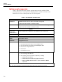
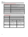
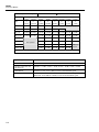
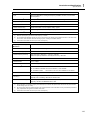
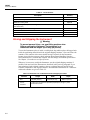
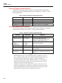
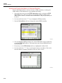
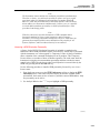
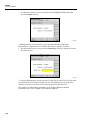
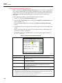
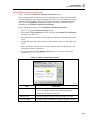
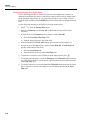
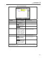
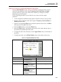
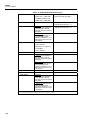
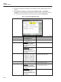
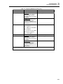
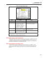
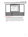
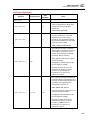
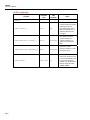
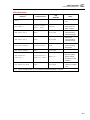
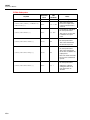
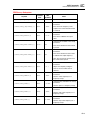
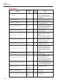
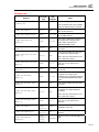
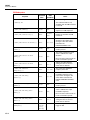
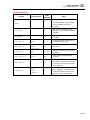
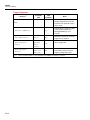
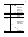
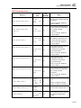
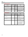
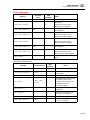
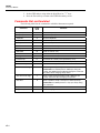
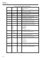
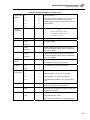
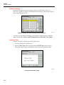
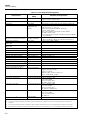
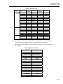
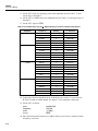
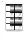
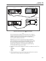
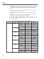
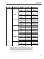
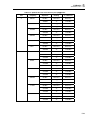
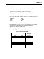
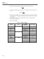
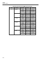
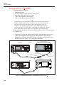
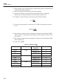
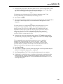
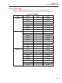
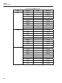
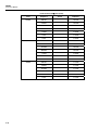
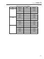
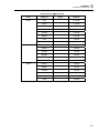
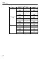
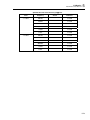
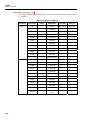
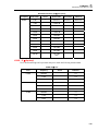
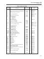
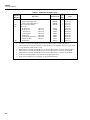
9640A
Instruction Manual
Table 7-1. Descriptions of the Rows in a Test Failure Display
Row
1
Identifier
Description
Failure Number
Incremental test number (starting at 1) assigned to each
failed measurement
Test Point Name
An encoded string containing the following:
• Major Assembly Identification [1]
S = A1 Synthesizer PCA
A = A2 RF Output PCA
H = A9 Leveling Head
•
Schematic Sheet Identification (2 digits)
•
Schematic Test Sequence Number (3 digits)
2
Test Point Description
Brief description of the test point such as “+15V Supply
via U909.3”
3
Nominal
Expected measurement value
4
Lower and Upper Limit
Prescribed lower and upper limit of the measured value
5
Measured Value and
Calculated Error
Actual measured value
Flags
Status of the detectors relevant to the test point. Indicate
OK unless there is a failure.
6
Error calculated from the measured value, the nominal
value, and either the upper or lower limit to indicate the
relative extent of the failure
e.g. PLL1 UNLOCKED
indicating that phase locked loop number 1 is unlocked
[1] S04.003 would be the third test on sheet four of the A1 Synthesizer PCA.
At the schematic level, the sheet number generally refers to the source of the signal being measured or feature being
tested. There are cases that are more complex such as signals leaving the A1 Synthesizer PCA measured at their
destination on the A2 RF Output PCA.
For A1 Synthesizer PCA test points, U909.3 refers to input number 3 of the A1 Synthesizer PCA self-test multiplexer
(designator U909), which is routing the signal to the ADC. For A2 RF Output PCA tests, the multiplexer designator
refers to the RF Output PCA schematic.
Interpreting the Results
The failure information on the display can assist with isolating a problem to a given PCA.
For example, in a case where a single failure occurs, the code letter in the test point name
(S, A or H) will indicate which assembly is most likely to be the source of the problem.
(See Test Point Name encoding in Table 7-1.) However, in cases where multiple
assemblies show failures, isolating the problem is less straightforward. In these cases it
may be helpful to refer to the Chapter 6, Theory of Operation to help isolate the faulty
assembly. For example, one failure on the A1 Synthesizer PCA and several failures on
the A2 RF Output PCA could indicate that a satisfactory signal is not leaving the A1
Synthesizer PCA. As a result, tests on the A2 RF Output PCA will naturally fail. In this
case, the A1 Synthesizer PCA test point description in the box would help isolate the
source of the problem.
A1 Synthesizer PCA test failures relating to a single power supply are likely to be caused
by the A1 Synthesizer PCA itself, whereas failure of the majority of supplies may
indicate a fault with the A4 Power Supply PCA.
Failures of the A9 Leveling Head may be caused by faults on the A2 RF Output PCA. To
determine if a Leveling Head is at fault, plug it into a known good Base and test it again.
7-22