1
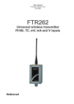
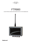
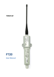
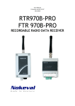
User Manual
Firmare version V3.2
19.8.2010
RTR970B
FTR 970B
RADIO DATA RECEIVER
DESCRIPTION
RTR970B and FTR970B have only one difference, the case. The benefits in upgraded B version:
Antenna is moved to the middle in both models and an USB- bus has been added to the FTR
model. B version of FTR is also about half the size of the original.
The device is a radio data receiver for Nokeval MTR series wireless transmitters. It receives and
buffers the data packets which have been sent by MTR transmitters. It automatically recognizes
the types of the transmitters, so different kinds of transmitters can be used simultaneously.
Transmitters can also have different transmission intervals. The device uses license free 433.92
MHz frequency band (ISM) so it can be freely used, for example, almost in whole Europe.
RTR970 is 35 mm DIN-rail mountable but desktop use is also possible. FTR970 is wall mountable.
The receiver is connected to a computer using RS-485, USB or RS-232 bus and it requires
PromoLog application that reads the information from the device.
Nokeval SCL protocol is used for data transmission between the receiver and the computer.
Multiple receivers can be connected in parallel to an RS-485 bus to increase the covered area. The
receiver has three indicator LEDs and it requires 8…30 VDC or USB.
covered area
2
CONTENTS
DESCRIPTION ............................................................................................................................... 2
CONTENTS ...................................................................................................................................... 3
INSTALLING ................................................................................................................................... 4
Where to install ........................................................................................................................... 4
Connections .................................................................................................................................. 4
SETTINGS ...................................................................................................................................... 9
Connection settings..................................................................................................................... 9
Menutree..................................................................................................................................... 9
SCL-PROTOCOL.......................................................................................................................... 10
SPECIFICATIONS ........................................................................................................................ 11
3
INSTALLING
WHERE TO INSTALL
The RTR model is 35 mm DIN-rail mountable and FTR is wall mountable. Desktop use is also an
option. The best place for a receiver is a big grounded horizontal metal level surrounded by as few
as possible vertical metal surfaces. Antenna is to be installed perpendicular to the metal level with
a corner piece or extension cord. The best range for the transmitter is achieved when there is a
direct view from receiver to the transmitter. The walls and objects between the transmitters will
dampen the signal and thereby shorten the range. On the other hand, metal surfaces cause
reflections which might lengthen the range.
CONNECTIONS
USB-, RS-485-, or RS-232-bus can be used to connect the device via
serial communications. Each of these connections will be covered
in their own chapter below. By default, the device is jumpered to
use the USB-bus. If RS-485 or RS-232 -bus is to be used, the serial
bus needs to be jumpered differently. Open the case by pressing in
the fasteners on both sides of the RTR970 case. The case of FTR970
is opened by removing the screws
ANTENNA CONNECTION
Antenna is attached to the BNC-connector by connecting the two locking pins, after which the
ferrule at the foot of the antenna is to be turned 90 degrees clockwise. Antenna can be removed
by turning the ferrule counterclockwise after which the antenna can be pulled off.
USB
To use USB-bus, jumper J11 has to be set as the picture below. Jumper J7 has nothing to do with
using the USB -bus. The device is jumpered like this as default.
The device gains the supply voltage through the USB, but to ensure that the device will operate
while the computer is turned off, connect the supply voltage 8...30 VDC either by 1.3 mm DC jack
(center connector positive) or by detachable screw post connector terminals 1 (+) and 2 (-). Both
supply voltage connectors are internally connected. The receiver is protected against wrong
polarity of the supply voltage.
4
RS-485
To use RS-485-bus, jumper J11 has to be set as the picture below.
The supply voltage 8...30 VDC is connected using 1.3 mm DC jack (center connector positive) or by
using detachable screw post connector terminals 1 (+) and 2 (-). Both supply voltage connectors
are internally connected. The receiver is protected against wrong polarity of the supply voltage.
The supply voltage's negative terminal is also used as ground for RS-485 and RS-232.
If necessary RS-485 interface can easily be added to a computer by using Nokeval DCS770 or
DC771B USB - RS-485 converter or RCS770 USB/RS-232-RS-485 converter. RS-485 bus is connected
to terminals 3 (D1) and 4 (D0).
If the master device in RS-485 bus has the common terminal, the ”two-wire” jumper must be set
to ”no” position. If the master device doesn't have the common terminal, the jumper must be set
to ”yes” position.
If the device is the last device on the bus, it is recommended to set the ”term” jumper to ”on”
position. When this jumper is set AC-termination is used which means that 1 nF capacitor and 110
ohm resistor are connected in series between the bus wires.
Length of RS-485 bus can be 1km and it can be connected to 32 devices, more can be connected
via repeating transmitters.
RS-232
To use RS-485-bus, jumper J11 has to be set as the picture below. Jumper J7 has nothing to do
with using the RS-232-bus.
The supply voltage 8...30 VDC is connected using 1.3 mm DC jack (center connector positive) or by
using detachable screw post connector terminals 1 (+) and 2 (-). Both supply voltage connectors
are internally connected. The receiver is protected against wrong polarity of the supply voltage.
The supply voltage's negative terminal is also used as ground for RS-485 and RS-232.
RS-232-bus is not recommended since it is easily disturbed and the maximum length of the cord is
only 15 meters in good circumstances. Long distances should be covered with RS-485-bus.
5
USB DRIVERS
The USB interface chip needs two drivers: one for USB bus and the other to create a virtual serial
port.
The drivers can be obtained from a Nokeval Software CD or downloaded from the homepage of
Nokeval at www.nokeval.com. The installation below assumes using CD, but using downloaded
drivers is quite similar.
Insert the Nokeval Software CD and plug in the device. Windows should detect it and start
installing automatically:
6
7
When USB bus driver ftdibus.inf is installed, Windows wants to install the virtual serial port driver,
which makes the device look like an ordinary COM port.
Install in the same way as the bus driver.
Finally it is necessary to find out, which COM port represents the device. Open Control Panel,
System, Hardware, Device Manager. In the device tree, expand Ports, and there should be USB
Serial Port (COM3), for example.
8
SETTINGS
CONNECTION SETTINGS
Use Mekuwin program to configure the device. You can download Mekuwin from Nokevals web
site for free.
Default communication settings for configuration:
• speed
9600 baudia
• protocol SCL
• address
0
MENUTREE
Menu of the device:
SERIAL-SUBMENU (SER)
Serial communication settings. Note that the changes here do not affect until the device is
rebooted.
Address:
SCL address selection. Allowed addresses are 0...123.
Baud:
Baud rate selection. Options are 300, 600, 1200, 2400, 4800, 9600 and 19200.
RECEIVE-SUBMENU (RCV)
CRCChk
If selected, CRC checksum of received data packets is checked and corrupted packets are rejected.
The setting is on by default and there is no reason to disable the setting.
CH1ID...CH4ID
Four MTR series transmitters (except MTR260 and FT10) can be defined to act as certain channel.
For example, when the device receives ”MEA CH 1?” command it sends latest received data from
the transmitter that has been assigned to channel one. To assign a device to channel one, set the
transmitter's ID to CH1ID value. Other channels can be assigned in the same way.
9
SCL-PROTOCOL
A more detailed description of the Nokeval SCL protocol can be downloaded from Nokeval wwwpages. Some additional commands have been added to SCL protocol for MTR and RTR series
devices that are not covered by the general SCL manual. These commands are explained in the list
below.
Device supports the following SCL commands:
TYPE ?
Returns the model name and software version.
SN ?
Returns the device's serial number, for example ”A123456”
MEA CH X ?
Returns the last received value from the device that is defined as ”channel x”.
DBG 1 ?
Returns the oldest unread data packet from the buffer.
DBR 1 XX ?
Returns a data packet from the ring buffer location xx.
DBX
Clears the ring buffer.
DBS 1 ?
Returns the size of the ring buffer.
10
SPECIFICATIONS
Radio receiver
Environment
Antenna
Connector:
50 Ω BNC female connector
Standard antenna: helical whip antenna (BNC
connector)
Radio
Operating temp.:
Protection class:
Max input power: +10 dBm
Frequency band: license free 433.92MHz sub band e
according to ERC/REC 70-03
Bandwidth:
180 kHz
Selective filter:
Yes, SAW type
Sensitivity:
-100 dBm
(3·10-3 error ratio)
Decoder
Buffer memory:
96 latest transmissions
RS:
RF:
Power:
Serial connections
Dimensions
RS-485
Connector:
RTR970B:
70 x 85 x 60 (WHD)
FTR970B:
80 x 130 x 60 (WHD)
Antenna:
100 mm, Ø 14 mm
Protocol:
Baud rates:
RS-232
Connector:
Protocol:
Baud rates:
USB
Connector:
Protocol:
Baud rates:
Detachable screw post connector
with 3.5 mm raster, combined with
power supply, terminal 3 D1,
terminal 4 D0.
Maximum cable length is 1000 m
Nokeval SCL
300/600/1200/2400/
4800/9600/19200
Detachable screw post connector
with 3.5 mm raster,
terminal 6 TxD, terminal 7 RxD.
Maximum cable length is 10 m
Nokeval SCL
300/600/1200/2400/
4800/9600/19200
USB type B, female
Nokeval SCL
300/600/1200/2400/
4800/9600/19200
Supply voltage
Connector 1
Connector 2
Connector 4
Voltage:
-30...+60 °C
RTR970B:
IP20
FTR970B:
IP65
LEDs
Serial bus indicator
Radio receiver indicator
Power indicator (behind RS and
RF LEDS)
Settings
Connection:
Protocol:
Software:
RS-232/485 or USB
Nokeval SCL-Meku 1
Mekuwin for Windows 98...XP
Regulations
EMC directive
EMC immunity
EMC emissions
R&TTE directive
EN 300 220 class 3
EN 300 489
EN 300 339
EN 61326
EN 61326, class B
1.3 mm DC-jack, center positive
detachable screw port connector
with 3.5 mm raster, terminal 1+,
terminal 2 -USB type B, female
8...30 VDC
11
Manufacturer
Nokeval Oy
Yrittäjäkatu 12
FIN-37100
Suomi
12
Tel +358 3 3424800
Fax +358 3 3422066
www.nokeval.com
Sales: [email protected]
Technical support: [email protected]