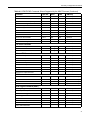
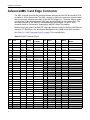
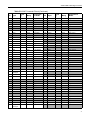
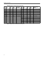
1
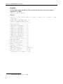
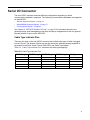
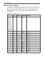
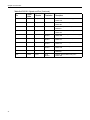
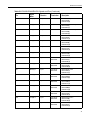
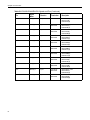
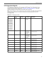
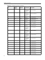
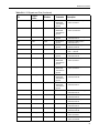
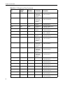
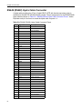
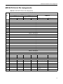
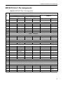
Serial I/O Connector
V.35 Supported Signals
This configuration supports the V.35 standard in a DTE format. The V.35 standard is also
supported through a hydra cabling option. Table 5-6, “V.35 Signals and Pins,” shows the
supported signals and their positions on the dual VHDCI connector.
Note: Some of the pins on the connector may not be included in the table. For each electrical
standard, the pins that are not included in the table for that standard MUST BE LEFT
UNCONNECTED.
Table 5-6: V.35 Signals and Pins
Pin
Signal
Name
Direction
B3, B6, B9, B12,
B15, B16, B19,
B20, B23, B26,
B29, B32, B37,
B40, B46, B49,
B50, B53, B54,
B60, B63, B66,
T3, T6, T12, T15,
T16, T19, T20,
T26, T29, T32,
T37, T40, T43,
T46, T49, T50,
T53, T54, T57,
T60, T63, T66
Termination
Description
Signal
Ground
B64
RXD(A)1
Input
100 Ohms
differential/
125 Ohms to
ground
V.35 Receive Data- port 1
.V.35 104, M-34 R
B65
RXD(B)1
Input
100 Ohms
differential/
125 Ohms to
ground
V.35 Receive Data+ port 1
.V.35 104, M-34 T
B55
DTR1
Output
NA
V.35 Data Terminal Ready port 1
.V.35 108, M-34 H
B58
TXD(A)1
Output
NA
V.35 Transmit Data- port 1
.V.35 103, M-34 P
B59
TXD(B)1
Output
NA
V.35 Transmit Data+ port 1
.V.35 103, M-34 S
B24
RTS1
Output
NA
V.35 Request To Send port 1
.V.35 105, M-34 C
B57
GND1
-
NA
V.35 port 1 Signal Ground
.V.35 102, M-34 B
B21
TXC(A)1
Output
NA
V.35 Transmit Clock- port 1
.V.35 113, M-34 U
B22
TXC(B)1
Output
NA
V.35 Transmit Clock+ port 1
.V.35 113, M-34 W
83