1
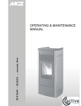
User Manual Version 2.0 C o p y r i g h t © E le c tr o n i c T h e a t r e C o n t r o l s , I n c . All Rights reserved. P r o d u c t in f o r m a t i on a n d s p e c i f i c a t i o n s s u bj e c t t o c h a n g e . P a r t N u m b e r : 7020M1200-2.0.4 R e v A Released: 10/2007 ET C ®, S m a r t P a c k ® , S m a r t S w i t c h ™ , a n d S m a r t L in k ™ a re e i t h e r r e g i s t e r e d t ra d e m a r k s o r t r a d e m a r k s o f E l e c t r o n i c T h e a t r e C o n tr o l s , In c . i n t h e U n i t e d S t a t es a n d o t h e r c o u n t r i e s . L o n W o r k s ® a n d L O N ® ar e t r a d e m a r k s o f t h e E c he l o n ® C o r po r a t i o n . A l l o th e r t r a d e m a r k s , b o t h m a r k e d a n d n o t marked, are the property of their respective owners. Table of Contents Introduction . . . . . . . . . . . . . . . . . . . . . . . . . . 1 Congratulations.... . . . . . . . . . . . . . . . . . . . . . . . . . . . . . . . . . . . .1 Using this Manual . . . . . . . . . . . . . . . . . . . . . . . . . . . . . . . . . . . .1 Overview . . . . . . . . . . . . . . . . . . . . . . . . . . . . 2 Standard Features . . . . . . . . . . . . . . . . . . . . . . . . . . . . . . . . . . . . . . .2 SmartPack Wall Mount . . . . . . . . . . . . . . . . . . . . . . . . . . . . . . . . . . . .3 SmartPack 19” Portable. . . . . . . . . . . . . . . . . . . . . . . . . . . . . . . .4 SmartPack Touring System . . . . . . . . . . . . . . . . . . . . . . . . . . . . .5 Chapter 1 Menu’s and Configuration . . . . . . . . . . . . . . . 7 User Interface . . . . . . . . . . . . . . . . . . . . . . . . . . . . . . . . . . . . . . . . . .7 Control Power Switch and LED Indicators. . . . . . . . . . . . . . . . . .7 Keypad. . . . . . . . . . . . . . . . . . . . . . . . . . . . . . . . . . . . . . . . . . . . .7 LCD Display. . . . . . . . . . . . . . . . . . . . . . . . . . . . . . . . . . . . . . . . .8 Initial Power Up Display. . . . . . . . . . . . . . . . . . . . . . . . . . . . . . . .8 Menu Lockout . . . . . . . . . . . . . . . . . . . . . . . . . . . . . . . . . . . . . . .8 Normal Menu Structure . . . . . . . . . . . . . . . . . . . . . . . . . . . . . . . . . . .9 Normal Menu . . . . . . . . . . . . . . . . . . . . . . . . . . . . . . . . . . . . . . . .9 Test Menu . . . . . . . . . . . . . . . . . . . . . . . . . . . . . . . . . . . . . . . . . .9 Advanced Menu Structure . . . . . . . . . . . . . . . . . . . . . . . . . . . . . . . .10 DMX. . . . . . . . . . . . . . . . . . . . . . . . . . . . . . . . . . . . . . . . . . . . . .10 Presets. . . . . . . . . . . . . . . . . . . . . . . . . . . . . . . . . . . . . . . . . . . .11 Sequencer . . . . . . . . . . . . . . . . . . . . . . . . . . . . . . . . . . . . . . . . .12 Dimmer Curves . . . . . . . . . . . . . . . . . . . . . . . . . . . . . . . . . . . . .13 Emergency. . . . . . . . . . . . . . . . . . . . . . . . . . . . . . . . . . . . . . . . .14 Stations . . . . . . . . . . . . . . . . . . . . . . . . . . . . . . . . . . . . . . . . . . .14 General Settings . . . . . . . . . . . . . . . . . . . . . . . . . . . . . . . . . . . .15 Diagnostics . . . . . . . . . . . . . . . . . . . . . . . . . . . . . . . . . . . . . . . .16 Chapter 2 SmartLink™ Enabled . . . . . . . . . . . . . . . . . 17 Features. . . . . . . . . . . . . . . . . . . . . . . . . . . . . . . . . . . . . . . . . . .17 Definitions . . . . . . . . . . . . . . . . . . . . . . . . . . . . . . . . . . . . . . . . .18 Pack Synchronization . . . . . . . . . . . . . . . . . . . . . . . . . . . . . . . . . . . .19 Preset and Sequence Synchronization . . . . . . . . . . . . . . . . . . .19 Wall Stations . . . . . . . . . . . . . . . . . . . . . . . . . . . . . . . . . . . . . . . . . .20 Station Options . . . . . . . . . . . . . . . . . . . . . . . . . . . . . . . . . . . . .21 Record a Preset from a Wall Station . . . . . . . . . . . . . . . . . . . . . . . .23 Table of Contents i Chapter 3 Service and Maintenance . . . . . . . . . . . . . . 25 Service . . . . . . . . . . . . . . . . . . . . . . . . . . . . . . . . . . . . . . . . . . . . . .25 Contacting ETC about Equipment Problems . . . . . . . . . . . . . . .25 Maintenance. . . . . . . . . . . . . . . . . . . . . . . . . . . . . . . . . . . . . . . . . . .26 Vacuum the Vents . . . . . . . . . . . . . . . . . . . . . . . . . . . . . . . . . . .26 Vacuum the Interior . . . . . . . . . . . . . . . . . . . . . . . . . . . . . . . . . .26 Replacement Parts . . . . . . . . . . . . . . . . . . . . . . . . . . . . . . . . . .26 Appendix A LinkPower supply Kit. . . . . . . . . . . . . . . . . . 27 Installation Procedure . . . . . . . . . . . . . . . . . . . . . . . . . . . . . . . .27 Appendix B ii Menu Flow Chart. . . . . . . . . . . . . . . . . . . . . 28 SmartPack User Manual Introduction Congratulations... on your purchase of the ETC SmartPack™ dimmer pack. SmartPack continues ETC’s tradition of providing the highest quality product for the entertainment and architectural lighting market. If you have questions regarding the operation or installation of your SmartPack system, please contact ETC Technical Services at the office nearest you. Using this Manual This manual contains information on the basic features and configuration for the SmartPack dimming pack with SmartLink™ enabled, wall station integration and maintenance procedures. The following symbols are used throughout this manual to alert you to danger or important information. Note: Notes are helpful hints and information that is supplemental to the main text. CAUTION: A Caution statement indicates situations where there may be undefined or unwanted consequences of an action, potential for data loss or an equipment problem. WARNING: A Warning statement indicates situations where damage may occur, people may be harmed, or there are serious or dangerous consequences of an action. WARNING: RISK OF ELECTRIC SHOCK! This warning statement indicates situations where there is a risk of electric shock. Please email comments about this manual to: [email protected] Introduction 1 Overview SmartPack’s are designed to provide SCR-based, professional quality dimming packaged for portable, touring and permanent installations. ETC offers three versions of the SmartPack including the SmartPack 19” Portable Pack, SmartPack Touring Systems, and the SmartPack Wall Mount unit. Standard Features 2 • DMX512 native • SmartLink™-enabled for pack to pack synchronization. • True SCR reliability based on Sensor™ technology. • Thirty-two programmable presets and a built-in sequencer for stand-alone operation. • Ultra-quiet variable speed cooling fan. • Multi-language user interface including English, Spanish, German, and French. • User selectable dimming curves. • Fully rated magnetic circuit breakers. • Auto restart function for day to day operation. • Stable dimming even with the poor power quality. • Emergency contact input with load-shedding capability. SmartPack User Manual SmartPack Wall Mount The SmartPack Wall Mount unit with SmartLink™ enabled provides total versatility and convenience for venues requiring low profile permanently installed dimming. The SmartPack Wall Mount unit may be installed with or without other system components, ensuring the lowest possible cost ownership. In addition, a rack mount kit is available for easy equipment rack installations. Product Variants SL620W SL1210W SL615W-CE SL1210W-CE Model Part Number Channel Count Breaker Type SL620W 7021A1100 6 20A SL620W-LPS 7021A1100-LPS 6 20A SL1210W 7021A1101 12 10A SL1210W-LPS 7021A1101-LPS 12 10A Model Part Number Channel Breaker Count Type SL1210W-CE 7021A1103 12 10A SL1210W-CE-LPS 7021A1103-LPS 12 10A SL1210W-CE-ND 7021A1105 12 10A ND SL1210W-CE-ND-LPS 7021A1105-LPS 12 10A ND SL615W-CE 7021A1106 6 15A SL615W-CE-LPS 7021A1106-LPS 6 15A SL615W-CE-ND 7021A1107 6 15A ND SL615W-CE-ND-LPS 7021A1107-LPS 6 15A ND Overview Voltage/Supply Description 85-140V 47-63Hz 3Ø or 1Ø 85-140V 47-63Hz 3Ø or 1Ø 85-140V 47-63Hz 3Ø or 1Ø 85-140V 47-63Hz 3Ø or 1Ø Wall Mount with 6-20A dimmers Wall Mount with 6-20A dimmers and LinkPower Supply Wall Mount with 12-10A dimmers Wall Mount with 12-10A dimmers and LinkPower Supply Voltage/Supply Description 230V/ 47-63Hz 3Ø or 1Ø 230V/ 47-63Hz 3Ø or 1Ø 230V/ 47-63Hz 3Ø or 1Ø 230V/ 47-63Hz 3Ø or 1Ø Wall Mount with 12-10A dimmers 230V/ 47-63Hz 3Ø or 1Ø 230V/ 47-63Hz 3Ø or 1Ø 230V/ 47-63Hz 3Ø or 1Ø 230V/ 47-63Hz 3Ø or 1Ø Wall Mount with 12-10A dimmers and LinkPower supply Wall Mount with 12-10A dimmers with 2-pole breakers Wall Mount with 12-10A dimmers with 2-pole breakers and LinkPower supply Wall Mount with 6-15A dimmers Wall Mount with 6-15A dimmers and LinkPower supply Wall Mount with 6-15A dimmers and 2-pole breakers Wall Mount with 6-15A dimmers, 2-pole breakers and LinkPower supply 3 SmartPack 19” Portable The SmartPack portable dimmer packs are designed in a rugged 19-inch 2-space rack mount package. Ships standard with SmartLink™ enabled for total versatility. • UL listed SmartPack portable dimming packs are available with either six 20A dimmers or twelve 10A dimmers. • CE marked SmartPack portable dimming packs are available with either six 15A dimmers or twelve 10A dimmers. In addition the SmartPack 19” portable pack is available with a wide variety of output panel options to fit industry needs. UL Rear Panel Options CE Rear Panel Options 6 Channel 12 Channel 6 Channel 12 Channel Edison Edison Schuko NF French Swiss PowerCon® Harting Multipin Socapex Multipin UK 15A Roundpin Terminal Output Stage Pin Stage Pin ® ® Twist-Lock Japanese Twist-Lock PowerCon Dual 6 circuit Multipin PowerCon® Single 6 circuit Multipin Terminal Strip Terminal Strip Power Con® Wireland GST18 Harting Socapex Model Part Number Channel Count Breaker Type SL620 7020A1000 6 20A SL1210 7020A1001 12 10A 4 Model Part Number Channel Count Breaker Type SL615 7020A1002-xx 6 15A SL615-ND 7020A1004-xx 6 15A ND SL1210 7020A1003-xx 12 10A SL1210-ND 7020A1005-xx 12 10A ND Voltage/Supply Description 120/240VAC 1Phase 120/208VAC 3Phase 120/240VAC 1Phase 120/208VAC 3Phase Portable unit 6 - 20A dimmers with output panel and SmartLink enabled Portable unit 12 - 10A dimmers with output panel and SmartLink enabled Voltage/Supply Description 230-240V AC 47-63Hz 230-240V AC 47-63Hz 230-240V AC 47-63Hz 230-240V AC 47-63Hz Portable unit 6-15A dimmers with output panel and SmartLink enabled Portable unit 6-15A dimmers with 2-pole breakers, output panel and SmartLink enabled Portable unit 12-10A dimmers with output panel and SmartLink enabled Portable unit 6-15A dimmers with 2-pole breakers, output panel and SmartLink enabled SmartPack User Manual SmartPack Touring System Standard UL 2XSL1210 shown The SmartPack touring system offers small compact design built to travel. Standard UL touring rack provides room for 2 or 4 SmartPack dimmer packs with the similar output panel options as available in the SmartPack 19” portable pack and SmartLink enabled. The UL SmartPack touring system includes built-in mains distribution with options for a main circuit breaker or a Cam-lok® Feed-Thru panel. Standard CE touring racks are available in a road case any 2 SmartPack’s of your choice with similar output panel options as available with the CE SmartPack 19” portable pack. The CE SmartPack touring system is SmartLink™ enabled and includes circuit breaker power distribution per pack with options for a mains breaker and RCD protection, and a convenience outlet for accessories. All the standard features of the SmartPack Portable unit in a industrial grade road case. Contact ETC for configuration details. Overview 5 6 SmartPack User Manual Chapter 1 Menu’s and Configuration User Interface The SmartPack family user interface and menu structure provide users an intuitive easy setup with multiple language options built-in. Control Power Switch and LED Indicators Power LED Standby / Control Power Switch DMX LED DMX Use the Standby/Control power switch to start up and shut down operation of the SmartPack. When the breaker is in the “On” position, the blue Power LED is illuminated indicating the power is on. WARNING: When the Standby/Control power switch is in the “Off” position, the unit is still connected to the power supply. When working on exposed load circuit wiring the load cables must be unplugged or the unit disconnected from the power supply. The green DMX LED indicates a DMX signal. When no DMX signal is present, the green LED will flash. When a stable DMX control signal is present the green LED will illuminate fully. Keypad DMX Symbol Description << Return to the home menu < Move back one menu item Accept a menu choice or store a value << 1 < + - Menu’s and Configuration + Increase a value or scroll through the menu - Decrease a value or scroll through the menu Activate the Test menu 7 LCD Display The display is a high contrast 20-character by 2-line backlit LCD. The control symbol, indicated in the top right corner of the LCD, indicates the current control source. d = DMX DMX: 001 > 012 P = Preset d Level: S = Sequence Control Symbol Note: T = Test If you discover a blinking “C” in the top left corner of the LCD, one or more of the power cubes has exceeded the maximum operating temperature of 90° Celcius. When you have corrected the temperature problem, the error should clear. If the error still persists, contact ETC Technical Services for assistance. When configuring the SmartPack: • Characters or [TEXT] in brackets indicate an item can be selected • Characters or >Text< in angle brackets indicate an item is selected Adjusting the Contrast of the LCD Display Press and hold << and use the + and - buttons to adjust the contrast of the LCD display. Initial Power Up Display The first time you apply power to the SmartPack you will be asked to choose a language for the operating system. The language options will cycle through the following four options at three second intervals. Set Language - English Choisir la langue - Français Sprache auswählen - Deutsch Press to set the displayed language option. Seleccionar idioma - Español Menu Lockout The menu lockout function restricts users from performing any changes to the current operation of the SmartPack from the facepanel. When lockout is enabled, the emergency contact input, SmartLink station control and incoming DMX levels still affect change in the output level of the Smartpack dimmers. Set levels from the test menu prior to engaging lockout will be held until lockout has been disengaged. To engage menu lockout: Press and hold + and - buttons for a period of 5 seconds. • When lockout is on, all local controls are disabled. If a user interface button press is received, the unit will CONTROLS LOCKED display a lockout dialog for three seconds then return ENTER UNLOCK CODE to the main status display. To disengage menu lockout: Press and hold + and - buttons for a period of 5 seconds. The display returns to the main status display and all controls function normally. 8 SmartPack User Manual Normal Menu Structure Normal Menu The normal menu is used to view system status and to set the DMX start address for SmartPack. The start address range is determined by the size of your SmartPack. DMX Start Address range: 6 channel: 001-507 12 channel: 001-501 Set the DMX start address: Step 1: Scroll to DMX, press . Step 2: Scroll to DMX Start Address, press Step 3: Use + or - to scroll the start address range. Step 4: Press . to set the start address. Test Menu The test menu is a tool for testing dimmers and loads. In the absence of a DMX control source, the test menu may also be used to set dimmer levels for snapshot into a preset. Enter the Test menu From any menu, press the test button Test Dimmer: [ All ] . T Level: 100% Set dimmer levels in the Test Menu Step 1: Use < or to select one or [ALL] dimmers. Step 2: Use + or - to set a level, press Step 3: Press . The menu will progress to the next channel. , “Exit Test Mode: [Test: all off]” displays. To exit the Test menu and retain all Test Levels: Scroll to [Keep test on] and press . Exit Test menu, clearing all Test Levels and return to the previous menu: Scroll to [Test: all off] and press . Press << to return to the main menu and clear all Test Level. 1 Menu’s and Configuration 9 Advanced Menu Structure Enter the Advanced menu from the Normal Menu: The Advanced menu provides all access to the menu and configuration settings for the SmartPack. Step 1: Scroll to General Settings, press Step 2: Scroll to Menu Mode, press Step 3: Scroll to Advanced Menu, press and hold for 5 seconds. The display will return to the main menu when the Advanced Menu has been accessed. • If the mode. . is released prematurely the menu will remain in Normal Menu DMX DMX Start Address The start address range is determined by the size of your SmartPack. When a DMX Start Address is selected as the active DMX Mode, the DMX range will be displayed on the LCD. DMX: 001 > 012 Level: DMX Start Address range • A six channel unit allows a start address range of 001-507. • A twelve channel unit allows a start address range of 001-501. Step 1: Scroll to DMX, press . Step 2: Scroll to DMX Start Address, press Step 3: Use + or - to increment or decrement the Start Address range. Press address and return to the previous menu. Step 4: Press < to return to the previous menu or press << to return to the main menu. The specified DMX range will display on the LCD. . to set the DMX Patch DMX Patch allows the user to patch different DMX numbers to selected dimmers. This menu is to be used when setting the DMX Start Address is not sufficient. When DMX Patch is selected as the active DMX Mode, “DMX Patch” will be displayed on the LCD. DMX Patch Level: 10 Step 1: Scroll to DMX, press . Step 2: Scroll to DMX Patch, press Step 3: Use + or - to increase dimmer channel. Dimmers will be numbered 1-6 or 1-12 depending on the SmartPack channel count. Initially the DMX address will patch consecutively with the dimmer channel. If the DMX address should differ from the channel number, press . Step 4: Dim ## > DMX [###] will display. Press + or - to change the DMX address. . SmartPack User Manual Step 5: Press to return to the dimmer channel selection. Continue with steps 3 and 4 until all dimmers are patched to the required DMX Address. Step 6: Press < to return to the previous menu or press << to return to the main menu. “DMX Patch” will display on the LCD. DMX Loss Behavior DMX Loss Behavior may be set to either Hold Last Look, Fade to Preset, or Wait and Fade Out. • Hold Last Look - holds any active dimmers at whatever levels they were receiving when the data was lost. The dimmers will remain on until data is restored or the SmartPack is reset. • Wait and Fade - holds any active dimmers at whatever levels they were receiving when the data was lost for a user-defined amount of time and then fade those dimmers to zero in a user-defined fade time. The maximum wait and fade time is 59min:59sec. • Fade to Preset - plays a user-defined preset when data is lost. Step 1: Scroll to DMX, press . Step 2: Scroll to DMX Loss Behavior, press Step 3: Use + or - to select the desired Loss Behavior, press Step 4: Use + or - to set the values as required, press Step 5: Press < to return to the previous menu or press << to return to the main menu. . . . DMX Mode DMX Mode is provided as a shortcut for switching between DMX Start Address and DMX Patch. The LCD will either display the DMX address range or “DMX Patch”, depending on the mode selected. Presets SmartPack features up to 32 built-in presets which can be recalled without the need of any external control system. For SmartLink enabled systems with a LinkPower supply installed, up to four 5 or 10 button preset stations may be used for remote recall of the built in presets and sequence. See “Stations” on page 14. Note: In addition these 32 presets are available for use in the built-in sequencer. See “Sequencer” on page 12. For best results, presets should be recorded sequentially as they would be recalled in a sequence. When you record a preset, SmartPack will snapshot any level whether set in the test menu or by a DMX input. If both levels are present it will record all levels. When a new preset is recorded using the same preset number, SmartPack will record over the previous levels. Unless preset timing is configured otherwise, presets are activated in the default fade up and fade down time of 3 seconds. Record a Preset (snapshot) 1 Step 1: Set dimmer levels with an external DMX source and/or set test levels. Step 2: Scroll to Presets menu, press . Step 3: Scroll to Record Preset, press . Step 4: Press + or - to select the desired preset number then press briefly display. Menu’s and Configuration . Preset record will 11 Setup Preset Timing Step 1: Scroll to Presets menu, press . Step 2: Scroll to Setup Timing, press . Setup Timing, Preset / Step: [##] will display. Step 3: Press + or - to scroll the presets list. Press Step 4: Press + or - to increase or decrease the Fade Up minutes. Press selection will change to the seconds field. Step 5: Press + or - to increase or decrease the Fade Up seconds. Press [min]:03 will display. Step 6: Repeat steps 4 and 5 for Fade Down. Press . Hold Time [min]:00 will display. Step 7: Repeat steps 4 and 5 for Hold Time. Press when done. , Fade Up [min]:03 will display. . The . Fade Down Activate a Preset Step 1: Scroll to Presets menu, press . Step 2: Scroll to Activate Preset and press Step 3: Press + or - to scroll the list of presets. Press Step 4: “Preset ## Run Instant?” will display briefly. , Number [##] will display. to select a preset. a: To run the preset with its programmed Fade Up and Fade Down times, ignore the “Run Instant?” message. The display will return to the previous menu after a few seconds of display. b: Press to complete the preset in the default time of 3 seconds. The display will default to the previous menu. Deactivate a Preset If a Preset is active, the control symbol located in the top right corner of the LCD will display the preset number and the P symbol. To deactivate the preset: Step 1: Scroll to Presets menu, press . Step 2: Scroll to Deactivate Preset and press then returns to the previous menu. . “Preset Deactivated” will display briefly Sequencer The built in sequencer in SmartPack plays a series of recorded presets sequentially. The order of execution is based on the first preset and the length is determined by the number if steps configured for the sequence. Fade Up, Fade Down and Hold Times are determined in the preset menu and may be different for each preset. The sequence can be set to loop continuously or stop after only one occurrence. Setup a Sequence 12 Step 1: Scroll to Sequencer, press . Step 2: Scroll to Setup Sequence, press Step 3: Use + or - to select the number of steps to be included in the sequence (up to 32). The Sequencer will play the steps in series with preset one as step one always. Press , Loop: [NO] will display. Step 4: Scroll to select [Yes] to continuously loop the sequence or [No] to play the sequence only once and then stop. Press . . SmartPack User Manual Star t / Stop a Sequence Step 1: Scroll to Sequencer, press . • Start the sequence, scroll to Start Sequence and press . Sequence Started will briefly display and the control symbol on the LCD will display the “S”. Note: The sequence will start at preset 1 and run for a user configured number of steps. If the sequence is not configured to loop, the sequence will stop. If the sequence is configured to loop, the sequence will start at preset 1 and continue looping until the sequence is deactivated. • Stop the sequence, scroll to Stop Sequence and press . Sequence Stopped with briefly display and the control symbol on the LCD will no longer display the “S”. Dimmer Curves SmartPack is capable of dimming multiple load types including incandescent, low voltage and 2-wire fluorescent. SmartPack provides five user-selectable dimmer output curves to choose: • IES modified square law • Linear • Switched (50% threshold, non-regulated) • Fluorescent with adjustable cut-off • Adjustable pre-heat Set Dimmer Curve Step 1: Scroll to Dimmer Curves, press . Step 2: Use + or - to select the specific dimmer number (or ALL) to be modified. Press Step 3: Use + or - to scroll through the five options, press choice. . to select the output curve of a: If Fluorescent output curve is selected you must specify the Start Voltage. • Fluorescent circuits provide a dimmable output in the 5% to 100% control range. Trim the minimum RMS output voltage to match your specific ballast. • The default voltage is 47% of your mains voltage. Use + or - to increase or decrease the Start Voltage value. • Consult the ballast manufacturer’s documentation for the appropriate minimum start voltage. b: If Preheat output curve us selected you must specify the preheat level (allowable 0% - 20% range). 1 Menu’s and Configuration 13 Emergency SmartPack is provided with a emergency contact input. When an active emergency contact is received all non-emergency dimmers in the SmartPack are forced off while all userselected emergency dimmers energize to full. During an emergency the LCD will display a message advising the “Emergency Input Is Active” and the menu will lock-out all ability to access the system. After normal power is restored, the SmartPack will restore to the configured DMX Loss Behavior mode. See “DMX Loss Behavior” on page 11. Assign Dimmers as Emergency Loads Step 1: Scroll to Emergency, press . Step 2: Scroll to [Assign Dimmer], press Step 3: Use + or - to scroll the dimmer list. Press Step 4: Use + or - to scroll “In Emergency” [Yes] or [No], press Step 5: Press < to return to the previous menu or << to return to the main menu. . to select a dimmer. . Stations A SmartPack dimming pack, with SmartLink enabled and a LinkPower supply (S-LPS) installed, facilitates the communication of host messages (reference page 18 for host messages) between SmartPack dimmer packs and the use of up to four SmartLink wall stations. See “Wall Stations” on page 20. SmartPack SmartSwitch SmartPack SmartSwitch Belden 8471 LinkPower supply installed Presets, Sequence, Sequence timing SmartLink wall stations Note: A SmartLink network is limited to four SmartLink wall stations and up to four SmartPack or SmartSwitch products in a system. One SmartPack or SmartSwitch in the system must have a LinkPower supply installed for wall station power. Assign Station Master One SmartPack in a system with wall stations installed should be configured as the “Station Master”. The station master tracks and updates button LED states for connected wall stations when preset or sequence changes occur. In addition the station master sends host messages to other SmartLink enabled SmartPack dimmer packs in the system. Note: ETC recommends configuring the SmartPack with the LinkPower supply installed and wall stations connected as the “Station Master”. For systems without wall stations, there is no requirement to configure a station master. 14 SmartPack User Manual Default functionality for pack to pack synchronization is that the last SmartPack or SmartSwitch updated in the system acts as the station master and send its host messages to the other products in the system. Step 1: Scroll to [Stations] and press . Step 2: Scroll to [Station Master] and press . • If the SmartPack you are configuring is to be the Station Master, scroll to [Enable] and press . • If the SmartPack you are configuring is not the Station Master, scroll to [Disable] and press . Remot e Record Enable “Remote Record” within the station master for user ability to record presets from SmartLink wall stations. Disable “Remote Record” within the station master to lock-out the ability to record presets from SmartLink wall stations. Step 1: From the face panel of the station master, scroll to [Stations], press . Step 2: Scroll to [Remote Record], press Step 3: For the ability to record a preset from a SmartLink wall station scroll to [Enable] and press . . • After enabling “Remote Record”, the user has the option to set dimmer levels to a desired look (via the test menu or other DMX control device) and record that look to a specific preset via the wall station. See “Record a Preset from a Wall Station” on page 23. Step 4: If the ability to record a preset from a wall station is not desired scroll to [Disable] and press . • If disabled, preset recording must be accomplished from the face panel of the station master. See “Presets” on page 11. General Settings The General Settings menu is used to configure standard features of your SmartPack dimmer pack including: Set Language Multiple language options to choose from: • English • Francais • Deutsch • Espanol LCD BackLight User-selectable LCD backLight performance: 1 • Auto - LCD dims when not in use for period of time • On - always on • Off - always off Menu’s and Configuration 15 Menu Mode User-selectable Normal Menu or Advanced Menu: • Normal - limited menu options allowing users only to change the DMX Start Address from the DMX menu, view the Software Version and change menu mode from the General Settings menu. • • To enter Normal mode from the Advanced menu, scroll to [Normal] and press . The SmartPack will request confirmation that you want to exit the Advanced menu, scroll to [Yes] and press . Advanced - all menu access. • To enter Advanced mode from the Normal menu, scroll to [Advanced] and press and hold for 5 seconds. The menu will adjust back to the main menu automatically, without further prompt. Reset To Defaults Resets the following attributes to default status: • Dimmer Curves - set to >Mod SQR Law< • DMX Start Address - set to start address >1-6 or 1-12< • DMX Loss Behavior - resets to >Hold Last Look< Deep Clear System Resets the unit as if it were new, out of the box including the following attributes: • Resets same defaults as indicated in Reset to Defaults • Clears presets and preset timing values to default values • Resets Language and prompts the user for language selection Software Version Displays current software version Power Up Behavior Choose between Normal or Previous State: • Normal - the SmartPack powers up with both presets and the sequencer de-activated. • Previous State - powers up the SmartPack with the preset or the sequence active that was running during the previous session. This feature allows unattended operation through power blackouts. This state will not restore Test levels. Diagnostics The diagnostics menu provides feedback of line errors and temperature readings for each line. The initial display shows the temperature reading in °C, press the - button for °F readings. 16 SmartPack User Manual Chapter 2 SmartLink™ Enabled Features SmartLink is a communications network created for enhanced control of the 32 built-in presets and a sequencer as found in SmartLink enabled SmartPack and SmartSwitch products. The addition of the SmartLink network facilitates two additional control features, wall stations and pack to pack synchronization. Neither control feature is dependent upon the other for operation but instead rely independently on the SmartLink network and specific host messages. Note: The SmartPack Portable dimmer packs do not share the same I/O panel as the SmartPack Wall Mount. Utilize the RJ45 connectors located on the rear panel of the portable unit for SmartLink In and Thru. Reference the SmartPack Portable Setup Guide for output panel details. ™ SmartLink enabled I/O panel to chassis ground LinkPower supply (optional) v Data to CPU v SmartLink / Emergency v DMX IN DMX-Thru ESD Ground 2 • Synchronization - each SmartPack and SmartSwitch in the system must have the I/O board installed (i.e. SmartLink enabled) and connected on the SmartLink network. A SmartLink enabled SmartPack is identified by the logo on the front of the unit. Up to four SmartPack or SmartSwitch products may be utilized on the SmartLink network. • Wall Station - In addition to the I/O board, one SmartPack or SmartSwitch in the system must have a LinkPower supply (SL-LPS) installed. The LinkPower supply powers up to four SmartLink wall stations. ETC reccommends installing the LinkPower supply in the same SmartPack or SmartSwitch product that the station data run terminates and utilizing that product as the “station master”. SmartLink™ Enabled 17 Definitions 18 • Host Product - any SmartLink enabled SmartPack within a system that sends specific host messages to other SmartLink enabled products in the system for preset and sequence synchronization. Default functionality is that the last SmartPack updated in the system acts as the host product and sends its host messages to the other products in the system. If a preset or sequence is activated from another pack in the system, it will then act as the host product and send its host messages to the other products in the system. • Station Master - any SmartLink enabled SmartPack, with a LinkPower supply installed, that is configured via the menu to control wall stations, track and update LED status when preset or sequence changes occur, and receive host messages from the wall stations when a button is pressed and released. In addition the “station master” will act as the “host product” for preset and sequence synchronization. ETC reccommends configuring the product with the LinkPower supply installed and the station data runs terminated as the “station master”. • Host Messages - specific configuration settings and events sent from the host product to other SmartLink enabled products for lock step synchronization of preset and sequence playback. Host messages communicated include: • DMX Loss Behavior: Hold Last Look, Wait and Fade, or Fade to Preset. Wait and Fade Times or Fade to Preset Number, if applicable • Sequence: Start, Stop and Loop Yes or No • Preset: Fade Up Time, Fade Down Time and Hold Time • Language: Language selected • Station Master: Enable or Disable • Power Up Behavior: Normal or Previous State SmartPack User Manual Pack Synchronization It is possible to synchronize presets and sequence activation across up to four SmartPack or SmartSwitch products when they are connected on a SmartLink network. SmartLink connected products share various configuration parameters and events, known as host messages, as sent from the host product. Reference page 18 for host messages defined. SmartPack Portable SmartSwitch SmartPack SmartSwitch Belden 8471 Presets, Sequence, Sequence timing Preset and Sequence Synchronization Default functionality is that the last SmartPack or SmartSwitch updated in the system acts as the host product and sends its host messages to the other SmartLink enabled products in the system. Each product (SmartPack and SmartSwitch) will retain its own preset and sequence configuration as programmed but when a host product is selected each SmartLink enabled product will activate and play its sequence with the number of steps and timing (fade up, fade down, hold time) as sent by the host product. Preset Synchronization Selecting a preset on any pack affects the same numbered preset to run on all inter connected SmartLink enabled products simultaneously. If “Preset 1” is activated from the facepanel of a SmartPack: That SmartPack will act as the host product and send its host messages to the other SmartLink enabled products in the system to activate “Preset 1”. The preset will activate with the same fade up time, hold time, and fade down time as sent from the host product. Sequence Synchronization Activating a sequence on any pack causes all connected SmartLink enabled SmartPack and SmartSwitch products to run the same sequence in lock-step synchronization using the host product fade up, hold, and fade down times. In addition, sequence loop “yes” or “no” will be sent from the host product to all inter-connected SmartLink enabled products to ensure lock step synchronization. If the sequencer is activated from the facepanel of a SmartPack: That SmartPack will act as the host product and send its host messages to the other SmartLink enabled products in the system. Each SmartLink enabled product in the system will activate the sequence as sent from the host product with steps and timing synchronized. If one product in the system does not have specific step recorded and the host product sends the message to play that step, the receiving product will simply ignore that command and pick up with the next recorded event. 2 SmartLink™ Enabled 19 Wall Stations Two wall station types are available for use on the SmartLink network, a 5 button and a 10-button. Wall stations provide remote access to the 32 built-in presets and sequencer in the SmartPack. Note: Wall station use with the SmartPack Portable dimmer pack requires additional hardware that is separate from the pack itself. Contact ETC for assistance. A LinkPower supply must be installed into one SmartPack Wall Mount and is required to operate up to four wall stations per system. The LinkPower supply is available factory installed or as a kit (S-LPS) for field installation. Reference LinkPower supply Kit, page 27 for installation instructions. SmartPack SmartSwitch SmartPack SmartSwitch Presets, Sequence, Sequence timing Belden 8471 LinkPower supply installed SmartLink wall stations Note: 20 A SmartLink network is limited to four SmartLink wall stations and up to four SmartPack or SmartSwitch products in a system. A SmartLink data run is limited to 1500 feet and is FTT-10A topology-free and polarity-independent. SmartPack User Manual Station Options Control station electronics mount directly into a flush mount, single gang, industry standard back box. Station faceplates are constructed of ABS plastic and use no visible means of attachment. All stations are available in white, ivory, gray or black faceplates and buttons. Note: Reference the SmartLink Wall Station Installation Setup Guide for complete station installation details. 5 Button 10 Button Preset 1 Preset 1 Preset 6 Preset 2 Preset 2 Preset 7 Preset 3 Preset 3 Preset 8 Preset 4 Preset 4 Preset 9 Sequence Preset 5 Preset 10 A sampling of the standard legends available include: 5 - Button Station 10 - Button Station Presets Only Presets and Sequence Presets Only Presets and Sequence Preset 1-5 Preset 1-4 and Sequence Preset 1-10 Preset 1-9 and Sequence Preset 6-10 Preset 5-8 and Sequence Preset 11-20 Preset 10-18 and Sequence Preset 11-15 Preset 9-12 and Sequence Preset 21-30 Preset 19-27 and Sequence Preset16-20 Preset 13-16 and Sequence Preset 21-25 Preset 17-20 and Sequence Preset 26-30 Preset 21-24 and Sequence Preset 25-28 and Sequence Preset 29-32 and Sequence Custom options available, contact ETC quotations department for assistance. 2 SmartLink™ Enabled 21 Station Personality Settings The control electronics (back side) include a set of eight dip switches. Each setting activates standard functionality or personalities from within the station including the starting preset number and sequence looping. back side electronics UP 1 2 3 OF F 4 5 6 7 8 set of 8 dip switches DHS-8 1 2 3 4 5 6 7 8 front side electronics OFF The table below indicates dip switch settings for both the 5 button and the 10 button preset stations. Determine the functionality required and set the dip switches for station personality. Switch Number Station # Note: 22 2 3 4 5 Button Station 5 Switch 1 On = presets & sequence Switch 1 Off = presets only 10 Button Station Switch 1 On = presets & sequence Switch 1 Off = presets only 1 Off Off Off Off 1-4 1-5 1-9 1-10 2 On Off Off Off 5-8 6-10 10-18 11-20 3 Off On Off Off 9-12 11-15 19-27 21-30 4 On On Off Off 13-16 16-20 28-36 5 Off Off On Off 17-20 21-25 6 On Off On Off 21-24 26-30 7 Off On On Off 25-28 31-35 8 On On On Off 29-32 Switches 6-8 are reserved for future development and should remain in the “Off” position. SmartPack User Manual Record a Preset from a Wall Station It is possible to record a preset from a wall station if “Remote Record” has been enabled in the station master. See “Remote Record” on page 15. All SmartPack and SmartSwitch products on the SmartLink network will record the current output levels for the preset that is assigned to that button. Step 1: Set dimmer levels to a desired look via the test menu and/or other DMX control device. Step 2: Press and Hold the preset button for 5 seconds. Step 3: 2 SmartLink™ Enabled • After two seconds, the LED will start to blink at a 1/2 second interval. If the button is held for 5 seconds a record action will be begin. • If the button is released before the 5 seconds have elapsed, recording will be canceled and the normal preset will be activated. Release the preset button. The new recorded preset will activate and the LED will illuminate. 23 24 SmartPack User Manual Chapter 3 Service and Maintenance Service Contacting ETC about Equipment Problems If you are having difficulties, your most convenient resources are the references given in this manual. To search more widely try the ETC web site at www.etcconnect.com. If none of these resources is sufficient, contact ETC Technical Services directly at one of the offices listed below. Emergency service is available from all ETC offices outside of normal business hours. When calling for assistance, please have the following information handy: • Your location and job name • Model of SmartPack used • List of other installed products and components connected to the system you are troubleshooting. • DMX control source, if any. • Related system problems or equipment failures. Americas United Kingdom ETC International Electronic Theatre Controls, Ltd. Technical Services Department Technical Services Department 3031 Pleasant View Road 26 - 28 Victoria Industrial Estate Middleton, WI 53562 Victoria Road, 800-775-4382 (USA, toll-free) London W3 6UU, UK +1-608 831-4116 +44 (0)20 8896 1000 [email protected] [email protected] Asia Germany ETC Asia, Ltd. Electronic Theatre Controls, GmbH Technical Services Department Technical Services Department Room 1801/18F Ohmstrasse 3 Tower I Phase 1, Enterprise Square 93607, Holzkirchen, Germany 9 Sheung Yuet Road +49 (80 24) 47 00-0 Kowloon Bay, Kowloon, Hong Kong [email protected] +852 2799 1220 [email protected] 3 Service and Maintenance 25 Maintenance Vacuum the Vents Vacuum the dust from the airflow vents regularly. The interval between cleaning’s is dependant on the installation environment. Never allow the vents to become completely clogged with dust. Vacuum the Interior WARNING: High Voltage! Remove power from the SmartPack unit prior to removing the front cover. Step 1: Remove power from the SmartPack. Step 2: Remove the front cover of the SmartPack unit and detach the ground wire. Step 3: Vacuum dust from the interior of the unit. Use canned air to blow dust from the circuit boards to avoid possible damage from electrostatic discharge. Step 4: Reinstall front cover before applying power to the unit. Ensure that the ground wire is reattached to the front cover. Replacement Parts Two different fuses are used in three places on the SmartPack control board. Field replacements are available by ETC or may be purchased at your local electrical supply house. • Control board location “F1” and “F2” use fuse type 0.125A 250V F 5x20mm. ETC part number F113-F. • Control board location “F3” use fuse type 0.500A 250V F 5x20mm. ETC part number F112-F. All other field issues please contact ETC technical services for assistance. 26 SmartPack User Manual Appendix A LinkPower supply Kit One LinkPower supply is required to power up to four wall stations over the SmartLink™ network. A SmartLink system is limited to one LinkPower supply, up to four wall stations and up to four SmartLink enabled SmartPack or SmartSwitch products. Due to the similar design for the SmartPack Wall Mount and the SmartSwitch Relay Panel control terminations, the following instructions may be used for either product. Installation Procedure The LinkPower supply kit includes a LinkPower supply and four screws. Step 1: Remove power from the control electronics. a: For a SmartPack Wall Mount, turn the Standby breaker off. b: For a SmartSwitch relay panel, turn the circuit breaker off at the breaker panel. Step 2: Remove the two screws securing the I/O panel to the chassis. Step 3: Fold the I/O panel down to reveal the control terminations. Step 4 Step 5 LinkPower supply I/O board A Step 4: Angle the LinkPower supply board approximately 10° and insert the four pins as found on the LinkPower supply into the receptacle on the I/O board. Step 5: Align the LinkPower supply with the four screw mounts located on the I/O panel and secure with the four screws provided. Do not over tighten the screws. Step 6: Close the I/O panel and secure with the two screws. Step 7: Re-apply power to the control electronics. LinkPower supply Kit 27 28 ] ETC SmartPack [Presets ] ## ETC SmartPack [DMX DMX: 1 > 12 Level: Preset/Step ## Fade Up [mm]:[ss] Preset/Step ## Hold Time: [mm]:[ss] Preset Deactivated Record Preset Number: [##] Setup Timing Preset/Step: [##] Preset/Step ## Fade Down: [mm]:[ss] Presets ## [Deactivate Preset] Presets ## [Record Preset] Presets [Setup Timing] Preset ## Recorded Activate Preset Number: [##] DMX Response [dd] Packet Delay DMX Mode [Start Address] DMX Mode >DMX Patch< Presets ## [Activate Preset] DMX [DMX Response] DMX [DMX Mode] Wait and Fade Out Wait Time [##]:[##] DMX [Wait and Fade Out] DMX [Hold Last Look] DMX [DMX Loss Behavior] DMX Patch Dim ## > DMX [###] Fade to Preset Number [##] DMX Patch Dim [##] > DMX ### DMX [DMX Patch] DMX [Fade to Preset] Set Start Address DMX:[### -> ###] DMX [DMX Start Address] Appendix B Menu Flow Chart This appendix contains the SmartPack menu structure. SmartPack User Manual B Menu Flow Chart 29 Sequence Stopped Setup Sequence Number of steps:[##] Sequence “Active” Step ## Fade:mm:ss Sequencer [Stop Sequence] Sequencer [Setup Sequence] Sequencer [Sequencer Status] Station Master [Enable / Disable] Remote Record [Enable/Disable] Emergency [Assign Dimmer] Stations [Station Master] Stations [Remote Record] ETC SmartPack [Stations] Dimmer [##] In Emergency No Press and hold + and - for 5 seconds to disengage menu lockout. CONTROLS LOCKED, ENTER UNLOCK CODE Press and hold + and - for 5 seconds to engage menu lockout. When lockout is engaged and a button on the user interface is pressed, the unit will display a lockout dialog. Menu Lockout Dimmer ## In Emergency[Yes/No] or Set Start Voltage Fluorescent [##%] Dimmer num: [##] [Fluorescent] ETC SmartPack [Emergency] Set Pre Heat Level Pre-Heat [##%] Setup Sequence Loop: [yes or no] Dimmer num: [##] [Pre-Heat] Dimmer num: [##] >Mod SQR Law< Available curves: Modified Square Law Linear Pre-Heat Switched Fluorescent Sequence Inactive Sequence Started Sequencer [Start Sequence] ETC SmartPack [Dimmer Curves] ETC SmartPack [Sequencer] 30 SmartPack User Manual ETC SmartPack [Diagnostics] ETC SmartPack [General Settings] Menu Mode [Normal] [Advanced] Are you sure? [Yes / No] Are you sure? [Yes / No] Software Version [Ver:2.#.#] Power Up Behavior [Normal] [Previous State] General Settings [Menu Mode] General Settings [Reset to Defaults] General Settings [Deep Clear System] General Settings [Software Version] General Settings [Power Up Behavior] L1:OK L2:OK l3:OK ##HZ ##°F ##°F ##°F Exit Test Mode: [Keep Test On] Test: all off] DMX Address DMX:[###-###] Software Version v2.#.## General Settings [Normal Menu] [Advanced Menu] DMX [DMX Address] General Settings [Software Version] General Settings [Menu Mode] ETC SmartPack [General Settings] Normal Menu Test Dimmer: Ch: ## @ Level ###% Button Functions + Increment Level Decrement Level < Decrement Channel Increment Channel << Exit and Cancel Test Exit Test Mode Set Language [Espanol] Set Language [Deutsch] Test Menu Set Language [Francais] Set Language [English] Language choices cycle through the options at 3 second intervals.Select to set the displayed language. ETC SmartPack [DMX] DMX: 1>12 Level: [LCD Backlight [Auto] [ON] [OFF] General Settings [LCD BackLight] L1:OK L2:OK l3:OK ##HZ ##°C ##°C ##°C [English] [Francais] [Deutsch] [Espanol] General Settings [Set Language] First Time Power Up Display B Menu Flow Chart 31 Corporate Headquarters 3031 Pleasant View Road, P.O. Box 620979, Middleton, Wisconsin 53562-0979 USA Tel +608 831 4116 Fax +608 836 1736 London, UK Unit 26-28, Victoria Industrial Estate, Victoria Road, London W3 6UU, UK Tel +44 (0)20 8896 1000 Fax +44 (0)20 8896 2000 Rome, IT Via Ennio Quirino Visconti, 11, 00193 Rome, Italy Tel +39 (06) 32 111 683 Fax +39 (06) 32 656 990 Holzkirchen, DE Ohmstrasse 3, 83607 Holzkirchen, Germany Tel +49 (80 24) 47 00-0 Fax +49 (80 24) 47 00-3 00 Hong Kong Room 1801/F, Tower I Phase 1, Enterprise Square, 9 Sheung Yuet Road, Kowloon Bay, Kowloon, Hong Kong Tel +852 2799 1220 Fax +852 2799 9325 Service: (Americas) [email protected] (UK) [email protected] (DE) [email protected] (Asia) [email protected] Web: www.etcconnect.com Copyright © 2007 ETC. All Rights Reserved. Product information and specifications subject to change. 7020M1200-2.0.4 Rev A Released 10/2007