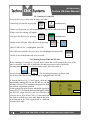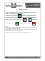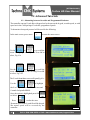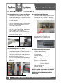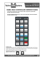
1
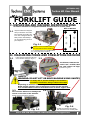
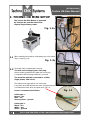
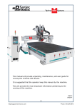
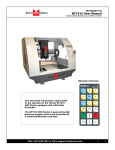
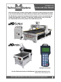
(HTT06021109)
Techno HD User Manual
This document will provide a quick guide to the set up and operating procedure
of the Techno HD Mini and Techno HD Series Router with a NCstudio Controller.
The HD Router is powered by high precision stepper motors and controlled by
a hand-held NCstudio controller. It operates independently of a PC and files
are transferred from a Cam system via a USB memory stick.
NCstudio Controller
For the Electronic Version of this Manual, Visit www.technocnc.com.
©2013 Techno CNC Systems, LLC
Call: 1-516-328-3970 or Visit: www.technocnc.com/support.htm
1
(HTT06021109)
Techno HD User Manual
I
TABLE OF CONTENTS
Forklift Guide
............................................................... Page 3
Safety Instructions
............................................................... Page 4
Colleting Guidelines
............................................................... Page 5
HD Mini Setup Instructions
.................................................. Page 6
HD Series Setup Instructions .................................................. Page 9
HD Series Vacuum Pump Setup.................................................. Page 10
HD Series Installation
.................................................. Page 11
II
NCStudio Controller Functionality
2.1- HD Mini Control Panel Functions ..................................................... Page 7
2.2- HD Mini Enabling the Machine
2.3- HD Mini Start Up/Home.........Page 8
2.1- HD Series Control Panel Functions ..................................................... Page 14
2.2- HD Series Enabling the Machine 2.3- HD Series Start Up/Home......Page 15
2.4- Mode Selection
.................................................. Page 16
2.5- Functions of the Keys
.................................................. Page 17
2.6- Combination Keys
.................................................. Page 19
III
Operating Tutorials
3.1- Jogging the Machine and
Changing from High/Low Jog Speed
........................ Page 20
3.2- Switching Jog Mode to Step or Continuous ........................ Page 20
3.3- Modifying the Jog Speed
........................ Page 20
3.4- Adjusting the XYZ Position/WCS/User Origin ...................... Page 21
3.5- Loading a G-code file
.................................................. Page 22
3.6- Checking Process Time and File Size
........................ Page 22
3.7- Running a G-code File
..................................... Page 23
IV
V
Advanced Tutorials
4.1- Alternating between Override and Programmed Feedrates .. Page 24
4.2- Setting Override speed for a G-code file................................ Page 25
4.3- Setting the Table Size
...................................... Page 26
4.4- Setting the Touchpad Thickness ...................................... Page 27
HD Mini Machine Lubrication
HD Machine Lubrication
................. Page 28 and Page 29
...................................... Page 30
VI Appendix
Updating Firmware
............................................................... Page 31
Notes on the G-code file
Acceleration Set........... Page 32
Hand-Held Controller Common Tasks ..................................... Page 33
E-Stop State..................................... Page 33
Start Up Procedure
..................................... Page 34
Set XY Zero Position (if needed)..................................... Page 34
Tool Calibration..................................... Page 34
Process a NC File
..................................... Page 35
Uploading a File
..................................... Page 36
Changing to Different Offset (a new XY Zero location).....Page 36
Single Key Function Table
..................................... Page 37
Function Information of Combination Key ....................... Page 39
Warranty
............................................................... Page 40
2
Call: 1-516-328-3970 or Visit: www.technocnc.com/support.htm
(HTT06021109)
Techno HD User Manual
www.technocnc.com
Tel: 516-328-3970 • Email: [email protected]
(HTT06081112)
FORKLIFT GUIDE
I. UNPACKING AND MACHINE IDENTIFICATIONS
All Techno machines are shipped assembled and secured to a wooden pallet.
Rear of Machine
1.1
Unpack all items that shipped
with your machine. Check the
items against the packing slip
to be sure nothing was left out.
Notify Techno immediately if
you are missing any pieces of
your shipment.
3
4
1
2
Fig. 1.1
Please note the 4 Forklift Tubes on
the front and rear of the machine.
If required, there are 4 Forklift Tubes
on the sides of the machine.
Front of Machine
II. MEASURING FORKS AND FORKLIFTING MACHINE
Forks must be centered in the front
of the machine (shown in Fig 2.1).
2.1
2.2
32”
Fig. 2.1
The distance between the
Forks is 32". Forklift Tubes
are 7.25” wide x 2.5” high.
(shown in Fig 2.2).
Fig. 2.2
SAFETY
WARNING: DO NOT LIFT OR MOVE MACHINE USING GANTRY
For safety and to prevent damage to the machine
and cables, Lift Machine Using Forklift Tubes ONLY
Depending on machine size — SEE QUOTE FOR MACHINE WEIGHT
NOTE: Forklift capacity must be adequate to safely lift the machine.
It is recommended to have Fork Lift Extensions to better support load.
2.3
Care must be taken not to damage the
valves on the front of the machine.
Slowly move in close to the machine.
2.4
Fig. 2.4
Fig. 2.3
Forklift your machine up from the
floor and remove the wooden pallet.
Call: 1-516-328-3970 or Visit: www.technocnc.com/support.htm
3
(HTT06021109)
Techno HD User Manual
Safety Instructions
READ THESE INSTRUCTIONS THOROUGHLY BEFORE OPERATING MACHINE.
DO NOT OPERATE MACHINE IF YOU ARE UNFAMILIAR WITH THESE SAFE
OPERATING INSTRUCTIONS. DO NOT OPERATE MACHINE WITHOUT
KNOWING WHERE THE EMERGENCY STOP SWITCH IS LOCATED.
WARNING:
IMPROPER OR UNSAFE OPERATION OF THE MACHINE WILL
RESULT IN PERSONAL INJURY AND/OR DAMAGE TO THE EQUIPMENT.
1.
Keep fingers, hands, and all other objects
away from machine while power is on.
12. Stay alert at all times when operating the
machine. 2.
Disconnect power to all system components
when not in use, when changing accessories,
and before servicing.
13. Always wear safety goggles.
3.
Do not loosen, remove, or adjust machine
parts or cables while power is on.
4.
Exercise care with machine controls and
around keyboard to avoid unintentional
starting.
14. Do not wear loose-fitting clothing when
operating machine. Long hair should be
protected.
15. Always maintain proper balance and footing
when working around the machine.
16. Maintain equipment with care. Keep cutting
tools clean and sharp. Lubricate and change
accessories when necessary. Cables and
cords should be inspected regularly. Keep
controls clean and dry.
5.
Make sure voltage supplied is appropriate to
specifications of components.
6.
Machines must be plugged into threepronged grounded outlets. Do not remove
the grounding plug or connect into an
ungrounded extension cord.
7.
Keep cables and cords away from heat, oil,
and sharp edges. Do not overstretch or
run them under other objects or over work
surfaces.
8.
Use proper fixtures and clamps to secure
work. Never use hands to secure work.
9.
Do not attempt to exceed limits of machine.
20. Follow all safety instructions and processing
instructions in the MSDS for the material
being processed.
10. Do not attempt to use machine for purposes
other than what is intended.
21. Use proper precautions with dust collection
systems to prevent sparks and fire hazards.
11. Use machine only in clean, well-lit areas
free from flammable liquids and excessive
moisture.
22. Make sure to have proper fire extinguishing
equipment on hand at all times.
17. Before using, check for damaged parts. An
authorized service center should perform
all repairs. Only identical or authorized
replacement parts should be used.
18. Remove any adjusting keys and wrenches
before turning machine on.
19. Do not operate the machine unattended.
PREVENT FIRE HAZARDS by using the proper feeds, speeds, and tooling while
operating your Techno machine. For example, setting feeds and speeds too low
and/or using dull tool bits creates friction at the material. The friction generates
heat which can result in a fire that can be drawn through the vacuum table or
dust collector without warning. Fire hazard from friction heating caused by dull
tools is possible when cutting certain materials, especially composite material
such as wood composites, MDF and Particleboard.
© 2012
4
Call: 1-516-328-3970 or Visit: www.technocnc.com/support.htm
(HTT06021109)
Techno HD User Manual
WARNING!
THE SPINDLE WILL BE DAMAGED
IF UNBALANCED EQUIPMENT IS USED.
AIR SUPPLY MUST BE FILTERED AND DRY.
Call: 1-516-328-3970 or Visit: www.technocnc.com/support.htm
5
(HTT06021109)
Techno HD User Manual
I. TECHNO HD MINI SETUP
The Techno HD Mini Router is powered
by 220 Volt AC and the electronics
require Single Phase power.
Fig. 1.1a
1.1
When unpacking the machine, avoid twisting any of the cables.
(Fig 1.1a and Fig 1.1b)
Fig. 1.1b
1.2
The power cable is supplied without a plug.
You will need to supply your own plug.
Have a suitably qualified person attach the correct plug
in compliance with the wiring standards in your area.
The machine must be connected to a 220V,
single phase, 15A circuit.
The cable that we supply will be one of two types.
It may either be a cable with a brown, blue, and green/yellow wire
or a cable with a black, white, and green wire. (Fig 1.2)
Power is connected as follows:
Fig. 1.2
Cable type 1:
Brown - hot
Blue - hot
Green/yellow - ground
Cable type 2:
Black - hot
White - hot
Green - ground
6
Call: 1-516-328-3970 or Visit: www.technocnc.com/support.htm
(HTT06021109)
Techno HD User Manual
II. NCstudio Controller Functionality
2.1 Control Panel Functions.
Once the electrical connections have been made, the machine is powered on by pressing the green
POWER button on the front of the machine. Figure 2.1a shows the buttons and their functions.
Fig. 2.1a
Power
Disable
Emergency
Stop
Power
Enable
USB
Port
Spindle Inverter
Readout
Tool
Calibration
Block
Once the green POWER button has been pressed, the machine is activated.
The front panel also contains the Spindle Inverter Readout.
The number on this display multiplied by 60
gives the spindle speed in RPM.
The potentiometer and buttons on this display
should NOT be touched.
The spindle is controlled by the hand held controller.
Figure 2.1b shows the buttons and the hand-held controller.
Check rotation of the spindle.
Turn on the Spindle by pressing.
Vary the spindle speed by pressing.
+
The spindle speed should change uniformly,
1 on LCD=50 on inverter, 6=300.
If looking down the spindle from above, tool should be turning Clockwise.
Fig. 2.1b
Call: 1-516-328-3970 or Visit: www.technocnc.com/support.htm
7
(HTT06021109)
Techno HD User Manual
2.2 Enabling The Machine.
When the machine is plugged in, the
red POWER button will light up
indicating the machine is powered,
but motors are not yet powered.
Fig 2.2a
Fig. 2.2a
(Note that the red POWER button will light up if the Emergency Stop is pressed during operation.)
Activate the machine by pressing
the green POWER button.
Power is now applied to the
machine. The green light will now
light up and the red light will go off.
Fig 2.2b
Fig. 2.2b
2.3 Start-Up/Home
When the machine first powers
on, the display on the controller
will light up and display. Fig 2.3a
Once the system has booted it
will ask the user
“Are you sure to back to
reference point?” Fig 2.3b
Fig. 2.3a
Fig. 2.3b
Fig. 2.3c
This is prompting the user to allow the machine to move back to the end of travel on all axis.
There are two options that can be picked by pressing the following buttons.
This will abort the sequence and the machine will stay still.
STOP
There will be no reference position and break points, offsets and
CANCEL
all functions that rely on a reference position will be invalid.
Machine
Origin
OK
This will cause the machine to first move the Z-axis to the top of travel.
Then the X and Y axis will move simultaneously, to the home /reference
position. A sensor on the gantry is used to locate this position. Fig. 2.3c
The homing procedure can be canceled at anytime by pressing Stop/Cancel.
Once the machine has moved to the end of travel on each axis it will stop and enter an IDLE
state.
The machine will be in ORIGIN mode, and must be taken out of that mode before it can be
jogged.
8
Call: 1-516-328-3970 or Visit: www.technocnc.com/support.htm
(HTT06021109)
Techno HD User Manual
I. TECHNO HD SETUP
The Techno HD Series Router is powered by 220 Volt AC. Unless specially requested,
the electronics require 3-phase power.
1.1 The Electronics are housed in the large Nema
1.5
enclosure as shown in Figure 1.1. When unpacking
Unpack the handthe machine avoid twisting the cable carrier that
held controller
guides the cables to the motors.
(shown in Fig 1.5)
and carefully
attach this to the
controller board.
(shown in Fig 1.6).
Enclosure
Fig. 1.1
1.2
A -Controller Board
B -Stepper Driver
Open the back
of the enclosure
(shown in
Fig 1.2) with
the key
provided.
Fig. 1.2
1.3
The electronics will now be
visible and identifiable and will be
identical or like depending on the
model issued. (shown in Fig. 1.3).
The terminals for the
220 volt connection are located at
the bottom of the box
(shown in Fig.1.4). Fig. 1.3
C -24 Volt PSU
D -220 Volt In
Fig. 1.4
Fig. 1.5
Guide the cable through the hole
on the side of the enclosure and
attach the hand-held controller to
the DB 15 terminal.
(shown in Fig. 1.6).
B
A
C
1.7
D
L1
Fig. 1.6
If the machine has a vacuum
hold down pump, there is a
matching connector that will
plug into the controller box
(shown in Fig.1.7).
Vacuum Starter
Connection
1.4
Have a suitably qualified
person connect the
220V to the terminals.
Make sure that all local
electrical codes are
obeyed. For single phase
machine, connect power
to L1 and L3 only.
1.6
L2
L3
Call: 1-516-328-3970 or Visit: www.technocnc.com/support.htm
Fig. 1.7
9
(HTT06021109)
Techno HD User Manual
WARNING: Direction of Pump Rotation is critical.
Briefly start Pump and check rotation (arrow on casing).
Exchange phases if rotation is incorrect.
IF YOU RUN THE PUMP/BLOWER CONTINUOUSLY
IN THE WRONG DIRECTION,
THE VANES WILL BE DAMAGED.
HD VACUUM PUMP SETUP: SINGLE PHASE & 3 PHASE
Use the
T-Connector
to connect the
Blue Hose to
the 2 Vacuum
Hoses to the
Machine.
Vacuum Hoses
Vacuum Hose Kit
Control Box Front Panel
(for Vacuum System)
The Vacuum Pump Switches,
highlighted above come
standard if the Vacuum Table
is purchased with the machine.
If a Vacuum Pump/Blower was part of your order, you
will have an electrical starter box that looks like this.
You should not need to wire the Vacuum Pump/Blower
Motor, it has been wired and tested at the factory.
3 Phase Control Box
Single Phase Control Box
Pump/Blower Motor
Starter Box & Connector
NOTE:
The cover was
removed from
Motor Starter.
You will need to have the electrician connect
AC power (220 or 440VAC) as specified
on the unit here to the Motor Starter.
10
Call: 1-516-328-3970 or Visit: www.technocnc.com/support.htm
(HTT06021109)
Techno HD User Manual
I. Techno HD Installation
The Techno HD series Router is powered by 220
Volts AC.
Unless specially requested the electronics
require 3 phase power.
1.1 The Electronics are housed in the large
controller box as shown in figure 1.1. When
unpacking the machine avoid twisting the
cable carrier that guides the cables to the
motors.
Controller box
Fig.1.1
1.2 Open the back of the controller box (shown in Fig 1.2a) with the key provided.
The electronics will now be exposed and components identified in Fig 1.2b.
A- Controller Board.
B- 24Volt PSU.
C- Stepper Driver.
D- 220Volt In.
A
C
B
Fig. 1.2a
D
Fig. 1.2b
Call: 1-516-328-3970 or Visit: www.technocnc.com/support.htm
11
(HTT06021109)
Techno HD User Manual
1.3
Take the block connector coming from the
Handheld controller (fig 1.3a,) and guide it
through the hole in the side of the box.
Locate the controller board (fig 1.3b) and
attach the block connector as shown by the
red arrow.
The USB extender cable should be connected
to the controller board already.
If it is not, connect it now.
Fig. 1.3a
Fig. 1.3b
1.4
Have a qualified electrician attach 220Volts to
the terminal on the bottom of the box (fig 1.4.)
Unless specifically requested by the user,
3 Phase 220Volt is needed.
If the machine has been modified for single
phase operation, then L1, L3 and GND are
used, and nothing is attached to L2.
Fig. 1.4
1.5
If the machine has a vacuum table the Vacuum
Pump should be wired to 220V or 440V (depending on what is specified on the Unit,) by a
qualified Electrician.
Fig 1.5a
Voltage In
The starter box will have a round silver
connector attached to a grey cable coming
out of it, fig 1.5b.
This connector plugs into the socket on the
side of the machine, fig 1.5c.
This cable provides 220volts to the starter
coil to turn on the vacuum.
Fig. 1.5a
Fig. 1.5b
Fig. 1.5c
12
Call: 1-516-328-3970 or Visit: www.technocnc.com/support.htm
(HTT06021109)
Techno HD User Manual
WARNING: Direction of Pump Rotation is critical.
Briefly start Pump and check rotation (arrow on casing).
Exchange phases if rotation is incorrect.
IF YOU RUN THE PUMP/BLOWER CONTINUOUSLY
IN THE WRONG DIRECTION,
THE VANES WILL BE DAMAGED.
1.6
Use the T-connector to connect the
blue hose to the two hoses from the
bottom of the machine (Fig 1.6a) and
attach the other end of the blue hose to
the pump. (Fig 1.6b)
end of Blue Hose
Fig. 1.6a
Vacuum Hoses
Fig. 1.6b
T-connector
1.7
Once power is connected, turn
the machine on by turning the
main power control switch.
Fig 1.7a
Fig. 1.7a
Power is now applied to the
controller box. The red light
will now light up indicating the
machine is powered, but motors
Fig. 1.7b
are not yet enabled. Fig 1.7b
(Note that the red POWER button will light up if the Emergency Stop is pressed during operation.)
Press the green button to apply
power to the controller and
enable the motors. Fig 1.7c
Press the vacuum switch to
turn on the vacuum pump.
Fig 1.7d
The Vacuum zones are
controlled by the manifolds
on the front of the machine.
Fig 1.7e
Fig. 1.7c
Vacuum switches.
Fig. 1.7e
Fig. 1.7d
Call: 1-516-328-3970 or Visit: www.technocnc.com/support.htm
13
(HTT06021109)
Techno HD User Manual
II. NCstudio Controller Functionality
2.1 Control Panel Functions.
Once the electrical connections have been made,
controller is powered by turning the main power switch,
on the front of the machine, to the ON position
(as shown in Fig. 2.1a).
Figure 2.1b shows the buttons and their functions.
Fig. 2.1a
Fig. 2.1b
Emergency
Stop
Power
Disable
Power
Enable
Vacuum
Controls
Spindle Inverter
Readout
USB
Port
Once the main power switch has been engaged the controller is activated by pressing the
green on switch on the front of the controller.
The front panel also contains the spindle speed readout. The number on this display
multiplied by 60 gives the spindle speed in RPM. The potentiometer and buttons on this
display should NOT be touched. The spindle is controlled by the hand held controller.
Check rotation of the spindle.
Turn on the Spindle by pressing.
Vary the spindle speed by pressing.
+
The spindle speed should change uniformly, 1 on LCD=50 on inverter,6=300
If looking down the spindle from above, tool should be turning Clockwise.
14
Call: 1-516-328-3970 or Visit: www.technocnc.com/support.htm
(HTT06021109)
Techno HD User Manual
2.2 Enabling The Machine.
Turn the machine on by turning
the main power control switch.
Fig 2.2a
Power is now applied to the
controller box. The red light
will now light up indicating the
machine is powered, but motors
are not yet enabled. Fig 2.2b
Fig. 2.2a
Fig. 2.2b
(Note that the red POWER button will light up if the Emergency Stop is pressed during operation.)
Press the green button to apply
power to the controller and
enable the motors. Fig 2.2c
Fig. 2.2c
2.3 Start-Up/Home
When the machine first powers
on, the display on the controller
will light up and display Fig 2.3a.
Once the system has booted it
will ask the user “Are you sure to
back to reference point?” Fig 2.3b
Fig. 2.3a
Fig. 2.3b
Fig. 2.3c
This is prompting the user to allow the machine to move back to the end of travel on all axis.
There are two options that can be picked by pressing the following buttons.
STOP
CANCEL
This will abort the sequence and the machine will stay still.
There will be no reference position and break points, offsets and
all functions that rely on a reference position will be invalid.
Machine
Origin
OK
This will cause the machine to first move the Z-axis to the top of travel.
Then the X and Y axis will move simultaneously, to the home /reference
position. A sensor on the gantry is used to locate this position. Fig 2.3c
The homing procedure can be canceled at anytime by pressing Stop/Cancel.
Once the machine has moved to the end of travel on each axis it will stop and enter an IDLE state.
The machine will be in ORIGIN mode, and must be taken out of that mode before it can be jogged.
Call: 1-516-328-3970 or Visit: www.technocnc.com/support.htm
15
(HTT06021109)
Techno HD User Manual
2.4 Mode Selection.
The machine has five modes that can be selected by pressing the mode button.
The mode will be indicated on the bottom left side of the display.
The five modes and their operation are thus:
Origin Mode: In this mode the user can make the machine
move to the Home/Reference position by pressing
Machine Origin/OK. When in origin mode all other
buttons on the keypad are inoperable.
Go to Home
Position
Tool Calibration Mode: In this mode the tool touch off
block can be used to set Z-zero. Place the block under the
tool and on the work piece. Hold Down Mode/Aux and 0/
High Speed. The machine will slowly move down until it
touches the Tool Calibration Block (TCB.) The machine
now incorporates the TCB thickness and sets Z-zero.
Touch OFF
Z-Zero
Jogging Mode In this mode the user can jog the machine
with the directional keys. Jog speed can be changed from
High to Low. X-Y-Z zero can me set. Files can be loaded
in this mode by pressing Mode/Aux and Start together.
Load
File
Stepping Mode In this mode the user can jog in increments
by pressing the directional keys. X-Y-Z zero can me
set. Files can be loaded in this mode by pressing Mode/
Aux and Start together. The step size can be modified by
pressing cancel and then entering a new value.
Access Jog Speed
Adjustments
Feedrate Mode In this mode the user can increase or
decrease the cutting speed of the file by pressing
3/Feed-/Z- or 9/Feed+/Z+. This will modify a multiplier
number that will change the speed. The maximum speed
increase will be 125% . If Feedrate is 0, the machine will
not move.
Decrease
Feedrate.
Increase
Feedrate.
Note:
The MENU button will open the Menu screen in all modes.
Files can only be loaded in Stepping and Jog Mode.
16
Call: 1-516-328-3970 or Visit: www.technocnc.com/support.htm
(HTT06021109)
Techno HD User Manual
2.5 Functions of the Keys:
The Function of the keys are shown below.
Increase the Spindle
speed.
Input the number 7.
Jog Z-Axis positive.
Input number 9.
+ Override feedrate,
(10% to120%)
Jog the X-Axis Negative
direction.
Input the number 4.
Jog X-Axis positive
direction.
Input the number 6.
Decrease the Spindle
speed.
Input the Number 1
Jog Z-Axis negative.
Input number 3.
- Override Feedrate
Select High/Low Speed
in Jog Mode.
Input the Number 0
Enter Menu screen.
Input Decimal.
Hold down to enter Boot
program on start up
Move to XYZ zero.
Backspace/Delete.
Page Up in Menu.
Modify : +/- or Yes/No
or polarity when
inputting data.
Move machine to Home.
Confirm selections,
inputs and operations.
Page down in Menu.
Start loaded Life.
Modify : +/- or Yes/No
or polarity when
inputting data.
Enter Menu to adjust
Jog Speed Settings.
Stop file when running.
Cancel operations.
Call: 1-516-328-3970 or Visit: www.technocnc.com/support.htm
17
(HTT06021109)
Techno HD User Manual
Jog the Y-axis in the
positive direction.
Input the number 8.
Turn the spindle on/off when in
Jog mode.
Input the number 5.
Jog the Y-axis in the negative
direction.
Input the number 2.
Set X-Y coordinate system to zero.
Enter a minus(-) sign when in
input mode.
Set Z coordinate system to zero.
Up Direction when in menu mode.
Down direction when in menu
mode.
Scroll through modes when on
main screen.
Used in combination with other
keys for various functions.
The Mode/Aux key is a special key that can be used in combination with other keys for various
functions. The following page lists these functions.
18
Call: 1-516-328-3970 or Visit: www.technocnc.com/support.htm
(HTT06021109)
Techno HD User Manual
2.6 Combination Keys.
The Function of the keys are shown below. They are accessed by holding down Mode, then
pressing the corresponding key.
+
+
+
+
+
+
+
+
+
+
+
+
+
Load a File. This can only be used when in
Stepping or Jog mode.
Pause the machine when a file is running.
Resume the file after pause.
Unload the G-code file. This is necessary to
load a new file.
Release the machine and Recover after a Hard
stop. (Reset “E-STP” error).
Switch between WCS(User Origin,) and
MCS(Machine Home Position).
Activate Z Touch-Off procedure. This can
only be used in Tool Cali Mode.
Reboot System. Controller will restart.
Log out of Controller and prepare to power
down.
Switch between saved origins as called by
G54 to G59.
Start file from Break Point 1.
Start file from Break Point 2
Start file from Break Point 3.
Call: 1-516-328-3970 or Visit: www.technocnc.com/support.htm
19
(HTT06021109)
Techno HD User Manual
III. Operating Tutorials.
3.1- Jogging the machine and changing from High/Low Jog Speed.
To Jog the machine hold down one of the directional keys on the keypad.
The keypad has X-,Y+,X+,Y-,Z+,Z- printed on the keys to indicate direction.
The machine has two speeds, High and Low. When the machine starts it will
be in the Low speed.
To toggle between low and high speed press the High/Low Button. You can
only toggle speed when in Jog Mode. The LCD will display High or Low on
the Left of the screen.
3.2- Switching Jog Mode to Step or Continuous.
There are two modes that allow the user to control the movement of the
machine: Continuous and Step. To switch between these modes press the
Mode/Aux button. The mode will be displayed on the bottom of the screen.
You may have to toggle through other options before Step or Jog appear.
Jog- Is continuous mode, so when directional arrow is pressed the machine
will move in that direction until the button is released.
Stepping-Is Step mode, when the directional arrow is pressed the machine
will move an exact amount, as dictated by the Jog Speeds Menu. To move
again you must release the button and press down again.
3.3- Modifying the Jog Speed.
The machine can me jogged at two speeds, low and high. These speeds
are set in the Manual Processing Parameters page aka jog speed parameter
screen. To access the jog speed parameter screen press Stop/Cancel when in
Jog or Stepping mode.
Fig 3.3 shows the screen that will be displayed.
The values displayed here are in mm.
Press OK to delete the highlighted value.
Enter a new value.
Press OK to accept that value.
Use the keys
+
to scroll to
Fig. 3.3
the next selection.
Set the High and Low speed to a suitable value.
Adjust the Step value as needed.
To Exit out of this screen and return to the main menu press Stop/Cancel.
NOTE: Adjust the step size carefully. If you set the step size to an
excessive value, the machine will move by that value and could damage
the machine.
20
Call: 1-516-328-3970 or Visit: www.technocnc.com/support.htm
(HTT06021109)
Techno HD User Manual
3.4- Adjusting the XYZ Zero position/WCS/User Origin.
XYZ zero position, Working Coordinate System (WCS), and User Origin are all the same thing.
Different CAM systems and users just name the concept differently. For convenience XYZ zero
position will be used in the rest of this manual.
XYZ zero position is the location point on a drawing in
a CAD/CAM package where X,Y and Z all equal zero.
Generally, XY zero is on the bottom left corner and Z
zero is the top of the part. In fig 3.3a the letters are located
away from the XY zero.
Fig. 3.3a
In Fig 3.3b the orange object represents the material the
letters will be cut from. The machine should be jogged to
the corner of the material by using the directional arrows
on the keypad.
Once the machine is in location press
to set XY zero. The coordinates on the
controller will change to 0,0.
XY zero is now set.
There are two methods for setting the Z-axis zero position.
1. Manual Method: Use the Z-axis directional arrows on
the keypad to move the router to the top of the material.
Switch to Step Mode to slowly move the machine into
position. When the router bit is in position press the Z-0
button as shown.
2. Tool Calibration Block: Switch to Tool Cali Mode
by pressing Mode key. Place the touch off block on top
of the material and under the cutter. Press mode and 0
simultaneously. The spindle will slowly move down until
it touches the touchpad. The Z axis will now be set to the
top of the material. See section 4.4 for setting Tool block
thickness.
Fig.3.3b
Zero Z-axis
+
Activate Z-Touch off procedure.
Call: 1-516-328-3970 or Visit: www.technocnc.com/support.htm
21
(HTT06021109)
Techno HD User Manual
3.5- Loading a G-code File.
You must be in Jog or Step mode to load or run a file.
-Unload any previous file by pressing
+
simultaneously.
If there is a file present you will be prompted to click OK to confirm the unload.
If there is no file, nothing will happen.
Now go to the file menu by pressing +
The file menu will open. Move the cursor by pressing
simultaneously.
or
.
When “USB File list “ is highlighted, press OK.
Move the cursor until the file you want to run is highlighted and press OK.
The file is now loaded and ready to be executed.
3.6 Checking Process Time and File Size.
Before running a G-code file it is a good idea to check that it will not travel in excess of the
table, or material. Once a file is loaded the size and process time can be checked by
Pressing Menu
to access the menu screen. Move the cursor to
Process Param and press OK
. The Processing Parameters will now open.
Scroll down until Proces(sing) Time Range is highlighted and click OK.
A Screen similar to fig 3.6 will appear, showing an
approximate running time for the file and how far the
machine will travel. The coordinates displayed are from
the machine origin/home position.
In this example the units are mm, and the file is going to
start at X36 Y17 Z0 from the home position (this is where
the WCS/XY origin was set by the user.) The file will
cover an area as far as X590 Y362 Z1. If the number on
the right exceeds the size of the table then the file need
to be adjusted or the XYZ origin moved to a different
location on the table.
22
Fig. 3.6
Call: 1-516-328-3970 or Visit: www.technocnc.com/support.htm
(HTT06021109)
Techno HD User Manual
3.7 Running a G-code file.
Once the XYZ origin has been set as per section 3.4 and the file has been loaded as per
section 3.5 the user is ready to run the G-code file.
To run the G-code file simple press
. The display will read waiting for spindle .
Once the spindle has reached speed the machine will move into position to start the first cut.
The file can be paused while running by pressing
To resume the file press
+
simultaneously.
. To abort the file at any time press
.
Note:
When the machine pauses the spindle will stop and the Z axis will move to the Z clearance/
Safe height to allow inspection of the part.
If the machine is jogged off the part during a pause it will loose it’s position and when the
file is resumed it will start from the new position.
When using multiple tools it is best to create separate files for each tool.
Call: 1-516-328-3970 or Visit: www.technocnc.com/support.htm
23
(HTT06021109)
Techno HD User Manual
IV. Advanced Tutorials.
4.1- Alternating between Override and Programmed Feedrates.
The controller can run G-code files with speed set by the user on the keypad, override speed, or with
speed set in the CAM package/G-code file, programmed speeds.
To determine what speed protocol will be used do the following:
In the main screen, press menu
to enter the menu screen .
Use the
and
key to scroll the
cursor and highlight Process param. Press OK to
select, Fig 4.1a.
Fig. 4.1a
Use the
and
key scroll the
cursor and highlight G-code Id config. Press OK
to select, Fig 4.1b.
The G-code id attributes screen will open,Fig 4.1c.
Use the
+
to highlight
Fig. 4.1b
the F or S Option. F stands for Feed rates,and
S stands for Spindle RPMS.
Once the option is highlighted press OK
to Select.
Press to alter the state.
No means speed in the G-code file will be obeyed.
Yes means speed will be overrode by the
controller.
24
Fig. 4.1c
Call: 1-516-328-3970 or Visit: www.technocnc.com/support.htm
(HTT06021109)
Techno HD User Manual
4.2 Setting the Override Speed for a G-code file.
From the main screen, press Menu to access the Menu screen. Use the
arrow keys to move the cursor and
highlight Processing Params , Fig 4.2a.
Fig. 4.2a
Press OK to select this option and enter the
Processing Parameters screen, Fig 4.2b.
Move the cursor until Speed Config is highlighted
and press OK to select this option.
Fig. 4.2b
The Speed configuration screen will now open,
Fig 4.2c. Use the arrow keys to move between
each option and press enter to select the option.
Press OK to edit the data and use the number keys
to enter data. Press OK to save data and Cancel
to exit out of the screen. Keep pressing cancel
until you return to the main screen.
Fig. 4.2c
G00 Speed is the rapid speed, or the speed the machine moves when the cutter is above the material.
Processing Speed is the speed the machine moves when the cutter is in the material.
This speed will vary with cutter size, material, cutter type, etc.
Approaching Spd is the speed the Z-axis will move as it enters the material.
Z Max speed is the maximum speed the Z-axis will move.
Call: 1-516-328-3970 or Visit: www.technocnc.com/support.htm
25
(HTT06021109)
Techno HD User Manual
4.3 Setting the Table Size.
From the main screen, press Menu to access the Menu screen. Use the
arrow keys to move the cursor and
highlight Machine Params.
Press OK to select, fig 4.2a.
Fig. 4.3a
The machine parameters screen will now open.
Use the arrow keys to highlight Machine Stroke,
Fig 4.3b and
press OK to select.
Use the arrow keys to highlight a value, press OK to
edit the value, and press OK to save it. Press Cancel
when the value is highlighted to abort the edit.
Fig. 4.3b
Use the arrow keys to scroll down the screen until
the negative values are displayed.
When all the edits are complete, press Cancel to
exit out of this screen. Keep pressing cancel until
you return to the main screen.
Fig. 4.3c
For a 48*96 machine the values should be X+51,Y+97,Z+0, X-0,Y-0,Z-11.5.
The asterisk * on this setting indicates that the machine must be powered down and the axes homed
in order for these new values to take affect.
If these values are incorrect it will effect the running of the machine.
If the values are too small, the machine will stall/stop when it reaches the value entered.
If the value is too big, it is possible for the machine to hit the end of travel and damage could occur.
26
Call: 1-516-328-3970 or Visit: www.technocnc.com/support.htm
(HTT06021109)
Techno HD User Manual
4.4 Setting the Touchpad thickness.
The most accurate way to get the touch pad thickness is by using the machine to measure it’s height.
The user can calculate the Calibration Block Thickness by doing the following:
Set the Calibration Block Thickness to 0.
To do this press Menu when in the main screen and select
Machine Params, Fig 4.4a
Fig. 4.4a
Use the arrow keys to scroll down and select Block Thickness.
Press OK to select, Fig 4.4b
When the block thickness value screen opens, press OK to edit
the data, set the block thickness to 0, press enter to save the
data, then press Cancel to exit the screen.
Press Cancel until the main screen appears.
Fig. 4.4b
Place a Tool in the spindle and place the block on a solid location, on the table, under the tool.
Press Mode
Press
until Tool Calibration Mode is active.
+
together .The tool will slowly move down until it touches the
calibration block.
Remove the block from the table and press Mode until Step mode is active. Slowly and carefully
jog the machine until the cutter is touching the table. Record the value the Z axis displays,
approximately 1.58.
This value is the Calibration Block Thickness. Repeat the steps to enter the Block Thickness, and
instead of setting the value to 0, enter the recorded value.
Now whenever the tool touch off is preformed, the machine will add the thickness of the block
and set the Z-zero to above the material.
Call: 1-516-328-3970 or Visit: www.technocnc.com/support.htm
27
(HTT06021109)
Techno HD User Manual
V. HD Mini Machine Lubrication.
NOTE: AVOID A BUILD UP OF DEBRIS
ON MOVING PARTS. CLEAN OFF ANY
DEBRIS TO AVOID DAMAGING THE
MACHINE.
Lubricating the X Axis.
To access the X axis ball screw and rails, you
must remove the covers by taking off the screws
shown below.
The X and Y axis should be lubricated every 100
hours of use, the Z axis lubricated every 200
hours.
Before applying lubrication, clean off any debris
from the machine and parts to be lubricated.
Apply oil with a clean cloth or brush.
Do not put a heavy amount of oil on the machine,
just a light layer will be sufficient.
Screws
Recommended Lubricants.
Once the screws are removed, pull back the
accordion style covers to expose the ballscrew,
rails and end bearing.
Oil:
Vactra No. 2(mobile)
Tonner Oil or Equivalent.
Techno Part No.
H90200-LUBE002
End Bearing
Lubrication:
The HD Mini contains a ball screw on each axis.
Ball Screw
Rails
Apply a light coat of oil on each of these locations.
Remove the screws on the other side of the
gantry and oil that side, too.
28
Call: 1-516-328-3970 or Visit: www.technocnc.com/support.htm
(HTT06021109)
Techno HD User Manual
Lubricating the Y Axis.
The Y axis ball screw is located under the
machine. It can be accessed from the back
of the machine, or by taking off the side
panels.
Lubricating the Z Axis.
To access the Z axis ball screw and
rails, first jog the Z axis down to the
lowest point it can go.
Clean off any debris and apply a light coat of
oil on the ball screw.
Access the rails by removing the
covers on each side of the machine.
Remove the screws that hold
the black covers in place.
Clean off any debris and apply a light
coat of oil on the ballscrew and rails.
Ballscrew
Clean off any debris and apply a light coat of
oil on the rails.
Rails
Call: 1-516-328-3970 or Visit: www.technocnc.com/support.htm
29
(HTT06021109)
Techno HD User Manual
V. HD Machine Lubrication.
5.1 Lubricating the X-Y Rack and Pinion.
Lubrication is important with rack and pinion gearing systems. A thin film of
grease should always be present on the
contacting tooth flanks to minimize metal
to metal contact.
5.3 Lubricating Z Ballscrew
The Zaxis uses a ballscrew and ballnut
instead of a Rack and Pinion. The ballnut has a nipple for applying
lubrication to the mechanism. Fig 5.3a
Lithium grease lubrication is recommend
over oil, as the oil lubrication will flow
away from tooth flanks.
The grease should be applied to
the rails at regular intervals, depending
on the usage of the machine.
Use a small brush to coat both rails on
the side of the Y-axis and the single rail
across the X-axis. Fig 5.1
Fig 5.3a
Lubrication
Point.
Lithium grease is pumped into
the lubrication point with the
application gun provided with
the machine. Fig 5.3b
Fig 5.1
5.2 Lubricating the X-Y-Z Rails
The rail carriage bearings are sealed and
protected with wipers. The rails should be
lightly oiled to allow smooth
operation. Avoid a build up of debris on
the rails by blowing them off with air, or
wiping them down with a rag.
The rails do not need to be lubricated as often as the rack, once a month should be
sufficient.
Fig 5.3b
5.4 Recommended Lubricants.
Lithium Based Grease:
Alvania Grease No. 2(Shell)
or Equivalent.
Techno Part No.
H90Z00-8670T8
Oil:
Vactra No. 2s(mobile)
Tonner Oil or Equivalent.
Techno Part No.
H90200-LUBE002
Oil and Grease Kit:
Techno Part No.
H90Z00-LUBEKIT2
NOTE: AVOID A BUILD UP OF DEBRIS
ON MOVING PARTS. CLEAN OFF ANY
DEBRIS TO AVOID DAMAGING THE
MACHINE.
Y-Axis
Fig 5.2
X-Axis
Z-Axis
30
Call: 1-516-328-3970 or Visit: www.technocnc.com/support.htm
(HTT06021109)
Techno HD User Manual
IV. Appendix
Updating the Firmware
Unzip the files and copy them into the root directory of a USB stick.
The password is techno, if there is a password.
Place USB in the port on the controller box.
Start the machine as per usual.
Press Menu
Select SYSTEM PARAMS
Select Backup Parameter. This will save a backup of your parameters.
Press Cancel until in the main screen.
Press Menu.
Select SYSTEM DIAGNOSIS.
Select SYSTEM UPGRADE. You will be asked Do you want to upgrade? Press OK.
Restart the machine by turning off power, or holding down Mode and Z-0/Up Arrow.
Once the machine starts it will indicate that the USB is ready.
Press OK
Select BACKUP. Press OK. This will save a backup of the system onto the flash drive in
a folder called BACKUP.
Select UPDATE PUBLIC.
A message will appear, press OK if necessary.
Select DELETE CONFIG.
Press OK.
Select UPDATE SYSTEM.
A message will appear, press OK if necessary.
Select Start System.
Machine should start and default settings will be set.
You will need to adjust the Machine Stroke/Table Size. And recalibrate the Tool Block
Thickness.
Call: 1-516-328-3970 or Visit: www.technocnc.com/support.htm
31
(HTT06021109)
Techno HD User Manual
Notes On the G-code File
The controller will recognize files with the extension .nc, .cnc, or , .txt.
If a part requires multiple tools it is best to output a different file for each part.
If the G-code file references a tool number higher than T10 then the controller will give an error
at the start of the file. M6 T1 to M6 T10 are allowed.
In general it is best to remove T commands by telling the CAM package that the machine is not
a tool changer machine, or insuring that the Tool number does not exceed 10.
G92 is the Axis presetting command, when this command is encountered in the G-code file the
XYZ zero position is set at the position the machine is in at that time.
In general it is best to remove this from the G-code file, or if it is in the G-code file, make sure the
machine is at the origin before you press start.
The controller will recognise G54 to G59 offset commands. See the NK105 manual for more
details on these commands.
Acceleration Set
Under the menu Process Params, there is a sub menu called Acceleration Set.
This menu has three parameters that control the acceleration and cutting motion of the machine.
The Defaults for these parameters are:
Jerk-310
Single Axis Acc
-50
Max Cycle Acc
-100
A low Max Cycle Acc will result in arcs that move in a jerky motion or at a slow speed.
32
Call: 1-516-328-3970 or Visit: www.technocnc.com/support.htm
(HTT06021109)
Techno HD User Manual
HAND-HELD CONTROLLER COMMON TASKS
This section outlines the most common tasks required to operate the
HD Mini and HD Series Router.
For more complete information, refer to the Hand-Held Controller Manual
at www.technocnc.com.
E-STOP state
E-stop state occurs when there is a hardware fault, such as a cable disconnected or the E-stop is
pressed. Upon reaching such state the spindle and pump will turn off. The machine cannot be jogged
until the e-stop state has been reset and a normal state is active.
Release the machine and Recover after a Hard stop.
(Reset “E-STP” error.)
+
Call: 1-516-328-3970 or Visit: www.technocnc.com/support.htm
33
(HTT06021109)
Techno HD User Manual
34
Call: 1-516-328-3970 or Visit: www.technocnc.com/support.htm
(HTT06021109)
Techno HD User Manual
Call: 1-516-328-3970 or Visit: www.technocnc.com/support.htm
35
(HTT06021109)
Techno HD User Manual
36
Call: 1-516-328-3970 or Visit: www.technocnc.com/support.htm
(HTT06021109)
Techno HD User Manual
Call: 1-516-328-3970 or Visit: www.technocnc.com/support.htm
37
(HTT06021109)
Techno HD User Manual
38
Call: 1-516-328-3970 or Visit: www.technocnc.com/support.htm
(HTT06021109)
Techno HD User Manual
Call: 1-516-328-3970 or Visit: www.technocnc.com/support.htm
39
(HTT06021109)
Techno HD User Manual
40
Call: 1-516-328-3970 or Visit: www.technocnc.com/support.htm