1
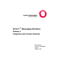
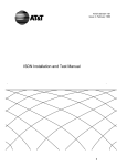
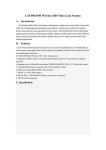
INTUITY Messaging Solutions
Release 5 Centrex Integration
7
Hardware Installation for Centrex Switch Integration with the 202T Modem
Overview
Hardware Installation for Centrex
Switch Integration with the 202T
Modem
7
Issue 1
January 2001
Page 7-1
7
Overview
This chapter describes:
■
The 202T modem
■
Connecting to the multi-port serial circuit card
■
Cabling the voice ports
Purpose
This chapter provides information on the hardware connections required to
integrate any Lucent™ I NTUITY™ MAP (multi-application platform) system with a
Centrex switch using a 202T modem.
INTUITY Messaging Solutions
Release 5 Centrex Integration
7
Hardware Installation for Centrex Switch Integration with the 202T Modem
Distance Requirements
Issue 1
January 2001
Page 7-2
Distance Requirements
A Centrex switch integration requires installation of a 202T modem only if the
distance between the Lucent INTUITY system and the switch is greater than15.3 m
(50 ft), per RS-232 standard. If the distance is 15.3 m (50 ft) or less, for Northern
Telecom (Nortel) DMS-100 and SL-100 integrations, no modem is required, and a
direct-connect configuration can be used. See Chapter 8, ‘‘Hardware Installation
for Integration with Direct Connection or Customer- Supplied Modem’’.
For a Lucent 5ESS® switch, direct connection is not an option. Either a modem or
the 3A SMSI translator must be used. See Chapter 4, ‘‘Hardware Installation for
5ESS Switch Integration with the 3A Translator’’. However, if the distance is 9.7
km (6 mi) or greater, the 5ESS switch cannot be integrated with a 3A SMSI
translator. A 202T modem must be used instead.
Hardware
Two versions of the 202T modem are in use:
■
Motorola 202T modem
■
AT&T 202T Dataphone modem
Refer to the following drawings of the 202T modem when installing the switch
integration hardware.
Motorola 202T Modem
Figure 7-1 shows the front and Figure 7-2 shows the back of the Motorola 202T
modem.
Figure 7-1.
Motorola 202T Modem (Front View)
INTUITY Messaging Solutions
Release 5 Centrex Integration
7
Issue 1
January 2001
Hardware Installation for Centrex Switch Integration with the 202T Modem
Hardware
Figure 7-2.
Page 7-3
Motorola 202T Modem (Back View)
AT&T 202T Dataphone
Figure 7-3 shows the front and Figure 7-4 shows the back of the AT&T 202T
Dataphone modem.
2
1
h2in2tfr RPY 071897
1.
Figure 7-3.
Status lights
2.
Test switches
AT&T 202T Dataphone Modem (Front View)
INTUITY Messaging Solutions
Release 5 Centrex Integration
7
Issue 1
January 2001
Hardware Installation for Centrex Switch Integration with the 202T Modem
Connecting to the Multi-Port Serial Circuit Card
Page 7-4
3
1
2
h2in2tbk RPY 071897
1.
Figure 7-4.
To the Lucent system
2.
Power supply cord
3.
To the switch
AT&T Dataphone 202T Modem (Back View)
Connecting to the Multi-Port Serial
Circuit Card
Use this configuration only if the distance between the Lucent INTUITY system and
the switch is greater than15.3 m (50 ft).
Hardware Required
Use the following hardware:
■
Multi-port serial circuit card installed in the MAP
■
4.3-m (14-ft) modular 6-wire cable (D6AP — provided with multi-port serial
circuit card)
■
RS-232 6-25 pin terminal/printer adapter (DTE)
■
202T modem
■
M8K (or M13F) cable connector for integrations using an AT&T 202T
modem (not needed for the Motorola connection through the telco port)
Figure 7-5 shows the configuration for the integration when the 202T modem is
connected to the multi-port serial circuit card on a Lucent INTUITY MAP system.
INTUITY Messaging Solutions
Release 5 Centrex Integration
7
1.
2.
3.
4.
5.
Issue 1
January 2001
Hardware Installation for Centrex Switch Integration with the 202T Modem
Connecting to the Multi-Port Serial Circuit Card
Serial interface circuit card
Octopus cable
RS232 6-25 pin DTE adapter
202T modem
DW8 cable
Figure 7-5.
6.
7.
8.
9.
Page 7-5
Smart jack (green for Motorola; black for AT&T
Demarcation point
3002 data circuit
Switch
Connecting from the Multi-Port Serial Circuit Card on the Lucent INTUITY
System to the Switch
Installing the Hardware
NOTE:
Before installing the integration hardware, set the switch options on the
202T modem. See Chapter 6, ‘‘Setting the 202T Modem’’.
Use this procedure to configure the hardware for a Centrex switch integration
when connecting to the multi-port serial circuit card on the Lucent INTUITY system
(Figure 7-5).
1. Attach one end of the 4.3-m (14-ft) modular 6-wire cable into the
connector being used on the multi-port serial circuit card on the Lucent
INTUITY system.
NOTE:
The port used must correspond with the port indicated in the
Serial Ports field on the Serial Interface window. For more
information about this window, see ‘‘Setting the Serial Interface
Parameters’’ in Chapter 9, ‘‘Lucent Intuity Administration for Centrex
Switch Integration’’.
INTUITY Messaging Solutions
Release 5 Centrex Integration
7
Issue 1
January 2001
Hardware Installation for Centrex Switch Integration with the 202T Modem
Connecting to the Multi-Port Serial Circuit Card
Page 7-6
2. Attach the other end of the 4.3-m (14-ft) modular cable into the RS-232
6-25 pin DTE adapter.
3. Attach the RS-232 adapter into the female connector in the back of the
202T modem.
4. Plug the power supply cord for the 202T modem into an AC electrical
outlet.
5. Determine your next step. If you are connecting to:
■
An AT&T Dataphone 202T modem, complete the following Steps a
through c:
a. Attach one end of the M8K (or M13F) cable connector to the
male RS-232 connector in the back of the AT&T Dataphone
202T modem.
b. Attach the other end of the M8K (or M13F) adapter to the
bottom of the 829 channel interface unit at the demarcation
point.
NOTE:
For information about possible connections from the
202T modem to the switch, see User’s Manual 202T
Modem (999-102-1421S).
■
A Motorola 202T modem, continue with “Connecting the Motorola
202T Modem Telco Port,” below. Do not use the M8K (or M13F)
cable connector.
INTUITY Messaging Solutions
Release 5 Centrex Integration
7
Issue 1
January 2001
Hardware Installation for Centrex Switch Integration with the 202T Modem
Connecting the Motorola 202T Modem Telco Port
Page 7-7
Connecting the Motorola 202T Modem
Telco Port
Use Figure 7-6 to connect the Motorola 202T modem telco port.
2
5
1
9
6
3
1 2 3 4 5 6 7 8
7
4
8
TELCO
h1in202t RPY 071897
1.
2.
3.
4.
5.
Transmit pair to service provider
BL/W (blue-white) of 4-pair wire
W/BL (white-blue) of 4-pair wire
D8W modular connector
W/GN (white-green) of 4-pair wire
Figure 7-6.
6.
7.
8.
9.
GN/W (green-white) of 4-pair wire
103A or 104A connecting block (or equivalent)
RJ-45 telco connector on rear of modem
Receive pair from service provider
Connection Diagram for the Motorola 202T Modem Telco Port
INTUITY Messaging Solutions
Release 5 Centrex Integration
7
Hardware Installation for Centrex Switch Integration with the 202T Modem
Cabling the Voice Ports
Issue 1
January 2001
Page 7-8
Cabling the Voice Ports
For information about cabling the voice ports from the Lucent INTUITY system, see
Chapter 3, “Making Cable Connections,” in the system installation for your
platform.