1
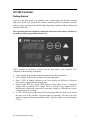
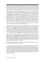
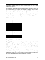
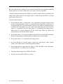
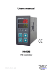
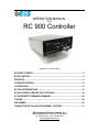
OPERATION MANUAL
FOR
RC 900 Controller
TABLE OF CONTENTS
GETTING STARTED ........................................................................................... 2
RATE CONTROL................................................................................................. 4
PROFILES ........................................................................................................... 5
CASCADE CONTROL......................................................................................... 8
CALIBRATION................................................................................................... 14
RC 900 SOFTWARE MAP................................................................................. 16
RC900 CONTROLLER DEFAULT SETTINGS.................................................. 18
RC900 REMOTE COMMAND SUMMARY ........................................................ 24
TABLES............................................................................................................. 28
PID PRIMER ...................................................................................................... 29
TUNING THE PID VALUES FOR NORMAL CONTROL ................................... 31
Environmental Stress Systems, Inc.
21089 Longeway Road Sonora, CA, USA 95370
Tel. 209.588.1993 Fax 209.588.1997
[email protected]
RC 900 Controller
Getting Started
If you are like most people, you probably want to begin using your RC900 controller
right away. Before you begin please read this manual carefully to familiarize yourself
with the proper operation of the RC900. Begin by getting aquainted with the display and
functions of the keys.
The controller has been completely configured and tested at the factory and there is
no need to modify any parameters before use.
Take a moment to familiarize yourself with the front panel of the controller. It is
composed of the following components:
•
•
•
•
•
Upper Display: Indicates the actual temperature of the thermal platform.
Lower Display: Indicates the set point or desired temperature.
Delta T LED: If lighted, indicates in the lower display the difference in degrees
between the set point and actual temperature.
Output LEDs: The four output LEDs indicate which output if any is energized.
Output LED #1 indicates heat. Output LED #2 indicates cool. Output LED #3
indicates the refrigeration compressor is operating. Output #4 LED indicates remote
communications is occurring.
% OUT LED: The percentage output LED when lighted indicates in the lower display
the duty cycle of the currently energized output in percentage. The duty cycle only
applies to outputs utilizing proportional control. Typically output # 1 heat and output
#2 cool.
RC 900 Operation Manual 1/2001
2
•
•
•
View Key: The VIEW key is used to change what values are currently displayed.
Normally, the typical view is thermal platform temperature in the upper display and
set point or desired temperature in the lower display. Pressing the view key will scroll
through additional displays. The first press of the VIEW key changes the display to
show sensor # 2 or user device probe temperature in the upper display. This is
indicated by a Pr 2 (probe #2) in the lower display. The next press will display the
difference in degrees between the desired set point and current thermal platform
temperature in the lower display. The DELTA T LED will light. The next press will
display the output duty cycle in percentage in the lower display. The % OUT LED
will light. The next press will show the temperature selected units in (C or Celsius) in
the lower display. A final press will return the display to the normal operation mode.
The VIEW key is also used to return to the normal operation display from within any
of the configuration menu displays.
MENU key: The MENU key is used only when changing factory default parameters.
This will be covered in later chapters.
START/STOP key: This key is only used to start and stop ramp and soak profiles.
Profiles will be covered in a later chapter. If the START/STOP key is accidentally
pressed, an LED next to the START/STOP key will flash and the display will change.
Press the START/STOP key twice to return to the normal operation display.
If you have not already done so, turn the controller on using the POWER switch on the
front of the instrument chassis. The red STOP lamp should be lighted. Take a few
minutes to familiarize yourself with the display. Press the VIEW key to scroll through the
various displays. Use the UP and DOWN arrow keys to raise and lower the set point.
Using the VIEW key, make sure that you are in the normal operation display; the upper
display should show the thermal platform temperature and the lower display shows the
current set point. Using the UP or DOWN arrow keys, raise or lower the set point to the
desired temperature. When you are ready for the thermal platform to begin heating or
cooling, press the START switch on the front of the instrument chassis for a moment and
then release it. The START switch enables the thermal failsafe system. If for any reason
the thermal platform heats up beyond a safe operating point, the failsafe thermostat
attached to the thermal platform will disable the heating circuit. Anytime that the heating
circuit is disabled the red STOP lamp on the front of the instrument chassis will be
lighted. Momentarily pressing the START switch will enable the heating circuit.
The thermal platform should begin heating or cooling depending on whether the new set
point is above or below the current thermal platform temperature. The RC900 utilizes
proportional control of the outputs to minimize overshoot and provide precise and stable
temperature control.
RC 900 Operation Manual 1/2001
3
Rate Control
The RC900 is capable of controlling the rate of change of the thermal platform. For most
users this is probably not an issue. However, if your device can be damaged by rapid
changes in temperature (most thermal platforms have a 10 to 30 degree C per minute
maximum rate of change) then you may want to take advantage of this feature. Up till
now, we have explained how to operate the controller from the main or “home” display.
In order to activate the advanced features, it will be necessary to leave the home display
and enter the configuration menus. The default settings for the RC900 are stored in
several different menus. A complete menu map with all of the factory default settings is
located at the end of the manual.
To set the RC900 up for controlled rate of temperature change it is necessary to enter the
GLOBAL menu and enable the RAMP feature.
WARNING: ONLY CHANGE THE MENU SETTINGS THAT YOU ARE
INSTRUCTED TO ALTER! CHANGING OTHER PARAMETERS MAY CAUSE
THE CONTROLLER TO OPERATE IMPROPERLY AND OR MALFUNCTION.
To enter the GLOBAL menu from the home display, press the UP and DOWN arrow
keys simultaneously for at least three (3) seconds or until you see the display change.
Note: If no further keypad activity takes place for 60 seconds, the display will
automatically revert back to home. Pressing the VIEW key at any time while in the
configuration menus will also return you to the normal operation display.
The display should show one of the four (4) menus. The menus are as follows:
InPt
•
•
•
•
OtPt
9LbL
COM
INPUT Menu: The INPUT menu displayed InPt covers all of the sensor input
parameters
OUTPUT Menu: The OUTPUT menu displayed OtPt covers all of the heating and
cooling output parameters.
GLOBAL Menu: The GLOBAL menu displayed 9LbL covers all of the global setup
parameters.
COMMUNICATIONS menu: The COMMUNICATIONS menu displayed COM
covers all of the remote communications setup parameters.
NOTE: Typically, when you enter the menus, the InPt (INPUT) menu is the first one
displayed. However, if one of the other three (3) menus is displayed, scroll through the
menus by pressing the UP or DOWN arrow key until you see 9LbL (GLOBAL) shown
in upper display and SEt (SET) shown in lower display. Now press the MENU key to
display the first parameter in the GLOBAL menu. Continue to press the MENU key to
scroll through the different parameters in the menu until you see OFF (OFF) shown in
the upper display and rP (RAMP) shown in the lower display. Using the UP and DOWN
RC 900 Operation Manual 1/2001
4
arrow keys, change the upper display to read StPt (SETPOINT). Press the MENU key
again to set the rate of change. You should see the factory default setting of 100 or a
previously entered rate value shown in the upper display and rAtE (RATE) shown in the
lower display. Press the DOWN arrow to set the desired maximum rate of temperature
change in degrees C per minute. Press the VIEW key to return to the home display. You
have now programmed the RC900 to change the thermal platform temperature at a rate of
10 degrees C per minute. This rate of change will be used every time a new set point is
entered unless you enter a new rate value or set the rate control to “OFF “in the
GLOBAL menu.
PROFILES
The RC900 is capable of programming and running a three (3) temperature and three (3)
soak period profile. The profile can be repeated up to 255 times. A typical profile might
have the thermal platform start at room temperature, ramp at a specific rate of
temperature change to a high temperature, soak at the high temperature for a given period
of time, ramp to a low temperature, soak at the low temperature for a given period of
time, and return to room temperature. At the end of a ramp and soak profile, you can
program the RC900 to either “hold” the final set point temperature, or to turn the heating
and cooling outputs “off” after the last soak period ends
The Profile is made up of a maximum of eight (8) STEPS. Each STEP is assigned a type
and then any data particular to the type of STEP selected. For example, a STEP that is
defined as a StPt (set point) type initiates a ramp to a new set point and must contain the
new set point value and the ramp rate. Likewise, a STEP defined as a SoAH (soak) type
must contain a value that defines the length of time of the soak period at temperature in
Hours, Minutes, and Seconds. The second to last or seventh (7th) step is always used to
choose the number of profile repeats or loops. You can repeat the profile from 0 to 255
times. The last STEP or eighth (8th) is always defined as an End (end) type and can be set
to HoLd (hold) or OFF (off). If the End STEP is set to HoLd, then the RC900 will hold
the thermal platform at the last set point temperature. If set to OFF then the RC900 will
turn off the heat and cool outputs and show OFF in the lower display when the last soak
period has ended.
Profile Programming:
It is very simple to program a ramp and soak profile from the front panel of the RC900.
From the “home” display (current set point in lower display and platform temperature in
upper display), press the MENU key once. You should see OPEr (OPERATION) shown
in the lower display and SYS shown in the upper display. Press the UP or DOWN arrows
until Pro9 (PROGRAM) is shown in the upper display. Press the MENU key again and
you should see StEP (STEP) shown in the lower display and 1 (the number 1) in the
upper display. If a 1 is not shown in the upper display, press the DOWN arrow until it is.
To view the STEP type for STEP #1 press the MENU key once. You should see StPt
(SET POINT) in the upper display and StYP (STEP TYPE) in the lower display. The
RC 900 Operation Manual 1/2001
5
default type for Step #1 is always StPt (set point). Press the MENU key again to see the
first set point. SP will be in the lower display with a value in the upper display denoting
the first set point temperature. Use the UP or DOWN arrow keys to raise or lower the
value for the first set point. Press the MENU key again to display the ramp rate. rAtE
(RATE) will be shown in the lower display with a value in the upper display denoting the
rate of change. Use the UP or DOWN arrow keys to raise or lower the ramp rate value.
Press the MENU key again to return to the StEP (step) display. You are now ready to
enter values for step # 2. Using the UP arrow key change the number in the upper display
to 2. Press the MENU key to show the step type screen. Step #2 is usually a soak type
step. SoAH (SOAK) should be shown in the upper display. If it isn't, use the UP or
DOWN arrow key to set Step #2 type to SoAH. Press the MENU key to advance to the
Hour (hours) display. Using the UP or DOWN arrow keys, set the number of hours for
the soak. If the soak is to be less than 1 hour then enter a zero (0) for hours. Press the
MENU key to advance to the Min (minutes) screen. Repeat the process until you have set
minutes and seconds for the step # 2 soak period. You have now successfully entered all
of the values for the first ramp and soak segment. Repeat the above process to enter new
set points, ramp rates and soak times for the remaining two (2) ramp and soak segments.
This will use the first six (6) of the available eight (8) steps.
The second to last step, step # 7 is used to enter the number of profile repeats and the step
number to return to at each repeat. In most cases you will want to return to step # 1 at
each repeat. You can repeat a ramp & soak profile from 0 up to 255 times. The step type
for step # 7 is always JMP (JUMP). Press the MENU key to advance to the JStP (JUMP
TO STEP) display. You should see JStP in the lower display and 1 in the upper display.
In most cases you will want the profile to return to the first step (step # 1) each time it
repeats. You can have your ramp and soak profile return to any step you want from step 1
to 6. This is selected in at the JStP (JUMP to STEP) prompt. However, in almost every
case you will want to return to step # 1 every time you repeat a ramp & soak profile. The
last step, step # 8 is always an End (END) type step. However you can choose to set the
END type to be either a HoLd (HOLD) or OFF(OFF) type. A HOLD type will hold the
thermal platform at the last set point of the profile (typically step # 5) indefinitely. If
OFF is selected for the END type then the RC900 will turn of the heat and cool outputs
once the soak period for the last set point has ended. OFF will be shown in the lower
display when the profile has finished running.
When you finished programming all eight (8) steps of the ramp and soak profile, press
the VIEW key to return to the “home” display.
To run a ramp and soak profile, press the START/STOP key once. You will see the
start/stop LED begin to flash. This indicates that the RC900 is in standby mode, ready to
run the profile. You will see StEP (STEP) in the lower display and 1 in the upper display.
Pressing the START/STOP key again will initiate the ramp & soak profile. The start/stop
LED will be lighted continuously and the controller will begin driving the thermal
platform to the first set point temperature. During a profile, pressing the START/STOP
key once will temporarily hold the profile. Pressing the START/STOP key again twice
will restart the profile.
RC 900 Operation Manual 1/2001
6
Note: If at any time while you are entering values into the RC900 controller and there is
no keypad activity for 1 minute, the RC900 will automatically revert back to the “home”
display.
The table below shows a typical ramp and soak profile chart. Making a chart or graph of
the desired profile is very helpful when programming the ramp & soak profile.
STEP NUMBER
1
STEP NUMBER
2
STEP NUMBER
3
STEP NUMBER
4
STEP NUMBER
5
STEP NUMBER
6
STEP TYPE
SET POINT
STEP TYPE
SOAK
STEP TYPE
SET POINT
STEP TYPE
SOAK
STEP TYPE
SET POINT
STEP TYPE
SOAK
SET POINT VALUE
100
HOURS
1
MINUTES
30
SET POINT VALUE
-50
HOURS
0
MINUTES
45
SET POINT VALUE
20
HOURS
1
MINUTES
15
STEP NUMBER
7
STEP TYPE
JUMP
JUMP TO STEP
1
STEP NUMBER
8
STEP TYPE
END
END TYPE
HOLD
RC 900 Operation Manual 1/2001
RAMP RATE
10
SECONDS
0
RAMP RATE
15
SECONDS
0
RAMP RATE
10
SECONDS
0
JUMP COUNT
3
7
Cascade Control
Temperature control applications with long thermal lag times between the heat or cool
source and the point where the temperature is being measured cannot be controlled
accurately with conventional single loop control methods. For this reason the primary
temperature sensor is located in the thermal platform as close to the source of heating and
cooling as possible. This approach works well for precise temperature control of the
thermal platform with minimal overshoot. However, some components due to their size,
shape, heat dissipation, or physical construction can experience an unacceptable
difference in temperature from that of the thermal platform. Simply moving the sensor
from the thermal platform to the device under test cannot eliminate this error. Doing so
will introduce thermal lag and cause the temperature control to become unstable.
A simple but labor intensive way to eliminate the temperature error is to manually adjust
the set point of the thermal platform until the desired device temperature is reached. This
can be effective if you are testing the identical type of device repetitively. Unfortunately,
if the device changes in mass and or heat dissipation then additional manual adjustment
of the set point will be required to eliminate varying thermal errors.
Cascade control eliminates the need for manual set point adjustment by adding an
additional sensor attached to the device and using software to automatically eliminate
thermal error while still maintaining precise control with minimal overshoot. The RC900
is equipped with a second device sensor and the necessary software to provide cascade
control. The second sensor is always active as a read only device sensor input, but the
cascade software must be enabled and the hardware configured before it can be used as a
temperature control sensor.
Cascade control is a sophisticated approach to process control and requires careful set up
to function properly. It is recommended that you use it only if your application needs it
and you understand completely the proper set up procedure.
To enable cascade control it is necessary to make hardware and software changes to
the RC900.
Hardware Configuration for Cascade Control
The thermocouple sensors must be switched so that sensor #1 becomes the device sensor
and sensor #2 becomes the thermal platform sensor. In normal control, sensor #1 is
attached to the thermal platform and sensor #2 is attached to the device under test. For
cascade control, sensor #1 must be attached to the device under test and sensor # 2 must
be attached to the thermal platform.
Sensors 1 and 2 can be re-configured for cascade control by unplugging sensor #1 from
the input 1 socket and unplugging sensor #2 from the input 2 socket. Power down the
RC900 before switching sensors to avoid a “sensor fail” condition that will occur if the
sensors are disconnected during operation. A “sensor fail” condition self corrects when
RC 900 Operation Manual 1/2001
8
the sensors are re-connected and the RC900 is powered off and then back on again. Plug
sensor #1 into the input #2 socket and plug sensor # 2 into the input #1 socket. The
RC900 is now hardware configured for cascade control. Proceed to the software
configuration.
Warning: Sensor connections should only be reversed when using cascade control.
For normal control, make sure sensors 1 is connected to input 1 and sensor 2 is
connected to input 2.
Software Configuration for Cascade Control
To enable cascade control in software it is necessary to enter the GLOBAL menu. See the
above chapter Rate Control for details on how to enter and navigate menus. In the
GLOBAL menu scroll down until you see CntL (CONTROL) in the lower display and
nor (NORMAL) in the upper display. Use the UP or DOWN arrow key to change the
upper display to CSCd (CASCADE). Press the MENU key again and verify that CSAC
(CASCADE ACTION) is set to dir (DIRECT). If it isn’t, use the UP or DOWN arrow
key to set it to dir. Press the MENU key to enter the change. Press the VIEW key to
return to the home display. Cascade control is now enabled.
Be sure the second device probe (now sensor input #1) is connected to the device
under test at a point where accurate temperature measurement is desired. The
device probe should be positively secured to the device under test by mechanical
means such as a screw and washer assembly. Remember that the second device
probe is now a part of the closed loop temperature control system. Failure to
connect the second device probe or a poor thermal connection will cause unstable
control or thermal runaway!
It is now necessary to change the Proportional, Integral, and Derivative (PID) variables
for proper cascade control. To change the PID settings in is necessary to enter the SYS
(system) menu. Press the MENU key once and you should see SYS in the lower display
and OPEr (OPERATION) in the upper display. Press the UP arrow until you see PidA
(PIDA) in the upper display. Press the MENU key and set the following PIDA
parameters using the UP and DOWN arrows to change values and the MENU key to
advance between menu items:
PIDA
PB1A 20
RE1A 0.1
RA1A 0.5
After the last PID setting press the MENU key until you see the PidA in the upper
display. Press the UP arrow key to advance to PidB in the upper display. Press the
MENU key again and set the following PIDB parameters using the technique outlined
above:
RC 900 Operation Manual 1/2001
9
PIDB
PB1B
RE1B
RA1B
CT1B
PB2B
RE2B
RA2B
CT2B
DB B
30
0.10
0.5
1.0
2
0.25
0.5
5.0
0
Note: The above values are recommended starting settings. Your specific application may
require adjustment of these values. Consult the factory if you need help in setting cascade
PID values.
Press the VIEW key to return to the home display. The final values that must be entered
are the rL2 (range low input sensor #2) and rH2 (range high input sensor #2) These
values can be found in the InPt (INPUT) menu. The values for rL2 and rH2 represent
the high and low platform temperature limits beyond the set point that the thermal
platform can be driven to in order to eliminate a temperature gradient between the set
point and the actual device temperature. In other words, if the set point is 100 degrees C
and you have set the rL2 and rH2 values to minus 10 (-10) and plus 10 (+10)
respectively, then the controller can force the thermal platform temperature by as much as
10 degrees beyond the set point. The platform can be driven to 110 degrees C if
necessary to force the device to the 100 degrees C set point. This allows the controller to
automatically eliminate the thermal error caused by temperature gradients between the
platform and the device. If the temperature gradient decreases over time, the controller
will automatically compensate and adjust the thermal platform temperature to hold the
device under test at the set point temperature. The recommended value for rL2 and rH2
is 10. This number can be raised or lowered slightly if necessary but we have found it to
be satisfactory in most cases.
Note: The changing of menu values can be very easily accomplished via the serial or
GPIB remote interface. Some users find this more convenient than entering menu values
from the front panel. See the Communications chapter for more details on remote
computer interfaces. A sample string to set the rL2 and rH2 values is shown below:
= RL2 10
= RH2 10
RC 900 Operation Manual 1/2001
10
Communications
The RC900 comes standard with EIA-232 serial communications and optional factory or
field installable GPIB (IEEE-488) remote communications.
The EIA 232 communications uses a 3-wire system. A typical cable diagram is pictured
below:
RC900 9 pin connector
Pin #2
Pin #3
Pin #5
IBM compatible 9 pin connector
Pin #2
Pin #3
Pin #5
RC900 9 pin connector
Pin #2
Pin #3
Pin #5
IBM compatible 25 pin connector
Pin #3
Pin #2
Pin #7
The RC900 uses the following EIA-232 serial communications parameters:
Baud rate
Data bits
Start bits
Stop bits
Parity
Protocol
9600
8
1
1
None
Xon/Xoff
Communications is carried out using ASCII characters in either upper or lower case
Command Structure
? Returns the value of a specific command from the RC900
= Sets a specific prompt in the RC900 to a specific value
Information bracketed by < > indicates a description so <space> or <sp> indicates an
ASCII character hex 20 (a space made by the space bar).
For example, if you want to send a new set point of 100 to the RC900, the ASCII string
would look like the following:
=<space>SP1<space>100<carriage return>
RC 900 Operation Manual 1/2001
or
= SP1 100
11
To read the current temperature of sensor # 1 use the following string:
?<space>C1<carriage return>
or
?
C1
Programming Note: The RC900 writes all new set point commands from the remote
interface to non-volatile EEPROM memory. The EEPROM is good for 10,000 writes.
When sending a new setpoint using the remote communications, it is a good practice to
disable the non-volatile feature of the RC900 thereby prolonging the useful life of the
EEPROM. To command the RC900 not to write new set points received form the remote
interface to EEPROM send the following string:
=<space>SPEE>space>1<carriage return>
or
= SPEE 1
You can check that the RC900 is not writing new set points to EEPROM by sending the
following string:
?<space> SPEE<carriage return>
or
? SPEE
If the RC900 returns a “1” then writing set point to EEPROM has been disabled. If it
returns a “0” then it will write set points to the EEPROM. It is only necessary to send the
"SPEE" command at the beginning of a session unless the RC900 is powered down. After
every power down, the RC900 always resets to a state whereby new set points received
via the remote interface will be written to non-volatile memory.
Brief Command Summary List
Command
Description
Type
Sample
C1
C2
RP
Sensor #1 temperature
Sensor #2 temperature
Enable Ramp Rate Mode
Read only
Read only
Read & Write
RATE
Ramp rate in deg. C/min
Read & Write
SP1
Enter New Set Point
Read & Write
HIP
Disable heat output
Read & Write
Enable heat output
Read & Write
Disable cool output
Read & Write
Enable cool output
Read & Write
Set point not to EEPROM
Read & Write
?<sp> C1<cr>
?<sp> C2<cr>
=<sp>RP<sp>2<cr>
?<sp>RP<cr>
=<sp>RATE<sp>15<cr>
?<sp>RATE<cr>
=<sp>SP1<sp>100<cr>
?<sp>SP1<cr>
=<sp>HIP<sp>0<cr>
?<sp>HIP<cr>
=<sp>HIP<sp>100<cr>
?<sp>HIP<cr>
=<sp>LOP<sp>0<cr>
?<sp>LOP<cr>
=<sp>LOP<sp>-100<cr>
?<sp>LOP<cr>
=<sp>SPEE<sp>1<cr>
?<sp>SPEE<cr>
LOP
SPEE
RC 900 Operation Manual 1/2001
12
Note: The HIP & LOP commands are used to temporarily turn off and on and or examine
the current state of the heat and cool outputs. The ability to turn off outputs is helpful
when precise measurements need to be made and a passive (not heating or cooling)
thermal platform is desirable while taking measurements. Note that to re-enable the heat
output a positive (+100) HIP value is needed and to re-enable the cool output a minus 100
(-100) LOP value must be entered.
GPIB (IEEE-488) remote communications
The RC900 can be fitted with factory or field installable GPIB (IEEE-488) remote
communications. When the GPIB communications option is installed, the EIA-232
communications interface remains usable. However, only one communication interface
can be used at a time. A switch on the rear of the cabinet next to the remote computer
interface connectors must be set to either EIA-232 or GPIB communications.
The default address for the GPIB interface is set to 704.
A different address can be set remotely via the GPIB interface. For example, to set a new
GPIB address of 720, do so in the following manner:
“SYST:COMM:GPIB:ADDR 20”
Note: Provide a 0.1 second delay after sending the new address before querying the new
address setting.
To query the new address setting use the following command:
“SYST:COMM:GPIB:ADDR?”
The GPIB port on the RC900 should respond with a “20”
If the RC900 responds with the correct new address then it should be saved to nonvolatile memory. Do so with the following command:
“*SAV<sp>0”
Sample HP Basic program to change the GPIB address from 704 to 720
10
20
30
40
50
60
70
80
OUTPUT 704;”SYST:COMM:GPIB:ADDR 20”
WAIT 0.1
OUTPUT 720;”SYST:COMM:GPIB:ADDR?”
ENTER 720;A$
DISP A$
WAIT 3
OUTPUT 720;”*SAV 0”
END
RC 900 Operation Manual 1/2001
13
The command strings used by the GPIB interface are identical to the ones used for the
EIA-232 interface. See the previous section on EIA-232 communications for details
about command strings.
A simple HP Basic sample program showing some typical command strings is shown
below:
10
20
30
40
50
60
70
80
90
OUTPUT 704;”= SPEE 1” *
set point changes not saved to EEPROM
OUTPUT 704;”= SP1 85” *
sends a new set point of 85 degrees C
OUTPUT 704;”= RATE 15”*
sets rate of change to 15 degrees C/minute
OUTPUT 704;”? C1”
*
queries channel # 1 temperature
ENTER 704;A
DISP “SENSOR #1 TEMPERATURE = “;A
WAIT 2
GOTO 40
END
Calibration
The RC900 is factory calibrated and under normal conditions should not require
calibration in the field. However, if is determined that calibration becomes necessary, use
the following procedure.
The RC900 is calibrated from the CAL (calibration) menu. To carry out proper
calibration, the following equipment is necessary:
•
•
Type J reference compensator with reference junction at 32 degrees F/0 degrees C, or
Type J thermocouple calibrator set at 32 degrees F/0 degrees C.
Precision millivolt source, 0 – 50mV minimum range, 0.01mV resolution.
Setup and Calibration
1. With the MRTP powered off, remove the cabinet cover and remove the thermocouple
wires
from
terminals
#9
&
#10
and
#19
&
#20.
2. For input #1, connect the millivolt source to terminal #9 (+) and terminal #10 (-) with
20 to 24 gauge copper wire. For input #2, connect the millivolt source to terminal #19
(+) and terminal #20 (-) using 20 to 24 gauge copper wire.
3. Apply power to the unit and let it warm up for 15 minutes. After the warm up period
is complete, enter the CAL (calibration) menu by pressing the UP and DOWN arrow
keys simultaneously for at least 6 seconds or until you see PLOC in the upper display
and FctY in the lower display. Press the UP arrow until you see CAL in the upper
RC 900 Operation Manual 1/2001
14
display and FctY in the lower display. Note: Input #1 is referred to as A and input #2
is referred to as B. Always calibrate input #1 or A first followed by input #2 or B.
4. Press the MENU key to enter the calibration menu. At the A 50 prompt, or the B 50
prompt and with the 50 millivolt source connected to the proper terminals, wait 10
seconds for stabilization and then press the UP arrow key to enter a YES in the upper
display. Disregard all other prompts. Press the MENU key to save the new data and to
advance to the next prompt.
5. At the A 00 prompt or the B 00 prompt, enter 0.00mV from the millivolt source to the
proper terminals. Allow 10 seconds to stabilize. Press the UP arrow key to enter a
YES in the UPPER display. Disregard all other prompts. Press the MENU key.
6. At the tc prompt, disconnect the millivolt source, and connect the reference
compensator or thermocouple calibrator to terminal #9 (+) and terminal #10 (-). If
using a compensator, turn it on and short the input wires. When using a J type
calibrator, set it to simulate 32 degree F/0 degrees C. Allow 10 seconds for
stabilization. Press the UP arrow key to change the UPPER display to YES.
Disregard all other prompts. To conclude the calibration process, press the VIEW key
to return to the home display.
Restore Calibration
If you make a mistake while calibrating your RC900, the rSt (restore) prompt near the
end of the calibration menu can be used to restore the original factory calibration settings.
At the rSt prompt, press the UP arrow key to show a YES in the UPPER display. Press
the MENU key and the original factory values are restored.
RC 900 Operation Manual 1/2001
15
RC 900 Software Map
Press the two arrow keys simultaneously for 3 seconds to reach the 4 SET (SEt) menus and use
the arrows to select a menu
INPUT (InPt) Press the MENU key to enter and navigate
Input 1 ( In1) Values: see table 2
Range Low 1 ( rL1
Range High 1 ( rH1)
Calibration 1 (CAL1)
Input Filtering 1 (Ftr1)
Input 2 ( In2) Values: see table 2
Range Low 2 ( rL2)
Range High 2 ( rH2)
Calibration 2 (CAL2)
Filter 2 (Ftr2)
OUTPUT (OtPt) Press the MENU key to enter and navigate
Output 1 ( Ot1) Value: Heat ( Ht)
Output 2 ( Ot2) Value: Cool ( CL)
Cooling Action (CACn)
Alarm 2 ( AL2)
Outpout 3 ( Ot3)
Interval Time ( Int) Value: in minutes
Compressor OFF Time (CoFF) Value: in minutes
GLOBAL (9LbL) Press the MENU key to enter and navigate
Temperature units ( C_F) Values: Celsius ( °C) or Fahrenheit ( °F)
Sensor Failure Output Function (FAIL)
Error, Latching Enable ( Err)
Software Control (CntL) Values: normal ( nor) or cascade (CSCd)
Cascade action (CSAC)
Algorithm (AL9O)
Event Input 1 Function ( Ei1)
Alarm Annunciation (Anun)
Power limit percentage for Output 2, cooling ( LoP) Value: -100
Power limit percentage for Output 1, heating (HiP) Value: 100
Auto-tune Set Point % (AtSP)
Ramping initiation ( rP) if not off, then RATE appears
Power Outage (Pout) Values: see table 4
Guaranteed Soak Deviation (9Sd)
COMMUNICATIONS (COM) Press the MENU key to enter and navigate
Baud Rate (bAUd) Values:300, 600,1200, 2400, 4800, 9600 bits/s
Data (dAtA)
Protocol (Prot) Choices: Xon/Xoff ( on), Modbus (Mod), Full (FULL)
Instrument (IntF) Choices: EIA-232 (232), EIA-485 (485)
RC 900 Operation Manual 1/2001
16
Press the MENU key once to reach the OPERATION (OPEr) menu and twice to reach the
AUTO-TUNE ( AUt) menu
OPERATION (OPEr) Use the arrow keys to navigate and the MENU key to enter
SYSTEM ( SyS)
IF SOFTWARE CONTROL IS IN NORMAL MODE
PID A (PidA)
Proportional Band 1, heating (Pb1A)
Reset or Integral 1, heating (rE1A)
Rate or Derivative 1, heating (rA1A)
Cycle Time 1, heating (Ct1A)
Proportional Band 2, cooling (Pb2A)
Reset or Integral 2, cooling (rE2A)
Rate or Derivative 2, cooling (rA2A)
Cycle Time 2, cooling (Ct2A)
Dead Band A (db A)
PID B (Pidb) not accessible
IF SOFTWARE CONTROL IS IN CASCADE MODE
PID A (PidA)
Proportional Band 1, cascade (Pb1A)
Reset or Integral 1, cascade (rE1A)
Rate or Derivative 1, cascade (rA1A)
PID B (Pidb)
Proportional Band 1, heating (Pb1b)
Reset or Integral 1, heating (rE1b)
Rate or Derivative 1, heating (rA1b)
Cycle Time 2, heating (Ct1b)
Proportional Band 2, cooling (Pb2b)
Reset or Integral 2, cooling (rE2b)
Rate or Derivative 2, cooling (rA2b)
Cycle Time 2, cooling (Ct2b)
Dead Band B (db b)
PROGRAM (Pro9)
SEE PROFILE SECTION OF THE MANUAL
AUTO-TUNE ( AUt) Value: OFF
Press the two arrow keys simultaneously for 6 seconds to reach the 3 FACTORY (Fcty) menus
and use the arrows to select a menu
FRONT PANEL LOCKOUT (PLOC) Press the MENU key to enter and navigate
Lockout (LOC) Values: see table 3
Diagnostic (diA9)
Calibration ( CAL)
RC 900 Operation Manual 1/2001
17
RC900 Controller Default Settings for LN2 or LCO2 Plates
INPUT
SET
OUTPUT
SET
GLOBAL
SET
COMM
SET
T
IN1
HT
OT1
0
C
C_F
9600
BAUD
-99
RL1
CL
OT2
-1
FAIL
8N
DATA
130
RH1
NOR
CACN
NLA
ERR
ON
PROT
0
CAL
OFF
AL2
NOR
CNTL
232
INTF
0
FTR1
OFF
OT3
PID
AL90
T
IN2
1
COFF
NO
EI1
OFF
RSP
OFF
ANUN
-99
RL2
-100
LOP
130
RH2
100
HIP
0
CAL2
90
ATSP
0
FTR2
OFF
RP
CONT
POUT
2
GSD
RC 900 Operation Manual 1/2001
18
RC900 controller default PID A settings for LN2 or LCO2 Plates
PIDA
OPER
15
PB1A
0.05
RE1A
0.01
RA1A
1.0
CT1A
15
PB2A
0.05
RE2A
0.5
RA2A
5.0
CT2A
0
DB A
RC 900 Operation Manual 1/2001
19
RC900 Controller Default Settings for MRTP
INPUT
SET
OUTPUT
SET
GLOBAL
SET
COMM
SET
T
IN1
HT
OT1
0
C
C_F
9600
BAUD
-75
RL1
CL
OT2
-1
FAIL
8N
DATA
130
RH1
NOR
CACN
NLA
ERR
ON
PROT
0
CAL
OFF
AL2
NOR
CNTL
232
INTF
0
FTR1
CC
OT3
PID
AL90
T
IN2
1
COFF
NO
EI1
OFF
RSP
OFF
ANUN
-75
RL2
-100
LOP
130
RH2
100
HIP
0
CAL2
90
ATSP
0
FTR2
OFF
RP
CONT
POUT
2
GSD
RC 900 Operation Manual 1/2001
20
RC900 controller default PID A settings for MRTP
PIDA
OPER
30
PB1A
0.10
RE1A
0.5
RA1A
1.0
CT1A
2
PB2A
0.25
RE2A
0.5
RA2A
5.0
CT2A
0
DB A
RC 900 Operation Manual 1/2001
21
RC900 Controller Default Settings for TEMP
INPUT
SET
OUTPUT
SET
GLOBAL
SET
COMM
SET
T
IN1
HT
OT1
0
C
C_F
9600
BAUD
-10
RL1
CL
OT2
-1
FAIL
8N
DATA
130
RH1
NOR
CACN
NLA
ERR
ON
PROT
0
CAL
OFF
AL2
NOR
CNTL
232
INTF
0
FTR1
CC
OT3
PID
AL90
T
IN2
1
COFF
NO
EI1
OFF
RSP
OFF
ANUN
-10
RL2
-100
LOP
130
RH2
100
HIP
0
CAL2
90
ATSP
0
FTR2
OFF
RP
CONT
POUT
2
GSD
RC 900 Operation Manual 1/2001
22
RC900 controller default PID A settings for TEMP
PIDA
OPER
1
PB1A
0.30
RE1A
0
RA1A
1.0
CT1A
1
PB2A
0.20
RE2A
0.30
RA2A
1.0
CT2A
-5
DB A
RC 900 Operation Manual 1/2001
23
RC900 Remote Command Summary
Name
Description
Read (?)
Write(=)
Value range
C1
Channel # 1 temperature value
? C1
Input 1 range
C2
Channel # 2 temperature value
? C2
Input 2 range
CAL
Lock out calibration menu
? CAL
= CAL value
0=unlocked/1=read
2=locked/Default = 0
CAL1
Input # 1 calibration offset
? CAL1
= CAL1 value
-999 TO +999
Default = 0
CAL2
Input # 2 calibration offset
? CAL2
= CAL2 value
-999 TO +999
Default = 0
CF
Select temperature units for display
? CF
= CF value
0 = F, 1 = C
Default = 1
CNTL
Control mode; used to enable cascade control
software; hardware changes also necessary
? CNTL
= CNTL value
0=normal; 1=cascade
Default = 0
COM
Lockout communication menu
? COM
= COM value
0=unlocked; 1=read;
2=locked; Default=0
CSAC
Cascade action; use when control function is set to
cascade
? CSAC
= CSAC value
0=direct action;
1=reverse; Default=0
CSP
Current profile set point; profile mode
? CSP
Input 1 range
CT1A
Output # 1 cycle time for heating; PID set A
? CT1A
= CT1A value
0.1 to 999 seconds
Default 1.0 seconds
CT2A
Output # 2 cycle time for cooling; PID set A
5 second minimum for electromechanical device
? CT2A
= CT2A value
CT1B
Output # 1 cycle time for heating; PID set B
? CT1B
= CT1 value
0.1 to 999 seconds
Default 5.0 seconds
0.2
0.3 to 999 seconds
Default 1.0 seconds
CT2B
Output # 2 cycle time for cooling; PID set B
5 second minimum for electromechanical device
? CT2B
= CT2B value
0.2 to 999 seconds
Default 5.0 seconds
DATE
Factory test date
? DATE
XXYY; XX = week;
YY = year
DBA
Dead band PID set A; do not use with proportional
control enabled
? DBA
= DBA value
-999 to +999
Default = 0
DBB
Dead band PID set B; do not use with proportional
control enabled
? DBB
= DBB value
-999 to +999
Default = 0
RC 900 Operation Manual 1/2001
24
DEV
Temperature deviation between set point & thermal
platform temperature
? DEV
Delta between SP and
platform temperature
DIAG
Lockout diagnostics menu
? DIAG
= DIAG value
0=unlocked; 1=read;
2=locked; Default=0
EJC
Elapsed repeat jump count cycles; profile mode
? EJC
0 to 255
ER2
Communications error codes
? ER2
0 to 39; see table 1
FAIL
Bumpless output action if sensor fails; 1-100%
heats;-1 to –100% cools
? FAIL
= FAIL value
-100 to +100%
Default = -1% cool
FTR1
Input # 1 signal filter to smooth rapidly changing
display; typically not needed with thermocouples
? FTR1
= FTR1
-60 to +60 seconds
Default = 0
FTR2
Input # 2 signal filter to smooth rapidly changing
display; typically not needed with thermocouples
? FTR1
= FTR1
-60 to +60 seconds
Default = 0
GLBL
Lockout the global menu
? GLBL
= GLBL value
0=unlocked; 1=read;
2=locked; Default = 0
GSD
Guaranteed soak temperature deviation in degrees;
Applied in profile mode
? GSD
= GSD value
0 to 999
Default = 0
HIP
Output # 1 (heating) power limit in percentage
? HIP
= HIP value
0 to +100
Default = 100
HOLD
Simulates a HOLD key press; profile mode
? HOLD
= HOLD value
0 = not in HOLD
1 = a HOLD
IN1
Input # 1 thermocouple sensor type
? IN1
= IN1 value
1to 5; see table 2
Default = 3
IN2
Input # 2 thermocouple sensor type
? IN2
= IN2 value
1to 5; see table 2
Default = 3
INPT
Lockout the input menu
? INPT
= INPT value
0=unlocked; 1=read;
2=locked; Default = 0
INSP
Examine the cascade control platform set point;
Used when control action is set to cascade mode
? INSP
-999 to +999
Default = -10 to +10
LOC
Front panel keypad lockout
? LOC
= LOC value
0 to 3; see table 3
Default = 0
LOP
Output # 2 (cooling) power limit in percentage
? LOP
= LOP value
0 to -100
Default = -100
OT1
Output # 1 action type
? OT1
= OT1 value
0=heat; 1= cool
Default = 0
OT2
Output # 2 action type
? OT2
0=heat; 1= cool
RC 900 Operation Manual 1/2001
25
OTPT
Lockout output menu access
= OT2 value
? OTPT
= OTPT value
Default = 1
0=unlocked; 1=read;
2=locked; Default = 0
OTY4
Examine serial communication type
? OTY4
0=none; 19=EIA-232
Default = 19
PB1A
Proportional band width for heating output # 1; PID
set A
? PB1A
= PB1A value
0 to 999
Default = 14
PB2A
Proportional band width for cooling output # 2; PID
set A
? PB2A
= PB2A value
0 to 999
Default = 14
PB1B
Proportional band width for heating output # 1; PID
set B
? PB1B
= PB1B value
0 to 999
Default = 14
PB2B
Proportional band width for cooling output # 2; PID
set B
? PB2B
= PB2B value
0 to 999
Default = 14
PIDA
Lockout access to PID set A
? PIDA
= PIDA value
0=unlocked; 1=read;
2=locked; Default = 0
PIDB
Lockout access to PID set B
? PIDB
= PIDB value
0=unlocked; 1=read;
2=locked; Default = 0
PWR
Percent output power for currently operating output;
1 to 100% = heating; -1 to –100% = cooling; 0=off
? PWR
-100 to +100%
RA1A
PID Rate for output # 1 (heating); PID set A
Units represented in minutes
? RA1A
= RA1A value
0.00 to 9.99 minutes
Default = 0.05
RA2A
PID Rate for output # 2 (cooling); PID set A
Units represented in minutes
? RA2A
= RA2A value
0.00 to 9.99 minutes
Default = 0.05
RA1B
PID Rate for output # 1 (heating); PID set B
Units represented in minutes
? RA1B
= RA1B value
0.00 to 9.99 minutes
Default = 0.05
RA2B
PID Rate for output # 2 (cooling); PID set B
Units represented in minutes
? RA2B
= RA2B value
0.00 to 9.99 minutes
Default = 0.05
RE1A
PID Reset for output # 1 (heating); PID set A
Units represent Repeats per Minute
? RE1A
= RE1A value
0.00 to 9.99 R/M
Default = 0.28
RE2A
PID Reset for output # 2 (cooling); PID set A
Units represent Repeats per Minute
? RE2A
= RE2A value
0.00 to 9.99 R/M
Default = 0.28
RE1B
PID Reset for output # 2 (cooling)
Units represent Repeats per Minute
? RE1B
= RE1B value
0.00 to 9.99 R/M
Default = 0.28
RE2B
PID Reset for output # 2 (cooling)
Units represent Repeats per Minute
? RE2B
= RE2B value
0.00 to 9.99 R/M
Default = 0.28
RH1
Set point span range high limits for input sensor # 1
Temperature units are in degrees C.
? RH1
= RH1 value
Std 130C Opt 200C
Default = 130 deg C
RC 900 Operation Manual 1/2001
26
RH2
Set point span range high limits for input sensor # 2
Temperature units are in degrees C. Note: See
section on cascade software special settings
? RH2
= RH2 value
Std 130C Opt 200C
Default = 130 deg C
Cascade = 10 deg C
RHS
Run/ Hold status for ramp & soak; profile mode
? RHS
0=HOLD 1=RUN
RL1
Set point span range low limits for input sensor # 1
Temperature units are in degrees C.
? RL1
= RL1 value
Ambient to –99 C
Default = -99 deg C
RL2
Set point span range low limits for input sensor # 2
Temperature units are in degrees C. Note: See
section on cascade control software special settings
? RL2
= RL2 value
Ambient to –99 C
Default = -99 deg C
Cascade = 10 deg C
RP
Enable the temperature ramp rate feature
? RP
= RP value
0 or 2; 0 = off /2 = on
Default = 0
RATE
SOFT
Ramp rate in degrees per minute. The maximum
ramp rate is limited by the platform performance
Software version revision
? RATE
= RATE value
? SOFT
0 to 999 degrees/min
Default = 100
0 to 26; 0 = A 26 = Z
SP1
Set point for thermal platform temperature
SPEE
Write set point to EEPROM; Set to 0 for remote
communications. Resets to 1 at each power up
? SP1
= SP1 value
? SPEE
= SPEE value
RH1 to RL1 span
No Default
0=write; 1=do not
write; Default = 0
RC 900 Operation Manual 1/2001
27
Tables
Table 1 ER2 command error codes
0
1
2
3
4
5
6
7
8
20
21
22
23
24
25
26
27
28
30
31
32
33
38
39
No error
Transmit buffer overflow
Receive buffer overflow
Framing error
Overrun error
Parity error
Talking out of turn
Invalid reply error
Noise error
Command not found
Prompt not found
Incomplete command line
Invalid character
Number of characters overflow
Input out of limit
Read only command
Write only command
Prompt not active
Request to RUN invalid
Request to HOLD invalid
Command invalid in RUN mode
Command invalid in HOLD mode
Asterisk not allowed
Infinite loop error
Table 2 IN1 & IN2 command values
1
2
3
4
5
J type t/c; 32 to 1500 F/0 to 816 C
K type t/c; -328 to 2500 F/-200 to 1371 C
T type t/c; -328 to 750 F/-200 to 399 C
N type t/c; 32 to 2372 F/0 to 1300 C
E type t/c; -328 to 1470 F/-200 to 799 C
Table 3 LOC command values
0
1
3
No keypad lockout
Lock out SYSTEM, PID & PROGRAM menus
Lock out SYSTEM, PID, PROGRAM menus & UP & DOWN arrow keys (set point lock out)
Table 4 POUT command values
0
1
2
3
4
Continue
Hold
Abort
Idle set point
Reset
RC 900 Operation Manual 1/2001
28
PID Primer
What is PID?
PID stands for Proportional, Integral, and Derivative. The following explanations
describe PID as it applies to the precise control of a process temperature. A process is an
area or zone that is being controlled at or driven to a precise temperature. PID is a control
method or mode that has three functions or variables. The proportional action dampens
process response. The integral corrects for droop. Droop is the difference in temperature
between the process set point and the actual process temperature. The set point is the
desired process temperature. The derivative minimizes overshoot and undershoot.
Overshoot is the amount in temperature units that the process temperature exceeds the
set point before the process stabilizes. Process stabilization is achieved when the set
point and process temperatures are equal over a defined period of time. Undershoot is
the amount in temperature units that the process temperature falls below the set point
before the process stabilizes.
Proportional is the control output effort in proportion to the error from set point. A
control output is a signal action delivered in response to the difference between set point
and process temperature. An output usually controls a heating or cooling action. The
proportional range is referred to as a “band” and is usually measured in temperature units.
If a proportional band of 20 degrees is applied to a process that is 10 degrees below set
point, the heat output would be 50 percent. The lower the proportional band, the higher
the gain. Gain is the amount of amplification used in an electrical circuit. Proportional
band is sometimes referred to as gain. The proportional band or PB is a range in which
the proportioning function of the controller is active. The PB units are usually expressed
in degrees.
Integral is a control action that automatically eliminates droop or offset. Offset is the
same as droop and is the difference in temperature between the process temperature and
the set point. Droop or offset is a typical result when using proportional control. Integral
is also known as “Reset”.
Derivative is the rate of change in a process temperature. Large values prevent overshoot
but can cause sluggishness. It is also known as “Rate”.
What is Cascade?
Cascade as it applies to the precise control of a process temperature is a control algorithm
in which the output of one control loop provides the set point for another loop. A control
loop is a closed system comprised of four basic elements. A process to be controlled, a
temperature sensor, a temperature controller, and energy source. The sensor measures the
process temperature, compares it to the set point and drives an energy source to eliminate
the error. The error is the difference between the set point and actual process
RC 900 Operation Manual 1/2001
29
temperature. The second control loop determines the control action. The control action
is the response of the control output relative to the error between the process temperature
and the set point.
Cascade is used to control a difficult process where minimal overshoot and quick
stabilization are desired. A difficult process is described as a process in which there is
long thermal lag or unacceptable thermal gradients. Thermal lag refers to the time it
takes for the process sensor to measure the effect of an increase or decrease in the heating
or cooling output. Long lag times can be caused by many conditions. Poor sensor location
and or a thermally insulated sensor are two possible causes. A thermal gradient is the
difference in temperature between the device under test (DUT) and the process at
stabilization. A DUT with a large volume or mass, poor thermal conduction, or large and
or varying heat dissipation can cause thermal gradients. These conditions would require
cascade for precise control.
Thermal lag causes a lot of energy to be built up in the process before the sensor can
detect a response. Delayed response results in overshoot and undershoot or oscillations.
Oscillations as applied to process control refer to a state where temperature overshoot
and undershoot continue to occur over a long period of time without diminishing. In other
words, the error between set point and process temperature cannot be eliminated and
stabilization never occurs.
A process with long lag times or thermal gradients cannot be controlled precisely with a
single loop controller because energy would build up and cause thermal oscillations. It
may be possible to reduce the oscillations by using PID settings that minimize overshoot
but the time it would take for the process to reach set point and stabilize would be
unacceptably long.
Cascade utilizes two loops to provide precise control in a long lag time process. The two
loops are described as the inner loop and the outer loop. Each loop has a thermal sensor.
The sensor on the inner loop is located in close proximity to the energy source. An
energy source is typically a heater or coolant supply. The sensor on the outer loop is
located in close proximity to the DUT. The inner loop (energy) sensor is used to prevent
the excessive build up of energy. The outer loop (DUT) sensor is used to provide precise
temperature control of the DUT. Cascade software in the controller is used to drive the
energy output based on the input from the two sensors.
Cascade requires that a temperature range be set for the energy source. A temperature
range is the amount in degrees that the inner loop temperature (energy source) can
exceed the set point in an effort to bring the DUT to the set point with minimal overshoot
and the shortest stabilization time. The range is a relative value based on the current set
point. There is a high setting for the heat energy source and a low setting for the cooling
source. The range high setting is a positive number and the range low setting is a negative
number. The range high and low settings are usually based on the maximum temperature
gradient that you want to eliminate that occurs between the DUT and process when
stabilization first occurs. For example, if a set point of 100 is selected, there may be a
RC 900 Operation Manual 1/2001
30
difference of several degrees between the DUT temperature and the process temperature.
The range setting allows the process to heat up beyond the set point to drive the device to
100 degrees.
The inner and outer loop each have their own set of PID variables to provide precise
control. Each loop must have the correct PID values in order for the cascade to function
properly. The inner loop (energy source) is assigned PID set B (PIDB) and the outer loop
(DUT) is assigned PID set A (PIDA). The inner loop PIDB set is tuned first. Tuning is
the process of entering PID variables and watching the effect on the process until
satisfactory control and stabilization result. Once the inner loop PIDB is set properly,
then the outer loop PIDA set must be tuned.
Tuning the PID Values for Normal Control
Normal control refers to single loop control. Another section will cover tuning PID
values for cascade control. PID values are set at the factory and under normal conditions
should not need to be changed. However, if you determine that your process requires
adjustment of the PID values, or you are using cascade control, you may need to enter
new PID values. There are many good reference books available on PID. This section is
not meant to be an in depth study of PID but simply to provide a basic “hands on”
technique for PID tuning. There are other viable methods of determining good PID
settings but the following method is one that has worked well for us.
Warning! Improperly set PID values can cause erratic process control. Do not attempt to
change the PID values unless you have read and understand the following sections.
The effect of changed PID values on a process is best observed when a large change in
process temperature occurs. For example, if you typically test at 85 degrees then a good
test of PID values would be to observe their effect on overshoot, undershoot and
stabilization time on a process that begins at 25 degrees and ends at 85 degrees. The
greater the temperature change the more accurate the evaluation of the PID values will
be.
Proper PID tuning starts by recording the current PID values for Proportional, Reset and
Rate and then setting the three PID variables Proportional, Reset and Rate to a value of
zero (0).
There are a couple of other system values that need mentioning although they are not a
part of the PID tuning procedure. When setting up a process there are some other terms
that you should be aware of. Dead Band or DB refers to the temperature band around the
set point that determines when the output will shut off. DB is only used in ON/OFF
control. ON/OFF control describes a process that does not use proportional control such
as a home heating and air conditioning system. If PB is set to zero (0) then a value other
than zero (0) must be entered for DB. Without a DB, an ON/OFF process could rapid
RC 900 Operation Manual 1/2001
31
cycle as soon as it hit set point. Since all of our systems utilize proportional control, the
DB value is not important and should be set to zero (0).
Hysteresis is the amount of change in the process temperature that is required to reenergize the control output after it has shut off. This is the temperature in an ON/OFF
process where the output will turn back on again after it has turned off. For example, in
an ON/OFF process when in cooling mode, with a dead band of –1.0 degrees and a
hysteresis of +2.0 degrees you would have the following action:
If the process is at 80 degrees and you enter a new set point for 70 degrees, the cooling
output would turn on until the process reaches 69 (DB of –1.0 degrees) and then it would
turn off. The cooling output would not turn on again until the process temperature
reaches 71 degrees (hysteresis of +2.0 degrees. Note that the hysteresis is measured from
the dead band turn off point and not from the set point. As with dead band, hysteresis is
only a factor when in an ON/OFF control mode. In proportional mode (a PB greater than
zero) hysteresis can be set to zero (0).
Cycle time is the time required for the controller to complete one on-off-on cycle (do not
confuse with ON/OFF control). Cycle time is the period of time that the process
controller can make an adjustment to the output duty cycle based on the error between
set point and process temperature. Duty cycle is the amount of time that the output
remains energized during the cycle time period. What this means is that the controller
will break up the job of controlling the process temperature into little windows of time.
The duration of each time period is determined by the cycle time value. Proportional
control is often based on time and is therefore also referred to as time proportioning
control. This is how it works:
If you have a cycle time of 5 seconds and the PID control calls for an output duty cycle of
50% then the output will be on for 2-1/2 seconds and off for 2-1/2 seconds. The duty
cycle “on time” plus the “off time” will equal the cycle time period. Likewise if the
output duty cycle is 20% then there would be a 1-second on time with a 4 second off
time. The controller is constantly monitoring the error and will adjust the output duty
cycle as necessary for each cycle time period. The shorter the cycle time the more precise
the control. However, very short cycle times can cause electromechanical devices to wear
out prematurely. A good rule of thumb is to use a minimum of a 5-second cycle time for
any output that utilizes an electromechanical device such as a solenoid valve. Devices
such as resistive elements (heaters) can use as short a cycle time as desired because there
are no moving parts to wear. Cycle time for non-electromechanical devices can be 1
second or less.
Burst or zero cross firing is term used to describe a type of control method that can
yield more precise control and longer energy source life. It can only be used with devices
that have no moving parts such as heater elements. Burst firing repeatedly turns on and
off full AC cycles. It is also called zero cross firing because it switches close to the zero
voltage point of the AC sine wave. Burst firing selectively holds or transits AC cycles to
achieve the desire output power level. Burst firing offers a much more precise method of
RC 900 Operation Manual 1/2001
32
control with a maximum of a 1.66-second time base to a minimum 33.3 millisecond time
base. Element life is also prolonged.
In a typical heat cool system, there is a separate set of PID values for the heat output and
the cool output. Output # 1 is typically the heat output and output # 2 is typically the cool
output. PB1 would be the proportional band for output # 1 and PB2 would be the
proportional band for output # 2. In cascade control where you have two sets of PID
values for each output you would have PB1A and PB1B. PB1A is proportional band
output # 1 set A. PB1B would be proportional band output # 1 set B. A chart later in this
section will show all of the abbreviations with their explanations.
Tuning PID variables always starts with setting the proportional band for the output you
are tuning with the Reset and Rate values set to 0. Since the different PID values are
related, it is best to work with one value at a time. Once one value has been set properly,
the next value can be adjusted, observing the effect it has on the process. If you are
tuning the heat output then you will be setting proportional band # 1 first. Start with the
process at room temperature. Enter a starting PB value of 10 and enter a set point of the
highest temperature your process will typically be run at such as 100 degrees. Watch the
process heat up and observe the overshoot, undershoot, and if the oscillations decrease
over time or stay the same. It will be necessary to cool the process back down to room
temperature when you change the PB value and to send the process back to 100 degrees
to accurately observe the effect of the change on the process. Study the charts below and
adjust the PB value as necessary to get the desired results.
Note: A strip chart recorder or other data recorder such as a data logger is very helpful in
determining the effect that a change in a PID setting has on the overall process. In the
absence of automated data recording equipment, a watch with a second counter and a pad
of notepaper can be used. Record temperatures in as short of intervals as is practical for
the most accurate results. You can create your own charts similar to the ones at the end of
the section using a “connect the dot” technique.
Once the PB value has been set correctly you should have minimal overshoot, minimal
droop and minimal oscillations. Proceed to setting the Reset (Integral) value. Carefully
increase the Reset value until the droop is eliminated. A good starting point would be a
value of about 0.20. A Reset setting that is too high will re-introduce oscillations into the
process. A Reset value that is to low will either not eliminate the droop or eliminate it
over a very long period of time.
Once the Reset has been set correctly, you should observe a single minimal overshoot,
followed by a single minimal undershoot, with a droop that is eliminated in a short period
of time, followed by a stable process temperature with very little error. At this point you
can proceed to setting the Rate (Derivative) value. The Rate or Derivative value can have
a large and undesirable effect on the process if it is set too high. Very carefully increase
the Rate value to eliminate the initial minimal overshoot and undershoot. If at any time
oscillations are re-introduced into the process then reduce the Rate value. A good starting
Rate value would be 0.05. In some cases it is best to leave the Rate value set to 0. If after
RC 900 Operation Manual 1/2001
33
setting the PB and Reset correctly you observe oscillations when a Rate value is added,
return the Rate value to 0.
As a general rule, any time there are unacceptable oscillations observed in a process, then
one of the PID values is set incorrectly. The advantage of setting one value at a time in
the exact order outlined above is that it is easy to identify which PID value is introducing
the undesirable oscillations and to make the necessary adjustment.
Once the PID values have been correctly set for output # 1, proceed to set the output # 2
values in the same manner as outlined above. Keep in mind that the graphs provided
would be inverted when you are tuning for process temperatures below ambient.
PID abbreviations table
PB1A
RE1A
RA1A
CT1A
PB2A
RE2A
RA2A
CT2A
DBA
Output 1 proportional band set A
Output 1 reset set A
Output 1 rate set A
Output 1 cycle time set A
Output 2 proportional band set A
Output 2 reset set A
Output 2 rate set A
Output 2 cycle time set A
Dead band set A
PB1B
RE1B
RA1B
CT1B
PB2B
RE2B
RA2B
CT2B
DBB
Output 1 proportional band set B
Output 1 reset set B
Output 1 rate set B
Output 1 cycle time set B
Output 2 proportional band set B
Output 2 reset set B
Output 2 rate set B
Output 2 cycle time set B
Dead band set B
Tuning the PID Values for Cascade Control
Tuning the PID values for cascade control mode is similar to normal control tuning. The
main difference is that there are two sets of PID values corresponding to the two sensor
feedback loops. The order is also critical. In cascade mode you always tune the B set of
PID values first. The B set of PID values is assigned to the inner loop (energy source).
After the B set is tuned, proceed to the A set. The A set is assigned to the outer loop
(DUT). The B set has a discreet set of values for output 1 and output 2 respectively. The
A set has a single set of PID values.
Cascade control enables a difficult process to be controlled with minimal overshoot and
rapid stabilization. A long lag time process cannot be precisely controlled with a single
loop approach because a lot of energy can build up before a response can be detected by
the process sensor. Built up energy causes overshoot and oscillations.
RC 900 Operation Manual 1/2001
34
Be aware that the Rate variable for set A (outer loop) (RA1A) can introduce instability
into the process even more so that usual. Use a value of zero (0) if possible.
Using the charts provided, tune the PID B set to achieve stable control as outlined in the
charts. Once stable control of the energy source is achieved tune the PID A set to get
good control at the device.
Cascade control checklist:
•
Be sure that the sensor # 1 and sensor # 2 are connected to the proper location on the
process. In normal control, sensor # 1 is attached to the energy source and sensor # 2
is attached to the DUT. In normal control, sensor # 2 acts only as a monitoring sensor
to indicate DUT temperature. It is not a part of the control loop. In cascade control,
sensor # 1 is attached to the DUT and sensor # 2 is attached to the energy source.
Both sensors are critical components of the control loop. Failure to connect the
sensors properly will result in erratic control.
•
Be sure that sensor # 1 is securely attached to the DUT in a location that best matches
the desired temperature monitoring point as outlined in the test procedures.
•
Be sure that sensor # 2 is connected to the energy source.
•
Set up the RC900 for “cascade” under “control type” and “direct” under “cascade
action” in the Global menu. See RC900 operation manual.
•
Set the high and low range values for input # 2 (RL2 and RH2) in the Input menu.
Factory default is –10 for RL2 and +10 for RH2.
•
Tune inner loop (energy source) PID set B values.
•
Tune the outer loop (DUT) PID set A values.
RC 900 Operation Manual 1/2001
35
Typical normal control application. DUT is low profile and responds quickly to changes
in thermal platform temperature
controller
sensor #2
DUT sensor
sensor #1
enegy source sensor
DUT
thermal platform
(energy source)
100
100
Typical cascade control application. DUT is high profile and responds slowly to
changes in thermal platform temperature. Normal control would allow unacceptable
thermal gradients. Moving single loop sensor to DUT would allow energy build up that
would result in oscillations and instability.
sensor #1
DUT sensor
controller
sensor #2
enegy source sensor
DUT
thermal platform
(energy source)
100
100
RC 900 Operation Manual 1/2001
36
RC 900 Operation Manual 1/2001
37
RC 900 Operation Manual 1/2001
38
RC 900 Operation Manual 1/2001
39