1
Eagle STP and IP7 Secure Gateway Assemblies
–48VDC
Power Source
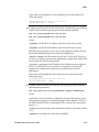
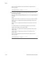
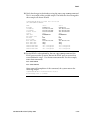
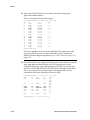
This section verifies that the –48VDC Power Source has been labeled and
connected correctly to the corresponding system frame's Fuse and Alarm
Panels (FAPs). Your system may not include all of the frames described. For
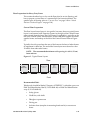
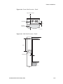
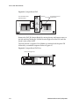
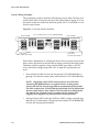
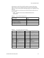
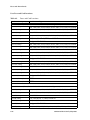
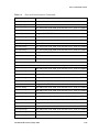
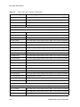
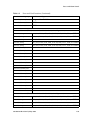
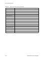
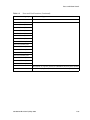
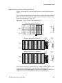
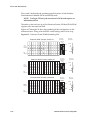
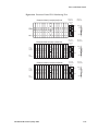
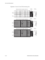
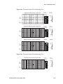
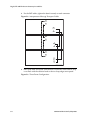
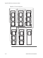
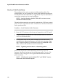
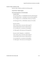
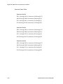
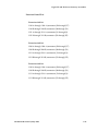
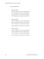
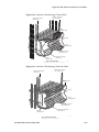
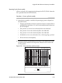
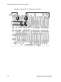
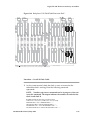
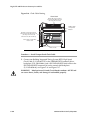
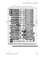
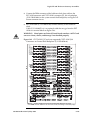
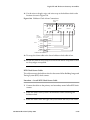
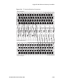
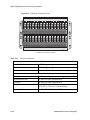
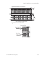
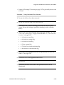
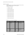
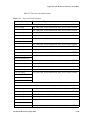
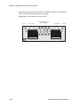
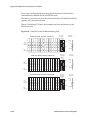
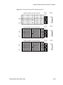
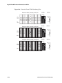
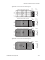
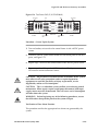
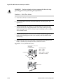
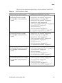
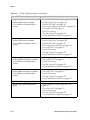
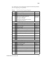
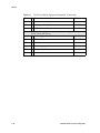
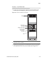
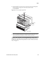
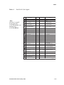
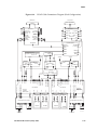
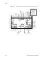
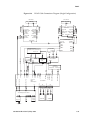
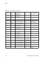
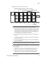
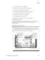
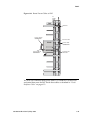
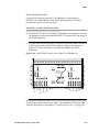
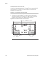
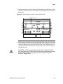
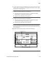
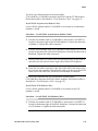
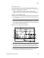
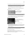
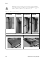
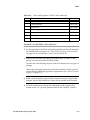
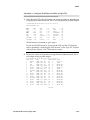
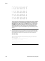
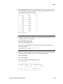
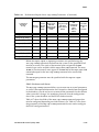
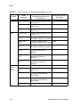
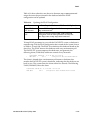
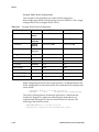
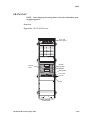
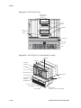
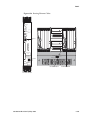
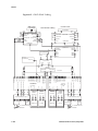
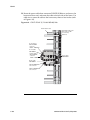
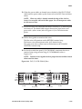
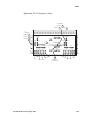
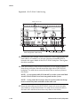
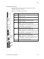
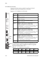
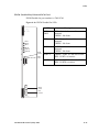
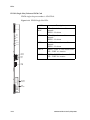
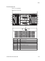
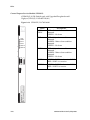
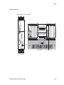
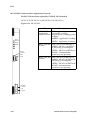
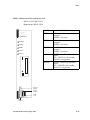
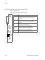
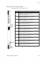
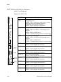
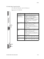
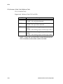
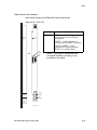
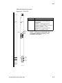
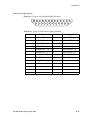
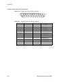
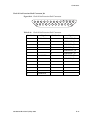
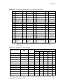
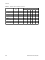
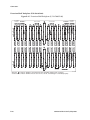
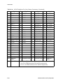
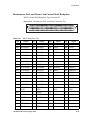
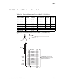
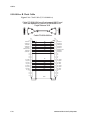
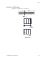
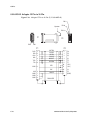
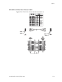
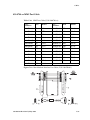
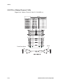
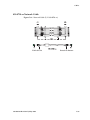
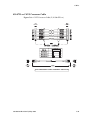
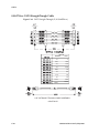
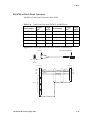
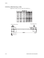
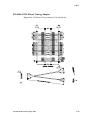
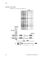
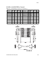
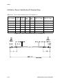
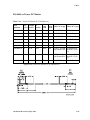
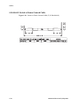
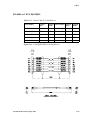
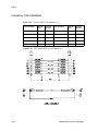
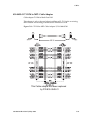
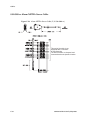
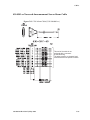
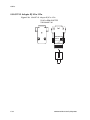
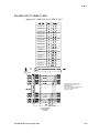
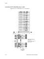
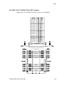
test points used in the following procedures, see Figure 5-72 and Figure 5-72.
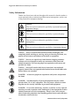
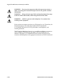
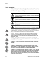
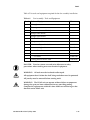
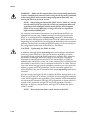
DANGER: No commercially AC powered equipment may be used or
placed within 7 ft. of –48V equipment. This may create a shock or
current loop that can be severely hazardous to personnel and
equipment.
WARNING: Do not carry exposed metal keys or tools in pockets or on
belts when working on or around electronic equipment. Do not wear
metal rings, watches, or jewelry on wrists or hands when working on
any electronic equipment or other related electrostatic sensitive
components. Always wear a wrist strap or other electrostatic protection
when handling printed circuit cards and other electrostatic sensitive
devices.
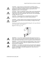
WARNING:
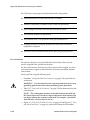
following:
Before performing the following procedures do the
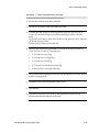
•
Ensure that no power is being provided to the system from the
–48VDC power source, such as a power board
•
Ensure that no circuit cards are installed in the shelves
•
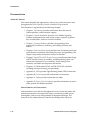
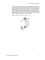
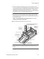
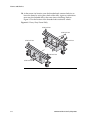
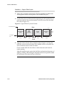
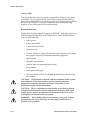
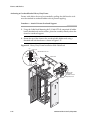
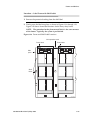
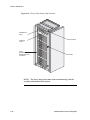
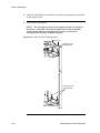
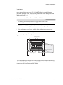
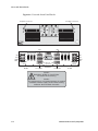
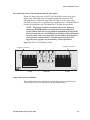
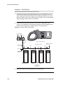
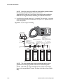
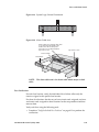
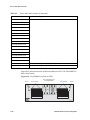
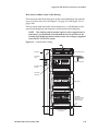
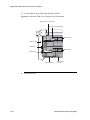
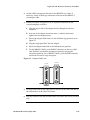
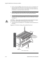
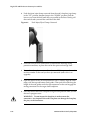
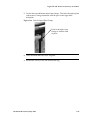
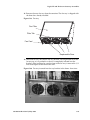
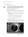
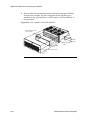
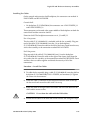
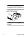
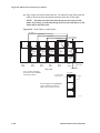
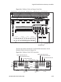
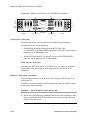
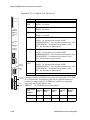
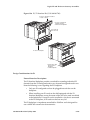
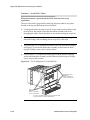
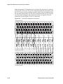
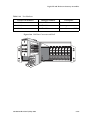
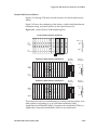
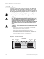
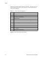
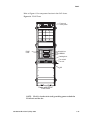
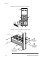
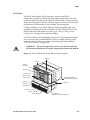
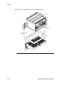
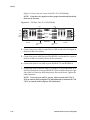
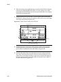
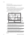
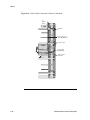
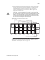
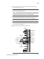
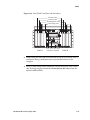
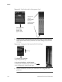
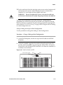
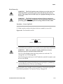
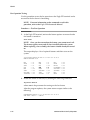
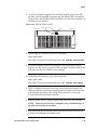
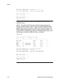
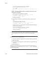
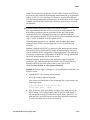
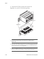
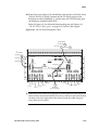
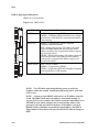
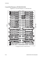
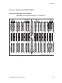
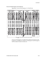
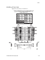
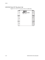
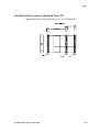
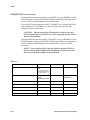
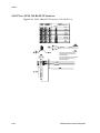
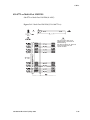
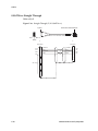
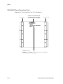
Remove all fuses from the fuse and alarm panels, see Figure 5-71.
•
Recheck wiring and connections for proper polarity
Figure 5-71. Fuse and Alarm Panels
Fuse and Alarm Panel
P/N 870-2320-01
Screw
Fuse holders
Fuse holders
PWR TEST
POINT
POS
CRITICAL
Screw
PWR TEST
POINT
POS
MAJOR
PWR ALARM A
PWR ALARM B
OP/MAINT
PWR TEST
POINT
NEG
FAP_DB_A
FUSE BANK A
MINOR
FUSE
FAP_JB
FAP_AB
PWR TEST
POINT
NEG
FAP_DB_B
FUSE BANK B
TEKELEC
e30 fapfront fuses
5-162
910-4601-01 Revision D, May 2005