1
EOAP
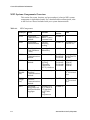
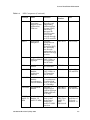
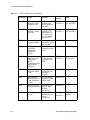
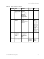
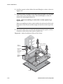
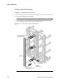
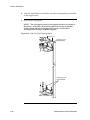
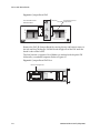
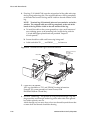
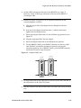
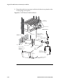
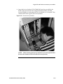
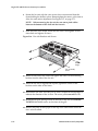
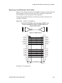
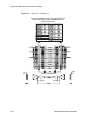
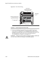
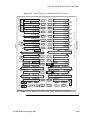
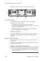
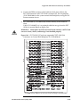
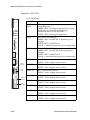
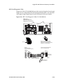
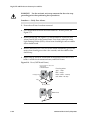
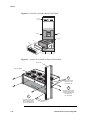
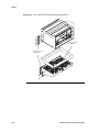
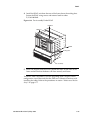
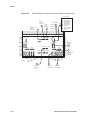
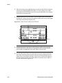
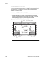
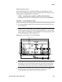
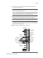
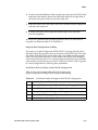
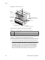
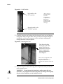
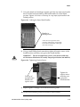
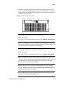
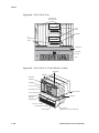
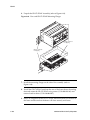
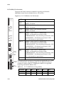
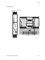
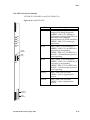
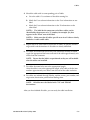
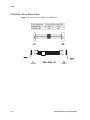
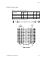
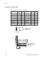
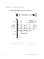
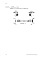
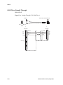
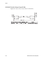
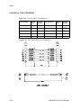
17. Install the fan power cables (P/N 830-0609-01). Plug the GR-376 EOAP
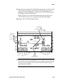
end of one fan power cable on the connector designated FAN A, PWR A
located at the top center of the GR-376 EOAP backplane. Plug the FAN
end of the cable onto the FAN A PWR connector of the fan assembly and
tighten the connector.
18. Tighten the cable connectors.
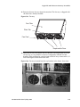
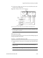
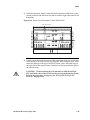
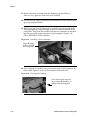
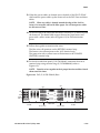
19. Plug the EOAP end of the second FAN power cable (P/N 830-0609-01)
onto the connector marked FAN B PWR B located in the center lower
middle of the EOAP backplane. Plug the FAN end of the cable onto FAN B
PWR connector on the fan assembly.
20. Tighten all cable connectors.
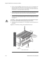
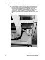
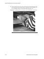
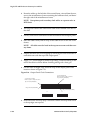
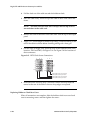
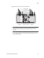
21. Route the FAN B PWR cable down to the bottom tie-down rod and across
the rod to the right side of the GR-376 EOAP backplane.
22. Use cable ties to secure the cable to the tie-down rod every three or four
inches.
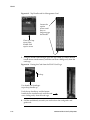
23. Wrap the fan power cables with fiber paper at the point they are routed
around the edge of the GR-376 EOAP shelf toward the frame rails.
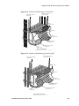
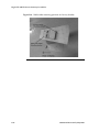
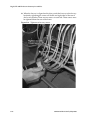
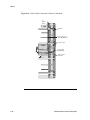
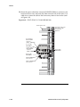
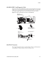
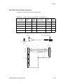
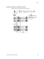
24. Form and dress the fan power cables with the other cables. Use cable ties
to secure the cable to the traverse arm. The fan cable installation is
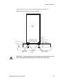
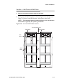
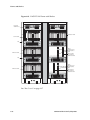
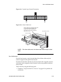
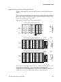
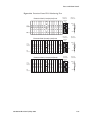
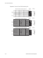
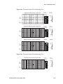
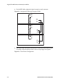
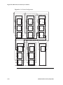
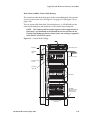
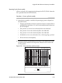
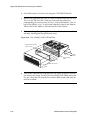
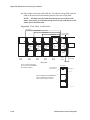
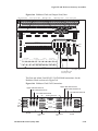
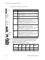
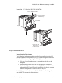
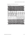
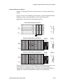
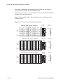
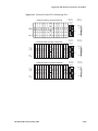
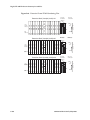
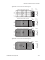
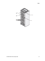
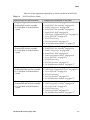
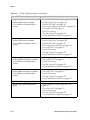
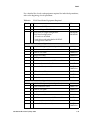
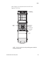
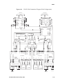
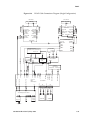
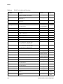
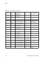
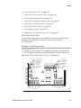
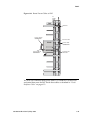
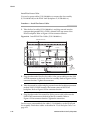
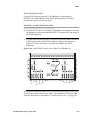
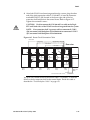
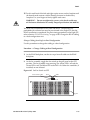
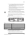
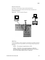
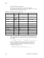
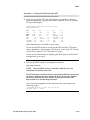
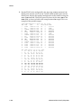
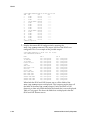
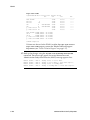
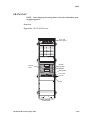
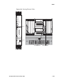
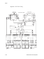
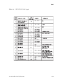
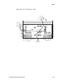
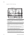
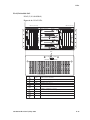
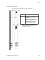
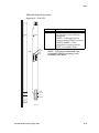
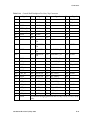
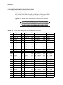
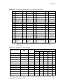
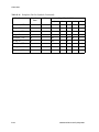
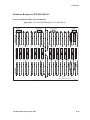
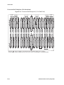
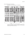
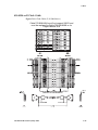
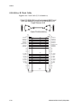
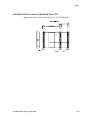
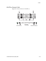
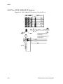
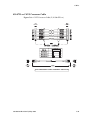
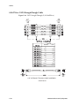
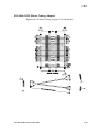
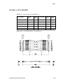
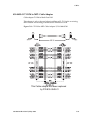
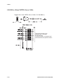
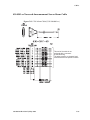
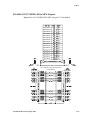
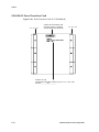
complete. Refer to Figure 6-65 for GR-376 EOAP Cabling Configuration.
6-160
910-4601-01 Revision D, May 2005