1
Santa Clara University
DEPARTMENT of COMPUTER ENGINEERING
Date: June 11, 2003
I HEREBY RECOMMEND THAT THE THESIS PREPARED UNDER
OUR SUPERVISION BY
Benard Farrales and Francis Chan
ENTITLED
Mapping Robot Utilizing Amigobots
BE ACCEPTED IN PARTIAL FULFILLMENT OF THE REQUIREMENTS FOR THE
DEGREE OF
BACHELOR OF SCIENCE IN COMPUTER ENGINEERING
______________________
Dr. Neil Quinn Jr
______________________
Christopher Kitts
______________________
Dr. Daniel Lewis
1
Mapping Robot Utilizing Amigobots
by
Bernard Farrales and Francis Chan
SENIOR DESIGN PROJECT REPORT
Submitted in partial fulfillment of the requirements
for the degree of
Bachelor of Science in Computer Engineering
School of Engineering
Santa Clara University
Santa Clara, California
June 11, 2003
2
Mapping Robot with Activemedia’s Amigobot
Bernard Farrales and Francis Chan
Department of Computer Engineering
Santa Clara University
2003
ABSTRACT
Robots in today’s world are utilized in environments that are
just too dangerous for human intervention. They provide us
eyes, ears, and touch to places we usually see unfit. Our
objective is to provide a cognitive sense of mapping memory to
assist in the explorative endeavors of these environments with
the use of sonar technology. In this paper we utilize sonar
technology to map a room of unknown dimensions along with
autonomous navigational capabilities. Our experiments show
that sonar data can be very inaccurate at very close and far
ranges along with slight angles. We counteract these
inaccuracies with the use of a Gaussian filter and distance
filters. We identified that the sonar works best at a certain
threshold usually ranging from 1200-1500 centimeters which
we have reflected to our filter. This threshold also changes
when the robot is exposed to different environments.
Consequently to make sonar more reliable dynamic thresholds
in combination with a wall following algorithm will keep our
values as accurate as possible and give us a better view of the
real world.
3
Acknowledgements
Special Thanks to
Professor Neil Quinn and Professor Chris Kitts
For their guidance and support on this project
4
TABLE OF CONTENTS
Page
Abstract………………………………………………………….………………………..iii
Chapter 1 Introduction…………………………………………………………………….7
1.1. Background……………………………………………………………………….7
1.2. Project goals……………………………………………………………………...8
1.3. Contributions………………………………………………………………….….8
Chapter 2 System Overview………………………………………………………………9
2.1 Use Cases………………………………………………………………………..10
2.2 Conceptual Model……………………………………………………………….10
2.3 List of Requirements (functional and non-functional)..........................................10
Chapter 3 Software………………………………………………………………………11
3.1 Architectural Diagram…………………………………………………………..11
3.2 Class Descriptions……………………………………………………………….11
3.3 Technologies Used………………………………………………………………14
3.4 Robot Specifications…………………………………………………………….15
Chapter 4 Testing………………………………………………………………………...17
4.1 Test Plan, including test cases…………………………………………………...17
4.2 Test and Experimental Results…………………………………………………...18
Chapter 5 User Manual…………………………………………………………………..22
Chapter 6 Other Issues…………………………………………………………………...24
Chapter 7 Conclusion…………………………………………………………………….26
7.1 Summary of work………………………………………………………………..26
7.2 Project Challenges/Future implementation………………………………………26
7.3 “The big picture”…………………………………………………………………27
References………………………………………………………………………………..28
Appendix A: Mapping Robot Code…………………………………………………...…29
Appendix A.1 Myrobot.cpp………………………………………………………….29
Appendix A.2 Myrobot.h ……………………………………………………………36
Appendix A.2 MappingView.cpp……………………………………………………38
Appendix A.2 MappingView.h …………………………………………….……..42
5
List of FIGURES
Page
Figure 1-1 Activemedia Amigobot Diagram……………………………………………...7
Figure 2-1 Use Case Diagram….......................…………………………………………...9
Figure 2-2 Conceptual Model Diagram…........……………………………………….....10
Figure 3-1 Architectural Diagram…………………………………….……………….....11
Figure 3-2 Gaussian Function…..…………………………………….………………….12
Figure 3-3 Database simulation ..…………………………………….………………….12
Figure 3-4 Movement Statechart.…………………………………….………………….13
Figure 4-1 Test case with Oblong Object in middle of control environment…….….…..19
Figure 4-2 Test case down long hallway….………………………….………………….20
Figure 4-3 Test case down long hallway at different angles...……….………………….20
Figure 4-4 Test case in random room……………………………………………………21
Figure 4-5 Picture of Random room……………………………………………………..21
6
Chapter 1. INTRODUCTION
Our main goal of this project is to allow a robot equipped with sonar sensors to map a
room with unknown dimensions at an unknown origin.
1.1 Background
The primary function of our robot is for us to be able to drop our robot off anywhere in
an unknown room and allow it to navigate throughout the room while incrementally
mapping its pinged sonar values to a 2D plane. The bundled Activemedia software
already provides us with a wide array of functions for our robot; however it lacks the
robust autonomy to actually map an unknown area.
Main Objectives
•
Development of an interface between our mapping software and the robot.
•
Development of an GUI interface and graphical mapping program
•
Development of an algorithm that will be able to filter false sonar readings to our database.
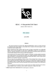
Robot Diagram(1-1):
Activemedia Amigobots©
Antenna, signal amplifier
•
•
8 fixed sonars firing@
25Hz(40ms per sonar)
Sensitivity 10cm–3m(6
inches – 10 feet)
•
Position encoders 2, one at each
motor 9,550 ticker per wheel
revolution 30 ticks per mm
7
1.2 Project Goals
Design
Our main goal here is to do enough research to be able to develop a simple yet robust
algorithm. We attempt to take software engineers approach to this problem, with little or
no knowledge of sonar filtration or localization algorithms, we find ourselves jumping
into unknown territory. It is imperative that our design be as flawless as possible or else
we will be paying dearly in our testing phase trying to work out the bugs.
Implementation
Activemedia has provided an extensive library of access functions to the robot known as
“Aria” which is written in C++. We decided to write the rest of the mapping algorithm,
GUI, and database all in C++ as well to ensure compatibility. Another important concern
for us during the implementation phase is whether will have sufficient time to debug the
whole robot to an acceptable range of precision. It’s not known to us yet at how accurate
the sonar will and how much error we will attain from the inaccurate nature of sonar
technology.
Testing
Different environments may give us very different results, i.e. using sonar in a room full
of loud subwoofers and acoustics will render our readings useless. We will have to
provide enough diversity in our testing phase to ensure that all the algorithms are working
efficiently and give us accurate map values. Finding an area where we will able to
conduct these experiments accurately.
1.3 Contributions
We would like to thank the Santa Clara University Robotics department for the donation
of the amigobot, pc’s, and lab rooms to make this project possible.
8
CHAPTER 2 SYSTEM OVERVIEW
2.1 Use Case(2-1)
robot_control
activates_n_runs
Database
User
Map
views
The “Robot Control” will hold our mapping and movement algorithms that we
programmed into the robot all the user has to do is activate and run the robot. The user
will interact with is the database, which will contain a flat file of x and y values. The
display map will have a visible GUI interface that will graphically display the values in
the database in a visual topological grid.
-User Activates and runs the robot
-User has the option to analyze raw data values in database
-User can visually analyze the map via gui
9
2.2 Conceptual Model(2-2)
MovingAlgorithm
Commands
Robot
SonarVals
Polar to
Rectangular
transformation
X,Y coordinates &
Distance from objects
Database
FilteredVals
Filter
Map
2.3. List of Requirements
•
Sonar/Odometer Equipped robot provided by Activemedia’s Amigobot
•
PC w/ 300Mhz or better w/ open serial port
•
Software Interface to robot MCU
•
Closed controlled static environment to be mapped
•
C++ compiler
10
CHAPTER 3 SOFTWARE
3.1 Architectural Diagram(3-1)
DATABASE
1
1
FILTER
1
1
MAP
1
1
ROBOT
movement
1
3.2
1
Class Descriptions
Database
consists of a 2 dimensional array of (x,y) coordinates. Each value is tagged along with a
probability value determined by our filter.
Filter
The filter is based upon two functions, the first one being a simple distance filter given to
us by the limitations by the sonar. Specifically the sonar will not register if it is too close
or too far from an object and we have accommodated this discrepancy when ever we take
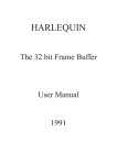
readings with a threshold. The second filter we have implemented is a Gaussian function:
11
(3-2)
After extensive testing of the robots sonar we pinpointed a value in which we
accumulated the best readings and used that as our peak. Hence whenever we took a
value the closer to our peak a higher probability value was tagged onto the sonar
reading to be stored into the database. The end result is a valley of sonar readings to
be stored into database as shown in the next diagram.
(3-3)
12
Hence the end result will be a map consisting of valleys in which we can decide exactly
how much of the “valley” we want to show on the map which will translates to a higher
filtered map the higher probability we choose to use, vice versa.
Map
takes in the filtered values from the database and generates a GUI of a map.
Robot
Command control for our robot which receive and deliver commands sent via wireless
modem.
Movement
Our movement algorithm consists of a wander function as described in the following
state chart.
scan
C
Nothing in front
Move
forward
(3-4)
Something in front
Random
Function
odd
Rotate right
even
Rotate left
C
13
3.3 Technologies Used
•
Aria
o Library functions for the amigobot provided by activemedia that
allows us to communicate with the robot.
•
Activemedia software suite
o Provides us interface to programming and observing the robot.
•
Rhapsody
o C++ UML program used to construct our OMDs and statechart
diagrams.
•
Microsoft Visual C++
o Used to develop our code and run our robot.
•
Amigobots© by Activemedia Robotics
o Robotic unit
o
Specifications included on next page
14
3.4 Robot Specifications
Mapping Amigobot SPEC
•
Physical Characterisitics
o Robot measurements: 33cm X 28cm X 13 cm
o Body clearance: 3 cm
o Weight: 3.6 Kg
o Payload: 1 Kg
•
Construction
o Body: Molded polycrb
o Chassis: 1.6mm fab alum
o Assembly: Allen hex screws (metric)
•
Power
o 12V lead-acid
o Charge 24.2 watt-hr
o Run time: 3+ hours
o Recharge time (trickle) 12 hrs
o Recharge time (hi-cap) 4 hours
•
Mobility
o Drive wheels: 2 solid rubber, with caster balance
o Wheel diameter: 10 cm
o Wheel width: 3cm
o Steering: Differential
o Gear ratio: 19.5:1
o Swing Radius: 33cm
o Turn Radius: 0 cm
o Translate speed max: 750mm/sec
o Rotational speed max: 300 degrees/sec
o Traversable step max: 1.5 cm
o Traversable terrain: all wheelchair accessible
•
Sensors
o Fixed sonar:
15
§
8 total
•
4 forward, 2 at rear, 1 at each side
§
Firing rate 25Hz( 40 ms per sonar)
§
Sensitivity 10cm – 3meters( 6 inches – 10 feet)
•
Note any objects closer than 10 cm are read as 10
cm
§
Problems include external noise and false echoes
§
Limitations: environment must be quiet, flat surfaced, with
minimal reflected surfaces surrounding the perimeter
o Position encoders
§
•
2, one at each motor
•
9,550 ticker per wheel revolution
•
30 ticks per mm
Electronics
o Processor : 20 MHz Hitachi H8
o Position inputs: 4
o Sonar inputs: 1x8(multiplexed)
o Digital I/O: 8-bit logic ports
o A/D: 4@0-5VDC
o Digital timer inputs: 6@ 1microsec resolution
o Comm port: 3 RS-232 serial
o FLASH: 64 KB uP/1MB external
o RAM: 16KB uP
•
Controls and Ports
o Main Power: Robot/accessories power ON/OFF
o Charge: System power/battery recharge
o Reset: Warm reboot/download
o Mortors/Test: Motors/download/self-tests
o Radio: Power and serial
o Speaker: 8-ohm
o Serial comm. Ports: 3 x RS232(Control/System/AUX)
16
CHAPTER 4 TESTING
4.1 Test plan
Sonar
Our first step in testing the robot is to test out its sonar systems and the accuracy of them.
For this we conducted 2 different tests:
I. Comparative Tests of the Sonar data to actual distance of the robot to the wall.
II. Comparative tests of the Sonar data at different angles to a wall to the actual
distance from the sonar sensor to the wall itself
III.
Comparative tests in different locations in a room with e.g. corners, noisy rooms,
and long halls.
IV.
Next series of tests will repeat steps I-III with the use of the filters.
Movement/Mapping
Our second step was to test out our movement algorithm once we had our sonar sensor
data working correctly. The progression of the testing attempted to start with a simple
environment to a highly complex environment so that we can specify the limitations of
the robot, no matter what the case.
I. Mapping of a square enclosed room with 4 walls
II. Mapping of a square enclosed room with a movement algorithm that turns left
only
III. Mapping of a square enclosed room with a movement algorithm which turns
randomly
IV. Mapping of a square enclosed room with wander function with an obstacle
17
V. Mapping of a hallway using the wander function starting from parallel to the
walls
VI. Mapping of a hallway using the wander function starting from a random angle
to the wall.
4.2 Test Results
Sonar
Extensive testing has concluded a few parameters that our design should try to follow.
First of all our best readings came from when the sonar sensor is perpendicular to the
wall it was pinging off of. Slight change in the angles however would throw our readings
off especially at very close and far ranges. Corners also served as a problem for the sonar
as readings that came from them usually read either very close or very far beyond the
actual physical object.
One thing we did notice is that readings from a 120cm – 150cm on average seemed to
give us the best readings. We used values within our threshold Gaussian function as the
peak point. The closer the sonar readings were to these distances the more we can believe
that they were actually there. Of course our values in which were below 50cm and
beyond 2000cm were automatically thrown out of our database even though they were
read in. Further results of our filter in action will be more extensively shown below.
Different materials, from hard wood walls to dampened dry wall seemed to give us both
the same type of readings consistently. Even the poor readings we got in other test cases
were received on different mediums. For corners we realize that it just simply the
downfall of sonar technology and that certain levels of inaccuracy can be expected.
Movement and Mapping
Initial results with our moving algorithm started with a simple left turn only algorithm.
We quickly changed this when we noticed that the robot would keep moving in the same
circle around our closed control environment. The results of the continuous circles would
18
cause our map to drift counter clockwise because of the continuous wheel slippage in one
direction. We remedied this problem by implementing a random turning function where
every ten iterations the robot would decide randomly to turn left or right. This gave us
map in which ensures that all parts of the physical world are probed. Our wander function
is somewhat similar to the simulation wander function found in the Activemedia suite.
We analyzed that the robot would only move when one of the front sonars and side
sonars were reading open space in front of it. Tuning the velocity of the robot turns and
movements was also another challenge. Fast abrupt movements would cause the robot to
slip and corrupt more of our readings.
Secondly the corner distribution was unavoidably bad in most cases with filtering. It is
also important to note that the high filtered values cleaned up the very inaccurate readings
from our sonar much better than the low filtered did. Echoes that bounced around 2-3
different walls back to our sonar usually gave us readings further than what the real world
was, these values however were filtered out and the corners were cleaned up as you can
see in the following pictures that display the same room with different grades of filtering.
Thirdly our mapping function in conjunction with our obstacle avoidance algorithm
showed promising results as shown below.
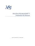
(4-1)
19
As you can see the environment with an oblong object which the sonar has a very hard
time reading because of its round shape is mapped fairly well considering its structure.
The four walls are defined in this map using medium filtering. Another important aspect
to this filtering is that it can tuned in many ways. The sensitivity of the sonar itself is
adjustable so that better readings of long flat objects can be taken accurately while
smaller objects are more likely missed. The opposite is true when the sensitivity is turned
up. Once the map has been attained the filter can be turned up or down in order to
optimize the map of the real world.
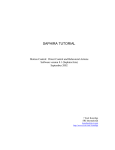
Our long hallway mapping test went very well whenever
we started our robot at the ideal perpendicular position
as shown below.
This test was taking over a 5 minutes time span down a
long hall found in the engineering dept. The walls were
constructed of drywall and as you can observe the walls
are very accurately mapped along with the doorways.
However this won’t be the case all the time when the
robot is placed in a random environment so also
duplicated this experiment with the robot at a biased
angle with a medium fitler.
(4-2)
However this won’t be the case all the time when the robot is placed in a random
environment so also duplicated this experiment with the robot at a biased angle with a
medium filter.
20
(4-3)
As you can see the smallest variation in angle can throw off the values somewhat. Our
results however turned out fairly decent as both the doorway and the walls were mapping
with decent precision.
Our last test was conducted in a random environment where no artificial biases could be
presented in favor of the sonar. The results are as follows:
(4-4)
(4-5)
With medium filtering the results we retrieved were very promising. Because of large
number of oblong objects and loose material, i.e. electrical wire found on the ground, we
were expecting very poor values. But in fact the robot was able to scan the garbage can
found on the left, which is the round half moon values taken on the left side of the wall.
21
Many of the loose wiring found at the end of the room was scanned fairly accurately and
the robot had no problems navigating through this environment.
22
CHAPTER 5 USER MANUAL
SOFTWARE INSTALLATION 1
Step 1:
Install Aria Active-Media Suite and Visual C++ on your computer.
Step 2:
In Visual C++, create a new MFC Application project titled “Mapping”
using the Wizard and the default settings.
Step 3:
Link the new project to the Aria libraries. (See Sample Aria projects for
information on how to link libraries)
Step 4:
Download myRobot.cpp and myRobot.h and import them into the project
workspace.
Step 5:
Replace MappingView.cpp and MappingView.h with the updated version.
Step 6:
Compile and Run the code.
QUICK INSTALLATION
Step 1:
Create a new Folder and copy the Mapping Directory into it
Step 2:
Install Aria Active-Media Suite and copy the libraries into the newly
created folder.
Step 3:
Open up the Mapping Workspace using Visual C++
Step 4:
Compile and Run the code.
23
CONNECTING AND DISCONNECTING FROM THE ROBOT:
You should automatically be connected to the robot upon execution of the program.
If by chance you are not, click on the Robot menu and select "Connect".
To disconnect from the robot simply close the program or select "Disconnect" from
the Robot menu.
CONTROLLING THE ROBOT:
up arrow - move forward
down arrow - move back
left arrow - rotate counter-clockwise 10 degrees
right arrow - rotate clockwise 10 degrees
enter - (Scan) sends the sonar data to the database
spacebar - draws a map using values from the database
delete - clears the data in the database and clears the screen
AUTOMATED FUNCTIONS:
Wander (double left-click) - Wanders around the room while scanning and avoiding
nearby objects and continually updating the map. Double left-click again to pause
and resume.
Spin and Scan (double right-click) - Rotates 360 degrees counter-clockwise while
taking scans every 10 degrees.
24
CHAPTER 6 Other Issues
1.Social
Social impact of our project would allow society to venture into hostile
environments which would be normally accessible for human interaction. For example
unsafe buildings could be probed by our robot for safe paths to travel. Hazmat teams
could be able to search buildings for obstacles and safe paths to traverse in order to find
precious cargo. Essentially it will allow society an artificial cognitive sense of mapping
as robots have allowed us to extend our senses without putting ourselves in immediate
harms way.
2.Political
Our project has no political aspect what so ever.
3.Economic
Our project replicated a costly piece of software that is sold by Activemedia and
could be easily further developed to be competitively held up against Activemedia’s
mapping software. In a sense we are on the road to stimulate the market for robotics
software.
4.Health
Our project has not direct relation to any current health issues.
5.Safety
Our project is relatively safe. The mapping software allows people to map
environments and get a better idea what their physical world looks like without them
getting out of their chair.
6.Manufacturability
The Mapping robot software can be easily ported to any amigobot making it very
accessible to anyone who owns both an amigobot and the activemedia software bundle.
25
Manufacturability is only limited to how many robots Activemedia produces per year and
different prices.
7.Sustainability
We developed the software to be very easily used and maintained. Documented
comments and simple user interface will give the user a better conceptual idea of how our
program works allowing the user to make new changes to the design if needed.
8.Environmental impact
Our product does not have an direct impact on the environment although it
important to note that most of the materials on our robot, except the power source, are
recyclable.
9.Usability
As noted the design of the robot interface was for simplicity and ease of use.
Basically all the user needs to do is push one button after uploading the code.
10.Lifelong Learning
The design on this robot could be developed in many other ways allowing those
who will take on this project in the future to learn even more about robotics and the way
we replicate our human senses to the artificial world. Multiple threading with other robots
and further development on ways to filter out sonar data are just a few more things we
could learn more about with further implementation.
11.Compassion
Our project, if developed further would be able to help the blind navigate through
environments without the use of a walking stick or walking dog. Our robot could actually
serve as a type of “seeing eye dog” that could be able to translate the maps into brail as
well.
26
CHAPTER 7 CONCLUSION
7.1. Summary of Work
After further testing the flaws of our code were worked out so that our final
working product is able to move, filter, and map. The movement algorithm proved to be
very reliable as our incident of impact to any obstacles in a room was minimized to zero
after we readjusted the turning algorithm. The filter is works well but needs to be
readjusted depending on what kind of environment the robot is mapping. The user will be
able to choose a best fit map by turning the filter up or down. The visual mapping part of
our project works well and maps the data values stored in our database straight to the user
with no problems.
7.2. Project Challenges and Future Implementation
Some of the challenges of our project included the limitations of sonar technology
as it doesn’t operate very well in certain environments especially that when the object to
be read is too far, too close, or too high of an angle. Obstacle avoidance was a challenge
to find the exact turn radius interval to allow the robot to not hit a blind spot found within
the sonar. Whenever the robot did make contact with a wall we usually experienced
wheel slippage as well which corrupted our sonar values. It is also important to note that
the velocity of forward movement and turning should be reasonably low as high
velocities would cause the robot to jerk when it moved causing more wheel slippage in
the process. Finding the correct threshold filter for our test environment was challenging
as well. Design aspects allow us to change this to suit what ever environment we may run
into decided upon the user.
Future implementation would include the ability to keep the sonar perpendicular
to the wall to provide us the best values possible from our sonar. As we analyzed earlier
we received the best readings whenever the sonar is perpendicular to an object. Dynamic
thresholding would be another aspect of future design as we hope the robot would be able
to determine the best degree of filtering by assessing the type of room it is in then
optimizing the filter to get the best fit map. Localization would also be ideally
implemented by fusing the odometer sensor along with the sonar to compare and contrast
27
the previous taken values with the current values to make a final determination that the
point it is at actually is the point in reality.
7.3. “The Big Picture”
Overall we would like to see this project continued and improved with years to
come. Hopefully even combine with other projects such as the formation robots. Further
development would allow further research into the optimization of sonar technology and
perhaps a better way to implement it in industry. We were fortunate enough to be able
have the accessibility to these great learning tools, the amigobots, and hope others in the
future will take full advantage of these robots in years to come.
28
Refrences
[1.] Autonomous Robot Vehicles. I.J. Cox and G.T. Wilfong, eds. Springer-Verlag, 1990.
Collection of papers on various issues in mobile robots.
[2.] Mobile Robot Self-Localization without Explicit Landmarks
R.G. Brown and B.R. Donald
http://www.cs.dartmout.edu/~brd/papers.html#Russel
[3.] Mobile Robot Localization and Map Building: A Multisensor Fusion Approach
J. Catellanos and J.Tardos. Boston, MA: Kluwer Academic Publishers, 2000.
[4.] Wall Following Using Angle Information Measured by a Single Ultrasonic
Transducer
Teruko Yata, Lindsay Kleeman, Shin’ichi Yuta.
http://www.ri.cmu.edu/pub_files/pub3/yata_teruko_1998_1/yata_teruko_1998_1.pdf
29
Appendix
Appendix A.1 MappingView.cpp:
// MappingView.cpp : implementation of the CMappingView class
//
#include
#include
#include
#include
#include
#include
#include
"stdafx.h"
"Mapping.h"
"MappingDoc.h"
"MappingView.h"
<math.h>
<process.h>
<windows.h>
#ifdef _DEBUG
#define new DEBUG_NEW
#undef THIS_FILE
static char THIS_FILE[] = __FILE__;
#endif
myRobot red;
/////////////////////////////////////////////////////////////////////////////
// CMappingView
IMPLEMENT_DYNCREATE(CMappingView, CView)
BEGIN_MESSAGE_MAP(CMappingView, CView)
//{{AFX_MSG_MAP(CMappingView)
ON_WM_LBUTTONDBLCLK()
ON_WM_RBUTTONDBLCLK()
ON_WM_KEYDOWN()
ON_WM_KEYUP()
30
ON_MESSAGE(WM_SCANDRAW, OnScanDraw)
ON_COMMAND(ID_ROBOT_CONNECT, OnRobotConnect)
ON_COMMAND(ID_ROBOT_DISCONNECT, OnRobotDisconnect)
//}}AFX_MSG_MAP
END_MESSAGE_MAP()
/////////////////////////////////////////////////////////////////////////////
// CMappingView construction/destruction
CMappingView::CMappingView()
{
red.connect();
filter = 0.0;
//minimum probability in order for coordinate to be valid (drawn)
mean = 800;
//mean for the gaussian function
stdev = 200;
//standard deviation for the gaussian function
PI = 3.14159265;
var = stdev*stdev;
xmax = 1020;
ymax = 675;
//width of the screen in pixels
//height of the screen in pixels
size = 2;
//size of the dot to be drawn at coordinate x,y
box = 12;
//increase the number to lower the resolution
xstart = xmax/2;
//x starting position of the robot on the screen (in this case, the center of the x
ystart = ymax/2;
//y starting position of the robot on the screen (in this case, the center of the y
axis)
axis)
xpos = xstart;
ypos = ystart;
moveThread=0;
//initialize at 0 to indicate no thread is running
//creates 3 brushes black, blue, and white
black = new CBrush();
31
black->CreateSolidBrush(RGB(0,0,0));
blue = new CBrush();
blue->CreateSolidBrush(RGB(0,0,255));
white = new CBrush();
white->CreateSolidBrush(RGB(255,255,255));
//creates a two-dimensional array of xmax and ymax
//and initializes the values to 0
DB = new double * [xmax];
for(int z=0; z<xmax; z++)
{
DB[z] = new double[ymax];
}
for(z=0; z<xmax; z++)
for(int b=0; b<ymax; b++)
DB[z][b]=0.0;
}
CMappingView::~CMappingView()
{
if(red.isConnected())
red.disconnect();
}
BOOL CMappingView::PreCreateWindow(CREATESTRUCT& cs)
{
return CView::PreCreateWindow(cs);
}
/////////////////////////////////////////////////////////////////////////////
// CMappingView drawing
void CMappingView::OnDraw(CDC* pDC)
{
CMappingDoc* pDoc = GetDocument();
ASSERT_VALID(pDoc);
draw();
}
32
/////////////////////////////////////////////////////////////////////////////
// CMappingView diagnostics
#ifdef _DEBUG
void CMappingView::AssertValid() const
{
CView::AssertValid();
}
void CMappingView::Dump(CDumpContext& dc) const
{
CView::Dump(dc);
}
CMappingDoc* CMappingView::GetDocument() // non-debug version is inline
{
ASSERT(m_pDocument->IsKindOf(RUNTIME_CLASS(CMappingDoc)));
return (CMappingDoc*)m_pDocument;
}
#endif //_DEBUG
/////////////////////////////////////////////////////////////////////////////
// CMappingView message handlers
//Thread consisting of the moving algorithm
UINT Move(LPVOID param)
{
bool left=true;
bool turn=false;
int i=0;
::PostMessage((HWND)param, WM_SCANDRAW, 0,0);
while(true)
{
while(red.checkFront())
{
if(left)
33
red.rotate(15);
else
red.rotate(-15);
::PostMessage((HWND)param, WM_SCANDRAW, 0,0);
turn=true;
}
red.move(10);
::PostMessage((HWND)param, WM_SCANDRAW, 0,0);
if(turn)
{
if(++i >= 10)
{
if(rand()%2==0)
left=true;
else
left=false;
i=0;
}
}
turn=false;
}
return 0;
}
void CMappingView::OnLButtonDblClk(UINT nFlags, CPoint point)
{
HWND hWnd = GetSafeHwnd();
if(moveThread==0)
{
pThread = AfxBeginThread(Move, hWnd, THREAD_PRIORITY_NORMAL);
moveThread=1;
//1 = thread running
}
else if(moveThread==2)
{
pThread->ResumeThread();
moveThread=1;
//1 = thread running
}
34
else
{
pThread->SuspendThread();
moveThread=2;
//2 = thread suspended
red.stop();
}
CView::OnLButtonDblClk(nFlags, point);
}
void CMappingView::OnRButtonDblClk(UINT nFlags, CPoint point)
{
scan();
draw();
for(int x=41; x>0; x--)
{
red.rotate(10);
while(!red.turnDone()) { }
scan();
draw();
}
CView::OnRButtonDblClk(nFlags, point);
}
void CMappingView::draw()
{
CClientDC dc(this);
dc.FillRect(CRect(xpos-size,ypos-size,xpos+size,ypos+size),white);
xpos
ypos
xpos
ypos
=
=
=
=
red.getX();
red.getY();
convertx(xpos);
converty(ypos);
dc.FillRect(CRect(xpos-size,ypos-size,xpos+size,ypos+size),black);
for(int x=0; x < xmax; x++)
{
35
for(int y=0; y < ymax; y++)
{
if(DB[x][y] > filter)
{
dc.FillRect(CRect(x-size,y-size,x+size,y+size),blue);
}
}
}
}
void CMappingView::dataB()
{
for(int x=0; x < 8 && sonars[x][0]!= 9999 && sonars[x][1]!=9999; x++)
{
int pointx = sonars[x][0];
int pointy = sonars[x][1];
int length = sonars[x][2];
double probability = Gauss(length);
pointx = convertx(pointx);
pointy = converty(pointy);
DB[pointx][pointy] += probability;
}
}
void CMappingView::Decrement(int x, int y)
{
DB[x][y]-=10;
}
void CMappingView::scan()
{
int xpos2 = red.getX();
int ypos2 = red.getY();
xpos2 = convertx(xpos);
ypos2 = converty(ypos);
Decrement(xpos2, ypos2);
sonars = red.scan();
dataB();
36
}
void CMappingView::OnKeyDown(UINT nChar, UINT nRepCnt, UINT nFlags)
{
switch(nChar)
{
//reset DB (delete)
case 46:
reset();
break;
//scan and draw (tab)
case 9:
scan();
draw();
break;
//draw (spacebar)
case 32:
draw();
break;
//scan (enter)
case 13:
scan();
break;
//move forward (up key)
case 38:
red.move(10);
//while(!red.moveDone()){ }
break;
//move backwards (down key)
case 40:
red.move(-10);
//while(!red.moveDone()){ }
break;
//rotate left (left key)
case 37:
red.rotate(10);
//while(!red.turnDone()) { }
break;
37
//rotate right (right key)
case 39:
red.rotate(-10);
//while(!red.turnDone()) { }
break;
}
CView::OnKeyDown(nChar, nRepCnt, nFlags);
}
void CMappingView::OnKeyUp(UINT nChar, UINT nRepCnt, UINT nFlags)
{
red.stop();
CView::OnKeyUp(nChar, nRepCnt, nFlags);
}
int CMappingView::convertx(int i)
{
i /= box;
i += xstart;
return i;
}
int CMappingView::converty(int i)
{
i /= -box;
i += ystart;
return i;
}
double CMappingView::Gauss(int x)
{
double A = 1/(stdev*sqrt(2*PI));
double B = ((x-mean)*(x-mean))/(2*var);
return 500*A*exp(-B);
}
38
void CMappingView::OnScanDraw(WPARAM wParam, LPARAM lParam)
{
scan();
draw();
}
void CMappingView::OnRobotConnect()
{
if(!red.isConnected())
red.connect();
}
void CMappingView::OnRobotDisconnect()
{
if(red.isConnected())
red.disconnect();
}
void CMappingView::reset()
{
for(int z=0; z<xmax; z++)
for(int b=0; b<ymax; b++)
DB[z][b]=0.0;
clearScreen();
}
void CMappingView::clearScreen()
{
CClientDC dc(this);
dc.FillRect(CRect(0,0,xmax,ymax),white);
}
39
Appendix A.2 MappingView.h:
// MappingView.h : interface of the CMappingView class
//
/////////////////////////////////////////////////////////////////////////////
#include "myRobot.h"
#if !defined(AFX_MAPPINGVIEW_H__92E42C4C_5421_11D7_9B52_00E0988A2243__INCLUDED_)
#define AFX_MAPPINGVIEW_H__92E42C4C_5421_11D7_9B52_00E0988A2243__INCLUDED_
#if _MSC_VER > 1000
#pragma once
#endif // _MSC_VER > 1000
const WM_SCANDRAW = WM_USER + 100;
class CMappingView : public CView
{
protected: // create from serialization only
CMappingView();
DECLARE_DYNCREATE(CMappingView);
double ** DB;
int xmax, ymax, xstart, ystart, size, xpos, ypos, box;
double ** sonars;
double mean, stdev, PI, var, filter;
CWinThread* pThread;
int moveThread;
CBrush * black, * blue, * white;
// Attributes
public:
CMappingDoc* GetDocument();
// Operations
public:
40
// Overrides
// ClassWizard generated virtual function overrides
//{{AFX_VIRTUAL(CMappingView)
public:
virtual void OnDraw(CDC* pDC); // overridden to draw this view
virtual BOOL PreCreateWindow(CREATESTRUCT& cs);
protected:
//}}AFX_VIRTUAL
// Implementation
public:
virtual ~CMappingView();
#ifdef _DEBUG
virtual void AssertValid() const;
virtual void Dump(CDumpContext& dc) const;
#endif
protected:
void scan();
position
void dataB();
void draw();
int convertx(int i);
int converty(int i);
double Gauss(int x);
void Decrement(int x, int y);
void reset();
void clearScreen();
//retrieves the position of the robot, decrements that
//in the database, and passes the sonar data to the database
//increments the coordinates of the database
//depending on the returned value from the gaussian function
//draws points depending on the values in the database
//converts the x value to be stored
//converts the y value to be stored
//returns a value between 0 and 1 depending on
//the values x, mean, and stdev
//decrements the value of the coordinates x,y
//sets all values in the database to 0
//clears the screen
// Generated message map functions
protected:
//{{AFX_MSG(CMappingView)
afx_msg void OnLButtonDblClk(UINT nFlags, CPoint point);
afx_msg void OnRButtonDblClk(UINT nFlags, CPoint point);
afx_msg void OnKeyDown(UINT nChar, UINT nRepCnt, UINT nFlags);
41
afx_msg
afx_msg
afx_msg
afx_msg
void
void
void
void
OnKeyUp(UINT nChar, UINT nRepCnt, UINT nFlags);
OnRobotConnect();
OnRobotDisconnect();
OnScanDraw(WPARAM wParam, LPARAM lParam);
//user-created message to execute
//scan and draw during a thread
//}}AFX_MSG
DECLARE_MESSAGE_MAP()
};
#ifndef _DEBUG // debug version in MappingView.cpp
inline CMappingDoc* CMappingView::GetDocument()
{ return (CMappingDoc*)m_pDocument; }
#endif
///////////////////////////////////////////////////////////////////////////////{{AFX_INSERT_LOCATION}}
// Microsoft Visual C++ will insert additional declarations immediately before the previous line.
#endif // !defined(AFX_MAPPINGVIEW_H__92E42C4C_5421_11D7_9B52_00E0988A2243__INCLUDED_)
42
Appendix A.3 MyRobot.cpp
// myRobot.cpp: implementation of the myRobot class.
//
//////////////////////////////////////////////////////////////////////
#include
#include
#include
#include
#include
"stdafx.h"
"Mapping.h"
"myRobot.h"
"Aria.h"
<fstream.h>
#ifdef _DEBUG
#undef THIS_FILE
static char THIS_FILE[]=__FILE__;
#define new DEBUG_NEW
#endif
//////////////////////////////////////////////////////////////////////
// Construction/Destruction
//////////////////////////////////////////////////////////////////////
ArRobot robot;
ArSerialConnection serConn;
ArSonarDevice sonar;
ArKeyHandler keyHandler;
double vel = 30;
double rotVel = 10;
int minDistance = 350;
myRobot::myRobot(){ }
myRobot::~myRobot(){}
void myRobot::move(int distance)
{
robot.setVel(vel);
robot.move(distance);
43
while(!robot.isMoveDone()){ }
}
void myRobot::rotate(int theta)
{
robot.setRotVel(rotVel);
robot.setDeltaHeading(theta);
while(!robot.isHeadingDone()){ }
}
double ** myRobot::scan(void)
{
int z, cursor=0;
int y = robot.getNumSonar();
double ** sonars = new double * [y];
for(z=0; z<y; z++)
{
sonars[z] = new double[3];
}
for(z=0; z<y; z++)
for(int b=0; b<3; b++)
sonars[z][b]=9999;
for(z=0; z<y ;z++)
{
//retrieves the position and angle of a specified sonar
double distance,theta;
int x,y;
switch(z)
{
case 0:
x=-105;
y=73;
theta=3.14159;
break;
case 1:
x=-78;
44
case
case
case
case
case
case
y=130;
theta=2.33874;
break;
2:
x=-30;
y=154;
theta=1.78024;
break;
3:
x=30;
y=154;
theta=1.36136;
break;
4:
x=78;
y=130;
theta=0.80285;
break;
5:
x=105;
y=73;
theta=0.00;
break;
6:
x=60;
y=-146;
theta=5.340708;
break;
7:
x=-60;
y=-146;
theta=4.084070;
break;
}
distance=robot.getSonarRange(z);
//adds sonar data only if the distance is between 300 and 1500
if(distance > 300 && distance < 1500)
45
{
theta = theta + robot.getTh() * 3.14159 / 180;
x=(-1* robot.getY()) + x + distance * cos(theta);
y=robot.getX() + y + distance * sin(theta);
sonars[cursor][0]=x;
sonars[cursor][1]=y;
sonars[cursor][2]=distance;
cursor++;
}
}
return sonars;
}
int myRobot::getX()
{
return -1 * robot.getY();
}
int myRobot::getY()
{
return robot.getX();
}
int myRobot::connect()
{
Aria::init();
Aria::setKeyHandler(&keyHandler);
robot.attachKeyHandler(&keyHandler);
serConn.setPort();
robot.setDeviceConnection(&serConn);
robot.addRangeDevice(&sonar);
if (!robot.blockingConnect())
{
printf("Could not connect to robot... exiting\n");
46
Aria::shutdown();
return 1;
}
// turn on the motors, turn off amigobot sounds
robot.comInt(ArCommands::ENABLE, 1);
robot.comInt(ArCommands::SOUNDTOG, 0);
robot.comInt(ArCommands::SONAR, 1);
// start the robot running, true so that if we lose connection the run stops
robot.runAsync(true);
return 0;
}
bool myRobot::turnDone(void)
{
return robot.isHeadingDone();
}
bool myRobot::moveDone(void)
{
return robot.isMoveDone();
}
void myRobot::stop(void)
{
robot.setVel(0);
robot.setRotVel(0);
}
bool myRobot::checkFront(void)
{
int range;
for(int x=0;x<=5;x++)
{
range = robot.getSonarRange(x);
if(range < minDistance)
47
return true;
}
return false;
}
int myRobot::disconnect(void)
{
robot.setVel(0);
Aria::shutdown();
robot.disconnect();
return 0;
}
bool myRobot::isConnected(void)
{
return robot.isConnected();
}
// Stop the robot
// Shutdown Aria
// Disconnect from the robot
//returns true if the robot is connected
:
48
Appendix A.4 MyRobot.h
// myRobot.h: interface for the myRobot class.
//
//////////////////////////////////////////////////////////////////////
#if !defined(AFX_MYROBOT_H__CB03EFE0_5F0F_11D7_9B52_00E0988A2243__INCLUDED_)
#define AFX_MYROBOT_H__CB03EFE0_5F0F_11D7_9B52_00E0988A2243__INCLUDED_
#if _MSC_VER > 1000
#pragma once
#endif // _MSC_VER > 1000
class myRobot
{
public:
myRobot();
virtual ~myRobot();
void move(int distance);
void rotate(int theta);
theta < 0
double ** scan(void);
//constructor
//deconstructor
//moves the robot forward if distance > 0 and backwards if distance < 0
//rotates the robot counter-clockwise for theta > 0 and clockwise for
//using the center of the robot as the relative position,
//returns and array of x,y coordinates of the detected object
//and the distance the sonar was from the object
int connect(void);
//connects to the robot
int disconnect(void);
//disconnects from the robot
bool turnDone(void);
//returns true if the robot is done turning
bool moveDone(void);
//returns true if the robot is done moving
void stop(void);
//Stops the robot from moving and turning
49
bool checkFront(void);
//returns true if there is something infront of the robot
int getX(void);
//returns the X-position of the robot where the front of the robot is
int getY(void);
//returns the y-position of the robot where the front of the robot is
bool isConnected(void);
//returns true if the robot is currently connected
north
north
};
#endif // !defined(AFX_MYROBOT_H__CB03EFE0_5F0F_11D7_9B52_00E0988A2243__INCLUDED_)
50