1
DV User's Manual
DV Version 1.27.41.00
Document Version 1.8
Confidential
Page 1
Contents
Revision History .............................................................................................................................. 4
1
2
Introduction .............................................................................................................................. 5
1.1
Supported CAN Interfaces................................................................................................ 5
1.2
Minimum System Requirements....................................................................................... 5
Layout ...................................................................................................................................... 5
2.1
Menus ............................................................................................................................... 5
2.2
Toolbars ............................................................................................................................ 6
2.2.1
Receive / Logging...................................................................................................... 6
2.2.2
Display Options ......................................................................................................... 6
2.2.3
Playback .................................................................................................................... 6
2.3
3
Status Bar ......................................................................................................................... 7
2.3.1
Receive Status Pane ................................................................................................. 7
2.3.2
Logging Status Panes ............................................................................................... 8
Settings .................................................................................................................................... 8
3.1
Log File Options................................................................................................................ 8
3.1.1
Log Filename & Location........................................................................................... 8
3.1.2
Log File Maximum Duration ...................................................................................... 9
3.2
CAN Bus ........................................................................................................................... 9
3.2.1
Channel Usage.......................................................................................................... 9
3.2.2
Bus Parameters......................................................................................................... 9
3.3
Video................................................................................................................................. 9
3.3.1
3.3.1.1
ImperX & ImperX Pro cards ............................................................................... 9
3.3.1.2
Web Cam ......................................................................................................... 10
3.3.2
4
5
Main Video Settings................................................................................................... 9
Auxiliary Video Settings........................................................................................... 11
Manual Logging (This section not implemented) ................................................................... 12
4.1
Continuous Logging (This section not implemented) ..................................................... 12
4.2
Triggered Logging (This section not implemented) ........................................................ 12
Automatic Logging (CAN Trigger).......................................................................................... 12
5.1
Enable / Disable.............................................................................................................. 13
5.2
Auto-Logging Modes....................................................................................................... 13
5.3
CAN Trigger Definition File ............................................................................................. 14
5.3.1.1
Format .............................................................................................................. 14
5.3.1.2
File Parse Errors .............................................................................................. 17
6
Remote Control...................................................................................................................... 18
7
Command Line Options ......................................................................................................... 18
8
Data Replay ........................................................................................................................... 18
Confidential
Page 2
8.1
9
Main Video Display ......................................................................................................... 18
8.1.1
Creating Video Clips with Overlay........................................................................... 18
8.1.2
Saving Single Images with Overlay......................................................................... 19
Error Reporting (This section not implemented) .................................................................... 19
Tables
Table I. Supported CAN Interfaces ................................................................................................ 5
Table II. Log Filename Auto-Expand Keystrings............................................................................ 8
Table III. Description of Autonomous Logging Modes ................................................................. 13
Table IV. Errors detected in CAN trigger configuration files. ....................................................... 17
Table V. Limits imposed on Signal and Trigger definitions.......................................................... 17
Table VI. Command Line Options. ............................................................................................... 18
Figures
Figure 1. Main Menu ...................................................................................................................... 6
Figure 2. Receive/Logging Toolbar ................................................................................................ 6
Figure 3. Display Options............................................................................................................... 6
Figure 4. Replay Toolbar................................................................................................................ 7
Figure 5. Main Status Bar .............................................................................................................. 7
Figure 6. Log Options Dialog ......................................................................................................... 8
Figure 7. Main Video Settings ...................................................................................................... 10
Figure 8. Web Cam Settings Dialog............................................................................................. 11
Figure 9. Auxiliary Video Settings ................................................................................................ 12
Figure 10. Sample CAN Trigger Definition File............................................................................ 15
Confidential
Page 3
Revision History
Doc
Version
DV Version
Date
Author
Changes
1.0
1.15.39.09
20060922
LRH
Initial revision, contains only documentation for CAN Trigger
function.
1.1
1.15.39.10
20060929
LRH
Max number of CAN triggers has been increased to 45. Clarified
definition of signal mask and trigger compare value.
1.2
1.16.40.06
20061031
LRH
Modified description of the Status Bar and Display Options Toolbar
to match new implementation. Updated toolbar and menu
descriptions. Began migrating general DV settings and use info
from PowerPoint Help file.
1.3
1.19.01.03
20070712
RPA
Began Data Replay section by migrating information into Record to
Video and Record to Image sections from PowerPoint Help file.
1.4
1.23.01.00
20080115
LRH
Add CAN bus config.
20080212
LRH
Add mention of XCP in status bar display
1.5
1.6
1.24.19.00
20080807
LRH
Modify CAN trigger file format specification. Signals now include
scale factor and offset values. Trigger conditions are specified in
engineering units.
1.7
1.26.25.00
20090320
SM
Added Video section including web cam usage for logging
1.8
1.27.41.00
20091123
SM
Updated web cam section to include the support of two different
image sizes: 320x240 and 640x480.
Confidential
Page 4
1 Introduction
1.1
Supported CAN Interfaces
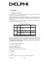
DV will automatically search for supported CAN cards on the host computer. Detected cards will
be selected in the order indicated in the table below.
Each interface requires that the CAN hardware and drivers be correctly installed. For each
supported card, the dll indicated in the table is supplied with DV, and must be located in the
directory containing the DV executable (or in the library search path, which usually includes
winnt\system32).
For best performance under high busload situations, Vector hardware is recommended. See
Section 3.2 for info on CAN bus configuration in DV.
Table I. Supported CAN Interfaces
Brand
Search
Order
Vector
1
Supported Cards
CANCard-X
Required
Library
vcand32.dll
CANCard-XL
CANCase-XL (USB)
Softing
2
CANAC104 card (PC104)
canac104.dll
3
CANcard-2
cancard.dll
CANcard-SJA
Kvaser
4
CANLap (PCMCIA and USB)
canlib32.dll
If more than two CAN channels are to be used simultaneously, then Vector hardware must be
used, and the driver must be configured for Software time synchronization. Use the Vector
Hardware tool in the Control Panel to set the synchronization method (use the tool to set General
Information/Settings/Synchronize Hardware = YES). Hardware time-base synchronization and
use of SyncBox and sync line not supported.
1.2
Minimum System Requirements
Processor Speed: 1.6GHz or higher
RAM Memory: 512MB or higher
Operating system: Windows 2000 or XP
Hard Disk: 1Gbyte free and relatively un-fragmented
2 Layout
2.1
Menus
DV's main menu appears in the upper left corner of the main display window.
Confidential
Page 5
Change video source
and logging settings
Open log files
for Replay
Enable/Disable the View of
optional windows associated
with the Display Format
Version-Specific
Menus
Get Program
Version Info
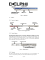
Figure 1. Main Menu
2.2
Toolbars
2.2.1 Receive / Logging
Receive Data
On/Off
Start/Stop Manual
Logging
Set Logfile Basename
Start Triggered
Logging
Enable/Disable
Autonomous Mode
Enable/Disable Automatic
CAN-Triggered Logging Mode
Figure 2. Receive/Logging Toolbar
2.2.2 Display Options
The display options toolbar controls how raw data is interpreted and displayed in both the
Receive/Logging and Playback modes. The left-most drop-down box contains a list of the
available Data Format interpretations (the sensor ACC3 is selected in the example below). The
second box contains a list of the Display Formats or Views available for the selected Data
Format. The remaining controls on this toolbar are specific to each particular Data/Display
Format combination, and are documented elsewhere.
Select Data Format
Select Display Format
Toggle Display-Specific Options
(Button Labels & Functions May Vary By Display)
Figure 3. Display Options
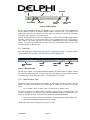
2.2.3 Playback
This toolbar is visible only when a file is open for playback (e.g., the result of File/Open). The
controls are self-explanatory, allowing one to move forward and back through the open file.
Confidential
Page 6
Toggle Play/Stop
Step Forward
Enter Index
Slide Forward/Back
Step Back
Jump Back
to Index
Jump Forward
to Index
Figure 4. Replay Toolbar
For the Step Forward/Back buttons, the definition of one "step" depends on the Data/Display
Format selections made on the Display Options toolbar (Section 2.2.2). For example, for a
single radar sensor one step might be one scan, while for a multi-sensor system one step might
move to the end of the next scan of either sensor.
All data collected with DV has some associated Index – either a native quantity supplied by the
observed system (such as a scan or frame index), or one assigned by DV (such as a message or
cycle counter). The nature and source of this index is dependent on the selected Data/Display
Format. To account for possible rollovers in the Index, the "Jump" buttons allow one to search
for a desired index in either direction.
2.3
Status Bar
DV's main Status Bar is located at the bottom of the main program window. It contains separate
regions for Help, Receive Status, and CAN, Video and XCP Logging Status.
Context Sensitive
Help
Receive
Status
CAN Logging
Status
Video Logging
Status
Figure 5. Main Status Bar
The help pane displays concise help information about the DV control (menu or toolbar element)
the mouse is currently pointed at. Contrary to the text in the display, pressing F1 will not produce
useful help. The content of the other panes is described in the next sections.
2.3.1 Receive Status Pane
The Receive Status Pane shows current statistics for CAN, Video and XCP receiving. The line
below is a sample of the Receive status information for CAN plus one Video and one XCP
source:
15 C: 1282m/s 63.3s V: 10.0f/s 49.8s V2: 0.0f/s 0.0s X: 40.0m/s 38.4s
The left-most element is a running counter of updates of this pane since receiving began. This
counter is followed by four data blocks that provide information about the receipt of CAN (C:),
Video (V:) and XCP (X:) data. Each data block contains the following information:
Data rate (messages or frames) received per second (including any "generated" by DV)
Data amount currently held in the queue (in seconds)
The Receive Status Pane is updated once every 4 seconds.
Confidential
Page 7
2.3.2 Logging Status Panes
Three Logging Status Panes show current statistics for CAN, Video and XCP logging. The
example below is a snapshot of CAN (C:) logging information (video (V:) and XCP (X:)
information is similar):
C: 104235 16
The two numbers in each CAN or Video block describe:
The total number of messages or frames logged (written to file)
The number of messages or frames remaining to be written (to catch up to receive)
The Logging Status Pane is updated once every 4 seconds.
While logging (systems with a constant average data rate), the number of messages/frames
remaining will be constant or decreasing if the logging task is able to keep up with the receive
task. If this number is increasing, the logging may eventually fall so far behind that new data will
overwrite old data before it is written to the log file.
3 Settings
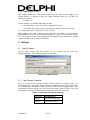
3.1
Log File Options
Log file name, location, and max duration can be selected with the menu item
Settings/Log/Options. The resulting dialog box is shown below.
Figure 6. Log Options Dialog
3.1.1 Log Filename & Location
The user specifies the base filename and the directory where logs should be stored. DV
automatically creates log filenames by appending a three-digit integer to the specified base name
(e.g., mylog005.dvl). This integer increases by one for each new log file (logging event). If the
specified base filename includes any of the special key strings shown in Table II, these will
automatically be expanded to their respective quantities when the files are created.
Table II. Log Filename Auto-Expand Keystrings
Confidential
Key string
Auto-Expands to
%Date%
Current date: yyyymmdd
%Time%
Current time: hhmmss
Page 8
3.1.2 Log File Maximum Duration
The default maximum log file duration is 360 seconds (6 minutes). Once the log time has
exceeded the specified duration, the current log file is closed and a new log file with incremented
number is automatically started. Data during this transition period (1-2 seconds) are not logged.
3.2
CAN Bus
CAN bus options may be configured with the dialog reached via menu item Settings/CAN Bus.
Currently, only the number of CAN channels to use can be selected. Verification and
configuration of the channels is not performed until Receiving is started. See Section 1.1 for a list
of supported hardware.
3.2.1 Channel Usage
Two or four channels may be selected for use. For PCMCIA card channels, a transceiver must
be connected before channel initialization (on Receive), or the channel will not be activated.
3.2.2 Bus Parameters
CAN channel settings such as bus bit rate are currently hard-coded and not configurable. The bit
rate on all configured channels is set to 500Kbps.
3.3
Video
DV can log video data up to two video sources simultaneously: one is called the Main video, the
other Auxiliary video. The Main video is used as the primary video data, while the Auxiliary video
is used for a second camera for ground truthing purposes.
The video data is stored in AVI files. The data from the Main video source is written to AVI files
with the following naming convention: “dvl_basename.avi”. Data from the Auxiliary video source
is written to AVI files with “dvl_basename_v2.avi” naming convention.
To enable video logging, select the menu item Settings / Video Capture / Enable to enable video
logging. Then select the menu Settings / Video Capture / Options to see available video sources
for the Main and Auxiliary Video. Error! Reference source not found. and Figure 9 show the
Main and Auxiliary video settings dialog boxes, respectively.
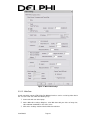
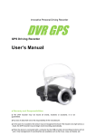
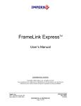
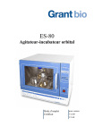
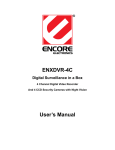
3.3.1 Main Video Settings
The Main Video Settings dialog box shown in Error! Reference source not found. is typically
used to configure primary video logging interface. Some video sources are used specifically for
customer specific programs, while others may be used for general video logging purposes.
On the dialog box, first the user selects the type of video source. Sub-options such as available
video compressors (Codec) and frame rate vary depending of the video source selected.
For general video data logging purposes (e.g. to capture the driving scene), the user may select
one of the following video sources: ImperX, ImperX Pro and Web Cam.
3.3.1.1 ImperX & ImperX Pro cards
There are three codec options available for these cards (uncompressed, Indeo and JpegLS). The
user selects Quality for Indeo or Loss Level for JpegLS codec. In addition, the users must select
the maximum logging frame rate. The recommended frame rate is 5 fps for ImperX card and 10
fps for the newer more efficient ImperX Pro card.
Confidential
Page 9
Figure 7. Main Video Settings
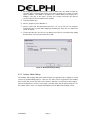
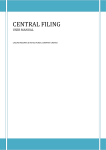
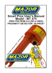
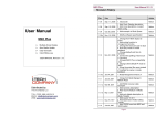
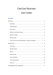
3.3.1.2 Web Cam
A web cam which supports VFW (Video For Window) interfaces can be used to log video data in
DV. To use the web cam, follow the following steps:
1. Connect the web cam to the laptop
2. On the Main video settings dialog box, select Web Cam with your choice of image size,
either 320x240 or 640x480, as the video source.
3. Click on the "Settings" button under the Web Cam radio box.
Confidential
Page 10
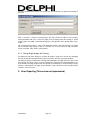
4. On the popup dialog box (should be the same or similar to the one shown in Figure 8),
select the image resolution that matches your choice of image size. If there are codec
options available, select RGB or uncompressed. If neither RGB nor uncompressed is
available, select any of the codecs (a faster one is better) and make sure that the
selected codec has been installed on the machine.
5. Leave the Number to 0.
6. Select a JpegLS loss level. Default is 3.
7. Choose a frame rate. Recommended frame rate is 10 – 15 fps. The user can verify the
actual frame rate received during logging by watching DV status bar (see Status Bar
section for details).
8. To lower the video file size, the user can either increase the loss level (the image quality
become lower) or decrease the frame rate or both.
Figure 8. Web Cam Settings Dialog
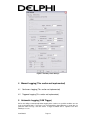
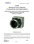
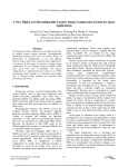
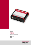
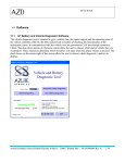
3.3.2 Auxiliary Video Settings
The Auxiliary Video Settings dialog box shown in Figure 9 is typically used to configure a second
camera for ground truthing purposes. There are less video sources supported for the Auxiliary
video. Select “Not used” as the video source if there is data from a second camera to be logged.
ImperX and ImperX Pro can be used to log the secondary video data for general purposes. For
the settings of these cards, see ImperX and PmperX Pro in the Main Video Settings section.
Confidential
Page 11
Figure 9. Auxiliary Video Settings
4 Manual Logging (This section not implemented)
4.1
Continuous Logging (This section not implemented)
4.2
Triggered Logging (This section not implemented)
5 Automatic Logging (CAN Trigger)
DV has the ability to automatically initiate logging when certain user-specified conditions are met
in the received CAN data. For instance, one could identify the Signal Warning as certain bits of a
particular CAN message, and then define a trigger Condition that is signaled each time
Warning=1 occurs.
Confidential
Page 12
The current implementation initiates a fixed-length triggered log every time a defined trigger
condition transitions from false to true.
5.1
Enable / Disable
Status of the Automatic Logging feature is reported by the CANTrigger checkbox on the
Receive/Logging Toolbar (Section 1). This function is available only if DV is launched with the
command line option /t. In addition, a specially formatted trigger configuration file (see Section
5.2) is required to define the CAN Signals and Trigger Conditions for the function. This file must
be in the directory with the DV executable. Upon launch, DV will parse the configuration file, and
construct a CAN Signal and Trigger Condition database. If no errors are detected, then Autologging will be made available (CANTrigger checkbox will be un-grayed) and the function will
immediately be active/enabled (checkbox checked).
Not Available
Available, Enabled
Available, Disabled
When available, operation of the Automatic Logging feature can be enabled or disabled by the
user. Disabling the feature will cause DV to ignore all trigger conditions and prevent autologging. This setting is not remembered from one launch to the next (use of the /t switch always
enables auto-logging). When logging is not desired, the function must be manually disabled or
receiving stopped.
5.2
Auto-Logging Modes
DV is intended to support the Auto-logging modes shown in Table III. Each of these modes is
controlled by one of the following Trigger Objects:
CAN Message Receipt – Monitors receipt of CAN messages with specified CAN Id and
channel. Does not monitor data in the CAN message except possibly to determine that
the correct message has been received (e.g., particular value in first data byte might
signal the first of a sequence of same-Id messages).
CAN Trigger Condition – A trigger Condition is defined as a list of one or more Primitives,
each of which performs a single logical comparison on a defined Signal on the CAN bus.
For example, a primitive might represent the comparison Speed > 30, or Warning = 1.
The trigger Condition is set or true only when all of its primitives evaluate to true (e.g.,
TrigCondition = Primitive1 AND Primitive2 AND… PrimitiveN).
Table III. Description of Autonomous Logging Modes
Mode
Trigger
Object
Log Type
Description
ID
CAN
Message
Receipt
Fixed-length
(pre+post
trigger seconds) Triggered
Log
EDGE
CAN Trigger
Condition
LEVEL
CAN Trigger
Condition
Fixed-length
(pre+post
trigger seconds) triggered
log
Variable-length Continuous
Log
Initiate a log when a particular CAN
Message is received. The data in the
message is not consulted. (not yet /
no longer implemented)
Initiate a log when the Condition
transitions from false to true.
Confidential
Page 13
Initiate a continuous log when
Condition becomes true. Continues
logging while Condition remains true.
(not yet implemented)
The current system implements only the EDGE mode, designed to trigger on the rising edge of a
Trigger Condition. It triggers when the Condition becomes true, and cannot re-trigger until the
Condition becomes true again (necessarily becoming false in-between).
The various modes produce one of two types of logs:
Fixed-length Triggered Log – Log collected as if the user pressed the Trig button on the
Receive/Logging toolbar. The length of the log is pre+post trigger seconds (see Section
4.2 for details).
Variable-length Continuous Log – Log collected as if the user pressed the Log button on
the Receive/Logging toolbar. The log begins at the time of the event (no pre-trigger), and
continues until the trigger Condition is no longer satisfied.
In all modes,the system will mark the location in the data where the trigger occurred. [It would be
nice if the (name of?) the Condition that triggered the log was also recorded, but this is not yet
implemented.]
5.3
CAN Trigger Definition File
The CAN trigger definition file contains the specification of CAN Signals in a way similar to how
one might define a Signal in a Canalyzer Database (e.g. which message ID, which bits, etc.).
The file also allows the specification of conditions or tests on these Signals that will trigger
logging.
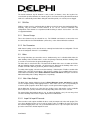
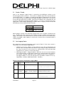
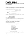
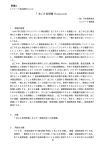
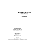
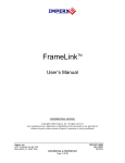
5.3.1.1 Format
The CAN trigger definition file is a text file consisting of three parts: the Version Identification
Block, the Signal Definition Block, and the Trigger Condition Definition Block. These blocks must
appear in the order listed. The beginning of each block is marked by a line containing a specific
key string, and followed by subsequent lines that contain the signal or trigger definitions. The key
string and format of each block are described in the following paragraphs, in which the sample
definition file shown in Figure 10 is used as an example.
Any line beginning with a pound sign (#) denotes a comment. The parser ignores both comment
and blank lines. All key strings and names (e.g., signal and trigger names) are case-sensitive.
Detected file errors are described in Section 5.3.1.2.
#DV_CAN_TRIGGER V1.1
#
# Configuration: Sample Project X
# Version: 2.1
# Author: Lisa Hamilton
# Date: 21 Sept 2006
# Source: Project X Canalyzer Database V4.5 (projX.dbc)
CAN_SIG_DEF
# SIGNAL_NAME = CH, ID, START, SIZE, MASK, SIGN, FACTOR, OFFSET
Warning = 2,074,3,1,10,U,1,0
#
true speed = signal/16 m/s
Speed
= 1,600,0,2,ffff,U,0.0625,0.0
#
true yaw rate = signal/16 d/sg
Yawrate = 1,600,2,2,ffff,S,0.0625,0.0
Scan
= 1,601,0,2,ffff,U,1,0
ScanLow = 1,601,0,2,1fff,U,1,0
CAN_TRG_ENA
Confidential
Page 14
# TRIG_NAME = SIGNAL, LOGIC, VALUE; SIGNAL, LOGIC, VALUE; ...
#
30 m/s
HighSpeedWarn
= Speed,GE,30.0; Warning,EQ,1
LowSpeedWarn
= Speed,LT,30.0; Warning,EQ,1
Every6Min
= ScanLow,EQ,4096
#
5 d/s
HighYawRight
= Yawrate,GT,5.0
HighYawLeft
= Yawrate,LT,-5.0
Figure 10. Sample CAN Trigger Definition File.
5.3.1.1.1 Version Identification
The first line of the configuration file must contain the specific Version Identification Key String
that tells DV how to interpret the rest of the file.
The current version string is:
#DV_CAN_TRIGGER V1.1. Comments should be used in this block to provide custom version,
date, author, and source information.
5.3.1.1.2 CAN Signal Definition
The CAN Signal Definition Block defines the CAN signals that DV will extract and monitor. Its
beginning is denoted by a line containing the key string CAN_SIG_DEF. Subsequent lines
provide the signal definitions, one per line.
Each signal is described by a unique name followed by a series of comma-separated descriptors
as follows:
SIGNAL_NAME = CH, ID, START, SIZE, MASK, SIGN, FACTOR, OFFSET
A description of the parameters used to define the signal is presented below:
SIGNAL_NAME: Unique, descriptive name of CAN signal
CH: CAN channel to monitor, “CH1” or “CH2” (range: 1, 2).
ID: CAN message ID containing the desired signal, written as a 3-digit
hexadecimal value (range: 0-7ff)
START: Byte offset to the byte containing the msb of the signal in the message
(range: 0-7). Note that the byte numbering begins with 0 to match that used
in the Message Layout view in Canalyzer.
SIZE: Size of the signal in bytes (range: 1-4). Single-bit boolean flags shall use a
size of ‘1’ byte with the unused bits masked off using the MASK parameter.
MASK: Hexadecimal value used to mask ‘don’t care’ bits from the defined signal.
The signal will be created by AND'ing this mask with the selected signal
bytes and then shifting the result so that the least significant bit of the signal
corresponds to the least significant high-bit in the mask. To use entire byte,
set mask to "FF" for a 1-byte value, "FFFF" for a 2-byte value, etc. A mask
of "A0" will result in a 3-bit signal created from the three high bits of the byte
(but the value of the middle bit will be ignored, or treated as zero, when
computing the signal value).
SIGN: Signal value should be treated as signed (S) or unsigned (U).
FACTOR: Multiplier used to compute actual signal value from CAN message bits(s).
Equivalent to Vector CANdb++ Editor definition of signal FACTOR.
OFFSET: Constant offset applied after scale FACTOR to compute actual signal value.
Equivalent to Vector CANdb++ Editor definition of signal OFFSET.
BYTE_ORDER: Byte order (not yet implemented). Only Motorola is currently supported.
Confidential
Page 15
Comments should be used in this block to clarify the meaning or units of signals and to note other
useful information such as scale factors. See Table V for limits imposed on the number of
Messages and Signals defined.
Examples
EX #1: Define the single-bit warning signal as bit 4 of the fourth byte of CAN message 0x074,
channel 2.
Warning = 2,074,3,1,10,U,1,0
EX #2: Define Speed as the first two bytes of CAN message 0x600 on channel 1.
#
Speed
true speed = byte_value/16 m/s
= 1,600,0,2,ffff,U,0.0625,0.0
EX #3: Define the signed16-bit Yawrate as the third and fourth bytes of CAN message 0x600 on
channel 1.
#
Yawrate
true yaw rate = byte_value/16 d/s
= 1,600,2,2,ffff,S,0.0625,0.0
EX #4: Define Scan as the first two bytes of CAN message 0x601 on channel 1. Also define
ScanLow as the lower 13 bits of the same quantity.
Scan
= 1,601,0,2,ffff,U,1,0
ScanLow
= 1,601,0,2,1fff,U,1,0
5.3.1.1.3 CAN Trigger Condition Definition
The CAN Trigger Condition Block begins with the key string CAN_TRIG_ENA and defines the
trigger conditions that DV will monitor. Following the key string line are trigger conditions, one
per line.
Each trigger condition is defined according to the following syntax that specifies one or more
primitives separated by semicolons:
TRIGGER_NAME = SIGNAL, LOGIC, VALUE; SIGNAL, LOGIC, VALUE; ...
The trigger condition descriptives are as follows:
TRIGGER_NAME: Unique, descriptive name of CAN trigger condition
SIGNAL: Name of signal defined in Signal Definition Block
LOGIC: Name of logical test to perform. The valid tests are:
EQ : Equal to VALUE
NE : Not equal to VALUE
LT : Less than VALUE
LE : Less than or equal to VALUE
GT : Greater than VALUE
GE : Greater than or equal to VALUE
VALUE: Comparison value defining scaled signal value (expressed in engineering
units, e.g. m/s) that will initiate trigger.
Comments can be used in this block to clarify the meaning of triggers and to note other useful
info such as scale factors. See Table V for limits imposed on the number of Primitives and
Triggers defined and on the number of Primitive defined for a single Signal.
Confidential
Page 16
Examples
EX #1: Trigger when a warning is issued (Warning bit set to 1) and the Speed >= 30m/s. Speed
comparison value includes scale factor of 128 needed to compensate for un-scaled signal.
#
30 m/s
HighSpeedWarn
= Speed, GE, 30.0; Warning, EQ, 1
EX #2: Trigger when a warning is issued (Warning bit set to 1) and the Speed < 30m/s.
#
30 m/s
LowSpeedWarn = Speed, LT, 30.0; Warning, EQ, 1
EX #3: Trigger every six minutes (6.8 minutes measured using low bits of a 100ms counter
present in CAN data).
Every6Min
= ScanLow, EQ, 4096
EX #4: Trigger when yaw rate exceeds 5 degrees/sec.
#
5 d/s
HighYawRight = Yawrate, GT, 5
HighYawLeft
= Yawrate, LT, -5
5.3.1.2 File Parse Errors
DV cannot validate the data in the trigger configuration file, but the parser can detect the various
syntactical and file errors shown in Table IV. Additionally, certain limits are imposed on how
many Messages, Signals, and Triggers are defined and used (see Table V). All error details
(including line number, where applicable) are reported to the user via DV's regular error reporting
methods (see Section 9, Error Reporting).
Table IV. Errors detected in CAN trigger configuration files.
Error Text
Subtext
Cannot open trigger specification file <filename>.
Error in Signal specification on line <#> of <filename>.
{Subtext}
Signal skipped.
Error in Trigger specification on line <#> of <filename>.
{Subtext}
Trigger Skipped.
Incorrect
sign
specification
<string>.
Incorrect number of valid tokens
found <# found>.
Cannot find trigger name.
Incorrect number of valid tokens
found <# found>.
Invalid relation specification
<string>.
{Message/Signal/Trigger Limit Errors, see Table V}
Multiple Signals defined with the name <name>.
Trigger condition <name> refers to undefined Signal
<name>.
Failed post-processing of trigger data in file <filename>.
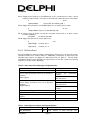
Table V. Limits imposed on Signal and Trigger definitions.
Quantity
Limit
Limit Description
MAX_MESSAGES
20
Total
Confidential
Page 17
number
of
CAN
message
ID's
MAX_SIGNALS_PER_MESSAGE
20
MAX_PRIMITIVES_PER_SIGNAL
20
MAX_PRIMITIVES_PER_TRIGGER
MAX_TRIGGERS
5
45
referenced.
Number of signals defined for one message.
Number of primitives that depend on each
Signal.
Number of primitives allowed per trigger.
Total number of triggers defined.
6 Remote Control
DV allows trigger and some other requests to be input remotely. Currently, one must have a
particular piece of hardware installed in the data-logging machine (usually a PiP computer) for
this function. In the future, a switch/LED circuit connected to the logging laptop parallel port will
do. Remote operations include start/stop manual logging, enable/disable CAN triggered logging,
request triggered log, etc. System pulse and other diagnostic signals can be displayed to the
driver via LED.
7 Command Line Options
The supported command line options are shown in Table VI. These can be used on the
command line of a DOS shell window, or they can be specified in the Properties page of a
shortcut to DV.
Option
Description
/r
Start receiving immediately on launch.
/l
Start logging immediately on launch. (Use with /r)
/t
Enable Automatic Logging (CANTrigger) mode. (See Section 5)
*.dvl
Open the specified log file on launch.
/snnn
Automatically jump forward to the first instance of the index
specified by "nnnn". Must be used with the filename option
above. (Note, there is no "space" between the /s characters and
the index number).
Replay
Receive /
Logging
Table VI. Command Line Options.
8 Data Replay
8.1
Main Video Display
8.1.1 Creating Video Clips with Overlay
Recording the main video display to a video will output a selection of both the underlying video
file and the DV-generated overlay. This output will be a separate video file that can be viewed in
any media player, without the need for DV.
Recording a video is initiated by selecting Record Main Video Display/Start in the right-click menu
of the main video display. Filename, target directory, and watermark can be selected. The “.avi”
Confidential
Page 18
must be included at the end of the chosen file name; the watermark is an optional text overlay of
the video.
After an encoder is selected, recording begins. Any frame viewed is added to the recording;
moving backwards will cause a reversal of action in the recording, rather than change its overall
stopping point. Recording is terminated through the same right-click menu through which it was
begun.
The recommended encoder is “x.264” used with default settings, which will generate a recording
with reasonable image quality as well as small file size. It can be found on http://www.freecodecs.com/x264_Video_Codec_download.htm.
8.1.2 Saving Single Images with Overlay
Recording the main video display to a picture will output a single frame of both the underlying
video file and the DV-generated overlay, which can then be opened in any image program.
Recording and image is initiated by selecting Output Window in the right-click menu of the main
video display. The image can be saved as a bitmap file or exported to the clipboard, where it can
be pasted into any image program and subsequently saved. If bitmap is selected, filename, target
directory, and watermark can again be specified; the “.bmp” extension must be included at the
end of the chosen file name.
9 Error Reporting (This section not implemented)
Confidential
Page 19
Index (This section not implemented)
Error! No index entries found.
Confidential
Page 20