1
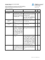
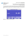
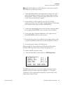
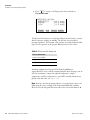
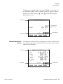
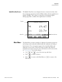
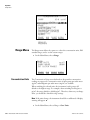
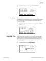
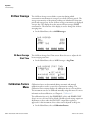
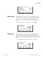
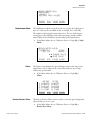
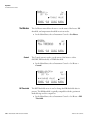
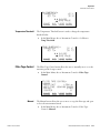
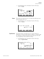
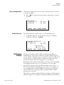
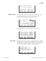
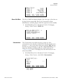
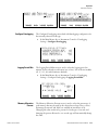
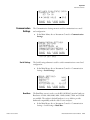
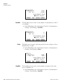
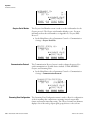
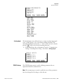
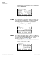
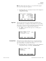
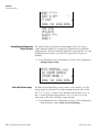
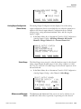
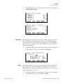
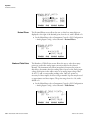
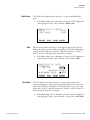
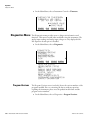
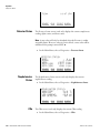
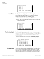
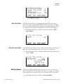
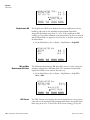
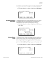
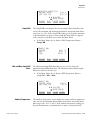
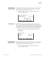
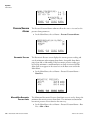
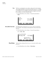
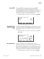
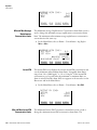
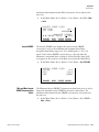
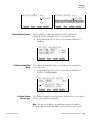
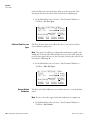
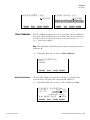
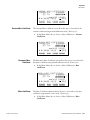
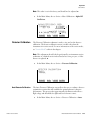
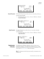
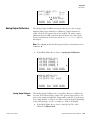
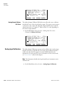
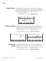
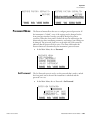
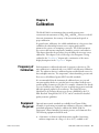
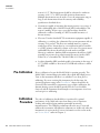
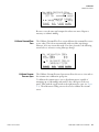
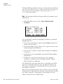
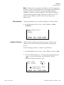
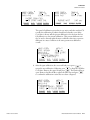
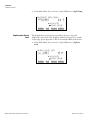
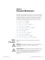
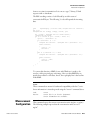
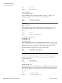
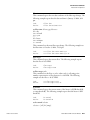
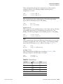
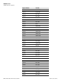
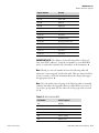
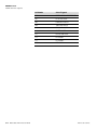
Operation
Volumetric Conditions
Note The digital outputs may take up to one second after the assigned
state occurs to show up on the outputs. ▲
●
In the Main Menu, choose Instrument Controls > I/O Configuration
> Output Relay Settings.
OUTPUT RELAY SETTINGS:
>1
NOP
CONC ALARM
2
NOP
LOCAL/REMOTE
3
NOP
UNITS
4
NOP
GEN ALARM
5
NOP
NONE ª
RANGE
Logic State
AVG
DIAGS ALARM
The Logic State menu item is used to change the selected I/O relay to
either normally open or normally closed. The default state is open, which
indicates that a relay connected between the digital output pin and ground
is normally open and closes to trigger the digital output action.
●
Press
to toggle and set the logic state to normally open or
normally closed.
OUTPUT RELAY SETUP:
>LOGIC STATE
INSTRUMENT STATE
RANGE
Instrument State
AVG
OPEN
DIAGS ALARM
The Instrument State submenu allows the user to select the instrument
state that is assigned to the selected relay output. A submenu lists signal
types of either alarms or non-alarm to choose from.
●
In the Main Menu, choose Instrument Controls > I/O Configuration
> Output Relay Settings > select Relay > Instrument State.
CHOOSE SIGNAL TYPE:
>ALARMS
NON-ALARM
RANGE
Thermo Fisher Scientific
AVG
DIAGS ALARM
Model 5030i SHARP Instruction Manual
3-45