1
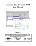
WASP Builder
User Manual -- Version 1.2
Developed by the Integrated Decision Support Group (IDS) for
the United States Bureau of Reclamation
and the Environmental Protection Agency (EPA).
U.S.
Environmental
Protection
Agency
WASP Builder User Manual, Version 1.2
Copyright
Copyright © 2000 Integrated Decision Support Group
601 South Howes, USC Suite 502
Colorado State University
Fort Collins, Colorado 80523 USA
About This Document
This document is a user manual for WASP Builder software developed as an analysis aid for the Water
Quality Analysis Simulation Program (WASP) Version 5.0. This user manual is parallel to the on-line
documentation available from the software.
Participation
This project was sponsored and directed by the Department of Interior Bureau of Reclamation
(Reclamation), the Environmental Protection Agency (EPA) Office of Science and Technology, and the
Integrated Decision Support Group (IDS Group) at Colorado State University (CSU), Fort Collins,
Colorado USA. Faculty, staff members, and graduate students from the IDS Group and the Department of
Chemical and Bioresource Engineering at CSU served as the principal investigators. IDS is part of the Water
Center at Colorado State University in Fort Collins, Colorado, USA.
For more information contact:
Luis Garcia - IDS Group
Colorado State University
601 South Howes, USC Suite 502
Fort Collins, CO 80523 USA
Phone: (970) 491-5144
FAX:
(970) 491-2293
E-mail: [email protected]
Merlynn Bender -- USBR
Denver Federal Center - Building 67
Box 25007, Mail Code D-8570
Denver, CO 80225 USA
Phone: (303) 445-2460
FAX: (303) 445-6351
E-mail: [email protected]
Acknowledgments:
Services, cooperation, effort, information, reviews and guidance provided by Reclamation and EPA
staff are greatly appreciated. Special thanks to Merlynn Bender (Reclamation, Denver, CO) and Dr. Russell
Kinerson (EPA, Washington D.C.). Dr. Luis Garcia was the Principal Investigator and director of the project
at the IDS Group (CSU), David Patterson and Hong Zhaohui did the programming and software
engineering, and Robert Lange and Anna Perea created the documentation.
Table of Contents
Table of Contents
1.0 Introduction - - - - - - - - - - - - - - - - - - - - - - - - - - - - - - - - - - - - - - - - - - - - - - - - - - - - - - - -1
1.1 WASP Version 5.0 - - - - - - - - - - - - - - - - - - - - - - - - - - - - - - - - - - - - - - - - - - - - - - - - - -1
2.0 Quick Start - - - - - - - - - - - - - - - - - - - - - - - - - - - - - - - - - - - - - - - - - - - - - - - - - - - - - - - - -3
2.1 Hardware Requirements for WASP Builder - - - - - - - - - - - - - - - - - - - - - - - - - - - - - - - - -3
2.2 Installing WASP Builder - - - - - - - - - - - - - - - - - - - - - - - - - - - - - - - - - - - - - - - - - - - - - -3
2.3 Starting WASP Builder in Windows - - - - - - - - - - - - - - - - - - - - - - - - - - - - - - - - - - - - - -4
2.4 Opening WASP Builder Files - - - - - - - - - - - - - - - - - - - - - - - - - - - - - - - - - - - - - - - - - - -5
2.5 Importing WASP 5.0 Data Input Files - - - - - - - - - - - - - - - - - - - - - - - - - - - - - - - - - - - - -6
2.6 Saving a Project - - - - - - - - - - - - - - - - - - - - - - - - - - - - - - - - - - - - - - - - - - - - - - - - - - - -7
3.0 WASP Builder Pull-Down Menus - - - - - - - - - - - - - - - - - - - - - - - - - - - - - - - - - - - - - - - - -9
3.1 File Pull-Down Menu - - - - - - - - - - - - - - - - - - - - - - - - - - - - - - - - - - - - - - - - - - - - - - - -9
New WASP Builder - - - - - - - - - - - - - - - - - - - - - - - - - - - - - - - - - - - - - - - - - - - - - - - - - -9
New Report - - - - - - - - - - - - - - - - - - - - - - - - - - - - - - - - - - - - - - - - - - - - - - - - - - - - - - -9
Open Options - - - - - - - - - - - - - - - - - - - - - - - - - - - - - - - - - - - - - - - - - - - - - - - - - - - - - -9
Close - - - - - - - - - - - - - - - - - - - - - - - - - - - - - - - - - - - - - - - - - - - - - - - - - - - - - - - - - - 10
Save Options - - - - - - - - - - - - - - - - - - - - - - - - - - - - - - - - - - - - - - - - - - - - - - - - - - - - - 10
Print Options - - - - - - - - - - - - - - - - - - - - - - - - - - - - - - - - - - - - - - - - - - - - - - - - - - - - - 11
Display of Recently Opened Files - - - - - - - - - - - - - - - - - - - - - - - - - - - - - - - - - - - - - - - 11
Exit - - - - - - - - - - - - - - - - - - - - - - - - - - - - - - - - - - - - - - - - - - - - - - - - - - - - - - - - - - - 11
3.2 WASP Pull-Down Menu - - - - - - - - - - - - - - - - - - - - - - - - - - - - - - - - - - - - - - - - - - - - - 11
Read WASP Input - - - - - - - - - - - - - - - - - - - - - - - - - - - - - - - - - - - - - - - - - - - - - - - - - - 12
Write WASP Input - - - - - - - - - - - - - - - - - - - - - - - - - - - - - - - - - - - - - - - - - - - - - - - - - - 12
Locate WASP 5.0 Executables - - - - - - - - - - - - - - - - - - - - - - - - - - - - - - - - - - - - - - - - - 12
Execute WASP - - - - - - - - - - - - - - - - - - - - - - - - - - - - - - - - - - - - - - - - - - - - - - - - - - - - 12
Edit Project Parameters - - - - - - - - - - - - - - - - - - - - - - - - - - - - - - - - - - - - - - - - - - - - - 12
Edit Value Ranges - - - - - - - - - - - - - - - - - - - - - - - - - - - - - - - - - - - - - - - - - - - - - - - - - 13
Import - - - - - - - - - - - - - - - - - - - - - - - - - - - - - - - - - - - - - - - - - - - - - - - - - - - - - - - - - - 13
Sensitivity Analysis - - - - - - - - - - - - - - - - - - - - - - - - - - - - - - - - - - - - - - - - - - - - - - - - - 14
View Input - - - - - - - - - - - - - - - - - - - - - - - - - - - - - - - - - - - - - - - - - - - - - - - - - - - - - - - 15
View Output - - - - - - - - - - - - - - - - - - - - - - - - - - - - - - - - - - - - - - - - - - - - - - - - - - - - - - 16
Viewing Sensitivity Analysis Output - - - - - - - - - - - - - - - - - - - - - - - - - - - - - - - - - - - - 18
Check Card Completeness - - - - - - - - - - - - - - - - - - - - - - - - - - - - - - - - - - - - - - - - - - - - 18
i
WASP Builder User Manual
3.3 View Pull-Down Menu - - - - - - - - - - - - - - - - - - - - - - - - - - - - - - - - - - - - - - - - - - - - - - 18
3.4 Window Pull-Down Menu - - - - - - - - - - - - - - - - - - - - - - - - - - - - - - - - - - - - - - - - - - - - 19
3.5 Help Pull-Down Menu - - - - - - - - - - - - - - - - - - - - - - - - - - - - - - - - - - - - - - - - - - - - - - 20
WASP Builder Help - - - - - - - - - - - - - - - - - - - - - - - - - - - - - - - - - - - - - - - - - - - - - - - - 20
WASP 5.0 Model Help - - - - - - - - - - - - - - - - - - - - - - - - - - - - - - - - - - - - - - - - - - - - - - - 20
About WASP Builder - - - - - - - - - - - - - - - - - - - - - - - - - - - - - - - - - - - - - - - - - - - - - - - - 20
4.0 Network Icons - - - - - - - - - - - - - - - - - - - - - - - - - - - - - - - - - - - - - - - - - - - - - - - - - - - - - - 21
4.1 Palette Window - - - - - - - - - - - - - - - - - - - - - - - - - - - - - - - - - - - - - - - - - - - - - - - - - - - 21
4.2 Exchanges and Flow Icons - - - - - - - - - - - - - - - - - - - - - - - - - - - - - - - - - - - - - - - - - - - - 22
5.0 Creating Your Own Project - - - - - - - - - - - - - - - - - - - - - - - - - - - - - - - - - - - - - - - - - - - - 23
5.1 Segments, Exchanges, and Flows - - - - - - - - - - - - - - - - - - - - - - - - - - - - - - - - - - - - - - - 23
5.2 Using the Palette Window - - - - - - - - - - - - - - - - - - - - - - - - - - - - - - - - - - - - - - - - - - - - 24
5.3 Adding Exchanges and Flows - - - - - - - - - - - - - - - - - - - - - - - - - - - - - - - - - - - - - - - - - 25
5.4 Editing Segments Individually - - - - - - - - - - - - - - - - - - - - - - - - - - - - - - - - - - - - - - - - - 26
5.5 Editing Exchanges Individually - - - - - - - - - - - - - - - - - - - - - - - - - - - - - - - - - - - - - - - - 27
6.0 Editing Project Parameters - - - - - - - - - - - - - - - - - - - - - - - - - - - - - - - - - - - - - - - - - - - - - 29
6.1 Selecting the Project Parameters Window - - - - - - - - - - - - - - - - - - - - - - - - - - - - - - - - - 29
6.2 Editing Data in Group Windows - - - - - - - - - - - - - - - - - - - - - - - - - - - - - - - - - - - - - - - - 29
Editing Data Fields Using Pull-Down Selections - - - - - - - - - - - - - - - - - - - - - - - - - - - - - 29
Editing Data Fields by Typing - - - - - - - - - - - - - - - - - - - - - - - - - - - - - - - - - - - - - - - - - 30
Fields that Cannot be Edited - - - - - - - - - - - - - - - - - - - - - - - - - - - - - - - - - - - - - - - - - - 30
Editing Tables - - - - - - - - - - - - - - - - - - - - - - - - - - - - - - - - - - - - - - - - - - - - - - - - - - - - 30
6.3 Data Group A--Model Options - - - - - - - - - - - - - - - - - - - - - - - - - - - - - - - - - - - - - - - - - 30
Edit Time Steps - - - - - - - - - - - - - - - - - - - - - - - - - - - - - - - - - - - - - - - - - - - - - - - - - - - 31
Edit Print Intervals - - - - - - - - - - - - - - - - - - - - - - - - - - - - - - - - - - - - - - - - - - - - - - - - - 31
Edit Bypass Options - - - - - - - - - - - - - - - - - - - - - - - - - - - - - - - - - - - - - - - - - - - - - - - - 32
6.4 Data Group B--Exchanges - - - - - - - - - - - - - - - - - - - - - - - - - - - - - - - - - - - - - - - - - - - - 32
6.5 Data Group C--Volumes - - - - - - - - - - - - - - - - - - - - - - - - - - - - - - - - - - - - - - - - - - - - - 33
6.6 Data Group D--Flows - - - - - - - - - - - - - - - - - - - - - - - - - - - - - - - - - - - - - - - - - - - - - - - 33
6.7 Data Group E--Boundaries - - - - - - - - - - - - - - - - - - - - - - - - - - - - - - - - - - - - - - - - - - - - 34
6.8 Data Group F--Waste Loads - - - - - - - - - - - - - - - - - - - - - - - - - - - - - - - - - - - - - - - - - - - 34
6.9 Data Group G--Parameters - - - - - - - - - - - - - - - - - - - - - - - - - - - - - - - - - - - - - - - - - - - - 35
6.10 Data Group H--Constants - - - - - - - - - - - - - - - - - - - - - - - - - - - - - - - - - - - - - - - - - - - - 36
6.11 Data Group I--Time Functions - - - - - - - - - - - - - - - - - - - - - - - - - - - - - - - - - - - - - - - - 36
6.12 Data Group J--Initial Concentrations - - - - - - - - - - - - - - - - - - - - - - - - - - - - - - - - - - - - 36
7.0 Documenting Project Versions - - - - - - - - - - - - - - - - - - - - - - - - - - - - - - - - - - - - - - - - - - 39
7.1 Saving and Documenting Project Versions - - - - - - - - - - - - - - - - - - - - - - - - - - - - - - - - - 39
7.2 Opening Project Versions - - - - - - - - - - - - - - - - - - - - - - - - - - - - - - - - - - - - - - - - - - - - 40
8.0 Generating Reports - - - - - - - - - - - - - - - - - - - - - - - - - - - - - - - - - - - - - - - - - - - - - - - - - - 41
8.1 Input Files - - - - - - - - - - - - - - - - - - - - - - - - - - - - - - - - - - - - - - - - - - - - - - - - - - - - - - - 41
8.2 Report on Parameters - - - - - - - - - - - - - - - - - - - - - - - - - - - - - - - - - - - - - - - - - - - - - - - 42
Version 1.2
ii
Table of Contents
8.3 Report Options - - - - - - - - - - - - - - - - - - - - - - - - - - - - - - - - - - - - - - - - - - - - - - - - - - - 42
8.4 Plotting Options - - - - - - - - - - - - - - - - - - - - - - - - - - - - - - - - - - - - - - - - - - - - - - - - - - - 43
8.5 Saving Report Data - - - - - - - - - - - - - - - - - - - - - - - - - - - - - - - - - - - - - - - - - - - - - - - - 43
9.0 Troubleshooting Guide - - - - - - - - - - - - - - - - - - - - - - - - - - - - - - - - - - - - - - - - - - - - - - - - 45
Problem #1: I can’t enter values into any of the individual groups, segments, or exchanges. 45
Problem #2: I can’t type print intervals into the field. - - - - - - - - - - - - - - - - - - - - - - - - - 45
Problem #3: I can’t import data groups into my new project. - - - - - - - - - - - - - - - - - - - - 45
10.0 References - - - - - - - - - - - - - - - - - - - - - - - - - - - - - - - - - - - - - - - - - - - - - - - - - - - - - - - - 47
11.0 Index- - - - - - - - - - - - - - - - - - - - - - - - - - - - - - - - - - - - - - - - - - - - - - - - - - - - - - - - - - - - - 49
iii
WASP Builder User Manual
Version 1.2
iv
1.0 Introduction
1.0 Introduction
WASP 5.0 is used by government personnel and private users to model water quality parameters in
streams. WASP 5.0 requires linking stream segments to groups of input data. Current methods for preparing
input files for water quality models such as WASP 5.0 are cumbersome and often become the major task of
a water quality modeling projects. WASP Builder been designed to receive standard input files from WASP
or allows the user to build input files from scratch with data supplemented into the system using the
Graphical Data Processor (GDP).
WASP Builder simplifies the task of building input files for WASP 5.0 by:
1. Illustrating river reach segments and exchanges between layers which are linked to parameter
groups.
2. Connecting the parameter groups to this visual display.
3. Simplifying the creation and modification of WASP parameter groups.
4. Allowing the user to visualize WASP input data sets in a network display.
5. Simplifying the creation and modification of WASP parameter groups for simulating alternatives.
1.1 WASP Version 5.0
Water Quality Analysis Simulation Program (WASP) is a generalized framework for modeling water
quality and contaminant fate and transport in surface waters. Based on a flexible compartment modeling
approach, WASP can be applied in one, two, or three dimensions. WASP is designed to allow substitution
of user-written routines into the program structure. Problems that have been studied using the WASP
framework include biochemical oxygen demand and dissolved oxygen dynamics, nutrients and
eutrophication, bacterial contamination, and organic chemical and heavy metal contamination (EPA, 1995).
WASP has been used to simulate the water quality and pollutant fate for a variety of aquatic systems. It
is used primarily to investigate the water quality response to management actions, primarily point and nonpoint source load reduction. It is presently being distributed by EPA-Office of Research and Development/
Center for Exposure Assessment Modeling Athens, GA (CEAM).
The technical contact is:
Robert B. Ambrose, Jr.
Address: U.S. EPA-Center for Exposure Assessment Modeling
960 College Station Road
Athens, GA 30605-2700
Version 1.2
1
WASP Version 5.0
WASP Builder User Manual
Version 1.2
2
2.0 Quick Start
2.0 Quick Start
2.1 Hardware Requirements for WASP Builder
WASP Builder has been designed to run in a Windows 95/98/NT environment with at least a 486
processor and 16 megabytes of RAM.
2.2 Installing WASP Builder
1. If you have a previous version of WASP Builder installed on your computer, uninstall the old
version before you install the new version. You can do this by selecting the Uninstall option in the
WASP Builder menu under the Program menu accessed from the Start option in Windows 95/98/
NT, see Figure 1.
Select this Option
Figure 1: Uninstall Option
2. In a world wide web browser open the following page:
http://www.ids.colostate.edu/projects/builder/download.html
3. To download a zipped file containing the setup files for WASP Builder, click your mouse on the
version of the file you desire from the software table:
builder.zip
4. You may need winzip to read and uncompress the files, you can download it using the link below:
http://www.winzip.com/winzip/download.htm
5. After selecting the file in your browser, open the file and use the Install button in the Winzip
program.
6. Follow the setup instructions.
Version 1.2
3
Hardware Requirements for WASP Builder
WASP Builder User Manual
2.3 Starting WASP Builder in Windows
1. Select the Programs option from the Start menu on the lower left corner of the screen (Figure 2).
Program Options
Start Menu
Figure 2: Programs Option in the Start Menu.
2. One of the menu options will be WASP AT. Select WASP AT in the program menu and open the
WASP Builder menu. Select the second option in the menu, see Figure 3.
Select this Option
Figure 3: WASP Builder Option in the Program Menu.
3. The window shown in Figure 4 will be displayed.
Figure 4: Main Display Window.
Version 1.2
4
2.0 Quick Start
2.4 Opening WASP Builder Files
You will be working with two types of files. Files with the extension “*.inp” are WASP 5.0 data input
files. Files with the extension “*.wsp” are WASP Builder files. This section will describe how to open a
WASP Builder file. See “Section 2.5: Importing WASP 5.0 Data Input Files” to import WASP 5.0 data files.
1. Select File > Open > Open. The file selection window will open into the Examples directory.
2. There is an example file called river.wsb; select this file.
Figure 5: Open File Selection Window
3. Select the Open button and a simple river model will be displayed (Figure 6).
Figure 6: Example of River Network File
Version 1.2
5
Opening WASP Builder Files
WASP Builder User Manual
2.5 Importing WASP 5.0 Data Input Files
1. Select File > New. The main display window will be blank and the icon palette window will open
(Figure 7).
Figure 7: Building a New WASP Input File
Note:
If you would like to use an example file, you can load one from the Examples directory (See
Section 2.4 “Opening WASP Builder Files”). For a description of creating a WASP input file
see “Section 5.0: Creating Your Own Project”.
Input files have a *.inp extension and are in the standard WASP 5.0 format. For a description of the
data cards that make up a standard WASP input file see the WASP 5.0 Input Dataset Help
document in the Help menu (See Section 3.5 “Help Pull-Down Menu”).
1. Select the WASP > Read WASP Input Dataset option to display the Open browse window.
Figure 8: Opening an Input File from the Examples Directory.
Version 1.2
6
2.0 Quick Start
2. Select the Lake.inp file in the Open window (Figure 8). A simple network will be displayed in the
main window and the icon selection menu will be displayed, see Figure 9.
Figure 9: Lake Network from Examples Directory.
3. Right click on an icon segment to display options and properties. For information on each type of
icon and the properties and options associated with it, see “Section 5.4: Editing Segments
Individually”.
2.6 Saving a Project
You have two save options: Save, or Document Changes (Figure 10).
Figure 10: Save Options
1. Save - saves your project conventionally, overwriting the old file.
2. Document changes - allows you to document revisions and save these revisions separately.
Note:
For more information about save options see “Section 3.1.5: Save Options”.
Version 1.2
7
Saving a Project
WASP Builder User Manual
Version 1.2
8
3.0 WASP Builder Pull-Down Menus
3.0 WASP Builder Pull-Down Menus
3.1 File Pull-Down Menu
Figure 11: File Pull-Down Menu
3.1.1
New WASP Builder
This option opens a new blank WASP Builder screen. For a description of how to build a WASP input
file from scratch, see “Section 5.0: Creating Your Own Project”.
3.1.2
New Report
This option opens a new report that can be used to document your project. For more information on how
to create reports, see “Section 8.0: Generating Reports”.
3.1.3
Open Options
There are two options for opening projects. Use the File > Open > Open option to open *.wsb files (See
Section 2.4 “Opening WASP Builder Files”). If you want to examine changes to a project, use the File >
Open > Review Changes to review or open old versions.
Version 1.2
9
File Pull-Down Menu
WASP Builder User Manual
Figure 12: File > Open Options
1. File > Open > Open - This option opens WASP Builder files with a *.wsb extension.
2. File > Open > Review Changes - This option can be used to open old versions of a project that are
stored in the RCS directory where the base file is located; see “Section 7.0: Documenting Project
Versions”
Note:
3.1.4
When you open a previous version of a project with the Review Changes option, it overwrites
the original file. Therefore make sure to document the latest changes to the project before
opening older versions.
Close
This option closes the current window and gives an option to save the changes in the currently opened
file, see “Section 3.1.5: Save Options”.
Figure 13: Close Warning Dialog Window.
3.1.5
Save Options
Figure 14: File > Save Options
1. File > Save > Save - This option saves the project to the current file, if one exists. Otherwise, the
Save As dialog is invoked.
2. File > Save > Document Changes - This option creates a new version of the project and allows for
the documentation of changes or updates made to the project since the last version. (See Section 7.0
“Documenting Project Versions”).
3. File > Save As - This option allows you to save the project to a new file name.
Version 1.2
10
3.0 WASP Builder Pull-Down Menus
Figure 15: Save As Window
3.1.6
Print Options
The print options in WASP Builder can be used to print a copy of the network used to build the input
file. Options for printing are not available for all the view options such as the Report Generator and the
Simulation Editor.
3.1.7
Display of Recently Opened Files
The files in the list on the bottom of the File pull-down window can be opened by clicking on them with
the mouse.
3.1.8
Exit
Exits WASP Builder with an option to save any modified projects.
3.2 WASP Pull-Down Menu
The WASP pull-down menu (Figure 16) contains options related to preparing, executing, and viewing
the results of a WASP model.
Figure 16: WASP Pull-Down Menu.
Version 1.2
11
WASP Pull-Down Menu
WASP Builder User Manual
3.2.1
Read WASP Input
This function imports input data files for processing with WASP Builder.
1. Select WASP > Read WASP Input Dataset.
2. The Open window will appear. Select the file with the extension *.inp that you want. For
information about starting a project from scratch (See Section 5.0 “Creating Your Own Project”).
3.2.2
Write WASP Input
This function saves changes that you have made to a WASP 5.0 input data set. It exports the input data
files for use with the WASP 5.0 model with a *.inp extension.
1. Select WASP > Write WASP Input Dataset.
2. The Save As window will open. Save the input file with a new name, or overwrite the existing *.inp
file.
3.2.3
Locate WASP 5.0 Executables
You may need to specify the path of the EUTRO5 and TOXI5 executables. The METALS executable
is assumed to be in the WASP Builder program directory. You can install the EUTRO5 and TOXI5
executables during the installation process as one of the options. If you didn’t select them during the WASP
Builder installation process, you can reinstall it with these options (See Section 2.0 “Quick Start”).
1. Select WASP > Locate WASP 5.0 Executables.
2. Use the Open window to locate either toxi5.exe or eutro5.exe. The program assumes that both are
located in the same directory.
3.2.4
Execute WASP
This function starts the WASP 5.0 model.
1. Select WASP > Execute WASP.
2. The Save As window will open. Type the name of the file that will be the input for the model run.
The program will automatically add the .inp extension to the file.
3. The WASP 5.0 model will run. After the model run ends the View Output window will open. You
can also view the results by selecting WASP > View Output.
Note:
3.2.5
The WASP 5.0 executables are maintained by the EPA, if you experience any problems
running files you can download documentation on WASP 5.0 on the IDS Group web site
(www.ids.colostate.edu/programs/wasp), but if you have any other questions you will need to
contact EPA using the information in “Section 1.1: WASP Version 5.0”.
Edit Project Parameters
This function opens the Edit Project Parameters window where users can select data groups to edit.
For more information on this function (See Section 6.0 “Editing Project Parameters”).
Version 1.2
12
3.0 WASP Builder Pull-Down Menus
3.2.6
Edit Value Ranges
This window allows you to input acceptable ranges for various types of data. Before entering data into
Data Groups, you should complete this window.
1. You can type maximum and minimum values into this window, much like a spreadsheet. If you
open the Data Group window and type a value outside this range, a warning will appear.
Figure 17: Edit Valid Ranges Window.
2. The buttons on the Valid Ranges window have the following functions:
Save - Saves the file as a text file.
Save as - Saves changes to an existing file in a new file with a new name.
Open - Opens an existing text file.
Close - Closes the Valid Ranges window without saving any changes.
•
•
•
•
3.2.7
Import
1. This function allows you to read data from a single WASP input card. In some cases, particularly
for Data Group H: Constants, this may be easier than entering all the data for a card manually.
2. Select WASP > Import > Group H Card.
3. Select the *.inp file that contains the group you want to import. This group will overwrite your
current group.
Note:
Most data groups depend, to varying extents, on the model network setup. If you import a
group with a model network that differs from your current network, you may have to edit some
parameters manually, or your input file can become unstable.
Version 1.2
13
WASP Pull-Down Menu
WASP Builder User Manual
Figure 18: Import Window.
3.2.8
Sensitivity Analysis
The Sensitivity Analysis window allows you to repeatedly run the model using a range of values.
Sensitivity analysis runs are generated by appending a number to the end of the base file name such that the
ith analysis will have the file name (i.e. <basename>i.inp).
Figure 19: Sensitivity Analysis Window.
1. Select the data group you are interested in observing changes in. For example, use WASP >
Sensitivity Analysis > Group J to open the Sensitivity Analysis window for Group J.
2. Select the system you are interested in observing changes in from the System pull-down menu.
3. Choose the Initial Conditions or the Dissolved Concentration.
4. Apply to Segments allows you to choose the segments you want to apply the analysis to.
5. You can perform the sensitivity analysis using percentages or value ranges. If you chose
percentages, the minimum and maximum fields represents a percent of the current value.
Version 1.2
14
3.0 WASP Builder Pull-Down Menus
6.
The number of runs field indicates how many times the model will run The increment field shows
the value difference between each of the runs. You can also fill in the intervals field manually and
leave the fields above empty, if you wish.
7. WASP Builder will fill in the Intervals field automatically, based on the data entered in the fields
above.
8. Select Generate to perform the analysis. Name the file where the results will be stored. Select the
Cancel button to stop the analysis. WASP Builder will generate the specified number of runs,
changing the initial concentration of the selected variable for the selected segments.
9. You can add an optional title that will replace the simulation title string (TITLE1) for each
generated run.
Figure 20: Sensitivity Analysis Parameters Window
10. Selecting the Execute Base Case option will run the initial input file as well. This option is highly
recommended.
3.2.9
View Input
The View Input option can be used to plot input from a WASP Builder or WASP 5.0 input file.
1. For example, with Card D using the river.wsb file, the View Input window displays the flows for
the different nodes, see Figure 21.
Figure 21: View Input for Group D
2. Two plots can be displayed from Card D, one for flow data and the other of the advective flow, see
Figure 22.
Version 1.2
15
WASP Pull-Down Menu
WASP Builder User Manual
Figure 22: View Input Plots
3.2.10 View Output
After running the WASP 5.0 model, the View Output window will be displayed with your results. You
can also select the View Output option from the WASP pull-down menu to view *.out files created with
model runs ((See Section 3.2.4 “Execute WASP”)). There are three additional output file types generated
with the model run that are read when a *.out file is viewed:
•
•
•
The model-specific output file (*.edf for Eutro, *.tdf for Toxi and none for Meta)
The transport variables output (*.trn).
The mass balance record (*.msb)
1. Select WASP > View Output. The window shown in Figure 23 will appear.
Figure 23: View Output Window.
2. Choose the base file you modeled with the Select function.
Note:
The base file is the output of the model run using the original project data.
Version 1.2
16
3.0 WASP Builder Pull-Down Menus
3. If you used Sensitivity Analysis options when you created the input file, see “Section : Viewing
Sensitivity Analysis Output”.
4. Select the output type you want to view in the File Type pull-down. The options will vary
depending on the type of model run you did (i.e. Eutro, Toxi, or Meta).
5. Select the segments that you want to view.
6. The data will appear in the field at the bottom of the output window. You can write this data to a
text file by selecting the Write button.
7. You can graph your results by selecting the Graph Type and then the Graph button. Figure 24
illustrates parameters vs. time at each segment, by using the Parameter vs. Time option. Figure 25
shows parameters vs. segment for each time period, by using the Parameter vs. Segment option.
Figure 24: Parameter vs. Time Graph for Each Segment.
Figure 25: Parameter vs. Segment for Each Time Period.
Version 1.2
17
WASP Pull-Down Menu
WASP Builder User Manual
Viewing Sensitivity Analysis Output
1. Select the base file for the sensitively analysis. The base file is the file with no integer value
appended (i.e. if you had a base file named streams.out, the first run would be streams0.out, the next
would be streams1.out, etc.).
2. Once the base file is selected, all the subsequent runs created with the analysis will be automatically
added to the View Output window.
3. If you would like to view the output of just one of the sensitivity analysis runs, you can do so by
selecting the particular sensitivity run using the Select button.
4. Select the run that you want to view. If you select two or more runs, the Show Differences button
will appear.
5. The Show Differences button highlights the variables that have variations from the base file for at
least one time period in the segment selected.
3.2.11 Check Card Completeness
The Card Completeness Matrix window helps you determine if anything is missing from your input
data file. This function displays all data that are missing from a card, regardless of whether the information
is necessary for the model to run.
Figure 26: Check Card Completeness
3.3 View Pull-Down Menu
Figure 27: View Pull-Down Menu.
Version 1.2
18
3.0 WASP Builder Pull-Down Menus
The View pull-down menu has two options, that are toggle switches to change the WASP Builder
display:
1. View > Toolbar - This displays the tool bar with the following options:
New WASP File
New Report
Open WASP File
Run WASP Model
Open Palette Window
Save File
Figure 28: WASP Builder Toolbar
New WASP File - Creates a new WASP Builder file; see “Section 5.0: Creating Your Own
Project”.
• New Report - Creates a new report session; see “Section 8.0: Generating Reports”.
• Open WASP File - Opens an input file from disk; see “Section 3.1: File Pull-Down Menu”.
• Save File - Saves the project to disk; see “Section 3.1: File Pull-Down Menu”.
• Open Palette Window - Opens the Palette window; see “Section 4.1: Palette Window”.
• Run Model - Executes the WASP Model; see “Section 3.2.4: Execute WASP”.
2. View > Status Bar - The status bar contains information about the workings of the program and
can be displayed or not depending on the setting of the option. It is located in the lower left corner
of the main window.
•
Status Bar
Figure 29: Status Bar
3.4 Window Pull-Down Menu
Figure 30: Window Pull-Down Menu.
Options for the Window pull-down menu:
1. Window > New Window - This option clones the current window.
2. Window > Cascade - If there are multiple windows open, this option will cascade the windows in
the main window.
3. Window > Tile - If there are multiple windows open, this option will tile the windows in the main
window.
Version 1.2
19
Window Pull-Down Menu
WASP Builder User Manual
4. Window > Arrange Icons - If there are multiple windows iconified, this option will arrange the
icons in the main window.
Note:
Input file windows can be iconified, displayed in full-view, or closed using the buttons on the
upper right of each window
. The horizontal line iconifies a window, the square or
double square displays the window in full or partial view, respectively and the “x” symbol
closes the window.
5. Display of Windows Currently Open - The list of windows on the bottom of the Window pulldown menu displays all the windows that are currently opened. A window can be brought to the
front by clicking on the window in the list. The active window has a check mark next to it.
3.5 Help Pull-Down Menu
Figure 31: Help Pull-Down Menu.
3.5.1
WASP Builder Help
The WASP Builder help files contain the same information as this document.
3.5.2
WASP 5.0 Model Help
The WASP 5.0 Manual Part B has been converted to an online format.
3.5.3
About WASP Builder
About WASP Builder displays the version of WASP Builder.
Version 1.2
20
4.0 Network Icons
4.0
Network Icons
The palette window opens when you begin WASP Builder or open a new project. The Palette window
displays the layer icons that represent segments of a water system. As you place layers number labels will
appear in sequential order.
4.1 Palette Window
You can close it by clicking on the Done button or by clicking on the palette icon
on the toolbar.
“Section 5.0: Creating Your Own Project”, describes how to use the palette window to create an input file.
Figure 32: Palette Window.
The WASP 5.0 model documentation describes a WASP model as a set of segments, arranged to
represent the physical configuration of the water body. The Project window displays this set of segments
Version 1.2
21
Palette Window
WASP Builder User Manual
and nodes. WASP models may contain up to four types of segment layers:
•
Epilimnion layer (surface water)
•
Hypolimnion layer (subsurface)
•
Upper benthic layer
•
Lower benthic layer
4.2 Exchanges and Flow Icons
Layers are connected by exchanges, flows or combinations of exchanges and flows. An exchange is the
intersection between adjacent segments where transport rates of water and sediment are calculated.
•
•
No exchange or flow data is represented by a question mark, indicating flow or exchange data
should be specified
.
Exchanges within a vertical column are represented by a set of arrows and layered horizontal
lines:
.
A flow is the transport of a volume of water or sediment per unit time.
•
•
•
Version 1.2
Flows within a horizontal layer or a vertical column are represented by a drop:
.
The combination of exchanges and flows within a horizontal layer are represented by a drop, a
set of arrows, and layered horizontal lines:
.
Exchanges and flows within a vertical column are represented by a drop and a set of arrows:
.
22
5.0 Creating Your Own Project
5.0 Creating Your Own Project
To create your own project from scratch, you must follow these basic steps:
1. Determine the type of modeling you want to perform (TOXI, EUTRO, or METALS).
2. Divide the physical system into segments.
3. Determine the total number of segments, their locations, the types of segments, the volumes, and
the number of each type of segment.
4. Determine which segments will be linked with exchanges and flows. Also determine which types
of exchanges and flows you will need.
5. In a large system, you may want to number your segments so you can keep track of the connections
between the segments.
6. Create the graphical representation of your system using layers and nodes (See Section 4.0
“Network Icons”).
7. Fill in the data for global Groups A through J (“Section 6.0: Editing Project Parameters”). Global
groups must be completed before individual groups because data in individual segments depends
on data in global groups. You must begin with Group A, because all other data depend on Group A.
8. Fill in the data for individual segments, exchanges, and flows (“Section 5.4: Editing Segments
Individually” and “Section 5.5: Editing Exchanges Individually”).
Note:
After you have built you WASP 5.0 model network, be sure to use the Check Card
Completeness function (See Section 3.2.11 “Check Card Completeness”) before running
WASP 5.0.
5.1 Segments, Exchanges, and Flows
WASP Builder allows you to edit segments and exchanges globally, using the Edit Parameters
window (“Section 6.0: Editing Project Parameters”). Editing segments and exchanges globally applies the
same values to all segments for any given parameter. However, you can also edit segments individually. The
following section describes how to edit segments and exchanges individually.
Version 1.2
23
Segments, Exchanges, and Flows
WASP Builder User Manual
Figure 33: Project Window
5.2 Using the Palette Window
The Palette Window is the first tool you will use to create your input file (See Section 4.1 “Palette
Window”). Use this tool to place segments onto the main window.
1. Open the Palette Window by clicking on the palette icon
will open.
on the toolbar. The Palette Window
2. To place a surface segment on the main window, click with the left mouse button on the surface
segment icon in the Palette Window and release the button. The cursor will look like a shadow of
a segment.
3. Then move the cursor to the main window and click once on the left mouse button on the location
where you want to place the segment. To place another segment, click again on the left mouse
button. A single right click ends the placement.
4. To annotate the segments, click once with the left mouse button on the Label icon. Then click once
with the left mouse button at the location where you want to place the label. A box will appear.
Double click the with the left mouse button in the box. A dialog box will open. Type your label in
the dialog box. Click on Done to close the box.
Version 1.2
24
5.0 Creating Your Own Project
.
Figure 34: Palette Window.
5.3 Adding Exchanges and Flows
Segments must be linked together by exchanges and/or flows.
1. To add these links, click once with the left mouse button on an upstream segment to select it. Then
click once with the right mouse button to open a menu containing segment and interface editing
options (Figure 35).
Figure 35: Adding Exchanges and Flows
2. Select Add Segment Interface.
3. Choose the segment that the upstream segment you chose in Step 1 will connect to.
4. Double click on the segment interface to specify the exchange and/or flow rate.
Note:
You cannot input data for individual segments until you have input data into the global cards
B and D.
Version 1.2
25
Adding Exchanges and Flows
WASP Builder User Manual
The segment editing options are described below:
•
Edit Properties - Edits data groups of individual segments (See Section 5.4 “Editing Segments
Individually”).
Add Segment Interface - Adds segment exchanges or flows between the currently active
segment and another.
Add Inflow - Represents water coming into the system from unmodeled upstream flows or
from unmodeled tributaries.
Add Outflow - Represents water being lost from the system or water leaving the last segment.
Delete - Deletes the segment.
•
•
•
•
5.4 Editing Segments Individually
By selecting a segment and pressing the right mouse button the properties of segments can be changed,
as shown in Figure 36.
Figure 36: Right Mouse Button Menu for Segments
WASP Builder allows you to edit Group C (Volumes), Group E (Boundary Concentrations), Group F
(Waste Loads), and Group G (Parameters) within individual segments.
1. Double click on the segment that you want to edit.
2. The Segment Parameters window will appear. Select the group you want to edit. (Refer to the
WASP 5.0 model online help for more information regarding groups.)
Note:
See the WASP 5.0 manual for information about the data needed for these windows.
Figure 37: Editing Segments Individually.
Version 1.2
26
5.0 Creating Your Own Project
You can edit the following groups of data for each segment:
•
•
•
•
Edit Group C - This group can be used to edit volumes for the segment. For more information
see “Section 6.5: Data Group C--Volumes” and the WASP 5.0 Manual.
Edit Group E - This group can be used to edit boundary concentrations for the segment. For
more information see “Section 6.7: Data Group E--Boundaries” and the WASP 5.0 Manual.
Edit Group F - This group can be used to edit waste loads for the segment. For more
information see “Section 6.8: Data Group F--Waste Loads” and the WASP 5.0 Manual.
Edit Group G - This group can be used to edit the parameters for the segment. For more
information see “Section 6.9: Data Group G--Parameters” and the WASP 5.0 Manual.
5.5 Editing Exchanges Individually
WASP Builder allows you to edit Group B (Exchanges) and Group D (Flows) within individual
exchanges.
1. Double click on the exchange or flow that you want to edit, or right mouse click on the exchange
or flow. Select Edit Properties from the window that appears (Figure 38).
Figure 38: Editing Flows and Exchanges Individually
2. The Segment Exchange Data window will appear. Select the group you want to edit. (Refer to the
WASP 5.0 manual for more information regarding groups).
3. If the upstream segment equals zero, the exchange is an inflow. It the downstream segment equals
zero, the exchange is an outflow. If neither the upstream nor the downstream segments equal zero,
the exchange is an inner exchange. For information on how to edit this data (See Section 4.2
“Exchanges and Flow Icons”)
Figure 39: Editing Exchanges Individually
Version 1.2
27
Editing Exchanges Individually
WASP Builder User Manual
Version 1.2
28
6.0 Editing Project Parameters
6.0 Editing Project Parameters
If you want to edit the file you have created or an existing data file, WASP Builder allows you to edit
parameters individually or globally. You can edit groups individually by double clicking on the icon for that
group in the display window. You can edit Data Groups A through J for all parameters using the Edit
Project Parameters window (Figure 40). The following section will briefly describe each of the data
groups and provide instruction for using each of the data group windows.
Descriptions of each data group are verbatim from the WASP 5.0 Reference Manual. For detailed
descriptions of the data groups, refer to the WASP 5.0 Reference Manual.
Figure 40: Edit Project Parameters Window
6.1 Selecting the Project Parameters Window
1. Select WASP > Edit Project Parameters.
2. Select the parameter group that you want to edit (Figure 40).
6.2 Editing Data in Group Windows
WASP Builder windows have several different types of data entry fields. These fields are described
below.
6.2.1
Editing Data Fields Using Pull-Down Selections
Clicking on the down-pointing arrow at the right side of a field allows you to select field entries from a
list of choices. If the field contains numerical data, you may type in the data or select it from the pull-down
field.
Version 1.2
29
Selecting the Project Parameters Window
WASP Builder User Manual
Figure 41: Selecting Entries from Pull-Down Fields
6.2.2
Editing Data Fields by Typing
Fields containing white fill can be edited by typing into them.
Figure 42: Fields that Allow Direct Editing
6.2.3
Fields that Cannot be Edited
Fields containing gray fill cannot be edited by typing.
Figure 43: Fields that Prohibit Editing
6.2.4
Editing Tables
Some data are arranged in tables. These tables contain cells that are similar to the cells in a spreadsheet.
Using the mouse, place your cursor directly over the cell you want to edit and press the left mouse button.
Then type your data directly into the cell. You can also move around within the table by using the left, right,
up, and down arrows on your keyboard. Figure 44 shows a cell that has been selected.
Figure 44: Editing Data in Tables
Note:
For more information on the data requirements for each card see the WASP 5.0 User
Manual.
6.3 Data Group A--Model Options
Data Group A is generally for model identification data and contains simulation control options. The
user must also specify time steps, bypass options, and print intervals here.
Version 1.2
30
6.0 Editing Project Parameters
Figure 45: Data Group A. Model Options Window.
6.3.1
Edit Time Steps
This is the time step for the model.
Figure 46: Model Time Step Editor
6.3.2
Edit Print Intervals
You can indicate how frequently the model writes the model output in the window below.
Version 1.2
31
Data Group A--Model Options
WASP Builder User Manual
Figure 47: Edit Print Intervals
6.3.3
Edit Bypass Options
Data Groups A, B, and D also contain this function.
Figure 48: Edit Bypass Options
Note:
Parameters marked with a check have a value of one and will NOT be modeled. Parameters
without a check have a value of zero and WILL be modeled.
6.4 Data Group B--Exchanges
Data Group B contains dispersive exchange information. Dispersion occurs between segments (surface
water and pore water) and along a characteristic length.
Version 1.2
32
6.0 Editing Project Parameters
Figure 49: Data Group B. Exchange Coefficients Window
6.5 Data Group C--Volumes
Data Group C supplies volume adjusting techniques or methods.
Figure 50: Data Group C. Volumes Window.
6.6 Data Group D--Flows
Data Group D supplies flow and sediment transport information between segments. Flows may be
constant or variable.
Version 1.2
33
Data Group C--Volumes
WASP Builder User Manual
Figure 51: Data Group D. Flows Window.
6.7 Data Group E--Boundaries
Data Group E supplies concentrations for each system at the boundaries. All system concentrations
must be supplied for each boundary.
Figure 52: Data Group E. Boundary Concentrations Window.
6.8 Data Group F--Waste Loads
Data Group F defines the waste loads and segments that receive the waste loads for both point and
diffuse sources.
1. Segments receiving waste loads from non-point sources can only be loaded from a file.
2. Data for segments receiving waste loads from point sources should be entered in the bottom field.
A time function for these loads should be specified.
Version 1.2
34
6.0 Editing Project Parameters
Figure 53: Data Group F. Waste Loads Window.
6.9 Data Group G--Parameters
Data Group G contains appropriate environmental characteristics of the water body. These parameters
are spatially variable.
Figure 54: Data Group G. Parameters Window
Version 1.2
35
Data Group G--Parameters
WASP Builder User Manual
6.10 Data Group H--Constants
Data Group H contains appropriate chemical characteristics or constants.
Figure 55: Data Group H. Constants Window.
6.11 Data Group I--Time Functions
Data Group I contains appropriate environmental or kinetic time functions.
Figure 56: Data Group I. Time Functions Window.
6.12 Data Group J--Initial Concentrations
Data Group J contains initial concentrations for each segment and each system
Version 1.2
36
6.0 Editing Project Parameters
Figure 57: Data Group J. Initial Concentrations Window.
Version 1.2
37
Data Group J--Initial Concentrations
WASP Builder User Manual
Version 1.2
38
7.0 Documenting Project Versions
7.0 Documenting Project Versions
Under the Save and Open options in the File pull-down menu there are options for documenting project
versions (See Section 3.1 “File Pull-Down Menu”). The documentation options give you the ability to save
multiple versions of the same project and organize multiple model runs, by using the Revision Control
System (RCS) to save incremental versions.
7.1 Saving and Documenting Project Versions
The File > Save > Document Changes option allows the documentation of versions of the same
project. Using a group of programs called the Revision Control System (RCS), projects with different
modifications can be saved with a name and description. When this option is selected the Project
Documentation - Save window will be displayed, Figure 58.
Enter a Name
Enter a Description
Figure 58: Project Documentation - Save Window
You can enter a name and a description of each project revision in the bottom two windows as shown
in Figure 58. The name and description will be saved with the revision of the file. When the Save New
Version button is selected the project will be saved along with the name and description.
Version 1.2
39
Saving and Documenting Project Versions
WASP Builder User Manual
7.2 Opening Project Versions
To go back to a previous version of a project, use the File > Open > Review Changes option. When
this option is used, the existing project file will be overwritten. This is because when an older file version
is opened, the changes stored in the RCS directory are reassembled and saved as the original file name.
Therefore, make sure you document the current version of the project before prior versions are opened.
1. Select the File > Open > Review Changes option.
2. If a project is not loaded, select the project file (*.wsb) in the Open window; otherwise the active
project will be assumed. If this project has revisions, they will be displayed in the Project
Documentation - Open window. If the project has no revisions saved, the window will be blank.
Note:
Be careful not to overwrite or move the original project file, since it is the link to your
revisions.
Figure 59: Open Project Versions
3. The revisions that have been saved will be displayed with the descriptions and titles. Double
clicking on one of the versions or selecting one and the Open Version button, will check out the
file and save it as the original name.
Version 1.2
40
8.0 Generating Reports
8.0 Generating Reports
WASP Builder can generate reports for WASP 5.0 Model runs. This tool is intended to aid in
understanding several different model runs from identical project areas.
8.1 Input Files
1. Select the File > New Report option, see Figure 60.
Figure 60: New Report Window
2. Select the Add button next to the Input File display box. The first file you select will be considered
the base file. Successive files with the same number of segments and model type can be added (i.e.
files created with the sensitivity analysis option (See Section 3.2.8 “Sensitivity Analysis”)). It is not
necessary that the output files have the same number of timesteps, but it is assumed that the ith
timestep represents the same period of time in every run when comparisons are made.
Version 1.2
41
Input Files
WASP Builder User Manual
3. Using a file browser, select the project or projects you want to add to the report.
Note:
Multiple files must have the same number of segments and have the same model type in order
to be included in the same report.
8.2 Report on Parameters
1. The parameters window will show the parameters that can be displayed in a report.
2. To display only those parameters that exceed a given value for any of the segments listed in the node
table at any time in any model run, enter the value in the threshold difference box and press Select
parameters that show differences. The parameters that are selected in the Parameter list box are
those parameters that exceed this value; see Figure 61.
Figure 61: Threshold Values
3. If you are interested in looking at a particular set of parameters but do not want to display
parameters not exceeding a threshold, then select the parameters of interest from the Parameter list
box, enter the threshold, and press Update. The parameters that are displayed will only be those that
exceed the threshold for any model run. These will be displayed for any of the segments listed in
the node table, even though additional parameters may be selected in the list box.
4. Add the segments of interest for the report using the Add button next to the node display in the
Report on Parameters display box.
5. Use the Delete button to remove segments.
8.3 Report Options
1. Exceedences - This option reports the number of times the parameter for a given model run
exceeded the threshold difference from the base model run. If the model run produced a value that
was less than the base run and it is greater than the threshold, its value is reported as a negative
exceedence. A positive exceedence occurs when the run produced a value that is larger than the
base case and exceeds any threshold value entered.
Note:
The base run is the first file listed in the Input File section.
2. Max. - Displays the Maximum value of the parameter in the particular model run for each segment.
3. Min. - Displays the Minimum value of the parameter in the particular model run for each segment.
4. Mean - Displays the Mean value of the parameter in the particular model run for each segment.
Version 1.2
42
8.0 Generating Reports
8.4 Plotting Options
The report tool can build graphs of the report data. An animation feature is available that can step
through the time periods and show changes at each segment.
1. Select the parameters and segments that you are interested in and press the Plot button.
2. The Graph Control window will be displayed.
Figure 62: Graph Control Window
3. The Play button steps through each time step and updates every graph; Figure 63.
4. The Advance Frame option allows you to step through the times steps one by one.
Figure 63: Report Graph
8.5 Saving Report Data
1. Write Report to File - This option saves the current data display as a text file with tabs delimiting
the columns, so that it can be imported into a spreadsheet.
2. Write Report to Clipboard - This options save a copy of the data onto the computer clipboard that
can be directly pasted into a spreadsheet.
Version 1.2
43
Plotting Options
WASP Builder User Manual
Version 1.2
44
9.0 Troubleshooting Guide
9.0 Troubleshooting Guide
Problem #1: I can’t enter values into any of the individual groups, segments, or exchanges.
• Fill in all the global cards before entering any data into the individual cards.
• Make sure no data are missing from the global group related to the individual group you are
editing.
Problem #2: I can’t type print intervals into the field.
• Click on “New Interval” and then type your data.
Problem #3: I can’t import data groups into my new project.
• Don’t try to import cards into systems that are not comparable (that don’t have the same project
layout).
Version 1.2
45
Saving Report Data
WASP Builder User Manual
Version 1.2
46
10.0 References
10.0 References
Environmental Protection Agency (EPA), 1995. Water Quality Analysis and Simulation Program (WASP
5.0). (URL = http://www.epa.gov/OWOW/watershed/tools/model.html#29). Last updated October 2,
1995.
Pinnacle Publishing, Inc. Graphics Server Version 4.50. (URL=http://www.pinpub.com/gserver/).
September 2, 1997.
Version 1.2
47
Saving Report Data
WASP Builder User Manual
Version 1.2
48
11.0 Index
11.0 Index
A
D
About WASP Builder 20
Add Inflow 26
Add Outflow 26
Add Segment Interface 25, 26
Adding Exchanges and Flows 25
Apply to Segments 14
Data Group A. Model Options Window 31
Data Group A--Model Options 30
Data Group B. Exchange Coefficients Window 33
Data Group B--Exchanges 32
Data Group C. Volumes Window 33
Data Group C--Volumes 33
Data Group D--Flows 33
Data Group E--Boundaries 34
Data Group F--Waste Loads 34
Data Group G--Parameters 35
Data Group H--Constants 36
Data Group I--Time Functions 36
Data Group J--Initial Concentrations 36
Display of Recently Opened Files 11
Display of Windows Currently Open 20
Dissolved Concentration 14
Document Changes 7
Documenting Project Versions 39
Done Button 21
B
Boundary Concentrations Window 34
C
Card Completeness Matrix Window 18
Check Card Completeness 18, 23
Close 10
Close Warning Dialog Window 10
Constants Window 36
Creating Your Own Project 23
49
A Entries
WASP Builder User Manual
E
F
Edit Bypass Options 32
Edit Group C 27
Edit Group E 27
Edit Group F 27
Edit Group G 27
Edit Print Intervals 31, 32
Edit Project Parameters 12
Edit Project Parameters Window 29
Edit Properties 26, 27
Edit Time Steps 31
Edit Value Ranges 13
Editing Data Fields by Typing 30
Editing Data Fields Using Pull-Down Selections 29
Editing Data in Group Windows 29
Editing Exchanges Individually 27
Editing Project Parameters 29
Editing Segments Individually 26
Editing Tables 30
Epilimnion Layer 22
Exchange 22
Exchanges 23
Exchanges and Flow Icons 22
Execute Base Case Option 15
Execute WASP 12
Exit 11
Fields that Cannot be Edited 30
File > New 6
File > Open > Open 5, 10
File > Open > Review Changes 9, 10
File > Open Options 10
File > Save > Document Changes 10
File > Save > Save 10
File > Save Options 10
File Pull-Down Menu 9
Flow 22
Flows 23
Flows Window 34
Full-View 20
G
Generating Reports 41
Graph Button 17
Graph Type 17
H
Hardware Requirements 3
Help Pull-Down Menu 20
Hypolimnion Layer 22
I
Iconified 20
Import 13
Importing WASP5 Data Input Files 6
Initial Concentrations Window 37
Initial Condition 14
Input Files 41
Installing WASP Builder 3, 4
Introduction 1
Version 1.2
50
11.0 Index
L
P
Locate WASP5 Executables 12
Lower Benthic Layer 22
Palette Icon 21
Palette Window 21, 24
Parameter vs. Segment for Each Time Period 17
Parameter vs. Segment Option 17
Parameter vs. Time Graph for Each Segment 17
Parameter vs. Time Option 17
Parameters Window 35
Plotting Options 43
Print Options 11
Programs Option in the Start Menu 4
Project Parameters Window 29
M
Main Display Window Figure 4
Model Options Window 31, 35
Model Time Step Editor 31
N
Network Icons 21
New Report 9, 19
New WASP Builder 9
New WASP File 19
Q
Quick Start 3
O
R
Open Options 9
Open Palette Window 19
Open WASP File 19
Opening Project Versions 40
Opening WASP Builder Files 5
Read WASP Input 12
References 47
Report on Parameters 42
Report Options 42
Run Model 19
51
L Entries
WASP Builder User Manual
S
V
Save As Option 10
Save As Window 11
Save File Button 19
Save Options 7, 10
Saving a Project 7
Saving and Documenting Project Versions
View > Status Bar Option 19
View > Toolbar Option 19
View Input 15
View Output 16
View Output Option 16
View Output Window 18
View Pull-Down Menu 18
Viewing Sensitivity Analysis Output 18
Volumes Window 33
39
Saving Report Data 43
Segment Exchange Data 27
Segment Parameters Window 26
Segments 21
Segments, Exchanges, and Flows 23
Select Output Base Function 16
Selecting Entries from Pull-Down Fields 30
Sensitivity Analysis Parameters Window
W
WASP > Edit Project Parameters 29
WASP > Execute WASP 12
WASP > Import 13
WASP > Locate WASP5 Executables 12
WASP > Read WASP Input Dataset 12
WASP > Sensitivity Analysis 14
WASP > View Output 12, 16
WASP > Write WASP Input Dataset 12
WASP 5 Reference Manual 29
WASP Builder Help 20
WASP Builder Pull-Down Menus 9
WASP Pull-Down Menu 9, 11
WASP Version 5 1
WASP5 Model Help 20
Window > Arrange Icons Option 20
Window > Cascade Option 19
Window > New Window 19
Window > Tile Option 19
Window Pull-Down Menu 19
Write Button 17
Write WASP Input 12
15
Sensitivity Analysis Window 14
Show Differences Button 18
Starting WASP Builder in Windows 4
T
Technical Contact 1
Time Functions Window 36
Troubleshooting Guide 45
U
Upper Benthic Layer 22
Version 1.2
52