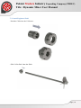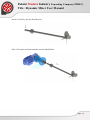
1
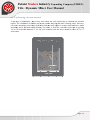
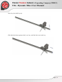
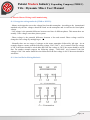
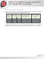
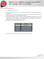
Pakzist Modern Industry Expanding Company (PMIEC) Title : Dynamic Mixer User Manual USER MANUAL FOR DYNAMIC MIXERS DESIGNED BY PKZIST MODERN ENGINEERING GROUP Add: Flat 5C , No .3 , SAYEH St JORDAN ( Nelson Mandela) Blvd , Tehran ,Iran Tel:+98 21 22651252 Fax:+98 21 22651253 Site: WWW.PMIEC.COM Page | 1 Pakzist Modern Industry Expanding Company (PMIEC) Title : Dynamic Mixer User Manual Contents 1- User Health And Safety ........................................................................................................................ 3 SAFETY CHECKLIST ............................................................................................................................ 4 2- Theory And Operation .......................................................................................................................... 5 3- Inspection Of Unit Upon Receipt .......................................................................................................... 6 4- Storage Requirements ........................................................................................................................... 7 5- Lifting and Handling ............................................................................................................................. 8 6- Vessel Mounting Methods .................................................................................................................. 10 6-1- Top-Entering, center mounted ......................................................................................................... 10 6-2- Top-Entering, off-center mounted ................................................................................................... 11 6-3- Top-Entering, Angle-Mounted Mixers ............................................................................................ 12 7- Installing And Alignment ................................................................................................................... 13 7-1- Install Agitator Drive ...................................................................................................................... 13 7-2- Install Agitator Shaft ....................................................................................................................... 14 7-3- Install Impellers ............................................................................................................................... 16 7-4- Alignment ........................................................................................................................................ 19 8- Electric Motors Wiring And Commissioning ..................................................................................... 21 8-1- Recognize wiring methods (STAR or DELTA) .............................................................................. 21 8-2- Star And Delta Wiring Methods ...................................................................................................... 21 8-3- Insulation classes for electric equipment ......................................................................................... 22 9- Shaft Run Out ..................................................................................................................................... 23 10- MAINTENANCE ........................................................................................................................... 24 10-1- GEARBOX MAINTENANCE ..................................................................................................... 24 11- Warranty and Contact ........................................................................................................................... 25 Page | 2 Pakzist Modern Industry Expanding Company (PMIEC) Title : Dynamic Mixer User Manual 1- User Health And Safety - All health and safety precautions must be followed to prevent physical injury to the operator. If a translation is needed, please contact a PAKZIST MODERN representative. - A mixer is a torque-generating device with rotating parts that can be hazardous. Any device containing generated torque can rupture, explode or discharge its contents if it is sufficiently over-torque and may possibly result in personal injury, property damage, environmental damage and death. All necessary precautions must be exercised to insure over-torque does not occur. PAKZIST MODERN will not accept responsibility for physical injury, damage or delays caused by a failure to observe the instructions in this manual. - Installation, operation or maintenance of the mixer unit in any manner which is not covered in this manual could cause damage to the equipment, serious injury or death. This includes any modification to the equipment or the use of parts not provided by PAKZIST MODERN. If there is a question regarding the intended use of the equipment, please contact a PAKZIST MODERN representative before proceeding. - Do not use the mixer equipment for a different application than originally specified without the approval of a PAKZIST MODERN representative. - Safety Equipment should be used in accordance with company regulations. The following safety equipment should be used within the work area: • Helmet. • Safety Glasses with shields or goggles. • Safety Shoes. • Protective Gloves. • Hearing Protection is recommended. - Always keep the work area clean and dry. - Follow safe lifting methods to avoid personal injury. - Avoid all electrical dangers. Be aware of risks from electric shock or arc flash hazards. - Utilize adequate lifting equipment and methods. - Electrical Connections and Regulations: • Refer to the motor nameplate for specific electrical operating information (Figure 4). • Electrical connections must be made by certified electricians in compliance with all international, national, state, and local regulations and codes. • Insure the product is isolated from the power supply and cannot be accidentally energized. • Make sure all thermal contacts are connected to a protection circuit according to product specifications. • All electrical equipment must be properly grounded (Figure 5). • During installation, service and repair, must always follow your company’s Lock-out / Tag-out procedure. Page | 3 Pakzist Modern Industry Expanding Company (PMIEC) Title : Dynamic Mixer User Manual - Critical fasteners should not be reused. Critical fasteners are all those that are used with torque control, for example blade bolts, shaft coupling bolts, pedestal fixing bolts, etc. When a fastener is disturbed, always replace it with a new one. Dispose of used fasteners. SAFETY CHECKLIST - This Installation, Operation and Maintenance Manual, assembly drawings, and any supplements must be reviewed and understood before commencing installation and operation. - All site rules must be observed for the installation and operation of this mixer. - Ensure all external connections are made in accordance with applicable codes of practice. - The mixer must be earthed (connected to ground). - Correct rotation must be checked prior to operation. - Do not exceed the operating pressures, temperatures, and other conditions for which the machine has been designed. - Do not operate the agitator unless all guards are securely fixed. Do not modify any guarding. Open tanks fitted with agitators must be provided with suitable guarding to prevent personnel contacting agitator-moving parts. The user is responsible for providing these guards. - Ensure mechanical seal setting clips are disengaged before operation. These clips should be retained for future use. - Ensure gas supply system, (if applicable) is correctly installed, pressurized and ready for operation. - Do not touch rotating components. - During servicing of the mixer, the motor must be isolated from the power supply and the supply locked out. - Do not operate the mixer for applications other than for its intended use. - Do not modify the mixer without reviewing the change with PAKZIST MODERN. It is unsafe to use non-standard parts Page | 4 Pakzist Modern Industry Expanding Company (PMIEC) Title : Dynamic Mixer User Manual 2- Theory And Operation There are a number of ways to perform mixing in vessels. Mechanical agitation, gas dispersion, and jets are often used. Due to the variety of processing needs and process objectives, a number of different mixer geometries have been developed. Fluid mixing is carried out in mechanically stirred vessels for a variety of objectives, including for homogenizing single or multiple phases in terms of concentration of components, physical properties, and temperature. The fundamental mechanism involves physical movement of material between various parts of the entire mass using rotating impeller blades. Over 50% of the world’s chemical production involve these stirred vessels for manufacturing high-added value products. These vessels are commonly used for: • Blending of homogeneous liquids such as lube oils, gasoline additives, dilution, and a variety of chemicals • Suspending solids in crystallizers, polymerization reactors, solvent extraction, etc. • Blending and emulsification of liquids for hydrolysis/neutralization reactions, extraction, suspension polymerization, cosmetics, food products, etc. • Dispersing gas in liquid for absorption, stripping, oxidation, hydrogenation, ozonation, chlorination, fermentation, etc. • Homogenizing viscous complex liquids for polymer blending, paints, solution polymerization, food products, etc. • Transferring heat through a jacket and/or internal coils for heating or cooling A conventional stirred tank consists of a vessel equipped with a rotating mixer. The vessel is generally a vertical cylindrical tank. Nonstandard vessels such as those with square or rectangular cross-section, or horizontal cylinder vessels are sometimes used. The rotating mixer has several components: an impeller, shaft, shaft seal, gearbox, and a motor drive. Wall baffles are generally installed for transitional and turbulent mixing to prevent solid body rotation (sometimes called fluid swirl ) and cause axial mixing between the top and bottom of the tank. Page | 5 Pakzist Modern Industry Expanding Company (PMIEC) Title : Dynamic Mixer User Manual 3- Inspection Of Unit Upon Receipt Step 1: Inspect crates. Upon receipt, inspect all crates and equipment for shipping damage. Report shipping damage to your local PAKZIST MODERN office or to the factory in Germany. A claim should be filed immediately with the carrier involved. Step 2: Uncrate. Check the contents. Do not uncrate the unit until you have read the Mounting & Installation section of this manual and looked at the assembly drawing shipped with the unit. Be careful in uncrating and handling. Do not discard the crating without making sure that all agitator parts have been removed. Correct assembly of this unit requires referring to both the unit assembly drawing and this manual. Step 3: Questions? Call PAKZIST MODERN. If the shipment is not complete or you do not understand What you have received, please contact your local PAKZIST MODERN office immediately. Page | 6 Pakzist Modern Industry Expanding Company (PMIEC) Title : Dynamic Mixer User Manual 4- Storage Requirements Do not remove protective packaging, desiccant, or any protective coatings applied to the wetted parts until the agitator is to be put into service. If the equipment is to be stored, do not stack crates. Store in a clean dry indoor location which is free from wide variations in temperature. The storage area should be free from vibration and excessive heat. Inspect for external rust at six-month intervals. Apply rust preventative as required. If the unithas been in storage for more than six months or subjected to adverse moisture conditions, themotor windings may have to be dried prior to operation. Short-Term Indoor Storage Agitators should be stored indoors in areas with no vibration and relatively constant temperatures and humidity. The factory storage preparations should be acceptable for up to six months storage. If the storage period will exceed six months, see Long-Term Indoor Storage section. Outdoor or Long-Term Indoor Storage Storage of agitators and motors outdoors is not recommended. If a unit is stored for an extended period indoors, stored outdoors or decommissioned, the following recommendations apply: 1. Install standpipe (not supplied) into breather [215] port and place breather into top of standpipe. Fill gear drive completely with oil. This allows oil to expand with temperature change without damaging the gear drive seals. 2. Rotate the motor and gear drive shafts 10 to 15 revolutions at least once per month to reduce the possibility of brinelling of the bearings and to redistribute bearing grease. 3. Apply a rust preventative to unpainted carbon steel surfaces and the agitator wetted parts to prevent corrosion during storage. 4. The unit should be covered to prevent damage by the elements but still allow free air circulation. CAUTION! Before placing an agitator in service the storage oil must be completely drained from the gear drive. Turn the gear drive upside down to completely drain. Failure to do this will result in oil being trapped in the "drywell" around the output shaft and could result in leakage at the output shaft seal. The gear drive should be filled with new oil and regreased as indicated in the Lubrication section of this manual. Page | 7 Pakzist Modern Industry Expanding Company (PMIEC) Title : Dynamic Mixer User Manual 5- Lifting and Handling Observe all lifting precautions. Failure to follow all lifting and handling precautions may result in serious injury! Unit weight is listed on the unit nameplate. Determine the weight of the unit to select an appropriate lifting method. If the weight of the Agitator exceeds manual lifting limits, mechanical lifting equipment must be used. The agitators can be lifted by the body using approved lifting straps together with suitable lifting equipment. Incorrect Methods Page | 8 Pakzist Modern Industry Expanding Company (PMIEC) Title : Dynamic Mixer User Manual Correct Methods Page | 9 Pakziist Mod dern In ndustrry Expannding Coompany (PMIEC C) Title : Dynaamic Mixer M User U Maanual 6- Vesssel Mountin ng Methodss 6-1- Toop-Enterin ng, center mounted m This typpe of installlation is the more usuall method off agitator moounting. If a mixer is center-moun c nted in tankk, what we see is a veery inefficieent flow paattern: the taangential velocities co oming from m the impelleer cause the entire fluidd mass to sppin (Fig. 1). Basically, the entire ffluid (and itss solids) mooves like a merry-go-ro m ound. In sollid suspensiion applicattions, the soolid particlees will swirrl around att the bottom of the tankk: no axial (top ( to bottoom) flow iss created to lift them upp and suspeend them inn the fluid. To prevvent gross vortexing v beehavior wheen low-viscosity liquidds are agitatted in a verttical cylindrrical tank wiith a centrallly mountedd impeller, baffles are often fittedd to the wallls of the veessel. Typiccally four bafffles will bee used, eachh having a width w equal to about onne-tenth of tthe tank diaameter. In soome cases thhe baffles are a mountedd flush withh the wall, although occasionally o y a small clearance is left betweenn the baffle and the waall. Baffles are a generallly not requiired with high-viscosity y liquids whhere gross voortexing is not n a probleem. Page | 10 Pakziist Mod dern In ndustrry Expannding Coompany (PMIEC C) Title : Dynaamic Mixer M User U Maanual 6-2- Toop-Enteringg, off-centeer mounted d In this type t of insttallation , mixers m may also reducee the swirl sufficientlyy to eliminaate the needd for baffles. The eliminnation of baaffles may avoid a produ uct hang-upp and make cleaning eaasier. Howeever, off-centter mountinng creates laarger hydrauulic loads th hat may reqquire a stronnger shaft an nd drive, stiiffer mountinng, and or a bottom steeady bearinng. The offsset, 0, from the centerliine of the taank is typiccally 1/6 to 1/4 1 of the taank diameteer, T. So, foor a 60″ diam meter tank the mixer w would be offfset 10” to 15” from ceenter. Page | 11 Pakziist Mod dern In ndustrry Expannding Coompany (PMIEC C) Title : Dynaamic Mixer M User U Maanual 6‐3‐Toop-Entering, Angle-M Mounted Miixers With axial-flow a impellers, an angulaar off-center positionn where thhe impelleer is mounnted approxiimately 10--15° from thhe vertical, can be useed. It’s worrth noting tthat the ang gular off-ceenter positionn used withh axial imppeller units is usually limited to those delivvering 3 HP H or less. The unbalannced fluid foorces generaated by thiss mounting can c becomee severe witth higher po ower. Warnin ng : The Prresent Typee of agitator should noot be installled angular . Page | 12 Pakzist Modern Industry Expanding Company (PMIEC) Title : Dynamic Mixer User Manual 7- Installing And Alignment For installing the agitator we absolutely recommend you to follow the schedule as below: A) De-assemble the shaft from Agitator Drive Install and level the agitator drive according to manual B) Install the impeller onto shaft C) At the final step , install shaft to the shaft holder If you follow the abovementioned list , you will not get any problem at all. 7‐1‐InstallAgitatorDrive The mixers are designed with a one-piece pedestal/mounting flange. Install the pedestal onto the structure with a customer supplied fastener set. In designing the structure to accommodate bending moment, the structure should be sufficiently rigid so that the agitator extension shaft will not move more than 1/2 inch (1.3 mm) per meter of length due to deflection of mounting system. Mount the agitator drive onto support structure using a similar lifting technique as described above. Attach unit to the support structure using customer supplied fastener set. The agitator drive assembly must be level within 1/2° (8.8 mm/m). Any angular misalignment may be corrected by machining the nozzle or pad level and flat, or shimming in the case of non flange-mounted units. Steady bearing units or units with close internal clearances are required to be level within 1/4° (4.4 mm/m) Page | 13 Pakzist Modern Industry Expanding Company (PMIEC) Title : Dynamic Mixer User Manual 7‐2‐InstallAgitatorShaft - Push the Collet into the Collet nut . - Slide Collet Pack Onto the Shaft Page | 14 Pakzist Modern Industry Expanding Company (PMIEC) Title : Dynamic Mixer User Manual - Put the Collet Key into the Shaft Keyway - Slide Collet pack and shaft smoothly into the Shaft Holder Page | 15 Pakzist Modern Industry Expanding Company (PMIEC) Title : Dynamic Mixer User Manual - Be sure the shaft was rested to the end of Shaft Holder. Tighten the Collet nut with Special wrench. 7‐3‐InstallImpellers - Slide Impeller onto agitator shaft up past the desired keyway location. Page | 16 Pakzist Modern Industry Expanding Company (PMIEC) Title : Dynamic Mixer User Manual - Place key into shaft keyway - Slide hub back down agitator shaft, over key, until the hub rests on the key. Page | 17 Pakzist Modern Industry Expanding Company (PMIEC) Title : Dynamic Mixer User Manual - Tighten ALLEN setscrew firmly onto the key. Torque to the value shown in Table below : Set Screws Permissible Torques REF Thread Diameter Friction Coefficient Tightening Torque (Nm) 1 2 3 4 5 6 7 8 9 10 11 12 13 14 15 16 17 18 19 20 M1.6 0.1 0.1 M2 0.1 0.2 M2.5 0.1 0.45 M3 0.1 1 M4 0.1 1.7 M5 0.1 3.4 M6 0.1 5.9 M8 0.1 14.5 M10 0.1 30 M12 0.1 50 M14 0.1 79 M16 0.1 121 M18 0.1 174 M20 0.1 244 M22 0.1 182 M24 0.1 234 M27 0.1 323 M30 0.1 445 M33 0.1 506 M36 0.1 651 Page | 18 Pakzist Modern Industry Expanding Company (PMIEC) Title : Dynamic Mixer User Manual Tighten all fasteners to values shown unless specifically instructed to do otherwise. Stainless Steel Fasteners tend to seize while being assembled (tightened) the risk of seizing is reduced by lubricating all fasteners at assembly with grease, oil or an anti-seize material. Bolt threads and contact surfaces of bolt heads and nuts should be lubricated. 7‐4‐Alignment The most frequent cause of mechanical difficulty with an agitator is improper alignment. It is imperative to heed the following guidelines: The agitator extension shaft is designed to run in a true vertical position. Do not angle or side mount the agitator unless it was specifically designed for angle mounting by PAKZIST MODERN. The agitator drive assembly must be level within 1/2° (8.8 mm/m). Any angular misalignment may be corrected by machining the nozzle or pad level and flat, or shimming in the case of non flange-mounted units. Steady bearing units or units with close internal clearances are required to be level within 1/4° (4.4 mm/m) Start up of the agitator with the turbine impacted in solids is beyond the scope of these recommendations. The mounting structure must be rigid enough to meet the requirements described in previous section. During operation of the agitator, the fluid motion in the vessel produced by the rotation of the turbine impeller can exert significant forces and moments on the agitator extension shaft. The forces and moments produced by the turbine rotating in a fluid are; torque, turbine thrust (up or down) and turbine hydraulic (side) force. The hydraulic forces acting on the turbine generate moments, which act on the shaft and are transmitted to the agitator drive. Because of the random nature of the forces and the rotation of the shaft, the direction of these forces is constantly changing. A pitched blade or axial flow turbine will impart an upward or downward thrust depending on if it is a down or up pumping turbine, respectively. The thrust force is generally less than the weight of the unit. The agitator has been designed to accommodate all of the forces mentioned, and as a result, the forces are transmitted directly to the mounting support. The support structure must be rigid enough to support the agitator weight and the live agitator reactions resulting from the torque, thrust and bending moment. The structure should be sufficiently rigid that, assuming a perfectly rigid agitator extension shaft, the vessel deflection will not cause the impeller end of the shaft to deflect more than 2.6 mm per meter of shaft length. For high-speed units a greater level of stiffness should be Page | 19 Pakzist Modern Industry Expanding Company (PMIEC) Title : Dynamic Mixer User Manual achieved. An agitator mounted on a structure that is adequately rigid should typically have a vibration velocity of less than 9 mm / sec measured at the furthest end from the drive shaft. THIS INFORMATION IS INTENDED AS A GUIDE, AND DOES NOT RELIEVE THE USER OF COMPLETELY ANALYZING THE ENTIRE MOUNTING SYSTEM. EXTREME APPLICATIONS OR DESIGNS MAY REQUIRE SUPPORT STIFFNESS GREATER THAN THE RECOMMENDATIONS PROVIDED HEREIN. CONSULT CHEMINEER INSIDE SALES FOR DESIGN GUIDANCE. Page | 20 Pakzist Modern Industry Expanding Company (PMIEC) Title : Dynamic Mixer User Manual 8- Electric Motors Wiring And Commissioning 8‐1‐Recognizewiringmethods(STARorDELTA) - Motors are designed to run at the voltage listed on their nameplate. According to the international standard only the line voltages should be listed on the nameplate and it could not be listed phase voltage. - Line voltage is the potential difference between two lines of different phases. This means there are actually 3 line voltages on a three-phase system. - Phase voltage is the potential difference between a line and neutral. Phase voltage could be changed to line voltage by multiplying to √3 . - Normally there are two range of voltages on the motor nameplate followed by Y/∆ sign . As an example suppose a motor with the following voltage: 220 V/380 V ∆/Y It means if the line voltage is 220 V the motor should be wired delta and if the line voltage is 380 V the motor should be wired Star. For another example suppose the following voltage : 380V/690V ∆/Y It means if the line voltage is 380 V the motor should be wired delta and if the line voltage is 690 V the motor should be wired Star. 8‐2‐StarAndDeltaWiringMethods Page | 21 Pakzist Modern Industry Expanding Company (PMIEC) Title : Dynamic Mixer User Manual 8‐3‐Insulationclassesforelectricequipment Insulation systems are rated by standard NEMA (National Electrical Manufacturers Association) classifications according to maximum allowable operating temperatures. Maximum Temperature Operation Temperature Tolerance Allowed Class o o C F A B F H 105 130 155 180 221 266 311 356 Allowable Temperature Rise at full load 1.0 service factor motor o C 60 80 105 125 AllowableTemperature Rise 1.15 service factor motor o C 70 90 115 - Allowable temperature rises are based upon a reference ambient temperature of 40oC. Operation temperature is reference temperature + allowable temperature rise + allowance for "hot spot" winding. Page | 22 Pakzist Modern Industry Expanding Company (PMIEC) Title : Dynamic Mixer User Manual 9- Shaft Run Out Check the installed extension shaft run out. Place dial indicator on the side of the extension shaft at the bottom. Manually turn the exposed low speed shaft at the top of the reducer one full turn. Total extension shaft run out should not exceed .005" per foot (0.42 mm per meter) FIM (Full Indicator Movement) of shaft length. If the shaft run out is excessive, the shaft can be restraightened in the field. Rotate the shaft to the maximum positive indicator reading . Apply heat to the shaft at a point 180o from the indicator and just below the first in-tank shaft coupling or just below the mounting surface if there is no in-tank coupling. As heat is applied to the shaft (do not allow surface temperature of shaft to exceed 500oF[260oC]), the shaft will move toward the indicator. After the shaft has moved .030-.060"(.76-1.52mm), remove the heat and the shaft will begin to move away from the indicator. The shaft will draw more than it moved initially, and as a result will be straightened. After each heating cycle, recheck the shaft until run out is within tolerance. Do not heat in the same location. Move up or down 2-3" (50-70 mm) to avoid reheating the same location. Page | 23 Pakzist Modern Industry Expanding Company (PMIEC) Title : Dynamic Mixer User Manual 10- MAINTENANCE 10‐1‐GEARBOXMAINTENANCE The precise machining of the unit's internal components ensures correct operation with minimum maintenance. Periodic control of external cleanliness, above all in areas most concerned in cooling; periodic checks for lubricant leaks, especially around the seal rings. For life lubricated units, without oil plugs, no special maintenance is required except for that indicated in the previous point. For other units, maintenance is nonetheless very limited, since it consists solely in an oil change to be done after 10,000 hours of operation. The oil change depends on the operating conditions and type of duty The oil types that could be used are listed as below : COMPANY MODEL ENI SHELL ESSO MOBIL CASTROL BP TELIUM VSF320 TIVELA OIL S320 S220 GLYGOYLE 30 ALPHASYN PG320 ENERGOL SG-XP320 It is highly recommended to refer gearbox manual for more information. Page | 24 Pakzist Modern Industry Expanding Company (PMIEC) Title : Dynamic Mixer User Manual 11- Warranty and Contact Warranty: All equipment or parts covered by this manual are guaranteed free from defective material and workmanship for a period of twelve (12) months from date of shipment, under normal use and service. This warranty does not cover failure of normal wear parts unless the failure of such part has resulted from defective material and workmanship will repair or replace, at its option, any equipment which has been found to be defective and is within the warranty period, provided that the equipment is shipped, with previous factory authorization, freight prepaid, to PAKZIST MODERN's plant in Iran. All return shipments are made FOB PAKZIST MODERN's factory. PAKZIST MODERN is not responsible for removal, installation, or any other incidental expenses incurred in shipping the equipment to or from PAKZIST MODERN. In the case of components purchased by PAKZIST MODERN, and incorporated in the equipment, the component manufacturer's guarantee shall apply. NOTE: Any modifications or corrective work done to the equipment which were not specifically authorized in writing by PAKZIST MODERN shall void this limited warranty, and PAKZIST MODERN shall accept no liability for any of the corrective work or expenditures which were conducted without their prior, written authorization. PAKZIST MODERN shall not be held liable for any further cost, expense, or labor to replace equipment or replaceable parts, or indirect or consequential damages. With the exceptions of the limited warranty set out above, there are no other understandings, agreements, representatives, or warranties implied (including any regarding the merchant-ability or fitness for a particular purpose), not specified herein, respecting this agreement or equipment, hereunder. This contract states the entire obligation of PAKZIST MODERN in connection with this transaction. Contact: For questions, concerns, or comments, we strongly recommend contacting the sales representative that supplied your equipment. Otherwise your may email us or visit our website. We typically respond same day. Thank you for choosing PAKZIST MODERN. We look forward to a long standing relationship with you, providing high quality custom equipment! Page | 25