1
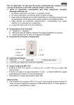
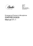
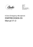
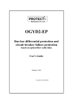
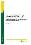
LineTroll 111K PN: 04-1110-00 User Manual TABLE OF CONTENTS Page: 1. 2. LINETROLL 111K OVERVIEW ............................................3 FUNCTIONAL DESCRIPTION ................................................ 4 2.1. Adaptive detector .................................................................................... 4 2.2. Operation criteria ................................................................................... 4 2.2.1 Inrush blocking time 2.2.2 Fault current passage 2.2.3 Circuit Breaker (CB) tripping 2.3. Indication ................................................................................................. 5 2.3.1 Main Flash White “Xenon-like” 2.3.2 Red LED – Transient Fault 2.3.3 Yello LED – Low Battery 2.4. Reset criteria ............................................................................................ 5 2.5. Battery lifetime /maintenance ................................................................ 6 3. 4. APPLICATION ............................................................................ 7 APPLICATION NOTES ............................................................. 8 4.1 Line switching .......................................................................................... 8 4.1.1. Connecting a healthy line 4.1.2. Connecting a faulted line when indicator is not indicating 4.2. Faults ........................................................................................................ 8 4.2.1. Permanent faults 4.2.2. Transient faults 4.2.3. Second fault while indicating a previous fault 4.3. Automatic reclosing ................................................................................. 9 4.3.1 Not successful reclosing 4.3.2 Successful reclosing 4.4. Fused lines ...........................................................................10 4.5. Multiple faults ......................................................................10 4.6. Capacitive discharges .............................................................10 4.7. Setting and location ...............................................................11 4.8. Sensitivity .............................................................................11 4.8.1 Earth faults 4.8.2 Short circuit faults 4.8.3 Recommended distances 5. 6. PROGRAMMING ..................................................................... 14 MAINTENANCE ......................................................................... 15 6.1. Battery replacement................................................................................ 15 7. 8. 9. INDICATOR HOUSING ........................................................... 15 LT 111K TECHNICAL SPECIFICATION ............................. 16 INDICATION ..........................................................................17 9.1 Flashing sequences during fault: 10. DIMENSIONS ............................................................................. 19 APPENDIX 1: MOUNTING INSTRUCTION LINETROLL 111K User Guide January 2012 Page 2 of 21 1. LINETROLL 111K OVERVIEW LINETROLL 111K is used to locate short-circuit- and earth faults in overhead line distribution networks. LINETROLL 111K is a pole mounted fault indicator monitoring all 3phases based on changes in electric- and magnetic field. The indicators are placed at strategic locations along the line such as after branching points and sectionalisers. It mounts on the pole, 3-5 meters below the conductors, by means of screws or wrappingbands. Live line mounting is done safely, easily and rapidly. Upon detecting a fault on the line, the indicator gives off a high visibility White ‘Xenon-like’ flash from two Super Intensive LED’s. This flash can be seen within 200-300 metres distance in bright day-light and 2-3 km at night. The lens of the indicator allows for uniform 360 degrees monitoring. Fig. 1. Indicators during a fault situation Upon fault sensing, all indicators installed between the feeding substation and the fault will operate. The indicators placed behind the fault remain idle. LINETROLL 111K provides fast fault location enabling reduction in outage times. This represents enhanced service to the customers thereby improving the utilities image. Another important aspect of using fault indicators is that unnecessary operations of circuit-breakers and sectionalisers to locate faults are avoided. This way the indicators help to reduce wear and tear as reclosing cycles causes stress to the switchgear. LINETROLL 111K User Guide January 2012 Page 3 of 21 2. FUNCTIONAL DESCRIPTION LINETROLL 111Ks fault sensing is based on detection of the electromagnetic field below the conductors. The unit is fully self-contained, no external transformers or connections of any kind is required. To determine whether or not the line is faulted, the indicator is looking for a specific sequence in the line conditions to happen before it starts flashing. The general sequence is as follows: (ref. fig.2) 1. The line should be energised for at least 5 seconds. 2. The line current should increase rapidly above the value set by the user (the nominal trip level). 3. The line should be de-energised. Slow variations in load current will not affect the detector. A fault current will cause a rapid increase in the B-field which the detector will respond to. The detector will now require that two conditions are satisfied: 1. The relative increase dB is greater than a certain level. 2. The absolute increase dB T is greater than a pre-set value. The second condition is the trip level which can be set by the user to four different values; 4, 7, 15 or 50A. The corresponding B-field can be found by using the formula: BT=0ISET/(2d) where 0=410-7 (free space permeability) ISET= 4, 7, 15 or 50A d= 3m (distance conductorindicator) Example: ISET=7A => B=0.47T 2.2. Operation criteria As mentioned the indicator is looking for a specific sequence. This sequence requires the following criterion to be fulfilled to activate the indicator: 5s Fig. 2. Fault sequence However, the user might program the criteria for operation to suit his local requirement by manipulating a bank of micro-switches inside the indicator. 2.2.1. Inrush blocking time The line voltage has to be present for approximately 5 sec. before any fault current will be detected. This blocking time avoids indication upon magnetising inrush currents during line energising. 2.1 Adaptive detector The measured magnetic field (=B-field) is applied to an adaptive dB/dt detector. This detector automatically adjusts to the normal conditions on the line. 2.2.2. Fault current passage The fault current has to generate the required increase in the magnetic field as described in section 2.1. LINETROLL 111K User Guide January 2012 Page 4 of 21 If these two criteria are fulfilled the fault is detected and stored. Whether the fault should be indicated or not depends on what happens on the line and how the indicator is programmed. 2.2.3. Circuit Breaker (CB) tripping Setting: CB-trip enabled (sw 5 = on): Line de-energised within 5 sec: Indication Line NOT de-energised within 5 sec: No indication Setting: CB-trip disabled (sw 5=off): Indication not dependent on de-energised line. Note: If programmed for voltage reset (sw#6) the indicator reset 30s after line is re-energised. 5s 2.3.1. Main Flash White “Xenon-like” This is the main indication; Permanent faults. Two Super Intensive LED’s flash a 0,4s burst every 3s. 2.3.2. Red LED - Transient Fault Transient faults will be indicated with the Red LED’s flashing every 5s. The transient indication flash for 24 hours and then reset. After 12 hours the flashing frequency will change to 1/10sec. Transient indication can be switched off with switch 7. 2.3.3 Yellow LED - Low battery When the battery has less than 80% of the capacity left, or has been in operation more than 9 years, the Yellow LED’s start flashing every 6sec. The flash continues until the battery counter is reset. See 2.6.1. 5 2.4. Reset criteria 5 The indicator can be reset in three different ways: A. Automatically when the line is energised B. Automatically by internal timer C. Manually by a magnet Fig. 3. CB-tripping If LT 111K is to be used in a network with no tripping due to earth fault the CBtripping must be disabled to obtain indication of earth fault. If these two criteria are met in the correct sequence, the indicator starts indicating. 2.3. Indication Three different coloured LEDs; White, Red and Yellow which are duplicated (both side of the PCB) in total 6 LED’s, gives a 360° visibility of fault- and status-indication. A. Automatic - Voltage reset The main indication will reset 30s after a stable (continuously) line-voltage is detected. Voltage reset can be switched on/off with switch 6. If Voltage reset = OFF, also transient faults will be indicated as permanent faults; white Xenon-like led. If Voltage reset = ON; transient faults will be indicated with the red LED’s only (if switch 7=ON). LINETROLL 111K User Guide January 2012 Page 5 of 21 B. Automatic timer-reset Automatic reset of the main flash can be programmed by switch 3 and 4; to 1.5, 3, 6 or 12 hours. Note: The red LED’s, transient indication, will always flash for 24h (if switch 7=ON) C. Manual reset LINETROLL 111K can be reset by placing a magnet on the indicator "RESET" spot for minimum of 1s. Fig.6. Initial battery capacity as a function of temperature. A special hot-stick-attachable tool TBX-10, is available for resetting of the indicator from the ground when mounted on a pole. The same magnet or tool can be used to activate the indicator on site, for testing. See appendix 1; Mounting instructions. 2.5. Battery lifetime / maintenance A 3,6V 16,5 Ah Lithium battery powers the LINETROLL 111K. When idle, the indicator draws a few micro-Amps only, giving up to 7-10 years battery lifetime in normal service depending on temperature and operational hours. See fig 6 & 7. Fig.7. Remaining battery capacity as a function of average cell temperature and time. When the unit is activated, approximately 5mA are consumed, giving more 2000 flashing hours. The battery is fitted with a connector for simple replacement. 2.6. 1 Resetting battery counter When replacing the battery, the battery counter has to be reset according to the procedure in the mounting instruction (the last 2 pages in this document). LINETROLL 111K User Guide January 2012 Page 6 of 21 3. APPLICATION The application of LINETROLL 111K usually requires a previous line survey so that the best use of it may be obtained. For the best economic benefit it is recommended that the indicators are used: In easily accessibly line points for easy monitoring of the indicator in case of fault, for instance near the road. It is advisable to take binoculars. Before and after line points difficult to reach (mountains, woods, etc.) to quickly locate the fault. Next to line branching points, to easily locate the damaged branch. When installing indicators at such points, the use of indicators in every branch is recommended in order to provide complete information in the event of fault. Not doing so may cause confusion since there may be an indication in a branch due to a nonpermanent fault while another branch without indicator may be faulty yet considered healthy. Do not use LINETROLL 111K on: 1. Poles: with underground cables with T-offs with double circuit lines with sectionalisers with distribution transformers closer than 300 metres to 220-440 kV lines closer than 150 metres to 132 kV lines closer than 100 metres to 66 kV lines closer than 50 metres to 33 kV lines closer than 35 metres to 22 kV lines 2. Lines protected with fuses 3. Ring lines or multiple feed lines. 4. Line points where capacitive discharge current from the network downstream exceeds trip level can activate the indicator. Near line points with sectionalisers to rapidly pinpoint and isolate the fault to facilitate rapid reconnection the healthy sections. LINETROLL 111K is suitable in: 6-132kV distribution networks. Radial lines. Isolated-neutral networks. Solidly-earthed-neutral networks. Resistance-earthed-neutral networks. Single and 3-phase network LINETROLL 111K User Guide January 2012 Page 7 of 21 4. APPLICATION NOTES The aim of this section is to describe how the LINETROLL 111K indicator behaves in different service situations and network events. tripping), will be indicated with the Main flash (White LED) only. The time out for the Main Flash can be set by the user to 1.5, 3, 6 or 12 hours. 4.1. Line switching 4.1.1. Connecting a healthy line As the magnetising inrush current of a line can be very high, the indicator is provided with a 5 seconds blocking of the dB/dt sensor which prevents it from being activated until the line current is stabilised. Once the blocking time has elapsed, the indicator is enabled for fault detection. See fig. 2. 7 7 4.1.2. Connecting of faulted line when indicator is not indicating Fig.9. Permanent faults. This will not cause any indication for the same reason as for connection of a healthy line. The blocking time will avoid any indication. 4.2.2. Transient fault Transient fault cleared within the last automatic reclosing which cause the line to be permanently energised > 30s before timeout of 70s, will be detected by the Red LED’s. If Transient fault is switched OFF (sw7) it will reset after 70s 40-70sec Fig.8. Connecting a faulty line 7 4.2. Faults 7 4.2.1. Permanent fault A fault that has been confirmed to be a Permanent Fault (after 70s form the CBFig.10. Transient fault LINETROLL 111K User Guide January 2012 Page 8 of 21 4.2.3 Second fault while indicating a previous fault If a second fault occurs whilst the LT111K is indicating a previous transient fault, all timers reset and start counting from zero. The LED will then flash for another 24 hours from the second fault occurred. Fig.12. Reclosing upon a faulted line. 4.3.2. Successful reclosing The operation due to a successful reclosing depends on the setting of the voltage reset as well as the state of indication: If indicating a Permanet fault: 1. Voltage reset (sw6) = OFF Indication until time ut from the internal timer; 1.5 – 12hours. Fig.11. Second fault while indicating a previous fault. 4.3. Automatic reclosing An automatic reclosing will not activate a non-flashing indicator. If the indicator is indicating a previous fault the operation due to a reclosing depends on whether the reclosing is successful or not. 2. Voltage reset = ON Main flash resets after 30seconds If indicating a Transient fault: The Transient indication will not be affected of the return of voltage. 4.3.1. Not-successful reclosing Closing a breaker onto a fault leads to another trip almost instantly. As the activated indicator needs 30 seconds with stable line voltage in order to reset, the indicator remain flashing. Fig.13. Successful reclosing LINETROLL 111K User Guide January 2012 Page 9 of 21 4.6. Capacitive discharges 4.4. Fused lines One operation criterion is that, after a fault, a three-phase disconnection of the line has to be carried out. If, instead of a threephase trip, a fuse operates in one or two phases, the voltage of the healthy phase might reset the indicator. This is true for indicators placed before the fuse as well as after it. When the criterion CB tripping is enabled, LINETROLL 111K is not activated unless the fault causes a three-phase trip in the feeding within 5 seconds after the occurrence of the fault. If CB tripping is disabled, the indicator is activated but will reset after 30 sec., unless the fault causes a three-phase trip in the feeding end within this time. If the voltage reset is switched off, the indicator will continue flashing until it is reset manually or after the automatic timer period has elapsed. The LINETROLL 111K indicator is not directional, it therefore detects current without discriminating its direction. In case of an earth fault, the capacitive energy of the network discharges in the fault point. It should be checked that the capacitive discharge current downstream the indicator is below pre-set trip level in order to avoid the indicator erroneously activating upon earth faults. If the total capacitive current exceeds the trip level, it is advisable to change the trip level or install the indicators in the branching points instead of in the main line. The capacitive discharge of a branching point is limited by its own capacitance, while in the main line the capacitive current of all the branches downstream the indicator is added. Underground cables have larger capacitance than overhead lines. This has to be taken into account when an overhead line feeds an underground cable. The following simplified formula may be used to estimate the capacitive discharge current of a line: 4.5. Multiple faults Multiple faults sometimes occur. Defective network components may burn or break due to the electro-dynamic force of the fault current and cause a second fault. Another cause of multiple faults in isolated networks is the arise in voltage in the healthy phases with reference to ground. The voltage may reach up to 1.7 times the nominal voltage. Weak insulators may not withstand such a large voltage increase, and second earth fault may occur. This kind of fault may be difficult to trace as they often are non-permanent and only appear in situations like the ones mentioned here. Ic = U = LL = LC = K = Capacitive current in A Nominal voltage in kV Overhead line length in km Cable length in km 10; for oil impregnated cables 5; for PEX cables 3; for PVC cables In order to avoid the LINETROLL 111K being activated by an earth fault upstreams the indicator, the following criteria have to be met. (1) Ic < ISET Ic = capacitive discharge current downstream the indicator. ISET = max. sensitivity for earth fault; 4,7,15 or 50A. LINETROLL 111K User Guide January 2012 Page 10 of 21 To estimate the capacitive discharge current at any line point, you have to calculate the contribution from all the overhead lines and underground cables lengths only beyond that point. Comparing (1) and (2) gives the limit for the ISET: IC < ISET < I0 - IC 4.8. Sensitivity 4.8.1 Earth faults LINETROLL 111K monitors the resulting magnetic field under the line. The sensitivity for earth faults is a function of the following variables: Fig.14. Capacitive discharge current calculation example. 4.7. Setting and location In network with the feeding transformers neutral isolated from the earth, earth fault current normally is low. In such network it is important to do a thoroughly analysis of the network to find the correct installation and settings. Two criteria must be satisfied: In order to avoid false indication due to discharge current during earth faults the following criteria have to be met: (1) IC < ISET IC = Capacitive discharge current behind the indicator. ISET = maximum sensitivity for earth fault; 4,7,15 or 50A. To obtain correct indication during earth fault the following criteria have to be met: (2) ISET < I0 - IC I0 = Total earth fault current in the net. 1. The trip level set on the indicator; 4, 7, 15 or 50 A. (See section 2.1) 2. Load current of the line when the fault occurs. 3. Line configuration on the pole where the indicator is located. 4. The distance between the conductors and the indicator. As mentioned in section 2.1. the maximum earth fault sensitivity can be set to 4, 7, 15 or 50A. These values correspond to an earth fault occurring on a line with no load current and the indicator located 3m below the faulty conductor. When the load current increases, the sensitivity for earth faults decreases. Increasing the distance (d), between the sensor and the conductors results in a lower sensitivity at low load however the sensor keeps this sensitivity at a higher load. See the diagram in fig. 15 showing the maximum earth fault current sensitivity for different settings (4, 7, 15 and 50A), as a function of load current. The sensitivity for three different distances is plotted in the diagram. LINETROLL 111K User Guide January 2012 Page 11 of 21 Fig.15. Maximum sensitivity for earth fault current as a function of load currents and distance from conductors. Example: The indicator is supposed to be installed on a pole where the: nominal load current is 30A, discharge current (Ic) from the line behind is 8A the expected earth fault current (Io-Ic) = 35A According to (1) and (2) in point 4.1. the indicator should be set to: 8A < ISET < 35 => ISET = 15A. The axis for ISET = 15A and a load current ILOAD = 30A indicate a sensitivity for earth fault of approximately 20A. A load current of 150A reduce the sensitivity to 45-50A at 3m. By increasing the distance to 5m the sensitivity is improved to approximately 35A. 4.8.2 Short circuit faults Detection of short circuit faults has the same criteria as earth fault detection except from the trip level. On the horizontal axis in the diagram there are three points named; IL3, IL4 & IL5. The figures for the corresponding ISET on the horizontal axis, indicates the minimum detectable short circuit current assuming that the fault is a 3-phase short circuit. Example: Distance d=4m. ISET=15A. From the curve we find that IL4 = 130A for ISET= 15A. The criteria for detection of a 3-phase short circuit will then be: 1. 2. ISC > 130A ISC > 2 x ILOAD (=100% increase) Normally short circuits cause high fault currents. In case of a 3-phase short circuit near the end of a long line, the conductor impedance may cause a great reduction of the fault current. This is important to be considered if high values for ISET are used ; 15A or 50A. LINETROLL 111K User Guide January 2012 Page 12 of 21 4.8.3 Recommended distances The fault current which is necessary to generate a sufficient increase in magnetic field depends on; i) the indicators distance from the conductor, ii) the line configuration and iii) the load current. The distance from the conductors is measured from the lowest conductor. Example: The normal load current is 30 amps. The LT111K is set to: ISET= 15A. Then we have :ILOAD/ISET = 30 / 15 = 2. Optimal distance for horizontal according to the table is: 3m. For triangle configuration the optimal distance is 4m. Fig. 16. Distance from conductors The table below show the distance d, giving the maximum sensitivity for earth faults as a function of load current, for two different configurations. Table 1. Optimal distance; d. LINETROLL 111K User Guide January 2012 Page 13 of 21 5. PROGRAMMING Programming of the unit is done from a switch-bank on the printed circuit board. See the figure below for switch ON/OFF definition. Switch combinations which are not shown should not be used. 5.1. Sensitivity The maximum sensitivity (lowest detectable current) for earth fault current can be set to 4 values: 4, 7, 15 or 50Amps. Sw.# 1 2 0 0 0 1 1 0 1 1 Max sensitivity For earth faults 4 Amp. 7 Amp. 15 Amp 50 Amp 5.2. Timer reset Timer reset of the Main flash can be set 4 values; 1.5, 3, 6 or 12 hours. Sw.# 3 4 0 0 0 1 1 0 1 1 Timer reset 1.5 hours 3 hours 6 hours 12 hours Timer reset of the Red LED (Transient Indication) is fixed to 24 hours. 5.3. CB tripping within 5 sec. If enabled, the line must be de-energised within 5 sec. after the fault occurrence to start indication, both for transient and permanent faults Sw 5 OFF ON CB tripping within 5 sec. Disabled Enabled 5.4. Voltage reset. When Voltage reset is ON, an ongoing fault indication will be reset automatically when the indicator detect a stable and continuously voltage for 30s. If Voltage reset is OFF, the indication will continue independent of linevoltage, until the timer reset expires. Sw 6 OFF ON Voltage Reset Disabled Enabled 5.5. Transient Indication When sw 7 is ON, a transient fault (=successful auto-reclosing within 70s) will be indicated with the Red LED for 24 hours. If another transient fault occurbefore expire of the 24hours, it restart for another 24hour period. Sw 7 24hours Transient Indication OFF Disabled ON Enabled 5.6. Minimum Fault Duration (filter) To avoid indication on switching transients, the indicator has a filter which set the minimum duration for a fault to be detected and indicated as a real fault. Sw 8 OFF ON Filter 20ms (1 cycle @50Hz) 60ms (3 cycles @ 50Hz) This filter must be coordinated with the tripping time of the Circuit Breaker (=CB). If the CB disconnect the line/feeder faster than 60ms; choose 20ms (sw6=OFF) to ensure indication. Note: RESET the indicator after switch changes! LINETROLL 111K User Guide January 2012 Page 14 of 21 6. MAINTENANCE 7. INDICATOR HOUSING It is advisable to inspect the indicator once a year or 1 year after it was last activated. The inspection should include a functional test to show that the flashlight frequency is normal. NORTROLLs TBX-10 test- and reset-tool is very useful for the test purpose, although any magnet can be used. See appendix 1; Mounting Instruction. The indicator housing is made of high strength plastic. The material is highly UV stabilised and is flame retarding. The lens material, in addition, has excellent optical characteristics. An O-ring with silicon grease joint is used to provide a good seal between the upper cap and the lens. The bracket is made of aluminium. 6.1. Battery replacement. Necessary tool: 5-10 mm screwdriver. The battery is fitted into the top cap of the indicator housing. To replace the battery, remove the indicator from the bracket. Unscrew the top-cap and disconnect the battery from the electronics board by pulling the battery connector. The spare battery comes complete with a new top-cap with a label indicating the year of manufacturing. Connect the new battery and replace the top cap ensuring that the arrows are aligned before entering. Fix the indicator to the bracket. The top cap of the indicator has a colour coded label indicating the year of manufacture. Fig.19. Top-cap colour coding versus the year of manufacture. Fig.18.Allign the arrows before assembling the LT-111K together after battery replacement. LINETROLL 111K User Guide January 2012 Page 15 of 21 8. LT 111K TECHNICAL SPECIFICATIONS MAX. SENSITIVITY FOR MAGNETIC FIELD (B-FIELD): ISET 4A 7A 15A 50A B-field: T 0.27 +/-20% 0.47 ’’ 1.00 ’’ 3.33 ’’ RESET: 1) Voltage reset, delayed 30 sec. Can be disabled 2) Timer reset of Main Flash; 1.5, 3, 6 or 12 hours. 3) Manual reset by magnet. CURRENT CONSUMPTION: BLOCKING TIME FOR INRUSH: 5 seconds Non-activated: Activated Transient Ind: Activated Main flash: 200uA 500uA 5mA BATTERY: INDICATION CRITERIA: 1) Line energised for more than 5 seconds - followed by a 2) Line current increasing by at least 100% within 20 ms (or 60ms) and reaching a level that exceeds the programmed trip level - followed by a 3) Circuit Breaker tripping within 5 sec. after the fault occurrence (can be disabled). REQUIRED FAULT DURATION: 1) 60msec or 2) 20msec INDICATION: 1) Main Flash; White Super Intensive LED indicating permanent faults, flashing burst/strobe every 3sec 2) Red High intensity LED’s; indicating transient fault 3) Yellow LED; indicating Low Battery *) If a new fault occurs after the timer reset of the Xenon flash but before the 24 hour LED flashing reset; both timers restart. Lithium battery; 3.6V 16.5Ah at 5mA @ 20oC, type KBB-12. Battery replacement every 7-10 years or more than 2000 operational hours, whichever comes first. AMBIENT AND STORAGE TEMPERATURE: -40oC to + 74oC HOUSING MATERIAL: Lens: LEXAN Top-cap: Super-tough nylon BRACKET MATERIAL: Aluminium WEIGHT: 1 unit: 0.526 kg (battery and bracket incl.) 1 complete box contains 2 complete LT111K’s: Weight: 1150 grams. Volume: 3,2 dm3 (270 x 170 x 70 mm) LINETROLL 111K User Guide January 2012 Page 16 of 21 9. INDICATION Test: Place a magnet/test-tool on the yellow RESET-spot. After a 5s start up sequence; rapid yellow & red flash, it start to indicate Transient Fault; flashing the Red LED (1/5sec), for 25s, followed by the Main Flash (White Super Intensive LED) until magnet/Test tool is removed. t=0 Until magnet is removed 5 Red flash (1/5sec) 10 rapid Flash R+Y 5s Initial flash (R+Y) 30s Transient Fault (Red) Permanent Fault *) Main flash (White) (1/3s) *) Note: When conducting a test-sequence, the Red LED may remain ON during the Permanent fault indication. This is normal, and will not occur during real fault detection. Reset/status When magnet/test-tool (TBX-10) is removed form the RESET-spot, the indicator resets and enter a 30s status indication. During the status indication, the Yellow + Red LED’s indicates the prescense of linevoltage. If the indicator do not detect any linevoltage, only the Red LED’s are flashing. Reset/status indication can be initiated by the following operations; 1) connecting the battery, 2) magnet/test-tool on the RESET spot for min 1s and then removed, or 3) removing the magnet/test-tool from position after conducting a test-sequence. Line-voltage No Voltage Line-voltage present Flashing freq: 1/2second 30s RESET Low battery: When battery has less than 80% of the capacity or the indicator has been in operation for more than 9 years, the “Low-battery" LED (Yellow) start flashing, until battery-counter has been reset. 6s Until reset battery counter LINETROLL 111K User Guide January 2012 Page 17 of 21 9.1 Flashing sequences during fault: Transient fault: f=1/10sec 12 hours 40sec NO INDICATION Permanent fault: Transient fault followed by a permanent fault 40sec LINETROLL 111K User Guide January 2012 Page 18 of 21 10. DIMENSIONS Fig.20. Dimensions LINETROLL 111K User Guide January 2012 Page 19 of 21 LINETROLL 111K (PN: 04-1110-00) MOUNTING INSTRUCTION General Linetroll 111K mounts on the pole 3-5meters below the conductors as shown in figure 3. The indicator can be installed on a live line. Before mounting Linetroll 111K is a programmable fault current indicator, and must be programmed before installation. Mounting & programming: 1. Unscrew the top cap from the lens, and set the required switch combinations according to programming tables on next page. Fig.1 Entering top cap and lens French screws for fixing bracket to pole 2. Connect the battery. If the indicators have been in store for some time, the battery voltage may be low. To ensure the battery has reached the normal operating voltage the indicator should be left to flash for about 30 minutes, by which time the voltage will be restored to required value. Slots for steel band (concrete poles) 3. Replace the top cap by entering the top cap arrow aligned with the arrow on the lens label. 4. Mount the bracket to the pole with the attached French screws or in case of concrete poles, a steel band through the rectangular cut outs (see figure) can be used. Consult the User Guide for correct distance from the conductors. Fig.2 Fixing of bracket to the pole 5. Fix the indicator to the bracket using the supplied screws. Fig.3 Mounting the LT-111K on a pole LINETROLL 111K User Guide January 2012 Page 20 of 21 PROGRAMMING OF LT-111K (Prod no: 04-1110-00) Manual Test/Reset: 1. Fix the test/reset tool TBX-10, on a stick and guide it between the arms of the bracket until it stops in upper position, see figure right side. The magnet on TBX-10, shall then be in level with the yellow spot on the indicator label marked: “RESET”. 2. The indicator starts the TEST-sequence; a. 25sec Transient fault indication; flashing red led, followed by b. Permanent fault indication; White strobe flash until TBX-10 is removed. 3. Remove the TBX-10, and the indicator RESET’s followed by 30sec status indication; Yellow+Red if line energized, Red only if line is de-energised. PROGRAMMING Max sensitivity For earth faults Sw.# 1 2 0 0 4 Amp. 0 1 7 Amp. 1 0 15 Amp 1 1 50 Amp Sw.# Addr. SW Normal pos: ´1´ Addr. SW Normal pos: ´1´ Timer reset 3 4 0 0 1.5 hours 0 1 3 hours 1 0 6 hours 1 1 12 hours Reset battery counter: 1. Set Addr. SW in pos 0 2. Disconnect the old battery Sw.# Function 5 6 7 8 0=OFF / 1 = ON 0/1 - - - CB-trip OFF/ ON - - Voltage Reset OFF / ON 0/1 - 24 h ext transient indication OFF/ON 0 Min. Fault duration = 20ms 1 Min. Fault duration = 60ms 0/1 Note: RESET the indicator after switch changes! 3. Wait 60sec and reconnect new battery; yellow & red led’s start flashing. 4. Rotate Addr.SW back to normal position´1´; yellow led continue to flash. 5. Disconnect and reconnect battery after 60sec. 6. Battery counter is reset! LINETROLL 111K User Guide January 2012 Page 21 of 21