1
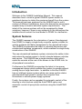
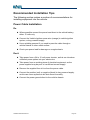
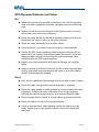
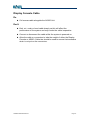
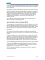
GA8500
INSTALLATION
MANUAL
Version Number:
Part Number:
Issue Date :
1.0 DRAFT
1-1262
March 2008
Copyright Notice
All rights reserved. No part of this publication may be reproduced, stored in a
retrieval system, or transmitted in any form or by any means, electronic,
mechanical photocopying, recording, or otherwise, without the prior written
permission of Rinex Technology.
Disclaimer
No liability is assumed with respect to the use of the information contained
herein. While every precaution has been taken in the preparation of this
publication, RINEX assumes no responsibility for errors or omissions nor is
any liability assumed for damages resulting from the use of the information
contained herein. Further this publication and features described herein are
subject to change without notice.
Use of this system is strictly limited to providing steering assistance to the
operator who must remain in control of the vehicle at all times.
RINEX, including its officers servants and agents, does not make any
representation to any party and will not accept any responsibility or liability
whatsoever for any loss or damage of whatever nature suffered by any such
person or corporation choosing or seeking to use this system or any part
thereof.
By use of this system you agree that RINEX is not liable or responsible for
any damage whatsoever to the vehicle, any property, personal injuries, or
death that may result from the use or abuse of this system.
RINEX LIMITED WARRANTY
RINEX Limited Warranty
Products
This warranty covers all products (the “Products”) manufactured and or sold
by RINEX Technology or their authorised dealers.
RINEX Technology Limited Warranty
RINEX Technology (“RINEX”) hereby warrants solely to the end purchaser of
the Products, subject to the exclusions and procedures set forth herein below,
that the Products sold to such end purchaser shall be free, under normal use
and maintenance, from defects in material and workmanship for a period of 12
months from delivery. Repairs and replacement components are warranted,
subject to the exclusions and procedures set forth below, to be free, under
normal use and maintenance, from defects in material and workmanship for
90 days from delivery, or for the balance of the original warranty period,
whichever is greater.
Purchaser’s Exclusive Remedy
The end purchaser’s exclusive remedy under this warranty shall be limited to
the repair or replacement, at the option of RINEX, of any defective Products
or components thereof. The end user shall notify RINEX or a RINEX
authorised dealer immediately of any claimed defect. Repairs shall be made
through RINEX only.
Exclusions
RINEX does not warrant damage occurring in transit or due to misuse, abuse,
improper installation, neglect, alteration, abnormal use, lightning (or other
electrical discharge), exposure to moisture or dampness, excessive
temperatures, spill of liquids or fluids, or acts of God. Repair, modification or
service of RINEX products by any party other than an authorised RINEX
dealer shall render this warranty null and void. RINEX does not warrant any
Product where the Product serial number or nameplate has been removed,
defaced or altered. RINEX does not warrant claims asserted after the end of
the warranty period.
RINEX does not warrant or guarantee the precision or accuracy of positions
obtained when using Products. The potential accuracy of Products as stated
in RINEX literature and/or Product specifications serves to provide only an
estimate of achievable accuracy based on:
• Specifications provided by the US Department of Defense for GPS
Positioning,
• GPS OEM Receiver specifications of the appropriate manufacturer (if
applicable), and
• DGPS service provider performance specifications.
RINEX reserves the right to modify Products without any obligation to notify,
supply or install any improvements or alterations to existing Products.
GA8500 Installation Manual
Page 1
RINEX LIMITED WARRANTY
No Other Warranties
The foregoing warranty is exclusive of all warranties, whether written, oral,
implied or arising by statute, course of dealing or trade usage, in connection
with the design, sale, installation, service or use of any products or any
components thereof, including, but not limited to, any warranty of
merchantability or fitness for a particular purpose.
Limitation of Liability
The extent of RINEX’S liability for damages of any nature to the end
purchaser or any other person or entity whether in contract or tort and
whether to persons or property shall in no case exceed, in the aggregate, the
cost of correcting the defect in the Product or, at RINEX’S option, the cost of
replacing the defective item. In no event will RINEX be liable for any loss of
production, loss of profits, loss of use for any special, indirect, incidental,
consequential or contingent damages, even if RINEX has been advised of the
possibility of such damages. Without limiting the foregoing, RINEX shall not
be liable for any damages of any kind resulting from installation, use, quality,
performance or accuracy of any products.
Governing Legislation
To the greatest extent possible, this warranty shall be governed by the laws of
the State of Western Australia. In the event that any provision hereof is held
to be invalid by a court of competent jurisdiction, such provision shall be
severed from this warranty and the remaining provisions shall remain in full
force and effect.
Obtaining Warranty Service
In order to obtain warranty service, the end purchaser must bring the Product
to an authorised RINEX dealer along with the end purchaser’s proof of
purchase. The end purchaser must produce the original invoice or other
purchase documents as proof of the purchase date.
The end purchaser is solely responsible for the cost of transportation of the
Product to RINEX or an authorised RINEX dealer and the Product is at the
end purchaser's risk whilst in transit.
For any questions regarding warranty service or to obtain information
regarding the location of any of RINEX’s approved dealers, contact RINEX at
the following address:
Rinex Technology
19 Lyall Street
South Perth
Western Australia 6151
Telephone : (08) 9474 4771
Facsimile :
(08) 9474 4772
Internet : www.rinex.com.au
GA8500 Installation Manual
Page 2
GA8500 Guidance System
Installation Manual
GA8500 Installation Manual
Page 2
Introduction
Welcome to the GA8500 Installation Manual. This manual
describes how to install a typical GA8500 system and/or its
peripheral devices to obtain the maximum benefit from the system.
This manual has been produced for the GA8500 and to suit a
number of different installations, hence the description and images
supplied may not match individual system requirements.. The
intent of the various sections will not be comprised by these
variations, however if there is any ambiguity in the instructions the
installer should contact the local dealer or RINEX for clarification.
System features
The GA8500 represents the culmination of years of development
from RINEX to supply a single body computer system suitable for
vehicle guidance and data management in the agricultural sector.
The GA8500 incorporates the latest in industrial electronics with
miniaturised hardware components, which enables the single body
construction of the GA8500.
The new streamlined hardware system minimises the cable clutter
and makes the system easier to install, relocate between vehicles
and service. The GA8500 has a single interface cable which
exists the console at the rear of the screen to the AS300 Hub, for
all peripheral connections.
Furthermore the GA8500 incorporates the latest in low power
management design which enables the system to operate without
cooling fans or large heat sinks. In addition to this the GA8500
has an intelligent power system which can sense ignition status
and abnormal input power to protect the computer from
fluctuations in vehicle power supply systems.
Finally, the system can be upgraded for automatic control of the
steering in most tractors using the AutoSTEER option and
automatic control of spray boom sections using the AutoSPRAY
option.
GA8500 Installation Manual
Page 3
Safety Precautions
This section describes general safety precautions which should be
observed while installing, servicing and operating the GA8500.
The Safety Symbol will be used in the manual to denote
when precautionary action should be observed for safety
of personnel and equipment. However in all cases users
should be observant of safety when installing or operating
the GA8500.
In all situations during installation and/or maintenance, if the
vehicle is equipped with the GA8500 AutoSTEER option, the
vehicle must remain stationary, switched Off and the AutoSTEER
must be disengaged.
When working on, or a near a vehicle equipped with a GA8500 the
following safety precautions should be observed at all times.
►Be observant of the immediate surroundings.
►Not be under the influence of any substance which may
impair the operator’s judgment.
►Be in control of the vehicle at all times.
►Disengage the AutoSTEER when exiting from the operator's
position.
►Not drive the vehicle on any public property with the system
engaged, or with any part of the system impeding the
operator's vision or normal operation of the vehicle.
►Determine and remain a safe working distance from all
obstacles, including other machinery and people. The
operator is responsible for the safe passage of the vehicle at
all times.
►Ensure that the AutoSTEER system is disengaged prior to
commencing any work on the vehicle.
GA8500 Installation Manual
Page 4
Components
RINEX offer a range of optional items for the GA8500 system and
every effort is made to ensure that this installation manual will
match the equipment supplied. However it is possible that the
equipment supplied may vary slightly from that shown in the
manual. The function of the equipment in question will remain the
same. Should there be any ambiguity with the equipment supplied
the local dealer or RINEX should be contacted to verify the
component and its operation.
Part
Nō.
1-0465
1-0345
1-1460
Component
Description
Illustration
GA8500
console
The console / touch
screen, supplied with
RAM mount ball
attached on rear panel.
Short pigtail cable to
connect with AS300
AS300 hub All peripheral cables
connect to AS300 hub.
The AS300 hub
connects to the
GA8500 console using
a single cable (2.8m
RAM Mount Secures the GA8500 to
the vehicle. RAM
mount allows user to
orientate screen for
optimum viewing angle.
User manual Describes the operation
of the GuideTRAX
and
Addendum software as necessary
to operate the system.
Actual manual varies
with the GA8500
Quick
Describes functions of
reference
typical operations in an
easy to use format.
guide
Actual guide varies with
the GA8500 options
ordered.
GA8500 Installation Manual
Page 5
Part
Nō.
Component
Installation
manual
Description
Illustration
This manual, describes
the typical installation
requirements for the
GA8500 system.
1-2408
12Vdc
Designed to connect
power cable directly to battery or
clean 12Vdc power
source (2.5m long)
1-0055
Installation
kit
Includes cables ties,
tube of silicone sealant,
rubber grommet and
other miscellaneous
components for typical
vehicle installation.
Optional Components
The following list of optional components is available from your
local dealer or RINEX.
Part Nō. Componen
t
1-2406
Description
Illustration
RINEX
Designed to connect
keyed
directly to vehicle
power cable battery and ignition line
of vehicle. Allows
GA8500 system to
GA8500 Installation Manual
Page 6
Installing the System
RINEX recommends that the GA8500 systems be installed by a
local dealer who has knowledge of the system. RINEX can supply
contact information for dealers in different areas that may be able
to supply this service.
The GA8500 system is relatively easy to install and this manual
serves as an installation guide for those people who wish to install
the system themselves.
RINEX recommends that this manual be read thoroughly to
become familiar with all the necessary components before
commencing the installation.
Typical GA8500 in vehicle
Equipment Required
The following equipment will be required to perform the installation
of the GA8500 system into the vehicle. This list not a
comprehensive list of equipment, but rather a guideline of
equipment required.
►Cordless drill
►25mm drill piece or hole saw
►Posi-drive screw bit for drill
►5mm Rat-tail file
►Methylated Spirits and clean rag
GA8500 Installation Manual
Page 7
Installation Time
The GA8500 system may be fitted to a multitude of vehicles and
consequently it is not possible to provide an accurate estimate of
time to install the system. As a rough guide three to fours hours
should be set aside to completely install the system.
Overview
The following diagram is presented as an overview of how all the
components are connected within the system.
GA8500
Console
Vehicle
12Vdc power
AS300 hub
GPS receiver
Remote
Master switch
GA8500 Installation Manual
Page 8
Component Installation
The GA8500 system may be fitted to a multitude of vehicles and
as such it is not possible to provide a set of unique instructions for
individual vehicles. Hence this section recommends where it is
possible to mount the various components of the GA8500 system
and provides examples where applicable.
It is recommended that the components are installed in the
following order for optimal placement of the individual components.
GA8500 Console
The GA8500 console needs to be within easy reach of the
operator when seated in the normal operating position. Ideally it
needs to be easily visible in the forward vision of the operator.
The screen should not be placed where it may impede the
safe vision of the operation of the vehicle.
Typically most agricultural vehicles will have entry to the operators
cab from the left hand side of the vehicle. Consequently most
people prefer to mount the screen on the right hand side of the
vehicle. The screen location should also be such that direct
sunlight on the screen is minimised to avoid intense glare from
sunlight on the screen which makes viewing of the screen difficult.
The screen is fitted with a swivel mount so that it may be easily reorientated in these situations.
Attach the screen mounting arm to the ball mount on the rear of
the screen. The screen may need to be swivelled on its mount for
optimum viewing.
Care must be taken not to drop the screen when unscrewing
the mounting arm, as it is sprung and clamps on to both ball
joints simultaneously. It is recommended that the screen be
laid flat on a clean smooth surface and removed from the
mounting arm before mounting the ball mount and arm on
the vehicle.
Once the desired location has been identified, the remaining ball
mount will need to be secured to the vehicle. It may be necessary
to install a suitable bracket on which to install the ball mount. The
GA8500 Installation Manual
Page 9
ball mount should be firmly secured to the vehicle using either the
supplied self drilling screws.
Use extreme caution whenever drilling holes or attaching any
objects to the vehicle as there may be hidden cables or
hoses. Never drill into the ROP system of any vehicle as this
may damage the integrity of the system. Consult the
vehicle's operating manual prior to drilling any holes.
Once the ball mount is firmly affixed to the vehicle, attach the
mounting arm to it. Place the screen on the mounting arm and
tighten the RAM mount screw on the mounting arm, while holding
the screen securely.
There are optional RAM mounts available from RINEX which
include clamp on brackets, which may simply the installation.
Furthermore there are different length RAM arms available which
once again may simply the individual installation. These can be
ordered from the local dealer or RINEX.
AS300 Hub
The AS300 hub is the connection point for the overall system.
This simplifies the mounting for the GA8500 console as there is
only one cable between the two components. The vehicle
operator will not need to access the AS300 unit, except for
maintenance or cable changes.
The AS300 hub can be mounted in either a vertical, horizontal or
flat plane relative to the vehicle. It should be located inside the
operator's cab and in a relatively "clean and cool" environment,
free of dust.
Typically most AS300 hubs will be mounted either behind the
operator's seat or at the rear of the vehicle. Care should be taken
to ensure that all the connecting cables can be easily attached to
the AS300 hub and that the cable will not be damaged by normal
operation of the vehicle once the AS300 hub is installed.
Prior to installing the AS300 hub the cable lengths to the various
components should be checked for correct length. In particular the
cable to the display console is 3m long, excess cable should be
coiled, and not folded or bunched, which may damage the cable
and cause intermittent operations.
GA8500 Installation Manual
Page 10
The AS300 hub may be secured to the vehicle if required to
minimise disturbance of the cables once installed to the vehicle.
Console cable
The console cable is permanently connected to the AS300 unit.
This multi-core cable connects to the display console at the pigtail
cable connector. The cable will need to be routed inside the
vehicle to avoid crushing, very tight corners, kinks or twists in the
cable.
Attach the display console cable to the pigtail connector at the rear
of the GA8500 console. It will connect only in one position and is a
twist-lock connector. Ensure the cable is secured to the vehicle
using cable ties, to minimise strain on this connector.
DC Power Cable
The DC power cable is 2.5m long and allows the AS300 hub to be
connected directly to the vehicle's 12Vdc power source. The
GA8500 is designed to operate between 9 to 16Vdc, and as such it
will tolerate some fluctuations within a normal vehicles power
system. The DC power cable is terminated with bootlace ferrules
to suit a variety of installations such as screw terminals.
Connect the DC power cable to the vehicle’s power supply. The
red wire is to be connected to 12Vdc positive and the black wire to
the vehicles earth.
Then route the cable to the AS300 hub ensuring that the cable will
not be crushed or damaged in any part of the installation.
Connect the DC power cable to the power connector port on the
AS300 hub. The GA8550 will emit two short beeps indicating that
DC power has been connected to the system.
The GA8500 should only be started once the vehicle engine
is running. This will minimise power spikes to the system
which may cause damage to the GA8500 console or AS300
hub.
The GA8500 is a 12Vdc (negative-to-earth) system only.
Connecting to 24V dc or a positive-to-earth system will cause
GA8500 Installation Manual
Page 11
damage which is not covered by warranty. Do not connect to
only one battery of a 24V dc system as this may cause
damage to vehicle batteries and/or connected equipment.
The GA8500 may also be powered to the vehicle’s ignition circuit
so that the system will automatically start once the vehicle has
been started. An optional DC power cable can be installed with an
ignition sense – line that will enable this feature.
There are optional power cables available from RINEX, including
the universal circular connector found in many tractors as well as
the John Deere power strip style. The use of these optional power
cables will simply the installation.
GPS receiver
The GA8500 is compatible with most GPS receivers and as such
specific installation notes for each GPS receiver is not provided.
In virtually all situations the GPS receiver is to be connected to
Port B on the AS300 hub. The GA8500 is configured to receive
GPS information at 19,200 baud (serial interface protocol is 8,N,1).
Remote master switch
The GA8500 is designed to sense 12Vdc on remote master
switches, which will activate the treatment recording function on
the GA8500. This feature is described in the GuideTRAX user
manual addendum.
This remote master switch allows the user to connect an external
switch to the system, to turn On and Off the recording mode of the
guidance software, without the need to touch the screen icon.
1) Connect one side of the switch to +12VDC. Connect the
other side of the switch to the Remote Master connector in
the AS300 hub
2) Follow the instructions in the GuideTRAX User Manual
Addendum for instructions on configuring the system
software to recognise the switch.
3) The system will start recording when the switch contacts are
closed, and stop when the switch contacts are open.
GA8500 Installation Manual
Page 12
Remote Input button
The Remote Input allows the user to connect an external
momentary push-button to the system, to carry out simple
operations, such as turning guidance on or off.
To connect a push-button to the AS300 for use as a remote input:
1) Connect one side of the button to +12VDC. Connect the
other side of the button to the Remote Input connector in
the AS300 hub.
2) Follow the instructions in the GuideTRAX User Manual
Addendum for instructions on configuring the system
software to recognise the button.
3) The assigned function will activate when the button is
pressed.
GA8500 Installation Manual
Page 13
System Operation
Once the GA8500 Guidance system and its basic components
have been installed and the console cable has been connected it
is almost ready to start the system for the first time. Prior to
starting there are some basic checks which should be observed.
Ensure that the all necessary components are installed in
accordance with this and other respective manual.
After completing the above checks, start the vehicle.
After a few minutes during which the system performs some selfchecks and loads software, the GA8500 will start, displaying the
Main Screen consisting of the Virtual Road Window, the Map
Screen, Menu buttons and GPS Status Icon (see the user manual
for more information). It may take up to half an hour for the GPS
receiver/antenna to become fully operational. The GPS
receiver/antenna is fully operational when the GPS Status Icon in
the bottom right hand corner of the screen changes to the scrolling
satellite:
Further options for starting up and shutting down the system are
contained in the Addendum to the User Manual.
GA8500 Installation Manual
Page 14
Recommended Installation Tips
The following section makes a number of recommendations for
installing equipment into the vehicle.
Power Cable Installation
Do
► Where possible connect the power lead direct to the vehicle battery,
either 12 volts only.
► Connect the Vehicle Ignition sense wire (orange) to vehicle ignition
system, or key powered supply.
► Use a suitable grommet if you need to pass the cable through a
vehicle firewall or other metal surface.
► Check your power lead for damage on a regular basis.
Don’t
► Take power from a 24 to 12 volt power inverter, as this can introduce
unfiltered power spikes into your electronics.
► Take power from an existing piece of electrical equipment, as the
power supplied may be poor or insufficient current supply.
► Remove the supplied fuse in line from the power cable.
► Connect the positive (red) or negative (black) to key powered supply
as this can cause systems to be shut down incorrectly.
► Connect the power ground direct to the vehicle chassis.
GA8500 Installation Manual
Page 15
GPS Receiver/Antenna and Cable
Do
► Install the receiver/antenna where possible on the vehicle centerline,
clear from other equipment antennas, spotlights and air-conditioning
units.
► Make sure that the receiver/antenna is the highest point on the roof
with a clear view of the surrounding sky.
► Route the cable with as few bends as possible, making sure that all
bends have as large a radius as the route will allow.
► Route the cable separately from all other cables.
► Use a grommet if you need to pass through any metal surfaces.
► Secure the GPS receiver/antenna cable at regular intervals (30 cm
approx) with the supplied self adhesive cable tie mounts. Loose and
flapping cables can induce noise into the receiver/antenna cable
interfering with the GPS signal reception.
► Inspect your receiver/antenna and cable for damage on a regular
basis.
► Make sure there is sufficient clearance for the receiver/antenna when
driving underneath overhead power lines, trees or any other objects
which could damage the antenna.
Don’t
► Kink, crush or bend the cable sharply as this can lead to loss of signal.
► Route the cable through either vehicle doorways or windows.
► Route the cable parallel to existing power or antenna leads from other
equipment. If they must cross each other do so at right angles to
minimise the risk of induced noise on your receiver/antenna cable.
► Route through vehicle firewall or similar without grommet protection.
► Place any objects on top of the receiver/antenna.
► Leave antenna/receiver cable flapping outside the cab as this can
cause interference to your signal reception. Secure the cable with
cable ties.
GA8500 Installation Manual
Page 16
Display Console Cable
Do
► Coil excess cable alongside the AS300 Unit.
Don't
► Kink, cut, crush or bend cable sharply as this will affect the
performance of the system and may render the cable inoperative.
► Connect or disconnect the cable whilst the system is powered on.
► Allow the cable or connectors to take the weight of either the Display
Console or AS300. Cable ties should be used to ensure that excessive
strain is not put on the connectors.
GA8500 Installation Manual
Page 17
Optional Peripheral Installation Notes
RINEX DC power cable with ignition sense
The RINEX DC power cable is 7m long and allows the AS300 hub
to be connected directly to the vehicle's battery and an ignition line.
The RINEX power cable should not be connected directly to
the battery if the vehicle is equipped with battery isolator
switch. In these cases the negative wire (black) should be
connected to the vehicle/chassis side of the isolator.
The GA8500 is a 12V DC (negative-to-earth) system only.
Connecting to 24V or a positive-to-earth system will cause
damage which is not covered by warranty.
Do not connect to only one battery of a 24V DC system. This
can cause damage to vehicle batteries and/or connected
equipment.
►
AS300 hub termination
The 4 pin plastic circular connector connects to the AS300.
►
Vehicle battery termination
Red (positive) wire with in-line fuse connects to the vehicle
battery positive terminal
Black (negative) wire connects to the vehicle battery negative
terminal.
Orange wire connects to the vehicle ignition ON circuit.
The power cable supplied should only be connected directly to
the battery with the supplied fuse in place. We strongly
recommend NOT removing the supplied fuse. If a power wire
should short to the vehicle body, a battery can supply a
current that will heat the wire to the point where the insulation
will catch fire. A fuse mounted inline near the battery
connection point and before the cable passes through the
vehicle panel will prevent the risk of a vehicle fire.
GA8500 Installation Manual
Page 18
In all cases when connecting the RINEX power cable to the vehicle
if you are unsure of the connections you should consult a qualified
auto-electrician.
The cable should be routed from the operator's cab to the vehicle's
batteries through a dedicated cable gland if supplied. If necessary
an exit hole will have to be drilled into the vehicle which should be
fitted with a rubber grommet to protect the cable from rubbing
directly on the vehicle wall. The hole should be sealed with the
supplied silicone sealant to prevent dust and moisture from
entering the cab.
Two leads have been fitted with M12 (12mm) ring terminals to
allow connection to the battery posts.
Vehicle Ignition Sense (Orange Wire)
The orange wire is connected into the vehicle's ignition circuit such
that the GA8500 will detect when the ignition is switched on and
off. The Rinex power cable is assembled within split tubing to allow
the orange wire to be separated at any point to allow for in-cab
termination.
This connection should be made by a qualified auto-electrician.
However, as a short term solution, the connection can be made as
follows:
Locate an ignition wire on the vehicle that is on when the vehicle
ignition is on. Use the Scotch-Lok connector provided to splice into
the wire. The orange wire is fitted with a male push-on connector
which fits directly into the Scotch Lok connector provided. It is
recommended that cable ties are used to secure any free cables.
Once the RINEX power cable has been connected to the terminals
of the vehicle's battery and routed through the vehicle it may be
connected the AS300. The display Console will sound two short
beeps when it is connected to 12V DC power.
DO NOT switch the Display Console on at this time. Leave the
vehicle ignition OFF.
GA8500 Installation Manual
Page 19