1
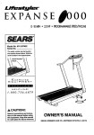
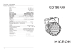
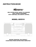
%
A
N S E
750
Model No. 831.297491
Serial No.
The serialnumbercanbe foundin the
locationshownbelow. Writethesedal
numberin thespaceabove.
Serial Number
De_
EOU
[_RIl
I PM
_n.!
n
ENT
R*|_
i_
1
HELPLINE!
1-800-735-5879
USER'S MANUAL
SEARS, ROEBUCK AND CO., HOFFMAN ESTATES, IL 60179
FULL 90 DAY WARRANTY
For 90 days from the date of purchase, if failure occurs due to defect in material or workmanship in this
SEARS TREADMILL EXERCISER, contact the nearest SEARS service centers throughout the United
States and SEARS will repair or replace the TREADMILL EXERCISER, free of charge.
This warranty does not apply when the TREADMILL EXERCISER is used commercially or for rental purposes.
This warranty gives you specific legal rights, and you may also have other rights which vary from state
to state.
SEARS, ROEBUCK AND CO., DEP_,
2
HOFFMAN ESTATES, IL 60179
I
AN
S E
750
TABLE OF CONTENTS
IMPORTANT PRECAUTIONS .................................................................
BEFORE YOU BEGIN .......................................................................
ASSEMBLY ...............................................................................
OPERATION AND ADJUSTMENT .............................................................
TROUBLE-SHOOTING AND STORAGE ........................................................
CONDITIONING GUIDELINES ...............
. ...............................................
ORDERING REPLACEMENT PARTS ..................................................
4
5
6
7
11
13
Back Cover
Note: An EXPLODED DRAWING and a PART LIST are attached to the center of this manual. S_;vethe
EXPLODED DRAWING and PART LIST for future reference.
3
4
BEFORE YOU BEGIN
Thank you for selecting the SEARS LIFESTYLEFP EXPANSE 750 treadmill. The EXPANSE 750 treadmill
blends advanced technology with innovative d_=signto
let you enjoy an excellent form of cardiovascular exercise in the convenience and privacy of your home.
For your benefit, read this manual carefully before
using the treadmill. If you have additional questions,
please call our toll-free HELPLINE at 1-800-736-6879,
Monday through Saturday, 7 a.m. until 7 p.m. Central
Time (excluding holidays). To help us assist you,
please note the product model number and serial number before calling. The model number of the treadmill
is 831.297491. The sedal number can be found on a
decal attached to the treadmill (see the front cover of
this manual for the location).
Before reading further, please review the drawing
below and familiarize yourself with the parts that are
labeled.
Beverage
Speed Control
(Water bottle
Belt
Circuit Breaker
Foot RailsI
On/Off
Padded Walking Platform
for maximum comfort
FRONT
RIGHT SIDE
Incline Leg
BACK
Rear Roller
Adjustment Bolt
Power Cord
Incline Leg Foot
5
A SE VIBLY
Assembly requires two people. Set the treadmill in a cleared area and remove all packing materials. Do not dispose of the packing materials until assembly is completed. Refsr to ths drawings below to identify the small parts
used i;_a_.sembly. Assembly can be completed using the inc!uded 7/32" allen wrench _.
©
Updght Spacer (66)-2
Star Washer (22)-2
Flange Nut (24)-4
3/8" Washer (58)-4
_.\
.
\
\
\
\
\
\
\\
\
\
\
\
\
\
\
\
\
\
\
\ \\\\\\
3/8" x 1" Console Bolt (2)-4
_IIL j
Hold an Upright Spacer (66) inside the lower end of one of the
Uprights (11). Insert a 3/8" x 3 112"Bolt (65), with a 3/8"
Washer (58), into the lower hole in the Upright and through the
Updght Spacer. Slide a Star Washer (22) onto the Bolt. Insert'a
3/8" x 3 112"Bolt (65), with a 3/8" Washer (58), through the
other hole near the lower end of the Updght.
Insert the 3/8" x 3 112"Bolts (65) into the indicated holes in the
Frame (57). Reach under the Frame and loosely thread a
Flange Nut (24) onto each Bolt.
22
I
Attach the other Upright (11) to the left side of the Frame (57)
in the same manner.
.
Hold the Console (7) near the upper end of the right Upright
(11). Feed the Long Wire Harness (12) down into the Upright,
until the Long Wire Harness extends from the lower end of the
Upright. Note: If the end of the Long Wire Harness gets caught
in the Upright, it may be helpful to turn the 3/8" x 3 112"Bolts
(65) back and forth. Be careful not to damage the Long Wire
Harness. Make sure that the Cable Looms (13) are in the
upper and lower ends of the Upright.
If there are cable ties in the holes in the Console Plate (4), cut
them. Insert the Console Plate into the right Upright (11) and
the left Upright (not shown). Attach each side of the Console
Plate with two 3/8" x 1"Console Bolts (2).
Tighten the four 3/8" x 3 112"Bolts (65).
Plug the lower end of the Long Wire Harness (12) into the
Short Wire Harness (51). The small latch on the Long Wire
Harness should snap onto the Short Wire Harness (see the
inset drawing). If the Wire Harnesses do not fit together easily,
turn them; do not force the Wire Harnesses together. Slide the
end of the Cable Loom (13) against the end of the Long Wire
Harness. Be careful not to damage the Wire Harnesses.
24
66---"_
2
7
3. Remove the paper backing from the Wrench Clip (30). Press
the Wrench Clip onto the Frame (57) in the indicated location.
Press the 3/16" Allen Wrench (77) into the Wrench Clip,
3
Make sure that the two Incline Leg Feet (72) are turned so the
flat sides are at the bottom.
Make sure that all pads are tightened before using the treadmill.
Note: Cover the floor beneath the treadmill to protect the
floor or carpel
OPERATION AND ADJUSTMENT
THE PERFORMANT LUBE TM WALKING BELT
Grounded
Your treadmill features a low-maintenance walking belt
coated with PERFORMANT LUBE TM, a high-performance lubricant. During the first few hours of use, a
small amount of white powder may accumulate on the
foot rails and the walking platform. The white powder is
high-performance lubricant from the walking bell Never
apply sUlcone spray or other substances to the walkIng belt or the walking platform. They will deteriorate
the walking belt and cause excessive wear.
Grounding Plug
Grounding Pin
HOW TO PLUG IN THE POWER CORD
This product must be grounded. If it should malfunction or break down, grounding provides a path of least
resistance for alectdc current to reduce the Ask of elec-
Grounded Outlet
2
Grounded
Box
tric shock. This product is equipped with a cord having
an equipment-grounding conductor and a grounding
plug. Plug the power cord into an appropriate outlet that Is properly installed and grounded in accordance with all local codes and ordinances.
Grounding Pin
Grounding
Plug
Lug
Metal Screw
The temporary adapter should be used only until a propedy grounded outlet (drawing 1) can be installedby a
qualified electrician.
This product is for use on a nominal 120-volt circuit,and
has a groundingplug that looks like the plug illustratedin
drawing 1 on this page. A temporary adapter that looks
like the adapter illustratedin drawing 2 may be used to
connect this plug to a 2-pele receptacle as shown in
drawing 2 if a propedygrounded outlet is not available.
The green-colored rigid ear, lug, or the like extending
from the adapter must be connected to a permanent
ground such as a properly grounded outlet box cover.
Whenever the adapter is used it must be held in place
by a metal screw. Some 2-pole receptacle outlet, box
covers are not grounded. Contaet-a-quelified electrician to determine if the outlet box cover is
grounded before using an adapter.
7
DIAGRAM
OF THE CONSOLE
Mod_
III
II
START
/STOP
\
_Note:
If there is a thin sheet
of clear plastic on the face of
the console, remove it.
TO PLUG IN THE POWER CORD on page 7).
Next, step onto the foot rails of the treadmill. Find the
clip attached to the SAFEKEY (see the drawing above),
and slide the clip onto the waistband of your clothing.
Follow the steps below to operate the console:
H
Insert the SAFEKEY fully Into the power switch,
is inserted, the four
displays and the
green MANUAL
mode indicator will
_
_]
light.
STEP BY STEP CONSOLE OPERATION
The treadmill console features a manual mode and four
preset workout programs. In the manual mode, the
speed of the walking belt can be changed with the electronic speed control. When one of the workout programs
is selected, the console will automatically control the
speed as it guides you through an effective workout.
Before operating the
console, make sure
that the on/off switch
near the power cord
is in the "on" position.
8
Position
If the SAFEKEY is in the console, remove it. Make sure
that the power cord is properly plugged in. (See HOW
B
Reset the speed control and select a speed
setting.
Slide the speed control down to
the "RESET" position. Note:
Each time the walking belt Is
stopped, the speed control
must be moved to the
"RESET" position before the
walking belt can be restarted,
I
,.,-.4
II
i;
Next, slide the speed control
upward to select a speed setting. Note: If the SAFEKEY
was Just Inserted, or If the
RE$.='r/
walking belt was stopped
with the START/STOP button,
the walking belt will not begin to move yet.
i I'Ll"
Press the SELECT MODE button to select the
desired mode.
When the SAFEKEY is inserted, the console will be
in the MANUAL mode.
If you want to select
one of the four preset programs, press
the SELECT MODE
button. The red
PROGRAM A indicator will light. To select PROGRAM B, C, or D, repeatedly press the SELECT MODE button.
Note: PROGRAMS A and B are twenty-minute programs; PROGRAMS C and D are thirty-minute programs. The speed profiles in the center of the console show how the speed of the walking belt will
change during the programs. During PROGRAM A,
for example, the speed will gradually increase during the first ten minutes, and then gradually decrease during the last ten minutes. Each program
will begin with a two-minute warm-up period, and
end with a two-minute cool-down period.
D
Press the START/STOP button.
START/STOP button
is pressed, the walking belt will begin to
move. Hold the
handrails and care-
PII
fully begin walking on the walking belt.
If the console is in the manual mode, change the
speed of the walking belt as desired by sliding
the speed control. To stop the walking belt, slide the
speed control to the "RESET" position.
If one of the preset progrems is selected, the speed
setting you selected will be the minimum speed setting for the program. The speed of the walking belt
will then change automatically during the program as
shown by the speed profilesin the center of the console. When the program is completed, the walking
belt will automatically slow to a stop. Note: If the intensity level of the program is too easy or too difficult,
adjust the speed controlto select a new minimum
speed setting. To stop the program temporarily,slide
the speed controlto the "RESET" position. To restart
the program, slide the speed control up to the desired
position.To terminate the progrem before the program is completed, press the START/STOP button.
[_'_ Follow your progress with the monitor displays.
The four monitor displays PrOVideinstant feedback:
• CAL/FAT CAL display--Displays the
approximate numbers of Calories
and Fat Calories
you have burned
(see BURNING FAT on page 13). Every sevan
seconds, the display will change from one number
to the other (an =F" will appear when the number
of Fat Calories is shown). Note: The actual number of Calories you have burned may differ slightly
from the number shown if the speed or incline is
near the lowest or highest setting.
When the console
is in the manual
mode,display-the elapsed
• TIME
time will be shown.
When one of the
_
_
_
I
preset programs is
selected, the time remaining in the program will be
displayed.
• SPEED display-Displays the speed
of the walking belt,
in miles per hour
(MPH) or kilometers per hour
(KPH).
Note: To change
the unit of measurement, hold
down the
START/STOP button while inserting
the SAFEKEY into
the console. An "E" (for English system--miles per
hour) or "M" (for Metric system--kilometers per
hour) will appear in the DISTANCE display. Press
the SELECT MODE button to select the desired
setting. Remove and then reinsert the SAFEKEY.
An MPH or a KPH will appear in the SPEED display to show which unit of measurement you have
selected.
• DISTANCE-Displays the distance that you
have walked or
run. If an MPH appears in the
SPEED display,
the distance will be displayed in miles. If a KPH
appears, the distance will be displayed in kilometers.
9
_
Change the incline of the treadmill, if desired.
To vary the intensity
of your workout, the
incline of the treadmill can be changed.
To change the incline, hold down one
of the Incline buttons
until the desired incline is reached.
10
[]
When you are finished, remove the SAFEKEY.
When you are finished exercising,
step onto the foot
rails and remove
the SAFEKEY from
the console, Store
the SAFEKEY in a
secure location.
I
TROUBLE-SHOOTING
AND STORAGE
Most treadmill problems can be solved by followlng the simple steps below. Find the symptom that applies, and follow the steps listed. If further assistance Is needed, call our toll-free HELPLINE at 1-800-7366879, Monday through Saturday, 7 a.m. until 7 p.m. Central Time (excluding holidays).
1. SYMPTOM: THE POWER DOES NOT TURN ON
a. Make sure that the power.cord is plugged into a properly grounded outlet. (See HOW TO PLUG IN THE
POWER CORD on page 7.) If an extension cord is needed, use only a 14-gauge general-purpose cord of
five feet or less In length.
b. After the power cord has been plugged in, make sure that the SAFEKEY is fully inserted into the console.
Various indicators on the console should lighL (See step 1 page 8.)
c. Check the circuit breaker located on the treadmill near the
power cord. If the switch protrudes as shown, the circuit
breaker has tripped. To reset the circuit breaker, wait for five
minutes and then press the switch back in.
Tdpped
d. Check the on/off switch located at the front of the treadmill
near the power cord. The switch must be in the =on" position.
=On"
Position
2. SYMPTOM: THE POWER TURNS OFF DURING USE
a. Check the cimutt breaker located on the treadmill frame near the power cord. If the circuit breaker has
tdpped (see the drawing above), wait for five minutes and then press the switch back in.
b. Make sure that the power cord is plugged in.
c. Removethe SAFEKEYfrom the console.ReinserttheSAFEKEYfully intothe console.(See step 1 on page
8.)
d. Check to make sure the on/off switch is in the =on" position. (See 1. d. above.)
e. If the treadmill stiii will not run, please call our toll-free HELPLINE.
3. SYMPTOM: THE WALKING BELT SLOWS WHEN WALKED ON
a. If an extension cord is needed, use only a 14-gauge general-purpose cord of five feet or less in length.
b. If the walking belt still slows when walked on, please call our toll-free HELPLINE.
4, SYMPTOM: THE WALKING BELT IS OFF-CENTER OR SLIPS WHEN WALKED ON
a. if the walking belt has shifted to the left, first remove the
SAFEKEY and UNPLUG THE POWER CORD. Using the 3/16"
allen wrench, turn the left rear roller adjustment bolt clockwise
114 of a tum. Plug in the power cord, insert the SAFEKEY and
run the treadmill for a few minutes. Repeat until the walking belt
is centered.
a
11
b. iF !he w_-i'.,;ingbelt h_s shi!_mdto the right, first remove the
SAFEKEY and UNPLUG THE POWER CORD. Using the 3/16"
allen wrench, tum the left rear roller adjustment bolt counterclockwise 1/4 of a turn. Plug in the power cord, insert the
SAFEKEY and run the treadmill for a few minutes. Repeat until
tha walking belt is centered.
b
MAINTENANCE
The treadmill can be wiped clean with a damp cloth. Remove the beverage holder Insert for easy cleaning. Be sure to press the beverage
holder Insert completely into the console after cleaning.
Beverage
Holder Insert
STORAGE
Unplug the power cord when the treadmill is not in use.
:Remove the indicated bolt, washer, and nut from the Iowel' end of
each updghL Loosen the other bolt and lower the upright. Keep all
- h_rdware in a secure location.
: I_s recommended that the treadmill be covered during extended pe:ri_s of storage.
Loosen
12
Remove
CONDITIONING GUIDELINES
Training Zone (Beats/Min.)
The following guidelines will help you to plan your exemise program. Remember--these are general guidelines. For more detailed information about exercise,
obtain a reputable book or consult your physician.
EXERCISE INTENSITY
Whether you want to bum fat, strengthen your cardiovascular system, or increase your athletic performance, you can tailor your exercise to your specific
goals. The key to achieving the desired results is to exercise with the proper intensity.
Burning Fat
To bum fat effectively, you must exercise at a relatively
low intensity level for a sustained period of time.
Dudng the first few minutes of exercise, your body
uses easily accessible carbohydrate calories for energy. Only after the first few minutes of exercise does
your body begin to use stored fat calories for energy.
If your goal is to bum fat, set the speed control on the
console to FAT BURN to help you maintain the proper
intensity level. (See pages 8 and 9.)
Age
Unconditioned
Conditioned
20
138-167
133-162
25
136-166
132-160
30
135-164
130-158
35
134-162
129-156
40
132-161
127-155
45
131-159
125-153
80
129-156
124-150
55
127-155
122-149
60
126-153
121-147
65
125-151
119-145
70
123-150
118-144
75
122-147
117-142
80
120,-146
115-140
85
118-144
114.139
To measure your heart rate, stop exercising and place
two fingers on your wrist as shown below. Take a six-
Aerobic Exercise
If your goal is to strengthen your cardiovascular system, your exercise must be =aerobic." Aerobic exercise
is activity that requires large amounts of oxygen for
prolonged periods of time. This increases the demand
on the heart to pump blood to the muscles, and on the
lungs to oxygenate the blood. The proper intensity
level for aerobic exercise can be found by using your
heart rate as a guide. As you exemise, your heart rate
should be kept at a level between 70% and 85% of
your maximum possible heart rate. This is known as
your "training zone." You can find your training zone in
the table at the top of this page. Training zones are
listed according to age and physical condition.
During the first few months of your exercise program,
keep your heart rate near the low end of your training
zone as you exercise. After a few months of regular
exercise, your heart rate can be gradually increased
until it is near the middle of your training zone as you
exercise.
second heartbeat count, and multiply the result by ten
to find your heart rate. (A six-second count is used because your heart rate drops quickly when you stop exercising.) If your heart rate is too high or too low, adjust
the intensity of your exercise.
It may also be helpful to set the speed control on the
console to AEROBIC to help you maintain the proper
intensity level. (See pages 8 and 9.)
Performance Training
If your goal is high performance athletic conditioning,
set the speed control on the console to PERFORMANCE to help you maintain the proper intensity level.
(See pages 8 and 9.)
13
WORKOUT GUIDELI;'_SS
WORKOUT ATRRE
Each workout should include three basic parts: (1) a
warm-up, (2) training zone exercise, and (3) a cooldown.
Exemise clothing should be comfortable and allow unrestricted movement. Do not wear rubberized or plastic
clothing that can interfere with the evaporation of
sweat from your skin. Always wear athletic shoes that
are flexible and provide good protection and support.
Warm-up
Warming up prepares the body for exercise by increasing cimulation, dalivedng more oxygen to the muscles
and raising the body temperature. Begin each workout
with 5 to 10 minutes of stretching and light exemise to
warm up (see SUGGESTED STRETCHES on page 15).
Tralnlng Zone Exercise
After warming up, increase the intensity of your exercise until your pulse is In your training zone for 20 to
60 minutes. (During the first few weeks of your exercise program, do not keep your pulse in your training
zone for longer than 20 minutes.) Breathe regularly
and deeply as you exemise--never hold your breath.
Cool-down
Finish each workout with 5 to 10 minutes of activity
similar to that of.the warm-up phase, Thorough stretching offsets muscle contractions and other problems
caused when you stop exercising suddenly. Stretching
for increased flexibility is often most effective dudng
this phase. This phase should leave you relaxed and
comfortably tired.
Instead of waiting for a convenient time to exercise,
plan a specific time. The morning hours work well for
many, and the self-discipline required to rise early and
exercise often carries through the day to help increase
productivity in other areas. For some, exemising before dinner initiates a period of winding down from the
day's activities. Whatever time you choose, be consistent and stick with it.
To maintain or improve your condition, complete three
workouts each week, with at least one day of rest between workouts. After a few months of regular exercise, you may complete up to five workouts each
week, if desired. Remember, the key to suCcess is to
make exercise a regular and enjoyable part of your
everyday life.
14
ADDITIONAL SUGGESTIONS
Creating a more active lifestyle, In addition to establishing a regular exercise program, will help you to
achieve your fitness goals.
It's easy to improve your lifestyle by making a few
changes In your daily routine:
Keep yourself moving throughout the day. Use the
stairs instead of the elevator. Park a half mile away
from work or get off the bus a couple of blocks before
your stop and walk the remaining distance.
Increase midday productivity, creativity and energy by
replacing a heavy lunch with a light meal. Spend the
extra time in physical activity such as walking.
Substitute manually-operated devices for automatic
equipment such as lawn-cara machinery, power tools
and snow removers.
Stop smoking; smoking nearly doubles the dsk of coronary heart disease. (Framington Heart Study)
Reduce or eliminate alcohol consumption. Alcohol is a
major cause of liver problems and other health disorders. (Office of Disease Prevention and Health
Promotion)
Reduce your intake of fat. Less than 30% of the calories you consume each day should come from fat.
Excessive fat consumption has been linked to numerous causes of death, including heart disease and cancer.
Know and keep a record of your cholesterol level,
blood pressure and other health information. Keep
your blood pressure below 140/90; keeping it below
125/85 is preferable.
SUGGESTED STRETCHES
The following stretches can provide a good warm-up or cool-down. Correct form for each stretch is shown in the
drawings below. Move slowly as you stretch--never bounce.
TOE TOUCH STRETCH
Stand with your knees bent slightly and slowly bend forward
from your hips. Allow your back and shoulders to relax as you
reach down toward your toes as far as possible. Hold for 15
counts, then relax. Repeat 3 times.
Stretches: Hamstrings, back of knees and back.
HAMSTRING STRETCH
Sit with one leg extended. Bring the sole of the opposite foot toward you and rest it against the inner thigh of your extended
leg. Reach toward your toes as far as possible. Hold for 15
counts, then relax. Repeat 3 times for both legs.
Stretches: Hamstrings, lower back and groin.
CALF/ACHILLES STRETCH
With one leg in front of the other, reach forward and place your
hands against a wall. Keep your back leg straight and your
back foot flat on the floor. Bend your front leg, lean forward and
move your hips toward the wall. Hold for 15 counts, then relax.
Repeat 3 times for both legs. To cause further stretching of the
achilles tendons, bend your back leg as well.
Stretches: Calves, achilles tendons and ankles.
QUADRICEPS STRETCH
With one hand against a wall for balance, reach back and grasp
one foot with your other hand. Bdng your heel as close to your
buttocks as possible. Hold for 15 counts, then relax. Repeat 3
times for both legs.
Stretches: Quadriceps and hip muscles.
INNER THIGH STRETCH
Sit with the soles of your feet together and your knees outward.
Pull your feet toward your groin area as far as possible. Hold
for 15 counts, then relax. Repeat 3 times.
Stretches: Quadriceps and hip muscles.
15
REP,-JIOVE
THIS PART LIST/EXPLODED
DRAWING FROM THE MANUALt
EXPLODED DRAWING--Model
No. 831.297491
R99sc
7
3
2
8
6
56
16
6
9
12
58
65
66 _
30
22
95 (
78
77
o.o
75
46
72
60
74
6o..-_
95
23
I
32
2
44
55
58
64
52
"%_---,
52
65
70
31
56
PART LIST--Model
No. 831.297491
Key
No.
Part
No.
Qty.
1
2
119038
013438
1
4
3
4
5
6
7
8
9
10
125150
126133
126075
013322
127003
125077
111430
016057
1
1
1
20
1
1
4
7
11
12
13
i '_14
• 15
125864
126775
113204
105477
124100
2
1
2
2
1
Updght
Long Wire Hamess
Cable Loom
Motor Nut
Motor
16
17
18
19
20
21
112825
126134
012108
013547
122812
100994
1
1
1
1
1
2
Pulley/Flywheel/Fan
Belt
Motor Pivot Nut
Motor Tension Bolt
Motor Tension Washer
Motor Bolt
23
24
25
26
014117
125757
120867
120785
107503
3
1
5
1
1
Star Washer
Front Hood
Range Nut
Motor Mount Bracket
Motor Swivel Bolt
27
28
123470
117882
1
1
Spring Sleeve
Reed Switch/Wire
29
30
31
32
33
34
35
36
37
38
39
40
41
42
43
44
45
46
47
48
100498
016026
120630
054023
127352
126111
125819
016029
126046
013300
127420
119163
127202
112609
014127
124669
124695
117806
123647
013162
1
1
15
3
1
1
4
4
1
8
8
1
1
1
5
1
1
4
1
8
Magnet
Wrench Clip
Screw
Wire Clip
Controller
Power Board
Plastic Stand-Off
4" Wire Tie
Electronics Bracket
Anchor Screw
Hood Anchor
On/Off Switch
Circuit Breaker
Front Roller Adj. Bolt
Adjustment Washer
Power Cord
Grommet
Wheel Bolt
Wheel
Safety Cover Screw
Description
SAFEKEY_/CLIP
3/8" x 1" Console Bolt
Beverage Insert
Console Plate
Console Tray .
Console Screw
Console
Beverage Holder
Cage Nut
8" Cable Tie
R9950
Key
No.
Part
No.
49
50
51
52
58
54
55
56
57
58
59
60
61
62
127203
012056
126457
112669
120647
127005
127007
045017
NSP
010432
013544
012149
125855
013375
1
4
1
2
1
1
1 •
1
1
4
2
4
1
1
Safety Cover
Wheel Nut
Short Wire Harness
Incline Pin
Front RolledPullsy
Walking Platform
Walking Belt
7/32" Allen Wrench
Frame
3/8" Washer
Incline Leg Bolt
Incline Nut
Incline Rod
Incline Bolt
63
64
65
66
67
68
69
70
71
72
73
74
75
76
77
78
79
80
81
82
83
84
85
#
#
#
#
#
#
#
#
116927
114270
123494
122332
109365
127098
125871
126058
106334
125861
127544
125774
126136
105444
126040
125758
127566
100691
125860
127009
123469
119439
116586
107507
124770
114963
124785
124761
109407
102634
127565
1
1
4
2
1
1
1
1
2
2
1
1
1
1
1
1
2
8
1
1
1
1
8
1
1
1
1
1
1
1
1
Tie Holder Clamp
Incline Spacer
3/8" x 3 112' Bolt
Upright Spacer
Choke
Belt Guide
Motor Controller Wire
Incline Motor
Cotter Pin
Incline Leg Foot
Rear Guard Spring
Incline Leg
Right Rear Adjustment Bolt
Left Rear Adjustment Bolt
3/16" Allen Wrench
Rear Hood
Foot Rail
Platform Screw
Rear Roller Guard
Rear Roller
Rear Roller Tension Spring
Rear Roller Tension Nut
Hood Screw
14" White Wire, Male/Female
8" White Wire, Male/Female
8" White Wire, 2 Female
14" Blue Wire, 2 Female
8" Blue Wire, 2 Female
4" Black Wire, 2 Female
8" Green Ground Wire
User's Manual
Qty.
Description
--=
Note: "#" indicates a non-illustrated part.
=
|
;EARS
Model No. 831.297491
The model number and serial number of your SEARS
LIFESTYLEFP EXPANSE 750 treadmill are listed on a decal attached to the frame. See the front cover of this manual to find the location of the decal.
QUESTIONS?
All replacement parts are available for immediate purchase or
special order when you visit your nearest SEARS Service Center.
To request servlca or to order parts by telephone, call the toll-free
numbers listed at the left.
If you find that:
• you need help assembling or
_ oparatlng the LIFESTYLEFP
EXPANSE 750
"._':- a part is missing
i :'_• oryou need to schedule repair
service
%,
_call
our toll-free HELPLINE
When requesting help or service, or ordering parts, please be prepared to provide the following information:
• The NAME OF THE PRODUCT (SEARS LIFESTYLEPP EXPANSE 750)
• The MODEL NUMBER OF THE PRODUCT (831.297491)
• The PART NUMBER OF THE PART (see the EXPLODED
DRAWING and PART LIST attached to the center of this manual)
!.-800-736-6879
_!_Monday-Saturday,
7 am-7 pm
_entral
Time (excluding holidays)
• The DESCRIPTION OF THE PART (see the EXPLODED DRAWING and PART LIST attached to the center of this manual)
REPLACEMENT
PARTS
If parts become worn and need
to be replaced, call the following
toll-free number
1-800-FON-PART
(1-800-366-7278)
SEARS, ROEBUCK AND CO, HOFFMAN ESTATES, IL 60179 USA
Part No. 127565 R995C Printed in USA
© 1995 Seam, Roebuck and Co.