1
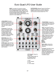
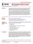
Euro Quad LFO User Guide
RATE/DIVISION: Manual Control of the Rate or
frequency of each LFO. In SYNC mode and
PHASE LOCK mode the function changes to
manual control of clock division from 1-16
WAVE: A possible 16 choices for waves.
Each wave can be morphed or transformed
by the TRANSFORM Control. TAB1-3 has 32
sub waves that morph smoothly. Pattern wave
has 32 pulse/gate patterns selectable by
Transform control. See the Wave section of this
manual for more detailed info.
QUAD LFO
LEVEL/RESET: Sets the
amplitude or level of the LFO
output. In Gate RSTST mode
this knob sets the wave reset
start point when a gate is
present.
LEVEL/RESET
GATE Inputs: Each LFO has
an associated gate input. The
gates are assigned by the gate
selection switch for reset and
sync functions.
G+
6
7 8 9 10
5
4
3
2
CV AMOUNT
4LFO
QUAD R
PHLOCK G
ROTATE Y
MODE
SWITCHES: Each of the
switches effects the way the
LFO operates. See Switch
section for details.
TRANSFORM
TRANSFORM: Changes the
waves dependent on the wave
selected. See more details in
Wave section.
WAVE
-R
CV Amount: Controls the
depth of modulation applied
thru the CV inputs to the
routing assigned by the
CV Route switch. Green
indicates positive CV, Red
is negative. LED off indicates
there is no modulation.
PULSE STAIR
UPDWN
SLOPE
CIRCLE
RAND
EXPO
RCOS
RISE
TAB1
RSAW
TAB2
SAW
TAB3
SINE
PAT TERN
16
1
5V
5V INV R
10V G
10V INV Y
2
RATE/DIV
LOW
R HIGH
POLARITY
RANGE/TAP
3
4
1
11
12
13
14
15
LFO EDIT
RESET
R RSTST
G HOLD
Y SYNC/TAP
GATE
FREQ
R LEVEL
G TRANS
Y WAVE
CV ROUTE
SAVE
EDIT: The QuadLFO uses a
“paging” system to edit. The 4
way rotary switch selects the
LFO 1-4 to edit. The pots and
switches become “live” for the
channel selected. All settings
can be stored in memory.
LEDs: Tapping the switches
changes the colours of the
LEDs. Each colour has a
corresponding function
associated.
R
G
Y
GATE1
GATE2
LFO1 CV
LFO2 CV
LFO3 CV
LFO4 CV
GATE3
GATE4
LFO1
LFO2
LFO3
LFO4
LFO Outputs: Output for
each of the
4 LFOs. Output range can
be changed with the
Polarity switch from:
1/ 0-5V
2/ 5-0V inverted
3/ +/-5V
4/ -/+5V inverted
pg1
=Off
=Red
=Green
=Yellow
Status LEDs: Indicate the
state of the LFO cycle and
frequency.
CV Inputs: Modulation inputs
that are routed to up to 4
destinations by the CV ROUTE
switch. All 4 destinations can
be active simultaneously per
LFO for a total of 16
modulation routes.
Button Switch Functions
Mode Switch: The mode Switch has 4 options and is responsible for the most significant changes to the way the module
operates. The modes and their functions are defined below.
4LFO: In this mode each of the 4 LFO function independently, each with their own frequency, wave, level and modulations.
Changes to the parameters of each LFO is done by selecting the LFO to edit with the LFO EDIT rotary switch knob.
The knobs become active and switch state LEDs update as each LFO is selected. This is the most typical mode when four
separate LFOs is needed.
Quad: Quad is short for Quadrature. LFO1 is the master in this mode and only LFO1 is editable. The module functions like a
single LFO with 4 outputs in quadrature phase in this mode. LFO1s controls are global and editing panel controls are disabled
for the other 3 LFOs. Outputs 2,3 and 4 are respectively 90, 180 and 270 degrees out of phase with LFO1 but are in sync.
They use the same wave, frequency, level, CV routing etc as LFO1. This is a useful mode for quad panning or barberpole
effects. Also makes an interesting gate sequencer when used with Pulse output waves.
PHLOCK: Is Phase Locked mode. LFO1 sets the RATE or frequency for all 4 LFOs but each LFO can be a division of the
master frequency. When editing LFO1 the RATE knob functions as it says. When editing LFOs 2-4 the RATE knob becomes
the control for setting the division of the LFO1 master frequency. Each LFO can have a different wave, level etc. This can be a
very unique mode especially when used with the last wave PATTERN. Each LFO can be outputting a different rhythm but all
are in sync and can be different divisions. Makes a great generator for drum patterns.
Rotate: Rotate mode functions the same as 4LFO mode with the exception being that pulses to the GATE1 input
cause the LFOs to rotate to the right. For example after the first pulse LFO1 outputs on LFO2 out, LFO2 on output 3
LFO3 on output 4 and LFO4 on output 1. Each subsequent rotates this order 1 output to the right. This is a unique feature
similar to feeding the 4 LFOs to a sequential switch module. Some very complex modulations are possible in this mode.
SAVE: To save all edits depress and hold the MODE/SAVE button for approximately 2 seconds (count 1000 and 1, 1000 and 2
at a moderate pace). The row of coloured buttons will flash sequentially when button is release to indicate save was
successful. If only the Mode LED changes colour the hold was too short.
Polarity Switch: This switch is used to set the ouput range and inversion. There are 4 positions available.
5V: The output swings between 0 and 5V and doesn’t go negative. The LEVEL control can be used to reduce this range
like a volume control. When level is at 0 the output is 0V
5V INV: Is the same 0-5V range but waves are inverted. A rising STAIR wave becomes a falling STAIR for example.
10V: The output swings between +5V and -5V. The LEVEL control can be used to reduce this range but in this case it does so
symmetrical. For example at half level the output will be +/-2.5V.
10V INV: The output swings between +5V and -5V same as 10V setting. Once again the output is an inverted version of the
above.
Range Switch: The range switch sets the frequency or rate range for each LFO. The LOW range is .003Hz-51Hz and
the HIGH range 10Hz-1.6kHz. The low range is used for typical LFO duties while the high range extends into the audio range
ideal for FM modulation and also as a standalone audio source for drones etc. It is possible to control the pitch in this range
with CV but it is not setup for accurate 1V/Oct tracking although it is possible to get close by adjusting the CV Amount. The
morphing waves TAB1-3 can be an excellent source of audio textures in the high range.
synchronized clocking is possible. In this mode the function of the RATE knob changes to DIVision. The possible divisions of
the input clock are 1-16. The TAP button can be used instead to set the frequency in place of external clock. The division knob
has no effect when using the TAP button to enter frequency. Tapping at least 3-4 times in a steady beat is best for accuracy.
pg2
Switches Continued
Gate Switch: The Gate switch selects how the LFOs will respond when a pulse/clock is patched to the GATE input jacks.
There are 4 different responses available.
Reset: This is a pretty straight forward function similar to hard sync on a VCO. Each pulse resets the LFO to the start of the
waveform 0.
RSTST: This mode is for Reset Start. This is similar to the RESET above but adds the capability to set the point at which the
waveform resets from 0-100%. The panel control for this is the Level/Reset knob panel top left. In this Gate Mode the level has
no effect having had its function replaced by Reset Start position. LFO amplitude is fixed at full scale or 100%. Also the LEVEL
CV modulation routing is now used to control the waveform start as well. Having control over the Reset position in the
waveform adds another unique dimension to shaping the way the LFOs cycle.
Hold: In this Gate mode holding the gate input high FREEZES the LFO cycle position. When the gate returns to low state the
LFO resumes cycling.
Sync/Tap: The Sync mode functions like a frequency counter. Using a timer it calculates the time or period between
pulses/clocks on the gate input jack and sets the LFO frequency to match. There is a separate gate input for each of the 4
LFOs so 4 different clocks can be used simultaneously. The RATE/DIV knob controls the division of the clock in this mode and
is able to divide the sync clock from 1-16 divisions including odd values. The TAP button can also be used to set the frequency.
Tapping 3 or 4 times at a steady pace to allow the timer to find an average is best for accuracy. The Rate/Division knob has no
effect when tapping.
CV Route Switch: The CV Route switch assigns the CV input jacks to the 4 destinations for internal modulation.
Each of the 4 destinations can be modulated simultaneously. Even though only one LED colour is showing the other 3 can still
be active. The CV AMOUNT knob controls the depth of modulation and the CV AMOUNT LED indicates the polarity of the
modulation. GREEN= Positive+ and RED= Negative-. When LED is off the CV amount is 0 or none. The LED is also a handy
indication of whether CV routing is active for a given Route selection. When stepping through the Routing switch destinations
if the CV AMT LED is lit it is an indication that routing is assigned. If LED is off then no routing is assigned.
Holding the CV ROUTE switch in a depressed state for 2 seconds will remove all CV Routings from the active LFO channel.
This is a convenient way to get back to default state with all CV Routings OFF.
Input Jacks: The range of input for the CV jacks is 0 - +/-5V. The high level pulse for the GATE inputs is ideally 5V but
10V will also work without damaging the module.
WAVES
LFO Waveforms: There are 16 waveforms to choose from using the WAVE selection knob. Each wave can be
transformed or shaped in a manner that is different for each of the waves available. Please visit the web page
http://www.modcan.com/emodules/quadlfowaves.html to see Oscilloscope screen captures that illustrate the effect of the
TRANSFORM pot as it is rotated from 0 to fully clockwise. The same changes are also possible by assigning the CV input to
TRANS. Think of it like an advanced Pulse Width Modulation feature on a standard LFO.
The TAB1-3 contain 32 waves which are morphed smoothly with the transform control. The PATTERN wave uses the transform
knob to select the 1-32 patterns.
pg3