1
AT&T
AT&T 555-610-140
Issue 1
August 1991
MERLIN LEGEND™
Communications System
Installation, Programming,
& Maintenance
Copyright © 1991 AT&T
All Rights Reserved
Printed in U.S.A.
AT&T 555-610-140
Issue 1
August 1991
Notice
Every effort was made to ensure that the information in this book was
complete and accurate at the time of printing. However, information is
subject to change.
Federal Communications Commission (FCC) and
Canadian Department Of Communications (DOC) Information
For important FCC and DOC interference, registration, and repair
information, see “Customer Support Information” in this book.
Trademarks
Accunet is a registered trademark of AT&T.
Dimension is a registered trademark of AT&T.
Horizon is a registered trademark of AT&T.
Magic on Hold is a registered trademark of AT&T.
Megacom is a registered trademark of AT&T.
MERLIN is a registered trademark of AT&T.
MERLIN LEGEND is a trademark of AT&T.
MERLIN MAIL is a trademark of AT&T.
MLX-10, MLX-10D, MLX-20L, and MLX-28D are trademarks of AT&T.
MultiQuest is a registered trademark of AT&T.
SYSTIMAX is a trademark of AT&T.
MS-DOS is a registered trademark of Microsoft Corporation.
PagePac is a registered trademark of DRACON, a Harris Corporation.
Starset is a registered trademark of Plantronics Corporation.
Supra and StarMate are trademarks of Plantronics Corporation.
UNIX is a registered trademark of UNIX System Laboratories, Inc.
ZoneMate is a trademark of DRACON, a Division of Harris Corporation.
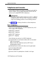
Support Telephone Number
AT&T provides a toll-free customer Helpline (1-800-628-2888)24 hours a
day (U.S.A. only). Call the Helpline, or your authorized dealer, if you need
assistance when installing, programming, or using your system.
ERRATA
MERLIN LEGEND™ Communications System
Installation, Programming, and Maintenance
555-610-140
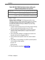
Ignore all references to the small processor module. The MERLIN LEGEND™ Communications
System offers only one processor module. This processor module is referred to as a large processor
module in this document.
Ignore references to the “small” processor module on the following pages:
Page 1-6, Processor Module.
Page 1-35, System Capacities, first, fourth, and sixth paragraphs.
Pages 1-36 - 1-37, Table 1-8, System Capacities.
Pages 1-38 - 1-40, Table 1-9, Feature Capacities.
Page 2-6, Backboard Requirements.
Page 3-10, Install the Feature Module in the Processor Module, first paragraph.
Appendix C - Page C-1
Ordering Codes Table: The following Price Element Codes (PECs) am not valid:
Small (Analog) - 6141-CUA
Small (Digital) - 6141-CUD
Appendix C - Page C-2
Ordering Codes Table: The following Price Element Codes (PECs) are not valid:
Small (Analog) - 6141-24D
Upgrade from Small to Large 6140-USLA
October 1, 1991
Contents
Customer Support Information
■
■
■
■
■
■
■
■
Support Telephone Number
FCC Electromagnetic Interference Information
DOC Interference Information
FCC Notification and Repair Information
Installation and Operational Procedures
DOC Notification and Repair Information
Security
Warranty and Liability
About The Book
■
■
■
■
■
Related Documentation
How to Order Books
Additional Ordering Information
Product Safety Labels
How to Comment on This Book
xv
xv
xv
xv
xvi
xvii
xviii
xxi
xxii
xxv
xxv
xxvi
xxviii
xxviii
xxviii
i
Contents
1
System Description
■
■
■
■
■
■
■
■
■
■
■
■
2
Preparation
■
■
■
■
■
■
ii
Modes of Operation
System Components
Control Unit
Telephones and Consoles
Adjuncts
Adapters
System Capacities
Data Capabilities
Networking Capabilities
Functional Units
Signal Processing
DS1 Capabilities
Planning Forms
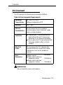
Environment
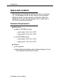
Space and Location
Power and Grounding
Power Surge and Lightning Protection
Unit Loads
1-1
1-2
1-4
1-5
1-26
1-34
1-34
1-35
1-41
1-42
1-45
1-47
1-53
2-1
2-2
2-5
2-6
2-8
2-14
2-15
Contents
3
Installation
■
■
■
■
■
■
■
■
4
The Control Unit
Channel Service Unit
The SMDR Printer and the System
Programming PC
Data Adapters
System Wiring
IROB Protection
Telephones and Consoles
System Acceptance Test
Programming Procedures
■
■
■
■
■
■
■
■
■
■
■
■
■
■
System Programming
Programming Procedures
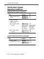
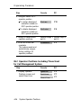
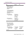
Set the Basic System Operating Conditions
System Renumbering
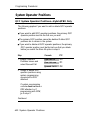
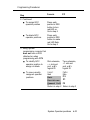
System Operator Positions
Lines and Trunks
DS1 Facilities
Tie Trunks
DID Trunks
PRI Facilities
Telephones
Auxiliary Equipment
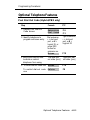
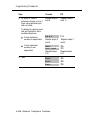
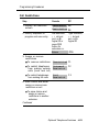
Optional Telephone Features
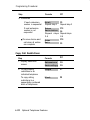
Optional Operator Features
3-1
3-2
3-19
3-45
3-56
3-77
3-102
3-103
3-116
4-1
4-1
4-11
4-12
4-17
4-22
4-27
4-43
4-52
4-62
4-71
4-97
4-109
4-119
4-132
iii
Contents
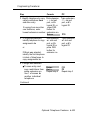
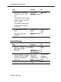
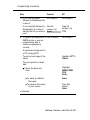
Programming Procedures—Continued
■
■
■
■
■
■
5
Maintenance and Troubleshooting
■
■
6
■
■
Adapters
Accessories
Applications
Wiring
■
■
iv
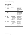
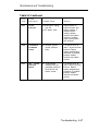
Maintenance
Troubleshooting
4-146
4-173
4-202
4-215
4-222
4-228
5-1
5-1
5-46
Adapters, Accessories, and Applications 6-1
■
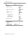
A
Optional Group-Assigned Features
System Features
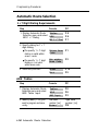
Automatic Route Selection
Night Service
Labeling
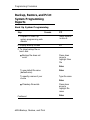
Backup, Restore, and Print System
Programming Reports
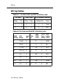
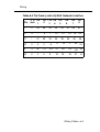
Wiring Tables
Wiring Diagrams
6-1
6-4
6-8
A-1
A-2
A-6
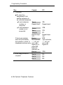
Contents
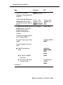
B
Adjuncts
B-1
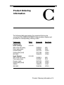
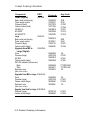
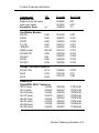
C
Product Ordering Information
C-1
D
Unit Load Calculation Work Sheet
D-1
E
General Telephone Programming
Programming Methods
E-1
E-2
F
General Feature Use
F-1
G
Programming Special Characters
G-1
H
System Programming Console Overlay
H-1
■
v
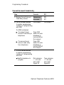
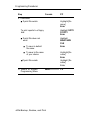
Contents
I-1
I
System Programming Reports
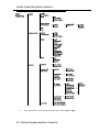
J
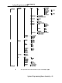
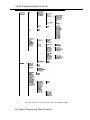
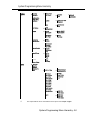
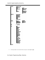
System Programming Menu Hierarchy J-1
K
Two-Digit Numbering Plan
K-1
L
System Technician’s Run Sheet
L-1
AB
Abbreviations
ABB-1
GL
Glossary
GL-1
IN
Index
Illustrations
vi
IN-1
inside
back
cover
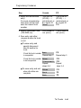
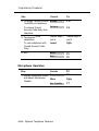
Tables
1
System Description
1-1
1-2
1-3
1-4
1-5
1-6
1-7
1-8
1-9
1-10
1-11
2
Line/Trunk and Station Modules
Touch-Tone Receiver Requirements
Reusable MERLIN II Line/Trunk and
Station Modules
Reusable MERLIN II Hardware
Analog Multiline Telephones
Single-Line Telephones
Telephones and Adjuncts Not Supported
System Capacities
Feature Capacities
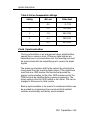
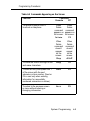
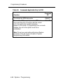
Tie-Trunk Compatibility
Line Compensation Settings
1-9
1-21
1-22
1-24
1-28
1-30
1-32
1-36
1-38
1-52
1-59
Preparation
2-1
2-2
2-3
2-4
2-5
Required Planning Forms
Required Planning Forms for 100D,
400EM, or 800 DID Modules
Optional Planning Forms
Environmental Requirements
AC Power Requirements
2-2
2-3
2-3
2-5
2-8
vii
Tables
3
Installation
3-1
3-2
3-3
3-4
3-5
3-6
3-7
3-8
3-9
3-10
3-11
3-12
3-13
3-14
3-15
3-16
3-17
3-18
3-19
3-20
3-21
viii
3-21
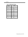
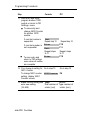
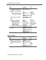
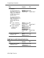
SW1 Default Settings
3-22
SW2 Default Settings
3-23
SW4 Default Settings
3-24
SW5 Default Settings
3-25
SW6 Default Settings
3-26
SW7 Settings
3-27
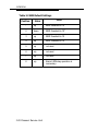
SW2 BER Options
Switch Settings in Hybrid/PBX Mode:
Network and Equipment are ESF Framed 3-28
Switch Settings in Hybrid/PBX Mode:
3-28
Network and Equipment are D4 Framed
Switch Settings in Hybrid/PBX Mode:
Network is ESF Framed and Equipment
3-29
is D4 Framed
Switch Settings in Hybrid/PBX Mode:
Network is D4 Framed and Equipment
3-29
is ESF Framed
3-31
Artificial Transmit Line Options
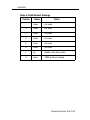
3-32
100D Module Pin Assignments
3-32
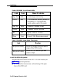
Wire-Wrap Connector Pin Assignments
3-33
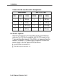
DTE 15-Pin Connector Pin Assignments
Network 15-Pin Connector Pin Assignments 3-34
3-35
CSU Front Panel LEDs
3-36
CSU Front-Panel Controls
3-37
CSU Front-Panel Test Jacks
3-39
SMU Switch Settings
3-40
OR Power Mode Option Settings
Tables
3-22
3-23
3-24
3-25
3-26
3-27
3-28
3-29
3-30
3-31
3-32
3-33
3-34
4
3-40
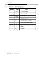
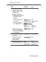
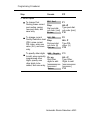
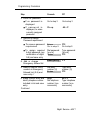
OR Artificial Line Options
3-42
SMU Front-Panel LEDs
3-42
SMU Front Panel Test Jacks
3-44
CSU Rear Panel Pin Assignments
3-47
AT&T 572 Printer Options
AT&T 475/476 Printer DIP Switch Settings 3-49
ISDN 7500B Data Module Option Settings
for Digital-to-Analog Modem Pool Operation 3-72
Modem Option Setting for Digital-to-Analog
3-73
Modem Pool Operation
ISDN 7500B Data Module Option Settings for
3-74
Analog-to-Digital Modem Pool Operation
Modem Option Setting for Analog-to-Digital
3-75
Modem Pool Operation
3-79
Network Interfaces
3-80
CO Network Interface Codes
3-97
Insert Labels
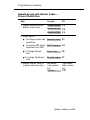
Programming Procedures
4-1
4-2
4-3
4-4
4-5
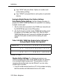
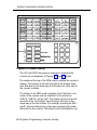
SPM Main Menu Options
System Programming Menu Options
Commands Using Fixed Buttons
Commands Appearing on the Screen
Commands Applicable Only to SPM
4-4
4-5
4-8
4-9
4-10
ix
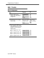
Tables
5
Maintenance and Troubleshooting
5-1
5-2
6
A-2
A-3
A-4
A-5
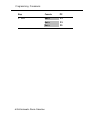
6-10
6-23
6-28
6-32
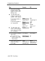
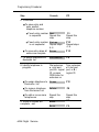
LS, GS/LS, DID, and OPT 6-Position
Jacks
Tie-Trunk and DS1/PR1 8-Position Jacks
Tie-Line Jack to RJ2GX Network
Interface
T/R, Analog Multiline Telephone, and MLX
8-Position Station Jacks
Eight-Pin RS-232 Flow Control Cable
A-2
A-2
A-3
A-4
A-5
Adjuncts
B-1
x
TTRs Required by VMS
Voice Channels Required
Number of Attendants
MERLIN MAIL Ports Required
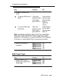
Wiring
A-1
B
5-44
5-46
Adapters, Accessories, and Applications
6-1
6-2
6-3
6-4
A
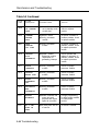
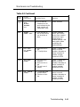
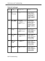
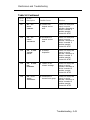
Line/Trunk Errors
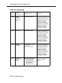
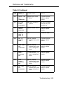
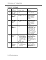
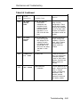
Maintenance Problems and Solutions
Adjunct Types and Specifications
B-2
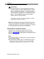
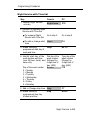
CUSTOMER WARNING
This manual is designed for use by qualified service
technicians only. Technician qualification includes completion
of an AT&T hands-on instructor-led course covering installation
and maintenance for this product. Installation or maintenance of
this product by anyone other than a qualified service technician
may void the warranty. Hazardous electrical voltages are
present inside this product
The exclamation point in an equilateral
triangle is intended to alert the user to
the presence of important operating
and maintenance (servicing)
instructions in the literature
accompanying the product.
IMPORTANT SAFETY INSTRUCTIONS
When installing telephone equipment, basic safety
precautions should always be followed to reduce the risk of
fire, electric shock, and injury to persons, including:
■ Read and understand all instructions.
■ Follow all warnings and instructions marked on or packed
with the product.
■ Never install telephone wiring during a lightning storm.
xi
■
■
■
■
■
■
■
■
■
■
■
■
xii
Never install telephone jacks in a wet location unless the
jack is specifically designed for wet locations.
Never touch uninsulated telephone wires or terminals
unless the telephone wiring has been disconnected at the
network interface.
Use caution when installing or modifying telephone lines.
Use only AT&T manufactured MERLIN LEGEND™ Communications System circuit modules, carrier assemblies,
and power units in the MERLIN LEGEND Communications
System (511A) control unit.
Use only AT&T-recommended/approved MERLIN LEGEND
Communications System accessories.
If equipment connected to the analog station modules
(008/408/408 GS/LS) or to the MLX telephone module (008
MLX) is to be used for in-range out-of-building (IROB)
applications, IROB protectors are required.
Do not install this product near water, for example, in a wet
basement location.
Do not overload wall outlets as this can result in the risk of
fire or electric shock.
The MERLIN LEGEND Communications System is
equipped with a three-wire grounding-type plug, a plug
having a third (grounding) pin. This plug will fit only into a
grounding-type power outlet. This is a safety feature. if you
are unable to insert the plug into the outlet, contact an
electrician to replace the obsolete outlet. Do not defeat the
safety purpose of the grounding plug.
The MERLIN LEGEND Communications System requires a
supplementary ground.
Do not attach the power supply cord to building surfaces.
Do not allow anything to rest on the power cord. Do not
locate this product where the cord will be abused by
persons walking on it.
Slots and openings in the module housings are provided
for ventilation. To protect this equipment from overheating,
do not block these openings.
■
■
Never push objects of any kind into this product through
module openings or expansion slots, as they may touch
dangerous voltage points or short-out parts, which could
result in a risk of fire or electric shock. Never spill liquid of
any kind on this product.
Unplug this product from the wall outlet before cleaning.
Do not use liquid or aerosol cleaners on this product. Use
a damp cloth for cleaning.
xiii
Customer Support
Information
Support Telephone Number
AT&T provides a toll-free customer Helpline (1-800-628-2888)24 hours a
day (U.S.A. only). Call the Helpline, or your authorized dealer, if you need
assistance when installing, programming, or using your system.
Federal Communications Commission (FCC)
Electromagnetic Interference Information
This equipment has been tested and found to comply with the limits for a
Class A digital device, pursuant to Part 15 of the FCC Rules. These limits
are designed to provide reasonable protection against harmful interference
when the equipment is operated in a commercial environment. This
equipment generates, uses, and can radiate radio frequency energy and, if
not installed and used in accordance with the instruction manual, may
cause harmful interference to radio communications. Operation of this
equipment in a residential area is likely to cause harmful interference, in
which case the user will be required to correct the interference at his own
expense.
Canadian Department of Communications (DOC)
Interference Information
This digital apparatus does not exceed the Class A limits for radio noise
emissions set out in the radio interference regulations of the Canadian
Department of Communications.
Customer Support Information
xv
Customer Support Information
Le présent appareil numérique n'émet pas de bruits radioélectriques
dépassant les limites applicable aux appareils numériques de la classe A
prescrites dans le Règlement sur le brouillage radioélectrique édicté par le
ministère des Communications du Canada.
FCC Notification and Repair Information
This equipment is registered with the FCC in accordance with Part 68 of its
rules. In compliance with those rules, you are advised of the following:
■ Means of Connection. Connection of this equipment to the telephone
network shall be through a standard network interface jack: USOC
RJ11C, RJ14C, RJ21X. Connection to E&M tie trunks requires a USOC
RJ2GX. Connection to off-premises stations requires a USOC RJ11C or
RJ14C. Connection to 1.544 Mbs digital facilities must be through a
USOC RJ48C or RJ48X. Connection to DID requires a RJ11C, RJ14C or
RJ21X. These USOCs must be ordered from your telephone company.
This equipment may not be used with party lines or coin telephone lines.
■
Notification to the Telephone Companies. Before connecting this
equipment, you or your equipment supplier must notify your local
telephone company’s business office of the following:
■
The telephone number(s) you will be using with this equipment.
■
The appropriate registration number and ringer equivalence number
(REN), which can be found on the back or bottom of the control unit
is as follows:
If this equipment is to be used as Key System, report the
following number AS593M-72914-KF-E and if the system
provides both manual and automatic selection of incoming/
outgoing access to the network, report AS593M-72682-MF-E.
The ringer equivalence number for both systems is 1.5A.
For tie-line connection, provide the telephone company the facility
■
interface code (FIC) of TL31M and the service order code (SOC)
9.0F.
For connection to off-premises stations, report the FIC OL13C and
■
SOC 9.0F.
If this equipment is to be connected to digital service (1.544 Mbs),
■
the FIC is 04DU9-B for D4 framing format or 04DU9-C for extended
framing format, and SOC 6.0P.
■
If this equipment is to be connected to DID facilities, the FIC is
02RV2-T, and the SOC is 9.0F.
The quantities and USOC numbers of the jacks required for each
■
jack provide the sequence in which lines are to be connected: the
type lines, the FIC, and REN by position when applicable.
xvi Customer Support Information
Customer Support Information
You must also notify your local telephone company if and when this
equipment is permanently disconnected from the line(s).
The REN is used to determine the quantity of devices which maybe
connected to the telephone line. Excessive REN’s on the telephone line
may result in the devices not ringing in response to an incoming call. In
most, but not all, areas the sum of the REN’s should not exceed five
(5.0). To be certain of the number of devices that maybe connected to
the line, as determined by the total REN’s, contact the telephone
company to determine the maximum REN for the calling area.
Installation and Operational Procedures
The manuals for your system contain information about installation and
operational procedures.
■ Repair Instructions. If you experience trouble because your equipment
is malfunctioning, the FCC requires that the equipment not be used and
that it be disconnected from the network until the problem has been
corrected. Repairs to this equipment can be made only by the
manufacturers, their authorized agents, or by others who maybe
authorized by the FCC. In the event repairs are needed on this
equipment, please contact the National Service Assistance Center
(NSAC) at 1-800-628-2888, or your authorized AT&T dealer.
■ Rights of the Local Telephone Company. If this equipment causes
harm to the telephone network, the local telephone company may
discontinue your service temporarily. If possible, they will notify you in
advance. But if advance notice is not practical, you will be notified as
soon as possible. You will also be informed of your right to file a
complaint with the FCC.
Your local telephone company may make changes in its facilities,
equipment operations, or procedures that affect the proper functioning
of this equipment. If they do, you will be notified in advance to give you
an opportunity to maintain uninterrupted telephone service.
■ Hearing Aid Compatibility. The custom telephone sets for this system
are compatible with inductively coupled hearing aids as prescribed by
the FCC.
■ Automatic Dialers. WHEN PROGRAMMING EMERGENCY NUMBERS
AND/OR MAKING TEST CALLS TO EMERGENCY NUMBERS:
■ Remain on the line and briefly explain to the dispatcher the reason
for the call.
■ Perform such activities in the off-peak hours, such as early morning
or late evening.
Customer Support Information
xvii
Customer Support Information
DOC Notification and Repair Information
NOTICE: The Canadian Department of Communications (DOC) label
identifies certified equipment. This certification means that the equipment
meets certain telecommunications network protective, operational, and
safety requirements. The DOC does not guarantee the equipment will
operate to the user’s satisfaction.
Before installing this equipment, users should ensure that it is permissible to
connect it to the facilities of the local telecommunications company. The
equipment must also be installed using an acceptable method of
connection. In some cases, the company’s inside wiring for single-line
individual service may be extended by means of a certified connector
assembly (telephone extension cord). The customer should be aware that
compliance with the above conditions may not prevent degradation of
service in some situations.
Repairs to certified equipment should be made by an authorized Canadian
maintenance facility designated by the supplier. Any repairs or alterations
made by the user to this equipment, or any equipment malfunctions, may
give the telecommunications company cause to request the user to
disconnect the equipment.
Users should ensure for their own protection that the electrical ground
connections of the power utility, telephone lines, and internal metallic water
pipe system, if present, are connected. This precaution maybe particularly
important in rural areas.
CAUTION: Users should not attempt to make such connections
themselves, but should contact the appropriate electric inspection authority
or electrician, as appropriate.
To prevent overloading, the Load Number (LN) assigned to each terminal
device denotes the percentage of the total load to be connected to a
telephone loop used by the device. The termination on a loop may consist
of any combination of devices subject only to the requirement that the total
of the Load Numbers of all the devices does not exceed 100.
DOC Certification No. 230 4095A
CSA Certification No. LR 56260
Load No. 6
xviii
Customer Support Information
Customer Support Information
Renseignements sur la notification du ministère des
Communications du Canada et la réparatione
AVIS: L'étiquette du ministère des Communications du Canada identifie le
matériel homologué. Cette étiquette certifie que le matériel est conforme à
certaines normes de protection, d'exploitation et de sécurité des réseaux
de télécommunications. Le Ministère n’assure toutefois pas que le matériel
fonctionnera à la satisfaction de l’utilisateur.
Avant d'installer ce matériel, l'utilisateur doit s’assurer qu'il est permis de le
raccorder aux installations de l’entreprise locale de télécommunication. Le
matériel doit également etre installé en suivant une méthode acceptée de
raccordement. Dans certains cas, les fils intérieurs de l’enterprise utilisés
pour un service individuel à ligne unique peuvent être prolongés au moyen
d’un dispositif homologué de raccordement (cordon prolongateur
téléphonique interne). L'abonné ne doit pas oublier qu'il est possible que la
conformité aux conditions énoncées ci-dessus n’empêchent pas la
dégradation du service dans certaines situations. Actuellement, les
entreprises de télécommunication ne permettent pas que l'on raccorde leur
matériel à des jacks d'abonné, sauf dans les cas précis prévus pas les
tarifs particuliers de ces entreprises.
Les réparations de matériel homologué doivent être effectuées pas un
centre d'entretien canadien autorisé désigné par le fournisseur. La
compagnie de télécommunications peut demander à l'utilisateur de
débrancher un appareil à la suite de réparations ou de modifications
effectuées par l’utilisateur ou à cause de mauvais fonctionnement.
Pour sa propre protection, l'utilisateur doit s'assurer que tous les fils de
mise à la terre de la source d'énergie électrique, des lignes téléphoniques
et des canalisations d'eau métalliques, s'il y en a, sont raccordés ensemble.
Cette précaution est particulièrement importance dans les régions rurales.
AVERTISSEMENT: L'utilisateur ne doit pas tenter de faire ces
raccordements lui-même; il doit avoir recours à un service d'inspection des
installations électriques, ou à un electricien, selon le cas.
L'indice de charge (IC) assigné à chaque dispositif terminal indique, pour
éviter toute surchage, le pourcentage de la charge totale qui peut être
raccordée à un circuit téléphonique bouclé utilisé par ce dispositif. La
terminaison du circuit bouclé peut être constitutée de n'importe quelle
combinaison de dispositifs, pourvu que la somme des indices de charge de
l’ensemble des dispositifs ne dépasse pas 100.
No d’homologation 230 4095A
No de certification CSA: LR 56260
L'indice de charge: 6
Customer Support Information
xix
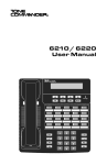
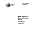
LISTED
TELEPHONE
EQUIPMENT
Use only AT&T manufactured MERLIN LEGEND circuit modules.
career assemblies, and power units. as specified in the
Installation Manual, in this product. There are no user serviceable
parts inside. Contact your authorized agent for service and repair
This digital apparatus does not exceed the Class A limits for radio
noise emissions set out in the radio interference regulations of the
Canadian Department of Communications.
Le présent appareil numérique n'émet pas de bruits
radioélectriques dépassant les limites applicables aux appareils
numériques de la classe A prescrites dans le Réglement sur le
brouillage radioélectrique édicté par le ministére des
Communications du Canada.
MADE IN USA
538E
Si l'équipment est
utilisé pour des applications extérieures,
l'installation d'un protecteur secondair est
requise. Voir le manuel d'installation.
AVERTISSEMENT
DR ID
CANADA
FCC Rules FCC Reg. No
Equivalence 1.5A. When equipped
(key only), FCC Reg. No.
Equivalence 1.5A.
If equipment is used for
out-of-building applications, approved
secondary protectors are required. See
Installation Manual.
Complies with Part 68
AS593M-72682-MF-E Ringer
w i t h t h e KF option
AS593M-72914-KF-E Ringer
WARNING:
LR 56260
MERLIN LEGEND™
Model 511 A Control Unit
AT&T
This device complies with Part 15 of the FCC Rules. Operation is
subject to the following two conditions. (1) this device may not
cause harmful interference. and (2) this device must accept any
interference received, including interference that may cause
undesired operation
Customer Support Information
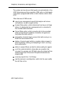
Security of Your System—Preventing Toll Fraud
As a customer of a new telephone system, you should be aware that there
exists an increasing problem of telephone toll fraud. Telephone toll fraud
can occur in many forms, despite the numerous efforts of telephone
companies and telephone equipment manufacturers to control it. Some
individuals use electronic devices to prevent or falsify records of these
calls. Others charge calls to someone else’s number by illegally using lost
or stolen calling cards, billing innocent parties, clipping on to someone
else’s line, and breaking into someone else’s telephone equipment
physically or electronically. In certain instances, unauthorized individuals
make connections to the telephone network through the use of remote
access features.
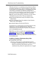
The Remote Access feature of your system, if you choose to utilize it,
permits off-premises callers to access the system from a remote telephone
by using an 800 number or a 7- or 10- digit telephone number. The system
returns an acknowledgement signaling the user to key in his or her
authorization code, which is selected and administered by the system
manager. After the authorization code is accepted, the system returns dial
tone to the user. If you do not program specific egress restrictions, the user
will be able to place any call normally dialed from a telephone associated
with the system. Such an off-premises network call is originated at, and wiII
be billed from, the system location.
The Remote Access feature, as designed, helps the customer, through
proper administration, to minimize the ability of unauthorized persons to
gain access to the network. Most commonly, phone numbers and codes are
compromised when overheard in a public location, through theft of a wallet
or purse containing access information, or through carelessness (writing
codes on a piece of paper and improperly discarding it). Additionally,
hackers may use a computer to "dial" an access code and then publish the
information to other hackers. Enormous charges can be run up quickly. It is
the customer’s responsibility to take the appropriate steps to properly
implement the features, evaluate and administer the various restriction
levels, protect access codes, and distribute access codes only to
individuals who have been fully advised of the sensitive nature of the
access information.
Common carriers are required by law to collect their tariffed charges. While
these charges are fraudulent charges made by persons with criminal intent,
applicable tariffs state that the customer of record is responsible for
payment of all long distance or other network charges. AT&T cannot be
responsible for such charges and will not make any allowance or give any
credit for charges that result from unauthorized access.
Customer Support Information xxi
Customer Support Information
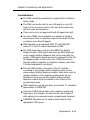
To minimize the risk of unauthorized access to your communications
system:
■
■
■
■
■
■
■
■
■
Use a nonpublished Remote Access number.
Assign authorization codes randomly to users on a "need-to-have" basis,
keeping a log of ALL authorized users and assigning one code to one
person.
Use random sequence authorization codes, which are less likely to be
easily broken.
Deactivate all unassigned codes promptly.
Ensure that Remote Access users are aware of their responsibility to
keep the telephone number and any authorization codes secure.
When possible, restrict the off-network capability of off-premises callers,
via use of Call Restrictions and Disallowed List capabilities.
When possible, block out-of-hours calling.
Frequently monitor system call detail reports for quicker detection of any
unauthorized or abnormal calling patterns.
Limit Remote Call Forward to persons on a “need-to-have” basis.
Limited Warranty and Limitation of Liability
Limited Warranty
AT&T warrants to you, the customer, that your MERLIN LEGEND
Communications System will be in good working order on the date AT&T or
its authorized reseller delivers or installs the system, whichever is later
(“Warranty Date"). If you notify AT&T or its authorized reseller within one year
of the Warranty Date that your system is not in good working order, AT&T
will without charge to you repair or replace, at its option, the system
components that are not in good working order. Repair or replacement
parts may be new or refurbished and will be provided on an exchange
basis. If AT&T determines that your system cannot be repaired or replaced,
AT&T will remove the system and, at your option, refund the purchase price
of your system, or apply the purchase price towards the purchase of
another AT&T system.
xxii Customer Support Information
Customer Support Information
If you purchased your system directly from AT&T, AT&T will perform
warranty repair in accordance with the terms and conditions of the specific
type of AT&T maintenance coverage you selected. A written explanation of
AT&T’s types of maintenance coverage maybe obtained from AT&T by
calling 1-800-247-7000. If you purchased your system from an AT&T
authorized reseller, contact your reseller for the details of the maintenance
plan applicable to your system.
This AT&T limited warranty covers damage to the system caused by power
surges; including power surges due to lightning.
The following will not be deemed to impair the good working order of the
system, and AT&T will not be responsible under this limited warranty for
damages resulting from
■ failure to follow AT&T’s installation, operation, or maintenance
instructions
■
■
■
■
unauthorized system modification, movement, or alteration
unauthorized use of common carrier communication services accessed
through the system
abuse, misuse, or negligent acts or omissions of the customer and
persons under the customer’s control
acts of third parties and acts of God
AT&T’S OBLIGATION TO REPAIR, REPLACE, OR REFUND AS SET FORTH
ABOVE IS YOUR EXCLUSIVE REMEDY.
EXCEPT AS SPECIFICALLY SET FORTH ABOVE, AT&T, ITS AFFILIATES,
SUPPLIERS, AND AUTHORIZED RESELLERS MAKE NO WARRANTIES,
EXPRESS OR IMPLIED, AND SPECIFICALLY DISCLAIM ANY WARRANTIES
OF MERCHANTABILITY OR FITNESS FOR A PARTICULAR PURPOSE.
Customer Support Information
xxiii
Customer Support Information
Limitation Of Liability
EXCEPT FOR PERSONAL INJURY, DIRECT DAMAGES TO TANGIBLE
PERSONAL PROPERTY PROXIMATELY CAUSED BY AT&T, AND LIABIILlTY
OTHERWISE EXPRESSLY ASSUMED IN A WRITTEN AGREEMENT SIGNED
BY AT&T, THE LIABILITY OF AT&T, ITS AFFILIATES, SUPPLIERS AND
AUTHORIZED RESELLERS FOR ANY CLAIMS, LOSSES, DAMAGES OR
EXPENSES FROM ANY CAUSE WHATSOEVER (INCLUDING ACTS OR
OMISSIONS OF THIRD PARTIES) REGARDLESS OF THE FORM OF
ACTION, WHETHER IN CONTRACT, TORT OR OTHERWISE, SHALL NOT
EXCEED AMOUNT EQUAL TO THE LESSER OF THE DIRECT
DAMAGES PROVEN OR THE PURCHASE PRICE OF THE SYSTEM. IN NO
EVENT SHALL AT&T OR ITS AFFILIATES, SUPPLIERS OR AUTHORIZED
RESELLERS BE LIABLE FOR INCIDENTAL, RELIANCE, CONSEQUENTLY,
OR ANY OTHER INDIRECT LOSS OR DAMAGE (INCLUDING LOST
PROFITS OR REVENUES) INCURRED IN CONNECTION WITH THE
SYSTEM. THIS LIMITATION OF LIABILITY SHALL SURVIVE FAILURE OF
THE EXCLUSIVE REMEDY SET FORTH IN THE LIMITED WARRANTY
ABOVE.
xxiv Customer Support Information
About This Book
This book provides technical information about the operation and
installation of the communications system. It is intended for
qualified technicians who install, maintain, and repair the
communications system.
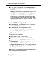
Related Documentation
The following books are available to help you set up, use, and
maintain the communications system:
■
reference
■
setup and modification
■
telephone user support
■
operator guides
■
miscellaneous
About This Book xxv
About This Book
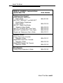
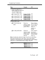
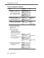
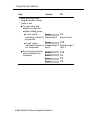
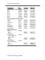
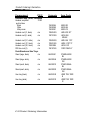
How to Order Books
The books needed for operating the communications system
were supplied with the system. You can order additional copies
of these and other books listed below from the AT&T Customer
Information Center:
■
Within the continental United States, call 1-800-432-6600.
■
In Canada, call 1-800-255-1242.
MERLIN LEGEND Communications
System Book Title
Order Number
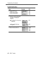
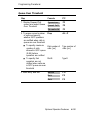
System Reference
System Reference
555-610-110
System Setup and Modification
Key System Planning Forms only
Key System Planning and Key
System Planning Forms
PBX System Planning Forms only
PBX System Planning and PBX
System Planning Forms
Data Planning Forms only
Data Guide and Data Planning Forms
System Programming.
xxvi About This Book
555-610-116
555-610-112
555-610-117
555-610-113
555-610-118
555-610-114
555-610-111
About This Book
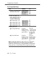
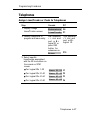
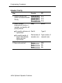
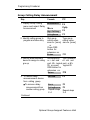
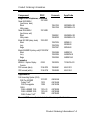
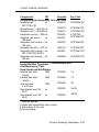
MERLIN LEGEND Communications
System Book Title
Telephone User Support
Analog Multiline Telephones
User's Guide
MLX-10D,™ MLX-28D,™ and MLX-20L™
Digital Display Telephones
User’s Guide
MLX-10™ Digital Non-Display
Telephone User's Guide
MLX-10™ and MLX-10D™ User Cards
MLX-28D™ and MLX-20L™ User Cards
Single-Line Telephones User’s Guide
Operator Guides
Analog Direct-Line Consoles
Operator’s Guide
Digital/ISDN Direct-Line Consoles
Operator’s Guide
Digital/ISDN Queued Call Console
Operator’s Guide
Miscellaneous
Calling Group Supervisor’s Guide
Order Number
555-610-120
555-610-122
555-610-123
555-610-124
555-610-125
555-610-121
555-610-131
555-610-132
555-610-133
555-610-130
About This Book xxvii
About This Book
Additional Ordering
Information
For information on ordering replacement parts, accessories, and
other equipment that is compatible with the system, see
Appendix A in System Reference.
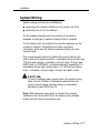
Product Safety Labels
Throughout this book, hazardous situations are indicated by an
exclamation point inside a triangle, along with the word caution
or warning.
WARNING
Warning indicates the presence of a hazard that could
cause death or severe personal injury if the hazard is not
avoided.
CAUTION:
Caution indicates the presence of a hazard that will or can
cause minor personal injury or property damage if the
hazard is not avoided.
How to Comment on This
Book
We welcome your feedback on this book. Please use the
feedback form that follows. If the form is missing, send your
comments to A. Sherwood, AT&T, 99 Jefferson Road,
Rm. #2A25, Parsippany, NJ 07054.
xxviii About This Book
System Description
The MERLIN LEGEND™ Communications System is an
advanced digital switching system that integrates voice and data
communications features. Voice features combine traditional
telephone features, such as Transfer and Hold, with advanced
features, such as Group Coverage and Park. Data features
provide switched data connections that enable the transmission
of voice and data over the same system wiring.
System Description 1-1
System Description
Modes of Operation
The system is designed for customers in the 10- to 100-station
range. It can be configured to operate in one of three modes:
■
Hybrid/PBX
■
Key
■
Behind Switch
Hybrid/PBX Mode
The Hybrid/PBX mode handles a large volume of calls and users
and provides the most flexibility of the three modes. Outside
facilities consist of Ioop-start trunks, ground-start trunks, direct
inward dialing (DID) trunks, tie trunks, and Digital Signal 1 (DS1)
facilities. The trunks can be grouped in pools for shared use. In
addition, trunks can be assigned to line buttons on multiline
telephones for users who need a personal line.
Users access inside lines and outside trunks via system access
buttons. To make an outside call, the user enters a dial-out code
(usually a 9), and the system automatically selects an available
trunk. The Automatic Route Selection feature determines which
trunk should be used for each type of outgoing call.
Incoming calls can be handled by a direct-line console (DLC) or
a queued call console (QCC), or by a combination of both
console types.
1-2 Modes of Operation
System Description
Key Mode
In the Key mode, each outside line appears on a button on one
or more multiline telephones. The line buttons allow users to see
activity on other telephones, join conversations, place calls, or
receive calls. Separate intercom buttons are used to make and
receive internal calls.
A Key system automatically assigns the first eight outside lines to
all telephones. This arrangement can be customized through
system programming by assigning lines to individual telephones
or to selected groups of telephones.
Behind Switch Mode
In the Behind Switch mode, the system is connected to a
Hybrid/PBX or Centrex system. This other system (called the
host) provides the interface to outside lines and some features.
A Behind Switch system assigns only one line (called a prime
line) to each telephone. Outside lines to telephones or groups of
telephones are assigned through system programming. In the
Behind Switch mode, people can use the special features of
both the MERLIN LEGEND Communications System and the host
system.
Modes of Operation 1-3
System Description
System Components
The system consists of required and optional components:
■
■
required components
■
control unit
■
telephones
optional components
■
adjuncts
■
adapters
■
applications
These components are described in the following pages.
1-4 System Components
System Description
Control Unit
The control unit (CU) connects central office (CO) lines with
telephones and adjuncts such as answering machines and fax
machines. The CU consists of the following components:
■
control unit housing
■
carrier(s)
■
power supply module (one per carrier)
■
processor module
■
line/trunk and station modules
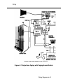
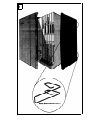
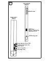
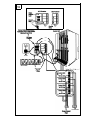
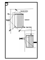
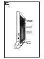
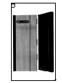
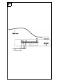
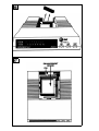
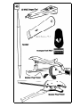
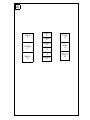
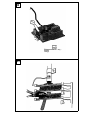
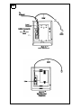
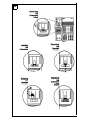
Control Unit Housing
The control unit is housed in a plastic cabinet for protection. The
size of the housing increases as expansion carriers are added to
the CU. Figure 1 shows how the control unit housing fits around
the CU.
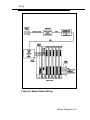
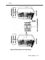
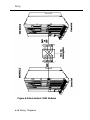
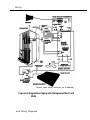
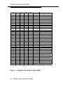
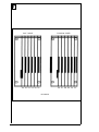
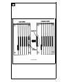
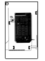
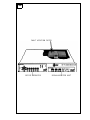
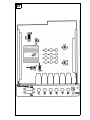
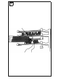
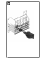
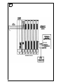
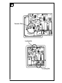
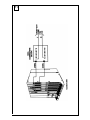
Carriers
The basic and expansion carriers each have seven slots to hold
modules (see Figure 2). The basic carrier contains a power
supply module, the processor module (slot 00), and line/trunk
and station modules (slots 01–05).
Up to two expansion carriers can be added to the right side of
the basic carrier to increase the capacity of the system. Like the
basic carrier, the leftmost and widest slot of the expansion
carrier holds a power supply module; the remaining six slots hold
line/trunk and station modules.
Besides the slots, both basic and expansion carriers have a
backplane with an input/output (I/O) bus that provides the
interfaces with the modules.
Control Unit 1-5
System Description
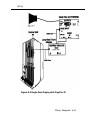
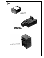
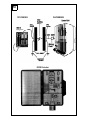
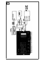
Power Supply Modules
The power supply module provides power to the carrier, to each
telephone, and to adjuncts—except for adjuncts such as
answering machines and fax machines that have their own
power supplies. Each carrier requires its own power supply
module, which goes into the first slot on the carrier.
The power supply module converts 117-VAC line voltage to
these outputs: +5 VDC, -5 VDC, and -48 VDC. All modules use
+5 VDC and -5 VDC for logic and analog transmission circuits.
Most line/trunk and station modules use -48 VDC for power to the
stations. The direct inward dialing (DID) and off-premises
telephone (OPT) line/trunk and station modules also provide
-48 VDC on the tip/ring (T/R) interface to the CO or OPT station.
The 012 basic telephone module provides 21 VDC to single-line
telephones and equipment.
When single-line telephones are connected to a 012, 800 DID, or
008 OPT module, a 129B Frequency Generator (ring generator)
must be installed in the power supply module of each carrier that
houses one or more of these modules.
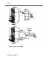
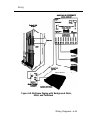
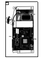
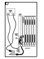
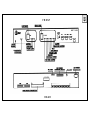
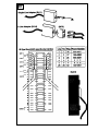
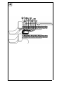
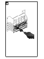
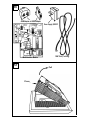
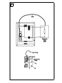
A green light on the power supply module remains on as long as
the module is receiving power. The power supply module also
has an on/off switch and a modular telephone jack for
connecting an auxiliary power unit as needed (see Figure 3).
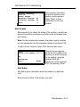
Processor Module
Placed in slot 00 of the basic carrier, the processor module
controls system features and programming via the processor
and memory boards and the feature module. The processor
module comes in small and large versions. The small processor
module supports up to 24 CO or tie lines/trunks and 56 stations.
The large processor module supports up to 80 CO or tie
lines/trunks and 144 stations.
1-6 Control Unit
System Description
The main board contains the 68000 microprocessor, a built-in
1200-baud data modem, built-in diagnostics, RAM, a real-time
clock, and interrupt circuitry, and interfaces to the other modules
through the I/O bus on the carrier backplane.
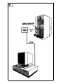
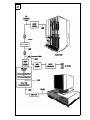
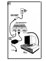
The processor module has two modular RS-232 jacks: one for
Station Message Detail Recording (SMDR) and the other for
system programming and maintenance via a personal computer
(see Figure 3).
A NiCad battery in the processor module provides backup
power for the real-time clock and nonvolatile RAM in case of
power failure or system shutdown. The battery provides RAM
data retention for 12 to 30 days. The trickle-charge circuit can
recharge the battery to 50 percent of capacity from a discharged
state in 48 hours. The minimum battery life is five years.
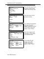
Line/Trunk and Station Modules
The line/trunk and station modules have jacks for connecting the
CO lines/trunks and the station lines to the CU. The station lines
connect to telephones and adjuncts.
Depending on the mode of operation chosen, the outside lines
that extend from the CO are called either trunks or lines. "Trunks"
is used for the Hybrid/PBX mode and in the phrase “tie trunks.”
“Lines” is used for Key or Behind Switch modes.
Control Unit 1-7
System Description
There are different types of lines/trunks for the different functions
of each mode. A Key or Behind Switch system can use
■
loop-start (LS) lines
■
tie trunks
■
a DS1 facility programmed for either T1 or Integrated
Services Digital Network Primary Rate Interface (ISDN-PRI)
operation
■
a ground-start (GS) line only when registered under the MF
FCC classification
A Hybrid/PBX system can use
■
loop-start trunks
■
ground-start trunks
■
tie trunks
■
direct inward dialing (DID) trunks
■
a DS1 facility programmed for either T1 or ISDN-PRI
operation
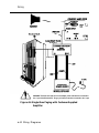
The names of modules consist of a number identifying the
number of lines/trunks and/or stations that can be connected to
the module, followed by the types of lines and/or telephones it
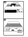
supports. For example, the 408 GS/LS module provides four line
jacks and eight station jacks and supports ground-start or loopstart lines.
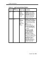
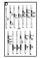
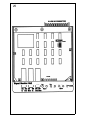
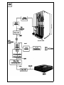
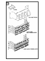
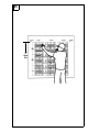
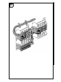
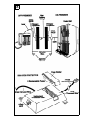
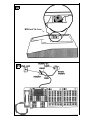
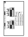
The system supports 13 types of line/trunk and station modules
(see Figure 4). Table 1-1 lists the specifications for each type of
module.
See Appendix A for wiring diagrams.
1-8 Control Unit
System Description
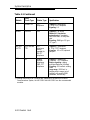
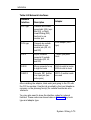
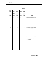
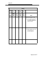
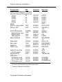
Table 1-1
Line/Trunk and Station Modules
Module
Line/
Trunk Type
008
008 MLX
Station Type
Specifications
N/A
Analog
multiline
telephone;
CMS; analog
data via a
modem
Capacity: 8 analog stations
Signaling: analog multiline
telephone protocol (40 kbps)
Loop range: 1000 feet inbuilding or in-range out-ofbuilding, with analog IROB
protectors, service only
N/A
MLX
telephone;
digital data
device
(such as
ISDN 7500B
Data
Module)
Capacity: 8 digital stations,
each with one or two endpoints
(each endpoint is assigned an
individual extension number),
including the following station
types:
■ digital voice only
■ digital voice with Voice
Announce to Busy feature
■ digital voice and digital data
(via the ISDN 7500B Data
Module)
■ digital voice and MFM
■ digital data only (ISDN
7500B Data Module)
Signaling: ISDN-BRI S/T
protocol (two 64-kbps
B channels, one 16-kbps
D channel) on a passive bus
Power: 4-VDC phantom power
to telephone; 48 VDC over a
separate pair (7-8) to an
operator DSS console
Loop range: 1000 feet, inbuilding and in-range out-ofbuilding, with MLX IROB
protectors, service only
Control Unit 1-9
System Description
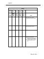
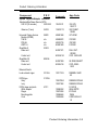
Table 1-1 Continued
Module
Line/
Trunk Type
008 OPT
N/A
Station Type
Specifications
On-premises
or offpremises
single-line
telephone
Capacity: 8 T/R stations* on
2-way voice transmission path
with support for telephones with
message-waiting LEDs; 2 TTRs
Notice to telephone company:
meets FCC Class C
Ringing current: 105-Vrms,
30-Hz sinusoidal ringing superimposed on -48 VDC; a ring
generator must be installed in
the power supply module of
each carrier that has a 008 OPT
module.
REN: ≥ 1.0 per port
Disconnect signal: 900 ms
(T/R short for answering
machines, G3 fax, etc.)
Switchhook flash detection:
300—1200 ms
Loop resistance: serves 2-wire
loops to 1300 ohms, including
stations
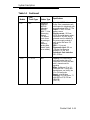
* The system software recognizes the OPT module as a 012 module; thus, the
overall station capacity is reduced by four stations for every OPT module.
1-10 Control Unit
System Description
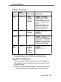
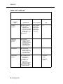
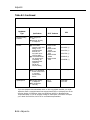
Table 1-1 Continued
Module
Line/
Trunk Type
012
1OOD
Station Type
Specifications
N/A
Single-line
telephone;
MERLIN
Attendant;
MERLIN
MAIL™ Voice
Messaging
System;
T/R adjunct
(such as an
answering or
a fax
machine);
analog data
device (such
as a modem)
Capacity: 12 T/R stations on
2-way voice transmission path
with support for telephones with
message-waiting LEDs; 2 TTRs
Power: 21-VDC, 600-ohm
battery source
Ringing current: 105-Vrms,
30-Hz sinusoidal ringing superimposed on -48 VDC; a ring
generator must be installed in
the power supply module of
each carrier that has a 012
module.
REN: ≥ 1.0 per port
Disconnect signal: 900 ms
(T/R short for answering
machines, G3 fax, etc.)
Switchhook flash detection:
300—1200 ms
T1 or PRI
N/A
Capacity: 24 lines/trunks for
voice and analog data or 23
lines/trunks for voice and data
with 1-channel used for
signaling
Mode: multiplexes 23 or 24
lines/trunks into 1 facility and
demultiplexes one facility into
23 or 24 lines/trunks
Speed: up to 64 kbps
Signaling: DS1 over 4-wire; T1
uses RBS or CCS; PRI has
ISDN-PRI
(23 B + D)
Control Unit 1-11
System Description
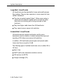
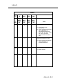
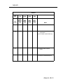
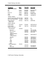
Table 1-1 Continued
Module
Line/
Trunk Type
Station Type
Specifications
400†
LS and TTR
PFT
telephone
Capacity: 4 lines/trunks,
4 TTRs, 1 PFT telephone
Signaling: LS
400EM
Tie trunk
N/A
Capacity: 4 tie trunks
Method of Completion:
automatic-start, immediatestart, wink-start, or delay-dialstart
Signaling: E&M type 1S, type
1C, type 5
400 GS/
LS/TTR
LS or GS and
TTR
PFT
telephone;
button
needed for
GS PFT
telephone
Capacity: 4 lines/trunks,
4 TTRs, 1 PFT telephone
Signaling: LS or GS, optioned
per port
408†
LS
Analog
multiline
telephone;
CMS; PFT
telephone
Capacity: 4 Iines/trunks,
8 stations, 1 PFT telephone
Station signaling: analog
multiline telephone (40 kbps)
Signaling: LS Iine/trunk: analog
voice
Loop range: 1000 feet, inbuilding and in-range out-ofbuilding, with analog IROB
protectors, service only
† Although these MERLIN II modules are supported in the MERLIN LEGEND
Communications System, the 400 GS/LS and 408 GS/LS are the recommended
modules.
1-12 Control Unit
System Description
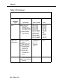
Table 1-1 Continued
Module
‡
Line/
Trunk Type
Station Type
Specifications
408
GS/LS
LS or GS
Analog
multiline
telephone;
CMS; PFT
telephone
Capacity: 4 Iines/trunks,
8 stations, 1 PFT telephone
Station signal: analog
multiline telephone (40 kbps)
Line/trunk signaling: LS or GS
line/trunk, optioned per port
voice
Loop range: 1000 feet, inbuilding and in-range out-ofbuilding, with analog IROB
protectors, service only
800‡
LS
PFT
telephone
Capacity: 8 lines/trunks, 2 PFT
telephones
Signaling: LS
800 DID
DID
N/A
Capacity: 8 Iines/trunks, 2 TTRs
Protocol: incoming calls only;
2-way (1-pair) fixed impedance
to DID trunks; no outgoing calls
Signaling: loop-reverse battery
wink-start or immediate-start;
accepts touch-tone dialing
800
GS/LS
LS or GS
PFT
telephone;
button
needed for
GS PFT
telephone
Capacity: 8 lines/trunks, 2 PFT
telephones
Signaling: LS or GS
Although this MERLIN II module is supported in the MERLIN LEGEND
Communications System, the 800 GS/LS is the recommended module.
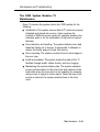
Loop-Start Lines/Trunks
LS Iines/trunks are the standard for home and small business
Key systems. They are less expensive in some areas but have
certain limitations:
■
They do not protect against "glare." (Glare occurs when a
person tries to make an outside call on a line/trunk at the
Control Unit 1-13
System Description
Loop-Start Lines/Trunks
LS lines/trunks are the standard for home and small business
Key systems. They are less expensive in some areas but have
certain limitations:
■
They do not protect against "glare." (Glare occurs when a
person tries to make an outside call on a line/trunk at the
same time an incoming call is being received on that
line/trunk.)
■
They have higher cable losses than GS lines/trunks
■
They cannot assure secure toll restriction.
Ground-Start Lines/Trunks
GS lines/trunks are outside lines/trunks used by some
businesses (such as hotels or motels) because the improved
signaling of GS allows more secure toll restriction.
In addition, GS lines/trunks prevent glare and provide cable
losses less than or equal to 4.5 dB.
The following types of outside lines/trunks come in either GS or
LS form:
■
basic lines
■
WATS (wide area telecommunications service)
■
800 service (In-WATS)
■
foreign exchange (FX)
1-14 Control Unit
System Description
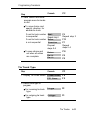
Tie Trunks
Tie trunks provide private communication between two systems.
Tie trunks “tie” the two systems together, making it seem that all
the telephones are on the same system. (See "Networking
Capabilities" in this chapter for more information on how tie
trunks connect to other systems.)
Tie trunks provide efficient communication between systems at
different locations. These locations can be different floors of the
same building, different buildings in the same campus, or
different cities or states.
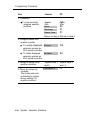
Tie trunks can be added to the system via the 400EM module.
The 400EM module has four ports that must be programmed
individually by selecting trunk options and setting the DIP (dual
in-line package) switches, located on the front of the module, for
different signaling modes and types (see Figure 72).
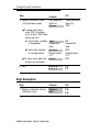
The following tie-trunk options need to be programmed:
■
Direction
■
■
Two-way (factory setting). Calls can be made in either
direction.
■
Outgoing only. Calls can be dialed but not received (no
ringing).
■
Incoming only. Calls can be received but not dialed (no
dialing).
Signaling Type can be any of the following types,
programmed via the 400EM module. The type of signal can
be set separately for incoming and outgoing calls; for
example, a tie trunk can be wink-start for incoming calls and
delay-dial-start for outgoing calls.
Control Unit 1-15
System Description
■
Wink-start (factory setting). The originating end of the tie
trunk transmits an off-hook signal and waits for the remote
end to send back a signal (a wink) indicating that it is
ready to receive dialing information.
■
Immediate-start. No start signal is necessary, and dialing
can begin immediately after the tie trunk is seized.
■
Delay-dial-start. The originating end of the tie trunk
transmits an off-hook signal and waits for the remote end
to send an off-hook signal followed by an on-hook signal.
■
Automatic-start. Incoming calls are routed directly to
another station without a start signal. In other words, when
you pick up the handset, the signal rings immediately at
the other end. This is also called an automatic-ringdown
tie trunk.
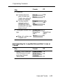
Wink-start, immediate-start, and delay-dial-start are also
called dial-repeating tie trunks.
■
■
E&M Signal
■
Type 1 standard (factory setting)
■
Type 1 compatible
■
Type 5
Dial Mode determines the incoming and outgoing dial.
modes:
■
rotary (factory setting)
■
touch-tone
Note: If the 400EM module is administered for touch-tone
dialing and there are no modules in the system that
provide touch-tone receivers (TTRs) (012, 008 OPT, 400,
400 GS/LS/TTR, or 800 DID), a 400 GS/LS/TTR module
must be installed.
1-16 Control Unit
System Description
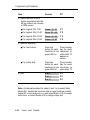
■
■
■
Dial Tone determines whether the system returns a dial tone
to the remote end of the line:
■
yes (factory setting)—a dial tone is sent to the remote end
■
no—a dial tone is not sent to the remote end
Answer Supervision Time sets a time limit in milliseconds
(ms) for the remote station to signal the calling station:
■
300 ms (factory setting)
■
20–4800 ms (increments of 20 ms)
Disconnect Time sets a time limit in milliseconds for the
release of the E or M lead:
■
300 ms (factory setting)
■
140–2400 ms (increments of 10 ms)
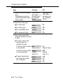
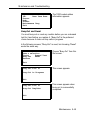
Direct Inward Dialing Trunks
Direct inward dialing (DID) trunks allow incoming calls to reach
specific individuals or facilities in the system without the
assistance of a system operator. DID trunks are available only in
the Hybrid/PBX mode. They are connected to the system on an
800 DID module.
With DID service, the customer reserves blocks of DID numbers
from the local telephone company. The DID number should
correspond to the extension number for an individual or a calling
group, or to the code for Remote Access or pool dial-out.
CAUTION:
DID numbers that correspond to pool dial-out codes (or
facility access codes) can be used to avoid toll restriction,
leading to toll abuse and/or fraud (see “Security of Your
System” under “Customer Support Information" in the front of
this book).
Control Unit 1-17
System Description
Because DID trunks allow calls to come directly to a telephone
extension, they cannot be pooled. The CO passes the necessary
digits to the system, which delivers the call directly to the dialed
extension.
The system can receive 1- to 4-digit extension numbers over the
DID trunks. The number of digits received on a specific DID
trunk is always the same for that trunk; however, different DID
trunks can receive different numbers of digits.
If the extension numbers used in the system are fewer than four
digits but the CO sends four, the system can be programmed to
ignore the leading digit(s). For example, if the DID number sent
by the CO is 2157, the extension numbers the system can
access are 57, 157, or 2157. System programming determines
the proper extension number to connect.
The system also can be programmed to match more digits than
are received from the CO. Additional leading digits are taken
from the 4-digit trunk number, as programmed. For example, if
the system is setup to match three digits and the CO sends only
two, programming determines which DID trunk number prefix to
add to complete the match and connect the call.
No routing of calls is made until the designated number of digits
is received. Incoming DID numbers that don’t match a valid
extension are either directed to a predesignated extension, such
as the system operator, or the system sends back a reorder tone
(fast busy).
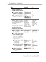
Options are assigned to blocks of DID trunks. A maximum of two
blocks of DID trunks is allowed. Each block can be configured to
match the system numbering plan. For example, the system
could have both 3- and 4-digit extension numbers. Trunk block 1
contains the options needed to reach the 3-digit numbers, and
trunk block 2 contains the options needed to reach the 4-digit
numbers (see Appendix K).
1-18 Control Unit
System Description
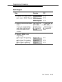
The options for each DID trunk group are as follows:
■
■
■
■
■
■
Type
■
wink-start (factory setting)
■
immediate-start
Expected Digits
■
3 (factory setting)
■
1–4
Delete Digits
■
0 (factory setting)
■
0–4
Add Digits
■
0 (factory setting)
■
1- to 4-digit number (1 to 9999)
SignaIing
■
rotary (factory setting)
■
touch-tone
Invalid Destination
■
backup position (factory setting)
■
return to fast busy
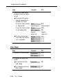
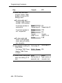
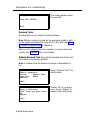
100D Module
The 100D module is the interface that connects a DS1 facility to
the system. It can be configured for T1 or Integrated Services
Digital Network Primary Rate Interface (ISDN-PRI) service (see
"DS1 Capabilities" later in this chapter).
Control Unit 1-19
System Description
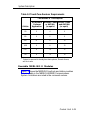
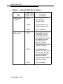
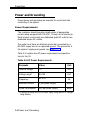
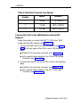
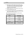
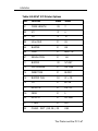
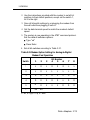
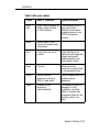
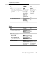
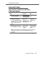
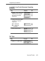
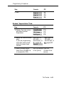
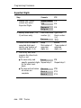
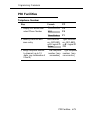
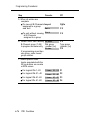
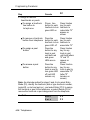
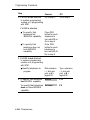
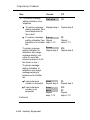
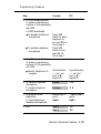
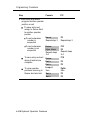
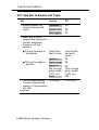
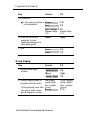
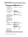
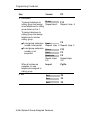
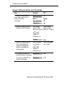
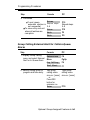
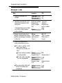
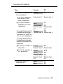
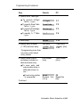
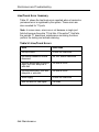
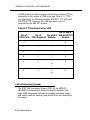
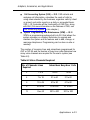
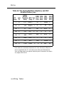
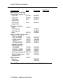
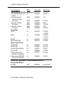
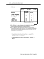
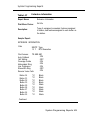
Touch-Tone Receivers
The 800 DID, 008 OPT, and 012 modules each provide two
TTRs. Normally these TTRs are sufficient to handle calls
originated on the 012 or 008 OPT module or received on the 800
DID module. However, additional TTRs maybe needed to
support the following services:
■
tie trunks and DS1 emulated tie trunks set for Dual-Tone
Multifrequency (DTMF) signaling
■
Remote Access
■
Account Code Entry
■
AUDIX Voice Power (AVP)—IS II or Integrated Voice Power
Automated Attendant (IVP AA)—IS II applications
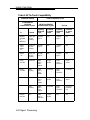
If more TTRs are needed to support these services, 400 or 400
GS/LS/TTR modules can be added (each module provides four
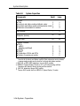
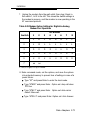
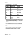
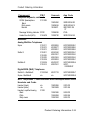
TTRs). Table 1-2 shows the estimated number of TTRs needed in
the system, depending on the call volume and the types of
services.
1-20 Control Unit
System Description
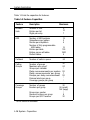
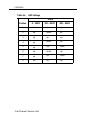
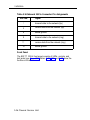
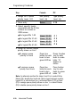
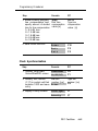
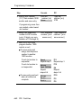
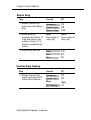
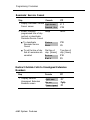
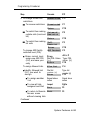
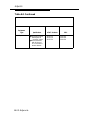
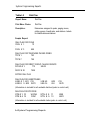
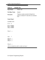
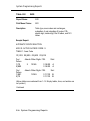
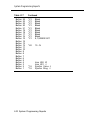
Table 1-2 Touch-Tone Receiver Requirements
Total Number of TTRs Required*
Calls/hr
No Account
Codes or
Applcation
Account Codes Account Codes
and AVP/AA
or AVP/AA
(or equiv)
(or equiv)
110
2
4
6
180
4
6
8
350
4
8
10
420
6
8
10
610
6
10
12
710
8
10
14
* System is assumed to already have basic phones, Remote Access,
and tie trunks.
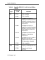
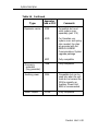
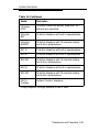
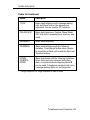
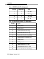
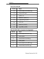
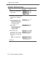
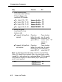
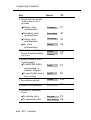
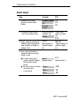
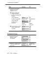
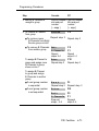
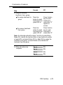
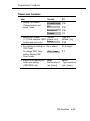
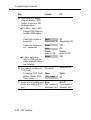
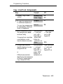
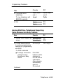
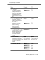
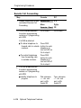
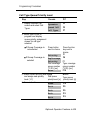
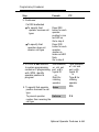
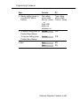
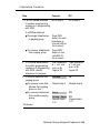
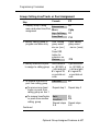
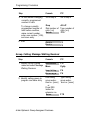
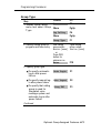
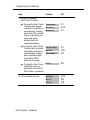
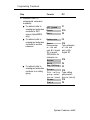
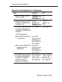
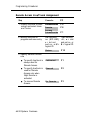
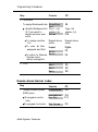
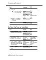
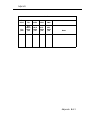
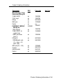
Reusable MERLIN® II Modules
Table 1-3 shows the MERLIN II line/trunk and station modules
that are usable in the MERLIN LEGEND Communications
System. Limitations are noted in the comments column.
Control Unit 1-21
System Description
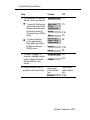
Table 1-3
Type
Reusable MERLIN II Line/Trunk and Station
Modules
Apparatus
Code
517A3
Fully compatible
517B3
Fully compatible
517A13
Compatible but does not
support the downlink disconnect
needed for voice-mail; does not
meet Megacom® transmission
requirements
517B13
Compatible but does not
support the downlink disconnect
needed for voice-mail; does not
meet Megacom transmission
requirements
517C13
Compatible but does not meet
Megacom transmission
requirements
517D13
Compatible but can be used for
Megacom only when the
customer does not have to meet
EIA transmission standards
517E13
Fully compatible
517A15
Outgoing Call Management only
517B15
Supports only tie-trunk
emulation
008
012
100D
Comments
1-22 Control Unit
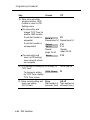
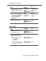
System Description
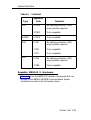
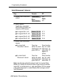
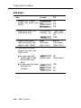
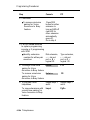
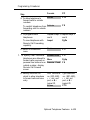
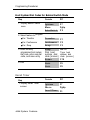
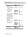
Table 1-3
Type
Continued
Apparatus
Code
Comments
517A12
No lightning protection; 146A
surge protector required
517B12
Fully compatible
400EM
517A14
Fully compatible
408
517A1
No lightning protection; 146A
surge protector required
517B1
Fully compatible
517C1
Fully compatible
517A4
No lightning protection; 146A
surge protector required
517B4
Fully compatible
400
800
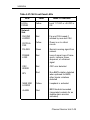
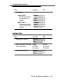
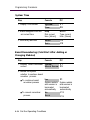
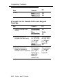
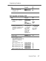
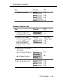
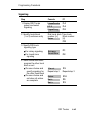
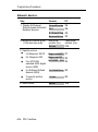
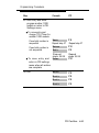
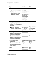
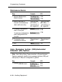
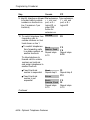
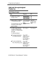
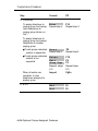
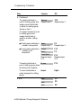
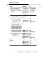
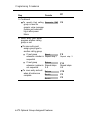
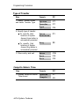
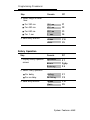
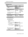
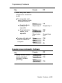
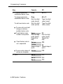
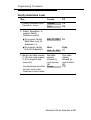
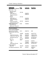
Reusable MERLIN II Hardware
Table 1-4 shows the MERLIN II hardware components that can
be used in the MERLIN LEGEND Communications System.
Limitations are noted in the Comments column.
Control Unit 1-23
System Description
Table 1-4
Reusable MERLIN II Hardware
Type
Power supply
module
Basic carrier
1-24 Control Unit
Apparatus
Code or PEC
Comments
391A
No surge protection;
147A protector
recommended
391AA
For Canadian use; no
auxiliary power jack
391A1
Fully compatible
403A
Compatible but must
order system cover
separately (part 16A);
required spring clips for
the system cover are
provided with the
MERLIN LEGEND
Communications System
upgrade package
403C
For Canadian use;
system cover and spring
clips needed; the clips
are provided with the
MERLIN LEGEND
Communications System
upgrade package
403E
Fully compatible
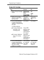
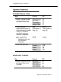
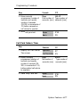
System Description
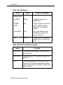
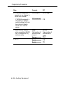
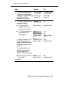
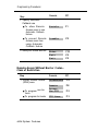
Table 1-4 Continued
Type
Apparatus
Code or PEC
Comments
403B
Compatible but must
order system cover
separately (part 17A)
403D
For Canadian use;
system cover and spring
clips needed; the clips
are provided with the
MERLIN LEGEND
Communications System
upgrade package
403F
Fully compatible
Frequency
generator
(ring generator)
129B
Fully compatible
Auxiliary power
335A
Compatible but can be
used only when the unit
loads do not exceed the
335A’s capacity an
Auxiliary Power Unit
9024 is recommended
Music coupler
61398
Fully compatible
Expansion carrier
Control Unit 1-25
System Description
Telephones and Consoles
Several different analog and single-line telephones work with the
system; however, the only digital telephones that work with the
system are the digital/ISDN (MLX) telephones.
WARNING
An analog or digital multiline telephone located in a different
building but within 1000 feet of the CU requires an IROB (inrange out-of-building) protector at each building entrance.
See Appendix C for ordering information on these telephones.
MLX Telephones
There are four new telephones in the MLX telephone line, all of
which support ISDN capabilities:
■
MLX-20L™ telephone
■
MLX-28D™ telephone
■
MLX-10D™ telephone
■
MLX-10™ telephone
Some features are common to all MLX telephones:
■
programmable line and feature buttons with two associated
lights (red and green)
Note: An MLX-20L telephone used as a QCC has no
programmable buttons.
■
dedicated feature buttons (four have a red or green light)
■
red message-waiting light
■
built-in speakerphone
■
volume control for speakerphone, handset, and ringer
1-26 Telephones and Consoles
System Description
■
user reference card tray with feature and programming codes
and directory lists
■
optional interns Multi-Function Module (MFM) to connect to
tip/ring (T/R) equipment and alerting devices (described in
Chapter 3)
Note: An MLX-20L telephone used as a QCC cannot have an
MFM in it.
■
two-position adjustable desk stand
■
four-pair modular line cord
MLX telephones with display have two additional features:
■
LCD display
■
display-associated keys
A list of features specific to each telephone model in the MLX
telephone family follows.
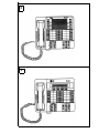
MLX-20L Telephone (see Figure 5)
■
can be used for system programming and as a DLC or a
QCC operator console
■
20 line and feature buttons
■
display (7 lines x 24 characters)
■
14 display-associated buttons
■
accommodates one or two Direct Station Selectors (DSSs)
MLX-28D Telephone (see Figure 6)
■
can be used as a DLC operator console
■
28 line and feature buttons
■
display (2 lines x 24 characters)
Telephones and Consoles 1-27
System Description
■
8 display-associated buttons
■
accommodates one or two Direct Station Selectors (DSSs)
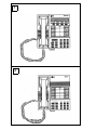
MLX-10D Telephone (see Figure 7)
■
10 line and feature buttons
■
desktop or wall-mount
■
display (2 lines x 24 characters)
■
8 display-associated buttons
MLX-10 Telephone (see Figure 8)
■
10 line and feature buttons
■
desktop or wall-mount
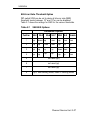
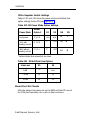
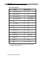
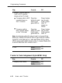
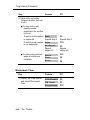
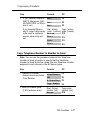
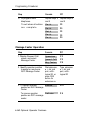
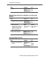
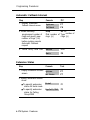
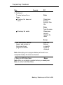
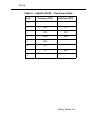
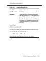
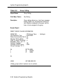
Analog Multiline Telephones
In addition to the MLX telephones, the analog multiline
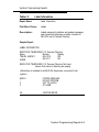
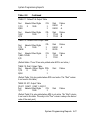
telephones in Table 1-5 can be connected to the system.
Table 1-5 Analog Multiline Telephones
Model
Description
5-button*
5-button telephone with membrane. No adjuncts
are supported with this telephone.
10-button*
10-button telephone with membrane
34-button*
34-button basic telephone with membrane
34-button
Deluxe*
Deluxe 34-button telephone with membrane
* Vintage telephone; no longer available for sale or lease
1-28 Telephones and Consoles
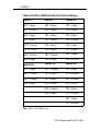
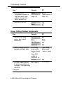
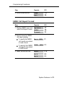
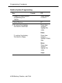
System Description
Table 1-5 Continued
Model
Description
10-button
HFAI*
10-button hands-free-answer telephone. No
adjuncts are supported.
34-button
BIS*
34-button telephone with built-in speakerphone
34-button
BIS/DIS*
34-button telephone with 16-character display
and built-in speakerphone
BIS-10
10-button telephone with built-in speakerphone
BIS-22
22-button telephone with built-in speakerphone
BIS-22D
22-button telephone with 16-character display
and built-in speakerphone
BIS-34
34-button telephone with built-in speakerphone
BIS-34D
34-button telephone with 16-character display
and built-in speakerphone
MLC-5
Cordless
Cordless 5-button telephone
* Vintage telephone; no longer available for sale or lease
Telephones and Consoles 1-29
System Description
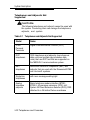
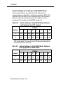
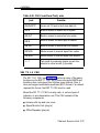
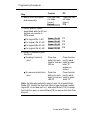
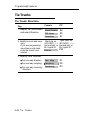
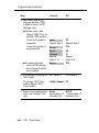
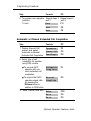
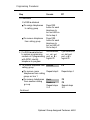
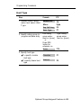
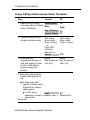
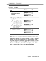
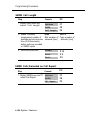
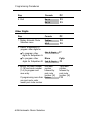
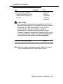
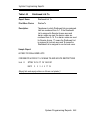
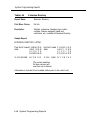
Single-Line Telephones
The system supports the single-line analog telephones listed in
Table 1-6.
Note: 2500MM or 500MM telephones should be used for PFT
telephones. If the telephones are to be connected to GS
lines/trunks, a GS button (KS 23566L1, PEC 31021 ) must be
added to each PFT station. If rotary lines/trunks are used, PFT
telephones must be rotary telephones.
Table 1-6
Single-Line Telephones
Model
Description
2500MMGB
Basic desk telephone
2554MMGJ
Basic wall telephone
2500YMGK
Basic desk telephone with message-waiting
light and Recall button. Recall button is used
instead of the switchhook for features that
require a switchhook flash, such as Transfer
and Hold.
2500SM
Basic desk telephone used with 4A
speakerphone
2514BMW
Basic desk telephone with built-in headset jack
2526BMG
Outdoor telephone used with weatherproof
enclosure
7101A*
Basic desk telephone with message-waiting
light and Recall and Disconnect buttons. No
adjuncts are supported.
* Vintage telephone; no longer available for sale or lease
1-30 Telephones and Consoles
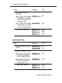
System Description
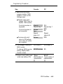
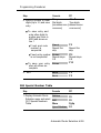
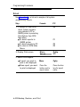
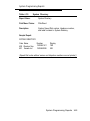
Table 1-6 Continued
Model
Description
7102A
Basic desk telephone with message-waiting
light and Recall button. No adjuncts are
supported. Can be used for PFT stations.
CS6402U01A*
Basic desk telephone, Feature Phone Model
420. Has built-in speakerphone, memory, and
redial.
2500MMGJ
Basic desk telephone
2500MMGK
Basic desk telephone with the following
limitation: Timed Recall button action (similar
to a switchhook flash) will invoke the Hold and
Transfer feature.
500MM
554BMPA
500SM
Basic telephones with the following limitations:
Since these sets are equipped with rotary
dials, no system features requiring ✱ and #
can be used. Telephones equipped with neon
message-waiting lights are not supported.
* Vintage telephone; no longer available for sale or lease.
Telephones and Consoles 1-31
System Description
Telephones and Adjuncts Not
Supported
CAUTION:
The following telephones and adjuncts cannot be used with
the system. Connecting them can damage the telephones,
adjuncts, and system.
Table 1-7
Telephones and Adjuncts Not Supported
Model
Notes
510D
Personal
Terminals
Digital Communications Protocol (DCP)
DCP
telephones
7400 telephones and adjuncts (asynchronous
data units and multiple asynchronous data
units) that use DCP and that are supported on
the MERLIN II communications system.
MET
telephones
Multibutton electronic telephones (MET) and
adjuncts that are used with the Dimension® PBX
and Horizon® systems.
Single-line
telephones
with neon message-waiting light
Analog
telephone
adjuncts
Basic telephone modem interface (BTMI);
BTMI-2; off-premises extension (OPX) unit;
System 25 Direct Extension Selector (DXS); DSS
attached to a 34-button Deluxe membrane
1-32 Telephones and Consoles
System Description
System Operator Consoles
System operator consoles are telephones that are programmed
for call handling and other operator duties.
Two configurations of operator consoles can be used—directline console (DLC) and queued call console (QCC). In a DLC
configuration, lines/trunks are assigned to individual buttons and
the console can have several calls ringing at the same time. In a
QCC configuration, incoming calls are held in a queue and calls
are directed to, a QCC as a position becomes available. Only one
call rings at a time.
The following telephones can function as DLCs:
■
MLX-20L telephone*
■
MLX-28D telephone*
■
MERLIN II System Display Console with built-in DSS
■
BIS-34D
■
■
BIS-34
BIS-22D
Note: In a Hybrid/PBX system, only the MLX-20L telephone can
function as a QCC.
DLCS are connected either to an analog station jack on a 008 or
408 analog multiline telephone module or to a digital station jack
on a 008 MLX module. QCCs must be connected to a digital
station jack on a 008 MLX module. The QCC system operator
console must be connected to the first jack on the first 008 MLX
module.
* One or two DSS adjuncts can be added to provide 50 or 100
additional extension buttons.
Telephones and Consoles 1-33
System Description
Adjuncts
Adjuncts are pieces of equipment that connect directly to the CU
or to a telephone through an adapter (see “Adapters” below).
Answering machines, credit card verification terminals, and
external alerts are examples of adjuncts. For more information on
adjuncts, see Appendix B.
Adapters
Adapters enable a proper connection of equipment or, in the
case of the channel service unit (CSU), of a DS1 facility to the
CSU. Some adapters connect directly to the CU (system
adapters) while others connect to telephones (telephone
adapters). See Chapters 3 and 6 for the installation procedures
for these adapters:
■
■
system adapters
■
ESF T1 CSU
■
551 T1 L1 CSU
■
Universal Paging Access Module (UPAM)
telephone adapters
■
Multi-Function Module (MFM) for digital telephones
■
General Purpose Adapter (GPA) for analog telephones
■
ISDN 7500B Data Module for connecting digital data
equipment either directly to the CU or to an MLX
telephone (for simultaneous voice and data transmission)
■
■
modem for connecting digital equipment, such as a
personal computer (PC), to a tip/ring (T/R) interface
Supplemental Alert Adapter (SAA) for connecting alerts
(such as horns or strobes) to an analog multiline telephone
1-34 Adjuncts and Adapters
System Description
System Capacities
The system comes in two sizes, large and small. The large
system supports up to 80 central office (CO) lines/trunks and 144
stations, such as telephones and fax machines, and the small
system supports up to 24 CO lines/trunks and 56 stations. The
size of the system is determined by its memory capacity—that is,
the processor module (including the feature module) located in
the control unit (CU).
The large system has a total capacity of 224 jacks (80 CO
lines/trunks plus 144 stations); however, each MLX module
station jack supports two logical endpoints (station devices that
can operate simultaneously and independently). For example, an
MLX telephone with a Multi-Function Module (MFM) plugs into
only one station jack, but the jack supports the telephone and
the equipment connected to the MFM (such as a fax machine or
an answering machine).
In a similar way, although the 100D module has only one jack, it
can serve up to 24 endpoints (emulated lines/trunks or ISDN-PRI
lines/trunks).
Thus, the large system can be configured to connect up to 80
lines/trunks and 255 station endpoints, a total of 335 endpoints.
Note: The system has a time-slot capacity of 216. If more than
216 endpoints are in use at the same time, blocking can occur.
Table 1-8 lists the capacities of the system’s hardware and
software components for both small and large systems.
System Capacities 1-35
System Description
Table 1-8
System Capacities
Components
Small
Carriers*
3
Total
5
■ Line/trunk and station module slots/basic carrier
■ Line/trunk and station module slots/expansion carrier 6
17
■ Maximum slots available for modules
■
Large
3
5
6
17
DS1 Modules
1
3
Endpoints (devices)
56
255
Lines/Trunks
24
80
Operator Consoles
DLCs:
■ MLX†
■ Analog multiline‡
■ QCCs§
■ DSSs**
■ Combination of DLCs and QCCs
■ Number of consoles per module
6
8
4
12
8
2
8
8
4
16
8
2
■
* The basic carrier contains a power supply module, processor module, and
five slots for line/trunk and station modules. Each expansion carrier contains
a power supply module and six slots for Iine/trunk and station modules.
† MLX-20L or MLX-28D telephone, two per MLX module
‡ MERLIN II System Display Console or 34- or 22-button analog multiline
telephone with display; two per analog multiline module
§ MLX-20L telephone; two per MLX module
** Two per MLX module (built into MERLIN II System Display Console)
1-36 System Capacities
System Description
Table 1-8
Continued
Small
Large
Ports (not achievable simultaneously)
■ Total (lines/trunks plus stations)
■ Voice and data stations
■ Voice Announce to Busy
■ Voice-mail interface
■ Data via ISDN 7500B Data Module
■ Paging
■ Delay announcements
80
56
28
20*
24
3
32
224
144
127
20*
127
3
32
System programming equipment†
MLX-20L
■ RS-232 jack (for connection of PC with SPM)
■ Modem
1
1
1
1
1
1
Components
■
Telephones
Single-line
■ Analog multiline
■ Without Voice Announce to Busy
■ Without Voice Announce to Busy
■ MLX-20L
■ MLX with ISDN 7500B Data Module or MFM
■ Power failure transfers
56
144
56
28
16‡
24
6
136
127
481‡
127
20
Two-party conversations
40
108
Traffic (CCS/hr/station)**
7.0
6.0
1
1
■
Voice-mail systems
—
* Although system software supports up to 24 voice-mail interface (VMl) ports,
all the VMI ports must be in the same calling group, and the maximum
number of stations in a calling group is 20.
† Remote access overrides on-site programming except during backup or
restore
‡ Total includes the MLX-20L telephone used for system programming
§ One per four GS/LS line/trunk jacks
** Assuming 20 percent internal traffic
System Capacities 1-37
System Description
Table 1-9 lists the capacities for features.
Table 1-9 Feature Capacities
Maximum
Feature
Description
Allowed
Lists
Number of lists
Entries per list
Digits per entry
8
10
7
ARS
Number of ARS patterns
Subpatterns per pattern
Routes per subpattern
Number of fully programmable
ARS tables
Entries per table
Entries across all tables
Default tables
18
2
6
16
100
1600
4
64
Callback
Number of calls in queue
Calling
Groups
32
Number of groups
20
Members per group*
1
Groups per member
Delay announcements per system 32
Delay announcements per group 1
Groups per delay announcement 32
1
External alerts per group
1
Coverage groups per group
Coverage
Groups
Number of groups
Senders per group
Groups per sender
Receiver buttons per group
Groups per QCC receiver
* QCCs cannot be members.
1-38 System Capacities
30
56 (small)
144 (large)
1
8
30
System Description
Table 1-9 Continued
Feature
Description
Data Hunt
Groups
Number of groups
Members per group
Groups per member
DID
Number of blocks
Number of trunks
Directories
System Directory
■ Number per system
■ Listings per directory
Maximum
32
20
1
2
24 (small)
80 (large)
1
40 (small)
130 (large)
Extension Directory
■ Number per system
■ Listings per directory
1
56 (small)
144 (large)
Personal Directory
■ Number per system
■
16 (small)
48 (large)
50
Listings per directory
Disallowed
Lists
Number of lists
Entries per list
Digits per entry
8
10
11
Fax
Number of fax machines
16*
Night
Service
Groups
Members per group
Groups per member
Emergency Allowed List entries
8
56 (small)
144 (large)
8
10
* System can support more than 16 fax machines, but those machines in
excess of 16 cannot use the fax message-waiting feature.
System Capacities 1-39
System Description
Table 1-9 Continued
Category
Description
Park Codes
Number of codes
Personal Lines Number of station endpoints
Maximum
8
56 (small)
64 (large)
Personal
Speed Dial
Numbers
Number of entries per telephone 24
880 (small)
Number of entries per system
1200 (large)
28
Digits per entry
Pickup
Number of groups
Members per group
Groups per member
Number of pools
Pools
(trunk groups) Number of trunks in a pool
Pool Buttons
Number of station endpoints
Remote
Access
Number of barrier codes
Digits per code
30
15
1
11
24 (small)
80 (large)
56 (small)
64 (large)
16
4
Shared System Number of shared buttons per SA 16
Access Buttons
System
Speed Dial
Number of entries per system
(up to 40 digits each)
1-40 System Capacities
40 (small)
130 (large)
System Description
Data Capabilities
The system can provide data connections between two digital
data modules (ISDN 7500B Data Modules), between two analog
modems, or between an analog modem and a digital data
module. The system provides access to an in-house host
computer or to a data station on a network.
Data facilities include
■
digital data endpoints—RS-232 interfaces via ISDN 7500B
Data Modules
■
analog data endpoints—tip/ring modem interfaces
■
local host computer and workstation on local area network
(LAN) access (only via an RS-232 interface)
■
DS1 facility interface (analog data via T1 or ISDN-PRI, or
digital data via ISDN-PRI)
Data Capabilities 1-41
System Description
Networking Capabilities
The system can connect to another system via the two CUs or
via the tie trunks.
Control Unit to Control Unit
This system’s CU can connect to another system’s CU in three
ways:
■
from an off-premises telephone (OPT) line to an LS line/trunk
(or vice versa) via analog facilities
■
via an analog tie trunk (400EM module)
■
via a digital tie trunk using emulated E&M in the T1 mode on a
100D module. A back-to-back connection from one DS1
facility to the other can be used when the total cable distance
is fewer than 1300 feet.
OPT/LS Connection
A 008 OPT module on system A’s CU can be connected to an LS
port on system B’s CU. This enables the user on system B to
access all the stations and facilities on system A. If system B has
Remote Access, the user on system A can directly access
stations and facilities on system B without operator intervention.
Conversely, an LS port on system A can be connected to an OPT
port on system B.
Note: If the systems are on the same premises, the connection
can be made to any T/R port.
1-42 Networking Capabilities
System Description
With the OPT/LS connection, glare is more frequent as the
volume of calls increases. (Glare occurs when a user tries to
make an outside call on a line/trunk at the same time an
incoming call is being received on that line/trunk.) In addition, if
system B (the LS interface) does not have Remote Access, only
the station(s) assigned to the LS facility on system B can be
accessed by system A.
Analog Tie-Trunk Connection
In an analog tie-trunk connection, the system A’s 400EM module
is connected to system B’s CU. On premises, this module can be
connected directly to system B if system B has similar tie-trunk
facilities.
For off-premises connection, the 400EM module can be
connected via the telephone company’s facilities to system B.
The analog tie-trunk connection can be programmed for two-way
traffic or for one-way traffic (incoming or outgoing). The one-way
mode prevents blocked calls caused by glare.
Digital Tie-Trunk Connection
The digital tie-trunk connection joins the DS1 facility (the 100D
module) on system A to system B’s DS1 facility. If system B is on
premises, the connection is back-to-back. To reach a remote
system, the DS1 facility connects via a channel service unit
(CSU) to the telephone company’s facilities.
Networking Capabilities 1-43
System Description
Tie-Trunk Networks
The following tie-trunk networks can be used with the system.
Nontandem
The nontandem network is used primarily to connect station lines
at both ends; it does not connect to another tie trunk (see
Figure 9).
Tandem
The tandem network has a station on one system connected to a
station on a third system via a tie-trunk connection in a second
system. The tandem network can also be used to connect to an
external facility in the third system, but the grade of service will
be fair to poor if one or both tie trunks are analog (see Figure 9).
Intertandem
The intertandem network has a tandem tie trunk connected to tie
trunks at both ends. It is not recommended for analog tie trunks
(see Figure 9).
1-44 Networking Capabilities
System Description
Functional Units
The functional units are the processor module, which controls the
operation of the system and its features; the line/trunk and station
modules, which connect the central office (CO) lines/trunks to
the stations; the power supply module, which supplies power to
the control unit; and the carrier with its backplane assembly,
which contains the input/output (I/O) bus and the time-division
multiplex (TDM) bus. All the modules are electrically connected
to the backplane, which provides common circuitry for the I/O
bus, the TDM bus, and power distribution. (See Figure 10 for a
functional block diagram of the system architecture.)
The processor module is connected to intelligent ports on the
line/trunk and station modules, through the I/O bus, by the digital
switch element (DSE) on each line/trunk and station module. The
TDM bus also is connected to the DSE of each line/trunk and
station module. The two busses are described below:
■
Input/Output Bus. The I/O bus contains a 16-bit address bus
and an 8-bit data bus. The address bus selects the module
that receives instructions from the 68000 microprocessor in
the processor module. The microprocessor provides
instructions to the port processors and DSEs through the 8-bit
data bus.
■
Time-Division Multiplex Bus. The TDM bus connects the
DSEs to allow voice or data to flow in and out of the system.
The TDM bus is parallel, 8 bits wide, and runs at 2.048 MHz
(256 time slots x 8 kHz = 2.048 MHz). Each TDM cycle has
256 time slots for voice, data, tones, and clocks. The frame
repetition rate is 8 kHz, providing a 64-kbps channel on each
time slot (8-bit bus x 8 kHz = 64 kbps).
Functional Units 1-45
System Description
The built-in data modem connects to the TDM bus; this
permits access from a local or remote PC or workstation
equipped with a 1200-bps modem. The TDM bus connects
with the built-in diagnostics that enable the processor to read
and write to dedicated TDM test slots.
Voice signals on the TDM bus are encoded in Mu-Law 255
pulse code modulation (PCM) format for domestic use. The
system provides a circuit-switched connection for
transmission of digital data signals up to 64 kbps. See “Signal
Processing” on the next page.
1-46 Functional Units
System Description
Signal Processing
Because the system is internally a digital system that must
interact with both analog and digital devices, it must accurately
translate analog signals. Doing this involves signal conversion,
quantizing, commanding, and switching.
Signal Conversion
The first step in analog-to-digital (A/D) conversion is to sample
the analog signal and convert the signal into a series of
amplitude steps. This is called pulse amplitude modulation
(PAM).
PAM samples the height of the analog waveform 8000 times per
second, or more than twice the frequency of the input signal
bandwidth (for analog voice the bandwidth is 3300 Hz). Because
the analog signal is sampled at more than twice its bandwidth,
both the amplitude and frequency content of the original analog
signal are preserved. The amplitude of each PAM sample is then
digitally encoded and transmitted by using a process called
pulse code modulation (PCM).
PCM uses PAM as its starting point but goes further by digitizing
the PAM signal for transmission via the digital switch. PCM
converts the height of each PAM pulse to an 8-bit digital signal
for transmission.
PCM digitizes the PAM information by comparing each PAM
sample to a point on a chart. Each point has a distinct 8-digit
binary code. Therefore, it is the binary code (digital), not the
amplitude pulse (analog), that is transmitted in PCM. At the
destination, the PAM signal is reconstructed from the PCM signal
via a digital-to-analog (D/A) converter. The D/A converter also
completes the reconstruction of the analog signal from the
stream of PAM signals.
Signal Processing 1-47
System Description
The digitally encoded signals are routed from one interface port
to another interface port by assigning source and destination to
specific time slots on the TDM bus. In this way, signals can be
transmitted to one or several destinations and reconstructed at
the original amplitude. The result is no signal loss during
switching and transmission from one point to another.
Quantizing
The process of converting PAM samples into discrete PCM
values is called quantizing. In the case of voice-grade signals,
eight bits are commonly used to encode one PAM sample.
Quantizing with eight bits allows 256 unique values to represent
the range of amplitudes in the analog signal being sampled.
Quantizing causes distortion due in part to the “rounding off” of
PAM samples into discrete PCM values. This distortion can be
minimized by increasing the number of bits used to encode each
PAM sample or by increasing the sampling rate. Using 8-bit
coded samples taken at an 8-kHz rate results in toll-grade
transmission quality.
Companding
Distortion also occurs in quantizing because equal consideration
is given to all amplitude levels. Linear quantizing divides the
amplitude range into equal segments, which results in
unnecessary quality at levels where voice signals are unlikely to
occur and not enough quality where they do occur. Commanding
eliminates this distortion by using a nonlinear scale that has
smaller divisions and more accuracy in areas of the scale where
voice signals are most likely to occur.
1-48 Signal Processing
System Description
Mu-Law 255
Mu-Law 255 is a commanding scheme that uses a compression
ratio compatible with modern channel bank equipment. The
scale is divided into 16 intervals, with each interval having 16
levels. Therefore, the scale has 256 discrete values. But since
Mu-Law 255 has a negative and a positive zero, it really has only
255 discrete values. This commanding scheme is used in the
United States and Japan.
Digital Switching
The TDM bus allows many users to communicate over a
common electrical connection because it is physically distributed
across the backplane of the CU and connects all line/trunk and
station modules.
The TDM bus has specific time slots for various functions. For
example, during a conversation between station A and station B,
a time slot is resewed for station A to transmit on and for station
B to receive on. An analog station can transmit on time slot 150
and receive on time slot 160. Because the TDM bus cycles 8000
times per second, the conversation is continuous.
The TDM bus carries tones and control signals to stations via
time slots 0 to 39. Unlike other bus configurations, the stations on
the TDM bus receive all transmissions. If a station is not
assigned to any of the time slots, the station ignores the data.
The digital switch element (DSE) is a digital switch for voice and
data. It also performs the operations for commanding schemes
such as Mu-Law and A-Law. Each module has a DSE to interface
codecs or digital transceivers to the TDM bus. The actual digital
switching occurs when the DSE is programmed by the system
I/O bus to transmit data on or receive data from the TDM bus in
specific time slots. For example, the digital station can send data
on time slot 200 and receive data on time slot 220.
Signal Processing 1-49
System Description
This process also involves time slot interchanging so that an
available slot in the TDM cycle can be filled with a transmit or
receive slot. The DSE allows up to 16 time slots to be
conference and sent out to a single station port.
Tie-Trunk Signaling
Tie trunks transmit via three different signaling formats, each
made up of a specific mode and a specific type.
The DIP switches on the 400EM module select the signaling
modes needed for tie-trunk transmission (see Figure 72); the
signaling type is selected during system programming.
Signaling Modes
There are two signaling modes:
■
Simplex mode. Two signaling leads superimposed onto the
analog transmission leads provide a 2-pair wire interface for
connecting two local systems at minimal cost.
■
E&M mode. This is a standard interface. The E&M signaling
leads are isolated from the transmission leads, requiring a
3-pair wire interface.
In the simplex mode, protective resistance is always included in
the circuit. The E&M mode can be either protected or
unprotected from high-voltage transients or fluctuations. In the
protected mode, a resistance is added to the leads to reduce
current peaks. The protected mode is used when there is no
network interface to protect the circuit from outside interference.
1-50 Signal Processing
System Description
The unprotected mode must be used for an E&M type 1
standard interface (see below) to meet the specified voltagedrop criteria. This mode is used when there is a network
interface.
CAUTION:
The protected mode must be used whenever the E&M leads
extend out-of-building and are not connected to the network
interface.
Signaling Types
Three different signaling types combine with the signaling
modes. Together these create the proper signaling format for
each system.
■
Type 1 standard. This is the factory-set type, which is used
to connect two systems through two intermediate COs. The
switches must be set for E&M mode.
■
Type 1 compatible. This type is used to connect directly
without intermediate COs. One system is set to type 1
standard, the other to type 1 compatible. The switches must
be set for E&M mode.
■
Type 5 simplex. This type is used to connect similar systems
or systems with compatible signaling that are Iocated in the
same building or on the same business campus.
The choice of a tie-trunk signaling format depends on the
particular application and the two systems being connected,
including whether or not the tie-trunk signals pass through CO
lines or over customer-owned cable. Table 1-10 shows how to
determine tie-trunk compatibility between the MERLIN LEGEND
Communications System and other systems.
Signal Processing 1-51
System Description
Table 1-10 Tie-Trunk Compatibility
Preferred Signaling Format
Installation Situation
From MERLIN
LEGEND
Communications System
MERLIN LEGEND
Communications System
To
Location
Signaling
Mode and
Type
Protected
or Unprotected
Signaling
Mode and
Type
Protected
or Unprotected
MERLIN
LEGEND
or
MERLIN II
Same site
or interbuilding
Simplex;
type 5
N/A
Simplex;
type 5
N/A
System
25 or
System
75
Same site
or interbuilding
Simplex;
type 5
N/A
Simplex;
type 5
N/A
System
85
Sane site
or interbuilding
Simplex;
type 5
N/A
Simplex;
type 5
N/A
Dimension PBX
Same site
E&M;
type 1;
compatible
Unprotected
E&M;
type 1;
standard
Unprotected
Dimension PBX
lnterbuilding
E&M;
type 1;
compatible
Protected
E&M;
type 1;
standard
Protected
Other
Same site
E&M;
type 1;
compatible
Unprotected
E&M;
type 1;
standard
Unprotected
Other
lnterbuilding
E&M;
type 1;
compatible
Protected
E&M;
type 1;
standard
Requires a
protection
unit
Network
Interface
N/A
E&M;
type 1;
standard
Unprotected
N/A
N/A
1-52 Signal Processing
Far End
System Description
DS1 Capabilities
A Digital Signal One (DS1) facility is a transmission system that
transports digital signals in the DS1 format. The interface that
allows the connection of DS1 facilities to the system is the 100D
module. Through this module voice and data calls can be placed
on or received by a DS1 facility.
Twenty-four Digital Signal Zero (DS0) channels, each operating
at 64 kbps, plus framing bits, are multiplexed, forming a DS1
signal of 1.544 Mbps. Each DS0 channel within the DS1 signal
corresponds to a logical endpoint. Even though there is only one
physical jack, the 100D module supports up to 24 logical
endpoints or ports (one for each channel).
In DS1 format, calls to other digital PBXs or COs remain digital,
and signals do not need to be converted to analog for
acceptance by the connecting trunk. In addition, the 100D
module can be configured to work with T1 or Integrated Services
Digital Network Primary Rate Interface (ISDN-PRI) service.
To connect the 100D module to an outside DS1 facility, a
channel service unit (CSU) is used. The CSU regulates the
transmission into and out of the 100D module so that the module
matches the transmission of the outside facility.
Both ends of the DS1 facility must be able to “speak the same
language.” To ensure this, the following options are set during
system programming to match the transmission of the outside DS1
facility:
■
type of service (T1 or ISDN-PRI)
■
framing format
■
line coding
■
line compensation
DS1 Capabilities 1-53
System Description
■
clock synchronization
■
signaling mode (for T1 service only)
The appropriate setting for each option is determined by the
transmission facility to which the module is connected. Each
option is discussed below.
Type of Service
The system supports two types of service for DS1 facilities: T1
and ISDN-PRI. The 100D module can be programmed to operate
in either type of service. T1 service transmits and receives voice
and analog data; ISDN-PRI transmits and receives voice and
analog and digital data.
The following AT&T Switched Network (ASN) services are
provided through a T1 or ISDN-PRI line/trunk:
■
Megacom WATS service for domestic long-distance outward
voice calls; ISDN-PRI does not support international dialing
for Megacom WATS service.
■
Megacom 800 service for domestic toll-free incoming voice
calls. T1 service supports Megacom 800 with or without
Dialed Number Identification Service (DNIS), while ISDN-PRI
supports it only without DNIS. Also, ISDN-PRI does not
support international dialing for Megacom 800 service.
■
Software Defined Network (SDN) for voice and circuitswitched data calls (up to 56 kbps). SDN lets businesses use
portions of the ASN in concert with their dedicated private line
networks. However, the system does not support “uniform
dialing plan,” which is necessary for complete integration with
SDN. Also, ISDN-PRI service does not support international
dialing for SDN.
■
MultiQuest® service for domestic toll incoming voice calls
(900 number). T1 supports MultiQuest service with or without
DNIS, while ISDN-PRI supports it only without DNIS.
1-54
DS1 Capabilities
System Description
Any combination of these ASN services can be used in T1 or
ISDN-PRI.
In addition to these ASN services, T1 also supports Shared
Access for Switched Services (SASS). SASS allows both
Megacom WATS and Megacom 800 services to be offered over
the same line/trunk facilities, eliminating the need to have
separate incoming and outgoing Iine/trunk groups.
Like T1, ISDN-PRI also supports Megacom WATS and Megacom
800 services on a shared line/trunk, but only on a call-by-call
basis. Besides this, ISDN-PRI provides Accunet® Switched
Digital Service for 56-kbps, 64-kbps restricted, and 64-kbps
clear circuit-switched data calls. However, Accunet Switched
Digital Service is not supported for international dialing.
T1
T1 is the factory setting and is selected for the DS1 facility to
allow each of the 24 channels to be programmed to emulate tie,
LS, or GS lines/trunks in any combination. This means that a
single 100D module can take the place of 24 regular outside
lines.
If common-channel signaling is selected, 23 channels are
available for emulation and the 24th channel carries formatting
signals.
ISDN-PRI
ISDN-PRI is a standard format for ISDN service. Some of the
benefits of ISDN-PRI service are
■
Speed. Data calls to outside destinations can be established
on the same B channels used for voice calls if the service
allows. Modems and dedicated, conditioned lines/trunks are
not needed.
DS1 Capabilities 1-55
System Description
■
AT&T’s INFO2 automatic number identification (ANI)
service. Customers who subscribe to this service can identify
an incoming call on an lSDN-PRl line/trunk by either
telephone number or billing number.
Note: The availability of the caller identification information
may be limited by local-serving (caller’s) jurisdiction,
availability, or CO equipment.
■
Dynamic B-channel assignment. An individual B channel
can be removed from service without blocking calls to or from
any other B channels.
■
Improved toll restriction. The ways that toll restriction can
be bypassed are limited on ISDN-PRI Iines/trunks.
■
Reliable indication of far-end disconnect.
■
Improved SMDR reports. Call timing for SMDR reports is
improved since lengths of times recorded are closer to the
actual billed duration.
Framing Format
To identify the DS0 channels, the DS1 signal is segmented into
blocks of 193 bits, called frames. A frame consists of 24 eight-bit
words (one for each channel) plus a framing bit at the beginning
of each frame: 24 words x 8 bits = 192 bits. Thus, a framing bit
appears in every 193rd bit position of the 1.544-Mbps DS1
signal.
Frames repeat at a rate of 8000 per second, with each frame
repeating DS0 channels 1 through 24 sequentially.
Two methods of framing can be used by a 100D module, but the
framing format chosen must match the framing at the far end:
■
D4 Framing Format. The system is factory set for the most
common framing format, D4 framing. A D4 frame consists of
24 eight-bit time slots and one framing bit. To synchronize the
1-56 DS1 Capabilities
System Description
signals, the receiving equipment uses the framing information
to identify the start of each frame and to identify which frames
contain signaling information. The framing information repeats
once every 12 frames; these 12 frames form the D4
superframe. This framing format is used by most DS1
equipment.
■
ESF Framing Format. The extended superframe (ESF)
format extends the 12-frame D4 superframe to a 24-frame
superframe, hence its name. The 24 framing bits include a
cyclic redundancy check (CRC) for the entire extended
superframe and a facility data link for maintenance. The ESF
can detect more errors than D4 framing; however, ESF is not
used universally by DS1 equipment.
Line Coding
The DS1 signal consists of a continuous bit stream of ones and
zeros, encoded into bipolar pulses for transmission. Only the
ones create a pulse; the zeros represent the absence of a pulse.
The pulses of the ones alternate between positive and negative.
This type of line coding is called bipolar or alternate mark
inversion (AMI). The line-coding formats guarantee that the
"ones-density" requirement is met to achieve clock recovery.
To meet the ones-density requirement, either zero code
suppression (ZCS) or bipolar 8 zero substitution (B8ZS) line
coding is used. The factory-set line coding is ZCS.
ZCS
ZCS line coding monitors each DS0 channel and prevents
strings of eight or more zeros. Upon detecting eight consecutive
zeros in a channel octet, ZCS line coding forcibly changes the
seventh zero (second least significant bit) to a one.
With ZCS line coding, any bit that is overwritten has no noticeable
effect on voice and voice-grade data. However, the ZCS linecoding format can cause errors in digital data transmission.
DS1 Capabilities 1-57
System Description
B8ZS
B8ZS line coding encodes an all-zero channel octet into a unique
binary sequence with a “bipolar violation” in bit positions 4 and 7.
Normally, for bipolar (AMI) transmission, ones are encoded
alternately as a positive then negative, or negative then positive,
pulse. If two positive or two negative pulses are received in
succession, a bipolar violation occurs.
Ordinarily bipolar violations are caused by noise hits on the
signal. However, B8ZS line coding allows the 8-bit strings to be
detected at the receiving end and converted back into the
original sequence.
B8ZS line coding is preferred over ZCS because it does not
cause errors in data transmission.
B8ZS violations are passed by the ESF T1 CSU but not by other
CSUs. The CSU is a hardware component needed when two
endpoints are located in different buildings or when the distance
between the two endpoints makes office or line repeaters
necessary. The CSU is located on the customer’s premises and
is used to connect the system to DS1 network facilities (see
“Install the Channel Service Unit” in Chapter 3, “Installation”).
Line Compensation
Line compensation adjusts for the amount of cable loss in
decibels (dBs), based on the length of cable between the 100D
module and the CSU or other far-end connection point. The
factory setting is a value of 1, which allows a maximum loss of
0.6 dB. The other possible settings are shown in Table 1-11.
1-58 DS1 Capabilities
System Description
Table 1-11 Line Compensation Settings
Cable Feet
Setting
dB Loss
1
-0.6
0-133
2
-1.2
133-266
3
-1.8
266-399
4
-2.4
399-533
5
-3.0
533-655
Clock Synchronization
Clock synchronization is an arrangement where digital facilities
operate from a common clock. Whenever digital signals are
transmitted over a communications link, the receiving end must
be synchronized with the transmitting end to receive the digital
signals.
The system synchronizes itself to the network by extracting the
timing signal from the incoming digital stream. If the system has
more than one 100D module, the module that provides the
primary synchronization for the other 100D modules and for the
TDM bus must be identified during system programming. The
factory setting is the first 100D module in the carrier. This can be
changed to the second or third module.
Backup synchronization in the event of a maintenance failure can
be provided by programming the second and third installed
modules as secondary and tertiary synchronization.
DS1 Capabilities 1-59
System Description
In addition, the source of synchronization can be factory set to
“loop clock reference source” (the clock is synchronized to the
external endpoint) or set to “local clock reference source” (the
clock is free running). This setting must be made for the primary,
secondary, and tertiary synchronization modules.
Signaling Mode
Signaling is the process of communicating channel-state
information (such as dialing) from endpoint to endpoint. Two
types of signaling can be used in T1 transmission: robbed-bit
signaling (RBS) and common-channel signaling (CCS).
Choosing a signaling mode pertains only to T1 service; ISDN-PRI
always uses common-channel signaling (23 B channels and 1
D channel).
Robbed-Bit Signaling
RBS replaces ("robs") the least significant bit of every sixth frame
of each DS0 channel with signaling information. (RBS is also
called in-band signaling, since signaling information is
embedded in the least significant bit of every sixth 8-bit word.)
RBS is appropriate for voice and voice-grade data (up to
1200 baud), but facilities using RBS cannot accurately transmit
digital data because digital data uses high-speed data rates,
such as 64 kbps. Therefore, the channel is limited to voice and
analog voice-band data applications.
1-60 DS1 Capabilities
System Description
Common-Channel Signaling
CCS is an out-of-band signaling format that places the signaling
bits for channels 1 through 23 into the 8-bit word of the 24th
channel. This restricts DS1from using the 24th channel for voice
or data transmissions.
D4 framing does not preclude the use of CCS, but CCS is not
compatible with D4 channel banks because the D4 channel
banks recognize only RBS. Coupled with B8ZS coding, CCS can
support digital data up to 64 kbps per channel.
Recommended Framing and
Signaling Formats
ESF framing should be used to take advantage of its improved
maintenance, diagnostic, and testing capabilities (the ESF T1
CSU is required to interface with the network). If the transmission
between two systems is voice-only, RBS should be used for all
24 communication paths. For voice transmission, both ZCS and
B8ZS line coding can be used to satisfy the ones-density
requirement; the preferred line-coding format is B8ZS, which is
needed for 64-kbps digital data.
The framing and signaling formats depend on the network and
interconnection devices (CSUs) used. For example, many CSUs
support only ZCS line coding.
Notes:
■ Digital data up to 64 kbps is possible only in ISDN-PRI
mode. Also, ESF framing mode, CCS signaling, and B8ZS line
coding are required.
■ An ESF T1 CSU must be used for interbuilding DS1
connections.
DS1 Capabilities 1-61
Preparation
Certain hardware placement and connection requirements must
be met before installation. This chapter tells you how to meet
these requirements to ensure proper operation.
To verify that the requirements have been met, you must have
the following information about the system:
■
location of the control unit (CU), wiring fields, network
interface, and power for the system
■
type and number of central office (CO) facilities provided by
the local telephone company
■
hardware requirements for the CU, wiring fields, telephones,
data equipment, and optional equipment
■
location of the telephones, data equipment, and optional
equipment
■
types and placement of CU modules
■
jack assignments for lines, trunks, and stations
■
requirements for voice and data features
Preparation 2-1
Preparation
Planning Forms
First, review the completed planning forms, service order forms,
and floor plan. If you do not have these forms, contact the
customer’s AT&T representative, the Customer Service Center
(CSC), or the authorized AT&T dealer. The planning forms are
listed in Tables 2-1, 2-2, and 2-3. Not all of them are necessary
for each system.
Table 2-1
Required Planning Forms
Form No. Description
Form 1
System Planning
Form 2a
System Numbering—Station Jacks
Form 2b
System Numbering—Digital/ISDN Station
Adjuncts
Form 2c
System Numbering—Line/Trunk Jacks
Form 2d
System Numbering—Special Renumbers
Form 3b
Outside Trunks—Pools (PBX only)
Form 4a
Analog Multiline Telephone
Form 4b
Digital/ISDN (MLX) Telephone
Form 4c
Tip/Ring Equipment
Form 5a
Direct-Line Console (DLC)—Analog
Form 5b
Direct-Line Console (DLC)—Digital/ISDN
Form 5c
Queued Call Console (QCC) (PBX only)
2-2 Planning Forms
Preparation
Table 2-2
Required Planning Forms for 100D,
400EM, or 800 DID Modules
Form No. Description
Form 3a
Outside Trunks—Remote Access
Form 3c
Outside Trunks—DS1 Facility (100D Module)
Form 3d
Outside Trunks—Tie
Form 3e
Outside Trunks—DID (PBX only)
Table 2-3
Optional Planning Forms
Form No.
Description
Form 6a
Optional Operator Features
Form 6b
Call Pickup Groups
Form 6c
Group Paging
Form 6d
Group Coverage
Form 6e
Group Calling
Form 6f
System Features
Form 6g
Allowed Lists
Form 6h
Disallowed Lists
Form 7a
Night Service—Group Assignment
Form 7b
Night Service—Outward Restriction
Planning Forms 2-3
Preparation
Table 2-3 Continued
Form No.
Description
Form 7c
Night Service—Time Set
Form 8a
Label Form—Lines/Trunks
Form 8b
Label Form—Stations and Calling Groups
Form 8c
Label Form—Posted Message
Form 8d
System Speed Dial and System Directory
Form 9a
Automatic Route Selection Worksheet (PBX only)
Form 9b
Automatic Route Selection Tables (PBX only)
Form 9c
Automatic Route Selection Default and Special
Numbers Tables (PBX only)
2-4 Planning Forms
Preparation
Environment
The CU requires the following environmental conditions.
Table 2-4 Environmental Requirements
Operating
Temperatures
40°–104°F; 4°–40°C
Optimum temperature 60°F
Humidity
20% – 80%
Airborne
Contamination
Do not expose the CU to moisture,
corrosive gases, dust, chemicals, spray
paint, or similar material.
Ventilation
■
■
Allow at least 1" on the right and left
sides of the CU and 12" above and
below the CU to prevent overheating.
Do not place the CU near extreme heat
(furnaces, heaters, attics, or direct
sunlight).
Electrical
Fields
Do not expose the CU to devices that
generate electrical currents that cause
interference (such as arc welders or
motors).
Heat
Dissipation
■
■
■
Basic carrier
Basic carrier with one
expansion carrier
Basic carrier with two
expansion carriers
500 Btu/hr
1000 Btu/hr
1500 Btu/hr
WARNING
Do not install the control unit outdoors.
Environment 2-5
Preparation
Space and Location
The customer must provide a backboard on which to mount the
CU. The backboard should be wire enough to accommodate
additional carriers if system growth is anticipated. Attach the
backboard to the wall, allowing enough room on either side of
the CU for necessary wiring fields.
Backboard Requirements
■
Dimensions
■
without SYSTIMAX wiring
— small system: 4’W x 3’H x 3/4"D
— large system: 6’W x 3’H x 3/4"D
■
with SYSTIMAX wiring
— small system: 5’W x 4’H x 3/4"D
— large system: 7’W x 4’H x 3/4"D
■
Material
■
3/4" plywood
■
Check with local building code enforcement agency to see
if fire-retardant material must be used.
2-6 Space and Location
Preparation
■
Mounting Hardware
■
■
■
■
For a wood mounting surface, use woodscrews.
For a brick, cinder block, or concrete mounting surface,
use masonry anchors.
For a plaster or plasterboard mounting surface, use toggle
bolts.
For a sheet-metal mounting surface, use sheet-metal
screws and attach them to structural members.
Note: The combined pullout force of the backboard should
beat least 650 lbs.
Control Unit Requirements
■
■
Dimensions
■
Basic carrier—14”W x 23”H x 12”D
■
Basic carrier and one expansion carrier—
25” W x 23” H x 12”D
■
Basic carrier and two expansion carriers—
37” W x 23” H x 12” D
Location
■
Within 5 feet of AC power outlet that is not switch
controlled
■
Within 25 feet of the network interface
■
Within 1000 cable feet of telephones
Space and Location 2-7
Preparation
Power and Grounding
Proper power and grounding are essential for correct and safe
functioning of the system.
Power Requirements
The customer should provide a load center of appropriate
current rating equipped with 120-VAC, 15-amp circuit breaker(s).
Each breaker must protect one dedicated quad AC outlet or two
dedicated duplex AC outlets.
One outlet must have an attached ground bar connected by a
#6 AWG copper wire to an approved ground. This ground bar is
the system’s single-point ground (see Figure 11).
Table 2-5 contains the AC power requirements and specifications for the CU.
Table 2-5 AC Power Requirements
Parameter
Value
Unit
Nominal voltage
117
VAC
Voltage range*
99-129
VAC
Frequency
60 ± 5%
Hz
Maximum current
3 per power supply
amps
Power consumption
225 per power supply
watts
* The system will bridge a 40-ms AC power supply outage without DC voltages
being affected.
2-8 Power and Grounding
Preparation
Each carrier requires one outlet receptacle. Additional AC outlets
may be required for auxiliary equipment. All AC outlets must be
connected to the same load center and must have the ground
wire connected to the single-point ground bar on the first AC
outlet (see Figure 11).
If a printer or a PC is installed with the system, it must be
plugged into the same AC branch as the power supply module
of the basic carrier. If the printer or the PC is 50 or more feet from
the CU, asynchronous data units (ADUs) must be installed. (See
Chapter 3, “Installation,” for procedures for Station Message
Detail Recording (SMDR) printer and PC installations.)
CAUTION:
The AC outlet for the CU should not be switch controlled.
Plugging the CU into an outlet that can be turned on and off
by a switch invites accidental disconnection of the system.
The AC outlet must be properly wired (see “AC Outlet Tests”
below).
AC Outlet Tests
The system must be connected to a properly grounded AC
outlet. The two methods recommended for verifying proper
grounding at the AC outlet are described in the following pages.
See Table 2-5 for AC power requirements.
If the AC outlet test detects any of the following faults, have them
corrected before installing the CU:
■
open ground
■
reversed polarity
■
open hot
■
open neutral
■
hot and ground reversed
■
hot on neutral with hot open
Power and Grounding 2-9
Preparation
WARNING:
Hazardous voltages are present during the following tests.
Use care when working with AC power line voltages.
Using an Ideal 61-035 Circuit Tester (or equivalent)
1. Plug the circuit tester into the outlet to be tested. If the circuit
is properly grounded, the yellow and white lights on the tester
will go on.
2. Unplug the circuit tester.
Using a Volt-Ohm Milliammeter (VOM)
1. Set the VOM to the scale on which you can read 130 VAC.
2. Measure the AC outlet voltages (see Figure 11):
■
Phase to ground should be 110 to 125 VAC.
■
Neutral to ground should be less than 2.5 VAC.
■
Phase to neutral should be 110 to 125 VAC.
If the voltage readings do not measure the values required, the
AC outlet is improperly wired.
WARNING:
If the AC outlet test shows an improper ground, do not
install the system. Advise the customer to have a licensed
electrician correct the problem.
2-10 Power and Grounding
Preparation
Grounding Requirements
Proper grounding (see Figure 12) of the installation site
safeguards system functioning by protecting the system from
■
lightning
■
power surges
■
power crosses on CO lines/trunks
■
electrostatic discharge (ESD)
The telephone company is responsible for providing protection
of CO lines/trunks at the entrance to the site. The protection
should consist of
■
carbon blocks or gas discharge tubes connected to an
approved ground
■
adequate bonding of the CO line/trunk protector ground and
the power company ground
The CU, the CO line protector, and the AC power service panel
should be as close to each other as possible. Because
equipment can be located throughout a building, the National
Electrical Code requires the ground point for the CO line
protector to be bonded to the AC power ground. The AC outlet
and the single-point ground bar must be properly grounded.
Power and Grounding 2-11
Preparation
Each power supply module in the CU must be connected to the
single-point ground bar by a #12 AWG or a #14 AWG solid
copper wire. The wire run should not exceed 25 feet. (See
"Provide Proper Grounding" in Chapter 3, "Installation.")
WARNING:
Improper ground can cause equipment failures, service
outages, and electrical shock. Verify that the AC power uses
an approved ground for its primary ground, that all voltagelimiting devices are grounded to an approved ground, and
that the ground is one of the approved grounds below.
Approved grounds (listed from most to least preferred) are
■
building steel
■
acceptable water pipe-must be a metal, underground water
pipe at least 1/2 inch in diameter, in direct contact with the
earth for at least 10 feet. It must be electrically continuous (or
made electrically continuous by bonding around insulated
joints, plastic pipe, or plastic water meters) to the point where
the protector ground is connected. A metallic underground
water-pipe must be supplemented by the metal frame of the
building, a concrete encased ground, or a ground ring. If
these grounds are not available, the water pipe ground can
be supplemented by one of the following types of grounds:
■
metal underground gas piping system—an electrically
continuous metal underground gas piping system that is
uninterrupted with insulating sections or joints, and without
an outer nonconductive coating
■
other local metal underground systems or structures—
local underground structures such as tanks and piping
systems
2-12 Power and Grounding
Preparation
■
rod and pipe electrodes—a 5/8-inch (solid rod) or 3/4-inch
(conduit or pipe) electrode driven to a minimum depth of 8
feet
■
plate electrode—a minimum of 2 square feet of metallic
surface exposed to the exterior soil
■
concrete encased ground—must be an electrode, consisting
of at least 20 feet of one or more steel reinforcing rods at least
1/2 inch in diameter, or 20 feet of bare copper conductor not
smaller than #4 AWG encased in 2 inches of concrete. This
electrode must be located within and near the bottom of a
concrete foundation or footing that is in direct contact with the
earth.
■
ground ring—consists of at least 20 feet of bare copper
conductor not smaller than #2 AWG encircling the building.
The ground ring must be in direct contact with the earth and
buried at least 2.5 feet below the earth’s surface.
Power and Grounding 2-13
Preparation
Power Surge and Lightning
Protection
For most surges, the following standard grounding requirements
provide adequate lightning and power surge protection:
■
properly wired/grounded/bonded CO line protectors
■
properly wired/grounded AC outlet
■
properly grounded single-point ground bar
■
properly wired connection between single-point ground and
power supply modules
Additional Protection
The 391A1 power supply module and the line/trunk and station
modules have built-in AC line protection. This built-in protection
handles almost all situations.
Occasionally, additional protection may be needed if the
customer is located in a heavy lightning area. A 147A protector
can be connected to the system to limit surges from the AC lines
and CO lines. One 147A protector provides protection for four
CO lines. Up to three 146A protectors can be added to the 147A
to provide protection for a maximum of sixteen CO lines. For
more than sixteen lines, additional 147A protectors are required.
(See Figure 13 for a typical 147A protector installation.)
Note: The 147A protector is usually not needed with the 391A1
power unit (the power supply module). It maybe needed with the
older 391A power supply module in heavy lightning areas.
Complete installation instructions are provided with the
protectors (CIB 3109 and CIB 3111).
2-14 Power Surge Protection
Preparation
Unit Loads
A unit load is a measure of power used to determine the
electrical load on the power supply module caused by
telephones, adjuncts, and DID modules. One unit load equals
1.9 watts.
Unit load and auxiliary power requirements for a new system are
computed automatically by the AT&T DOSS Configurator, and
any necessary auxiliary power equipment is automatically
ordered. However, in the event of maintenance or equipment
changes, you must calculate unit loads yourself to ensure proper
operation under all conditions (see Appendix D for a unit load
worksheet complete with specific unit load values).
The power supply module provides 54 unit loads to each carrier.
If the unit load requirement for a carrier exceeds 54, an auxiliary
power unit is needed to allow that carrier to support an additional
27 unit loads.
Note: Running the system with more than 54 unit loads per
carrier may not appear to do harm. However, this can cause the
system to malfunction, creating "no trouble found" situations.
An auxiliary power unit redirects the power requirements from
the last two slots on the carrier. Any station connected to the
modules in the last two slots receives power from the auxiliary
power unit instead of the power supply module.
Besides DID trunks, only telephones and adjuncts that connect
to analog and digital ports on the CU require unit load
calculations. Any equipment with its own power supply (for
example, an answering machine) does not have to be included
in the unit load calculation.
Unit Loads 2-15
Preparation
Unit Loads for the Hybrid/PBX
Mode
The 391A1 power supply module generally supports six modules
of any type in a Hybrid/PBX system. However, the unit loads on a
carrier can exceed 54 if both of the following exist:
■
all six carrier slots have only MLX telephone or analog
multiline telephone modules installed
■
the carrier has a total of more than 45 MLX-20L or 34-button
analog multiline telephone stations installed
Unit Loads for the Key or Behind
Switch Mode
In a Key or Behind Switch system with four or fewer modules, no
calculation is needed. The 391A1 power supply module
generally supports four modules of any type in Key or Behind
Switch mode.
Calculating Unit Loads
Calculate the unit loads of each carrier by completing the steps
on the worksheet in Appendix D.
2-16 Unit Loads
Installation
Installation of the MERLIN LEGEND Communications System
involves these equipment areas:
■
control unit
■
system wiring
■
telephones and consoles
Depending on the system’s configuration, other equipment, such
as an ISDN 7500B Data Module or a Station Message Detail
Recording (SMDR) printer, can also be connected to the CU.
This chapter tells you how to install the system. Follow the
recommended sequence whenever possible.
Note: You must record each station jack connection and each
station change on the "System Technician’s Run Sheet" (see
Appendix L).
Installation 3-1
Installation
The Control Unit
Use these instructions to install a basic system control unit.
Instructions for installing other equipment, such as an SMDR
printer or an ISDN 7500B Data Module, are also given in this
chapter. All connections to the CU must be made with the control
unit housing removed.
CAUTION:
The system contains components that can be damaged by
electrostatic discharge (ESD). To prevent ESD:
■ Properly ground yourself when working on the control
unit.
■ Have the customer maintain relative humidity between
20 percent and 80 percent.
Install the Basic Carrier
Place the backboard and the basic carrier by using the
instructions in Chapter 2 under “Space and Location.” Mount the
basic carrier onto the plywood as far left as possible to leave
space for system expansion (up to a total of three carriers).
Follow these steps to install the basic carrier (see Figure 14):
1. Mark the screw hole locations on the backboard by using the
basic carrier as a guide. Make sure the carrier is level before
marking the holes.
2. Lay the carrier to the side.
3. Drill a pilot hole in the center of each of the four marked
mounting-hole locations.
4. Anchor the screws approximately halfway into the backboard.
5. Place the control unit housing wire clips around the molding.
for the screws on the back of the carrier.
3-2
The Control Unit
Installation
Note: Put on all four housing clips if the system has only one
carrier. Put on the housing clips only on the left side of the
basic carrier if an expansion carrier is to be added.
6. Position the carrier on the screws and slide the carrier to the
left.
7. Check to see that the carrier is level and that the housing
clips extend as far as possible from the sides of the carrier.
Tighten the screws.
Install the Expansion Carrier
Follow these steps to mount the expansion carrier to the
backboard and connect it to the basic carrier or to an existing
expansion carrier (see Figure 15).
1. Locate the breakaway plastic tab on the right side of the
already mounted carrier. Using a flat-blade screwdriver,
gently pry the tab open to expose the card extenders and
connectors on the carriers.
2. Align the connector of the expansion carrier with the card
extender on the already mounted carrier and slide the
connector onto the extender.
3. Mark the screw hole locations on the backboard by using the
expansion carrier as a guide. Make sure the carrier is level
before marking the holes.
4. Disconnect the connector on the expansion carrier from the
card extender on the already mounted carrier and lay the
expansion carrier to the side.
5. Drill a pilot hole in the center of each of the four marked
mounting-hole locations.
6. Anchor the screws approximately halfway into the backboard.
7. Place the control unit housing clips around the right-hand
molding for the screws on the back of the last carrier.
The Control Unit 3-3
Installation
8. Position the expansion carrier on the screws and slide it to the
left, reconnecting the card extender on the expansion carrier
to the connector on the already mounted carrier. Make sure
the connection is secure.
9. Check to see that the carrier is level and that the housing
clips extend as far as possible from the right side of the
carrier. Tighten the screws.
Install the Power Supply Modules
WARNING
Do not attach any cables or power cords to the power
supply module until it is installed in the carrier. Do not apply
power to the CU until all the modules and power equipment
are installed. Once they are installed, follow the procedures
under “Turn the Power On” in this chapter. Failure to comply
can result in shock hazard or damage to the equipment.
If a ring generator is needed, install it in the power supply
module before the power supply module is installed in the
carrier (see “Install a Ring Generator in the Power Supply
Module" in this chapter).
CAUTION:
To prevent damage from electrostatic discharge (ESD),
avoid touching leads, connectors, pins, and other
components. Use a properly grounded wrist strap.
CAUTION:
Remove the protective cover from each module’s goldfinger connector before installing the module into the
carrier.
3-4 The Control Unit
Installation
Follow these steps to install the power supply modules:
1. Make sure all power to the CU is turned off.
2. Set the power switch on the power supply modules to OFF.
3. Install the ring generator on any power supply module
providing power to a 012 basic telephone or 008 OPT
module. (See “Install a Ring Generator in the Power Supply
Module” in this chapter.)
Note: Place all 012 and 008 OPT modules in one carrier
whenever possible.
4. Add a copper-foil shield to any power supply module that is
to be installed in an expansion carrier. (See “Add a Foil Shield
to the Power Supply Module” in this chapter.)
5. Install a power supply module in the left-most slot of each
carrier.
a. Lower the module hook onto the rod.
b. Be sure the connector on the module mates properly with
the connector on the carrier.
c. Push the module into the carrier until it locks into place.
6. Connect one end of the AC power cord to the connector
marked AC INPUT on the power supply module.
CAUTION:
Do not plug the power cord into the outlet now.
Install a Ring Generator in the Power Supply Module
A ring generator provides the ringing capability for basic
telephones such as single-line telephones. Figure 16 shows the
proper placement of the ring generator in the power supply
module.
The Control Unit 3-5
Installation
Note: Each carrier that has 012 basic telephone or 008 OPT
modules must have a ring generator installed in the carrier’s
power supply module before the power supply module is
installed in the carrier. Place all 012 and 008 OPT modules in
one carrier whenever possible.
WARNING:
Hazardous electrical voltages may be present if the
following steps are not performed correctly.
Follow these steps to install a ring generator:
1. Turn off the power switch at the power supply module.
2. If there is an auxiliary power unit, unplug it from the AC outlet
and then unplug it from the front of the power supply module.
3. Unplug the power supply module’s power cord first from the
AC outlet (or from the auxiliary power unit) and then from the
front of the power supply module itself.
4. Remove the power supply module from the carrier.
Note: At this point there should be no cords connected to the
front of the power supply module.
5. Place the power supply module on its left side and remove
the five screws.
6. Carefully turn the module over on its right side and remove
the left half of the power supply module.
7. Position a 129B Frequency Generator (ring generator) so that
its screw holes are aligned with the screw posts on the power
supply module and the transformer is next to the main board.
8. Attach the ring generator to the power supply module with
four screws.
3-6 The Control Unit
Installation
9. Connect one end of the cable with the 3-pin connectors to the
header labeled P101 on the power supply circuit board.
Connect the other end of the cable to the header labeled P1
on the ring generator (see Figure 16).
10. Connect one end of the 4-pin cable to the header labeled
P202 on the power supply circuit board. Connect the other
end of the cable to the header labeled P2 on the ring
generator (see Figure 16).
11. Use the clips provided with the ring generator to attach the
cables to the inside edge of the plastic housing (see
Figure 16). Make sure the cables do not lie across the circuit
boards.
12. Replace the left half of the module housing.
13. Carefully turn the module over and replace the five screws.
14. Stick the modification label “Equipped with 129B Freq. Gen."
to the wire manager on the front end of the power supply
module.
15. Place the power supply module back in the carrier.
Add a Foil Shield to the Power Supply Module
For each expansion carrier, you must install another power
supply module for the additional line and station modules. The
added power supply module can cause excessive noise on the
module immediately to its right.
To eliminate the noise, apply copper-foil shields to the power
supply module housing. These shields and their labels are
packaged in the power unit shielding kit included with the
expansion carrier.
Follow these steps to install a copper-foil shield (see Figure 17):
1. Lay the power supply module on a flat surface with the right
side up (as viewed from the front edge).
The Control Unit 3-7
Installation
2. Wipe the module free of any dust or dirt.
3. Peel the backing paper from the smaller copper-foil shield to
expose the adhesive.
Note: Check the position of the foil shield before sticking it to
the side of the module. Once in place, the foil is difficult to
remove.
4. Position the foil on the upper part of the module. Work out any
air bubbles as you press the foil firmly in place.
5. Peel the backing paper from the larger copper-foil shield to
expose its adhesive.
6. Position the foil on the lower part of the module (the shields
should meet and not overlap or leave space between). Tuck
the foil shield tightly along the ledge (or crease) of the
housing. Work out any air bubbles as you press the foil firmly
in place.
7. With the copper-foil shield in place, put the power unit
information label on the lower piece of foil.
8. Attach the UL or CSA label on the power supply module
below the copper-foil shield.
Install the Processor Module
There are three steps to installing the processor module:
■
As necessary, modify the processor module for Key-only
operation.
■
Install the feature module in the processor module.
■
Insert the processor module into the carrier.
3-8 The Control Unit
Installation
CAUTION:
To prevent damage from electrostatic discharge (ESD),
avoid touching leads, connectors, pins, and other
components when handling the circuit board. Use a
properly grounded wrist strap.
Modify Processor Module for Key-Only Operation
The system can be configured to operate in Key, Hybrid/PBX, or
Behind Switch mode. The mode of operation is chosen and
registered with the FCC before the system is installed. The
processor module is configured for the multifunction (MF) option
when shipped.
The MF option allows the system to operate in any of the three
modes (Hybrid/PBX, Key, and Behind Switch), according to how
the software is administered. The Key function (KF) option
restricts system operation to Key-only mode. Software
programming of PBX features and pooled trunks is not possible
in this mode.
Follow these steps to modify the processor module for Key
operation (see Figure 18):
1. Remove the processor module from its package. Do not open
the module case.
CAUTION:
Do not touch the HDR3 header. If the HDR3 header is
disturbed, the system default memory can be lost.
2. Locate the header marked HDR4 on the module's circuit
board.
3. Locate the shunt attached to one of the pins of the HDR4
header.
4. Remove the shunt from the single header pin; then reinsert it
so that it covers both pins on the header.
The Control Unit 3-9
Installation
5.
Locate the KF label that is on the jack numbering labels sheet
packed with the feature module; stick it on the wire manager
at the base of the module.
Install the Feature Module in the Processor Module
Before you install the processor module in the carrier, you must
install the feature module in the processor module. The feature
module comes in two models: a model for the small processor
module and a model for the large processor module.
Follow these steps to install the feature module (see Figure 19):
1. Unpack the feature module.
2. Stick the round feature module label to the front of the
processor module housing.
3. Lay the processor module on its left side.
4. Align the connectors on the feature module with the
connectors in the processor module.
5. Firmly press the feature module into the processor module.
Insert the Processor Module
CAUTION:
Remove the protective cover from the processor module’s
gold-finger connector before installing the module into the
carrier.
Follow these steps to insert the processor module (see
Figure 20):
1. Lower the processor module onto the rod on the carrier in
slot 00.
2. Be sure that the connector on the module mates properly with
the connector on the carrier.
3. Swing the processor module into the slot.
3-10 The Control Unit
Installation
4. Push firmly until the processor module snaps into place. The
processor module should be securely attached to the rear of
the carrier and held in place by the tab on the bottom toward
the back of the processor module.
CAUTION:
To avoid damage, do not force the module. If the module
does not insert easily, push in on the rear locking tab,
remove the module, check for any obstruction, and reinsert
the module.
Replace the Feature Module
CAUTION:
Make sure that you have all the necessary records to
reprogram the system before you replace the feature
module. When the feature module is replaced, all system
memory is lost and the system must be reprogrammed.
It may become necessary at some point to replace the feature
module because of upgrades or malfunctions. Follow these
steps to replace the feature module in a fully installed system:
1. Turn off the system (see “Shut the Power Off” later in this
chapter). Make sure the ON/OFF switch on the power supply
module is set to the OFF position.
2. Remove the processor module from the carrier.
a. Press up on the tab on the bottom of the module.
b. Pull the bottom of the module away from the carrier.
c. Lift upward to disengage the module from the rod on the
top of the carrier.
3. Lay the processor module on its left side.
The Control Unit 3-11
Installation
4. Grasp the metal rings on the outside of the feature module
and pull up.
5. Check the HDR4 header on the processor module circuit
board for proper mode operation (see "Modify the Processor
Module for Key-Only Operation" earlier in this chapter).
6. Align the connectors on the new feature module with the
connectors in the processor module.
7. Firmly press the new feature module into the processor
module.
8. Insert the processor module back into the carrier (see “Insert
the Processor Module” earlier in this chapter).
Install the Auxiliary Power Unit
If the system must support more than 54 unit loads, install an
auxiliary power unit, the Auxiliary Power Unit 9024 (see “Unit
Loads” in Chapter 2).
Note: An already installed 335A auxiliary power unit can
continue to be used if no new telephones or modules are added
to the system.
Follow these steps to install an auxiliary power unit (see
Figure 21):
1. Make sure that the ON/OFF switch on the power supply
module is set to the OFF position.
2. Mount the auxiliary power unit on a surface within 2 feet of the
CU (probably the backboard on which the CU is mounted).
3. Insert one end of the modular line cord that comes with the
auxiliary power unit into the jack labeled AUX POWER INPUT
on the power supply module. Insert the other end of the
modular line cord into the jack labeled AUX POWER on the
auxiliary power unit.
3-12 The Control Unit
Installation
CAUTION:
Do not plug the power supply module or the auxiliary power
unit into the AC outlet until you are ready to turn on the
system. See “Turn the Power On” later in this chapter.
CAUTION:
Do not attach the power cord(s) to any building surfaces.
Install the Line/Trunk and Station
Modules
Use caution when installing the Iine/trunk and station modules to
prevent damage to the connectors. See Appendix A for specific
wiring applications.
CAUTION:
To prevent damage from electrostatic discharge (ESD),
avoid touching leads, connectors, pins, and other
components. Use a properly grounded wrist strap.
Note: Do not leave empty slots between modules in the carrier.
The system will ignore modules installed beyond any empty slot.
Follow these steps to install Iine/trunk and station modules (see
Figure 20):
1. Review the system planning form to verify slot placement on
the carrier for each module. According to the system
planning form, install Iine/trunk and station modules in slots
01 through 05 on the basic carrier, slots 06 through 11 on the
first expansion carrier, and slots 12 through 17 on the second
expansion carrier.
The Control Unit 3-13
Installation
Note: Whenever possible, place all 012 and 008 OPT basic
telephone modules in the same carrier so that the same ring
generator can support them.
CAUTION:
Remove the protective cover from each module’s goldfinger connector before installing the module into the
carrier.
2. Lower the module onto the rod on the carrier in the
appropriate slot.
3. Be sure that the connector on the module mates properly with
the connector on the carrier.
4. Swing the module into the slot and firmly push the module
into the carrier until it locks into place.
Note: If you have difficulty installing a module, check the
module for alignment problems. Inspect the carrier for
damage. If no damage is present, the modules should snap
into place. If the carrier is damaged, you must replace it.
5. After all modules have been installed, label all jacks with the
numbered labels provided with the feature module. The labels
for lines/trunks have a cream-colored background and green
numbers. The labels for stations have a cream-colored
background and blue numbers.
a. Label each line/trunk jack on the modules sequentially,
from 01 up to 80. Begin with the module in slot 01,
numbering from bottom to top on each module and
working from left to right across the carrier.
b. Label each station jack on the modules sequentially, from
01 up to 144. Begin with the module in slot 01, numbering
from bottom to top on each module and working from left
to right across the carrier.
3-14 The Control Unit
Installation
Note: For each 400EM module, set the dual in-line package
(DIP) switches on the module for the desired tie-trunk options
(see Figure 72 and "Tie-Trunk Signaling" in Chapter 1).
Follow these steps to remove a module:
1. Press upon the tab on the bottom of the module.
2. Pull the bottom of the module away from the carrier.
3. Lift upward to disengage the module from the rod on the top
of the carrier.
Provide Proper Grounding
Proper grounding of the system protects it from
■
lightning
■
power surges
■
power crosses on CO lines/trunks
■
electrostatic discharge (ESD)
WARNING:
Grounding circuit continuity is vital for safe operation. There
is a risk of electric shock if the system is not properly
grounded.
Follow these steps to properly ground the CU power supply
modules (see Figures 11 and 12):
1. Attach a #12 or #14 ground wire to the grounding screw on
each power supply module.
2. Connect the other end of each ground wire to the terminals of
the single-point ground bar on the AC outlet box.
The Control Unit 3-15
Installation
Connect the Control Unit to an AC
Outlet
CAUTION:
Be sure the AC outlet has been tested for proper grounding
by following the procedures in Chapter 2 under “AC Outlet
Tests.” The outlet should be 117-VAC, 60-Hz, 3-wire
grounded.
CAUTION:
To prevent someone from accidentally shutting off the
power, do not connect the CU to a switch-controlled outlet.
The AC outlet should be within 5 feet of the CU.
Follow these steps to connect the CU to an AC outlet:
1. Turn the switch on the power supply module in the basic
carrier to the OFF position.
2. Turn off the power switches on the expansion carrier power
supply modules.
3. Unplug any auxiliary power units.
4. Plug one end of the power cord into the AC INPUT connector
just below the power switch on the front of the power supply
module. Do this for each carrier.
5. Plug the other end of the power cord into the AC outlet. Allow
at least 1 foot of slack in the cord. Do this for each carrier.
CAUTION:
Do not attach the power cord(s) to any building surfaces.
3-16 The Control Unit
Installation
Turn the Power On
CAUTION:
Follow the steps in exact sequence.
When the system is completely installed, follow the steps in the
sequence below to turn on the power to the power supply
module:
1. For each power supply module and auxiliary power unit (see
“Install the Auxiliary Power Unit” earlier in this chapter), plug
the AC line cord into the AC outlet.
2. Set the power switch on the power supply modules to ON for
all expansion carriers.
The green power lights on the expansion carriers’ power
supply modules go on.
3. Set the power switch on the basic carrier’s power supply
module to ON.
The green light on the power supply module goes on. The
red light on the processor module goes on for 15 to 45
seconds and then goes off.
If the system is operating properly, you will see the following
indicators:
■
The green power lights on all the power supply modules
remain on.
■
The red warning light on the processor module goes on for 15
to 45 seconds during power-up and then goes off.
■
All indicators on the 100D and 400EM modules (if present) go
on and then off. They remain off when the modules are idle.
If any of these conditions are not present, see Chapter 5,
“Maintenance.”
The Control Unit 3-17
Installation
Shut the Power Off
During installation you may need to shut the power off for
troubleshooting or because you need to add something to the
carrier.
CAUTION
Follow the steps in exact sequence.
1. Turn off the power at the power supply module in the basic
carrier.
2. Turn off the power at the power supply modules in the
expansion carriers.
3. Unplug any auxiliary power units. Because the power supply
modules are already off, the sequence for removing auxiliary
power cords is not important.
Install the Control Unit Housing
The control unit housing is a plastic cover to protect the CU
modules. One front panel is used for each carrier. Follow these
steps to install the control unit housing (see Figure 22):
1. Lay the front panel(s) face down.
2. If more than one carrier is being housed, slide the front
panels together so that the semicircles on the inside line up.
3. Add both side panels to the front panel(s) by sliding the front
panel(s) into the slots on the side panels so that the
semicircles on the inside line up.
4. Pick up the whole housing and place it on the CU.
a. Line up the wire clips attached to the carrier with the
recesses on the outside of the side panels.
b. Push back until the clips hook over the tabs and rest in the
recesses.
3-18 The Control Unit
Installation
Channel Service Unit
The channel service unit (CSU) provides the interface between
the 100D module and the DS1 facilities. Two models are
available: the ESF T1 CSU and the 551 T1 L1 CSU.
ESF T1 CSU
The ESF T1 CSU can connect to the DS1 network by using the
D4 or extended superframe format (hence the ESF). Also, it is the
only CSU to provide the B8ZS line coding needed to transmit a
64-kbps clear channel.
Mount the ESF T1 CSU in a relay rack or on a shelf as a standalone unit. Plug the CSU into a 117-VAC outlet.
Note: Before the CSU can be installed, the local telephone
company must be contacted for information such as services
available, equipment options, and 48-VDC power on the line.
Also, a completed "Request for 1.544 Mbps End Section
Characteristics" form must be submitted to the telephone
company.
To install the ESF T1 CSU, set the switch options, mount the CSU
(as needed), and connect the wires from the 100D module and
the DS1 network. Follow the procedures below to install an
ESF T1 CSU.
Set the DIP Switches on the Rear Panel
The seven 8-position dual in-line package (DIP) switches on the
rear panel are set for operating features and for diagnostic tests:
■
SW1 sets the CSU address, which must be confirmed with the
local telephone company (see Table 3-1).
■
SW2 sets the bit-error rate (BER) alarm threshold (see
Table 3-2).
Channel Service Unit 3-19
Installation
■
SW3 is not used.
■
SW4 sets the Errored Seconds threshold; positions 7 and 8
can be changed to match diagnostic equipment (see
Table 3-3).
■
SW5 sets signal processing parameters according to the
services required by the customer and provided by the
telephone company (see Table 3-4).
■
SW6 sets signal processing parameters according to the
services required by the customer and provided by the
telephone company (see Table 3-5).
■
SW7 sets the distance from the 100D module to the CSU (see
Table 3-6).
Note: Setting SW7 or administering line compensation for the
100D module can provide for cable distances up to 655 feet.
If the SW7 is set and the 100D module is administered, the
maximum cable distance between the 100D module and the
CSU can be up to 1310 feet.
Note: In the following tables, "up" is the physical position of the
setting and represents "off" or "open." "Down" is the physical
position of the setting and represents "on" or “closed.” To effect
option changes, you must power down the CSU and then power
up.
3-20 Channel Service Unit
Installation
Table 3-1 SW1 Default Settings
Position
Status
1
up
2
down
3
down
4
down
5
down
6
down
7
down
8
down
Channel Service Unit 3-21
Installation
Table 3-2 SW2 Default Settings
Position
Effect
Status
–6
1
up
BER threshold is 10
2
down
BER threshold is 10
–6
3
up
BER threshold is 10
–6
4
up
BER threshold is 10
–6
5
up
not used
6
up
not used
7
up
not used
8
up
Alarm LED/relay operation is
momentary.
3-22 Channel Service Unit
Installation
Table 3-3 SW4 Default Settings
Position
Status
Effect
1
down
not used
2
down
not used
3
down
not used
4
down
not used
5
down
not used
6
down
not used
7
up
disable auto dial modem
8
down
TABS protocol enabled
Channel Service Unit 3-23
Installation
Table 3-4
Position
SW5 Default Settings
Effect
Status
1
down
DTE is D4 framed.
2
down
Network is AMI.
3
down
DTE is AMI
4
up
generate CRC-6 to DTE
5
up
generate CRC-6 to network
6
up
Part 68 Density enforcement
7
up
does not poll far-end CSU for
alarms
8
up
not used
3-24 Channel Service Unit
Installation
Table 3-5
Position
SW6 Default Settings
Effect
Status
1
down
send received signal to DTE or
network during loopback
operation
2
up
DTE B8ZS is not decoded.
3
up
Network B8ZS is not decoded.
4
down
network ESF
5
down
default to DIP switch configuration
upon power-up
6
up
not used
7
up
not used
8
down
loop network signal back (ESS
loopback) to network during keepalive
Channel Service Unit 3-25
Installation
Table 3-6
SW7 Settings
Status
Position
0 – 150 ft
150 – 450 ft
450 – 655 ft
1
down
up
up
2
up
down
up
3
up
up
up
4
up
down
up
5
up
up
down
6
up
down
up
7
up
up
down
8
up
up
up
3-26 Channel Service Unit
Installation
Bit-Error Rate Threshold Option
DIP switch SW2 can be set to alarm at bit-error rate (BER)
–4
-9
threshold Ievels between 10 and 10 or can be disabled.
Table 3-7 shows the settings for SW2 for the various thresholds.
Table 3-7
SW2 BER Options
Threshold Option
Position
10-4
10-5
10-6 10-7
10-8 10-9
Disable
down
up
down
down
down
down
up
up
up
up
up
up
down down
up
up
up
up
up
down
1
up
down up
2
up
up
3
up
4
up
up
5
not used (up)
6
not used (up)
7
not used (up)
8
up = non-latching mode; down = latching mode
Channel Service Unit 3-27
Installation
Switch Settings for Framing in Hybrid/PBX Mode
The framing format for the network and for data terminal
equipment can be either D4 or extended superframe (ESF). DIP
switches SW5 and SW6 must be set according to the following
tables to match the framing format for the network and the
equipment. This applies to Hybrid/PBX mode only.
Table 3-8
Switch Settings in Hybrid/PBX Mode: Network
and Equipment are ESF Framed
Position
Switch
1
2
5
up
down
6
up
up
3
4
5
down down down
up
down
down
6
7
8
down
*
up
up
up
up
* When this switch position is set to down, the near-end CSU polls the far-end
CSU for alarm status. If the network is set to D4 framing, the polling option at
this switch position must be off (up).
Table 3-9
Switch Settings in Hybrid/PBX Mode: Network
and Equipment are D4 Framed
Position
Switch
5
6
1
2
3
down down down
up
up
3-28 Channel Service Unit
up
4
5
up
up
up
down
6
7
down up
up
up
8
up
up
Installation
Table 3-10 Switch Settings in Hybrid/PBX Mode: Network is
ESF Framed and Equipment is D4 Framed
Position
Switch
5
6
1
2
down down
up
up
3
4
down down
up
down
5
6
7
8
up
down
*
up
down
up
up
up
* When this switch position is set to down, the near-end CSU polls the far-end
CSU for alarm status. If the network is set to D4 framing, the polling option at this
switch position must be off (up).
Table 3-11 Switch Settings in Hybrid/PBX Mode: Network is
D4 Framed and Equipment is ESF Framed
Position
Switch
1
5
up
6
up
2
3
down down
up
up
4
5
6
7
8
up
up
down
up
up
up
down
up
up
up
Set the Power Option Switch
At the power option switch, accessed through the top panel of
the ESF T1 CSU, select the appropriate power source:
■
span power (SP)
■
local power—dry loop (DL)
■
local power—wet loop (WL)
Channel Service Unit 3-29
Installation
CAUTION:
Connecting an ESF T1 CSU provisioned for Iocal power—
wet loop to digital microwave, digits/multiplexers, or fiber
optics can damage the equipment. Connecting an ESF T1
CSU provisioned for local power — wet loop with span-line
power present can damage the CSU. Therefore, the local
power — wet loop option can be used only in private
networks with user-owned facilities.
Local power is required for total unit operation no matter
which method of power is selected.
Note: Select local power—dry loop in almost all cases. If spanIine power is provided and the telephone company agrees, you
can option the CSU for SP. However, most telephone companies
do not provide span-line power for new installations.
Set the Artificial Transmit Line Option
Depending on the distance from the CSU to the first line
repeater, set the Line Build-Out (LBO) switch to the proper
option (see Table 3-12). The LBO switch is accessed through the
top panel of the CSU.
Notes:
The required setting for the LBO switch is usually specified by
the telephone company.
■ The receive path contains a fixed 7.5 dB artificial line and an
automatic line build-out (ALBO) circuit, which automatically
compensate for signal levels in the range of 0 to -27.7 dB.
■
3-30 Channel Service Unit
Installation
Table 3-12 Artificial Transmit Line Options
Position
Option
Distance
1
0.0 dB
0—1000 ft
2
7.5 dB
1000—2000 ft
3
15.0 dB
2000—3000 ft
Connect the CSU to the 100D Module and the DS1
Network
Follow these steps to connect the ESF T1 CSU to the 100D
module and the DS1 network (see Figure 23):
1. Connect the D8W cord from the 100D module (see Table
3-13) to the rear panel of the CSU in one of the following
ways:
■
directly to the wire-wrap connector (see Table 3-14)
■
with a special cable adapter to the 15-pin DTE female
connector (see Table 3-15)
2. Connect the network cord to the CSU in one of the following
ways:
■
directly to the wire-wrap connector (see Table 3-14)
■
with a special cable adapter to the NET 15-pin male
connector (see Table 3-16)
Channel Service Unit 3-31
Installation
Table 3-13 100D Module Pin Assignments
Pin No.
Designation
Signal
1
T1
RCV (tip)
2
R1
RCV (ring)
4
R
XMT (ring)
5
T
XMT (tip)
Table 3-14 Wire-Wrap Connector Pin Assignments
Pin No.
Signal
1
shield ground
2
shield ground
3
transmit data to the DTE (ring)
5
receive data from the DTE (tip)
8
receive data from the network (tip)
10
transmit data to the network (ring)
19
shield ground
20
shield ground
21
transmit data to the DTE (tip)
23
receive data from the DTE (ring)
26
receive data from the network (ring)
3-32 Channel Service Unit
Installation
Table 3-14 Continued
Pin No.
Signal
28
transmit data to the network (tip)
30
external ACO input
31
audible com
32
audible N/C (with ACO)
33
audible N/O (with ACO)
34
visual com
35
visual N/C (no ACO)
36
visual N/O (no ACO)
Table 3-15 DTE 15-Pin Connector Pin Assignments
Pin No.
1
2 or 8
3
4 or 15
Signal
receive data from the DTE (tip)
shield ground
transmit data to the DTE (tip)
shield ground
9
receive data from the DTE (ring)
11
transmit data to the DTE (ring)
Channel Service Unit 3-33
Installation
Table 3-16 Network 15-Pin Connector Pin Assignments
Pin No.
Signal
1
transmit data to the network (tip)
3
receive data from the network (tip)
8
shield ground
9
transmit data to the network (ring)
11
receive data from the network (ring)
15
shield ground
Front Panel
The ESF T1 CSU's front panel consists of LEDs, controls, and
test jacks (see Figure 23). Tables 3-17, 3-18, and 3-19 show the
functions of these items.
3-34 Channel Service Unit
Installation
Table 3-17 CSU Front Panel LEDs
LED
Color
When Lit Indicates
Yellow
Local 117 VAC or -48 VDC is
ON
FAR END
LOOPED
Red
Far-end CSU looped if
initiated by near-end CSU
CRITICAL
PWR
Yellow
Power is on to critical
circuits
PULSES
Green
Normal incoming signal from
network
FRAME
LOSS
Red
Loss of signal, loss of frame
synch, improper frame
sequence, or unframed
signal
CRC
ERROR
Red
CRC error detected
BPV
Red
Non-B8ZS violation detected
when optioned for B8ZS;
other bipolar violations
detected
NEAR END
LOOPED
Yellow
Loopback is activated
ALARM
Red
BER threshold exceeded
(associated contacts for an
audible alarm are also
activated)
LOCAL
POWER
Network
Side
Channel Service Unit 3-35
Installation
Table 3-17 Continued
LED
Color
When Lit Indicates
System Side
LOOPED
Yellow
Loopback activated on
system side
FRAME
LOSS
Red
Loss of signal, loss of frame
synch, improper frame
sequence, or unframed
signal
LOW DENS
Red
Avg. ones density below
threshold or consecutive
zeroes threshold
Yellow
Lights when ACO button is
pressed when ALARM LED
is lit
ACO
Table 3-18 CSU Front-Panel Controls
Control
Function
LOOPBACK
Loops the incoming signal from the system
to the system
SENDCODE
Sends "loop up" or "loop down" code to farend CSU
ACO
Functions only when the ALARM LED is lit
turns on ACO LED and deactivates audible
alarm; clears alarm if the alarm condition has
been cleared
3-36 Channel Service Unit
Installation
Table 3-19 CSU Front-Panel Test Jacks
Provides
Jack
DIAGNOSTIC
Access via 310 jack to the 4-kbps data link
EQ IN
Break-in access to transmit line to system
EQ OUT
Break-in access to receive line from system
SM IN
Break-in access in transmit path to network
SM OUT
Break-in access in receive path from network
EQ MON
Monitor access to received signal from system
SM MON
Monitor access to received signal from network
+1, -1
Test points for measuring simplex current from
network to critical circuits (if provided)
551 T1 L1 CSU
The 551 T1 L1 CSU (see Figure 24) performs many of the same
functions as the ESF T1 CSU, but it does not support B8ZS and
therefore does not support the 64-kbps clear channel. Also, it
does not support extended superframe (ESF) format; if a network
requires this format, the ESF T1 CSU must be used.
Mount the 551 T1 L1 CSU in a relay rack, in various types of
cabinets, or as a stand-alone unit. This CSU consists of the
following components:
■
chassis with top and rear cover
■
Signal Monitor Unit (plug-in)
■
Office Repeater (plug-in)
Channel Service Unit 3-37
Installation
■
Fault Location Filter (a factory-installed option)
Note: Before the CSU can be installed, the serving telephone
company must be contacted to obtain all necessary information,
such as services available, equipment options, and power on the
line. Also a completed “Request for 1.544 Mbps End Section
Characteristics” form must be submitted to the telephone
company.
Follow these procedures to install the components of the
551 T1 L1 CSU.
Set the Switch Options on the Signal Monitor Unit and the
Office Repeater
Set the switches before placing the Signal Monitor Unit (SMU)
and the Office Repeater (OR) in the CSU chassis.
The default settings accommodate most installations. However,
some options depend upon local line conditions, for example,
availability of line power and the type of service requested by the
customer.
Also, proper settings for some options must be obtained from
AT&T, its authorized representative, or the local telephone
company. The local telephone company representative must be
informed of the options selected.
Signal Monitor Unit Switch Settings
There are four option switches in the SMU (see Figure 25). These
switches govern the operation of the following options:
■
ONES causes the unit to transmit an “ALL ONES” keep-alive
signal to the CO when the customer signal drops below the
minimum average ones-density.
3-38 Channel Service Unit
Installation
■
ESS (electronic switching system) causes the CSU to loop
back its receive line to its transmit line (instead of generating
“ALL ONES”) when the customer signal fails. The Ioopback
framing pattern prevents false alarms at an ESS or a data
acquisition control system (DACS).
■
ZEROES selects either 16 or 50 consecutive zeroes to be the
criteria for lighting the Zeroes LED.
■
ACTIVE FAULT LOCATE causes the remote Ioopback path to
preserve bipolar violations to allow single-ended fault locating
when active fault filters are used.
Table 3-20 shows the switch settings for the different options.
Table 3-20 SMU Switch Settings
Option
Switch Setting
ONES
#1—closed
#2—open
ESS
#1—open
#2—closed
ZEROES
ACTIVE FAULT LOCATE
#3—closed for 16-zero limit
#4—closed
Channel Service Unit 3-39
Installation
Office Repeater Switch Settings
Tables 3-21 and 3-22 show the power mode and artificial lineoption settings for the OR (see Figure 26).
Table 3-21 OR Power Mode Option Settings
Power Mode
Screw
Options*
S2
S3
S4
S5
Line power
C, E, K
n/a
n/a
AB
B
-48 V with
C, E, K
Y
OUT
AA
C, G, J
Y
OUT
B
sealing current
-48 V without
sealing current
AA
B
* Letters indicate those screws that are closed.
Table 3-22 OR Artificial Line Options
Line Loss
S1
S5
0 dB
C
n/a
7.5 dB
A
A
15 dB
B
B
Mount the CSU Chassis
After the options have been set on the SMU and the OR, mount
the CSU shelf assembly into a rack or other enclosure.
3-40 Channel Service Unit
Installation
Connect Lines to the Terminal Block (TB1)
The terminal block (TB1) on the back of the chassis is the
connecting point for T1 service lines and for fault and loopback
wires. Also, if a local power supply is used, the TB1 is the
termination spot for the power supply wires.
WARNING:
Voltages as high as 260 V can occur between the transmit
and receive pairs of the T1 line.
Follow these steps to connect the lines to TB1 on the back of the
CSU chassis (see Figure 27):
1. Connect the T1 service lines to terminals 1 through 5.
2. Connect the fault pair (if provided by the local telephone
company) to terminals 8 and 9.
3. Connect the DC loopback pair (if provided by the local
telephone company) to terminals 11 and 12.
4. If the CSU is to be locally powered, connect the power supply
leads to terminals 14 and 15.
Insert the Signal Monitor Unit
After setting the option switches, plug the SMU into the right side
of the 551 T1 L1 CSU chassis.
The SMU has six LEDs and six bantam jacks (see Figure 25).
Tables 3-23 and 3-24 show the functions of the LEDs and the
test jacks on the front panel.
Channel Service Unit 3-41
Installation
Table 3-23 SMU Front-Panel LEDs
Label
When Lit Indicates
Color
Avg. Dens
Red
Low average ones density
Zeroes
Red
> 50 consecutive zeroes (needed for
encryption) or > 16 consecutive
zeroes (option switch S4 closed)
Line Pwr
Yellow
Presence of simplex current
Looped
Yellow
Loopback function activated
BPV
Red
Bipolar violations received
Pulse
Green
Normal 1.544-Mbps pulses present
Table 3-24 SMU Front-Panel Test Jacks
Provides
Jack
EQ (IN-OUT-MON)
Access to transmit input and receive
output of the 100D module
SM (IN-OUT-MON)
Access to CSU transmit input and
receive output
Insert the Office Repeater
Plug the OR into the left slot of the 551 T1 L1 CSU chassis (see
Figure 26). The front panel has
■
six 310 jacks for in-line access and monitoring of the span
line and the SMU card
3-42 Channel Service Unit
Installation
■
two GMT fuses for protection of the local powering circuitry
■
four test points
Note: The transmit path in the OR has an adjustable artificial line;
this allows the transmit level to be adjusted to 0, 7.5, or 15 dB to
meet the required -15 or -22.5 dB section loss. The receive path
contains a fixed 7.5 dB artificial line and an Automatic Line BuildOut (ALBO) circuit, which automatically compensate for signal
levels in the range of 0 to -27.7 dB.
Connect the 551 T1 L1 CSU to the 100D Module
Connect the 100D module to the CSU’S rear panel (see
Figure 27):
1. Place an adapter on the end of the D8W cord from the 100D
module.
2. Plug the adapter into the 15-pin subminiature connector.
Note: The maximum length of cable from the 100D module to the
CSU for line compensation is 655 feet.
Table 3-25 shows the pin assignments for the rear panel
connections.
Channel Service Unit 3-43
Installation
Table 3-25 CSU Rear-Panel Pin Assignments
100D Module
PIN #
DESIG
1
T1
SIGNAL
551 T1 L1 CSU
D-CONN
DESIG
SIGNAL
RCV (tip)
3
T
XMT (tip)
RCV (ring)
11
R
XMT (ring)
2
R1
4
R
XMT (ring)
9
R1
RCV (ring)
5
T
XMT tip)
1
T1
RCV (tip)
DC Power Options
Depending on the type of line provided by the local telephone
company, the CSU can be supplied with -48 VDC power on the
T`wire pair from the network. If the CSU is not powered from the
network, a KS22911,L1 power supply is required. Connect the
power supply to the rear panel at TB1 as follows:
■
positive lead to terminal 15
■
-48 VDC lead to terminal 14
3-44 Channel Service Unit
Installation
The SMDR Printer and the
System Programming PC
Both an SMDR printer and a personal computer (PC) used for
system programming can be connected to the processor
module.
Connect a Printer to the Control
Unit
A printer (AT&T models 475/476 and 572) can be connected to
the CU through the SMDR port on the processor module. There
are two procedures for installing a printer, depending on whether
the printer is within 50 feet of the CU or not.
CAUTION:
To prevent damage from electrostatic discharge (ESD),
avoid touching leads, connectors, pins, and other
components. Use a properly grounded wrist strap.
Notes:
■ The AT&T 570 printer is not compatible with the system
because it is not a serial printer.
■ Before connecting a printer, make sure that all modules have
been installed on the CU.
■ The printer must be plugged into the same AC outlet as
the CU.
Connect a Printer Within 50 Feet of the CU
Use the following hardware and procedure to connect a printer
to the CU when the printer is within 50 feet of the CU and is
powered from the same 117-VAC branch as the CU.
The Printer and the PC 3-45
Installation
Hardware
■
Z200A EMI filter
■
adapter for the connector on the interface cable
■
355A for a male connector
■
355AF for a female connector
Procedure (see Figure 28)
1. Take the Z200A EMI filter and cord, and plug the end of the
cord closest to the filter into the SMDR port (the top one) on
the processor module.
2. Plug the other end of the EMl filter cord into the adapter
(355AF or 355A).
3. Connect the female connector on the adapter to the 25-pin
male connector on the printer’s interface cable.
4. Set the printer options for use with the SMDR feature.
■
For the AT&T 572 printer, set the options on the printer
according to Table 3-26. (See the user’s guide supplied
with the printer for further information.)
■
For the AT&T 475/476 printer, set the DIP (dual in-line
package) switches on the printer according to Table 3-27.
(See the user’s guide supplied with the printer for further
information.)
3-46 The Printer and the PC
Installation
Table 3-26 AT&T 572 Printer Options
Menu
No.
Function
Status
01
FORM LENGTH
09
11
02
LP1
01
6
03
CPI
01
10
04
LQ or NLQ
01
LQ
05
BUZZER
01
ON
06
FONT
01
BUILT-"IN"
07
RESOLUTION
01
144
11
BUFFER
02
N-"LINE"
13
PW ON MODE
01
ON-"LINE"
14
DIRECTION
01
BI-DIR.1
15
BUFFER FULL
02
LF + CR
16
P.E.
01
acTIVE
17
AUTO CR
01
CR + LF
18
ZERO
01
0
22
AUTO LF
01
CR ONLY
31
1" SKIP
01
OFF
32
CHAR. SET (G0,GL) 02
USA
The Printer and the PC 3-47
Installation
Table 3-26 Continued
Menu Status
No.
Function
33
CHAR. SET (G1 ,GR)
01
UK
34
CHAR. SET (G2)
03
GE
35
CHAR. SET (G3)
0
“LINE” DRAWING
81
OFF-"LINE" STATE
01
ALL RECEIVE
82
DSR
02
OFF
83
RTS TIMING
01
RTS
84
CD
02
OFF
85
CTS
02
OFF
91
OVER RUN
02
256
02
8
92
DATA BIT
93
PROTOCOL
03
XON/XOFF*
94
STOP BIT
01
2
95
PARITY
01
NON
96
BPS
04
1200
* This is the default status, but the system cannot read the
character sent by the printer.
3-48 The Printer and the PC
Installation
Table 3-27 AT&T 475/476 Printer DIP Switch Settings
Switch 1
Switch 2
Switch 21
DIP 1–Open
DIP 1–Open
DIP 1–Open
DIP 2–Closed
DIP 2–Open
DIP 2–Open
DIP 3–Open
DIP 3–Open
DIP 3–Open
DIP 4–Open
DIP 4–Open
DIP 4–Closed
DIP 5–Closed
DIP 5–Open
DIP 5–Open
DIP 6–Closed
DIP 6–Open
DIP 6–Open
DIP 7–Closed
DIP 7–Closed
DIP 7–Open
DIP 8–Open
DIP 8–Open
DIP 8–Closed
Switch 22
Switch 23
Switch 24
DIP 1–Open
DIP 1–Closed
DIP 1–Open
DIP 2–Closed
DIP 2–Open
DIP 2–Closed
DIP 3–Closed
DIP 3–Open
DIP 3–Closed
DIP 4–Open
DIP 4–Open
DIP 4–Open
DIP 5–Closed
DIP 5–Open
DIP 6–Open
DIP 6–Closed
DIP 7–Open
DIP 8–Closed
Note: Open = off, Closed = on.
The Printer and the PC 3-49
Installation
Connect a Printer 50 or More Feet from the CU
Use the following hardware and procedure to connect a printer
to the CU that is
■
50 or more feet from the CU
■
not grounded to the same AC outlet as the CU
■
not grounded to an outlet that is on the same 117-VAC
branch as the CU and that is 50 feet or less from the CU
Hardware
■
Z200A EMI filter
■
adapter for the interface cable connector
■
355A for the male connector
■
355AF for the female connector
■
400B2 power adapter
■
Z3A2 ADU (asynchronous data unit)
■
BR1A-4P adapter, 102 connecting block, or 103 connecting
block
■
EIA crossover cable
■
ADU crossover cable
■
2012D transformer
■
248B adapter
■
D8W cords
■
D6AP power cord
■
RS-232 cable
3-50 The Printer and the PC
Installation
Procedure (see Figure 29)
1. Take the end of the Z200A EMI filter cord that is closest to the
filter and plug it into the SMDR port (the top one) on the
processor module.
2. Plug the other end of the EMI filter cord into a 355AF adapter.
3. Connect the female connector on the 355AF adapter to one
end of the EIA crossover cable. Connect the other end of the
EIA cable to the 25-pin male connector of a Z3A2 ADU.
CAUTION:
If the printer is in a building outside the main building (CU
location), an ADU and an additional protector must be
installed in each building. The ADUs and protectors provide
both the CU and the printer additional protection against
exposure to lightning, inadvertent contact with power lines,
and power currents induced by nearby power lines. See the
installation notes packed with the ADU for more information.
4. Plug one end of a D8W cord into the Z3A2 ADU and the other
end into an ADU crossover cable.
5. Plug the other end of the ADU crossover cable into one of the
jacks on a 400B2 power adapter.
6. Plug one end of a D6AP cord into the other jack of the 400B2
adapter. Plug the other end of the D6AP cord into the jack on
a 248B adapter (see Figure 30).
7. Connect the spade-tip wires on the 248B adapter to the
screws on a 2012D transformer (see Figure 30).
8. Plug the 400B2 adapter into a BR1A-4P adapter, 102
connecting block, or 103 connecting block.
9. Place a plug onto the end of the inside wiring (DIW) on the
CU side and plug the DIW cord into the BR1A-4P adapter,
102 connecting block, or 103 connecting block.
The Printer and the PC 3-51
Installation
10. On the printer side of the inside wiring, punch down the DIW
cord onto a 102 or 103 connecting block.
11. Plug one end of a D8W cord into the 102 or 103 connecting
block and the other end into a Z3A2 ADU.
12. Connect one end of an RS-232 cable to the Z3A2 ADU and
the other end to the printer.
13. Plug the 2012D transformer into a wall outlet.
14. Set the printer options for use with the SMDR feature.
■
■
For the AT&T 572 printer, set the options on the printer
according to Table 3-26. (See the user’s guide supplied
with the printer for further information.)
For the AT&T 475/476 printer, set the DIP switches on the
printer according to Table 3-27. (See the user’s guide
supplied with the printer for further information.)
Connect a PC to the Control Unit
A PC with MS-DOS* 3.3 or higher can be used for programming
and maintenance of the system. The connection of the PC to the
CU depends upon whether or not the distance between the two
is less than 50 feet.
CAUTION:
To prevent damage from electrostatic discharge (ESD),
avoid touching leads, connectors, pins, and other
components. Use a properly grounded wrist strap.
* Registered trademark of Microsoft Corporation.
3-52 The Printer and the PC
Installation
Connect a PC Within 50 Feet of the CU
Use the following hardware and procedure to connect a PC to
the CU when the distance from the PC to the CU is less than 50
feet.
Hardware
■
355AF adapter
■
D8W cord
■
RS-232 cable
Procedure (see Figure 31)
1. Plug one end of a D8W cord into the system programming/
maintenance port (the lower one) on the processor module.
Plug the other end of the D8W cord into a 355AF adapter.
2. Connect one end of an RS-232 cable to the 355AF adapter
and the other end to the COM1 port on the PC.
Connect a PC 50 or More Feet from the CU
Use the following hardware and procedure to connect a PC to
the CU when the distance from the PC to the CU is 50 or more
feet.
Hardware
■
355AF adapter
■
400B2 power adapter
■
BR1A-4P adapter, 102 connecting block, or 103 connecting
block
■
Z3A2 ADU (asynchronous data unit)
■
EIA crossover cable
■
ADU crossover cable
The Printer and the PC 3-53
Installation
■
2012D transformer
■
248B adapter
■
102 or 103 connecting block
■
DIW cable
■
D8W cords
■
D6AP power cord
■
RS-232 cable
Procedure (see Figure 32)
1. Plug one end of a D8W cord into the system programming/
maintenance jack (the lower one) on the processor module.
Plug the other end of the D8W cord into a 355AF adapter.
2. Connect an EIA crossover cable to the 355AF adapter.
3. Connect one end of an RS-232 cable to the EIA crossover
cable and the other end to a Z3A2 ADU.
CAUTION:
If the PC is in a building outside the main building (CU
location), an ADU and an additional protector must be
installed in each building. The ADUs and protectors provide
both the CU and the PC additional protection against
exposure to lightning, inadvertent contact with power lines,
and power currents induced by nearby power lines. See the
installation notes packed with the ADU for more information.
4. Plug one end of a D8W cord into the Z3A2 ADU and the other
end into an ADU crossover cable.
5. Plug the other end of the ADU crossover cable into one of the
jacks on a 400B2 power adapter.
6. Plug one end of a D6AP cord into the other jack of the 400B2
adapter. Plug the other end of the D6AP cord into the jack on
a 248B adapter (see Figure 30).
3-54 The Printer and the PC
Installation
7. Connect the spade-tip wires on the 248B adapter to the
screws on a 2012D transformer (see Figure 30).
8. Plug the 400B2 adapter into a BR1A-4P adapter, 102
connecting block, or 103 connecting block.
9. Place a plug onto the end of the inside wiring (DIW) on the
CU side and plug the DIW cord into the BR1A-4P adapter.
10. On the PC side of the inside wiring, punch down the DIW
cord onto a 102 or 103 connecting block.
11. Plug one end of a D8W cord into the 102 or 103 connecting
block and the other end into a Z3A2 ADU.
12. Connect one end of an RS-232 cable to the Z3A2 ADU and
the other end to the COM1 port on the PC.
13. Plug the 2012D transformer into a wall outlet.
The Printer and the PC 3-55
Installation
Data Adapters
Adapters are needed to connect data equipment to the control
unit. The kind of adapter used depends on whether or not the
data is analog or digital. For analog data a modem or modem
pool is used; for digital data an ISDN 7500B Data Module is
used.
ISDN 7500B Data Module
The ISDN 7500B Data Module is used to connect a digital data
terminal to the system on a 008 MLX module. The data module is
used at the digital data station to make and receive data calls.
When a data terminal is used to make calls, the keyboard is used
to dial the number. Instead of converting digital data signals to
analog signals as a modem does, the 7500B maintains a digital
data format that allows transmission to another digital station or
over the Integrated Services Digital Network Primary Rate
Interface (ISDN-PRI) telephone network.
The ISDN 7500B Data Module provides an RS-232 interface for
asynchronous data terminal equipment operating at speeds up
to 19.2 kbps. The data module also provides a CCITT V.35
interface for synchronous data terminal equipment operating at
speeds up to 64 kbps. (Optional enhancement boards must be
ordered separately.)
The 7500B can be setup to handle a variety of data
communications equipment (DCE) and is the only digital adapter
that can be used with the system.
The 7500B front panel has the following (see Figure 33):
■
POWER/TEST LED. Lights when power is supplied to the
7500B; flashes when 7500B tests are performed.
3-56 Data Adapters
Installation
■
DATA LED. Flashes to indicate an incoming data call and
lights when a call is in progress; flashes when 7500B tests
are performed.
■
Display. Displays status information and option settings.
■
NEXT, BACK, and ENTER buttons. Used to operate the
75008 and to adjust the screen’s contrast.
The 7500B back panel has the following (see Figure 34).
■
PHONE jack. Connects a digital/ISDN (MLX) telephone to the
7500B.
■
LINE jack. Connects the 7500B to an MLX system module.
■
POWER connector. Connects the 7500B to the DC power
supply, which connects to an AC outlet.
■
PORT 1. Connects the 7500B to a data terminal, computer, or
modem.
■
PORT 2. When an enhancement board is installed for
synchronous operation, Port 2 connects a second data
terminal, an automatic calling device (with an RS-366
interface), or a data terminal with a V.35 interface.
Note: A modem can provide an analog data interface from an
MLX telephone that has an MFM installed.
When you use the ISDN 7500B Data Module with an MLX
telephone, plug one end of the D8W cord into the PHONE jack
on the 7500B and the other end of the cord into the LINE jack on
the MLX telephone.
The maximum cord length from the 7500B to the telephone
cannot exceed 80 feet.
The MLX telephone cannot be used to dial data calls, and the
data module cannot be used to dial voice calls. Each device
Data Adapters 3-57
Installation
operates independently, and features are assigned to each
device independently.
Note: Do not connect two ISDN 7500B Data Modules on one
line.
The data module can be configured as a stand-alone by
ordering a WP90110, L1 power unit (PEC 21625). The 7500B can
also be configured in a multiple-mount arrangement by ordering
a Z77A data mounting (PEC 21626), which provides a common
power supply for up to eight data modules. Both the power unit
and the data mounting need a 115-VAC power outlet. Neither the
power unit nor the data mounting is provided with the data
module, and both must be ordered separately.
The 7500B does not have the internal 100-ohm line termination
that is provided with MLX telephones. Therefore, when the 7500B
is used without an MLX telephone, a 100-ohm, 440A4 terminating
resistor adapter (PEC 2709-A59) must be installed on the line
near the 7500B.
To provide synchronous operation at speeds up to 64 kbps, one
of the following optional circuit boards must be ordered:
■
Multipurpose Enhancement Board. Provides an RS-366
Automatic Calling Unit (ACU) interface and converts the
RS-232 interface on the main circuit board from
asynchronous to synchronous. A V.35 adapter cable must be
ordered separately to operate at data rates of 56 and
64 kbps. Without the adapter cable, data rates are limited to
1200, 2400, 4800, 9600, and 19,200 bps.
■
High-Speed Synchronous Interface Enhancement Board.
Provides a V.35 interface at synchronous data rates of 48, 56,
or 64 kbps. A V.35 adapter cable that converts the 25-pin
male connector on the board to the industry-standard 34-pin
V.35 interface is included.
3-58 Data Adapters
Installation
Data Module Features
The data module offers the following features:
Asynchronous Features
■
RS-232 interface
■
asynchronous full-duplex operation
■
selected data rates of 300, 1200, 2400, 4800, 9600, and
19,200 bps
■
data options set via the data terminal attached to the RS-232
interface
■
ability to change options without dropping a data call
■
autobaud (also called data metering or speed matching), or
the ability to adjust the speed of transmission to match the
speed of the data terminal being called
■
auto-adjust, or the ability to adjust to the speed and parity of
the data terminal being used
■
call setup (dialing) from the keyboard of an ASCII data
terminal by using the local command (CMD) mode or AT
mode
■
automatic or manual answering of incoming data calls
Synchronous Features with Multipurpose Enhancement
Board
■
RS-232 interface
■
half- or full-duplex operation using the RS-232 interface at
data rates of 1200, 2400, 4800, 9600, and 19,200 using data
transport Mode 2
■
half- or full-duplex operation at 56 kbps via the V.35 interface
adapter cable
Data Adapters 3-59
Installation
■
full-duplex operation at 64 kbps via the V.35 interface adapter
cable
■
automatic answering of incoming data calls
■
■
ability to place outgoing data calls manually and select userprogrammable telephone numbers from the data module
display on the front panel
RS-366 interface to an Automatic Calling Unit (ACU)
Synchronous Features with High-Speed Synchronous
Enhancement Board
■
V.35 interface (The adapter cable is provided when the board
is ordered by using PEC 21624.)
■
full-duplex operation at 48, 56, and 64 kbps
■
half-duplex operation at 56 kbps only
■
automatic answering of incoming data calls
■
ability to place data calls manually and select userprogrammable telephone numbers from the data module
display on the front panel
Installation
Various configurations are used on the ISDN 7500B Data
Module. Depending on the configuration, some equipment is
required and some is optional.
Required Equipment
■
ISDN 7500B Data Module
■
WP90110,L1 power supply (for stand-alone)
■
D8W cord
■
EIA-232D cable(s) or V.35 cable
3-60 Data Adapters
Installation
Optional Equipment
■
multipurpose enhancement board
■
high-speed, synchronous enhancement board with V.35
adapter cable
■
440A4 terminating resistor adapter (needed when the 7500B
is installed without an MLX telephone)
Installation Procedures
Follow the steps for the proper configuration to install the ISDN
7500B Data Module.
Stand-Alone, Single-Port Asynchronous DCE Configuration.
This configuration uses the basic ISDN 7500B Data Module (see
Figure 35):
1. Remove the 7500B from the box.
2. Plug the D8W cord into the jack labeled LINE on the back of
the 7500B.
3. Plug the WP90110,L1 power supply cord into the connector
labeled POWER on the 7500B.
4. Plug the male end of the EIA-232D cable into the connector
labeled PORT 1.
5. Connect the other end of the EIA-232D cable to the data
terminal.
6. Plug the other end of the D8W cord into a telephone wall jack
or into a 440A4 terminating resistor adapter (when the 7500B
is installed without an MLX telephone).
7. As necessary, plug the terminating resistor adapter into the
wall jack.
8. Plug the power cords of the WP90110,L1 power supply and
the data terminal into an AC power outlet that is not controlled
by a wall switch.
Data Adapters 3-61
Installation
Stand-Alone Asynchronous DTE Configuration. Follow the
steps below to configure the ISDN 7500B Data Module to work
with a modem in a modem pool:
1. Remove the 7500B from the box.
2. Open the door panel on the 7500B.
a. Insert a pen into the small hole near the LINE label on the
back panel.
b. Push in on the tab in the hole while you pull upon that side
of the door.
c. Repeat steps a and b for the other side of the door panel
by sticking your pen into the small hole near the PORT 2
label.
d. Lift off the door and set it aside.
3. Looking straight down at the inside of the 7500B, locate the
large silver arrow pointing toward the back.
This arrow points to the DCE/DTE flip board, which is
perpendicular to the plane of the arrow.
4. Look at the DCE/DTE flip board from the front of the 7500B
(see Figure 33).
Either DTE or DCE will be in the left-hand corner of the board.
5. Adjust the flip board as needed.
■
If DTE is in the left-hand corner of the board, the 7500B is
already configured for DTE; go to step 6.
■
If DCE is in the left-hand corner of the board:
a. Grasp the flip board firmly with both hands.
b. Pull up gently until the board is completely free.
c. Turn the board around 180 degrees (DTE is in the lefthand corner.)
d. Replace the board in its slot.
3-62 Data Adapters
Installation
6. Close the door panel by hooking the hinges under the front
housing and then snapping the rear tabs into place.
7. Plug the D8W cord into the jack labeled LINE.
8. Plug the power supply cord into the connector labeled
POWER on the 7500B.
9. Plug the male end of the EIA-232D cable into the connector
labeled PORT 1.
10. Connect the other end of the EIA-232D cable to the modem
(a male-to-male cord or a male-to-female cord with a gender
changer is needed).
11. Plug the power cord into an AC power outlet.
12. Plug the D8W cord into a telephone wall jack.
Note: Before plugging the D8W cord into a wall jack, make
sure you do not need the terminating resistor adapter. If you
need it, see "Terminating Resistor Adapter Installation" later in
this chapter.
Stand-Alone Multipurpose Enhancement DCE Configuration.
Follow the steps below to configure the 7500B for use with the
multipurpose enhancement board to work with modems:
1. Remove the 7500B from its box or turn off the power on
installed sets.
2. Remove the multipurpose enhancement board from its box.
3. Open the door panel on the 7500B.
a. Insert a pen into the small hole near the LINE label on the
back panel.
b. Push in on the tab in the hole while you pull up on that side
of the door.
Data Adapters 3-63
Installation
c. Repeat steps a and b for the other side of the door panel
by sticking the pen into the small hole near the PORT 2
label.
d. Lift off the door and set it aside.
4. Remove the protective cover from the PORT 2 slot (see
Figure 36).
a. Hold the cover (the marked area) for the PORT 2 slot in
one hand and the rest of the rear panel in the other.
b. Gently move the cover back and forth until the cover
separates from the rear panel.
c. Discard the cover.
5. Install the multipurpose enhancement board (see Figure 37).
a. Holding the enhancement board with the EIA-232D
connector pointed toward the back of the 7500B and with
the component side down, position the board over the
open area of the 7500B.
b. Attach the pigtail connector to the pin between the power
connector and the screw for the EIA-232D connector.
c. Position the board so that its cutouts correspond to the
notches in the plastic housing.
d. Gently push on the board until it is firmly in place and the
edges of the board rest on the notches in the housing.
6. Close the door panel by hooking the hinges under the front
housing and then snapping the rear tabs into place.
7. Peel off the label indicating the EIA-232D interface from the
enhancement board package and stick it to the rear panel
under the PORT 2 connector.
8. Plug the D8W cord into the jack labeled LINE.
9. Plug the power supply cord for the 7500B into the connector
labeled POWER.
3-64 Data Adapters
Installation
10. Plug the male end of the EIA-232D cable into PORT 1.
11. Connect the other end of the EIA-232D cable to the data
terminal or computer port.
12. If the automatic calling unit function is to be used, connect a
25-pin EIA cable between the RS-366 interface (PORT 2) and
the computer’s RS-366 ACU interface.
13. Plug the power cord for the 7500B into the AC outlet.
14. Plug the D8W cord into the telephone wall jack.
Note: Before plugging the D8W cord into a wall jack, make
sure you do not need the terminating resistor adapter. If you
need it, see "Installing the Terminating Resistor Adapter" later
in this chapter.
Stand-Alone, High-Speed, Synchronous DCE Configuration.
Follow the steps below to configure the ISDN 7500B Data
Module for high-speed, synchronous modem operation:
1. Remove the 7500B from its box or turn off the power if the
7500B is already installed.
2. Remove the high-speed, synchronous enhancement board
from its box.
3. Open the door panel on the 7500B.
a. Insert a pen into the small hole near the LINE label on the
back panel.
b. Push in on the tab in the hole while you pull upon that side
of the door.
c. Repeat steps a and b for the other side of the door panel
by sticking the pen into the small hole near the PORT 2
label.
d. Lift off the door and set it aside.
Data Adapters 3-65
Installation
4. Remove the protective cover from the PORT 2 slot (see
Figure 36).
a. Hold the cover (the marked area) for the PORT 2 slot in
one hand and the rest of the rear panel in the other.
b. Gently move the cover back and forth until the cover
separates from the rear panel.
c. Discard the cover.
5. Install the high-speed, synchronous enhancement board (see
Figure 37).
a. Holding the enhancement board with the EIA-232D
connector pointed toward the back of the 7500B and with
the component side down, position the board over the
open area of the 7500B.
b. Attach the pigtail connector to the pin between the power
connector and the screw for the EIA-232D connector.
c. Position the board so that its cutouts correspond to the
notches in the plastic housing.
d. Gently push on the board until it is firmly in place and the
edges of the board rest on the notches in the housing.
6. Close the door panel by hooking the hinges under the front
housing and then snapping the rear tabs into place.
7. Plug the D8W cord into the jack labeled LINE.
8. Plug the power supply cord for the 7500B into the connector
labeled POWER.
9. Connect a V.35 adapter cable (packaged with the
enhancement board) to PORT 2.
10. Connect a V.35 cable between the adapter and the V.35 data
terminal.
11. Plug the power cord into the AC outlet.
3-66 Data Adapters
Installation
12. Plug the D8W cord into the telephone wall jack.
Note: Before plugging the D8W cord into a wall jack, make
sure you do not need the terminating resistor adapter. If you
need it, see “Terminating Resistor Adapter Installation” below.
Terminating Resistor Adapter Installation
Connect a terminating resistor adapter to the D8W cord going to
the wall jack if there is no MLX telephone connected to the ISDN
7500B Data Module. This adapter provides 100 ohms to
terminate the line.
Modems
A modem is used at an analog data station to place and/or
answer data calls. It converts the digital signals from the data
terminal into analog signals for transmission over standard
telephone lines. It also converts incoming analog signals to
digital signals for acceptance by the data terminal.
Hardware Requirements
Most modems can be connected to the system. If a modem is
used in a modem pool, a 2224G modem or its equivalent must
be used (see "Modem Pool" later in this chapter).
If you use a modem with an MLX telephone, install a MultiFunction Module (MFM) in the telephone to provide a tip/ring
interface for the modem. Connect the modem directly to the
MFM. If the modem is used with an analog multiline telephone, a
General Purpose Adapter is required to provide a tip/ring
interface for the modem. (See "Install the Multi-Function Module"
later in this chapter and "General Purpose Adapter" in Chapter 6
for more detailed information.)
Data Adapters 3-67
Installation
When a modem is connected to an MLX telephone using an
MFM, dial data calls using the data terminal keyboard and dial
voice calls using the telephone dialpad. The MLX telephone
cannot be used to dial data calls, and the data module cannot
be used to dial voice calls. Each device operates independently,
and features are assigned to each device independently.
When a modem is connected to an analog multiline telephone
using a GPA, data calls and voice calls are dialed by using the
telephone dialpad. The modem and telephone do not operate
independently; features assigned to the telephone also apply to
the analog data station (modem and associated data terminal).
Modem Features
The modem used in an analog data station (and not in a modem
pool) provides the following features:
■
dialing or ending asynchronous data calls from the keyboard
when connected to a tip/ring station jack on a 012 or 008 OPT
module or when connected to an MLX telephone using an
MFM
■
autobaud (also called data metering or speed matching), or
the ability to adjust the speed of transmission to match the
speed of the data terminal being called
■
automatic or manual answering of incoming data calls
■
self-test and maintenance procedures
■
ability to set data options for the call an the keyboard and, if
necessary, change the options without dropping the call
Modem Pool
A modem pool (also called a conversion resource) is made up of
one or more pairings of an ISDN 7500B Data Module and a
modem. The modem pool is used to convert data signals from
digital to analog or to convert data signals from analog to digital.
3-68 Data Adapters
Installation
This allows data communications between digital data stations
and analog data stations.
There are two types of modem pools:
■
Analog to Digital converts analog signals to digital signals.
This allows analog data station users to communicate with
inside digital station users or to place data calls using an
outside digital ISDN-PRI facility. The modern is connected to
the control unit by a basic station jack on a 012 module, and
the ISDN 7500B Data Module is connected to the control unit
by a digital station jack on a 008 MLX module. Data calls are
placed to outside data stations through the control unit using
system lines (outside ISDN-PRI facilities connected to the
DS1 line/trunk jack on a 100D module in the control unit).
■
Digital to Analog converts digital signals to analog signals.
This allows digital data station users to communicate with
inside analog data stations or to place data calls using the
regular telephone network.
The modem is connected to the CU by a tip/ring jack on a
012 or 008 OPT module, and the ISDN 7500B Data Module is
connected to the CU by a digital station jack on a 008 MLX
module. Data calls are placed to outside data stations
through the CU using system lines (outside tines/trunks
connected to a line/trunk jack on a 400, 400 GS/LS/TTR 800,
800 GS/LS, 408, 408 GS/LS, 800 DID, or 400EM module in
the CU.
Analog-to-digital and digital-to-analog pools can also connect
dedicated outside analog data lines to digital ports (008 MLX
module) on the system.
Because of interfacing problems between the RS-232 on the
modem with the RS-232 on the 7500B, modem pools can
operate in one direction only—analog-to-digital or digital-toanalog.
Data Adapters 3-69
Installation
Hardware Requirements
A modem pool requires an ISDN 7500B Data Module(PEC2164BDM) and a 2224G modem or its equivalent. Since the 7500B in
a modem pool operates without an MLX telephone, a 100-ohm
440A4 terminating resistor adapter (PEC 2709-A59) must be
installed on the line near the 7500B.
The ISDN 7500B Data Module can be configured as a standalone by ordering a WP-90110-L1 power unit (PEC 21625). The
7500B can also be configured in a multiple-mount arrangement
by ordering a Z77A data mounting (PEC 21626), which provides
a common power supply for up to eight data modules. Both the
power unit and the data mounting require a 115-VAC power
outlet. Neither is provided with the data module, and both must
be ordered separately.
The modem used in a modem pool must have the following
features:
■
full-duplex operation
■
10-bit code support (start, 8 data bits, stop)
■
RS-232 asynchronous interface
■
any or all of the following data rates: 300, 1200, 2400, 4800,
and 9600 bps
■
supports DTMF dialing via the RS-232 interface
■
ability to turn on or maintain the Clear-to-Send indicator when
it is ready to receive ASCII dialing sequences from the data
module in response to a Data-Terminal-Ready signal from the
data module
■
ability to keep the Data-Set-Ready lead on (and not turn it off)
during transition from the interactive dialing mode to the data
mode
■
ability to terminate a data call or dialing sequence when the
data module turns off its Data-Terminal-Ready lead
3-70 Data Adapters
Installation
■
ability to turn off the Data-Set-Ready or Receive-Line-Signal
detect lead for a minimum of 50 ms when hanging up at the
termination of a data call
■
ability to turn on the Ring indicator lead for at least 100 ms in
the presence of an incoming analog call
■
supports Electronic Industries Association (EIA) signals CI
and CI2 if the modem is multispeed
Note: AT&T model 2224G (PEC 2224-CEO for stand-alone, PEC
2224-GED for rack-mounting arrangement) is recommended.
Option Settings Requirements
The options set on a modem and a data module in a modem
pool differ depending on whether the modem pool is digital-toanalog or analog-to-digital.
Following are the options required for the modem and data
module for each type of modem pool. See the user manuals
provided with the modem and the ISDN 7500B Data Module for
instructions on how the options are set and the meaning of each
option.
Digital-to-Analog Modem Pool Option Settings
Data Module Option Settings. Use the following procedure to
prepare the ISDN 7500B Data Module for operation in a digitalto-analog modem pool:
1. Use the instructions provided in the 7500B user manual to set
the DCE/DTE flip board to the DTE position.
2. Use the front panel controls on the 7500B to set the options
on the display (see Table 3-28). See the ISDN 7500B Data
Module user’s manual for detailed information on using the
front panel controls and the meaning for each option.
Data Adapters 3-71
Installation
Table 3-28 ISDN 7500B Data Module Option Settings for
Digital-to-Analog Modem Pool Operation
Position No.:
1 2 3 4 5 6 7 8 9 10 11 12 13 14 15 16
L 1 :
3 3 3 0 0 0 b 0 0 1 0 1 1
L 2 :
0 1 1 1 0 0 0 3 1 0 0 0 0
b = blank, L = Line #
Modem Option Settings. The following procedure is one
method to prepare the AT&T model 2224G modem for operation
in a digital-to-analog modem pool. The procedure is only a
recommended method and may be different if you are using
another type of modem.
1. Connect a data terminal such as a PC to the modem and plug
both the modem and data terminal into an AC outlet.
2. Use the instructions provided with the modem to set all bitswitches to their default positions; except set the switch 1,
bit 2 to the right.
3. Save all bit-switch settings by unplugging the modem from
the wall outlet and then plugging it back in.
4. Set the data terminal speed to match the modem’s default
speed.
5. The modem is now operating in the AT&T command protocol.
Set the default software options:
■
Type "od"
■
Press Enter
6. Set all bit-switches according to Table 3-29.
3-72 Data Adapters
Installation
7. Unplug the modem from the wall outlet; then plug it back in.
Set switch 1, bit 2 to the left. This stores the switch settings in
the modem’s memory, and the modem is now operating in the
AT command protocol.
Table 3-29 Modem Option Setting for Digital-to-Analog
Modem Pool Operation
1
2
3
Bit Number
4
5
6
1
L
R
L
R
R
R
L
L
2
L
R
L
L
L
L
L
L
3
D
D
D
D
U
U
D
D
4
D
D
D
D
D
U
D
D
5
U
D
U
U
U
D
D
D
7
on
on
Switch
7
8
L = left, R = right, U = up, D = down
8. Enter command mode, set the options, and save the options
into protected memory to prevent loss of settings in case of a
power failure:
■
Type "AT" and press Enter to enter the local mode.
■
Type "AT&D2" and press Enter. Option set: drop call when
DTR low.
■
Type "AT&C1" and press Enter. Option set: data carrier
detect follow call.
■
Type "ATS0=1" and press Enter. Option set: Auto Answer.
Data Adapters 3-73
Installation
■
Type "ATQ0" and press Enter. Option set: enable result
codes (factory setting).
■
Type "AT&W" and press Enter to write options to protected
memory.
Analog-to-Digital Modem Pool Option Settings
Data Module Option Settings. Use the following procedure to
prepare the ISDN 7500B Data Module for operation in an analogto-digital modem pool:
1. Use the instructions provided in the 7500B user manual to set
the DCE/DTE flip board to the DTE position.
2. Use the front panel controls on the 7500B data module to set
the options on the display (see Table 3-30). See the ISDN
7500B Data Module user’s manual for detailed information on
using the front panel controls and the meaning for each
option.
Table 3-30 ISDN 7500B Data Module Option Settings for
Analog-to-Digital Modem Pool Operation
Position No.: 1 2 3 4 5 6 7 8 9 10 11 12 13 14 15 16
L 1 :
3 3 3 0 1 0 b 0 0 1 0 1 0
L 2 :
0 1
1
1
0 0 0 3 1 0 0 0 0
b= blank, L = Line #
Modem Option Settings. The following procedure is one
method to prepare the AT&T model 2224G modem for operation
in an analog-to-digital modem pool. This procedure is only a
recommended method and may be different if you are using
another type of modem.
1. Connect a data terminal such as a PC to the modem and plug
both the modem and data terminal into an AC outlet.
3-74 Data Adapters
Installation
2. Use the instructions provided with the modem to set all bitswitches to their default positions; except set the switch 1,
bit 2 to the right.
3. Save all bit-switch settings by unplugging the modem from
the wall outlet then plugging it back in.
4. Set the data terminal speed to match the modem's default
speed.
5. The modem is now operating in the AT&T command protocol.
Set the default software options:
■
Type "od"
■
Press Enter.
6. Set all bit-switches according to Table 3-31.
Table 3-31 Modem Option Setting for Analog-to-Digital
Modem Pool Operation
Switch
1
2
3
Bit Number
4
5
6
1
L
R
L
R
R
R
L
L
2
L
R
L
L
L
L
L
L
3
D
D
D
D
U
U
D
D
4
D
D
D
D
D
U
D
D
5
U
D
U
U
U
D
D
D
7
on
on
7
8
L = Ieft, R = right, U = up, D = down
Data Adapters 3-75
Installation
7. Unplug the modem from the wall outlet; then plug it back in.
Set switch 1, bit 2 to the left. This stores the switch settings in
the modem’s memory, and the modem is now operating in the
AT command protocol.
8. Enter command mode, set the options, and save the options
into protected memory to prevent loss of settings in case of a
power failure:
■
Type “AT” and press Enter to enter the local mode.
■
Type “AT&D2” and press Enter. Option set: drop call when
DTR low.
■
Type “AT&C1” and press Enter. Option set: data carrier
detect follow call.
■
Type “ATS0=1” and press Enter. Option set: Auto Answer.
■
Type “ATQ1” and press Enter. Option set: disable result
codes.
■
Type “AT&W” and press Enter to write options to protected
memory.
3-76 Data Adapters
Installation
System Wiring
System wiring involves two installations:
■
connecting the network interface to the control unit (CU)
■
connecting the CU to the stations
On the network interface side, the method of connection
depends on the type of network interface that is installed.
On the station side, the method of connection depends on the
number of stations; 24 stations and under uses direct
connection, while over 24 stations requires building a crossconnect field.
The recommended options for building the wiring field on the
station side are Interconnect Wire, a complete wiring kit that uses
110 jack-panel blocks, a template, wiring troughs, D-rings, and
D8W cords; or SYSTIMAX, a complete wiring kit containing 110
termination blocks with modular jacks, a 110A field-termination
block, a template, wiring troughs, D-rings, and patch cords.
CAUTION:
To avoid coupling power supply noise onto system wiring,
allow at least 3 inches of clearance between the basic
carrier’s power supply and any wiring or termination
hardware located left of the CU.
Note: While there are many ways to connect the network
interface to the CU and the CU to the stations, the methods
shown here are the recommended ones.
System Wiring 3-77
Installation
WARNING:
National and local building codes specify the type of cable
required for telecommunication wiring. For example, indoor
wiring (DIW) cable cannot be used inside or on top of air
plenums or ducts, along hot pipes, or across walkways.
Consult your local ordinances and regulations for proper
cable selection.
If staples are used to attach the cords to walls or baseboards,
check that the cords have not been pierced. Also, do not run CO
lines from the network interface to the CU if the distance is
greater than 25 feet.
Connect the Network Interface to
the CU
The local telephone company installs the network interface for
the CO lines. Before you install the system, verify that the
network interface is the proper type and that it is located within
25 feet of the CU. The adapter needed to connect the CO lines
to the CU depends on the type of network interface, as shown in
Table 3-32 below.
CAUTION:
To avoid coupling power supply noise onto system wiring,
allow at least 3 inches of clearance between the basic
carrier’s power supply and any wiring or termination
hardware located left of the CU.
3-78 System Wiring
Installation
Table 3-32 Network Interfaces
Network
Interface
Description
Adapter
RJ11-type
Connects one outside
ground-start (GS), loopstart (LS), or Direct
Inward Dialing (DID)
line/trunk to one
modular jack
RJ14-type
Connects two outside
lines/trunks to one
modular jack (GS, LS,
and DID)
2-line adapter (267Ctype)
RJ21X
50-pin connector
connects 25 outside
lines/trunks (GS, LS,
and DID)
110AB1 jack-panel
block
RJ2GX
50-pin connector for up
to eight tie trunks
356A for eight tie trunks
259A for one tie trunk
RJ48C/X
Connects DS1 facilities
to a 4-pair jack (two
active pairs)
Z601A if modular cords
are used
After installing the adapter, label each jack going to the CU with
the CO line number. Use the list provided by the local telephone
company or the planning form(s) for outside lines/trunks as a
reference.
You may also need to know the interface codes for network
facilities. These codes are shown below in Table 3-33 by trunk
type and adapter type.
System Wiring 3-79
Installation
Table 3-33 CO Network Interface Codes
Line/
Trunk Type
Federal Interface
Code for Facility
Network
Interface
LS CO line
02LS2
RJ11C, RJ14C
RJ21
GS CO trunk
02GS2
RJ11C, RJ14C,
RJ21
DID
02RV2-T
RJ11C, RJ14C,
RJ21
OPS
0L13C
RJ11C
Tie trunk
TL31M
RJ2GX
DS1
04DU9-B
04DU9-C
RJ48C/X*
* The preferred network interface is the RJ48X. With the RJ48X interface, if no
connection is provided by the customer’s equipment, the T1 facility’s receive
pair is looped back to the transmit pair. This simplifies troubleshooting the T1
facility.
In most installations, the network interface is connected through
a cross-connect field to the CU. However, for systems with fewer
than 24 stations, the line/trunk wires can be directly connected to
the CU.
Note: When constructing wiring fields between the network
interface and the CU, you must order hardware as individual
parts. Do not use Interconnect Wiring or SYSTIMAX kits.
3-80 System Wiring
Installation
RJ21X Interface
The RJ21X interface has a female 50-pin (25-pair) amphenol
connector (see Figure 38). To connect the RJ21 X interface to the
CU, you must build a wiring field between the RJ21X interface
and the CU. This field, in effect, converts the female amphenol
connector to 8-wire modular jacks.
Building the Wiring Field
Build the wiring field between the network interface and the CU
by using 110AB1-100JP12 terminal blocks with modular jacks
and associated hardware. Use the hardware and procedure
below to build this wiring field.
Hardware (see Figure 39)
■
110AB1-100JP12 termination blocks with modular jacks
■
110A1 wire troughs
■
D-rings
■
D2R cords
Tools (see Figure 40)
■
D-impact tool
■
spudger
■
hand tools
Procedure
Follow these steps to connect the RJ21X network interface to the
CU:
1. Drill two diagonally opposite holes in a suitable backboard
(plywood is recommended) for each piece of hardware. Keep
a 1/16-inch space between each piece of hardware.
System Wiring 3-81
Installation
2. Mount the wire troughs and the termination blocks. There is a
wire trough above and below each termination block.
3. If necessary, repeat steps 1 and 2 for a second column.
4. Run the 25-pair amphenol cable on the RJ21X interface to the
termination blocks. If more length is needed, an A25D maleconnector, single-ended, 25-pair, non-plenum cable can be
used.
5. As needed, mount D-rings to properly dress the wires.
6. Cut off the amphenol connector on the cross-connect field
side and strip the wires for each of the 25 pairs.
7. Punch down the 25-pair wires to the termination block.
a. Route the wires through the fanning slots on the
termination block.
b. Insert the conductors into the designated 110 connecting
blocks already on the termination block.
c. Use the D-impact tool to seat the conductors (see
Figure 41).
d. Remove any insulation fragments with a spudger.
8. Test the CO lines for proper connection (see "Testing CO
Lines/Trunks" in this chapter).
9. Label the network interface jacks, CU module jacks,
termination blocks, and D2R cords properly (see “Labeling
CO Lines/Trunks” in this chapter).
10. For each line/trunk, plug one end of a D2R cord into the
designated jack on the termination block and the other end
into the line/trunk jack on the proper CU module.
Note: The modular jacks on the termination block are 8-wire
jacks. The D2R cords are only 6-wire cords, but they will plug
into the 8-wire jacks.
3-82 System Wiring
Installation
CAUTION:
Do not plug an analog multiline telephone, an MLX
telephone, or anything else from the station side of the CU
into this wiring field on the CO side. Doing so will busy-out
the line/trunk.
RJ11 and RJ14 Interfaces
The RJ11 and RJ14 interfaces are connected in nearly identical
ways, but the RJ11 interface connects one CO line per jack,
while the RJ14 interface connects two lines per jack. Plug a
267C-type adapter into each RJ14 jack (see Figure 38).
Hardware
■
D2R cords
Procedure
Follow these steps to connect the RJ11 and RJ14 network
interfaces to the CU.
1. Test the CO lines for proper connection (see “Testing CO
Lines/Trunks” in this chapter).
2. Label the network interface jacks, the CU module jacks, and
the D2R cords properly (see “Labeling CO Lines/Trunks” in
this chapter).
3. Plug one end of a D2R cord into the jack at the network
interface and the other end into the appropriate line/trunk jack
on the CU.
4. Dress the wires properly.
System Wiring 3-83
Installation
RJ2GX Interface
The RJ2GX interface is a 25-pair amphenol connector that
interfaces up to eight tie trunks. You construct the cross-connect
field in the same way as for the RJ21X interface (see “RJ21X
Interface” earlier in this chapter).
Note: RJ21X and RJ2GX interfaces do not require separate
termination blocks. If there is room on the termination block for
the line wires, both the RJ21X and the RJ2GX can be punched
down on the same 110AB1-100JP12 block. Any wires not used
are left unterminated.
CAUTION:
Be careful not to connect tie trunks to GS, LS, or DID ports
and vice versa. Since all the jacks on the termination block
are 8-wire jacks, it is possible to accidentally interchange
tie-trunk wires with GS, LS, or DID wires.
RJ48C/X Interface
The RJ48C/X interface terminates a DS1 line at the customer’s
premises. Both RJ48C and RJ48X interfaces have 8-wire
modular jacks. However, the RJ48X interface includes shorting
bars that loop the T1 facility’s receive pair to the transmit pair.
This helps in testing the T1 facility from the CO.
Testing CO Lines/Trunks
Before connecting the CO lines/trunks to the CU, you must verify
that a dial tone is being received and that you can dial out on
every line.
Note: DID trunks can be tested only through the CU; do not test
DID trunks at this time.
3-84 System Wiring
Installation
CAUTION:
Do not use analog multiline telephones or MLX telephones
for testing. They do not work for these tests and can be
damaged if you use them for this purpose.
Test Loop-Start Lines/Trunks
To perform this test, you need a single-line telephone or an
installer’s test telephone (craft set). (If you are installing rotary
dial lines/trunks, you should perform this test with a rotary
telephone.)
1. Plug the telephone or the craft set into each CO line jack
(either at the network interface or at the cross-connect field)
and listen for a dial tone.
2. If you find a CO line that does not have a dial tone, check for
a bad adapter or loose connections.
3. If adapters and wiring are in working order but you still don’t
hear a dial tone, notify the customer.
4. If you hear a dial tone, dial a known telephone number to
verify dialing. Also check that you have good two-way
transmission after the CO completes the connection.
5. If outward dialing is not possible on any of the lines, notify the
customer.
Note: It is the customer’s responsibility to report service
outages to the local telephone company.
Test Ground-Start Lines/Trunks
To perform this test, you need a single-line telephone with a
ground key.
Note: If a single-line telephone with a ground key is not
available, ground one side of a line/trunk.
1. Plug the single-line telephone into each CO line jack (either at
the network interface or at the cross-connect field).
System Wiring 3-85
Installation
2. Ground the ring lead by pushing the ground key or by
grounding one side of the line/trunk.
3. Pick up the handset.
You should hear a dial tone.
4. Remove the ground from the ring lead.
5. Dial a known telephone number to verify dialing. Also check
that you have good two-way transmission after the CO
completes the connection.
6. If you find a CO line that does not have a dial tone, check for
a bad adapter or loose connections.
7. If adapters and wiring are in working order but you still don’t
hear a dial tone, notify the customer.
8. If outward dialing is not possible on any of the lines, notify the
customer.
Note: It is the customer’s responsibility to report service
outages to the local telephone company.
Labeling CO Lines/Trunks
You can have up to 80 CO line jacks on the communications
system (01 to 80). Follow the procedure in this chapter to label
each D2R or D8W cord, network interface jack, and CU module
jack.
Procedure
1. Review the system planning forms to determine each CO line
assignment on the CU.
2. Place a green cord label (packaged with the basic carrier) at
each end of every D2R or D8W cord. The green label
indicates the number of the CO line jack to which the cord is
connected.
3-86 System Wiring
Installation
3. Label the jacks on the termination blocks.
4. Leave a copy of the CO line assignment planning form in a
secure spot near the CU.
Connect the CU to the Stations
The following recommended methods of wiring the system from
the CU to the stations are divided according to the number of
stations: 24 stations and under, and over 24 stations.
CAUTION:
To avoid coupling power supply noise onto system wiring,
allow at least 3 inches of clearance between the basic
carrier’s power supply and any wiring or termination
hardware located left of the CU.
Note: You must record each station jack connection and each
station change on the “System Technician’s Run Sheet” (see
Appendix L).
24 Stations and Under
For a system with up to 24 stations, direct wiring is
recommended. To do this, plug in one end of a DIW cord into the
station jack on the CU module and connect the other end to the
103/104 wall jack of the station.
Hardware (see Figure 42)
■
DIW cords
■
Unicon plug
■
cable ties
Tools (see Figure 40)
■
4-pair plug presser
System Wiring 3-87
Installation
Procedure
1. Run the DIW cord from the CU to the station and cut it. Allow
enough slack for dressing the wire.
2. Attach a Unicon plug to the CU end of the DIW cord by using
the 4-pair plug presser.
3. Plug the DIW cord into the CU and connect the other end to
the station jack (see “Terminating Cable at a Station Outlet” in
this chapter).
4. Repeat steps 1 to 3 for each station line.
5. Dress the wires properly by using cable ties. Fasten wire runs
vertically to the left or right of the CU. The final horizontal wire
run to the CU must be fastened within 12 inches of the CU.
Allow sufficient slack to reach any port on the CU.
6. Label the CU module jacks, station jacks, and DIW cords
properly (see “Label the System Wiring” in this chapter).
Over 24 Stations
For systems with more than 24 stations, the two recommended
methods are Interconnect Wiring and SYSTIMAX.
Interconnect Wiring
Interconnect Wiring is required when the system has more than
24 stations and SYSTIMAX has not been ordered. The
Interconnect Wiring module provides the hardware to
interconnect up to 12 stations with 110-type wiring.
For Interconnect Wiring, you must build a jack field between the
CU and the stations by using 110AB1-100JP12 termination
blocks with modular jacks and 110A1 wire troughs.
3-88 System Wiring
Installation
Hardware
Each kit includes:
■
instructions and parts sheet
■
110AB1-100JP12 termination blocks with modular jacks
■
110A1 wire troughs
■
D-rings
■
D8W cords
Tools (see Figure 40)
■
D-impact tool
■
spudger
■
hand tools
Procedure
1. Drill two diagonally opposite holes in a suitable backboard
(plywood is recommended) for each piece of hardware. Keep
a 1/16-inch space between each piece of hardware.
2. Mount the wire troughs and the termination blocks. There is a
wire trough above each termination block.
3. If necessary, repeat steps 1 and 2 for a second column.
4. Mount the termination blocks and terminate the station cable.
If the station cable is bottom feed, start at the top and work
down. If the station cable is top feed, start at the bottom and
work up.
a. Mount a termination block to the wall with appropriate
fasteners.
b. Strip the jacket off the 4-pair DIW station wires, exposing
the conductors.
c. Punch down the station wires to the termination block.
System Wiring 3-89
Installation
(1) Route the station wires underneath the termination
block and through the fanning slots.
(2) Insert the conductors into the designated 110
connecting blocks already on the termination block.
Follow the color sequence shown in Figure 43.
(3) Use the D-impact tool to seat the conductors (see
Figure 41).
(4) Remove any insulation fragments with a spudger.
d. Repeat steps a through c above for each termination
block.
5. Mount the wire troughs.
6. As needed, mount the D-rings.
7. Label the D8W cords, termination blocks, and DIW cords
properly (see "Label the System Wiring" in this chapter).
8. Plug one end of a D8W cord into the station jack on the CU
module and the other end into the designated jack on the
termination block. Do this for all stations.
9. Dress the wires through the wire troughs and D-rings (see
Figure 44).
SYSTIMAX
SYSTIMAX is a wiring method that uses kits containing all the
hardware you need to build a cross-connect field between the
CU and the station jack.
CAUTION:
To avoid coupling power supply noise onto system wiring,
allow at least 3 inches of clearance between the basic
carrier’s power supply and any wiring or termination
hardware located left of the CU.
3-90 System Wiring
Installation
With each kit you can build up to 24 jacks. The maximum
number of stations on the system is 144 and would require six
kits.
Hardware (see Figures 39 and 42)
Each kit includes:
■
instructions and parts sheet
■
template
■
two 110AB1-100JP12 termination blocks with modular jacks
■
one 110AB1-100FT field-terminated block
■
110A1 wire troughs
■
D-rings
■
110P8A5B patch cords
■
D8W cords
Tools (see Figure 40)
■
D-impact tool
■
788J1 impact tool
■
spudger
■
hand tools
System Wiring 3-91
Installation
Procedure
1. Locate the proper wall space. The cross-connect field will
usually be to the right of the CU. Leave enough space
between the CU and the cross-connect field to allow for
system growth.
2. Attach the template to the wall or backboard with a staple
gun, tacks, or tape. Make sure that the upper edge of the
template outline is 70 inches above the floor and that the
template is parallel to the floor (see Figure 45).
3. Find the placement of the hardware on the template (see
Figure 46). The first and third columns on the template show
where the termination blocks go; the middle column shows
the place for the field-terminated blocks.
Keep the elements of a kit in the same-colored blocks. For
example, the termination blocks of kit #1 go in the green
section of column 1; the field-terminated block of kit #1 goes
in the green section of column 2.
4. Drill two diagonally opposite holes for each piece of
hardware. You can drill right through the template (see
Figure 47). There is a 1/16-inch space between the outline of
each piece of hardware; keep this space as you mount the
hardware.
5. Remove the template from the wall. Keep it in one piece so
you can check it for correct placement of the hardware.
6. Mount the wire troughs and termination blocks on
columns 1 and 3 as needed.
7. Mount the field-terminated blocks on column 2 and terminate
the station cable. If the station cable is bottom feed, start at
the top and work down. If the station cable is top feed, start at
the bottom and work up. In either case, work on one fieldterminated block at a time.
a. Run the station cable underneath the field-terminated
block.
3-92 System Wiring
Installation
b. Strip 12 inches of jacketing off the cable, exposing the
conductors.
c. Press the conductors into the index strip on the fieldterminated block according to the color sequence shown
in Figure 43. Make sure each pair keeps its twist up to the
index strip. (Each pair is split by a raised tooth on the
index strip.)
d. Use the 788J1 impact tool to seat and trim the conductors
(see Figure 48). Make sure the blade edge is positioned
properly: blade up for rows 1 and 3, blade down for
rows 2 and 4.
e. Continue seating and trimming conductors from left to
right for each row.
Note: The last two right-hand slots must remain vacant.
f. Reverse the blade edge on the 788J1 impact tool and use
the tool to seat the connecting blocks on each index strip
(see Figure 49). Make sure the slate strip on each
connecting block is facing down.
8. As shown on the template, mount the wire troughs on
column 2 after all the field-terminated blocks have been
wired.
9. Mount the D-rings between the columns as needed to dress
the patch cords.
10. Plug one end of a D8W cord into the proper CU module
station jack and the other end into the corresponding jack on
the termination block in column 1 or column 3.. Repeat for all
the D8W cords.
11. Dress the D8W cords through the wire trough above the
termination block (see Figure 44).
Note: Each kit has extra D-rings and wire troughs.
Use them
.
as needed to dress the cords.
System Wiring 3 - 9 3
Installation
12. Label the termination and field-terminated blocks (see “Label
the System Wiring” in this chapter). Write the appropriate
information (such as extension numbers and users’ names)
on the strip labels provided and snap the designation strips
into place.
13. Use the 110P8A5B patch cords to connect termination blocks
to field-terminated blocks (see Figure 50). Properly dress the
patch cords through the wire troughs and D-rings.
Wire a Telephone for Two VoicePairs
If an analog telephone requires either the Voice Announce to
Busy feature or the Simultaneous Voice and Data feature, you
must assign two adjacent odd/even station jacks (01 and 02, 13
and 14, etc.) on an analog station module to that telephone. The
numbers of these station jacks are boxed on the planning forms.
Two voice-pairs (one pair from each jack) must be connected
from the CU to the telephone (see Figure 51 ). A bridging adapter
is used to connect both voice-pairs to the telephone.
Note: In Figure 51, the wire from station jack 39 connects to the
jack labeled EVEN on the bridging adapter. The label on the
bridging adapter refers to the default intercom number, which
does not necessarily match the station jack number in terms of
odd and even. Odd/even wiring refers to jack numbers, not
intercom numbers.
Terminate Cable at a Station Outlet
There are many kinds of station outlets, which are fundamentally
all the same. Some are wall-mounted, affixed directly onto a wall
surface, and others are flush-mounted, where the jacks are
located inside a wall housed in a regular electrical box. On the
workstation side, a cord plugs into the jack; on the closet side,
the 4-pair wire is hardwired to the outlet.
3-94 System Wiring
Installation
Following is one method to use when connecting 4-pair wire to a
wall-mounted station outlet. You should be able to adapt the
method used to join 4-pair wire to flush-mounted outlets.
Note: In some cases the electrical boxes will already be
mounted; in others the installer must do the job. In either case,
the box should be installed before the wire is terminated on the
outlet.
1. Take the outlet apart by first unscrewing the screw that holds
the sections together; then pull off the termination clips.
2. Pull out a few feet of slack from the wall.
3. Use diagonal pliers to strip 3 to 4 inches off the end of the
4-pair wire.
4. Thread the conductors through a hole in the base of the
outlet.
5. Press the wires into appropriate slots on the outlet (see
Figure 52).
6. Use diagonal pliers to clip off the ends of the conductors.
7. Press the clips back on over the wires (see Figure 52).
8. Strip off the protective paper from the adhesive strips and
press them onto the back of the outlet.
9. Press the outlet onto the wall.
10. As further security, also screw the outlet to the wall.
11. Screw the parts of the outlet together.
System Wiring 3-95
Installation
Label the System Wiring
If done correctly, labeling can provide valuable information about
the location of wire or cable within the building and save hours of
frustrating work.
There are five types of labels used for identification:
■
Cable labels. Cable labels are white adhesive-backed tabs
that are stuck to the cables to identify the source and the
destination of the cables before they are pulled to and
terminated in satellite closets and equipment rooms. The
labels come in a variety of shapes and sizes to accommodate
different sizes of cable. Use a pen or a felt-tip marker to write
on the surface.
■
Field labels. Field labels are adhesive-backed tabs that are
applied to smooth surfaces in the equipment room and
satellite closets. They identify components. Use a pen or a
felt-tip marker to write on them.
■
Insert labels. Insert labels are cardboard-like strips that slip
inside the clear plastic designation strips located between the
rows of a termination or field-terminated wiring block. They
are color-coded to identify the origins of cables.
Along with the color-coding scheme, alphanumeric codes on
the labels help to identify the specific location of the same
pair or series of pairs at the other end of the cable (see
Table 3-34).
■
Jack labels. Jack labels are small, white, rectangular-shaped
stick-on tabs that are stuck to the cover plate or housing of
station outlets. They identify the location of the satellite closet
where the cable to that outlet is terminated and the number of
the circuit.
■
Station cord labels. The blue station cord labels are
packaged with the CU carriers and wrap around each end of
the station cords leaving the CU.
3-96 System Wiring
Installation
Table 3-34 Insert Labels
Color
What It Identifies
Special Features
Light
blue
4-pair cable originating at
station outlets in offices
or other locations
The fourth pair of the 4pair cable to MLX
stations is reserved for
supplying power to one
DSS at an operator
console.
White
Various types of riser
(house) or campus cable
connections
Gray
Closet letter and circuit
number
Used with 25-pair tie
cables that link large riser
closets and smaller
satellite closets or two
riser/satellite closets
Green
CO pairs
Used only on the
line/trunk or auxiliary field
in the equipment room
Purple
System-common
equipment, such as a
PBX or a data switch
Usually supplied with the
system-common
equipment
Yellow
Auxiliary circuits
arranged in
3-pair modularity
For auxiliary circuits not
arranged in 3-pair
modularity, use blank
labels. If a system has
customized labels for the
auxiliary system, use
them.
System Wiring 3-97
Installation
Table 3-34 Continued
Color
What It Identifies
Special Features
Orange
Connections from
transmission electronics
equipment, such as
multiplexer or
concentrators
Supplied by the
equipment manufacturers
Labeling 4-Pair Wire and Outlets
It doesn’t matter whether you pull the 4-pair wire from the station
to the CU or from the CU to the station. In either case, mark one
end of the 4-pair wire with the location or destination of the other
end.
Note: In the following procedure, it is assumed you are pulling
from the station to the CU.
1. If you have not already received labeling instructions from the
designer of your system, assign a number to each jack on the
floor.
2. Put the boxes of wire near the offices (and jacks) to which
they have been assigned.
3. Mark the end of each 4-pair wire with the number of the jack
to which the wire has been assigned.
4. Mark the box with the letter of the closet to which the 4-pair is
pulled and with the circuit number of the wire. This is the
same as the number you wrote on the wire sheath. Wire 1
becomes circuit 1; wire 2 becomes circuit 2.
5. At the boxes next to the offices, pull out enough wire to reach
the wall jacks. Allow plenty of slack. Cut the wire and mark
the end of the 4-pair wire with the closet letter and the circuit
number.
3-98 System Wiring
Installation
6. After you pull the wire into the office or work area and fish it
through the wall opening for the wall jack, transfer the
information to the faceplate of the jack itself. If you’ve done
the job correctly, you should now have the correct closet
letter and circuit number of the wire on the jack.
7. When the 4-pair wire reaches the CU cross-connect field,
punch down the pairs in the sequence they are labeled on
the sheath.
8. On the blue labels designed for the 110-type field-terminated
block, add any necessary information. With preprinted labels,
you add only the floor number. With blank labels, you also
have to write in the closet letter and the number from the wire
sheath.
If no labeling exists, simply assign a different number to each
4-pair wire and write that number on both the box and the wire
end. Anyone who comes after you will find both ends of the wire
labeled with the same unique number and should be able to
proceed accordingly.
Checking Poorly Labeled Wiring
If you don’t understand the labeling system used or a label is
missing or damaged, use a tone device and a telephone
handset to match like wires.
Hardware
■
tone device
■
telephone handset
■
telephone cord with an 8-pin modular plug
■
4-pair patch cord
Tools
■
diagonal pliers or wire strippers
System Wiring 3-99
Installation
Procedure
1. Insert the 8-pin plug of the telephone cord into an outlet on
the floor area.
2. Using diagonal pliers or wire strippers, cut off the end of the
telephone cord to expose the pairs.
3. Choose a single pair and untwist the wires.
4. Extending from the bottom of the tone device are two clips.
Attach one wire of the pair you have chosen to one of the
clips and the other wire to the other clip.
5. Turn on the switch on the outside of the tone device. You will
hear a high-pitched, alternating signal.
6. Take the telephone handset and a 4-pair patch cord to the
cross-connect field between the CU and the station.
7. Go to the blue field on the cross-connect field and, starting at
the top left corner, push the patch cord onto the first
connecting block.
8. Using the diagonal pliers or wire strippers, cutoff the other
end of the patch cord and expose the pairs. Don’t cut off too
much of the cord because you’ll need the length to test the
top rows of the cross-connect field.
9. The handset also has two clips with “teeth” that extend from
its base. Attach the clip of the handset to the exposed wires
of the patch cord. Set the switch on the side of the handset to
MONITOR.
10. Listen in the handset for the tone device signal.
11. If you hear the signal, you have found the correct wires.
Correctly label both the cross-connect field and the outlet.
12. If you don’t hear the signal, remove the patch cord from the
connecting block and push the patch cord down onto the
connecting block to the right of the one just tested. Keep
moving the patch cord to the next connector block on the
right until you find the pairs that carry the tone device signal.
3-100 System Wiring
Installation
Remove Damaged Connecting
Blocks
In some cases, a connecting block can become damaged and
must be removed.
Procedure
1. Remove the wires or the patch cord from the connecting
block.
■
With interconnect wiring, remove the station wires with
long-nosed pliers and tag the wires with tape to identify
their position.
■
With SYSTIMAX, pull off the patch cord.
2. Place a 788K1 retainer tool against the conductor pairs
beneath the connecting block to be removed.
3. Grip the connecting block in the center with pliers. Move the
block gently up and down and pull it out (see Figure 53).
4. If a conductor wire is accidentally pulled from a block, pull it
with the long-nosed pliers to get some slack. Use your fingers
to lay the conductor wire back in its slot in the index strip.
Reseat it with the D-impact tool.
5. Seat the new connecting block by using the 788J1 impact
tool (see Figure 49).
6. Replace the station wire onto the connecting block.
■
With interconnect wiring, remove the tag from the station
wires and reseat the wires by using the D-impact tool.
■
With SYSTIMAX, attach the patch cord to the connecting
block.
System Wiring 3-101
Installation
IROB Protection
Equipment connected to the analog multiline telephone station
jacks (on the 008, 408, and 408 GS/LS/TTR modules) or to the
MU telephone jacks (on the 008 MLX module) that is located in
a different building from but within 1000 cable feet of the CU
requires IROB (in-range out-of-building) protection units. These
IROBS protect the equipment and the CU from lightning strikes
and power surges. Two units are required for each piece of
equipment — one for the CU end of the wire run, the other for the
equipment end.
Note: No 012 basic telephone modules can be used in IROB
applications.
Use the following IROB protectors:
■
TII Model 343 (PEC 32918) for analog multiline telephones
and equipment (see Figure 54)
■
AT&T Model 505A (PEC 32919) for MLX telephones and
equipment (see Figure 55)
WARNING:
The IROB protectors must be installed by an AT&T service
technician, or an authorized representative, or a qualified
installer. For installation instructions, read the CIB that
comes with the IROB protector.
Make sure each IROB protector is properly connected and is
grounded to an approved building ground.
Note: The 505A IROB protector contains fused primary and
secondary protection for two pairs of wires. Auxiliary power
cannot be fed through the 505A protector to terminal equipment.
3-102 IROB Protection
Installation
Telephones and Consoles
The telephone system supports the MLX-10,™ MLX-10D,™
MLX-20L,™ and MLX-28™ telephones (see Figures 5–8), as well
as analog multiline and single-line telephones.
The following describes how to install the MLX telephones and
consoles, the Multi-Function Module, and the Direct Station
Selector.
Install the Multi-Function Module
The Multi-Function Module (MFM) is an optional adapter for
connecting tip/ring (T/R) or supplemental alert devices to any
MLX telephone. If you are installing an MFM, do it before you
install the MLX telephone.
The MFM provides a modular jack connection for
■
T/R devices such as single-line telephones, fax machines,
modems, credit card verification terminals, cordless
telephones, and answering machines. The MLX telephone
and the adjunct that is connected to the MFM are
independent and can place and receive calls at the same
time. The MFM is the only T/R adapter used with the MLX
telephones.
■
supplemental alerts such as bells, chimes, horns, and
strobes. These alerts notify people in noisy areas of incoming
calls.
The MFM is set for T/R devices or for supplemental alerts by two
jumper blocks preset at the factory for T/R operation.
The MFM comes with the following (see Figure 56):
■
a KS22911,L2 power supply
■
a 400B or 400B2 adapter
Telephones and Consoles 3-103
Installation
■
a D6AP cord
Before installing the MFM, consider the following:
■
The KS22911,L2 power supply must be connected to an
electrical outlet that is within 50 feet of cord length of the MLX
telephone.
■
If you are connecting an MFM and two Direct Station
Selectors (DSSs) to the telephone, a 329A power unit is
required. (The 329A power unit must be ordered separately.)
■
A longer D8W telephone cord is required if the wall jack is
more than 7 feet from the MLX telephone.
Note: The MFM uses one of the two B channels when it is active.
This means that when an accessory, such as a fax machine, and
the MLX telephone are in use at the same time, Voice Announce
to Busy is not possible. (Voice Announce to Busy is a feature that
allows users to be paged on the speakerphone even if they are
on a call.)
Procedure
WARNING:
Before installing the MFM, disconnect all cords (line and/or
power) attached to the MLX telephone. This is to ensure that
no hazardous voltages are present during assembly.
Ringing voltage from the MFM attached to the MLX
telephone can cause electrical shock if adjustments are
made while the cords (line and/or power) are connected.
Follow these steps to install and replace an MFM and change its
pin settings.
1. Remove the user card tray from the bottom of the desk stand
on the telephone.
3-104 Telephones and Consoles
Installation
2. Remove the desk stand and the module cover (see
Figure 57).
Note: To install or replace an MFM in a previously wallmounted MLX-10 or MLX-10D telephone, go to step 2c.
a. Place the telephone face down on a flat surface. Press on
the top rear center of the stand to release the tab.
b. Pull the stand toward you and away from the telephone.
c. Use a screwdriver to remove the screw in the lower righthand corner of the module cover.
d. Press the center of the right side of the module cover with
one hand and lift the cover to remove it.
3. Remove an existing MFM (see Figure 58).
Note: If the telephone does not have an existing MFM, go to
step 4. To reset the jumpers on an existing MFM, go to step 5.
a. Locate the MFM locking tabs on the top and bottom of the
telephone. Spread these tabs apart to release the MFM.
b. Grasp the MFM by the edges and pull it toward you to free
the connector pins. Do not touch the connector pins. Set
the MFM aside on a clean surface.
4. Install a new MFM (see Figure 58).
a. Hold the MFM circuit board by the edges with the long
connector pins facing the underside of the telephone.
b. Taking care not to touch the connector pins, push down
on the MFM board so that the connector pins are inserted
into the socket in the telephone.
c. Press firmly to lock the tabs in place. The connector pins
and tabs must be secure.
Telephones and Consoles 3-105
Installation
5. As needed, adjust the jumper settings for T/R operation or for
a supplemental alert device (see Figure 59).
a. Pull the connectors off.
b. Push the connectors down over the appropriate pins.
6. Replace the module cover.
a. If the module cover has a square jack guard that protects
the TEL/OTHER jack area, grasp and twist the guard to
remove it (see Figure 60).
Note: Save the jack guard if you are wall mounting an
MLX-10 or MLX-10D telephone.
b. There are locking tabs on both sides of the module cover
and a screwpost on the right side of the telephone. Place
the tab in the slot on the left side of the telephone.
c. Lower the cover to the right and press firmly to lock the
tabs in place. Both tabs must be secure.
d. Replace and tighten the screw you removed earlier.
7. Replace the desk stand and the user card tray.
Note: If you are wall mounting an MlX-10 or MLX-10D
telephone, do not replace the desk stand. Go to step 8.
a. The desk stand has two height adjustments. Insert the tab
at the bottom of the stand in either the low or high position.
b. Insert the tab at the top of the stand into the corresponding slot on the desk telephone. To readjust the stand,
see the instructions on the bottom of the card tray.
3-106 Telephones and Consoles
Installation
8. Connect the telephone (see Figure 61 ).
a. Plug the D8W cord from the telephone into the 8conductor (large) modular jack of the 400B or 400B2
adapter.
b. Connect one end of the D6AP cord to the 2-conductor
(small) modular jack on the 400B or 400B2 adapter, and
plug the other end into the modular jack of the
KS22911,L2 power supply. The total length of the cords
connecting the power supply to the MLX telephone must
be less than or equal to 50 feet.
CAUTION:
Plugging the D6AP cord into the 8-conductor (large)
modular jack on the 400B or 400B2 adapter can cause
electrical damage to the control unit and the telephone.
c. Plug the power supply into a 117-VAC outlet not controlled
by a wall switch.
d. Insert the plug end of the 400B or 400B2 adapter into the
wall jack.
9. Test the MFM for T/R operation by using the directions in
Test the MLX Telephones with an MFM in this chapter.
10. Attach the adjunct (see Figure 62).
a. Insert one end of the cord supplied with the adjunct into
the jack labeled TEL/OTHER on the back of the telephone.
b. Route the adjunct and D8W telephone cords through the
cord channel.
c. Test the adjunct by dialing its extension.
Note: See Appendix B for a list of approved adjuncts.
Telephones and Consoles 3-107
Installation
Attach the Direct Station Selector
The Direct Station Selector (DSS) is an optional piece of
telephone equipment. One or two DSSs can be connected to an
MLX-28D or MLX-20L telephone.
Note: Connect the DSS(s) before you install the MLX telephones.
Before installing the DSS, consider the following:
■
Auxiliary power is required when
■
an MLX telephone (with or without an MFM) has two DSSs
attached. Use a 329A power unit (must be ordered
separately).
■
an MLX telephone has one DSS and one MFM attached.
Use the KS22911,L2 power unit, 400B adapter, and D6AP
cord provided with the MFM.
■
two MLX telephones are on the same carrier, each with
one DSS attached. Use a KS22911,L2 power unit, 400B
adapter, and D6AP cord for any additional stations with
DSSs; these can be ordered separately but are also
provided with an MFM.
When additional CU carrier power is required and the system
is backed up by an Uninterruptible Power Supply (UPS), the
Auxiliary Power Unit 9024 should also be connected to this
UPS.
The total length of cords between the KS22911,L2 or 329A
power supply and the MLX telephone can be no more than
50 feet.
Improper operation can result if the 2-foot D8AC cord
(packaged with the DSS) is replaced with a longer cord.
3-108 Telephones and Consoles
Installation
Procedure
Note: If you are connecting two DSSs to the telephone, unpack
the second DSS now.
1. Adjust the angle of the DSS (see Figure 57).
The DSS is packed fully assembled with the desk stand in the
low position. If you prefer the low position, go to step 2. To
adjust the angle of the DSS to the high position, place the
DSS face down on a flat surface and follow these steps:
a. Press on the top rear center of the stand to release the
tab. Pull the stand toward you and away from the DSS.
b. To adjust the stand to the high position, insert the tab at
the bottom of the stand into the other slot.
c. Lower the stand and press the tab at the top into the
corresponding slot on the DSS.
2. Install the D8AC cord on the DSS (see Figure 63).
a. There are two jacks on the DSS labeled IN and OUT. Plug
one end of the D8AC cord into the jack labeled IN.
b. Route the D8AC cord through the cord channel on the left
side of the DSS.
■
If you are installing one DSS, go to step 4.
■
If you are installing two DSSs, repeat steps 1 and 2 for
the second DSS; then go to step 3.
3. Wire the two DSSs (see Figure 63).
a. Place the two DSSs side by side and face down.
b. Route the D8AC cord from the IN jack of the second DSS
(DSS2) through the cord channel of the first DSS (DSS1).
c. Plug this D8AC cord into the jack labeled OUT on DSS1.
4. Wire the telephone to the DSS(s) (see Figure 63).
Telephones and Consoles 3-109
Installation
a. With the handset removed from the telephone, place the
telephone face down on a flat surface to the right of the
upside-down DSS(s).
b. Plug the D8AC cord from the IN jack of the DSS1 into the
jack labeled DSS on the telephone, and route the cord
through the cord channel.
c. Plug the D8W line cord into the jack labeled LINE of the
MLX telephone. The D8AC and D8W cords share the cord
channel on the telephone.
5. Turn the telephone and the DSS(s) face up with the telephone
now to the left of the DSS(s).
6. Insert one end of the coiled H4DU handset cord into the
handset and the other end into the jack on the side of the
telephone.
Notes:
■ If auxiliary power is not required, go to step 7.
■ If auxiliary power is required, go to step 8.
7. Connect the telephone (auxiliary power is not required) by
plugging the D8W cord into the wall jack. Go to step 9.
8. Connect the telephone (auxiliary power is required; see
Figure 61).
a. Plug the D8W cord from the telephone into the 8conductor modular jack of the 400B or 400B2 adapter.
b. Connect one end of the D6AP cord to the 2-conductor
(small) modular jack of the 400B or 400B2 adapter, and
plug the other end of the D6AP cord into the modular jack
of the KS22911,L2 or 329A power supply.
CAUTION:
Plugging the D6AP cord into the 8-conductor (large)
modular jack of the 400B or 400B2 adapter can cause
electrical damage to the control unit and the telephone.
3-110 Telephones and Consoles
Installation
c. Insert the plug end of the 400B or 400B2 adapter into the
wall jack.
d. Plug-the power supply into a 117-VAC outlet.
Note: The combined total length of the D6AP and D8W cords
can be no more than 50 feet.
9. Label the DSS designation cards.
a. Pull the tab at the top of the large plastic cover and rotate
the cover toward you.
b. Remove the cover and the large designation card.
c. Write or type the button assignments on the card. For the
DSS1, use the side of the large card that is labeled 00
through 49. For the DSS2, use the side labeled 50 through
99.
Note: The button assignments on the designation card
should be by extension number, not by logical ID port
number.
d. Replace the card and the plastic cover. Be sure the
coated side of the cover is facing up.
e. Repeat these steps to remove the small plastic cover and
to label the small designation card.
Note: If the MLX telephone to which the DSS is attached is
unplugged from the CU and then again plugged into the CU, the
display on the telephone may disappear. Press the Home button
to bring back the display.
Telephones and Consoles 3-111
Installation
Assemble the MLX Telephone or
Console
Before installing an MLX telephone or console, consider the
following:
■
A 630B Phonemount (not included) is required to mount an
MLX-10 or MLX-10D telephone to the wall.
■
To connect an adjunct, you must first have a Multi-Function
Module (MFM). (Adjuncts include answering machines, alerts,
and fax machines.) If you are installing an MFM, do it now by
using the procedure in “Install the Multi-Function Module”
earlier in this chapter. After the MFM is installed, go to step 1.
Procedure
1. Remove or adjust the desk stand (see Figure 57).
MLX telephones are packed fully assembled with the desk
stand in the low position. The angle of any MLX desk
telephone can be adjusted to the high position. If you are wall
mounting an MLX-10 or MLX-10D telephone, you must first
remove the desk stand. To remove the desk stand or adjust
its angle, place the telephone face down on a flat surface and
follow these steps:
a. Press on the top rear center of the stand to release the
tab(s). Pull the stand toward you and away from the
telephone.
Note: If you have removed the stand to wall mount an
MLX-10 or MLX-10D telephone, set the stand aside and
go to step 2.
b. To adjust the stand to the high position, insert the tab(s) at
the bottom of the stand into the slot(s).
3-112 Telephones and Consoles
Installation
c. Lower the stand and press the tab(s) at the top into the
corresponding slot(s) on the telephone.
Note: The diagram on the bottom of the user card tray
also shows the steps to adjust the stand.
2. Connect the line cords (see Figure 62).
a. Plug one end of the D8W cord into the telephone jack
labeled LINE on the underside of the telephone.
b. Route the D8W cord through the cord channel on the back
of the telephone.
c. If the telephone is for desktop use, turn the desk
telephone face up and plug the D8W cord into the wall
jack.
3. Install the handset by inserting one end of the coiled H4DU
handset cord into the handset and the other end into the jack
on the side of the telephone.
4. Label the extension identification card (see Figure 64).
a. Insert a straightened paper clip into the hole on the side of
the plastic cover while holding your finger on the opposite
edge. Use the paper clip to push and lift the cover.
b. Type or write the assigned extension number on the card.
Notes:
■ If you are mounting an MLX-10 or MLX-10D wall telephone,
go to step 5.
■ If you are assembling a desk telephone, go to step 6.
5. Prepare the handset holder for wall mounting (see Figure 64).
a. Remove the handset holder by pushing it up and pulling it
out.
b. Rotate the handset holder 180° and replace it in its slot.
Telephones and Consoles 3-113
Installation
6. Replace the extension identification card and plastic cover by
inserting one end into the slot and bending the cover to snap
the other end into place.
Notes:
■ If you are mounting an MLX-10 or MLX-10D wall telephone,
go to step 7.
■ If you are assembling a desk telephone, go to step 8.
7. Mount an MLX-10 or MLX-10D wall telephone.
a. Turn over the telephone and remove the jack guard from
the TEL/OTHER jack area. Set the telephone aside.
b. Unpack the 630B Phonemount and remove the modular
jack from the backplate.
c. Route the cord (DIW or D8W) through the hole in the
backplate and have it exit at the top of the backplate,
leaving 10 inches of cord to connect the telephone (see
Figure 65).
d. Attach the backplate to the wall by using the instructions
provided with the 630B Phonemount.
e. Insert the two short screws provided with the Phonemount
into the mounting plate (see Figure 65). Be sure to thread
the upper screw through the jack guard.
f. Plug the free end of the cord into the jack labeled LINE on
the back of the telephone. Route the cord through the
cord channel above the jack (see Figure 62).
g. Position the telephone on the mounting plate mounting
studs and then slide the telephone down to lock it in place.
To remove the telephone, slide it up and off (see
Figure 65).
3-114 Telephones and Consoles
Installation
8. Label the button assignment card.
a. Pull the tab at the top of the plastic cover toward you.
b. Type or write the button assignments on the card.
c. Replace the card and the plastic cover. Be sure the
textured side of the cover is facing you.
9. Adjust the contrast on the telephone’s display.
■
MLX-20L. Slide the lever on the top of the telephone.
■
MLX-10D and MLX-28D. Follow the directions in the user’s
guide for the appropriate MLX telephone.
Telephones and Consoles 3-115
Installation
System Acceptance Test
Once the system has been installed and initialized, it is ready for
acceptance testing. Test all lines/trunks, telephones, and
features to ensure they are working correctly. If any equipment is
not working correctly, see Chapter 5, “Maintenance.”
Test the MLX Telephones
The switch-based software test described in this chapter verifies
that the LEDs, ringer, buttons, switchhook, and B-channel
operation on the MLX telephones are working correctly. This test
cannot be run when the telephone is in program, forced-idle, or
maintenance mode. When an MLX telephone is in the test mode,
it is considered busy and therefore not available for use.
If you hang up during any of these procedures, you are
automatically taken out of the test mode.
Follow these steps to test the basic features of an MLX
telephone:
1. Pick up the handset of the telephone being tested and push
an Intercom button (Key or Behind Switch mode) or a System
Access button (Hybrid/PBX mode). After receiving a dial tone,
dial ∗00 to activate the test mode.
You should hear a steady test tone over the handset and a
ring burst over the speaker. The telephone’s red and green
LEDs should be on.
2. To test the line buttons, press any line button with two LEDs.
The diagnostic tone should stop, and the LEDs for that button
should go off.
3. Press the same line button repeatedly to toggle between the
green and red LEDs.
3-116 System Acceptance Test
Installation
4. To test a fixed-feature button with one LED, press the button.
The Feature and HFAI LEDs should go off. The first press of
the Speaker button should turn off the Mute LED. The
second press of the Speaker button should turn off the
Speaker LED.
Note: If the Mute button has been pressed before the
Speaker button, the Mute LED cannot be turned off; it will
wink.
5. Press the fixed-feature buttons repeatedly to toggle the LEDs
on and off.
6. To test the red Message light, press either a fixed-feature
button without an LED (such as Transfer or Drop) or any
dialpad button.
The Message LED should go off.
7. Press the fixed-feature or dialpad button repeatedly to toggle
the Message LED on and off.
8. Hang up the handset to leave test mode.
Test the MLX Telephones with a
Display
While the telephone is in the test mode, follow these steps to test
the display buttons:
1. Press the labeled display buttons (Home, Menu, lnspct, and
More).
The display should spell out these button labels.
2. Press the unlabeled display buttons.
The display should spell out Display Button and the
number of the button pressed (1 - 4).
System Acceptance Test 3-117
Installation
Test the MLX Telephones with an
MFM
Test a MLX telephone with an MFM installed and configured for a
T/R adapter. Follow these steps to check the proper channel
operation and the MFM circuitry for the TTR, the ring generator,
and the message LED:
1. Connect a known working 2500-type single-line telephone
with a message light to the MFM adapter. The 2500 telephone
must also have a mechanical ringer.
2. Pick up the handset on the 2500 telephone and dial ∗09 after
receiving the dial tone.
You should receive another dial tone.
3. Press any button to deactivate the test tone.
4. Dial the following sequence of numbers: 123456789∗0# and
press the switchhook quickly.
You should receive a confirmation tone.
5. Hang up.
The CU should send a ring burst, and the message LED on
the 2500 telephone should go on.
6. Turn off the message LED by dialing the appropriate code
number.
Test the Telephones for Intercom
Dial Tone
Follow these steps to test for intercom dial tone:
1. Press the Intercom or System Access button (depending on
the mode of operation).
The red LED next to this button should go on.
2. Press the Speaker button.
3-118 System Acceptance Test
Installation
The green LED next to the red LED on the intercom or System
Access button should go on, you should hear an intercom
dial tone, and the green LED next to the Speaker button
should go on.
3. Press the Speaker button again to disconnect the Intercom or
System Access button.
The red and green LEDs next to the Intercom or System
Access button should go off, the green LED next to the
Speaker button should go off and the dial tone should
stop.
Test the Telephones for Outside Line
Dial Tone
Follow these steps to test for an outside line dial tone:
1. Without lifting the handset, press a line button.
The red LED next to this button should go on.
2. Pick up the handset or press the Speaker button.
The green LED next to the red LED at the line button should
go on, and you should hear a dial tone.
3. Hang up as needed and repeat steps 1 and 2 for each line
button on the telephone.
Test the Analog Multiline and SingleLine Telephones
Follow these steps to test the basic functioning of analog
telephones:
1. If you are at a multiline telephone, press the Intercom or
System Access button.
2. Pick up the handset.
You should hear a dial tone.
System Acceptance Test 3-119
Installation
3. Dial the extension number of another working telephone.
You should hear ringback at the calling telephone and ringing
at the called telephone.
4. At the called telephone, have someone pickup the handset;
verify that you have good two-way communication.
5. At both telephones, hang up.
6. If you are at a multiline telephone, press an outside line
button or the System Access button.
7. Pick up the handset.
You should hear a dial tone.
8. If you are using an System Access button, dial the dial-out
code.
9. Dial one of the numbers assigned to the telephone you want
to answer the call.
You should hear ringback at the calling telephone and ringing
at the answering telephone.
10. Have someone pick up the handset at the answering
telephone; verify that you have good two-way communication.
11. At both telephones, hang up.
12. If the station is toll restricted, place a toll call.
You should hear a reorder tone.
Test the Ground-Start and LoopStart Lines/Trunks
Follow these steps to test the GS and LS outgoing and incoming
lines/trunks at a telephone:
1. Dial ∗03 followed by the line/trunk ID number (01-80).
3-120 System Acceptance Test
Installation
You should hear a dial tone for a working line/trunk, a reorder
tone for a DID trunk or an invalid line/trunk number, or a busy
tone if the Iine/trunk is in use.
Note: Dialing ∗03 on a single-line telephone works only if the
line/trunk accepts touch-tone dialing. After you dial ∗ 03 on a
single-line telephone, you may have to wait for a “click” before
dialing the line/trunk number.
2. Repeat for all outgoing lines/trunks.
3. Dial an incoming line/trunk on the system.
4. Have someone answer the call at another telephone; verify
that you have good two-way communication.
5. Repeat steps 3 and 4 for all incoming lines/trunks.
6. Hang up to exit the test mode.
Test the DID Trunks
Follow these steps to test the DID trunks:
1. Pick up the handset at the test terminal. Dial ∗03 and then
dial a DID number.
You should hear ringback at the calling telephone and should
hear ringing and see the green LED turn on at the called
telephone.
Note: Dialing ∗03 on a single-line telephone works only if the
line/trunk accepts touch-tone dialing. After you dial ∗03 on a
single-line telephone, you may have to wait for a “click” before
dialing the line/trunk number.
2. Have someone pick up the handset on the called telephone;
verify that you have good two-way communication.
3. At the calling telephone, put the call on hold. Have the person
at the called telephone keep the call active by either placing it
on hold or laying the handset down.
System Acceptance Test 3-121
Installation
4. Call all the DID numbers by repeating steps 1 through 3.
Note: If there are not enough dial-out trunks, work with the
CO to check all the DID trunks or have someone call from the
outside to check each DID trunk.
5. Hang up all the telephones used in this test.
Note: Before making the following tie-trunk tests, make sure that the
tie trunks for the system are connected and properly configured.
Test the Incoming Tie Trunks
Follow these steps to make sure the incoming tie trunks work:
1. At the far-end tie-trunk site, have someone pickup the
handset and access a tie trunk assigned to a button on your
telephone.
Your telephone should ring, and the green LED next to the tietrunk button should flash.
Note: To test a dial-repeating tie trunk, have the person at the
far-end tie-trunk site dial a system extension number. (No
dialing is required to test an automatic incoming tie trunk.)
2. Pick up your handset and verify that you have good two-way
communication.
3. At your telephone and the distant telephone, hang up.
4. Repeat steps 1 through 3 for all incoming tie trunks.
3-122 System Acceptance Test
Installation
Test Outgoing and Two-Way
Automatic-Start Tie Trunks
Before testing outgoing or two-way automatic-start tie trunks,
have someone ready to receive your call at the receiving
telephone. Follow these steps:
1. At any telephone that has access to an automatic-start tie
trunk, press the first tie-trunk button.
The red LED next to the tie-trunk button just pressed goes on.
Note: In Hybrid/PBX systems with Pooled tie trunks Press the
System Access button and dial the pool dial-out code.
2. Pick up the handset.
The green LED goes on next to the red LED at the tie-trunk
button, and you hear ringing.
3. When the person answers, verify that you have good two-way
communication and hang up.
4. Repeat this procedure for each automatic-start tie trunk
administered.
Test the Outgoing and Two-Way
Dial-Repeating Tie Trunks
Test dial-repeating tie trunks (wink-start, immediate-start, and
delay-start) when you are sure that someone can receive your
call at the far end. Follow these steps:
1.
At any telephone that has access to a dial-repeating tie trunk,
press the first tie-trunk button.
The red LED next to the pressed tie-trunk button goes on.
Note: In Hybrid/PBX systems with pooled tie trunks, press the
System Access button and dial the pool dial-out code.
2. Pick up the handset.
System Acceptance Test 3-123
Installation
The green LED next to the red LED at the tie-trunk button
goes on.
3. Dial the tie-trunk number of the station where someone is
waiting for your call.
You hear ringing.
4. When the person answers, verify that you have good two-way
communication and hang up.
5. Repeat steps 1 through 4 for each tie trunk administered.
Test The Incoming and Two-Way
Automatic-Start Tie Trunks
Follow these steps to test incoming and two-way automatic-start
tie trunks:
1. At a preset time, have someone at the far-end tie-trunk site
place a call to your telephone by dialing the proper tie-trunk
number.
You hear ringing at the telephone connected to the tie trunk,
and the green LED next to the tie-trunk button flashes.
2. Pick up the handset.
The red LED next to the tie-trunk button goes on, and the
green LED becomes steady.
3. Verify that you have good two-way communication and hang
up.
4. Repeat steps 1 through 3 for each tie trunk administered.
3-124 System Acceptance Test
Installation
Test the Incoming and Two-Way
Dial-Repeating Tie Trunks
Follow these steps to test the dial-repeating tie trunks:
1. At a preset time, have a person at the far end place a dialrepeating call to your telephone by dialing the proper tie-trunk
number.
Your telephone rings, and the green LED next to the tie-trunk
button flashes.
2. Pick up the handset.
The red LED next to the tie-trunk button goes on, and the
green LED becomes steady.
3. Verify that you have good two-way communication and hang
up.
4. Repeat steps 1 through 3 for each tie trunk administered.
Test the Dial Access Codes
Follow these steps to test the dial access codes:
1. Verify the proper operation of each feature requiring a dial
access code:
■
Automatic Route Selection (ARS)
■
Group Calling
■
Group Page
■
Listed Directory Number (the QCC queue)
■
Park
■
Pools
■
Remote Access
2. If any feature is not working properly, check the system
programming translations.
System Acceptance Test 3-125
Installation
Test the System Features
You can test these system features from an MLX telephone or an
analog multiline telephone:
■
Automatic Route Selection (ARS)
■
Coverage
■
Group Calling
■
Station Message Detail Recording (SMDR)
■
System Speed Dial
Note: You can also use a single-line telephone to test all of these
features except for Coverage.
ARS and SMDR Tests
If ARS patterns have been translated, you can test the routing by
placing toll calls and checking the line/trunk indicated on the
SMDR printout.
Follow these steps to verify ARS patterns:
1. Determine which toll numbers to call by examining the system
administrator’s ARS patterns.
2. At any multiline telephone, pickup the handset, dial the ARS
access code, and dial one of the toll numbers. Make sure that
the call is completed before hanging up.
3. Repeat step 2 for any additional toll numbers.
4. At the SMDR printer, verify that the call was placed over the
correct line/trunk group and check the number of seconds
before the call is reported on the SMDR printout. If there are
errors, check the translations.
3-126 System Acceptance Test
Installation
Group Calling Test
Follow these steps to test the Group Calling feature:
1. At any telephone, pickup the handset, dial the CO line/trunk
access code, and dial a calling group listed directory
number.
2. At the ringing telephone in the calling group, have someone
pick up the handset; verify that you have good two-way
communication.
3. Repeat steps 1 and 2 for each calling group.
4. Make additional calls to check each member of each calling
group.
5. Test the calling group delay announcement (if provided) by
making the whole group busy or by logging out all members
of the group.
6. At any telephone, dial the calling access code and repeat
step 2.
System Speed Dial Test
Follow these steps to test System Speed Dial:
1. From the test telephone, determine which numbers have
been translated for System Speed Dial. (Get the list of
translated numbers from the system manager.)
2. Pick up the handset and dial a System Speed Dial code.
Verify that you have good two-way communication and that
the correct party was reached.
Coverage Test
Follow these steps to test Coverage:
1. Have someone call the covered telephone.
System Acceptance Test 3-127
Installation
2. Count the number of rings that occur at the covered
telephone before the covering telephone starts ringing. This
should be the same as the programmed number of rings.
3. Pick up the handset at the covering telephone and verify that
you have good two-way communication.
4. Hang up at the covering telephone.
5. Check both individual and group coverage.
Test the Operator Console
Testing the operator console, whether it is analog or digital, is the
same as testing an MLX telephone, except for testing the
console’s unique feature buttons. Follow these steps to test the
operator console:
1. Pick up the handset of the telephone being tested and push
an Intercom button (Key or Behind Switch mode) or an
System Access button (Hybrid/PBX mode). After receiving the
intercom dial tone, dial ∗00 to activate the test mode.
You should hear a steady test tone over the handset and a
ring burst over the speaker. The telephone’s red and green
LEDs should be on.
2. To test the line buttons, press any line button with two LEDs.
The diagnostic tone should stop, and the LEDs for that button
should go off.
3. Press the same line button repeatedly to toggle the green and
red LEDs on and off.
4. To test a fixed-feature button with one LED, press the button.
The Feature and HFAI LEDs should go off. The first press of
the Speaker button should turn off the Mute LED. The
second press of the Speaker button should turn off the
Speaker LED.
3-128 System Acceptance Test
Installation
Note: If the Mute button has been pressed before the
Speaker button, the Mute LED cannot be turned off; it will
wink.
5. Press the fixed-feature buttons repeatedly to toggle the LEDs
on and off.
6. To test the red Message light, press either a fixed-feature
button without an LED (such as Transfer or Drop) or any
dialpad button.
The Message LED should go off.
7. Press the fixed-feature or dialpad button repeatedly to toggle
the Message LED on and off.
8. Verify that all features are working properly.
9. If any features are not working properly, verify the translations
through system programming.
Test the DSS
At each Direct Station Selector (DSS), check that all lights are
operational. Using the DSS, call a telephone in the system. Test
that the page buttons on the DSS work properly.
Test the Night Service
Follow these steps to test the Night Service feature on the system
operator console:
1. At the system operator console, press the Night Service
button. If the Night Service with Outward Restriction option is
programmed, enter the assigned password after pressing the
Night Service button.
The Night Service LED goes on.
Note: Night Service on a DLC can also be activated by
pressing the Feature button and dialing 39.
System Acceptance Test
3-129
Installation
2. Pick up the handset and press a button for any outside
line/trunk. Dial the CO line/trunk access code and the number
of a CO line/trunk that receives Night Service coverage.
3. Verify that the telephones assigned to the Night Service
group are ringing.
4. Have someone pick up the handset at a telephone in the
Night Service group; verify that you have good two-way
communication.
5. At both telephones, hang up.
6. Repeat steps 2 through 5 for each Night Service Iine/trunk.
7. Test telephones that have been programmed for Night
Service with Outward Restriction.
a. Pick up a handset on a restricted telephone and verify that
outside calls are not allowed.
b. Using the password, make an outside call.
(1) Hang up the handset.
(2) Press the Recall button and dial the password.
Note: On an MLX telephone without a programmed Recall
button, press the Feature button and dial 775 and the
password before picking up the handset.
(3) Pick up the handset and make an outside call.
(4) Verify that you have good two-way communication and
hang up.
8. At the operator console, press the Night Service button again
and verify that the Night Service LED goes off.
3-130 System Acceptance Test
Installation
Test the Dictation System Access
Place a call to verify that the dictation equipment can be
accessed. If dictation equipment has not been installed, this
feature cannot be tested.
1. At the test telephone, pickup the handset.
2. Dial the access code and the number associated with the
dictation equipment.
3. Verify that the ready tone is being transmitted.
4. Test the transmission in both directions. Make a recording
and play it back.
5. Hang up.
Test the Paging Interface
Note: If testing ZoneMate* 9 paging equipment (used with
†
PagePac 20), get an acknowledge tone. Then dial the zone
code and make an announcement.
Follow these steps to test the paging interface:
1. Pick up the handset at the test telephone and dial the access
code or extension number for a particular zone.
You may hear a confirmation tone.
2. Make an announcement into the handset.
You should hear the announcement from the loudspeaker(s).
3. Hang up.
4. Repeat steps 1 through 3 for all paging zones provided.
* Trademark of Dracon, a division of Harris Corporation.
Registered trademark of Dracon, a division of Harris Corporation.
†
System Acceptance Test
3-131
Installation
Test Music-on-Hold
Follow these steps to verify that music is provided to outside
callers placed on hold. Inside callers do not receive Music-onHold (MOH).
1. Pickup the handset at the test telephone. Dial the CO
line/trunk access code and the system’s listed directory
number, or if you are using the DID trunk, dial any station.
2. At the called station, answer the incoming call.
3. At the called station, press Hold.
The line button’s green LED should flash.
4. Verify that music is heard at the calling telephone.
5. Hang up.
Note: If you use equipment that rebroadcasts music or other
copyrighted materials, you may be required to obtain a copyright
license and pay license fees from a third party such as the
American Society of Composers, Artists, and Producers (ASCAP)
or Broadcast Music Incorporated (BMI). Or you can purchase a
®
Magic on Hold system, which does not require you to obtain
such a license, from AT&T or your authorized representative.
Test the PFT Jacks
To test a power failure transfer (PFT) jack for proper operation,
the outside line numbers to the module’s line/trunk jacks must be
assigned and the lines/trunks must be operational. Also, a PFT
telephone on a GS line must have a GS button (see Figure 66)
attached to the telephone. Follow these steps to test the PFT
jacks:
1. Plug a touch-tone or rotary dial telephone into a PFT jack.
3-132
System Acceptance Test
Installation
2. Note the outside line number assigned to the lowest-position
line/trunk jack on the module and be sure that the outside
line/trunk is connected to the system.
3. Turn off power to the CU, first at the power supply module on
the basic carrier and then at the power supply module on
each expansion carrier.
4. If the telephone is connected to a GS trunk, push the GS
button attached to the telephone.
5. Pick up the handset on the touch-tone or rotary dial
telephone.
You should hear a dial tone.
6. If the telephone is connected to a GS trunk, again push the
GS button attached to the telephone.
7. Dial an outside number where you know someone will answer
the call.
8. After the call is answered and you have verified that you have
good two-way communication, tell the person the telephone
number assigned to the outside-line jack bridged by the PFT
jack to which you are connected.
9. Have that person call the number after you hang up.
Your phone should ring after the other person completes
dialing the number.
10. Answer the phone and verify that you have good two-way
communication before disconnecting.
Note: Test all PFT jacks (by repeating steps 1 through 10 for
each jack) before going to step 11.
11. Turn the power back on, first at each expansion carrier and
then at the basic carrier.
System Acceptance Test
3-133
Installation
Test the Touch-Tone Receivers
Four touch-tone receivers (TTRs) are system resources available
on each 400, 400 GS/LS, and 800 DID module. The 008 OPT and
012 basic telephone modules also provide two TTRs per module
for system use. Follow these steps to test the TTRs:
1. At a single-line telephone connected to a 012 or 008 OPT
module, pick up the handset. Dial ∗04 and the 2-digit number
(starting with 01) of the TTR to be tested.
You should hear a busy tone if the receiver is in use or a
reorder tone if you misdialed or addressed a receiver not in
your system (for example, you dialed 07 and your system has
only a 012 module and one 400 module for a total of six
TTRs). Try again.
if you hear a dial tone after one to three seconds of silence,
proceed with this test.
2. Dial the digits 123456789∗0#.
You should hear a dual-tone multifrequency (DTMF) signal as
each button is pressed. After all the digits are dialed, you
should hear a dial tone.
3. Repeat the test for each TTR.
3-134
System Acceptance Test
Programming
Procedures
4
System Programming
Two types of equipment are used to program and maintain the
system:
■
System Programming Console, an MLX-20L telephone
connected to the station jack assigned for system
programming. The factory setting is the first jack on the first
008 MLX module in the control unit. The jack is also factoryset as the operator position.
If system programming or maintenance activities interfere
with call handling, the system programming assignment can
be changed to any of the first five jacks on the first 008 MLX
module.
■
Personal Computer (PC) with System Programming
and Maintenance (SPM), a PC connected to the system
programming and maintenance port (the lower RS-232 jack)
on the processing module for on-site system programming
and maintenance. Remote system programming and
maintenance uses the built-in 1200-bps modem assigned to
two fixed time-division multiplexed (TDM) time slots.
System Programming
4-1
Programming Procedures
●
Remote System Programming
To program with a PC with SPM from a remote location, place a
data call using the instructions provided with the modem.
1. You can establish the data connection with the built-in
modem in one of the following ways:
■
Call the system on a Remote Access line, enter the barrier
code, and dial the code for the internal modem (∗10)
■
Call the system on a regular line and ask the system
operator to transfer you to the internal modem
■
Call the remote location (such as the National Service
Assistance Center) from the system and then transfer the
call to the internal modem
2. When a connection is made with the system modem, use the
following instructions to enter and exit system programming.
4-2 System Programming
Programming Procedures
Entering and Exiting System
Programming
Entering System Programming
Once the system programming console or PC is connected
directly to the control unit (CU) or you have established a remote
connection using a PC with a modem, follow these steps to enter
system programming.
Step
Console
PC
1. Display main menu
Menu
SPM
Press any key
2. Select System
Programming
Sys Program
F1
3. Display System
Programming menu
Exit
F5
Exiting System Programming
Step
Console
PC
■
To return to the main
menu from any screen
Menu
■
To return to the main
menu from the System
Programming menu
Exit
F5
■
To exit system
programming completely
and return to normal
activities
Home
Home
System Programming
4-3
Programming Procedures
SPM Main Menu Options
Table 4-1 SPM Main Menu Options
Sys Program
Enter system programming and
configure the system as shown on the
planning forms for the system.
Backup
Save a backup copy of the system’s
programming either on a floppy diskette
or on the hard disk.
Boards
Determine which modules (port boards)
are in each slot of the CU.
Print-Opts
Set up the options for the printer used for
Station Message Detail Recording
(SMDR) and connected to the SMDR
port. See “Installation” chapter for details.
Maint Mode
The AT&T systems technician or
authorized dealer uses this function for
maintenance tests that ensure the
hardware and software of the system are
operating correctly.
Restore
Restore the system’s programming from
a floppy diskette or from a file stored on
the hard disk.
4-4 System Programming
Programming Procedures
Table 4-1 Continued
Pass-Thru
This option is used when the system
configuration includes the Integrated
Solution II (IS II) application. It is used by
AT&T’s NSAC or an AT&T authorized
dealer to establish a remote connection
from a computer at their location to the
IS II computer connected to the system.
Password
Change the password.
Each option on the System Programming menu is described
below.
Table 4-2 System Programming Menu Options
System
Set system operating conditions.
SysRenumber
Replace the factory settings for the
system numbering scheme with 1- to 4digit number that are more meaningful
for the customer's business or more
convenient for telephone users.
Operator
Program features for the operator
positions.
LinesTrunk
Program line or trunk options
Extensions
Program features for telephones (such
as restrictions or line assignments).
Options
Program system-wide features (such as
Transfer Return or Delay Ring).
System Programming
4-5
Programming Procedures
Table 4-2 Continued
Tables
Program features that require entering
information in a table (such as Allowed
Lists or Disallowed Lists).
AuxEquip
Program auxiliary equipment connected
to the system (such as an answering
machine or a fax).
NightSrvce
Program Night Service features.
Labeling
Program the labels shown on display
telephones (such as Public Directoy or
Posted Messages).
Data
Specify telephones that require
Simultaneous Voice and Data capability.
Print
Print system programming reports (such
as system configuration or extension
assignments).
Cntrl Prog
Perform centralized telephone
programming (assign features to
specific buttons on telephones).
Exit
Exit system programming.
4-6 System Programming
Programming Procedures
System Programming Screens
The console display area shows three types of system
programming screens:
■
menu selection screen — allows you to select from several
options on the menu.
■
informational screens — provide information about what is
currently programmed on the system. You cannot make
changes to these screens.
■
data entry screens — allow you to enter specific information
for programming the features in the system.
The actual system programming screens are shown in System
Programming.
System Programming
4-7
Programming Procedures
Programming Command
Table 4-3 Commands Using Fixed Buttons
Function
Command
Console
PC
To return to normal call-handling
mode or to SPM idle state
Home
Home
To display the System Programming
main menu on the console or
SPM main menu on the PC
Menu
End
To display more menu items when a
“>” is shown on line 7
More
PgUp
To display the Inspect screen that
lists all telephones or lines with a
specific feature assigned
Inspct
PgDn
To clear all information from a
screen or to enter a stop in a
System Speed Dial or Personal
Speed Dial programming sequence
Drop
Alt+P
To enter a pause in a System Speed
Dial or Personal Speed Dial
programming sequence
Hold
Alt+H
.
4-8 System Programming
Programming Procedures
Table 4-4 Commands Appearing on the Screen
Command
Console
PC
Function
When
When
Delete
Delete
command command
appears on appears on
the screen: the screen:
Delete
F8
To remove a feature from a
line/trunk or telephone
When
Delete
command
doesn’t
appear
on the
screen:
Drop
When
Delete
command
doesn’t
appear
on the
screen:
Alt+P
To move the cursor from right to left
and erase characters
Bksp
F4
To save an entry and update line 1
of the screen with the next
extension or item number. (Next or
F9 is used only when entering
information for sequentially
numbered extensions or entries.)
Next
F9
To return to the previous screen
or menu without entering or
changing information
Exit
F5
System Programming
4-9
Programming Procedures
Table 4-5
Commands Applicable Only to SPM
Function
To activate the SPM Help option
Command
PC
Ctrl+F1
Ctrl+F5
To reset the SPM program (return to SPM main
menu and drop the connection with the control
unit). Use reset when invalid characters
appear on the screen. If programming from a remote
location, the call to the system must be reestablished.
Note: Do not use reset while performing a Restore
procedure. This will cause corruption of system
programming information.
4-10 System Programming
Programming Procedures
Programming Procedures
The system programming procedures on the following pages
are listed in the sequence used to program a new system. The
procedures not used for new system programming (for example,
Restart or Board Renumber) are also included and
are listed in System Programming menu order.
Each of the programming procedures assumes that you are
connected on-site or that you have established a remote
connection to the control unit, and that the System Programming
menu is displayed. Each procedure begins and ends with the
System Programming menu. (For detailed information on system
programming preparation and programming basics, review
Chapters 1 and 2 of System Programming).
Before you program changes to new system, review Chapter 3 of
System Programming, which identifies the initial programming
procedures, the sequence that should be followed, and the
system forms necessary to plan and program each option. If you
are using a PC with SPM to program the system, back up the
system programming information on a disk using the backup
procedure in this chapter.
Before you make changes to an established system, read
Chapter 4 of System Programming, update the appropriate
planning forms to reflect the changes you are making, and, if you
are using a PC with SPM to make changes to the system, back
up the current system programming information on a disk using
the backup procedure in this chapter.
If system programming was performed using a surrogate switch
or if system programming was lost or corrupted due to a
malfunction, use the Restore procedure in this chapter to load
the backup system programming information into the system’s
memory.
Programming Procedures 4-11
Programming Procedures
Set the Basic System
Operating Conditions
Restarting the System (Cold Start)
Step
Console
PC
1. Display System Restart
screen
System
F1
F1
Restart
2. Advise the system
whether to continue
restart process
■
To continue restart
process
■
To cancel restart
process
F1
Yes
System restarts System restarts
and session is
and session is
terminated
terminated
automatically
automatically
F2
No
F5
Exit
System Progamming Position Assignment
Step
Console
PC
1. Display System
System
F1
F2
Programming Port screen
SysProg
Port
4-12 Set the Operating Conditions
Programming Procedures
Step
Console
PC
2. Erase current extension
and enter extension of
new system programming
position
Drop
Dial extension,
∗ + slot and
port, or # +
logical ID, or
press DSS
button for
extension no.
Alt+ P
Type extension,
✱ + slot and
port, or # +
logical ID
3. Save entry and exit
Enter
Session is
terminated
automatically
F10
F5
Step
Console
PC
1. Display Mode screen
System
F1
Mode
F3
Key
Mode
2. Specify operation
■ For
Hybrid/PBX
Hybrid/PBX
F1
F2
■ For
Behind Switch
BehndSwtch
F3
■
For Key
3. Save selection
F10
Enter
System restarts System restarts
and session is and session is
terminated
terminated
Set the Operating Conditions 4-13
Programming Procedures
Automatic Maintenance Busy
Step
Console
1. Display Auto Maintenance
Busy screen
System
Mainten
Busy
PC
F1
F6
2. Determine malfunctioning
line service for outgoing
calls
■
To automatically take
malfunctioning lines or
trunks out of service
for outgoing calls
Enable
F1
■
To leave
malfunctioning lines or
trunks available for
outgoing calls
Disable
F2
Enter
F10
Exit
F5
E x i t
F5
E x i t
F5
3. Save choice then
■ If
Disable was selected
■ If
Enable was selected
and:
■
No tie lines/trunks
Continued
4-14 Set the Operating Conditions
Programming Procedures
Console
Step
PC
3. Continued
Automatic
Maintenance Busy
is wanted for tie
trunks
Enable
F1
Enter
F10
Exit
F5
Automatic
Maintenance Busy
is not wanted for tie
trunks
Disable
F2
Enter
F10
Exit
F5
Step
Console
PC
1. Display Date screen
System
Date
F1
F7
2. Erase assigned date and
set current date
Drop
Dial date
[mmddyy]
Alt+P
Type date
[mmddyy]
3. Save entry and exit
Enter
■
■
System Date
Exit
F10
F5
Set the Operating Conditions 4-15
Programming Procedures
System Time
Step
Console
PC
1. Display Time screen
System
Time
F1
F8
2. Erase assigned time and
set current time
Drop
Dial current
time: [hhmm]
Alt+P
Type current
time: [hhmm]
3. Save entry and exit
Enter
Exit
F10
F5
Board Renumbering (Cold Start After Adding or
Changing Modules)
Step
Console
PC
1. Display Board Renumber
screen
System
F1
Board Renum F 9
2. Advise the system
whether to continue board
renumber process
■ To
continue board
renumber process
■ To
cancel renumber
process
Yes
System restarts
and session is
terminated
automatically
No
Exit
4-16 Set the Operating Conditions
F1
System restarts
and session is
terminated
automatically
F2
F5
Programming Procedures
System Renumbering
System Numbering Plan Selection
Step
Console
1. Display Default
Numbering screen
SysRenumber F2
F1
Default
Numbering
PC
2. Specify system
numbering plan
■
F o r 2-Digit
■
F o r 3-Digit
■
F o r set up Space
3. Exit
2-Digit
3-Digit
SetUp Space
Exit
F1
F2
F3
F5
Exit
F5
Single Renumbering
Step
Console
1. Display Single System
Renumber menu
SysRenumber F 2
Single
F2
■
To see more choices
2. Select item to renumber
PC
More
PgUp
Press button
next to choice
Press function
key next to
choice
System Renumbering 4-17
Programming Procedures
Step
Console
PC
3. Enter current extension
and save entry
Dial extension,
∗ + slot and
port, or # +
logical ID, or
press DSS
button for
extension no.
Enter
Type extension,
∗ + slot and
port, or # +
logical ID
Dial extension,
∗ + slot and
port, or # +
logical ID, or
press DSS
button for
extension no.
Type extension,
∗ + slot and
port, or # +
logical ID
If next extension
number is
sequential
Next
F 9
Repeat step 4
Repeat step 4
If next extension
number is not
sequential
Enter
Repeat
steps 2-5
F10
Repeat
steps 2–5
To save entry and exit
when all entries are
complete
Enter
Exit
Exit
F10
F5
F5
4. Enter new extension
number
F10
5. Save entry and either
renumber more items or
exit
■
To save entry and
renumber another item
of the same type:
■
■
■
4-18 System Renumbering
Programming Procedures
Block Renumbering
Step
Console
PC
1. Display Block Renumber
screen
SysRenumber
Block
F2
F3
2. Select type of group to
renumber
Press button
next to choice
Press function
key next to
choice
3. Enter first group
member’s line/trunk or
extension number and
save entry
Dial extension,
∗ + slot and
port, or # +
logical ID, or
press DSS
button for
extension no.
Enter
Type extension,
∗ + slot and
port, or # +
logical ID
4. Enter last group member’s Dial extension,
✱ + slot and
line/trunk or extension
port, or # +
number and save entry
logical ID, or
press DSS
button for
extension no.
Enter
5. Assign new extension
numbers to the group and
exit
Dial extension,
∗ + slot and
port, or # +
logical ID, or
press DSS
button for
extension no.
Enter
F10
Type extension,
✱ + slot and
port, or # +
logical ID
F10
Type extension,
∗ + slot and
port, or # +
logical ID
F10
System Renumbering 4 - 1 9
Programming Procedures
Step
Console
PC
6. When all entries are
complete
Exit
Exit
F5
F5
Direct Station Selector (DSS) Page Buttons
Step
Console
PC
1. Display Single screen and SysRenumber F2
select DSS Buttons
Single
F2
More
PgUp
DSS Buttons F1
2. Identify Page button to
program (1-3) and save
entry
Dial Page
button number:
[n]
Enter
Dial extension
3. Identify first extension
number for group of 50 or number: [nnnn]
100 extension numbers
represented by Page
button shown on line 1
4-20 System Renumbering
Type Page
button number:
[n]
F10
Type extension
number: [nnnn]
Programming Procedures
Step
Console
PC
4. Save entry and either
program more page
buttons or exit
■ To
save entry and
assign extensions to
the next page button:
If next extension
number is sequential
If next extension
number is not
sequential
■
To save entry and exit
when all entries are
complete
Next
F9
Repeat step 3 Repeat step 3
F10
Enter
Repeat
Repeat
steps 2–4
steps 2–4
Enter
Exit
Exit
F10
F5
F5
System Renumbering 4-21
Programming Procedures
System Operator Positions
QCC System Operator Positions—Hybrid/PBX Only
The following applies if you want to add or delete QCC operator
positions:
■ If
you want to add QCC operator positions, the primary QCC
operator position must be the first one you add.
■ The
primary QCC position cannot be deleted if other QCC
positions are to remain in the system.
■
If you want to delete all QCC operator positions, the primary
QCC operator position must be the last one that you delete
before you select the Store All option in step 6.
Step
Console
PC
1. Display Operator
Positions screen and
select Queued Call
Operator
F3
Positions
F1
Queued Call
F2
2. Assign or delete QCC
operator positions using
system programming
console with a DSS
attached
If system programming
console does not have a
DSS attached; or if
programming with SPM,
go to step 3.
Continued
4-22 System Operator Positions
Programming Procedures
Console
Step
PC
2. Continued
■
To assign QCC
operator position
Press each
position’s DSS
button to turn
red LED on.
Go to step 6
■
To delete QCC
operator positions
Press each
position’s DSS
button to make
red LED flash.
Go to step 6
3. Using system
programming console that
does not have a DSS
attached or when
programming with SPM
■
To identify QCC
operator position to
assign or delete
Dial extension,
∗ + slot and
port, or # +
logical ID
Type extension,
∗ + slot and
port, or # +
logical ID
■
To view currently
assigned operator
positions
Inspct
then
Exit
Positions
Queued Call
Return to step 2
PgDn
then
F5
F1
F2
Return to step 2
System Operator positions 4-23
Programming Procedures
Console
PC
■ To
Enter
F10
■ To
Delete
F8
Step
4. Assignor delete QCC
operator position
assign displayed
extension number as
QCC operator position
delete displayed
extension number as
QCC operator position
5. Assign or delete more
operator positions
Repeat steps 3 Repeat steps 3
and 4
and 4
6. When all entries are
complete
The system resets and
automatically assigns
factory settings for
operator positions.
StoreAll
F3
DLC Operator Positions Including Those Used
for Call Management System
Step
Console
PC
1. Display Operator
Positions screen and
select Direct Line
Operator
Positions
Direct Line
F3
F1
F1
4-24
System Operator Positions
Programming Procedures
Console
Step
PC
2. Assignor delete DLC
operator positions using
system programming
console with a DSS
attached
If system programming
console does not have a
DSS attached; or if
programming with SPM,
go to step 3.
■ To
Press each
position’s DSS
button to turn
red LED on.
Go to step 6
■ To
Press DSS
button to make
red LED flash.
Go to step 6
assign DLC
operator position
delete DLC
operator positions
3. Using system programming console that does
not have a DSS attached
or when programming
with SPM
■ To
identify DLC
operator position to
assign or delete
Dial extension,
∗ + slot and
port, or # +
logical ID
Type extension,
∗ + slot and
port, or # +
logical ID
Continued
System Operator Positions
4-25
Programming Procedures
Step
Console
PC
Inspct
then
Exit
Positions
Direct Line
PgDn
then
F5
F1
3. Continued
■
To view currently
assigned operator
positions
F1
Return to step 2 Return to step 2
4. Assignor delete DLC
operator position
■
To assign displayed Enter
F10
extension number as
DLC operator position
■
Delete
To delete displayed
extension number as
DLC operator position
5. Assign or delete more
operator positions
6. When all entries are
complete
The system sets and
automatically assigns
factory settings for
operator positions.
F8
Repeat steps 3 Repeat steps 3
and 4
and 4
StoreAll
4-26 System Operator Positions
F3
Programming Procedures
Lines and Trunks
Type of Trunk on 400 GS/LS, 408 GWLS,
or 800 GWLS Module
Step
Console
PC
1. Display Loop-Start/
Ground-Start/DS1 screen
LinesTrunks
LS/GS/DS1
F4
F1
2. Identify slot number
(1-17) in control unit that
contains 400, 408, or 800
GS/LS module and save
entry
Dial slot
number: [nnnn]
Enter
Type slot
number: [nn]
F10
3. Specify type of trunks to
be connected to module
Select option
for type of
trunks
Press function
key for type of
trunks
Note: Ground-start can be selected only when the shunt is
removed; the control unit is not modified for key-only
operation
Lines and Trunks
4-27
Programming Procedures
Step
Console
PC
4. If All Ground or All Loop
was selected
Go to step 6
Go to step 6
■
Dial port
If Ground-Start or
number: [n]
Loop-Start was
selected, identify port
number on 400, 408,
(ports 1-4) or 800
(ports 1-8) module
that has ground-start
or loop-start trunks
connected
If you are
programming more
than one sequentially
numbered port with the
same type, enter
lowest port number.
Dial port
number: [n]
5. Save entry and either
program more ports or
return to Lines and Trunks
menu
■ To
save entry and
assign trunk type
shown on line 1 to
another port number:
If next port number is
sequential
If next port number is
not sequential
Next
Repeat step 4
Enter
Exit
LS/GS/DS1
Repeat
steps 2–5
Continued
4-28
Lines and Trunks
F9
Repeat step 4
F10
F5
F1
Repeat
steps 2–5
Programming Procedures
Console
Step
PC
5. Continued
■
■
Enter
To save entry and
return to Lines and
Exit
Trunks menu when all
entries are complete
Inspct
To view currently
then
assigned ports on
Exit
400/408/800 GS/LS
module with trunk type
shown on line 1
6. To program another trunk LS/GS/DS1
type
■
When all entries are
complete, exit
F10
F5
PgDn
then
F5
Repeat from
step 3
F1
Repeat from
step 3
Exit
F5
Dial Signaling for Loop-Start/Ground-Start Lines or
Trunks
PC
Step
Console
1. Display Touch-Tone/Loop
LinesTrunks F 4
TT/LS Disc
F3
OutMode
F1
Start Disconnect screen
and select Outward
Dialing Mode
Lines and Trunks
4-29
Programming Procedures
Console
PC
Lines 01-20
F1
logical IDs 21-40
Line 21-40
F2
■
For logical IDs 41-60
LInes 41-60
F3
■
For logical IDs 61-80
Lines 61-80
F4
Step
2. Select specific lines or
trunks associated with the
20 line buttons on console
or SPM screen
■
For logical IDs 1-20
■ For
3. Specific signaling
■
For touch-tone
Press line
button for each
line/trunk to turn
green LED on
Press function
key for each
line/trunk to
make letter “G”
appear on
screen
■
For rotary dial
Press line
button for each
line/trunk to turn
green LED off
Press function
key for each
line/trunk to
erase letter “G”
Exit
Exit
Exit
F5
F5
F5
4. Exit
Note: An alternate method for steps 2 and 3 is to select Entry
Mode (F6), identify the line/trunk (dial or type line/trunk number,
logical ID, or slot and port no.), and select Enter (F10) to assign
touch-tone, or select Delete (F8) to assign rotary dial.
4-30
Lines and Trunks
Programming Procedures
Loop-Start Line/Trunk Disconnect Signaling
Reliability
Step
Console
1. Display Touch-Tone/Loop LinesTrunks
Start Disconnect screen
TT/LS Disc
and select Loop-Start
LS
Disconnect
Disconnect
PC
F4
F3
F2
2. Classify disconnect signal
received on loop-start
lines/trunks
■
To classify as
■
To classify as
unreliable
Yes
No
F1
F2
Enter
Exit
Exit
F10
F5
F5
Step
Console
PC
1. Display Toll Type screen
LInesTrunks F4
3. Save choice and exit
Toll Type
Toll Type
F10
Lines and Trunks
4-31
Programming Procedures
Step
PC
Console
2. Select specific lines/
trunks associated with the
20 line buttons on the
console or SPM screen
■ For
logical IDs 1-20
■ For
logical IDs 21–40
■
For logical IDs 41–60
■
For logical IDs 61-80
Lines
Lines
Lines
Lines
01-20
21-40
41-60
61-80
F1
F2
F3
F4
3. Specify toll prefix
requirement for long
distance calls
Press function
key for each
line/trunk to
make letter “G”
appear on
screen
■
To specify toll prefix is
required
Press line
button for each
line/trunk to turn
green LED on
■
To specify toll prefix is
not required
Press function
Press line
button for each key for each
line/trunk to turn line/trunk to
green LED off
erase letter “G”
Note: An alternate method for steps 2 and 3 is to select Entry
Mode (F6), identify the line/trunk (dial or type line/trunk number,
logical ID, or slot and port no.), and select Enter (F10) to specify
a toll prefix is required, or select Delete (F8) to specify a toll
prefix is not required.
4. Exit
4-32
Lines and Trunks
Exit
Exit
F5
F5
Programming Procedures
Hold Disconnect Interval
Step
Console
PC
1. Display Hold Disconnect
screen
LinesTrunks
F4
More
Hold Dscnct
PgUp
F1
2. Select specific
lines/trunks associated
with the 20 line buttons on
console or SPM screen
■
For logical IDs 1–20
Lines 01-20
F1
■
For logical IDs 21–40
Lines 21-40
F2
■ For
logical IDs 41–60
Lines 41-60
F3
■ For
logical IDs 61–80
Lines 61-80
F4
■ For
Press line
button for each
line/trunk to turn
green LED on
Press function
key for each
line/trunk to
make letter “G”
appear on
screen
■ For
Press line
button for each
line/trunk to turn
green LED off
Press function
key for each
line/trunk to
erase letter “G”
3. Assign Hold Disconnect
Interval
long Hold
Disconnect interval
short Hold
Disconnect interval
Note: An alternate method for steps 2 and 3 is to select Entry
Mode (F6), identify the line/trunk (dial or type line/trunk number,
logical ID, or slot and port no.), and select Enter (F10) to assign
a long hold disconnect, or select Delete (F8) to assign a short
hold disconnect.
4-20 System Renumbering
Programming Procedures
Step
Console
PC
4. Exit
Exit
Exit
F5
F5
Principal User for Remote Call Forwarding and
Coverage
Step
Console
PC
1. Display Principal User
screen
LinesTrunks
F4
PgUp
F2
2. Identify line/trunk to
program and save entry
More
PrncipalUsr
Dial line/trunk
no. (801-880),
∗ + slot and
port, or # +
logical ID
Enter
3. Identify extension to
Dial extension,
∗ + slot and
assign or remove as
principal user of line/trunk port, or # +
logical ID, or
press DSS
button for
extension no.
4-34
Lines and Trunks
Type line/trunk
no. (801-880),
∗ + slot and
port, or # +
logical ID
F10
Type extension,
∗ + slot and
port, or # +
logical ID
Programming Procedures
Step
Console
PC
4. To remove extension as
principal user
Delete
F8
■
PrncipalUsr
To remove more
extensions as principal Repeat steps
2-4
users
F2
Repeat steps
2-4
To assign extension as
principal user and assign
a principal user for
another line/trunk
■
If next line/trunk
number is sequential
■
If next line/trunk
number is not
sequential
To assign extension as
principal user when all
entries are complete
5. Exit
Next
Repeat step 3
Enter
PrncipalUsr
F9
Repeat step 3
F10
Repeat steps
2-4
F2
Repeat steps
2-4
Enter
F1O
Exit
F5
Queued Call Console (QCC) Queue Priority
(HybridIPBX Only)
Step
Console
PC
1. Display QCC Queue
Priority screen
LinesTrunks
F4
More
ACC Prior
PgUp
F3
Lines and Trunks
4-35
Programming Procedures
Step
Console
PC
2. Assign QCC queue
priority level (1-7)
Dial priority
level: [n]
Type priority
level: [n]
3. Save entry
Enter
F10
4. Select specific trunks
associated with the 20 line
buttons on console or
SPM screen
■ For
logical IDs 1–20
■ For
logical IDs 21–40
■ For
logical IDs 41–60
■ For
logical IDs 61-80
Lines
Lines
Lines
Lines
01-20
21-40
41-60
61-80
F 1
F 2
F 3
F 4
5. Assign or remove queue
priority shown on line 1
■ To
Press function
Press line
button for each key for each
trunk to make
trunk to turn
green LED on letter “G”
appear on
screen
■ To
Press line
button for each
trunk to turn
green LED off
assign queue
priority to trunk
remove queue
priority from trunk
Press function
key for each
trunk to erase
letter “G”
Note: An alternate method for steps 4 and 5 is to select Entry
Mode (F6), identify the line/trunk (dial or type line/trunk number,
logical ID, or slot and port no.), and select Enter (F10) or Next
(F9) to assign queue priority shown on line 1, or select Delete
(F8) to delete queue priority shown on line 1.
4-36
Lines and Trunks
Programming Procedures
Step
Console
PC
6. When all entries are
complete exit
Exit
Exit
F5
F5
QCC Operator to Receive Calls
Step
Console
PC
1. Display QCC Operator
screen
LinesTrunks
F4
More
QCC Opper
PgUp
F4
2. Identify individual QCC
operators to receive calls
on trunks identified in
step 4
Dial extension,
∗ + slot and
port, or # +
logical ID or
press DSS
button for
extension no.
Dial extension,
∗ + slot and
port, or # +
logical ID
3. Save entry
Enter
F10
Lines 01-20
Lines 21-40
F1
F2
F3
F4
4. Select specific trunks
associated with the 20 line
buttons on console or
SPM screen
■ For
logical IDs 1–20
■ For
logical IDs 21–40
■ For
logical IDs 41–60
■
For logical IDs 61–80
Lines 41-60
Lines 61-80
Lines and Trunks
4-37
Programming Procedures
Console
Step
PC
5. Assign or remove calls on
trunk to QCC operator
shown on line 1 to trunk
■
To assign calls to QCC Press line
button for each
operator shown on
line 1 of screen
trunk to turn
green LED on
Press function
key for each
trunk to make
letter “G”
appear on
screen
■
To remove calls to
QCC operator shown
on line 1 of screen
Press line
button for each
trunk to turn
green LED off
Press function
key for each
trunk to erase
letter “G”
Note: An alternate method for steps 4 and 5 is to select Entry
Mode (F6), identify the line/trunk (dial or type line/trunk number,
logical ID, or slot and port no.), and select Enter (F10) or Next
(F9) to assign calls to QCC shown on line 1, or select Delete (F8)
to remove calls from QCC shown on line 1.
6. Exit
Exit
Exit
F5
F5
Trunks to Pools Assignment (HybridPBX Only)
Step
Console
PC
1. Display Pools screen
LinesTrunks
Pools
F4
F9
4-38
Lines and Trunks
Programming Procedures
Step
Console
PC
2. Identify Pool to program
and save entry
Dial pool dialout code:
[nnnn]
Enter
Type pool dialout code:
[nnnn]
F10
Lines
Lines
Lines
Lines
F1
F2
F3
F4
3. Select specific trunks
associated with the 20 line
buttons on console or
SPM screen
■ For
■
For logical IDs 21–40
■ For
■
logical IDs 1–20
logical IDs 41–60
For logical IDs 61–80
01-20
21-40
41-60
61-80
4. Assign or remove trunks
from pool
■
To assign trunks to
pool
■ To
remove trunks from
pool
Press line
button for each
trunk to turn red
LED on
Press function
key for each
trunk to make
letter “R”
appear on
screen
Press line
button for each
trunk to turn red
LED Off
Press function
key for each
trunk to erase
letter “R”
Note: An alternate method for steps 3 and 4 is to select Entry
Mode (F6), identify the line/trunk (dial or type line/trunk number,
logical ID, or slot and port no.), and select Enter (F10) to assign
the trunk to a pool, or select Delete (F8) to remove the trunk from
the pool.
Lines and Trunks
4-39
Programming Procedures
Step
Console
PC
5. Exit
Exit
Exit
F5
F5
Step
Console
PC
1. Display Line/Trunk Copy
menu
LinesTrunks
Copy
F4
F7
Copy Line/Trunk Options
2. To copy line/trunk options Single
F1
to an individual line/trunk
To copy calling
restrictions to a
sequentially numbered
block of line/trunks
3. Identify line/trunk to copy
calling restrictions from
and save entry
If copying from more than
one extension, enter
lowest extension number
4-40
Lines and Trunks
Block
F2
Dial line/trunk
no. (801 -880),
∗ + slot and
port, or # +
logical ID
Enter
Type line/trunk
no. (801 -880),
∗ + slot and
port, or # +
logical ID
F10
Programming Procedures
Step
Console
PC
4. If Single was selected,
Dial line/trunk Type line/trunk
identify line/trunk to copy no. (801-880), no. (801–880),
∗ + slot and
∗ + slot and
options to
port, or # +
port, or # +
logical ID
logical ID
or
If Block was selected,
identify the first line/trunk
in block of line/trunks to
copy options to
5. If Single was selected
Enter
Repeat steps
2-4
F10
Repeat steps
2-4
If next line/trunk
number is
sequential
Next
Repeat step 4
F9
Repeat step 4
If next line/trunk
number is not
sequential
F10
Enter
Repeat steps
Repeat steps
2-4
2–4
Enter
F10
Dial line/trunk Type line/trunk
no. (801–880), no. (801–880),
∗ + slot and
∗ + slot and
port, or # +
port, or # +
logical ID
logical ID
Enter
F10
■
To save entry and
copy options from
same line/trunk on
line 1 of screen to
another individual
line/trunk
■
To copy options from
another line/trunk to an
individual line/trunk
■
■
If block was selected,
save entry and identify
last line/trunk number in
block of lines/trunks and
save entry
Lines and Trunks
4-41
Programming Procedures
Step
Console
PC
6. When copy process is
complete
Exit
F5
F5
F5
Exit
Exit
4-42
Lines and Trunks
Programming Procedures
DS1 Facilities
Type of DS1 Facility
PC
Console
Step
LinesTrunks
1. Display Loop-Start/
Ground-Start/DS1 screen LS/GS/DS1
F4
F1
2. Identify slot number
(1-17) in control unit that
contains 100D and save
entry
Dial slot
number: [nn]
Enter
Type slot
number: [nn]
F10
3. Display Type screen and
specify facility type
Type
F1
T1
Enter
Go to step 4
F1
F10
PRI
Enter
Go to step 8
F2
F10
Go to step 8
■
■
For T1 facility type
For PRI facility type
Go to step 4
DS1 Facilities 4-43
Programming Procedures
Step
Console
PC
4. If T1 selected in step 3,
specify type of emulation
and save entry
Select option
for type of
emulation
Enter
Press function
key for type of
emulation
F10
5. If All Ground, All Loop, or
All Unequip selected in
step 4
Go to step 8
Go to step 8
If TIE or All Tie selected in
step 4, specify
transmit/receive insertion
loss parameter
■
■
To set loss parameter TIE-PBX
to 0/4 for tie trunks to E n t e r
another PBX and save
Go to step 6
entry
To set loss parameter Toll
to 0/6 for tie trunks
Enter
programmed for
Go to step 6
network services
If Ground-Start, LoopStart, or Unequipped
selected in step 4
6. Identify channel (1–24) to
program
4-44
DS1 Facilities
F1
F10
Go to step 6
F2
F10
Go to step 6
Go to step 6
Go to step 6
Dial channel
number: [nn]
Type channel
number: [nn]
Programming Procedures
Step
Console
PC
7. To remove channel type
Delete
F8
■
Repeat steps 6
To remove more
channel types from slot and 7
number on line 1
Repeat steps 6
and 7
To remove channel
types from another
DS1 module
F5
Repeat
steps 3-7
Exit
Repeat
steps 3–7
To assign channel type Enter
and assign more channel Repeat steps 6
and 7
types to slot number
shown on line 1
To assign channel type
and assign channel types
to another DS1 module
■
F10
Repeat steps 6
and 7
■
If next slot number is
sequential
Next
Repeat steps 6
and 7
F9
Repeat steps 6
and 7
■
If next slot number is
not sequential
Enter
Exit
Repeat
steps 3–7
F10
To assign channel type Enter
and return to DS1 Slot
Exit
menu when all entries are
complete
F5
Repeat
steps 3-7
F10
F5
DS1 Facilities 4-45
Programming Procedures
Step
Console
PC
8. Exit
Exit
Exit
F5
F5
Step
Console
PC
1. Display Loop-Start/
LinesTrunks
F4
Ground-Start/DS1 Screen LS/GS/DS1
F1
Framing Mode
Dial slot
2. Identify slot number
(1-17) in control unit that
number: [nn]
contains 100D, save
Enter
entry, and display format FrameFormat
selection screen
Type slot
number: [nn]
F10
F2
3. Specify frame format
■
For D4 compatible
framing format
■
For Extended Super
Frame format
4. Save choice and exit
4-46
DS1 Facilities
F1
D4
Compatible
Extended
Super Frame
F2
Enter
F10
Exit
F5
Exit
F5
Programming Procedures
Zero Code Suppression
PC
Console
Step
1. Display Loop-Start/
LinesTrunks
Ground-Start/DS1 screen LS/GS/DS1
F4
F4
Dial slot
number: [nn]
Enter
Suppression
Type slot
number: [nn]
F10
F3
AMI-ZCS
F1
B8ZS
G2
Enter
Exit
F10
Exit
F5
Step
Console
PC
1. Display Loop-Start/
Ground-Start/DS1 screen
LinesTrunks
LS/GS/DS1
F4
2. Identify slot number
(1-17) in control unit that
contains 100D, save
entry, and display zero
code suppression
selection screen
3. Specify type of zero code
suppression
■
For AM Zero Code
Suppression
■ For
Bipolar 8 Zero
Code Suppression
4. Save choice and exit
F5
Signaling Mode
F1
DS1 Facilities 4-47
Programming Procedures
Step
Console
Pc
2. Identify slot number
(1-17) in control unit that
contains 100D, save
entry, and display
Signaling screen
Dial slot
number: [nn]
Enter
Signaling
Type slot
number: [nn]
F10
Robbed Bit
F1
Common
Channel
F2
Enter
F10
Exit
F5
Exit
F5
Step
Console
PC
1. Display Loop-Start/
Ground-Start/DS1 screen
LinesTrunks
LS/GS/DS1
F4
2. Identify slot number
(1-17) in control unit that
contains 100D, save
entry, and display Line
Compensation screen
Dial slot
number:[nn]
Enter
Line Comp
Type slot
number:[nn]
F10
F6
F4
3. Specify type of signaling
For Robbed Bit
signaling
■ For Common Channel
■
signaling
4. Save choice then exit
Line Compensation
4-48
DS1 Facilities
F1
Programming Procedures
Step
Console
PC
3. Erase currently assigned
Drop
line compensation and Dial line
specify amount of decibel compensation
loss for line compensation value:[n]
1= 0.6 dB loss
2= 1.2 dB loss
3= 1.8 dB loss
4= 2.4 dB loss
5= 3.0 dB loss
Alt+P
Type line
compensation
value: [n]
4. Save choice then exit
Enter
Exit
Exit
F10
Step
Console
PC
1. Display Loop-Start/
Ground-Start/DS1 screen
LinesTrunks
F4
LS/GS/DS1
F1
F5
F5
Clock Synchronization
2. Idendify slot number
Dial slot
(1-17) in control unit that number: [nn]
contains 100D and save Enter
entry
3. Display Priority screen
Type slot
number: [nn]
F10
Clock Sync
F7
Priority
F7
DS1 Facilities
4-49
Programming Procedures
Step
Console
PC
4. Specify that the module
in slot shown on line 1
provides
■
Primary clock
synchronization
Primary
F1
■
Secondary clock
synchronization
Secondary
F2
■
Tertiary clock
synchronization
Tertiary
F3
■
No clock
synchronization
None
F4
5. Save choice and display
Enter
Source
F10
F2
Loop
F1
Local
F2
7. Save choice and exit
Enter
F10
8. Select Clock Activation
Activation
F3
Source of Synchronization
screen
6. Specify source of clock
synchronization
■
To specify that clock is
synchronized to
external endpoint
■ To specify that clock is
free running
9. Activate or deactivate
clock
4-50
■
To activate clock
■
To deactivate clock
DS1 Facilities
F1
Active
Not Active F2
Programming Procedures
Step
Console
PC
10. Save entry and exit
Enter
F10
Exit
F5
Exit
F5
Exit
F5
Step
Console
PC
1. Display Loop-StaW
Ground-Start/DS1 screen
LineTrunks
LS/GS/DS1
F4
F1
2. Identify slot number
(1-17) in control unit that
contains 100D, save
entry, and display
Channel Service Unit
screen
Dial slot
number: [nn]
Enter
ChannelUnit
Type slot
number: [nn]
F10
F8
Foreign
Exchange
Special
Access
F1
Channel Service Unit
3. Specify type of channel
unit access
■
For Foreign Exchange
■ For
Special Access
4. Save choice then exit
F2
Enter
F10
Exit
F5
Exit
F5
DS1 Facilities
4-51
ProgrammingProcedures
Tie Trunks
Tie Trunk Direction
Step
Console
PC
1. Display Tie Lines screen
and select Direction
LinesTrunks
F4
F2
F1
TIE Lines
Direction
2. Identify tie trunk and save
entry
If you are programming
more than one tie trunk,
enter the lowest trunk
number.
Dial trunk no.
(801-880) ∗ +
slot and port, or
# + logical ID
Enter
Type trunk no.
(801-880), ∗ +
slot and port, or
# + logical ID
F10
3. Specify trunk direction
■
For two-way direction
Two Way
F1
■
For one-way outgoing
Outgoing
F2
■
For one-way incoming
direction
Incoming
F3
4-52 Tie Trunks
Programming Procedures
Console
Step
PC
4. Save choice and either
program more tie trunks
or exit
■
To save choice and
specify direction for
another tie trunk:
If next tie trunk number Next
is sequential
Repeat step 3
If next tie trunk number Enter
is not sequential
Direction
■
To save choice and
exit when all entries
are complete
F9
Repeat step 3
F10
F1
Repeat
steps 2-4
Repeat
steps 2–4
Enter
Exit
Exit
F10
F5
Console
PC
F5
Tie Trunk Type
Step
1. Display TIE Lines screen LinesTrunks F 4
F2
TIE Lines
2. Select trunk type to
program
■
For incoming tie trunk
type
Intype
F2
■
For outgoing tie trunk
type
Outtype
F3
Tie Trunks
4-53
Programming Procedures
PC
Step
Console
3. Identify tie trunk and save
entry
If programming more than
one tie trunk, enter lowest
trunk number.
Type trunk no.
Dial trunk no.
(801-880), ∗ + (801-880), ∗ +
slot and port, or
slot and port, or
# + logical ID
# + logical ID
F10
Enter
4. Specify tie trunk type
■
For wink type
■
F1
For delay type
Wink
Delay
F2
■
For immediate type
Immed
F3
■
For automatic type
Auto
F4
5. Save choice and either
program another tie trunk
or exit
■
■
To save choice and
specify type for
another tie trunk:
If next tie trunk number Next
is sequential
Repeat step 4
F1
Repeat step 4
If next tie trunk number Enter
is not sequential
Repeat
steps 2–5
F10
Repeat
steps 2–5
To save choice and
exit when all entries
are complete
F10
F5
F5
4-54 Tie Trunks
Enter
Exit
Exit
Programming Procedures
E&M Signal
Console
Step
PC
1. Display Tie Lines screen LinesTrunks
and select E&M Signal TIE Lines
F4
E&M Signal
F4
2. Identify tie trunk and save
entry
if you are programming
more than one tie trunk,
enter the lowest trunk
number.
F2
Type trunk no
Dial trunk no
(801-880), ∗ + (801-880), ∗ +
slot and port, or
slot and port, or
# + logical ID
# + logical ID
F10
Enter
3. Specify E&M trunk
signaling
■ For
type 1S signaling
Type 1S
F1
■ For
type 1C signaling
Type 1C
F2
F3
■
For type 5 signaling
Tpye 5
Tie Trunks
4-55
Programming Procedures
Step
Console
PC
4. Save choice and either
program more tie trunks
or exit
■
To save choice and
specify signaling for
another tie trunk:
If next tie trunk number Next
is sequential
Repeat step 3
F9
Repeat step 3
If next tie trunk number Enter
is not sequential
E&M Signal
F10
F4
Repeat
steps 2-4
Repeat
steps 2-4
Enter
Exit
Exit
F10
F 5
F 5
Step
Console
PC
1. Display TIE Lines screen
LinesTrunks
F4
TIE Lines
F2
Inmode
F6
Outmode
F7
■
To save choice and
exit when all entries
are complete
Dial Mode
2. Program tie trunk dial
mode
■ For incoming tie trunk
dial mode
■
4-56
For outgoing tie trunk
dial mode
Tie Trunks
Programming Procedures
Step
Console
PC
3. Select the specific tie
trunks associated with the
20 line buttons on the
console or SPM screen
■ For
logical IDs 1–20
Lines 01-20
F1
■ For
logical IDs 21–40
Lines 21-40
F2
■ For
logical IDs 41–60
Lines 41-60
F3
■ For
logical IDs 61–80
Lines 61-80
F4
4. Specify dial mode
■
For touch-tone dial
mode
Press line
button for each
tie trunk to turn
green LED on
Press function
key for each tie
trunk to make
letter “G”
appear on
screen
■
For rotary dial mode
Press line
button for each
rotary tie trunk
to turn green
LED Off
Press function
key next to
each rotary tie
trunk to erase
letter “G”
Note: An alternate method for steps 3 and 4 is to select Entry
Mode (F6), identify the tie trunk (dial or type trunk number,
logical ID, or slot and port no.), and select Enter (F10) to assign
touch-tone, or select Delete (F8) to assign rotary dial.
5. Exit
Exit
Exit
Exit
F5
F5
F5
Tie Trunks
4-57
Programming Procedures
Tie Trunk Dial Tone
PC
Step
Console
1. Display Tie Lines screen
and select Dial Tone
LinesTrunks F4
TIE Lines
F2
Dialtone
F8
2. Select the specific tie
trunks associated with the
20 line buttons on the
console or SPM screen
■ For logical IDs 1–20
Lines 01-20
■ For logical IDs 21–40
Lines 21-40
Lines 41-60
■ For logical IDs 41–60
Lines 61-80
■ For logical IDs 61–80
3. Specify dial tone
■ For remote dial tone
F1
F2
F3
F4
Press the
Press the
button for each
function key for
Iineltrunk to turn each line/trunk
to make letter
green LED on
“G” appear on
screen
Press the
Press the
■ For local dial tone
button for each function key for
line/trunk to turn each line/trunk
to erase letter
green LED off
“G”
Note: An alternate method for steps 2 and 3 is to select Entry
Mode (F6), identify the tie trunk (dial or type trunk number,
logical ID, or slot and port no.), and select Enter (F10) to assign
remote dial tone, or select Delete (F8) to assign local dial tone.
4-58 Tie Trunks
Programming Procedures
Step
Console
PC
4. Exit
Exit
Exit
F5
F5
F5
Step
Console
PC
1. Display Tie Lines screen
and select Answer
Supervision
LinesTrunks
AnsSupvr
F4
F2
F9
2. Identify tie trunk and save
entry
If you are programming
more than one tie trunk,
enter the lowest trunk
number.
Dial trunk no .
(801-880), ∗ +
slot and port, or
# + logical ID
Enter
Type trunk no.
(801-880), ∗ +
slot and port, or
# + logical ID
F10
3. Specify answer supervision time (20-4800 ms,
in increments of 20)
Dial the number Type the
of ms: [nnnn]
number of ms:
[nnnn]
Exit
Answer Supervision Time
TIE Lines
Tie Trunks 4-59
Programming Procedures
Step
Console
PC
4. Save entry and either
program another tie trunk
or exit
■
■
To save entry and
specify answer
supervision for another
tie trunk:
If next tie trunk number Next
is sequential
Repeat step 3
F9
Repeat step 3
If next tie trunk number Enter
is not sequential
AnsSupvr
Repeat
steps 2-4
F10
To save entry and exit
when all entries are
complete
F9
Repeat
steps 2-4
F10
Enter
Exit
Exit
F5
Step
Console
PC
1. Display Tie Lines screen
and select Disconnect
Time
LinesTrunks
TIE Lines
Disconnect
F4
F5
Disconnect Time
4-60
Tie Trunks
F2
F10
Programming Procedures
PC
Step
Console
2. Identify tie trunk and save
entry
If you are programming
more than one tie trunk,
enter the lowest trunk
number.
Type trunk no.
Dial trunk no.
(801-880), ∗ +
(801-880), ∗ +
slot and port, or slot and port, or
# + logical ID
# + logical ID
F10
Enter
3. Specify disconnect time
(140-2400 ms)
Dial number of
ms: [nnnn]
Type number of
ms: [nnnn]
4. Save entry and either
program another tie trunk
or exit
■
■
To save entry and
specify disconnect
time for another tie
trunk:
If next tie trunk number Next
Repeat step 3
is sequential
F9
Repeat step 3
If next tie trunk number Enter
is not sequential
Disconnect
Repeat
steps 2-4
F10
To save entry and exit
when all entries are
complete
Enter
Exit
Exit
F10
Repeat
steps 2–4
F10
F5
F5
Tie Trunks
4-61
Programming Procedures
DID Trunks
Block Assignment
Step
Console
PC
1. Display DID Trunks
screen and select Block
Assignment
LinesTrunks
DID
Block
F4
F4
F4
2. Identify block (1 or 2) and
save entry
Dial trunk block Type Trunk
block number:
number: [n]
[n]
F10
Enter
3. Select specific DID trunks
associated with the 20 line
buttons on the console or
SPM screen
■
F o r logical IDs 1–20
Lines 01-20 F1
■
F o r logical IDs 21–40
Lines 21-40 F2
■
F o r logical IDs 41–60
Lines 41-60 F3
■
F o r logical IDs 61–80
Lines 61-80 F4
4-62 DID Trunks
Programming Procedures
Step
Console
PC
4. Assign or remove DID
trunk
■
To assign DID trunk to
block
Press line
button for each
trunk to turn
green LED on
Press function
keys for each
trunk to make
letter “G”
appear on
screen
■
To remove DID trunk
from block
Press line
button for each
trunk to turn
green LED off
Press function
key for each
trunk to erase
letter “G”
Note: An alternate method for steps 3 and 4 is to select Entry
Mode (F6), identify the DID trunk (dial or type trunk number,
logical ID, or slot and port no.), and select Enter (F10) to assign
to the block, or select Delete (F8) to remove from the block.
5. When all entries are
complete
Exit
F5
F5
F5
step
Console
PC
1. Display DID Trunks
screen and select DID
Trunk Type
LinesTrunks
DID
Type
F4
F4
F4
Exit
Exit
DID Trunk Type
DID Trunks 4-63
Programming Procedures
Step
Console
2. Identify block (1 or 2) and
save entry
Dial trunk block
Type trunk
number: [n]
number [n]
Enter
F10
PC
3. Specify type for trunk
block
■ For
■
immediate start
For wink start
Immed
Wink
F1
F2
4. Save choice and either
program the other trunk
block or exit
To save entry and
Next
Repeat step 3
specify type for the
other trunk block
■ To save and exit when Enter
all entries are
Exit
complete
Exit
■
F9
Repeat step 3
FI0
F5
F5
Disconnect Time
Step
Console
PC
1. Display DID Trunks
screen and select
Disconnect Time
LinesTrunks
DID
Disconnect
F4
F4
F3
4-64 DID Trunks
Programming Procedures
Step
Console
PC
2. Identify DID trunk and
save entry
If you are programming
more than one DID trunk,
enter the lowest trunk
number.
Dial trunk no.
(801-880), ∗ +
slot and port, or
# + logical ID
Enter
Type trunk no.
(801-880), ∗ +
slot and port, or
# + logical ID
F10
3. Specify disconnect time
(140-2400 ms, in
increments of 10)
Dial number of
ms: [nnnn]
Type number of
ms: [nnnn]
4. Save entry and either
program another DID
trunk or exit
■
■
To save entry and
specify disconnect
time for another DID
trunk:
If next tie trunk number Next
is sequential
Repeat step 3
F9
Repeat step 3
If next tie trunk number E n t e r
is not sequential
Disconnect
Repeat
steps 2-4
F10
To save entry and exit
when all entries are
complete
Enter
Exit
Exit
F3
Repeat
steps 2-4
F10
F5
F5
DID Trunks
4-65
Programming Procedures
Expected Digits
Step
Console
PC
1. Display DID Trunks
screen and select
Expected Digits
LinesTrunks
DID
F4
Expect
Digit
F4
F4
2. Identify trunk block (1 or
2) and save entry
Dial trunk block Type trunk
number: [n]
block number:
[n]
Enter
F10
3. Erase current number of
expected digits and
specify new number of
expected digits (1–4)
Drop
Dial number of
expected
digits: [n]
Alt+P
Type number of
expected
digits: [n]
Next
Repeat step 3
F9
Repeat step 3
Enter
Exit
Exit
F10
F5
F5
4. Save entry and either
program the other trunk
block or exit
To save entry and
specify expected digits
for the other trunk
block
■ To save and exit when
all entries are
complete
■
4-66
DID Trunks
Programming Procedures
Delete Digits
Step
Console
PC
1. Display DID trunks
LinesTrunks
DID
Delete
Digit
F4
F4
F6
Screen and select Delete
Digits
2. To specify trunk block
(1 or 2) and save entry
Dial trunk block Type trunk
number: [n]
block number:
[n]
Enter
F10
3. Erase current number of
deleted digits and specify
new number of digits to
delete (0-4)
Drop
Dial number of
deleted digits:
[n]
Alt+P
Type number of
deleted digits:
[n]
4. Save entry and either
program the other trunk
block or exit
Next
To save entry and
specify deleted digits Repeat step 3
for the other trunk
block
■ To save and exit when
Enter
all entries are
Exit
complete
Exit
■
F9
Repeat step 3
F10
F5
F5
DID Trunks 4-67
Programming Procedures
Add Digits
Step
Console
1. Display DID Trunks
LinesTrunks
screen and select Add
DID
Digits
Add Digits
2. Identify trunk block (1 or
2) and save entry
3. Erase current added
digits and specify new
digits to add (1-9999)
Dial trunk block
number: [n]
PC
F4
F4
F4
Enter
Type trunk
block number
[n]
F10
Drop
Dial added
digits: [nnnn]
Alt+P
Type added
digits: [nnnn]
4. Save entry and either
program the other trunk
block or exit
Next
To save entry and
specify digits to add
Repeat step 3
for the other trunk
block
■ To save and exit when
Enter
all entries are
Exit
complete
Exit
■
4-68
DID Trunks
F9
Repeat step 3
F10
F5
F5
Programming Procedures
Signaling
Step
Console
PC
1. Display DID Trunks
screen and select
Signaling
LinesTrunks
F4
F4
F8
DID
Signaling
2. Identify trunk block
(1 or 2) and save entry
Dial trunk block Type trunk
block number:
number: [n]
Enter
[n]
F10
3. Specify DID trunk
signaling type
■
For rotary signaling
■
For touch-tone
signaling
F1
Rotary
TouchTone
F2
Next
Repeat step 3
F9
Repeat step 3
Enter
F10
F5
F5
4. Save choice and either
program the other trunk
block or exit
To save choice and
specify signaling for
the other trunk block
■ To save choice and
exit when all entries
are complete
■
Exit
Exit
DID Trunks
4-69
Programming Procedures
Invalid Destination
Step
Console
PC
1. Display DID Trunks
LinesTrunks
F4
DID
F4
F9
screen and select
Invalid Destination
InvalDstn
2. Specify invalid destination
of calls to unassigned
numbers
redirect to b a c k u p
extension
■ To
■
To specify fast busy
signal
3. Save choice and exit
4-70 DID Trunks
F1
Send to
Backup
Extension
Return Fast F 2
Busy
Enter
F10
Exit
F5
Exit
F5
Programming Procedures
PRI Facilities
Telephone Number
Step
Console
PC
1. Display PRI screen and
select Phone Number
LinesTrunks
F4
PRI
F6
PhoneNumber
F1
Dial line/trunk
no. (801-880),
or # + logical ID
Enter
Type line/trunk
no. (801–880),
or # + logical ID
F10
2. Identify line/trunk and
save entry
3. Assign telephone number
to channel (up to 12
digits, any combination of
0 and 9)
Dial telephone Type telephone
number: [nnn number: [nnn
nnnnnnnnn]
nnnnnnnnn]
PRI Facilities 4-71
Programming Procedures
Step
Console
PC
If next Iine/trunk
number is sequential
Next
Repeat step 3
F9
Repeat step 3
If next line/trunk
number is not
sequential
Enter
PhoneNumber
Repeat
steps 2-4
F10
F1
Repeat
steps 2-4
Enter
F10
F5
F5
4. Save entry and either
program more PRI
channels or exit
■
■
To save entry and
assign telephone
number to another PRI
channel:
To save entry and exit
when all entries are
complete
Exit
Exit
B-Channel Groups
1. Display B-Channel
Groups screen
B Channels
LinesTrunks
PRI
B-ChannlGrp
B Channels
2. Identify B-Channel group Dial group
(1-69) to program and
number: [nn]
Enter
save entry
4-72
PRI Facilities
F4
F6
F2
F1
Type group
number: [nn]
F10
Programming Procedures
PC
Step
Console
3. Identify B Channel to
assign to group
Dial B-Channel
slot and port
number:
[ ∗ sspp ]
4. To remove B Channel
from group
Delete
F8
Repeat step 3
remove more
B Channels from Night
Service group on line 1
■ To
■
To remove B Channels Exit
from another group
B Channels
Repeat
steps 2-4
To assign B Channel to
group and assign more
B Channels to group
shown on line 1
Type B-Channel
slot and port
number:
[ ∗ sspp ]
Repeat step 3
F5
F1
Repeat
steps 2–4
Enter
Repeat step 3
F10
Repeat step 3
To assign B Channel
to group and assign
B Channels to another
group
■ If
next group number
is sequential
Next
Repeat step 3
F9
Repeat step 3
■ If
next group number
is not sequential
Enter
FI0
Exit
B Channels
Repeat
steps 2-4
F5
F1
Repeat
steps 2–4
PRI Facilities
4-73
Programming Procedures
Console
Step
PC
5. When all entries are
complete
■ To
view all B Channels Inspct
assigned to a group
Exit
and exit
■
To exit without viewing Exit
all B Channels
assigned to a group
6. Select lines then identify Lines
B-Channel group (1-69)
Dial group
to program and save entry number: [nn]
Enter
If programming more than
one group, enter lowest
group number.
PgDn
F5
F5
F2
Type group
number: [nn]
F10
7. Select specific lines/
trunks associated with the
20 line buttons on console
or SPM screen
■
4-74
For logical IDs 1–20
Lines 01-20 F1
■ For
logical IDs 21–40
Lines 21-40 F2
■ For
logical IDs 41–60
Lines 41-60 F3
■ For
logical IDs 61–80
Lines 61-80 F4
PRI Facilities
Programming Procedures
Console
PC
■ To
Press line
button for each
line/trunk to turn
green LED on
Press function
key for each
line/trunk to
make letter “G”
appear on
screen
■ To
Press line
button for each
line/trunk to turn
green LED off
Press function
key for each
line/trunk to
erase letter “G”
Step
8. Assign or remove
line/trunk from group
assign line/trunk to
group
remove line/trunk
from group
Note: An alternate method for steps 7 and 8 is to select Entry
Mode (F6), identify the line/trunk (dial or type line/trunk number
or logical ID), and select Enter (F10) or Next (F9) to assign the
line/trunk to the group, or select Delete (F8) to delete the
line/trunk from the group.
9. When all entries are
complete
Exit
F5
Exit
F5
Exit
F5
Exit
F5
PRI Facilities
4-75
Programming Procedures
Network Service
Step
Console
1. Display B-Channel
LinesTrunks F4
F6
PRI
Groups screen and select
Network Service
PC
B-ChannlGrp F2
NetworkServ F3
2. Identify B-Channel group
(1-69) and save entry
Dial group
number: [nn]
Enter
Type group
number: [nn]
F10
3. Specify service
■
For Megacom WATS
■
For Megacom 800
■
For ACCUNH
switched 56/64 digital
service (SDS)
■
For Software Defined
Network (SDN)
SoftDefNetw F4
■
To specify another
service
Other
F6
Enter
F10
4. Save choice
4-76 PRI Facilities
MegacomWATS F1
Megacom800 F2
ACCUNET SDS F3
Programming Procedures
Step
PC
Console
5. If you selected Megacom Exit
WATS, Megacom 800,
Exit
ACCUNET SDS, or SDN in
step 3, exit
Exit
If you selected Other in
step 3, enter 5-digit binary
code used to represent
service, save entry and
exit
F5
F5
F5
Type binary
Dial binary
code: [nnnnn] code: [nnnnn]
Enter
F10
Exit
F5
Exit
F5
Exit
F5
Copy Telephone Number to Number to Send
Note: You can use this procedure instead of the Telephone
Number to Send procedure to specify that the Telephone
Number to Send should be copied from the Telephone Number
assigned to each channel in the B-Channel group.
Step
1. Display B-Channel
Groups screen and select
Com Number
2. Identify B-Channel group
(1-69) and save entry
Console
PC
LinesTrunks
PRI
B-ChannlGrp
Copy Number
F4
Dial Group
number: [nn]
Enter
Type group
number: [nn]
F10
F6
F2
F4
PRI Facilities
4-77
Programming Procedures
Console
Step
PC
3. Specify whether
telephone number should
be copied to number to
send
■
To specify that
telephone number is
copied as the telephone number to send
when an outgoing call
is made on each
channel
■
4-78
To specify that telephone number is not
copied as the telephone number to send
and/or no number to
send is sent when
outside calls are made
on each channel
PRI Facilities
Copy PhnNum F1
to
NumToSend
Do not Copy F2
Phone
Number
Programming Procedures
Step
Console
PC
Next
Repeat step 3
F9
Repeat step 3
4. Save choice and either
program more B-Channel
groups or exit
To save choice and
specify copy telephone
number to telephone
number to send for
another B-Channel group
■
■
If next group number
is sequential
If next group number
is not sequential
To save choice and exit
when all entries are
complete
Enter
F10
Copy Number F 4
Repeat
Repeat
steps 2–4
steps 2–4
Enter
F10
Exit
F5
Exit
F5
Exit
F5
PRI Facilities
4-79
Programming Procedures
Telephone Number to Send
Note: You can use the Copy Telephone Number to Telephone
Number to Send procedure instead of this procedure to specify
that the Telephone Number to Send should be copied from the
Telephone Number assigned to each channel in the B-Channel
group.
Step
Console
PC
1. Display PRI screen and
select Phone Number to
Send
LinesTunnks
PRI
NumbrToSend
F4
F6
F3
2. Identify line/trunk and
save entry
Dial line/trunk
no. (801-880)
or # + Iogical ID
Enter
Type line/trunk
no. (801-880),
or # + logical ID
F10
If you are programming
more than one line/trunk,
enter lowest number.
3. Assign telephone number
to line (up to 12 digits, any
combination of 0 and 9)
Dial telephone Type telephone
number: [nnn number: [nnn
nnnnnnnnn]
nnnnnnnnn]
4. Save entry and either
program another PRI
line/trunk or exit
■
To save entry and
assign telephone
number to send to
another PRI line/trunk:
If next line/trunk
number is sequential
Continued
4-80
PRI Facilities
Next
Repeat step 3
F 9
Repeat step 3
Programming Procedures
Step
Console
PC
4. Continued
If next line/trunk
number is not
sequential
■
To save entry and exit
when all entries are
complete
F10
Enter
NumbrToSend F3
Repeat
Repeat
steps 2-4
steps 2–4
Enter
F10
Exit
Exit
F5
F5
Console
PC
Test Telephone Number
Step
1. Display PRI screen and
LinesTrunks F4
select Test Telephone
PRI
F6
Number
Test TelNum F4
PRI Facilities
4-81
Programming Procedures
Step
Console
PC
2. Identify slot number
(1-17) that contains 100D
module and save entry
Dial slot
number: [nn]
Enter
Type slot
number: [nn]
F10
If programming more than
one module, enter lowest
slot number.
3. Assign test telephone
number to DS1 module
(up to 12 digits, any combination of 0 through 9)
Dial telephone Type telephone
number: [nnn number: [nnn
nnnnn nnnn] nnnnnnnnn]
4. Save entry and either
program another 100D
module or exit
■ To
save entry and
assign test telephone
number to another
100D module:
If next slot number is
sequential
Next
Repeat step 3
F9
Repeat step 3
If next slot number is
not sequential
Enter
Test TelNum
F10
Repeat
steps 2-4
■
4-82
To save entry and exit
when all entries are
complete
PRI Facilities
Enter
Exit
Exit
F4
Repeat
steps 2–4
F10
F5
F5
Programming Procedures
Timers and Counters
Step
Console
PC
1. Display PRI screen,
Protocol screen, and
select Timers
LinesTrunks
F4
PRI
F6
Protocol
F6
Timers
F1
Dial slot
2. Identify slot number
(1-17) that contains 100D number: [nn]
Enter
module and save entry
Type slot
number: [nn]
. F10
3. If no change to setting for Go to step 6
T200 Timer
Go to step 6
To change T200 Timer
setting, display T200
Timer screen
4. Erase current setting and
enter new setting
(1000-3000 ms)
T200 Timer
F1
Drop
Dial number of
ms: [nnnn]
Alt+P
Type number of
ms: [nnnn]
PRI Facilities
4-83
Programming Procedures
Step
Console
PC
If next slot number is
sequential
Next
Repeat step 4
F9
Repeat step 4
If next slot number is
not sequential
Enter
Exit
Timers
Repeat
steps 2–5
Enter
F10
5. Save entry and either
program another 100D
module or return to PRI
Settings menu
■ Tosave
entry and
change T200 Timer for
another 100D module:
■
To save entry and
return to PRI settings
menu when all entries
are complete
6. If no change to setting for Go to step 9
T203 Timer
F5
F1
Repeat
steps 2-5
F10
Go to step 9
To change T203 Timer
setting, display T203
Timer screen
T203 Timer
F2
7. Erase current setting and
enter new setting (1-60
see)
Drop
Dial number of
seconds: [nn]
Alt+P
Type number of
seconds: [nn]
4-84
PRI Facilities
Programming Procedures
Console
PC
If next slot number is
sequential
Next
Repeat step 7
F9
Repeat step 7
If next slot number is
not sequential
Enter
Exit
F10
F5
Repeat
steps 6–8
Repeat
steps 6-8
Enter
F10
Go to step 12
Go to step 12
Step
8. Save entry and either
program another 100D
module or return to PRI
Settings menu
■
Tosave entry and
change T203 Timer for
another 100D module:
■ To
save entry and
return to PRI settings
menu when all entries
are complete
9. If no change to setting for
N200 counter
To change N200 counter
setting, display N200
Counter screen
10. Erase current setting and
enter new setting (1-5)
N200Counter F3
Alt+P
Drop
Dial number of Type number of
transmissions:
transmissions:
[n]
[n]
PRI Facilities
4-85
Programming Procedures
Console
Step
PC
11. Save entry and either
program another 100D
module or return to PRI
Settings menu
■
■
To save entry and
change N200 Counter
for another 100D
module:
If next slot number is
sequential
Next
Repeat step 10
If next slot number is
not sequential
Enter
Exit
Repeat steps
9–11
Enter
To save entry and
return to PRI settings
menu when all entries
are complete
12. If no change to setting for Go to step 15
N201 Counter
To change N201 counter
setting, display N201
Counter screen
Repeat step 10
F10
F5
Repeat steps
9–11
F10
Go to step 15
N201Counter F4
13. Erase current setting and Drop
Alt+P
Dial number of Type number of
enter new setting
octets: [nnn]
(16-260)
octets: [nnn]
4-86 PRI Facilities
Programming Procedures
Step
Console
PC
If next slot number is
sequential
Next
Repeat step 13
F9
Repeat step 13
If next slot number is
not sequential
Enter
Exit
Repeat
steps 12-14
F10
14. Save entry and either
program another 100D
module or return to PRI
Settings menu
■
■
To save entry and
change N201 Counter
for another 100D
module:
F5
Repeat
steps 12-14
To save entry and
Enter
return to PRI settings
menu when all entries
are complete
15. If no change to setting for
K Counter
To change K Counter
setting, display K
Counter screen
F10
Go to step 18
Go to step 18
K Counter
F6
16. Erase current setting and Drop
enter new setting (1–15) Dial number of
frames: [nn]
Alt+P
Type number of
frames: [nn]
PRl Facilities 4-87
Programming Procedures
Console
PC
If next slot number is
sequential
Next
Repeat step 16
F9
Repeat step 16
If next slot number is
not sequential
Enter
Exit
Repeat
steps 15-17
F10
F5
Repeat
steps 1 5–17
To save entry and
return to PRI settings
menu when all entries
are complete
Enter
F10
Step
17. Save entry and either
program another 100D
module or return to PRI
Settings menu
■
■
To save entry and
change K Counter for
another 100D module:
18. If no change to setting for Go to step 21
T303 Timer
■ To
change T303 Timer
setting, display T303
Timer screen
19. Erase current setting and
enter new setting
(4-12 see)
4-88 PRI Facilities
Go to step 21
T303 Timer
F7
Drop
Dial number of
seconds: [nn]
Alt+P
Type number of
seconds: [nn]
Programming Procedures
Console
PC
If next slot number is
sequential
Next
Repeat step 19
F9
Repeat step 19
If next slot number is
not sequential
Enter
Exit
Repeat steps
18-20
F10
F5
Repeat steps
18-20
To save entry and
return to PRI settings
menu when all entries
are complete
Enter
F10
Go to step 24
Go to step 24
T305 Timer
F8
Step
20. Save entry and either
program another 100D
module or return to PRI
Settings menu
■ To
save entry and
change T303 Timer for
another 100D module:
■
21. If no change to setting for
T305 Timer
■
To change T305 Timer
setting, display T305
Timer-screen
22. Erase current setting and Drop
enter new setting (4-30 Dial number of
seconds: [nn]
sec)
Alt+P
Type number of
seconds: [nn]
PRI Facilities 4-89
Programming Procedures
Console
PC
If next slot number is
sequential
Next
Repeat step 22
F9
Repeat step 22
If next slot number is
not sequential
Enter
F1O
Exit
Repeat
steps 21-23
F5
Repeat
steps 21-23
Enter
F1O
Go to step 27
Go to step 27
Step
23. Save entry and either
program another 100D
module or return to PRI
Settings menu
■
To save entry and
change T305 Timer for
another 100D module:
■ To
save entry and
return to PRI settings
menu when all entries
are complete
24. If no change to setting for
T308 Timer
To change T308 Timer, T308 Timer
display T308 Timer
screen
F9
Alt+P
25. Erase current setting and Drop
enter new setting (4–12 Dial number of Type number of
seconds: [nn]
sec)
seconds: [nn]
4-90 PRI Facilities
Programming Procedures
Step
PC
Console
26. Save entry and either
program another 100D
module or return to PRI
Settings menu
■
To save entry and
change T308 Timer for
another 100D module:
If next slot number is
sequential
F9
Next
Repeat step 25 Repeat step 25
If next slot number is
not sequential
Enter
Exit
Repeat
steps 24-26
F10
F5
Repeat
steps 24-26
Enter
F10
27. If no change to setting for
T309 Timer
Go to step 30
Go to step 30
To change T309 Timer
T309 Timer
F10
■
To save entry and
return to PRI settings
menu when all entries
are complete
setting, display T309
Timer screen
28. Erase current setting and Drop
Alt+P
Dial number of Type number of
enter new setting
(30-120 sec)
seconds: [nnn] seconds: [nnn]
PRI Facilities
4-91
Programming Procedures
Console
PC
If next slot number is
sequential
Next
Repeat step 28
F9
Repeat step 28
If next slot number is
not sequential
Enter
F1O
Exit
Repeat
steps 27-29
F5
Repeat
steps 27–29
Enter
F1O
Go to step 33
Go to step 33
More
T310 Timer
PgUp
Step
29. Save entry and either
program another 100D
module or return to PRI
Settings menu
■
To save entry and
change T309 Timer for
another 100D module:
■ To
save entry and
return to PRI settings
menu when all entries
are complete
30. If no change to setting for
T310 Timer
To change T310 Timer
setting, display T310
Timer screen
F1
Alt+P
31. Erase current setting and Drop
enter new setting (2–10 Dial number of Type number of
seconds: [nn] seconds: [nn]
sec)
4-92 PRI Facilities
Programming Procedures
Step
Console
PC
32. Save entry and either
program another 100D
module or return to PRI
Settings menu
■
Tosave entry and
change T310 Timer for
another 100D module:
If next slot number is
sequential
Next
F9
Repeat step 31 Repeat step 31
If next slot number is
not sequential
Enter
Exit
Repeat
steps 30-32
F10
F5
Repeat
steps 30-32
Enter
F10
33. If no change to setting for
T313 Timer
Go to step 36
Go to step 36
To change T313 timer
setting, display T313
Timer screen
T313 Timer
F2
■ To
save entry and
return to PRI settings
menu when all entries
are complete
34. Erase current setting and Drop
enter new setting
Dial number of
(4–12 sec)
seconds: [nn]
Alt+P
Type number of
seconds: [nn]
PRI Facilities
4-93
Programming Procedures
Console
Step
PC
35. Save entry and either
program another 100D
module or return to PRI
Settings menu
■ To
save entry and
change T313 Timer for
another 100D module:
If next slot number is
sequential
If next slot number is
not sequential
■
To save entry and
return to PRI settings
menu when all entries
are complete
F9
Next
Repeat step 34 Repeat step 34
Enter
Exit
Repeat
steps 33-35
F10
F 5
Repeat
steps 33-35
Enter
F10
36. If no change to setting for Go to step 39
T316 Timer
T316 Timer
To change to setting
for T316 Timer, display
T316 Timer screen
37. Erase current setting and
enter new setting
(30-120 sec)
4-94 PRI Facilities
Go to step 39
F3
Drop
Alt+P
Dial number of Type number of
seconds: [nnn] seconds: [nnn]
Programming Procedures
Step
Console
PC
Next
Repeat step 37
Enter
Exit
F9
Repeat step 37
F10
F5
Repeat
steps 36-38
Enter
Repeat
steps 36-38
F10
Exit
F5
Exit
F5
Exit
F5
Exit
F5
38. Save entry and either
program another 100D
module or return to PRI
Settings menu
■
To save entry and
change T316 Timer for
another 100D module:
If next slot number is
sequential
If next slot number is
not sequential
■
To save entry and
return to PRI settings
menu when all entries
are complete
39. Exit
PRI Facilities 4-95
Programming Procedures
Terminal Equipment Identifier
Step
Console
1. Display PRI screen,
Protocol screen, and
select Terminal Equipment Identifier (TEI)
LinesTrunks F4
PRI
F6
Protocol
F6
F2
TEI
2. Identify slot number
(1-17) that contains 100D
module and save entry
Dial slot
number: [nn]
Enter
PC
Type slot
number: [nn]
F10
3. Erase current setting and Drop
AIt+P
enter new setting (0-63)
Dial ID number: Type ID
[nn]
number: [nn]
4. Save entry and either
program another 100D
module or exit
■ To
save entry and
change terminal
equipment identifier for
another 100D module:
If next slot number is
sequential
Next
Repeat step 3
F9
Repeat step 3
If next slot number is
not sequential
Enter
TEI
Repeat steps
2-4
F10
F2
Repeat steps
2-4
Enter
F10
Exit
F5
Exit
F5
Exit
F5
■ To
save entry and exit
when all entries are
complete
4-96 PRI Facilities
Programming Procedures
Telephones
Assign Lines/Trunks or Pools to Telephones
Step
Console
1. Display Assign
Extensions F6
LinesTrunks F1
Lines/Trunks screen
2. Identify telephone to
program and save entry
PC
Dial extension, Type extension,
∗ + slot and ∗ + slot and
port, or # +
port, or # +
logical ID
logical ID, or
press DSS
button for
extension no.
F10
Enter
3. Select specific
lines/trunks associated
with the 20 line buttons on
the console or SPM
screen
■
For logical IDs 1–20
■
For logical IDs 21–40
■
For logical IDs 41–60
■
For logical IDs 61–80
Lines
Lines
Lines
Lines
01-20
21-40
41-60
61-80
F1
F2
F3
F4
Telephones 4-97
Programming Procedures
Console
PC
■ To
Press line
button for each
Iine/trunk to turn
green LED on
Press function
key for each
line/trunk to
make letter "G"
appear on
screen
■ To
remove a line/trunk
button from telephone
Press line
button for each
line/trunk to turn
green LED off
Press function
key for each
line/trunk to
erase letter "G"
■
To assign a pool
button
Press line
button for any
trunk in pool
until both red
and green
LEDs are on
■
To remove a pool
button
Press line
button for any
trunk in pool to
turn green LED
off (red LED
remains on)
Press function
key for any
trunk in pml
until both letters
"R" and "G"
appear on
screen
Press function
key for any
trunk in pool to
erase letter "G"
(letter "R"
remains on
screen)
Step
4. Assign or remove
lines/trunks or pools
assign a line/trunk
line button to
telephone
Note: An alternate method for steps 3 and 4 is to select Entry
Mode (F6), identify the line/trunk (dial or type line/trunk number,
logical ID, or slot and port no.), and select Enter (F10) to assign
the line/trunk or pool to the telephone, or select Delete (F8) to
remove the Iine/trunk or pool assignment from the telephone.
5. Exit
Exit
Exit
4-98 Telephones
F5
F5
Programming Procedures
Copy Line/Trunk Assignments
Step
Console
PC
1. Display Copy Lines
screen
Extensions
Line Copy
F6
F2
2. To copy line assignments
to individual telephones
Single
F1
Block
F2
Dial extension,
∗ + slot and
port, or # +
logical ID, or
press DSS
button for
extension no.
Enter
Type extension,
∗ + slot and
port, or # +
logical ID
To copy line assignments
to sequentially numbered
block of telephones
3. ldentify telephone to copy
line assignments from
and save entry
If copying from more than
one extension, enter
lowest extension number.
4. If Single was selected,
identify telephone to copy
assignments to
or
If Block was selected,
identify the first telephone
in block of telephones to
copy assignments to
F10
Dial extension, Type extension,
∗ + slot and
∗ + slot and
port, or # +
port, or
logical ID, or
logical ID no.
press DSS
button for
extension no.
Telephones 4-99
Programming Procedures
Step
Console
PC
Enter
F10
Exit
Repeat step 4
F5
Repeat step 4
5. If Single was selected
■
Tosave entry and
copy line assignments
from extension on
line 1 of screen to
another individual
telephone
■ To
copy line
assignments ftom
another extension to
an individual telephone
■
If next extension
number is
sequential
■
If next extension
number is not
sequential
F9
Next
Repeat step 4 Repeat step 4
Enter
Exit
Single
Repeat steps
3-5
If block was selected,
Enter
save entry and identify
Dial extension,
last extension in block of ∗ + slot and
telephones and save entry port, or # +
logical ID, or
press DSS
button for
extension no.
Enter
6. When copy process is
complete
4-100 Telephones
F10
F5
F1
Repeat steps
3-5
F10
Type extensions,
∗ + slot and
port, or # +
logical ID
F1O
Exit
F5
Exit
F5
Exit
F5
Programming Procedures
Intercom or System Access Button Assignment
Step
Console
PC
1. Display Centralized
Programming screen
More
Cntr-Prg
PgUp
F4
2. Identify telephone, save
entry, and start
centralized telephone
programming process
Dial extension,
∗ + slot and
port, or # +
logical ID, or
press DSS
button for
Type extension,
∗ + slot and
port, or # +
logical ID
Enter
Start
F10
F10
extension no.
3. Select specific line
buttons associated with
the 20 line buttons on the
console or PC with SPM
To select buttons 1-20 P a g e
Page
■ To select buttons
21-34
■
F7
F8
1
2
4. Indicate button wanted
as System Access Ring,
Voice, Originate Only or
Shared button
Press button
being
programmed
Press function
key for button
being
programmed
5. Continue programming
process
List
Feature
F10
Telephones
4-101
Programming Procedures
Step
Console
PC
6. Assign the type of System
Access button
Note: To speed
programming, dial codes
are shown in this step.
Items can also be
selected from the display.
■
To program System
Access Ring button
Dial ∗16
Type ∗16
■
To program System
Access Voice button
Dial ∗16
Press button
being
programmed
again
Enter
Dial ∗19
Type ∗16
Shift + function
key for button
being
programmed
again
F10
Type ∗19
■
To program System
Access Originate
Only-Ring button
Dial ∗18
Type ∗18
■
To program System
Access Originate
Only-Voice button
Dial ∗18
Press button
being
programmed
again
Type ∗18
Shift + function
key for button
being
programmed
again
F10
Type ∗19
Enter
Dial ∗19
Continued
4-102 T e l e p h o n e s
Programming Procedures
Step
Console
PC
6. Continued
■
To program System
Access Shared button
Dial ∗17 +
extension no. of
principal
telephone
[nnnn] + button
number of
specific button
being shared
[nn]
Type ∗17 +
extension no. of
principal
telephone
[nnnn] + button
number of
specific button
being shared
[nn]
■
To remove System
Access Ring, Voice,
Outgoing Only, or
Shared assignment
from button
Dial ∗21
Type ∗21
■
Type ∗∗19
Dial ∗∗19
To change current
assignment for System
Access Voice,
Originate Only, or
Shared button from
Voice to Ring
7. Exit
F5
Exit
Analog Multiline Telephones with BIS and/or HFAI
Capability
Step
Console
PC
1. Display BIS/HFAl
extensions screen
Extensions
F 6
BIS/HFAI
F 8
Telephones 4-103
Programming Procedures
Step
Console
2. If a DSS is not attached
Go to step 3
to system programming
console or if programming
with SPM
PC
Go to step 3
If a DSS is attached
■
To specify that
telephone has
BIS/HFAl capability
■ To
specify that
telephone does not
have BIS/HFAl
capability
Press DSS
button for each
telephone to
turn red LED on.
Go to step 6
Press DSS
button for each
telephone to
turn red LED off.
Go to step 6
3. If a DSS is not attached
to system programming
console or if programming
with SPM
■
Identify telephone to
program
4. To specify that telephone
has BIS/HFAl capability.
Dial extension,
∗ + slot and
port, or # +
logical ID
Type extension,
∗ + slot and
port, or # +
logical ID
Enter
F10
To specify that telephone Delete
does not have BIS/HFAl
capability
4-104 Telephones
F8
Programming Procedures
Step
Console
PC
5. To program more
telephones
Repeat steps 3
and 4
Repeat steps 3
and 4
Inspct
PgDn
Exit
Exit
F5
F5
To view telephones with
BIS/HFAl capability
6. Exit
Analog Multiline Telephones Requiring
Voice Announce to Busy Feature
PC
Console
Step
1. Display Voice Signal Pair Extensions
screen
VoiceSignl
F6
F10
Go to step 3
2. If a DSS is not attached
to system programming
console or if programming
with SPM
Go to step 3
If a DSS is attached
■
To assign voice/voice
pairing for Voice
Announce to Busy
feature
Press DSS
button for either
extension to
turn red LED on
(red LED for
other extension
automatically
goes on).
Go to step 6
Continued
Telephones 4-105
Programming Procedures
Console
Step
PC
2. Continued
■
To remove voice/voice
pairing for Voice
Announce to Busy
feature
Press DSS
button for either
extension to
turn red LED off
(red LED for
other extension
automatically
goes off).
Go to step 6
3. If a DSS is not attached
to system programming
console or if programming
with SPM
■
Identify extension
number for either pair
member
Dial extension,
∗ + slot and
port, or # +
logical ID
4. To assign voice/voice
Enter
pairing for Voice
Announce to Busy feature
Delete
To remove voice/voice
pairing for Voice
Announce to Busy feature
5. To program more
telephones
To view extensions with
voice/Voice pairing for
Voice Announce to Busy
feature
4-106 Telephones
Type extension,
∗ + slot and
port, or # +
logical ID
F10
F8
Repeat steps 3
and 4
Repeat steps 3
and 4
lnspct
PgDn
Programming Procedures
Step
Console
PC
6. Exit
Exit
Exit
F5
F5
Analog Multiline Telephones Requiring
Simultaneous Voice and Data Feature
Step
Console
PC
1. Display Data Voice/Data
screen
More
Data
PgUp
F2
Voice/Data
F1
Go to step 3
Go to step 3
2. If a DSS is not attached
to system programming
console or if programming
with SPM
If a DSS is attached
■
To assign voice/data
pairing for
Simultaneous Voice
and Data feature
Press DSS
button for either
extension to
turn red LED on
(red LED for
other extension
in pair
automatically
goes on).
Go to step 6
Continued
Telephones 4-107
Programming Procedures
Console
Step
PC
2. Continued
■
To remove voice/data
pairing for
Simultaneous Voice
and Data feature
Press DSS
button for either
extension to
turn red LED off
(red LED for
other extension
automatically
goes off).
Go to step 6
3. If a DSS is not attached
to system programming
console or if programming
with SPM
Dial extension,
∗ + slot and
port, or # +
logical ID
Type extension,
∗ + slot and
port, or # +
logical ID
4. To assign voice/data
pairing for Simultaneous
Voice and Data feature
Enter
F10
To remove voice/data
pairing for Simultaneous
Voice and Data feature
Delete
F8
■ Identify
extension
number for either pair
5. To program more
telephones
To view extensions with
Simultaneous Voice and
Data feature
6. Exit
4-108 Telephones
Repeat steps 3 Repeat steps 3
and 4
and 4
Inspct
PgDn
Exit
Exit
F5
F5
Programming Procedures
Auxiliary Equipment
Music-on-Hold
Step
Console
PC
1. Display Music-on-Hold
screen
AuxEquip
F9
MusicOnHold
F1
2. Identify line jack where
music source is connected
Dial line/trunk
no. (801–880),
∗ + slot and
port, or # +
logical ID
Type line/trunk
no. (801–.80), ∗
+ slot and port,
or # + logical ID
3. To specify that line jack is
used for Music-on-Hold
feature
Enter
F10
Delete
F8
Exit
F5
To remove Music-on-Hold
assignment from line jack
4. Exit
Note: If you use equipment that rebroadcasts music or other
copyrighted materials, you may be required to obtain a copyright
license from and pay license fees to a third party such as the
American Society of Composers, Artists, and Producers (ASCAP)
or Broadcast Music Incorporated (BMI). Or, you can purchase a
®
Magic on Hold system, which does not require you to obtain
such a license, from AT&T or your authorized dealer.
Auxiliary Equipment 4-109
Programming Procedures
Loudspeaker Paging
Step
Console
PC
1. Display Loudspeaker
Page screen
AuxEquip
Ldspkr Pg
F9
F2
2. Identify line jack where
loudspeaker paging
system is connected
Dial line/trunk
no. (801-880),
∗ + slot and
port, or # +
logical ID
Type line/trunk
no. (801-880),
∗ + slot and
port, or # +
logical ID
3. To specify that line jack
is used to connect
loudspeaker paging
system
Enter
F10
To remove
loudspeaker paging
assignment from line
jack
Delete
F8
Repeat steps 2
and 3
Repeat steps 2
and 3
Inspct
Exit
PgDn
F5
■
4. To specify more
loudspeaker paging line
jacks (maximum 3)
To view loudspeaker
paging system line/trunk
numbers and exit
To exit without viewing
Exit
loudspeaker paging
system line/trunk numbers Exit
Exit
4-110 Auxiliary Equipment
F5
F5
F5
Programming Procedures
Fax
Step
Console
PC
1. Display Fax screen and
select Port
AuxEquip
F9
F3
F1
Fax
Port
Go to step 3
2. If a DSS is not attached
to system programming
console or if programming
with SPM
Go to step 3
If a DSS is attached
■ To
specify that station
jack is used to connect
fax machine
■
To remove fax
machine assignment
Press DSS
button for each
extension to
turn red LED on.
Go to step 6
Press DSS
button each
extension to
turn red LED off .
Go to step 6
3. If a DSS is not attached
to system programming
console or if programming
with SPM
■
Identify station jack
where fax machine is
connected
Dial extension,
∗ + slot and
port, or # +
logical ID
Type extension,
∗ + slot and
port, or # +
logical ID
Auxiliary Equipment 4-111
Programming Procedures
Step
Console
PC
4. To specify that line jack is
used to connect fax
machine
Enter
F10
Delete
F8
Repeat steps 3
and 4
Repeat steps 3
and 4
Inspct
PgDn
6. Return to Fax menu
Exit
F5
7. To assign or remove
telephones to receive
fax message-waiting
indication, display
Message Waiting screen,
and identify fax machine
sending message-waiting
indication
If you are programming
more than one fax
machine, enter lowest
extension number.
Msg Waiting
Dial extension,
∗ + slot and
port, or # +
logical ID, or
press DSS
button for
extension no.
Enter
F2
Type extension,
∗ + slot and
port, or # +
logical ID
To remove fax machine
assignment from line jack
5. To specify more fax ports
(maximum 16)
To view fax machine
extension numbers
4-112 Auxiliary Equipment
F10
Programming Procedures
Console
Step
Go to step 9
8. If a DSS is not attached
to system programming
console or if programming
with SPM
PC
Go to step 9
If a DSS is attached
■
To specify that
telephone receives
message-waiting
indication
Press DSS
button for each
telephone to
turn red LED on.
Go to step 11
■
To remove messagewaiting indication from
telephone
Press DSS
button for each
telephone to
turn red LED off.
Go to step 11
9. If a DSS is not attached
to system programming
console or if programming
with SPM
■
Identify telephone to
receive messagewaiting indication
Dial extension,
∗ + slot and
port, or # +
logical ID
Type extension,
∗ + slot and
port, or # +
logical ID
Auxiliary Equipment 4-113
Programming Procedures
Step
Console
PC
10. To remove messagewaiting indication from
telephone
Delete
F8
■
To remove message- Repeat step 9
waiting indication from
more telephones for
fax on line 1
Repeat step 9
■
To remove message- E x i t
waiting indication from Repeat
telephones for another steps 7–10
fax
F5
Repeat
steps 7–10
To assign messagewaiting indication to
telephone and assign
message-waiting indication to more telephones (maximum 4) for
fax shown on line 1
Enter
Repeat step 9
F10
Repeat step 9
To assign messagewaiting indication to
telephone and assign
message-waiting to
telephones for another
fax
■
If next extension
number is sequential
Next
Repeat step 9
F9
Repeat step 9
■
If next extension
number is not
sequential
Enter
Exit
Repeat
steps 7–10
F10
F5
Repeat
steps 7-10
Continued
4-114 Auxiliary Equipment
Programming Procedures
Console
PC
Enter
F10
11. To view telephones with
receiving messagewaiting indication from
fax on line 1
Inspct
PgDn
Return to Fax menu
without viewing
telephones with
message-waiting
Exit
F5
Threshold
F3
Step
10. Continued
To assign messagewaiting indication to
telephone and assign
message-waiting to
telephones for another
fax
12. To change length of time
before system is notified
that fax message has
arrived, display Fax
Threshold Duration
screen
Drop
13. Erase currently
programmed number of
Dial number of
seconds and specify new seconds: [nn]
number of seconds
(0-30)
Alt+P
Type number of
seconds: [nn]
14. Save entry and exit
Enter
F10
Exit
F5
Exit
F5
Exit
F5
Auxiliary Equipment
4-115
Programming Procedures
Maintenance Alarms
Step
Console
PC
1. Display Maintenance
Alarms screen
AuxEquip
MaintAlarms
F9
F4
2. Specify line jack to
connect to maintenance
alarm and save entry
Dial line trunk
Type line trunk
(801-880), ∗ + (801-880), ∗ +
slot and port, or
slot and port, or
# + logical ID
# + logical ID
3. To assign maintenance
alarm to line jack
Enter
To remove maintenance Delete
F10
F 8
alarm assignment from
line jack
4. To program more
maintenance alarms
Repeat steps 2
and 3
Repeat steps 2
and 3
5. Exit
Exit
F5
Voice Messaging System (VMS)/Automated
Attendant (AA) Options
Note: Use Calling Group Type procedure in Group Assigned
Features section to identify voice message interface (VMI) port
and specify if VMI port is integrated or generic.
Step
Console
PC
1. Display VMS/AA menu
AuxEquip
VMS/AA
F9
F6
4-116 Auxiliary Equipment
Programming Procedures
Step
Console
2. If no change to number of Go to step 4
rings before transfer
To change number of
rings before transfer,
display Transfer Retn
Interval screen
3. To erase current setting,
specifv that calls are not
transferred to the backup
position and save entry
To set number of rings
(1-9) before calls are
transferred to the backup
position and save entry
4. If VMS/AA equipment is
generic or no change to
touch-tone duration
If VMS/AA equipment is
integrated, to change
current setting for touchtone duration, display
Touch-Tone Duration
screen
5. Erase current setting,
enter new setting (50–
200ms, in multiples of 25),
and save entry
PC
Go to step 4
TransferRtn F1
Drop
Dial 0
Enter
Alt+P
Type 0
F10
Dial number of
rings: [n]
Enter
Type number of
rings: [n]
F10
Go to step 6
Go to step 6
TT Duration
F2
Drop
Dial number of
milliseconds:
[nnn]
Enter
Alt+P
Type number of
milliseconds:
[nnn]
F10
Auxiliary Equipment
4-117
Programming Procedures
Step
Console
PC
6. If VMS/AA equipment is
generic or no change to
touch-tone intewal
Go to step 8
Go to step 8
If VMS/AA equipment is
integrated, to change
current setting for touchtone interval, display
Touch-Tone Interval
screen
TT Interval
F3
7. Erase current setting,
enter new setting (50-200
ms, in multiples of 25),
and save entry
Drop
Dial number of
milliseconds:
[nnn]
Enter
Alt+P
Type number of
milliseconds
[nnn]
F10
8.Exit
Exit
Exit
F5
F5
4-118 Auxiliary Equipment
Programming Procedures
Optional Telephone Features
Pool Dial Out Code (Hybrid/PBX only)
Step
Console
PC
1. Display Pool Dial-Out
Code screen
Extensions
Dial Outcd
F6
F3
Dial extension,
∗ + slot and
port, or # +
logical ID, or
press DSS
button for
extension no.
Enter
Type extension,
∗ + slot and
port, or # +
logical ID
3. Identify pool dial-out code
to allow or restrict
telephone from using
Dial pool dialout code: [nnn]
Type pool dialout code: [nnn]
4. To allow dial-out code use
Enter
F10
To restrict dial-out code
use
Delete
F8
2. Identify telephone to
program and save entry
F10
Optional Telephone Features 4-119
Programming Procedures
Step
Console
PC
5. To allow or restrict
extension shown on line 1
from using another pml
dial-out code
Repeat steps 3
and 4
Repeat steps 3
and 4
If next extension
number is sequential
Next
Repeat steps 3
and 4
F9
Repeat steps 3
and 4
If next extension
number is not
sequential
Exit
Dial Outcd
Repeat steps
2-5
F5
F3
Repeat steps
2-5
Exit
Exit
Exit
F5
F5
F5
To assign or remove pool
dial-out restriction from
another telephone
6. Exit
4-120 Optional Telephone Features
Programming Procedures
Call Restrictions
PC
Step
Console
1. Display Call Restriction
screen
Extensions F6
Restriction F4
2. Identify telephone to
program and save entry
Dial extension,
∗ + slot and
port, or # +
logical ID or
press DSS
button for
extension no.
Enter
Type extension,
∗ + slot and
port, or # +
logical ID
F10
3. Assign or remove
restrictions
■
To remove restrictions
Unrestricted F1
■
To restrict telephones
from making outside
calls (local and toll)
Outward
Restrict
F2
Toll
Restrict
F3
■ To
restrict telephones
from making toll calls
4. Save choice and either
assign or remove more
restrictions or exit
■
To save choice and
assign or remove
restrictions to another
extension:
Continued
Optional Telephone Features 4-121
I
Programming Procedures
Console
PC
If next extension
number is sequential
Next
Repeat step 3
F9
Repeat step 3
If next extension
number is not
sequential
Enter
Restriction
Repeat steps
2-4
F10
F4
Repeat steps
2-4
Enter
Exit
F10
Step
Console
PC
1. Display Restriction
screen
Extensions
RestrctCopy
F6
F6
2. To copy calling
restrictions to an
individual telephone
Single
F1
Block
F2
Step
4. Continued
■
To save choice and
exit when all entries
are complete
F5
Copy Call Restrictions
To copy calling
restrictions to a
sequentially numbered
block of telephones
4-122 Optional Telephone Features
Programming Procedures
Step
Console
PC
3. Identify telephone to copy Dial extension, Type extension,
∗ + slot and
∗ + slot and
calling restrictions from
port, or # +
and save entry
port, or # +
logical ID
logical ID, or
If copying from more than
press DSS
one extension, enter
button for
lowest extension number. extension no.
Enter
F10
4. If Single was selected,
identify telephone to copy
assignments to
or
If Block was selected,
identify the first telephone
in block of telephones to
copy assignments to
Dial extension,
✱ + slot and
port, or # +
logical ID or
press DSS
button for
extension no.
Type extension,
✱ + slot and
port, or # +
logical ID
Enter
Exit
Repeat step 4
F10
F5
Repeat step 4
5. If Single was selected
■
To save entry and
copy restrictions from
same extension on
line 1 of screen to
another individual
telephone
Continued
Optional Telephone Features 4-123
Programming Procedures
Step
Console
PC
5. Continued
■
To copy line
assignments from
another extension to
an individual telephone
■
If next extension
number is
sequential
Next
Repeat step 4
F9
Repeat step 4
■
If next extension
number is not
sequential
Enter
Exit
Single
Repeat steps
3-5
F10
If block was selected,
save entry and identify
last extension in block of
telephones and save entry
6. When copy process is
complete
F5
F1
Repeat steps
3-5
Enter
Dial extension,
∗ + slot and
port, or # +
logical ID, or
press DSS
button for
extension no.
Enter
F10
Type extension,
∗ + slot and
port, or # +
logical ID
Exit
Exit
Exit
F5
F5
F5
4-124 Optional Telephone Features
F10
Programming Procedures
Forced Account Code Entry
Step
Console
PC
1. Display Forced Account
Code Entry screen
Extensions
Account
F6
Go to step 3
2. If a DSS is not attached
to system programming
console or if programming
with SPM
F7
Go to step 3
If a DSS is attached
Press DSS
To assign Forced
Account Code Entry to button for each
telephone to
telephones
turn red LED on.
Go to step 6
Press DSS
button for each
telephone to
turn red LED off.
Go to step 6
To remove forced
account code entry
from telephones
3. If a DSS is not attached
to system programming
console or if programming
with SPM
■
Identify telephone to
program
Dial extension,
∗ + slot and
port, or # +
logical ID
Type extension,
∗ + slot and
port, or # +
logical ID
Optional Telephone Features 4-125
Programming Procedures
Step
Console
4. To assign Forced Account Enter
Code Entry to telephone
Delete
To remove Forced
Account Code Entry from
telephone
5. To program more
telephones
To view telephones with
Forced Account Code
Entry
6. Exit
Pc
F10
F8
Repeat steps 3
and 4
Repeat steps 3
and 4
Inspct
PgDn
Exit
Exit
F5
F5
Console
PC
Microphone Operation
Step
1. Display Extensions screen Extensions
and select Microphone
More
Disable
Mic Disable
4-126 Optional Telephone Features
F6
PgUp
F7
Programming Procedures
Console
Step
Go to step 3
2. If a DSS is not attached
to system programming
console or if programming
with SPM
PC
Go to step 3
If a DSS is attached
■
To disable telephone
microphone
■
To enable telephone
microphone
Press DSS
button for each
telephone to
turn red LED on.
Go to step 6
Press DSS
button to turn
red LED off.
Go to step 6
3. If a DSS is not attached
to system programming
console or if programming
with SPM
Dial extension,
∗ + slot and
port, or # +
logical ID
Type Extension,
∗ + slot and
port, or # +
logical ID
Enter
F10
Delete
F 8
5. To program more
telephones
To view telephones
disabled microphones
Repeat steps 3
and 4
Inspct
Repeat steps 3
and 4
PgDn
6. Exit
Exit
Exit
F5
F5
■
Identify telephone to
program
4. To disable telephone
microphone
To enable telephone
microphone
Optional Telephone Features 4-127
Programming Procedures
Remote Call Forwarding
Step
Console
PC
1. Display Extensions screen
and select Remote Call
Forwarding
Extensions
F6
More
PgUp
Remote Frwd F8
2. If a DSS is not attached
Go to step 3
to system programming
console or if programming
with SPM
Go to step 3
If a DSS is attached
■
To allow telephone to
Press DSS
forward calls to outside button for each
telephone to
numbers
turn red LED on.
Go to step 6
■
To restrict telephone
from forwarding calls
to outside numbers
Press DSS
button for each
telephone to
turn red LED off.
Go to step 6
3. If a DSS is not attached
to system programming
console or if programming
with SPM
■
Identify telephone to
program
Dial extension,
∗ + slot and
port, or # +
logical ID
4-128 Optional Telephone Features
Type extension,
∗ + slot and
port, or # +
logical ID
Programming Procedures
Step
Console
PC
4. To allow telephone to
forward calls to outside
numbers
Enter
F10
To restrict telephone from Delete
forwarding calls to outside
numbers
F8
Repeat steps 3 Repeat steps 3
and 4
and 4
5. To program more
telephones
To view telephones with
Remote Call Forwarding
capability
6. Return to Extensions
menu
Inspct
PgDn
Exit
F5
7. To specify that individual Extensions
telephones are allowed to More
forward calls received on
personal line buttons to an Remote Frwd
outside number, display
Remote Call Forward
screen
8. Identify line/trunk on
which to allow telephone
to forward calls and save
entry
F6
PgUp
F8
Dial line/trunk Type line/trunk
no. (801–880), no.. (801–880),
∗ + slot and
∗ + slot and
port, or # +
port, or # +
logical ID
logical ID,
Enter
F10
Optional Telephone Features 4-129
Programming Procedures
Console
Step
PC
9. Identify telephone allowed Dial extension, Type extension,
∗ + slot and
to forward calls to outside ∗ + slot and
port, or # +
numbers on line/trunk on port, or # +
logical ID
logical ID, or
line 1 (maximum 1 per
press DSS
line/trunk)
button for
extension no.
10. To restrict telephone from Delete
forwarding calls to
outside numbers on line/
trunk shown on line 1
■ To
restrict telephones
from forwarding calls
to outside numbers on
another line/trunk
F8
Exit
Remote Frwd
Repeat steps
8-10
F5
F8
Repeat steps
8-10
Next
Repeat step 9
F9
Repeat step 9
Enter
F10
Exit
Remote Frwd
Repeat steps
8-10
F5
F8
Repeat steps
8-10
To allow telephone to
forward calls to outside
numbers on line/trunk
and assign telephones to
another line/trunk
■ If
next line/trunk
number is sequential
■
If next line/trunk
number is not
sequential
Continued
4-130 Optional Telephone Features
Programming Procedures
Step
Console
PC
10. Continued
allow telephone to Enter
forward calls to outside
numbers when all
entries are compiete
■ To
11. Exit
Exit
F10
F5
Optional Telephone Features 4-131
Programming Procedures
Optional Operator Features
Operator Hold Timer
Step
Console
PC
1. Display Operator screen
and select Hold Timer
Operator
Hold Timer
F3
F3
2. Erase current number of
seconds and enter new
number of seconds
Drop
Alt+P
Dial number of Type number of
seconds: [nnn] seconds: [nnn]
3. Save entry and exit
Enter
Exit
F10
F 5
Direct Line Console Automatic Hold Option
Step
Console
PC
1. Display Operator screen
and select DLC Hold
Operator
DLC Hold
F3
F4
Auto Hold
Enable
Auto Hold
Disable
F1
F2
Enter
Exit
F10
F5
2. Enable or disable
Automatic Hold
■
To enable Automatic
Hold
■
To disable Automatic
Hold
3. Save entry and exit
4-132
Optional Operator Features
Programming Procedures
Hold Return
Step
Console
PC
1. Display Queued Call
screen and select Hold
Return
Operator
Queued call
Hold Rtrn
F3
F2
F1
2. Set Hold Return
■ To
Return to
specify that calls
Queue
hold return to QCC
queue when hold timer
expires twice
■ To
specify that calls
remain on hold on
QCC position after
hold timer expires
twice
3. Save entry and exit
F1
Remain on
Hold
F2
Enter
F10
Exit
F5
Exit
F5
Optional Operator Features 4-133
Programming Procedures
Automatic Hold or Release
Step
Console
PC
1. Display Queued Call
screen and select
Automatic Hold or
Release
Operator
Queued Call
Hold
Release
F3
F2
F2
2. Specify that in-progress
calls are automatically put
on hold, or automatically
disconnected when
another call button is
pressed
■ For
Automatic Hold
Auto Hold
F1
■ For
Automatic Release
Auto
Release
F2
Enter
F10
Exit
F5
3. Save choice and exit
4-134 Optional Operator Features
Programming Procedures
Queue Over Threshold
Step
Console
PC
1. Display Queued Call
screen and select Queue
Over Threshold
Operator
F3
Queued Call
F2
Threshold
F3
Drop
Alt + P
Dial number of
calls: [nn]
Type number of
calls: [nn]
2. To erase current number
of calls and specify
whether QCC operators
are notified when calls in
queue are over threshold
■
To specify maximum
number of calls
allowed in QCC queue
(0-99) before
operators are notified
■
To specify that
Dial 0
operators are not
notified when calls are
in QCC queue are over
threshold
3. Save entry and exit
Type 0
Enter
F10
Exit
F5
Exit
F5
Optional Operator Features
4-135
Programming Procedures
Elevate Priority
Step
Console
1. Display Queued Call
screen and select Elevate
Priority
Operator
2. Erase currently
programmed number of
seconds, and specify call
priority interval
Drop
■
F 3
Queued Call
F 2
ElvatePrior F 4
To specify calls are not Dial 0
reprioritized
■ To
specify length of
time (5–30 seconds)
before calls are
reprioritized
3. Save entry and exit
PC
Alt+P
Type 0
Dial number of Type number of
seconds: [nn]
seconds: [nn]
Enter
Exit
Exit
4-136 Optional Operator Features
F10
F5
F5
Programming Procedures
Calls-In-Queue Alert
Step
Console
PC
1. Display Queued Call
screen and select In
Queue Alert
Operator
Queued Call
InQue Alert
F3
F2
F6
2 . Identify operator position
to receive In Queue Alert
and save entry
Dial extension,
✱ + slot and
port, or # +
logical ID, or
press DSS
button for
Type extension
✱ + slot and
port, or # +
logical ID
F10
Enter
3. Specify In Queue Alert for
operator
■ To
specify that
operator receives in
queue alert
■
To specify that
operator does not
receive in queue alert
InQue Alert
Enable
F1
InQue Alert
Disable
F2
Optional Operator Features 4-137
Programming Procedures
Step
Console
PC
4. Save entry and either
program another operator
position or exit
To save entry and
assign In Queue Alert
to another operator
position
■
If next extension
number is
sequential
Next
Repeat step 3
F9
Repeat step 3
■
If next extension
number is not
sequential
Enter
InQue Alert
Repeat steps
2-4
F10
To save entry and exit
when all entries are
complete
To view operator
positions receiving In
Queue alert and exit
Enter
Exit
Exit
Inspct
then
Exit
Exit
4-138 Optional Operator Features
F6
Repeat steps
2-4
F10
F5
F5
PgDn
then
F5
F5
Programming Procedures
Call Type Queue Priority Level
Step
Console
PC
1. Display Queued Call
screen and select Call
Types
Operator
Queued Call
Call Types
F3
Press button
next to choice
Press function
key next to
choice
F1
F2
F7
2. Select type of call to
program and display
queue priority assignment
screen for call type
selected
■ If
■
Group Coverage is
not selected
If Group Coverage is
selected
Priority
GrpCoverage
Priority
Dial coverage
group number
(1-30): [nn]
Enter
F8
F1
Type coverage
group number
(1-30): [nn]
F10
3. Erase current priority level Drop
Alt+P
and assign new priority
Dial queue
Type queue
level (1-7)
priority level: [n] priority level: [n]
4. Save and exit
Enter
F10
Exit
F5
Exit
F5
Exit
F5
Exit
F5
Optional Operator Features 4-139
Programming Procedures
QCC Operator to Receive Call Types
Step
Console
PC
1. Display Queued Call
screen and select Call
Types
Operator
F3
F2
F7
Queued Call
Call Types
2. Select type of call to
program and display QCC
operator assignment
screen for call type
selected
■
If Group Coverage is
not selected
■ If
Group Coverage is
selected
Press button
next to choice
Operator
GrpCoverage
Operator
Dial coverage
group number
(1-30): [nn]
Enter
3. If a DSS is not attached
Go to step 4
to system programming
console or if programming
with SPM
Continued
4-140 Optional Operator Features
Press function
key next to
choice
F2
F8
F2
Type coverage
group number
(1-30): [nn]
F10
Go to step 4
Programming Procedures
Console
Step
PC
3. Continued
If a DSS is attached
■ To
Press DSS
button for each
operator
position to turn
red LED on.
Go to step 6
■ To
Press DSS
button for each
operator
position to
make red LED
flash.
Go to step 6
specify that
operator receives call
types
specify that
operator does not
receive call type
Dial extension,
4. If a DSS is not attached
✱ + slot and
to system programming
console or if programming port, or # +
logical ID
with SPM, identify
or
operator position to
Dial 0 for
program
initiating
operator
5. To specify that operator
position receives the call
type
Enter
Delete
To prevent operator
number from receiving the
call type
Type extension,
✱ + slot and
port, or # +
logical ID
or
Type 0 for
initiating
operator
F10
F8
Optional Operator Features 4-141
Programming Procedures
Step
Console
PC
6. To program more
telephones
Repeat steps 4
and 5
Repeat steps 4
and 5
Exit
F5
Exit
F5
Exit
F5
Exit
Exit
F5
F5
Step
Console
PC
1. Display Queued Call
screen and select
Message Center
Operator
Queued Call
Msg Center
F3
F2
F8
2. Identify operator position
to assign or remove as
QCC Message Center
Dial extension,
✱ + slot and
port, or # +
logical ID, or
press DSS
button for
extension no.
Type extension
✱ + slot and
port, or # +
logical ID
To exit when all entries
are complete
Message Center Operation
Enter
3. To assign operator
position as QCC Message
Center
Delete
To remove operator
position as QCC message
center
4-142 Optional Operator Features
F10
F8
Programming Procedures
Console
Step
PC
4. To program more operator Repeat steps 2 Repeat steps 2
and 3
and 3
positions
Exit
F5
To exit
Exit
F5
Exit
F5
Automatic or Manual Extended Call Completion
Step
Console
PC
1. Display Queued Call
screen and select
Automatic or Manual
Extended Call Completion
Operator
Queued Call
ExendComplt
F3
F2
F9
2. Select type of call
completion for operator
using DSS console
■
To provide QCC
operator with onetouch extended call
completion
Automatic
Complete
F1
■
To require that QCC
operator extend calls
by pressing the
Release button in
addition to DSS button
Manual
Complete
F2
Enter
Exit
Exit
F10
F5
F5
3. Save choice and exit
Optional Operator Features 4-143
Programming Procedures
Return Ring
Step
Console
PC
1. Display Queued Call
screen and select Return
Ring
Operator
Queued Call
Return Ring
F3
F2
F10
2. Erase currently
programmed number of
rings and specify new
number of rings (1–15)
before an extended call
returns
Drop
Dial number of
rings: [nn]
Alt+P
Type number of
rings: [nn]
3. Save entry and exit
Enter
F10
Exit
F5
Exit
F5
Step
Console
PC
1. Display Queued Call
screen and select QCC
Position Busy Backup
Operator
F3
Queued Call
F2
More
PgUp
QCC Backup
F1
Position Busy Backup
4-144 Optional Operator Features
Programming Procedures
Step
Console
PC
2. Identify calling group to
provide QCC queue
backup
Dial calling
group extension no.: [nnnn]
or
Press DSS
button for
extension no.
Type calling
group extension no.: [nnnn]
3. To assign calling group as
Position Busy Backup
Enter
F10
Delete
F8
Exit
Exit
F5
To remove calling group
Position Busy Backup
4. Exit
F5
Optional Operator Features 4-145
Programming Procedures
Optional Group-Assigned
Features
Call Pickup Groups
Step
Console
PC
1. Display Call Pickup
Groups screen
Extensions
Call Pickup
F6
F9
2. Identify group to program
(1-30) and save entry
Dial call pickup
group number:
[nn]
If programming more than Enter
one group, enter lowest
group number
Type call
pickup group
number: [nn]
F10
3. If a DSS is not attached
Go to step 4
to system programming
console or if programming
with SPM
Go to step 4
If a DSS is attached
■
To assign telephones,
to call pickup group
Press DSS
button for each
telephone to
turn red LED on.
Go to step 6
■
To remove telephone
from call pickup group
Press DSS
button for each
telephone to
turn red LED off.
Go to step 6
4-146 Optional Group-Assigned Features
Programming Procedures
Step
Console
PC
4. If a DSS is not attached
Dial extension,
✱ + slot and
to system programming
console or if programming port, or # +
with SPM, identify
logical ID
telephone to program
Type extension,
✱ + slot and
port, or # +
logical ID
5. To remove telephone from
call pickup group
Delete
F8
■
To remove more
telephones from call
pickup group on line 1
Repeat step 4
Repeat step 4
■
To remove telephones
from another call
pickup group
Exit
Call Pickup
Repeat steps
2-5
F5
F9
Repeat steps
2-5
To assign telephone to Enter
Repeat step 4
call pickup group and
assign more telephones to
call pickup group shown
on line 1
F1O
Repeat step 4
To assign telephone to
call pickup group and
assign telephones to
another call pickup group
■ If
next group number is Next
sequential
Repeat step 4
F9
Repeat step 4
Continued
Optional Group-Assigned Features 4-147
Programming Procedures
Console
Step
PC
5. Continued
■
If next group number is Enter
not sequential
Exit
Call Pickup
Repeat steps
2-5
F10
F5
F9
Repeat steps
2-5
6. When all entries are
complete, to view
telephones assigned to
call pickup group
Inspct
PgDn
7. Exit
Exit
Exit
F5
F5
Step
Console
PC
1. Display Group Page
screen
Extensions
More
Group Page
F6
PgUp
F2
Group Paging
Dial paging
group extension number:
If programming more than [nnnn]
Enter
one group, enter lowest
group extension number
2. Identify paging group to
program and save entry
4-148 Optional Group-Assigned Features
Type paging
group extension number:
[nnnn]
F10
Programming Procedures
Console
Step
Go to step 4
3. If a DSS is not attached
to system programming
console or if programming
with SPM
PC
Go to step 4
If a DSS is attached
■ To
assign telephones
to paging group
■
To remove telephones
from paging group
Press DSS
button for each
telephone to
turn red LED on.
Go to step 6
Press DSS
button to turn
red LED off.
Go to step 6
4. If a DSS is not attached
to system programming
console or if programming
with SPM, identify
telephone to program
Dial extension, Type extension,
✱ + slot and
✱ + slot and
port, or # +
port, or # +
logical ID
logical ID
5. To remove telephone from
paging group
Delete
F8
■ To
Repeat step 4
Repeat step 4
■ To
Exit
F5
Group Page
Repeat steps
2-5
F2
Repeat steps
2–5
remove more telephones from paging
group on line 1
remove telephones
from another paging
group
Continued
Optional Group-Assigned Features 4-149
Programming Procedures
Step
Console
PC
Enter
Repeat step 4
F10
Repeat step 4
5. Continued
To assign telephone to
paging group and assign
more telephones to
paging group shown on
line 1
To assign telephone to
paging group and assign
telephones to another
paging group
■ If
next group extension
number is sequential
Next
Repeat step 4
F9
Repeat step 4
■ If
next group extension
number is not
sequential
Enter
Exit
Group Page
Repeat steps
2-5
F10
F5
F2
Repeat steps
2-5
Inspct
PgDn
Exit
Exit
F5
F5
When all entries are
complete, to view
telephones assigned to
paging group
6.Exit
4-150 Optional Group-Assigned Features
Programming Procedures
Group Call Coverage
Step
ConsoIe
PC
1. Display Group Coverage
screen
Extensions
Group Cover
F6
PgUp
F3
Dial group
number: [nn]
Enter
Type group
number: [nn]
F10
Go to step 4
3. If a DSS is not attached
to system programming
console or if programming
with SPM
Go to step 4
2. Identify call coverage
group to program (1-30)
and save entry
More
If a DSS is attached
■ To
Press DSS
button for each
telephone to
turn red LED on.
Go to step 6
■ To
Press DSS
button for each
telephone to
turn red LED off.
Go to step 6
assign telephones
as sender in call
coverage group
remove telephone
from call coverage
group
Dial extension, Type extension,
4. If a DSS is not attached
✱ + slot and
✱ + slot and
to system programming
port, or # +
console or if programming port, or # +
logical ID
logical ID
with SPM, identify
telephone to program
Optional Group-Assigned Features 4-151
Programming Procedures
Step
Console
5. To remove telephone from Delete
call coverage group
PC
F8
To remove more
telephones from call
coverage group on
line 1
Repeat step 4
Repeat step 4
To remove telephones
from another call
coverage group
Exit
Group Cover
Repeat steps
2-5
F5
To assign telephone to
Enter
Repeat step 4
call coverage group and
assign more telephones to
call coverage group
shown on line 1
F3
Repeat steps
2-5
F1O
Repeat step 4
To assign telephone to
call coverage group and
assign telephones from
another call coverage
group
■ If
■
next group number is Next
sequential
Repeat step 4
If next group number is Enter
not sequential
Exit
When all entries are
complete, to view
telephones assigned to
call coverage group
F9
Repeat step 4
F10
F5
Group Cover
Repeat steps
2-5
F3
Repeat steps
2-5
Inspct
PgDn
4-152 Optional Group-Assigned Features
Programming Procedures
Step
Console
PC
6. Exit
Exit
Exit
F5
F5
Delayed Ring Interval for Individual or Group Cover
Buttons
Console
Step
1. Display Delay Ring screen Options
Delay Ring
PC
F7
F4
2. Erase currently
programmed number of
rings and specify new
number of rings (1-6)
before delayed ring
Drop
Alt+P
Dial number of Type number of
rings: [n]
rings: [n]
3. Save entry and exit
Enter
Exit
F10
Step
Console
PC
1. Display Coverage Delay
screen
Options
More
Cover Delay
F7
PgUp
F6
F5
Coverage Delay Interval
Optional Group-Assigned Features 4-153
Programming Procedures
Step
Console
PC
2. Erase currently
programmed number of
rings and specify new
number of rings (1-9)
before delayed ring
Drop
Dial number of
rings: [n]
Alt+P
Type number of
rings: [n]
3. Save entry and exit
Enter
Exit
F10
F5
Group Calling Member Assignments
Step
Console
PC
1. Display Group Calling
menu and select
Members
Extensions
More
F6
Grp Calling
Members
F4
Dial calling
group extension no.: [nnnn]
or
Press DSS
button for
extension no.
Enter
Type calling
group extension no.: [nnnn]
2. Identify calling group to
program and save entry
Go to step 4
3. If a DSS is not attached
to system programming
console or if programming
with SPM
Continued
4-154 Optional Group-Assigned Features
PgUp
F9
F10
Go to step 4
Programming Procedures
Console
Step
PC
3. Continued
If a DSS is attached
■
To assign telephones
to calling group
■ To
remove telephone
from calling group
Press DSS
button for each
telephone to
turn red LED on.
Go to step 6
Press DSS
button for each
telephone to
turn red LED off.
Go to step 6
Dial extension,
4. If a DSS is not attached
✱ + slot and
to system programming
port,
or # +
console or if programming
logical ID
with SPM, identify
telephone to program
Type extension,
✱ + slot and
port, or # +
logical ID
5. To remove telephone from Delete
calling group
F8
Repeat step 4
remove more
telephones from calling
group on line 1
■ To
■ To
remove telephones
from another calling
group
Exit
Members
Repeat steps
2–5
Repeat step 4
F5
F9
Repeat steps
2-5
Continued
Optional Group-Assigned Features 4-155
Programming Procedures
Console
Step
PC
5. Continued
Enter
To assign telephone to
calling group and assign Repeat step 4
more telephones to calling
group shown on line 1
F10
Repeat step 4
To assign telephone to
calling group and assign
telephones to another
calling group
■ If
F9
next group extension Next
Repeat step 4 Repeat step 4
number is sequential
■ If
next group extension
number is not
sequential
When all entries are
complete, to view
telephones assigned to
calling group
6. Exit
Enter
Exit
Members
Repeat steps
2-5
F10
F5
F9
Repeat steps
2-5
Inspct
PgDn
Exit
F5
Exit
F5
Exit
F5
4-156 Optional Group-Assigned Features
Programming Procedures
Group Calling Line/Trunk or Pool Assignment
Console
Step
1. Display Group Calling
Extensions
menu and select Line/Pool
More
assignment
Grp Calling
2. Identify calling group to
program and save entry
PC
F6
PgUp
F4
Line/Pool
F10
Dial calling
group extension no.: [nnn ]
or
Press DSS
button for
extension no.
Enter
Type calling
group extension no.: [nnnn]
F10
3. Identify line/trunk or pool
to assign to calling group
Type line/trunk
Dial line/trunk
no. (801-880), ✱
no. (801-880), ✱
+ slot and port, + slot and port,
# + logical ID,
# + logical ID,
or pool dial-out
or pool dial-out
code
code
4. To remove line/trunk or
pool from calling group
Delete
F8
■ To
Repeat step 3
Repeat step 3
■ To
Exit
Line/Pool
Repeat steps
2-4
F5
F10
remove more lines/
trunks or pools from
calling group on line 1
remove lines/trunks
or pools from another
calling group
Repeat steps
2-4
Continued
Optional Group-Assigned Features 4-157
Programming Procedures
Console
PC
Enter
Repeat step 3
F1O
Repeat step 3
If next group extension Next
Repeat step 3
number is sequential
F9
Repeat step 3
Step
4. Continued
To assign line/trunk or
pool to calling group and
assign more lines/trunks
or pools to calling group
shown on line 1
To assign line/pool or pool
to calling group and
assign lines/trunks or
pods to another calling
group
■
■ If
next group extension
number is not
sequential
Enter
F10
Exit
Line/Pool
Repeat steps
2-4
F5
F10
Repeat steps
2-4
Enter
To assign iine/trunk or
pool to calling group when
all entries are complete
F10
To view lines/trunks or
pools assigned to calling
group
Inspct
PgDn
Exit
F5
Exit
F5
Exit
F5
5. Exit
4-158 Optional Group-Assigned Features
Programming Procedures
Hunt Type
Step
Console
PC
1. Display Group Calling
menu and select Hunt
Type
Extensions
F6
More
PgUp
Grp Calling
F4
Hunt Type
F1
Dial calling
group extension no.: [nnnn]
or
Press DSS
button for
extension no.
Enter
Type calling
group extension no.: [nnnn]
F10
Circular
F1
Linear
F2
2. Identify calling group to
program and save entry
3. Specify hunt type
■ To
specify circular
hunt type
■
To specify linear hunt
type
Optional Group-Assigned Features 4-159
Programming Procedures
Step
Console
PC
4. Save entry and either
program another calling
group or exit
■
To save entry and
assign hunt type for
another calling group:
■
■
■
Next
If next group
extension number is Repeat step 3
sequential
F9
Repeat step 3
F10
Enter
If next group
extension number is Repeat steps 2 Repeat steps 2
not sequential
and 3
and 3
To save entry and exit
when all entries are
complete
Enter
F10
Exit
F5
Exit
F5
Exit
F5
4-160 Optional Group-Assigned Features
Programming Procedures
Group Calling Delay Announcement
Step
Console
PC
1. Display Group Calling
menu and select Delay
Announcement
Extensions
F6
PgUp
2. Identify calling group to
program and save entry
More
Grp Calling
DelayAnnce
Dial group
calling extension no.: [nnnn]
or
Press DSS
button for
extension no.
Enter
F4
F2
Type group
calling extension no. [nnnn]
F10
3. Identify announcement
device to assign to calling
group
Dial extension, Type extension,
✱ + slot and
✱ + slot and
port, # + logical port, or # +
logical ID
ID, or press
DSS button for
extension no.
Enter
F10
4. To remove delay
announcement device
from calling group
Delete
F8
Exit
F5
DelayAnnce
Repeat steps
2-4
F2
Repeat steps
2-4
■ To
remove delay
announcement from
another calling group
Continued
Optional Group-Assigned Features 4-161
Programming Procedures
Step
Console
PC
4. Continued
To assign delay
announcement device to
calling group and assign
delay announcement
device to another calling
group
■ If
next group extension Next
Repeat step 3
number is sequential
■ If
next group extension
number is not
sequential
5.Exit
F9
Repeat step 3
Enter
Exit
DelayAnnce
Repeat steps
2-4
F10
F5
F2
Repeat steps
2-4
Exit
Exit
Exit
F5
F5
F5
4-162 Optional Group-Assigned Features
Programming Procedures
Group Coverage
Console
Step
Extensions
1. Display Group Calling
menu and select Group More
Coverage
Grp Calling
PC
F6
PgUp
F4
GrpCoverage F3
Dial group
calling extension no.: [nnnn]
or
Press DSS
button for
extension no.
Enter
Type group
calling extension no.: [nnnn]
3. ldentify coverage group
(1-30) to assign to calling
group as receiver
Dial coverage
group number:
[nn]
Enter
Type coverage
group number:
[nn]
F10
4. To remove calling group
as receiver for coverage
group
Delete
F8
Repeat step 3
Repeat step 3
Exit
F5
2. Identify calling group to
program and save entry
■
To remove calling
group shown on line 1
as receiver for another
coverage group
■ To
remove another
calling group as
receiver for coverage
group
F10
GrpCoverage F3
Repeat steps Repeat steps
2-4
2-4
Continued
Optional Group-Assigned Features 4-163
Programming Procedures
Step
Console
PC
4. Continued
To assign calling group
as receiver for coverage
group and assign another
calling group as receiver
for another coverage
group
■
If next calling group
extension number is
sequential
Next
Repeat step 3
F9
Repeat step 3
■
If next calling group
extension number is
not sequential
Enter
F10
GrpCoverage
Repeat steps
2-4
F3
Repeat steps
2-4
To assign calling group as Enter
receiver when all entries
are complete
5. Exit
F10
Exit
F5
Exit
F5
Exit
F5
4-164 Optional Group-Assigned Features
Programming Procedures
Group Calling Overflow and Threshold
Step
Console
PC
1. Display Group Calling
menu and select Grour
Calling Overflow
Coverage
Extensions
More
Grp Calling
Overflow
F6
2. Identify calling group to
program and save entry
PgUp
F4
F6
Type calling
Dial calling
group extengroup extension no.: [nnnn] sion no.: [nnnn]
or
Press DSS
button for
extension no.
Enter
F10
3. Identify calling group or
QCC listed directory
number to assign for
backup coverage for
calling group
Dial extension
no.: [nnnn]
or
Press DSS
button for
extension no.
Type extension
no.: [nnnn]
4. To assign extension to
provide backup coverage
Enter
F10
To remove extension as
backup coverage
Delete
F8
Optional Group-Assigned Features 4-165
Programming
—
— Procedures
Step
Console
PC
5. To exit without changing
currently programmed
number of calls
Go to step 6
Go to step 6
To change currently
programmed number of
calls before overflow,
erase current number,
enter new number (1-99),
and save entry
6. Exit
Drop
Alt+P
Dial number of Type number of
calls: [nn]
calls: [nn]
F10
Enter
Exit
Exit
F5
F5
Group Calling Message Waiting Receiver
Step
Console
PC
1. Display Group Calling
menu and select Message
Waiting Receiver
Extensions
F6
More
PgUp
Group Calling
Message
F4
F4
Dial calling
group extension no.: [nnnn]
or
Press DSS
button for
extension no.
Enter
Type calling
group extension no.: [nnnn]
2. Identify calling group to
program and save entry
4-166 Optional Group-Assigned Features
F10
Programming Procedures
Step
Console
PC
3. Identify telephone to
Dial extension, Type extension,
assign as a message✱ + slot and
✱ + slot and
waiting receiver for calling port, # + logical port, or # +
ID, or press
group
logical ID
DSS button for
extension no.
4. To remove telephone as
message-waiting receiver
■ To
remove telephones
as message-waiting
receiver from another
calling group
Delete
F8
Exit
F5
Message
F4
Repeat steps
2-4
Repeat steps
2-4
To assign telephone as
message-waiting receiver
and assign telephones as
message-waiting receiver
for another calling group
■ If
■
next group extension N e x t
number is sequential
Repeat step 3
F9
If next group extension Enter
number is not
Exit
sequential
Message
Repeat steps
2-4
F10
F5
5. Exit
Repeat step 3
F4
Repeat steps
2-4
Exit
F5
Exit
F5
Exit
F5
Optional Group-Assigned Features 4-167
Programming Procedures
Group Calling CalIs-In-Queue Alarm Threshold
Step
Console
1. Display Group Calling
Extensions
menu and select In Queue
More
Alarm Threshold
Grp Calling
Queue Alarm
2. Identify calling group to
program and save entry
3. Erase currently
programmed number of
calls and specify number
of calls (1–99) before
group members are
notified
Dial calling
group extension no.: [nnnn]
or
Press DSS
button for
extension no.
Enter
PC
F6
PgUp
F4
F6
Type calling
group extension no.: [nnnn]
F10
Drop
Alt+P
Dial number of Type number of
calls: [nn]
calls: [nn]
4. Save entry and program
another calling group or
exit
■ To
save entry and
specify in-queue alarm
threshold for another
calling group
If next group
Next
extension number is Repeat step 3
sequential
Continued
■
4-168 Optional Group-Assigned Features
F9
Repeat step 3
Programming Procedures
Step
Console
PC
Enter
F10
Repeat steps
2-4
F10
4. Continued
If next group
extension number is
not sequential
■ To save entry and exit
when all entries are
complete
■
Repeat steps
2-4
Enter
Exit
Exit
F5
F5
Group Calling External Alert for Calls-In-Queue
Alarm
Step
Console
PC
1. Display Group Calling
menu and select External
Alert for In Queue Alarm
Extensions
More
Grp Calling
Xtnl Alert
F6
2. Identify calling group to
program and save entry
PgUp
F4
F7
Dial group
Type group
calling extencalling extension no.: [nnnn] sion no.: [nnnn]
or
Press DSS
button for
extension no.
Enter
F10
Optional Group-Assigned Features 4-169
Programming Procedures
Step
Console
PC
3. Identify external alert to
Dial extension,
assign for in-queue alarm ✱ + slot and
for calling group
port, # + logical
ID, or press
DSS button for
extension no.
Type extension,
✱ + slot and
port, or # +
logical ID
4. To remove external alert
as in-queue alarm for
calling group
Delete
F8
Exit
Xtnl Alert
Repeat steps
24
F5
■
To remove external
alerts from another
calling group
F7
Repeat steps
2 4
To assign external alert as
in-queue alarm for another
calling group
■ If
next group extension N e x t
Repeat step 3
number is sequential
F9
Repeat step 3
■ If
next group extension Enter
number is not
Exit
sequential
Xtnl Alert
Repeat steps
2-4
F10
F5
5. Exit
F7
Repeat steps
2-4
Exit
F5
Exit
F5
Exit
F5
4-170 Optional Group-Assigned Features
Programming Procedures
Group Type
Console
Extensions
PC
F6
More
PgUp
Grp Calling
F4
More
PgUp
Group Type
F1
Dial calling
group extension no.: [nnnn]
or
Press DSS
button for
extension no.
Enter
Type calling
group extension no.: [nnnn]
F10
Auto Login
F1
specify manual login after power failure
Auto Logout
F2
To specify that calling
group is used for
integrated voice
message system and
automatic log-in after
power failure
Integ VMI
F3
Step
1. Display Group Calling
menu and select Group
Type
2. Identify calling group to
program and save entry
3. Specify group type
■
To specify automatic
log-in after power
failure
■ To
■
Continued
Optional Group-Assigned Features 4-171
Programming Procedures
Step
Console
PC
3. Continued
■
To specify that calling Generic VMI
F4
group is used for
generic voice message
system and automatic
log-in after power
failure
4. Save entry and either
program another calling
group or exit
■
To save entry and
assign group type to
another calling group
■
■
■
If next group
Next
extension number is Repeat step 3
sequential
F9
If next group
Enter
extension number is Repeat steps
not sequential
2-4
F10
Repeat steps
2-4
To save entry and exit
when all entries are
complete
Enter
Exit
Exit
4-172 Optional Group-Assigned Features
Repeat step 3
F10
F5
F5
Programming Procedures
System Features
Transfer Return Time
Step
Console
PC
1. Display Transfer screen
and select Return time
Options
Transfer
Return Time
F7
F1
F1
2. Erase currently
programmed number of
rings and specify number
of rings (1–9) before
transferred calls are
returned to originator
Drop
Dial number of
rings: [n]
Alt+P
Type number of
rings: [n]
Dial 0
Type 0
Enter
Exit
Exit
F10
F5
F5
Step
Console
PC
1. Display Transfer screen
and select One-Touch
Transfer
Options
F7
Transfer
F1
One Touch
F2
■
To specify that
transferred calls are
not returned to
originator
3. Save entry and exit
One-Touch Transfer
System Features 4-173
Programming Procedures
Step
Console
PC
2. Enable or disable
One-Touch Transfer
■
To specify One-Touch
Transfer with manual
completion (transfer is
automatically initiated
when Auto Dial or DSS
button is pressed and
user must press
another button to
complete transfer)
Transfer
Enter
Manual
F1
F10
F1
■
To specify One-Touch
Transfer with automatic
completion (transfer is
automatically initiated
and completed when
Auto Dial or DSS
button is pressed)
Transfer
Enter
Automatic
F1
F10
F2
■
To specify One-Touch
Hold (call is put on
hold when Auto Dial or
DSS button is pressed)
Hold
F2
Enter
Exit
Exit
F10
F5
F5
3. Save entries and exit
4-174 System Features
Programming Procedures
Transfer Audible
Step
Console
PC
1. Display Transfer screen
and select Transfer
Audible
Options
Transfer
Audible
F7
F1
F3
specify that caller
being transferred
hears Music-on-Hold
Music-OnHold
F1
To specify that caller
being transferred
hears ringing
Ringback
F2
Enter
Exit
Exit
F10
F5
F5
2. Specify type of Transfer
Audible
■ To
■
3. Save entry and exit
Note: If you use equipment that rebroadcasts music or other
copyrighted materials, you may be required to obtain a copyright
license from and pay license fees to a third party such as the
American Society of Composers, Artists, and Producers (ASCAP)
or Broadcast Music Incorporated (BMI). Or, you can purchase a
®
Magic on Hold system, which does not require you to obtain
such a license, from AT&T or your authorized dealer.
System Features 4-175
Programming
Procedures
.
Type of Transfer
Step
Console
PC
1. Display Transfer screen
and select Transfer Type
Options
F7
Transfer
F1
Type
F4
2. Specify type of transfer
■
To specify that
Voice
Announce
Intercom or System
Access Voice button is
automatically selected
■
To specify that
Intercom or System
Access Ring button is
automatically selected
F1
Ring
F2
Enter
F10
Exit
F5
Exit
F5
Step
Console
PC
1. Display Camp-On Return
Time screen
Options
CampOn
F7
3. Save entry and exit
Camp-On Return Time
4-176 System Features
F2
Programming Procedures
Step
Console
2. Erase currently
programmed number of
seconds and specify
number of seconds
(30-300, in increments of
10) before camped-on
call returns to operator
Drop
Alt+P
Dial number of Type number of
seconds: [nnn] seconds: [nnn]
3. Save entry and exit
Enter
Exit
F10
F5
Step
Console
PC
1. Display Call Park Return
Time screen
Options
F7
CallParkRtn
F3
2. Erase currently
programmed number of
seconds and specify
number of seconds (30300, in increments of 10)
before parked call returns
to originator
Drop
Dial number of
seconds: [nnn]
Alt+P
Type number of
seconds: [nnn]
3. Save entry and exit
Enter
Exit
F10
F5
PC
Call Park Return Time
System Features 4-177
Programming Procedures
Automatic Callback Interval
Step
Console
PC
1. Display Automatic
Callback Interval screen
Options
Callback
F7
F6
2. Erase currently
programmed number of
rings and specify new
number of rings (1-6)
before system cancels
Automatic Callback
request
Drop
Alt + P
Dial number of Type number of
rings: [n]
rings: [n]
3. Save entry and exit
Enter
F10
Exit
F5
Step
Console
Text
1. Display Extension Status
screen
Options
Ext Status
F7
F7
■ To
Hotel
F1
■ To
GrpCall/CMS
F2
Extension Status
2. Specify Extension Status
mode
specify extension
status for Hotel mode
specify extension
status for Calling
Group/CMS
4-178 System Features
Programming Procedures
Step
Console
PC
3. Save choice and exit
Enter
Exit
F10
F5
SMDR Call Report Format
Step
Console
PC
1. Display SMDR menu and
select Call Report Format
Options
SMDR
Format
F7
F8
F1
To specify that SMDR
call reports are printed
in basic format
Basic SMDR
F1
To specify that SMDR
call reports are printed
in ISDN format
ISDN
2. Specify format for SMDR
call report printing
3. Save choice and exit
SMDR F2
Exit
F10
F5
Exit
F5
Enter
System Features 4-179
Programming Procedures
SMDR Call Length
Step
Console
PC
1. Display SMDR menu and
select Call Length
Options
SMDR
Call Length
F7
F8
F2
Drop
Alt+P
2. Erase currently
Dial number of Type number of
programmed number of
seconds and set minimum seconds: [nnn]
seconds: [nnn]
time (0-255 seconds)
before calls are recorded
on SMDR reports
3. Save entry and exit
Enter
F10
Exit
F5
Exit
F5
SMDR Calls Recorded on Call Report
Step
Console
1. Display SMDR menu and F7 Options
select Call Report
SMDR
Call Report
4-180 System Features
PC
F7
F8
F3
Programming Procedures
Step
Console
PC
2. Specify SMDR calls
recorded
To specify that SMDR In/Out
information is recorded
for both incoming and
outgoing calls
■ To specify that SMDR Out Only
information is recorded
only for outgoing calls
■
3. Save choice and exit
F1
F2
Enter
Exit
Exit
F10
F5
F5
Step
Console
PC
1. Display Inside Dial Tone
screen
Options
F7
Inside Dial
F9
specify that system
dial tone is different
from outside dial tone
Inside
F1
To specify that system
dial tone is same as
outside dial tone
Outside
F2
Save entry and exit
Enter
Exit
F10
F5
Inside Dial Tone
2. Specify Inside Dial Tone
■ To
■
3.
System Features 4-181
Programming Procedures
Reminder Service Cancel
Step
Console
PC
1. Display Reminder Service O p t i o n s
Cancel screen
Remind Svc
F 7
F10
2. Erase currently
programmed time of day
and set or deactivate
Reminder Service Cancel
Drop
Alt + P
To deactivate
Reminder Service
Cancel
Enter
Exit
F10
To set the time of day
that all reminders are
cancelled
Dial time of
day: [hhmm]
Enter
Exit
Type time of
day: [hhmm]
F10
■
■
F5
F5
Redirect Outside Calls to Unassigned Extension
Numbers
Step
Console
PC
1. Display Redirect
Unassigned Extension
Numbers screen
Options
More
Unassigned
F7
PgUp
F1
4-182 System Features
Programming Procedures
Console
PC
To redirect calls to
unassigned extension
numbers to QCC
queue (Hybrid/PBX
only)
QCC Queue
Enter
Exit
F1
F10
To redirect calls to
unassigned extension
numbers to another
extension
Extension
F2
Step
2. Redirect calls to
unassigned extension
numbers
■
■
■
To redirect calls to
unassigned extension
numbers to a calling
group
F5
F10
Dial extension
Type extension,
✱ + slot and
✱ + slot and
port, # + logical port, or # +
logical ID
ID, or press
DSS button for
extension no.
F10
Enter
F5
Exit
Grp Calling
F3
Enter
Enter
F10
D i a l c a l l i n g Type calling
group exten- group extension no.: [nnnn] sion no.: [nnnn]
Enter
F10
Exit
F5
System Features 4-183
Programming Procedures
Host System Dial Codes for Behind Switch Mode
Step
Console
PC
1. Display Behind Switch
menu
Options
More
BehndSwitch
F7
PgUp
F2
Transfer
Conference
Drop
F1
2. Select feature to program
■ For
Transfer
■ For
Conference
■
For Drop
F2
F3
3. Erase currently
programmed host system
dial code, enter new dial
code, and save entry
Drop
4. Exit
Exit
Exit
F5
F5
Step
Console
PC
1. Display Recall Timer
screen
Options
F7
More
PgUp
RecallTimer
F3
Alt + P
Dial host
Type host
system dial system dial
code: [nnnnnn] code: [nnnnnn]
Enter
F10
Recall Timer
4-184 System Features
Programming Procedures
Step
Console
PC
2. Select length of recall
timer
■
For 350 ms
350 ms
F1
■
For 450 ms
450 ms
F2
■
For 650 ms
650 ms
F3
■
For 1 sec
1 sec
F4
Enter
Exit
F10
F5
Step
Console
PC
1. Display Rotary Operation
screen
Options
F7
More
PgUp
Rotary
F4
Delay
No Delay
F1
F2
Enter
Exit
F10
F5
3. Save entry and exit
Rotary Operation
2. Select rotary operation
■
For delay
■
For no delay
3. Save entry and exit
System Features 4-185
Programming Procedures
Allowed Lists
Step
Console
PC
1. Display Allowed List
screen
Tables
AllowList
F8
F1
2. Identify specific list (0-7)
and entry number (0-9)
and save
Dial list number
followed by
entry number:
[Ie]
Enter
Type list
number
followed by
entry number:
[Ie]
F10
Drop
Dial number:
[nnnnnn] or
[nnn]
Alt + P
Type number:
[nnnnnn] or
[nnn]
■
If next entry number Next
Repeat step 3
is sequential
F9
Repeat step 3
■
If next entry number Enter
is not sequential
AllowList
Repeat steps
2-4
F10
F1
Repeat steps
2-4
If programming more than
one entry, enter lowest
entry number
3. Erase current entry and
identify allowed area code
and/or exchange included
in the list
4. Save entry and either
enter more items or exit
■
To save entry and
enter next item in
Allowed List shown on
line 1
■ To
save entry and exit
when all entries are
complete
4-186 System Features
Enter
Exit
F10
F5
Programming Procedures
Allowed Lists Assignment to Telephones
Step
Console
PC
1. Display Assign Allowed
Lists To screen
Tables
AllowTo
F8
F2
2. Identify Allowed List (0-7) Dial lit
number: [n]
to assign to telephone(s)
Enter
and save entry
3. If a DSS is not attached
to system programming
console or if programming
with SPM
Go to step 4
Type list
number: [n]
F10
Go to step 4
If a DSS is attached
■ To
assign Allowed List
to telephone
Press DSS
button for each
telephone to
turn red LED on.
Go to step 6
remove Allowed List Press DSS
button for each
assignment from
telephone to
telephones
turn red LED off.
Go to step 6
■ To
4. If a DSS is not attached
to system programming
console or if program
with SPM, identify
telephone to program
Dial extension
no., ✱ + slot
and port no., or
# + logical ID
Type extension
no., ✱ + slot
and port no., or
# + logical ID
System Features 4-187
Programming Procedures
Step
Console
PC
5. To remove Allowed List
from telephone
Delete
F8
■
To remove Allowed List Repeat step 4
on line 1 from more
telephones
■ To
remove another
Allowed List from
telephones
Repeat step 4
F5
Exit
AllowTo
F2
Repeat steps Repeat steps
2-5
2-5
To assign Allowed List to Enter
Repeat step 4
telephone and assign
Allowed List shown on line
1 to more telephones
F10
Repeat step 4
To assign Allowed List to
telephone and assign
another Allowed List to
telephones
■ If
next list number is
sequential
■ If
next list number is
not sequential
6. When all entries are
complete, exit
4-188 System Features
Next
Repeat step 4
F9
Repeat step 4
Enter
Exit
AllowTo
Repeat steps
2-5
F10
F5
F2
Repeat steps
2-5
Exit
Exit
F5
F5
Programming Procedures
Disallowed Lists
Step
1. Display Disallow List
screen
Console
PC
Tables
Disallow
F8
F3
2. Identify specific list (0-7) Dial list number Type list
and entry number (0-9)
followed by
number
and save
entry number:
followed by
[Ie]
entry number:
If programming more than
[Ie]
one entry, enter lowest
Enter
F10
entry number.
3. Erase current entry and
identify disallowed
number included in the list
Drop
Alt+P
Dial number:
Type number:
[nnnnnnnnnnn] [nnnnnnnnnnn]
4. Save entry and either
enter more items or exit
■ To
save entry and
entef next item in
Disallowed List shown
on line 1
■
■
■ To
F9
If next entry number N e x t
Repeat step 3
Repeat
step
3
is sequential
If next entry number Enter
is not sequential
Disallow
Repeat steps
2-4
save entry and exit
when all entries are
complete
Enter
Exit
F10
F3
Repeat steps
2-4
F10
F5
System Features 4-189
Programming Procedures
Disallowed Lists Assignment to Telephones
Step
Console
PC
1. Display Disallow to List
screen
Tables
DisallowTo
F8
2. Identify disallowed list
(0-7) to assign to
telephone(s) and save
entry
Dial list
number: [n]
Enter
Type list
number: [n]
F10
3. If a DSS is not attached Go to step 4
to system programming
console or if programming
with SPM
F4
Go to step 4
If a DSS is attached
■
To assign Disallowed
List to telephone
Press DSS
button for each
telephone to
turn red LED on.
Go to step 6
■
To remove Disallowed
List assignment from
telephones
Press DSS
button for each
telephone to
turn red LED off.
Go to step 6
4. If a DSS is not attached
to system programming
console or if programming
with SPM, identify
telephone to program
4-190 System Features
Dial extension
no., ✱ + slot
and port no., or
# + logical ID
Type extension
no., ✱ + slot
and port no., or
# + logical ID
Programming Procedures
Step
Console
PC
5. To remove Disallowed List
from telephone
Delete
F8
■
To remove Disallowed
List on line 1 from
more telephones
Repeat step 4
Repeat step 4
■
To remove another
Disallowed List from
telephones
Exit
DisallowTo
Repeat steps
2-5
F5
To assign Disallowed List
to telephone and assign
Disallowed List shown on
line 1 to more telephones
F4
Repeat steps
2-5
F10
Enter
Repeat step 4 Repeat step 4
To assign Disallowed List
to telephone and assign
another Disallowed List to
telephones
F9
Repeat step 4
■
If next list number is
sequential
Next
Repeat step 4
■
If next list number is
not sequential
.
F10
Enter
F5
Exit
DisallowTo F4
Repeat steps Repeat steps
2-5
2-5
6. When all entries are
complete, exit
Exit
Exit
F5
F5
System Features 4-191
Programming Procedures
Remote Access Line/Trunk Assignment
Step
Console
PC
1. Display Remote Access
screen and select Lines
and Trunks
LinesTrunks
Remote
Access
LinesTrunks
F4
F8
2. Identify line/trunk to
program and save entry
F1
Type line/trunk
Dial line/trunk
no. (801–880), no., ✱ + slot
✱ + slot and
and port no., or
port no., or # + # + logical ID
logical ID
Enter
F10
3. Specify Remote Access
use
■
To specify line/trunk is
always used for
Remote Access
Dedicated
F1
■
TO specify line/trunk is
used for Remote
Access only when
Night Service is
activated
Shared
F2
■
To remove Remote
Access
No Remote
F3
4-192 System Features
Programming Procedures
Step
Console
PC
4. Save entry and either
program-more lines/trunks
or exit
■
To save entry and
assign Remote Access
to another line/trunk
■
If next line/trunk
number is
sequential
Next
Repeat step 3
F9
Repeat step 3
■
If next extension
number is not
sequential
Enter
LinesTrunks
F10
F1
Repeat steps
2-4
Repeat steps
2-4
Enter
Exit
Exit
F10
■ To
save entry and exit
when all entries are
complete
F5
F5
Remote Access Automatic Callback
Step
Console
PC
1. Display Remote Access
screen and select
Automatic Callback
(queueing)
LinesTrunks
RemoteAccss
F4
F8
Auto
Queueing
F6
System Features 4-193
Programming Procedures
Step
Console
PC
2. Specify Automatic
Callback use
■
To allow Remote
Access users to use
Automatic Callback
feature
Enable
F1
■
To prevent Remote
Access users from
using Automatic
Callback feature
Disable
F2
Enter
Exit
Exit
F10
F5
F5
3. Save your choice and exit
Remote Access Without Barrier Codes—
Class of Restriction
Step
Console
PC
1. Display Remote Access
(DISA) menu
LinesTrunks
F4
Remote
Access
Non-TIE
F8
TIE Lines
F3
■
To program non-tie
lines
■
To program tie trunks
4-194 System Features
F2
Programming Procedures
Step
Console
PC
2. To change current call
restrictions
Restriction
F2
Unrestrcted
F1
Enter
F10
To remove restrictions
To restrict from making Outward
outside calls (local and Restrict
toll)
Enter
To restrict from making
Toll
toll calls
Restrict
To change ARS facility
restriction level (FRL)
■
Erase current level,
assign new ARS FRL
(0-6), and save your
entry
To assign Allowed Lists
■
Identify Allowed List
(0-7) you want to
assign
F2
F10
F3
Enter
ARS Restrct
F10
F3
Drop
Dial FRL Value:
[n]
Enter
Alt + P
Type FRL
value: [n]
F10
Allow List
F4
Dial list
Enter
Type list
number:[n]
F10
number: [n]
■
To assign another
list
Repeat above
action
Repeat above
action
■
To view all lists
assigned and Exit
Inspct
PgDn
F5
■
Exit
To return to Remote Exit
Access menu
without viewing lists
F5
Continued
System Features 4-195
Programming Procedures
Step
Console
PC
2. Continued
To assign Disallowed Lists Disallow
Lst
■ Identify Disallowed List D i a l l i s t
(0-7) you want to
number: [n]
Enter
assign and save your
entry
F6
Type list
number: [n]
F10
■
To assign another
list
Repeat above
action
Repeat above
action
■
To view all lists
assigned and Exit
Inspct
PgDn
Exit
Exit
■ To return to Remote
Access menu
without viewing lists
3. Exit
F5
F5
Exit
F5
Exit
F5
Exit
F5
Remote Access Barrier Codes
Step
Console
PC
1. Display Remote Access
(DISA) menu
LinesTrunks
F4
RemoteAccss
Non-Tie
F8
F2
Tie Lines
F3
■ To
program non-tie
lines
■ To
program tie trunks
4-196 System Features
Programming Procedures
Step
Console
PC
2. To establish or remove
barrier code requirement
BarrierCode
F1
To specify that barrier
codes are required for
Remote Access, save
choice and return to
Remote Access (DISA)
menu
Barrier
Code
Required
F1
Enter
F10
Exit
F5
To remove barrier
code requirement,
save entry and return
to Remote Access
(DISA) menu
Barrier
Code Not
Required
F2
Enter
F10
Exit
F5
3. To add, change, or
remove individual barrier
codes, display Remote
Access Barrier code
screen
BarrierCode
F4
Codes
F3
4. Identify barrier code to
program and save entry
Dial barrier
code number:
[nn]
Enter
Type barrier
code number:
[nn]
F10
System Features 4-197
Programming Procedures
Step
Console
PC
5. To remove previously
established barrier code
Drop
Alt + P
To change previously
established barrier code
Drop
Alt + P
Dial four-digit
code: [nnnn]
Type four-digit
code: [nnnn]
Dial four-digit
code: [nnnn]
Type four-digit
code: [nnnn]
Next
Dial four-digit
code: [nnnn]
Repeat this
step
F9
Dial four-digit
code: [nnnn]
Repeat this
step
Enter
Codes
Repeat steps 4
and 5
F10
F2
Repeat steps 4
and 5
Enter
F10
Exit
F5
Exit
F5
Exit
F5
To add new barrier code
■
To save entry and add
change or remove
another barrier code
■
If next barrier code
number is sequential
■
■
If next barrier code is
not sequential
To save entry when all
entries are complete
6. Exit
4-198 System Features
Programming Procedures
Remote Access with Barrier Codes —
Class of Restriction
PC
Step
Console
1. Display Remote Access
Barrier Code menu
LinesTrunks F 4
RemoteAccss F 8
BarrierCode F 4
2. Select option
■
To change current call
restrictions
Restriction F3
■
To change ARS facility
restriction level (FRL)
ARS Restrct F4
■
To assign Allowed
Lists
Allow List
■
To assign Disallowed
Lists
DisallowLst F7
3. Identify barrier code to
program and save entry
Dial barrier
code number:
[nn]
Enter
F6
Type barrier
code number:
[nn]
F10
System Features 4-199
Programming Procedures
Step
Console
PC
Unrestrcted
F1
4. If you selected Restriction
in step 2
■
To remove restrictions
To restrict from making O u t w a r d
outside calls (local and Restrict
toll)
■ To restrict from making Toll
Restrict
toll calls
■
F2
F3
If you selected ARS
Restrict in step 2
■
Erase current level and Drop
assign new ARS FRL
Dial FRL value:
[n]
Alt + P
Type FRL
value: [n]
If you selected Allowed
List in step 2
■
Dial list
number: [n]
Type list
number: [n]
Identify Disallowed List Dial list
number: [n]
(0-7) to assign
Type list
number:[n]
Identify Allowed List
(0-7) to assign
If you selected Disallowed
List in step 2
■
4-200 System Features
Programming Procedures
Step
Console
PC
Next
Repeat steps 4
and 5
F9
Repeat steps 4
and 5
5. To save entry and assign
class of restrictions to
another barrier code
■
If barrier code number
is sequential
■
If barrier code number Enter
is not sequential
Select option
from remote
access Barrier
Code menu
Repeat steps
2-5
F10
Select option
from remote
access Barrier
Code menu
Repeat steps
2-5
Enter
F10
6. If you selected Allowed
List or Disallowed List in
step 2, to view all lists
assigned and exit
Inspct
PgDn
Exit
F5
7. Exit
Exit
Exit
Exit
F5
F5
F5
To save entry when all
entries are complete
System Features 4-201
Programming Procedures
Automatic Route Selection
1 + 7 Digit Dialing Requirements
Step
Console
1. Display Automatic Route
Tables
Selection menu and select A R S
ARS 1 + 7 Dialing
ARS 1 + 7 Dial
PC
F8
F6
F1
2. Specify dialing for 1 + 7
digit dialing
■
To specify 1 + 7 digit
dialing is valid within
area code
■ To
specify 1 + 7 digit
dialing in not valid
within area code
4. Save entry and exit
Within Area
Code
F1
Not within
Area Code
F2
Enter
Exit
F10
F5
Console
PC
ARS Tables
Step
1. Display Automatic Route
Selection menu and select
ARS Table Input
Tables
ARS
ARS Input
F8
F6
F2
2. Identify table (1-16) you
want to program and save
entry
Dial table
number: [nn]
Enter
Type table
number: [nn]
F10
4-202 Automatic Route Selection
Programming Procedures
Step
Console
PC
3. Specify ARS Table type
■
To specify 6-Digit
Table type
6-Digit
F1
■
To specify Area Code
Table type
AreaCode
F2
■
To specify Exchange
Table type
Exchange
F3
■
To specify 1 + 7 Table
type
1 + 7
F4
4. Save entry
Enter
F10
5. ldentify entry number
(1-100) and save entry
Dial entry
number: [nnn]
Enter
Type entry
number: [nnn]
F10
Dial number:
[nnn]
Type number:
[nnn]
Next
Repeat this
step
F9
Repeat this
step
If programming more than
one entry, enter lowest
entry number
6. Identify area code or
exchange included on
table and save entry
■
To save entry and
enter another entry in
ARS table shown on
line 1
■ If
next entry number
is sequential
Continued
Automatic Route Selection 4-203
Programming Procedures
Step
Console
PC
Enter
ARS
ARS Input
Repeat steps
2-6
Enter
F10
F6
F2
Repeat steps
2-6
F10
Exit
F5
6. Continued
■
■
If next entry number
is not sequential
To save your entry
when all entries are
complete
7. Exit
Start and Stop Trees for Subpattems
Step
Console
PC
1. Display Automatic Route
Selection menu and select
Tables
F8
ARS
F6
Sub B Start
F8
Dial table
number: [nn]
Enter
Type table
number: [nn]
F10
2. Identify table (1-18) to
program and save entry
Drop
Alt + P
3. Erase currently assigned
start time, and assign new Dial Start time: Type start time:
[hhmm]
start time for Subpattern B [hhmm]
F10
Enter
and save entry
4. Select Subpattern B stop
time
Sub B Stop
4-204 Automatic Route Selection
F9
Programming Procedures
Step
Console
PC
5. Identify table (1-18) to
program and save entry
Dial table
number: [nn]
Enter
Type table
number: [nn]
F10
Drop
6. Erase currently assigned
start time and assign stop Dial stop time:
[hhmm]
time for Subpattem B
(Start Time for Subpattern A)
Alt + P
Type stop time:
[hhmm]
7. Save entry and exit
Enter
Exit
F10
F5
Step
Console
PC
1. Display Automatic Route
Selection menu
Tables
ARS
F8
F6
Pool Routing
2. Select subpattern to
program pool routing for
■
To program pool
routing for
Subpattern A
Sub A Pools
F3
■
To program pool
routing for Subpattern
B
Sub B Pool
F10
Automatic Route Selection 4-205
Programming Procedures
Step
Console
PC
3. Identify table number
(1-18) and route number
(1-6) to program and
save entry
Dial table
number
followed by
route number:
[ttr]
Enter
Type table
number
followed by
route number:
[ttr]
F10
4. Identify pool on which to Dial pool dialroute calls and save entry out code: [nnn]
■
■
5.
Type pool dialout code: [nnn]
To save entry and
enter pool dial-out
code for another pool
route in ARS table
shown on line 1
■
If next pool route
number is
sequential
■
If next entry number Enter
or
is not sequential
Sub A Pools
or
Sub B Pools
Repeat steps
2-4
Next
Repeat this
step
F9
Repeat this
step
F10
F3
or
F10
Repeat steps
2-4
To save your entry
when all entries are
complete
Enter
F10
Exit
Exit
Exit
F5
F5
4-206 Automatic Route Selection
Programming Procedures
Facility Restriction Level
Step
Console
PC
1. Display Automatic Route
Selection menu
Tables
ARS
F8
F6
Sub A FRL
F4
More
PgUp
Sub B FRL
F1
2. Select Subpattern to
program Facility
Restriction level for
■
To program Facility
Restriction level for
Subpattern A
■ To
program Facility
level for Subpattern
3. ldentify the table number
(1-18) and route number
(1-6) to program and
save entry
Dial table
number
followed by
route number:
[ttr]
If programming more than Enter
one pool route, enter
lowest pool route number
Type table
number
followed by
route number:
[ttr]
F10
Automatic Route Selection 4-207
Programming Procedures
Step
Console
PC
4. Specify restriction level
(0-6) and save entry
Dial restriction
level: [n]
Enter
Type restriction
level: [n]
F10
■ To
save entry and
enter FRL to another
pool route in ARS table
shown on line 1
■
If next entry number Next
is sequential
Repeat this
step
F9
Repeat this
step
Enter
Repeat steps
2-4
F1O
Repeat steps
2-4
Enter
F1O
E x i t
E x i t
F5
F5
Step
Console
PC
1. Display Automatic Route
Selection menu
Tables
ARS
F8
F6
■
If next entry number
is not sequential
■ To
save entry when all
entries are complete
5. Exit
Digit Absorption
4-208 Automatic Route Selection
Programming Procedures
Step
Console
PC
2. Select Subpattern to
program Absorb Digits for
■
To program Absorb
Digits for Subpattern
Sub A
Absorb
F6
■
To program Absorb
More
Pgup
Sub B
Absorb
F2
Digits for Subpattern B
3. Identify table number
(1-18) and route number
(1-6) to program and
save entry
If programming more that
one pool route, enter
lowest pool route number
Dial table
number
followed by
pool route
number: [ttr]
Enter
4. Specify number of digits Dial number of
digits: [nn]
to absorb (0-11)
■
■
Type table
number
followed by
pool route
number: [ttr]
F10
Type number of
digits: [nn]
To save entry and
enter number of digits
to absorb for another
pool route in ARS table
shown on line 1
■
If next pool route Next
Repeat this
number is
step
sequential
F9
Repeat this
step
■
If next entry number Enter
Repeat steps
is not sequential
2-4
F10
Repeat steps
2-4
To save your entry
when all entries are
complete
Enter
F10
Automatic Route Selection 4-209
Programming Procedures
Step
Console
PC
5. Exit
Exit
Exit
F5
F5
Step
Console
PC
1. Display Automatic Route
Selection menu
Tables
ARS
F8
F6
program other
digits for Subpattern A
Sub A Digit
F7
To program other
digits for Subpattern B
More
Sub B Digit
PgUp
F3
Other Digits
2. Select Subpattern to
program other digits for
■ To
■
3. Identify the table number
(1-18) and route number
(1-6) to program and
save entry
Dial table
number
followed by
pool route
number: [ttr]
Enter
If programming more than
one pool route, enter
lowest pool route number
4-210 Automatic Route Selection
Type table
number
followed by
pool route
number: [ttr]
F10
Programming Procedures
PC
Step
Console
4. Specify number of other
digits (up to 20) and save
entry
Alt + P
Drop
Dial digits:
Type digits:
[nnnnnnnnnnnn [nnnnnnnnnnnn
nnnnnnrm]
nnnnnnnn]
■
■
To save entry and
enter other digits for
another pool route in
ARS table shown on
line 1
Next
Repeat this
step
■
If next pool route
number is
sequential
■
If next entry number Enter
Repeat steps
is not sequential
2-4
To save your entry
when all entries are
complete
5. Exit
F9
Repeat this
step
F10
Repeat steps
2-4
Enter
F10
Exit
Exit
F5
F5
Console
PC
N11 Special Number Table
Step
1. Display Automatic Route
Tables
Selection menu and select
ARS
N11 Special Numbers
More
Table
SpeclNumber
F8
F6
PgUp
F4
Automatic Route Selection 4-211
Programming Procedures
Step
Console
2. To change current Facility ARS FRL
Restriction Level (FRL)
Erase current FRL
value, enter new value
(0-6), and save entry
PC
F1
Drop
Dial FRL value:
[n]
Enter
Alt + P
Type FRL
value: [n]
F10
ARS Digit
F2
Drop
Dial Other
Digits to add:
[nnnnnnnnnnnn
nnnnnnnnl
Enter
Alt + P
Type Other
Digits to add:
[nnnnnnnnnnnn
nnnnnnnn]
F10
Exit
F5
Exit
F5
Exit
F5
Step
Console
PC
1. Display Automatic Route
Selection menu and select
Dial 0 Special Numbers
Table
Tables
F8
ARS
F6
More
PgUp
Dial 0
F6
■
To specify other digits to
add
■
Erase currently
programmed other
digits, specify new
other digits to be
added to called
number and save entry
3. Exit
Dial 0 Tables
4-212 Automatic Route Selection
Programming Procedures
Step
Console
PC
ARS Pool
F1
Drop
Dial pool dialout code: [nnn]
Enter
Alt+P
Type pool dialout code: [nnn]
F10
ARS FRL
F2
Drop
Dial pool dialout code: [n]
Enter
Alt + P
Type FRL
value: [n]
F10
2. Select option
To change Pool
Routing erase current
pool routing, assign
new pool route, and
save entry
To change current
Facility Restriction level
(FRL) erase current
FRL value, enter new
value (0-6), and save
entry
To specify other digits ARS Digit
to add, erase currently
Drop
programmed other
Dial Other
digits, specify new
digits to add:
other digits to be
[nnnnnnnnnnnn
added, and save entry nnnnnnnnl
Enter
F3
Alt + P
Type Other
Digits to add:
[nnnnnnnnnnnn
nnnnnnnn]
F10
Automatic Route Selection 4-213
Programming Procedures
Step
Console
PC
3. Exit
Exit
F5
Exit
F5
Exit
F5
4-214 Automatic Route Selection
Programming Procedures
Night Service
Night Service with Group Assignment
Step
PC
Console
NightSrvce
1. Display Night Service
Group Assignment screen
GroupAssign
F10
F1
2. Identify operator position Dial extension, Type extension,
✱ + slot and
to program and save entry ✱ + slot and
port, # + logical port, or # +
logical ID
ID, or press
DSS button for
extension no.
Enter
F10
3. Identify telephone to
assign to group
Dial extension, Type extension,
✱ + slot and
✱ + slot and
port, # + logical port, or # +
logical ID
ID, or press
DSS button for
extension no.
4. To remove telephone from
Delete
F8
Night Service Group
To remove more
Repeat step 3
telephones from Night
Service group on line 1
■
To remove telephones Exit
from another Night
GroupAssign
Service group
Repeat steps
2-4
Continued
■
Repeat step 3
F5
F1
Repeat steps
2-4
Night Service 4-215
Programming Procedures
Step
Console
PC
Enter
Repeat step 3
F10
Repeat step 3
4. Continued
To assign telephone to
Night Service group and
assign more telephones
to Night Service group
shown on line 1
To assign telephone to
Night Service group and
assign telephones to
another Night Service
group
■
If next extension
number is sequential
Next
Repeat step 3
F9
Repeat step 3
■
If next extension
number is not
sequential
Enter
F1O
Exit
F5
GroupAssign
Repeat steps
2-4
F1
Repeat steps
2-4
Exit
F5
Exit
F5
5. When all entries are
complete, exit
Night Service with Outward Restriction
Step
Console
PC
1. Display Night Service
OutRestrict screen
NightSrvce
F10
OutRestrict
F2
4-216 Night Service
Programming Procedures
Step
Console
PC
2. Check for. password
■
If no password is
displayed
Go to step 3
Go to step 3
■
If password is
displayed, to erase
currently assigned
password
Drop
Alt + P
3. Remove or assign
Password requirement
To remove password
requirement
Enter
Go to step 9
F10
Go to step 9
To assign required
4-digit password (any
combination of digits
0-9) and save entry
Dial password:
[nnnn]
Enter
Type password:
[nnnn]
F10
4. Add or change
Emergency Allowed list
Emergency
F3
5. Identify specific entry
number on Emergency
Allowed List (0-9) and
save entry l
Dial entry
number: [n]
Enter
Type entry
number: [n]
F10
6. Erase current entry and
identify telephone number
included in list and save
entry
Drop
Dial telephone
number: [nnn
nnnnnnnnn]
Alt + P
Type telephone
number: [nnn
nnnnnnnnn]
■
■
Continued
Night Service 4-217
Programming Procedures
Console
Step
PC
6. Continued
■ To
save entry and
enter another
telephone number
■
If next entry number Next
is sequential
Repeat this
step
F9
Repeat this
step
■
If next entry number E n t e r
is not sequential
Repeat steps
4-6
F10
Repeat steps
4-6
Enter
F10
7. To assign telephones to
Exclusion list
ExcludeList
F4
8. Identify telephone to
program
Dial extension, Type extension,
✱ + slot and
✱ + slot and
port, # + logical port, or # +
logical ID
ID, or press
DSS button for
extension no.
■
To save entry when all
entries are complete
assign telephone to
Exclusion list
Enter
F10
■
To remove telephone
from Exclusion List
Delete
F8
■
To add or move more
telephones
Repeat this
step
Repeat this
step
Exit
F5
Exit
F5
■ To
9. When all entries are
complete, exit
4-218 Night Service
Programming Procedures
Night Service with Time Set
Step
Console
PC
1. Display Night Service
screen
NightSrvce
F10
2. Activate or suspend Night
Service with Time Set
■
To suspend Night
Service with Time Set
Go to step 8
Go to step 8
■
To add or change start
time
Start
F6
3. Erase currently
programmed start day of
week and time
Drop
Alt + P
4. Identify start day of the
week number and time
(use 24-hour clook) and
save entry
Dial day of the
week number
followed by
4-digit time of
day: [dtttt]
Enter
Type day of the
week number
followed by
4-digit time of
day: [dtttt]
F10
Day of the week number
0 = Sunday
1 = Monday
2 = Tuesday
3 = Wednesday
4 = Thursday
5 = Friday
6 = Saturday
5. Add or Change stop time Stop
6. Erase currently
programmed stop day
of week and time
Drop
F7
Alt+P
Night Service 4-219
Programming Procedures
Step
Console
PC
7. Identify stop day of the
week number and time
(use 24-hour clock) and
save entry
Dial day of the
week number
followed by
4-digit time of
day: [dtttt]
Enter
Type day of the
week number
followed by
4=digit time of
day: [dtttt]
F10
Day of the week number
0 = Sunday
1 = Monday
2 = Tuesday
3 = Wednesday
4 = Thursday
5 = Friday
6 = Saturday
8. To program start and stop
times for more days of the
week
Repeat steps
2-7
Repeat steps
2-7
To suspend Night Service
With Time Set or record
current day of the week
■
Display Night Service
Day of Week Screen
Day of Week
F8
■
To suspend Night
Service with Time Set
Dial 9
Type 9
Continued
4-220 Night Service
Programming Procedures
Step
Console
PC
Dial day of the
week number:
[n]
Type day of the
week number:
[n]
Enter
Exit
F10
F5
8. Continued
■
To record current day
of the week number
Day of week number
0 = Sunday
1 = Monday
2 = Tuesday
3 = Wednesday
4 = Thursday
5 = Friday
6 = Saturday
9. Save entry and exit
Notes: Changing the System Time while in Night Service mode
will deactivate the Night Service. You must manually
reactivate the Night Service.
After you restore, you must manually update the Current
Day of the Week field in the Night Service menu.
Night Service 4-221
Programming Procedures
Labeling
Extension Directory
Step
Console
1. Display Labeling screen More
and select Directory and
Extension
Labeling
Directory
Extension
PC
Pgup
F1
F1
F2
2. Identify extension to label
and save entry.
Dial extension,
Type extension,
✱ + slot and
✱ + slot and
port, # + logical port, or # +
logical ID
ID, or press
DSS button for
extension no.
Enter
F10
3. Erase current label
Drop
Alt + P
4. Enter label for extension
identified in step 2 and
save
Enter label
Type label
Enter
F6
Use punctuation button to toggle
between letters and punctuation
shown on display
Use template provided with the
System Programming Guide or
PC keyboard
4-222 Labeling
Programming Procedures
Step
Console
PC
5. To label another extension
Repeat from
step 2
Repeat from
step 2
Exit
F5
Exit
F5
Exit
F5
Step
Console
PC
1. Display Labeling screen
and select Lines or Trunks
More
PgUp
Labeling
F1
LinesTrunks
F2
2. Identify line or trunk to
label and save entry
Dial line/trunk
no. (801-880),
✱ + slot and
port, or # +
logical ID
Enter
Type line/trunk
no. (801-880),
✱ + slot and
port, or # +
logical ID
F10
3. Erase current label
Drop
Alt + P
When all entries are
complete
Lines or Trunks
Labeling 4-223
Programming Procedures
Step
Console
PC
4. Enter label for line/trunk
identified in step 2 and
save
Enter label
Enter
Type label
F6
Repeat from
step 2
Exit
Repeat from
step 2
F5
Console
PC
Use punctuation button to toggle
between letters and punctuation
shown on display
Use template provided with the
System Programming Guide or
PC keyboard
5. To label another line or
trunk
When all entries are
complete
Posted Message
Step
1. Display Labeling screen More
and select Posted
Labeling
Message
PostMessage
PgUp
F1
F3
2. Identify posted message
number (1-20) you want
to add or change and
save entry
Dial posted
message
number: [nn]
Enter
Type posted
message
number: [nn]
F10
3. Erase current message
Drop
Alt + P
4-224 Labeling
Programming Procedures
Step
Console
PC
4. Enter new message for
Posted Message identified in step 2 and save
entry
Enter message
Enter
Type message
F6
Repeat from
step 2
Repeat from
step 2
Use punctuation button to toggle
between letters and punctuation
shown on display.
Use template provided with the
System Programming Guide or
PC keyboard.
5. To add or change another
message
When all entries are
complete
Exit
F5
Step
Console
PC
1. Display Labeling screen
and select Group Calling
More
PgUp
Labeling
F1
Grp Calling
F4
Dial extension
or press DSS
button for
extension no.
Enter
Type extension
F10
Drop
Alt+P
Group Calling
2. Identify calling group to
label and save entry
3. Erase current label.
Labeling 4-225
Programming Procedures
Step
Console
Enter label
4. Enter label for calling
group identified in step 2 Enter
and save
PC
Tvpe label
F6
Use punctuation button to toggle
between letters and punctuation
shown on display.
Use template provided with the
System Programming Guide or
PC keyboard.
5. To label another calling
group
When all entries are
complete
Repeat from
step 2
Repeat from
step 2
Exit
F5
System Speed Dial/System Directory
Step
Console
PC
1. Display Labeling screen More
and select Directory and
Labeling
System
Directory
System
PgUp
Dial dial code
2. ldentify dial code to add
or change and save entry number: [nnn]
Enter
Type dial code
number: [nnn]
F10
3. Erase current label
4-226 Labeling
Backspace
F1
F1
F1
F2
Programming Procedures
Step
Console
PC
4. Enter Iabel for dial code
identified in step 2 and
save entry
Enter label
Enter
Type label
F6
5. Erase currently assigned
telephone number
Backspace
F2
6. Assign telephone number
to dial code entered in
step 2 and save entry
Dial telephone
number: [nnnn
nnnnnnnnnnnn]
Enter
Type telephone
number: [nnnn
nnnnnnnnnnnn]
F6
Use punctuation button to toggle
between letters and punctuation
shown on display.
Use template provided with the
System Progmming Guide or
PC keyboard.
■
■
If you want the
Yes
telephone number
Enter
displayed when dialed
F1
If you do not want the N o
telephone number
Enter
displayed when dialed
F2
7. To add or change another
System Speed Dial
number
When all entries are
complete
F10
F10
step 2
F1
Repeat from
step 2
Exit
F5
System
Repeat from
Labeling 4-227
Programming Procedures
Backup, Restore, and Print
System Programming
Reports
●
Back Up System Programmmg
Step
Console
PC
1. Prepare to back up
system programming onto
diskette
Insert diskette
in drive A
2. Display Backup Screen
F2
3. To store backup file on
hard disk
■
Backup file does not
exist
Press down
arrow to
highlight New
File
Enter
To use default file name
(default.ams)
Enter
To specify a name of your
choice
Type file name
Enter
■
If backup file exists
Continued
4-228 Backup, Restore, and Print
Press down
arrow to
highlight file
name
Enter
Programming Procedures
Console
Step
PC
3. Continued
To store backup file on
Enter
floppy
■
If backup file does not
exist
Press down
arrow to
highlight New
File
Enter
Type file name
■ If
backup file exists
Press down
arrow to
highlight file
name
Enter
4. File information transfer
begins, and number on
the screen shows
progress of transfer
Wait until
Backup
successful
screen is
displayed
Note: Interrupting an in-progress backup will result in an
incomplete backup file stored on the disk.
5. Return to SPM Main Menu
Enter
Note: After you complete a system backup you must press
Enter to return to the Main Menu.
Backup, Restore, and Print 4-229
Programming Procedures
Restore System Programming
Step
Console
PC
1. Prepare to restore system
programming from
diskette
Insert diskette
in drive A
2. Select Restore
F7
3. To restore from backup
file stored on hard disk
Press down
arrows to
highlight file
name
Enter
To restore from backup
file stored on floppy
Press down
arrow to
highlight Floppy
Disk
Enter
Press down
arrow to
highlight file
name
Enter
4-230 Backup, Restore, and Print
Programming Procedures
Step
ConsoIe
4. File information transfer
begins and number on the
screen shows progress of
transfer.
PC
Wait until
Restore
successful.
screen is
displayed
CAUTION
An unsuccessful restore procedure causes a frigid start. If
being performed remotely, the system drops the connection
immediately. All system programming is lost, and the
system returns to the factory settings. In addition,
interrupting an in-progress restore procedure causes
corruption in system programming information which results
in system malfunction. In either case you must reconnect
to the switch and do another restore immediately.
5. Return to SPM Main Menu
Enter
Note: After you restore, you must manually update the Current
Day of the Week field in the Night Service menu.
Backup, Restore, and Print 4-231
Programming Procedures
Print
See Appendix I for a list and a sample of all system
programming reports.
Console
Step
F4
1. If using a PC with SPM,
direct system programming reports to PC or
SMDR printer by selecting
Print-Options from SPM
Main Menu
■ To direct reports to
SMDR printer
■ To direct reports to PC
■ To return to SPM Main
Menu
2. Display Print screen
PC
F1
F2
F5
More
Print
PgUp
F3
More
PgUp
Press the
button next to
report name
Press function
key for report
name
3. Select Print Reports
■
If report you want to
print is not displayed
■ When
report you want
to print is displayed
4-232 Backup, Restore, and Print
Programming Procedures
Console
Step
4. If you did not select
Go to step 5
Allowed or Disallowed List
in step 3
PC
Go to step 5
If vou selected Allowed or Dial list
Disallowed List in step 3, number: [n]
identify the list you want to Enter
print
Type list
number: [n]
F10
5. If reports are being sent to Go to step 6
SMDR printer or you are
programming with a
system programming
console
Go to step 6
If reports are being sent to
a PC running SPM
To print a hard copy of the
report:
Highlight LPT1:
Enter
To print reports to a hard
disk:
■ if
print file does not
exist
Highlight
MAKE NEW
FILE
Enter
■
To save to default
file name:
Enter
■
To save to file name
of your choice:
Type [file
name]
Enter
Continued
Backup, Restore, and Print 4-233
Programming Procedures
Console
Step
PC
5. Continued
■
Highlight [file
name]
Enter
If print file exists
To print reports to a floppy
disk:
Highlight G0T0
FLOPPY
Enter
■ If
Highlight
MAKE NEW
FILE
print file does not
exist
■ If
■
To save to default
file name:
Enter
■
To save to file name
of your choice:
Type [file
name]
Enter
Highlight [file
name]
Enter
print file exists
6. When printing is
complete, Print menu is
displayed.
To Return to System
Programming Menu
Exit
4-234 Backup, Restore, and Print
F5
Programming Procedures
Console
Step
Exit
4. If you did not select
Allowed or Disallowed List
instep 3
If you selected Allowed or
Disallowed List in step 3,
identify the list you want to
print
Dial list
number: [n]
Enter
Exit
5. If reports are being sent to Go to step 6
SMDR printer or you are
programming with a
system programming
console
PC
F5
Type List
number:[n]
F10
F5
Go to step 6
If reports are being sent to
a PC running SPM
To print a hard copy of the
report:
Highlight LPT1:
Enter
To print reports to a hard
disk:
■
If print file does not
exist
Highlight
MAKE NEW
FlLE
Enter
■
To save to default
file name:
Enter
■
To save to file name
of your choice:
Highlight [file
name]
Enter
Continued
Backup, Restore, and Print 4-235
Programming Procedures
Console
Step
PC
5. Continued
■
Highlight [file
name]
Enter
If print file exists
Highlight GOTO
FLOPPY
Enter
To print reports to a floppy
disk:
■
Highlight
MAKE NEW
FILE
If print file does not
exist
■
To save to default
file name:
Enter
■
To save to file name
of your choice:
Highlight [file
name]
Enter
■ If
Highlight [file
name]
Enter
print file exists
6. Return to System
Programming Menu
Exit
4-236 Backup, Restore, and Print
F5
Maintenance and
Troubleshooting
Maintenance
The purpose of maintenance is to detect, report, and clear
problems quickly with minimum disruption of service. To do this,
the system isolates troubles to a single replaceable module
whenever possible.
To isolate problems, the control unit (CU) runs automatic
diagnostic, auditing, and monitoring tests. Errors found by the
automatic tests go into error logs. In addition, demand tests can
be run by using an MLX-20L telephone or a PC with System
Programming and Maintenance (SPM) software.
Notification of trouble comes from users who report problems or
from alarms generated by the system when it detects serious
errors. Alarms can appear as an LED on an operator console
and as a status display on the maintenance terminal.
Maintenance can be done on-site or from a remote location.
Note: You must record any station jack change on the “System
Technician’s Run Sheet” (see Appendix L).
Maintenance 5-1
Maintenance and Troubleshooting
Equipment
To access the maintenance program on-site, you need an
MLX-20L telephone or a PC with SPM software. In addition, you
should have the following tools:
■
EIA breakout box
■
digital voltmeter (KS-20599 or equivalent)
■
110/66-type
■
Dracon TS21 or equivalent touch-tone test telephone
■
assorted flathead screwdrivers
■
assorted Phillips-head screwdrivers
■
long-nosed pliers
■
regular pliers
■
wrist grounding strap
■
laptop PC with MS-DOS
■
troubleshooting guide
■
replacement parts recommended by the National Service
Assistance Center (NSAC)
punchdown
✱
tool
3.3 or higher and SPM software
Remote access to the maintenance program requires a PC with
SPM software.
✱
Registered trademark of Microsoft Corporation.
5-2 Maintenance
Maintenance and Troubleshooting
Maintenance Elements
This section describes the important elements of the
maintenance program.
Error Logs
Errors occur because of hardware malfunctions, recurring
program logic inconsistencies (PLIs), or system restarts.
Whenever an error occurs, it is entered into an error log.
Errors are classified in the error log as transient or permanent.
Basically, transient errors are intermittent and permanent errors
are steady. Each error has a threshold count that, when
exceeded, escalates an error from transient to permanent. To be
automatically cleared, each type of error must be trouble-free for
a set time period.
The error logs are
■
permanent system errors
■
transient system errors
■
last 10 system errors
Error logs are stored in battery-backed-up RAM.
Alarms
A permanent error causes an alarm. This alarm lights a red LED
next to a line or feature button (on a system operator console or
other designated telephone) programmed for alarm notification.
The LED stays on until the error is cleared.
Maintenance 5-3
Maintenance and Troubleshooting
Alarms can be cleared
■
automatically by the system when the error condition no
longer exists
■
manually by the user
■
by replacing a module
■
by clearing an error log entry via the Drop button on an
MLX-20L telephone or via ALT-P on a PC
Restarts
Depending on the severity and duration of a problem, it maybe
necessary to restart the system either by a warm start, cold start,
or frigid start. Certain errors can cause the system to
automatically restart; cold starts and frigid starts can be initiated
by the maintenance technician.
■
Frigid start. All calls are dropped, and the system
configuration information is erased. All system memory must
be reinitialized, including customer translations. The entire
system must be rebooted.
Note: After a frigid start, the default printer is the PC printer,
not the SMDR printer. If you want printouts on-site from the
SMDR printer, make sure you change the option.
■ Cold
start. A power interrupt of more than one second
causes a cold start. All calls are dropped, but customer
translations are saved.
Notes:
■ A cold start does not blank out the screen on an MLX-28D
telephone until the end of the cold start.
■ A cold start can cause stations with the Extension
Status feature to lose their toll restrictions.
5-4 Maintenance
Maintenance and Troubleshooting
■ Warm
start. Loss of power for less than 250 ms causes a
power transfer to the internal battery backup and causes a
warm start. Stable calls are not dropped, but calls in the
process of being established may be. Call processing
resumes from the point where new and stable calls are
handled.
Notes:
■ Power interruptions of less than 100 ms generally are not
noticed by the system.
■ Warm starts can cause a telephone to ring without having
an associated call. To stop the ringing, place a new call to
the telephone.
Every restart causes an error log entry, and each type of restart
has its own error code.
System Status Displays
The power supply module, processor module, 400 EM module,
and 100D module are the only modules that physically have
LEDs. However, the System Status screen displays simulated
LEDs for all the modules except the power supply module.
The simulated LEDs are R (red), Y (yellow), and G (green). R
indicates an alarm or standby state; when a module enters a
normal state, the R LED goes off. When a call is in progress on a
module, the Y LED is on. The word “on” or “off” appears after the
R, Y, or G.
Automatic Tests
The system automatically runs tests to
monitor the status of equipment
audit operations consistency
detect hardware malfunctions
Maintenance 5-5
Maintenance and Troubleshooting
The tests check hardware and software that are in service but do
not disrupt normal service. Any errors detected are registered in
the error logs. Errors are corrected automatically whenever
possible. As necessary, automatic testing causes an alarm.
Demand Tests
Demand diagnostic tests for the line/trunk and station modules
are selected and scheduled by using the menu screens.
Demand tests
■ increase
the effectiveness of on-site troubleshooting and
repair
■ verify
complaints of malfunctioning equipment
Note: For some modules, the demand test does not test the
shared memory.
When a demand test fails, the module being tested either was
not busied-out or is faulty and may have to be replaced.
To run demand tests, the processor module, the power supply
module, and the MLX-20L telephone or PC must be working.
Note: You cannot run a demand test on the 008 MLX module to
which the MLX-20L telephone is attached. However, you can run
a demand test on this module from the PC.
To run a demand test, you must take the equipment out of
service. You can choose “Busy-Out” or “Reset" to do this, but
“Busy-Out” is preferred since:
■ Busy-out
removes lines and stations as they become idIe but
does not disrupt calls in progress.
■
Reset drops all calls in progress and removes equipment
from service.
5-6 Maintenance
Maintenance and Troubleshooting
Once the equipment is out of service, you can select demand
tests. After testing is finished, choose “Restore" from the menu to
cancel “Busy-Out" or "Reset.”
Note: A cold start or a warm start does not restore equipment
that has been busied-out or reset.
On-Site Maintenance
You can do on-site maintenance with an MLX-20L telephone or a
PC with SPM software. The MLX-20L plugs into whichever of the
first five jacks on the first MLX module is being used as the
system programming/maintenance port. (The default is the first
MLX jack.) Only one jack at a time can be used for system
programming or maintenance. The PC plugs into the RS-232
system programming/maintenance port.
Remote Maintenance
By using a PC with System Programming and Maintenance
(SPM) software, the maintenance technician and personnel from
the National Service Assistance Center (NSAC) and the National
Technical Service Center (NTSC), or an authorized AT&T
representative, can remotely access the maintenance program.
This remote access is provided by a built-in 1200-bps modem in
the processor module.
Note: Line noise can distort the SPM screen. When this
happens, the remote administrator should hang up and redial.
Once in the maintenance program, the remote administrator can
use the menu screens as the on-site technician does to check
error logs, check system status, and even cause restarts.
Maintenance 5-7
Maintenance and Troubleshooting
The remote administrator can access the maintenance program
by
■
dialing the listed directory number for the customer’s system.
Usually this rings at the system operator’s console, and the
operator transfers the call to the system programming/
maintenance (SPM) port. The remote administrator then
enters the password. (When remote SPM is in use, any local
administration is blocked.)
■
directly dialing the SPM port by using the Remote Access
feature. The administrator enters an access barrier code and
the password to connect to the SPM port.
Note: The on-site system technician can also call the SPM port
by using either method above. However, it is recommended that
the technician connect the laptop PC directly to the RS-232 port
on the processor module.
Security
Certain security measures guard against unauthorized remote
access. A barrier code can be used for access to the built-in
modem. In addition to the barrier code, the SPM software has
password validation.
CAUTION:
Under applicable tariffs, the customer is responsible for any
charges incurred through the remote use of system
facilities. Precautions should be taken to prevent
unauthorized use of the system’s outside lines by remote
callers, also called toll fraud. See “Customer Support
Information" at the front of this book for more information on
security.
5-8 Maintenance
Maintenance and Troubleshooting
The following menu selections must be used with care. TO
eliminate any selection mishaps, you must confirm or cancel
them.
■
Busy-Out
■
Reset
■
Restore
■
Poke
■ System
Erase
Maintenance Strategy
The goal of maintenance is to isolate the trouble to one or more
replaceable units and to replace the faulty units as quickly as
possible. To help isolate the fault, check equipment in the
following order:
1. Telephones and adjuncts
2. Station wiring
3. Line/trunk and station modules
4. Processor module
5. Power supply module
6. Carrier backplane
Note: Traffic problems can result from having more than 64
personal lines or pool buttons on the system. If you have traffic
problems, check this first.
Use the maintenance program as follows:
1. Check the error logs.
2. If the error logs indicate trouble in the processor module,
correct that problem first since it may be causing trouble in
the line/trunk and station modules.
Maintenance 5-9
Maintenance and Troubleshooting
3. Run demand tests on the line/trunk and station modules to
further isolate the trouble.
4. If replacing the faulty equipment does not solve the problem,
use the screen menus to find the hardware vintage, the
software vintage, and the ROM ID of the modules.
5. Refer the problem to the NTSC.
Using the Maintenance Screens
Using the maintenance screens involves selecting items on
menus. The menu selections are identical whether you are using
an MLX-20L telephone or a PC. The only difference is that the
function keys on the computer keyboard simulate the display
buttons on the telephone.
In the following procedures, a representation of the menu screen
is shown with the actions to take. To enter maintenance
programming, press the button for “Menu” and then the button for
“Maintenance.” The following main menu appears:
Maintenance:
Make a selection
System
Slot
Port
Exit
Note: On the maintenance screens, the power supply modules
are not shown and the processor module is numbered “00.”
System Screens
System screens are used for getting information; you cannot alter
anything with system screens.
5-10 Maintenance
Maintenance and Troubleshooting
Error Logs
Error logs you what errors have occurred in the system.
Write down any errors before you leave the error logs.
Select "System” from the main menu.
System:
Make a selection
Status
Error Log
Inventory
Select "Error Log:"
Exit
System Error Log:
Make a selection
Last 10
Permanent
Transient
(most recent alarm)
Exit
Permanent Errors:
aaaaaaaaaaaaaaaaaaaaaaa
Countxxx
Slotxx Portxx
First mm/dd/yy hh:mm
mm/dd/yy hh:mm
Last
Xxxx
Code
>
Exit
Select the error log desired,
for example, “Permanent."
Note: The most recent
alarm message stays on the
System Error Log screen
until it is replaced by
another one.
The error information
appears.
System Status
The System Status screen displays the simulated LED status for
each module, except the power supply modules.
Select “System” from the main menu.
Maintenance 5-11
Maintenance and Troubleshooting
Select "Status.”
System:
Make a selection
Status
Error Log
Inventory
Exit
System Status:
Slot00: Raaa
Slot0l: Raaa Yaaa
Slot02: Raaa Yaaa
Slot03: Raaa Yaaa
SlotC14:
R
Y
Exit
Gaaa
Gaaa
Gaaa
G
>
The screen appears with
simulated LEDs for each
module for red, yellow, and
green. Press the "More"
button to display more
modules, up to 17. If a slot
is empty, R, Y, and G will
appear, but not on or off.
System Inventory
System Inventory shows the vintage of the hardware and
software and the ROM ID.
Select "System" from the main menu.
System:
Make a selection
Status
Error Log
Inventory
Select "Inventory.
n
Exit
System Inventory
Slot 00
Board xxxxxxxxxxxxxxxx
Hardware Vintage: xx
LEGEND R1 ID: XX
D1D1D1D1D1D1D1D1D1D1
Exit
>
5-12 Maintenance
The processor module
inventory information
appears. Press the "More”
button to show the inventory
information for the other
modules.
Maintenance and Troubleshooting
System Inventory:
Slot xx
Board xxxxxx
Hardware Vintage: xx
Firmware Vintage: xx
Exit
>
The inventory information
for the first line/trunk and
station module appears.
Press "More" to show
information for the next
module.
Slot Screens
Slot screens let you check the status of the module in a particular
slot and to perform maintenance activities such as demand tests
and restore.
Note: On the maintenance screens, the power supply modules
are not represented and the processor module is numbered “00.”
To get to all slot functions, select “Slot” from the main menu.
Slot:
Enter slot number (00-17)
xx
Backspace
Exit
Enter
The slot screen appears.
Enter the slot number of the
module you want by keying
in the number, using the
dialpad (MLX-20L
telephone) or the keyboard
(PC) and pressing “Enter.”
Slot Status
Slot Status gives information about the module in a particular
slot.
Enter the slot number of the module you want.
Maintenance 5-13
Maintenance and Troubleshooting
Slot 00:
Make a selection
Status
Auto Test
Demand Test
This is the slot menu for the
processor module. Select
“Status” from the Slot menu.
Exit
Status Slot 00:
Raaa
LED:
Errors:
This is the screen for the
processor module.
Alarms:
Exit
Slot xx:
Make a selection
Demand Test
Status
Reset
Busy-Out
Restore
If you entered a slot number
other than 00 and the
module in that slot is not the
100D module, this screen
appears. Select "Status."
Exit
Status Slot xx:
Raaa Yaaa Gaaa
LED:
Errors:
Mode:
Alarms:
Maintenance Busy
Exit
Slot xx:
Make a selection
Demand Test
Status
Reset
Busy-Out
Error Events
Restore
Clock
CSU-1pbk
Exit
5-14 Maintenance
This screen appears with
information for the module
in the numbered slot.
If you entered the slot
number of the 100D
module, this screen
appears. Select "Status."
Maintenance and Troubleshooting
Status Slot xx:
LED:
Raaa Yaaa Gaaa
Errors:
Mode:
Alarms:
Maintenance Busy
Exit
The 100D module status
information appears.
Busy-Out and Reset
You must busy-out or reset any module before you run a demand
test for it and before you replace it. “Busy-Out" is the preferred
choice because it does not drop calls in progress.
In the following screens, "Busy-Out” is used, but choosing “Reset”
works the same way.
Slot xx:
Make a selection
Status
Demand Test
Busy-Out
Reset
Restore
Choose "Busy-Out” from this
Slot screen.
Exit
Busy-Out Slot
XX:
This screen appears.
Busy-Out in Progress
Exit
Busy-Out Slot
XX:
Busy-Out Complete
This screen appears when
busy-out is successfully
completed.
Exit
Maintenance 5-15
Maintenance and Troubleshooting
Busy-Out Slot
XX:
This screen appears when
busy-out fails.
Busy-Out FAILED
Exit
Demand Tests
Demand tests let you pinpoint module problems.
Note: Before running any tests on the processor module, back
up the system translations by using the PC with SPM (see “Back
Up System Programming” in Chapter 4).
After you run a demand test on a module, you must restore the
module. See "Restore” later in this chapter.
Module Demand Test. Request this demand test to find out if
the module is functioning properly.
Note: A module must be busied-out before a demand test is
run.
Slot xx:
Make a selection
Demand Test
Status
Reset
Busy-Out
Restore
Select "Demand Test" from
the Slot menu.
Exit
Demand Test Slot xx:
Make a selection
Note: Busy out port first
Go
Repeat
Exit
5-16 Maintenance
Choose “Go” to run a test
once; choose “Repeat” to
repeat a test continuously.
Maintenance and Troubleshooting
If you selected "Go," the test
runs. A screen appears with
"Test in Progress," “Test
Successfully Completed,” or
“Test FAlLED” (and the
contents of the test
register), a sin this
example.
Demand Test Slot xx:
Board aaaaaaaa
Test FAILED
(Contents of test reg)
Exit
If you selected "Repeat,"
this screen appears and
you choose whether to
continue the test or not.
Demand Test Slot xx:
Run continuously?
Yes
Cancel
Exit
Processor Module Demand Test If you select “Demand Test”
for the processor module, you get three choices: “Peek,” “Poke,”
and “System Erase.”
CAUTION:
“Peek” and “Poke” should be done only at the direction of the
NTSC.
4
Demand Test Slot 00:
Make a selection
Peek
Poke
System Erase
Exit
With “Peek” you can
examine system memory or
circuit board memory but
cannot change anything.
"Poke" allows you to change
a configuration, but this
also changes the memory.
“System Erase” is a frigid
start and erases all system
memory.
Maintenance 5-17
Maintenance and Troubleshooting
Slot 00 EnterHexAddress:
Hex
aaaaaaaa
Enter
Exit
Backspace
B
A
D
C
F
E
Peek Address Oxaaaaaaaa:
OxFFFF
OxFFFF
OxFFFF
OxFFFF
Exit
OxFFFF
OxFFFF
OxFFFF
OxFFFF
>
Poke - WARNING! ! SYSTEM
MEMORY WILL BE MODIFIED!
Continue
Cancel
lf you selected "Peek," this
screen appears. Key in the
memory address and press
“Enter.”
This status screen appears.
Press “More” to view the
next 16 bytes of memory
locations.
The first 2-byte word of data
at the requested address is
shown in the upper lefthand part of the screen.
The next two-byte word is
shown in the upper righthand part of the screen.
If you selected “Poke,” this
screen appears. Choose to
continue or cancel.
Exit
Enter address:
Hex
Enter
Exit
Backspace
B
A
D
c
F
E
Slot 00
aaaaaaaa
5-18 Maintenance
If you selected “Continue,”
this screen appears. Key in
the address of the desired
memory address and press
“Enter.”
.
Maintenance and Troubleshooting
Oxaaaaaaaa
aa
Backspace
A
c
E
Enter data:
Hex
Enter
Exit
B
D
F
Slot 00 System Erase:
System will be down
Do you want to continue?
Yes
No
Exit
System Erase:
Full-default Restarting
This screen appears and
you can enter any changes
you want to make. Press
"Enter" when you are done.
If you selected “System
Erase,” this screen appears.
Choose “Yes” or “No."
Remember that "System
Erase" wipes out the
system’s memory.
If you chose to continue
with "System Erase," this
screen appears.
Restore
You must restore a module after a demand test has been run
and after a module has been replaced.
Slot xx:
Make a selection
Demand Test
Status
Reset
Busy-Out
Restore
After entering the slot
number for the module, this
screen appears. Choose
"Restore."
Exit
Maintenance 5-19
Maintenance and Troubleshooting
Restore Slot xx:
Restore in Progress
This screen appears and
indicates that restore is in
progress.
Exit
Restore Slot xx:
Restore Complete
When restore is
successfully completed,
this screen appears.
Exit
Restore Slot xx:
Restore FAILED
Board Mismatch
Exit
If the restore fails, this
screen appears, indicating
a board mismatch (a
different module from the
one replaced has been
inserted in the slot).
100D Module Selections
The 100D module has three slot selections that are unique: “Error
Events,” “Clock,” and "CSU-lpbk" (Ioopback). Each of these is
selected from the 100D module Slot screen below.
Error Events. “Error Events” lists the errors for the current and
previous hours for the 100D module.
Enter the slot number of the 100D module.
5-20 Maintenance
Maintenance and Troubleshooting
Slot xx:
Make a selection
Demand Test
Status
Reset
Busy-Out
Error Events
Restore
Clock
CSU-lpbk
Exit
Choose “Current hr” or
"Previous hr."
Status Slot xx:
Make a selection
Current hr
Previous hr
Current hr Slot xx:
hh:00-hh:mm
mm/dd/yy
CurAlm aaaa MaxAlm aaaa
MIS SLP ES BS SEC FS
xxx
xxx
xxx
xxx
This screen appears. Select
"Error Events."
xxx
xxx
This screen appears if you
selected "Current hr." The
"Previous hr" screen is
identical except for the title
line.
Exit
Clock. Choosing "Clock" from the 100D module Slot screen
provides information on the clock synchronization for that
module.
Clock Slot XX:
hh:00-hh:mm
mm/dd/yy
Admin as:
Active:
Synch source:
PPM: xxx
Exit
If you selected "Clock" this
screen appears.
Maintenance 5-21
Maintenance and Troubleshooting
Channel Service Unit Loopback Test. Before you select the
channel service unit (CSU) Ioopback test from the Slot screen,
you must do the following:
1. Plug one end of a bantam-to-bantam patch cord (or a
Ioopback fixture, if one is available) into the EQ OUT jack on
the front of the CSU.
This causes the CSU to either loop back the network signal or
send the all-ones pattern, depending on the chosen CSU
option.
2. Plug the other end of the patch cord into the EQ IN jack on
the CSU.
3. Using the maintenance screens, busy out the 100D module
(see "Line/Trunk or Station Busy-Out" later in this chapter).
Select “CSU-lpbk” from the 100D module Slot screen to start the
100D module to test data looping through the CSU. (Four tests
are run for each channel.) The following screen appears.
CSU-lpbk Slot
XX:
CSU-lpbk in Progress
This screen indicates that
the Ioopback test is
running.
Exit
CSU-lpbk Slot
XX:
CSU-lpbk Passed
Exit
5-22 Maintenance
This screen appears if the
Ioopback test is
successfully completed.
Maintenance and Troubleshooting
CSU-lpbk Slot XX:
CSU-lpbk Failed
xxx xxx xxx xxx xxx
xxx xxx xxx xxx xxx
xxx xxx xxx xxx xxx
xxx xxx xxx xxx xxx
Exit
xxx
xxx
xxx
xxx
This screen appears if the
Ioopback test fails. The
screen shows the number
of failures for each channel.
After the test is completed, restore the 100D module by using the
maintenance screens (see "Line/Trunk or Station Restore" later in
this chapter) and unplug the patch cord, first from the EQ IN jack
and then from the EQ OUT jack.
Port Screens
Port screens show information for individual lines/trunks and
stations, as well as information for RS-232 ports and modems.
They also allow you to busy-out and restore these lines/trunks
and stations.
Select “Port” on the main menu screen.
Port:
Make a selection
Line/Trunk
Station
RS232 Port1
RS232 Port2
Exit
This screen appears.
Choose the port you want.
Modem
Line/Trunk and Station Selections
Choosing “Line/Trunk” or “Station” gives you three options:
“Status,” “Busy-Out,” and “Restore.”
Line/Trunk or Station Status. Select “Line/Trunk” to pull up the
following screen. (The steps to review the status of a station are
the same as in the line/trunk procedure.)
Maintenance 5-23
Maintenance and Troubleshooting
Line/Trunk
Enter line number
xxxx
Backspace
Exit
Enter
Line/Trunk xxxx:
Make a selection
Status
Busy Out
Restore
Line
Enter the dial plan line
number for a particular
line/trunk and mess "Enter."
XXXX :
Dial Plan: xxxx
Label: xxxxxxxxxx
Maintenance Busy:
Select "Status."
This screen appears with
the current line/trunk status
information.
Exit
Station xxxx:
This is the screen for station
status information.
Dial Plan: xxxx
Profile:
Maintenance Busy:
Exit
Line/Trunk or Station Busy-Out. This allows you to busy-out
an individual line or station without affecting an entire module.
Note: A telephone on a busied-out line cannot be accessed.
The system provides a busy signal and, as applicable, a busy
message to any incoming calls. However, when a queued call
console (QCC) is busied out, calls to that QCC remain in queue
until the QCC is restored or the caller disconnects.
5-24 Maintenance
Maintenance and Troubleshooting
Line/Trunk xxxx:
Make a selection
Status
Busy Out
Restore
Select "Busy-Out."
Exit
Line/Trunk
XXXX:
Busy-Out in Progress
This screen appears,
indicating that the busy-out
is in progress.
Exit
Busy-Out Line/Trunk
Xxxx:
Busy-Out Successfully
Completed
If the busy-out has finished
successfully, this screen
appears.
Exit
Busy-Out Line/Trunk
xxxx:
If the busy-out fails, this
screen appears.
Busy-Out FAILED
Exit
Line/Trunk or Station Restore. You must restore a line/trunk or
station after you have used busy-out.
Maintenance 5-25
Maintenance and Troubleshooting
Select "Restore."
Line/Trunk XXXX:
Make a selection
Status
Busy Out
Restore
Exit
Restore Line/Trunk
XXXX:
Restore in Progress
This screen appears,
indicating that the restorers
in progress.
Exit
Restore Line/Trunk
XXXX:
Restore Successfully
Completed
If the restore is completed
successfully, this screen
appears.
Exit
Restore Line/Trunk
XXXX:
If the restore fails, this
screen appears.
Restore FAILED
Exit
RS-232 or Modem Port Reset. Select the desired RS-232 port
or the modem from the Port menu.
Note: Port 1 is the system programming/maintenance port and
Port 2 is the SMDR port.
5-26 Maintenance
Maintenance and Troubleshooting
RS232 Portl: or
RS232 Port2: or
Modem Port:
Make a selection
Reset
If you want to reset the
RS-232 ports or the
modem, select “Reset.”
Exit
RS232 Port1 Reset: or
RS232 Port2 Resets or
Modem Port Reset:
Select “Yes” to start the
reset.
Do you want to continue?
Yes
Cancel
RS232 Portl Reset: or
RS232 Port2 Reset: or
Modem Port Reset:
This screen appears,
indicating that the reset is in
progress.
Reset in Progress
Exit
RS232 Portl Reset: or
RS232 Port2 Reset: or
Modem Port Reset:
If the reset is completed
successfully, this screen
appears.
Reset Successfully
Completed
Exit
Maintenance 5-27
Maintenance and Troubleshooting
RS232 Port1 Reset: or
RS232 Port2 Reset: or
Modem Port Reset:
If the reset fails, this screen
appears.
Reset FAILED
Exit
Replacing Equipment
When an error has been isolated to one of the following pieces of
equipment, you can replace the equipment:
■
carrier
■
power supply module
■
processor module
■
line/trunk and station modules
■
telephones (and adjuncts)
Notes:
You must record any station jack change on the "System
Technician’s Run Sheet" (see Appendix L).
The ring generator and auxiliary power units can also be faulty
and must be replaced. (See Chapter 3, “Installation,” for
information on replacing this equipment.)
Replacing the Carrier
Typical carrier problems include power supply failure, sudden
failure of one or more line/trunk and station modules, or system
problems that cannot be isolated to a specific module.
5-28 Maintenance
Maintenance and Troubleshooting
Follow these steps to check carrier problems:
1. Visually inspect the pins on the carrier. (Bent or broken pins
often cause carrier problems.) To do this, you may have to
remove one or more line/trunk and station modules by using
Busy-Out, Reset, and Restore.
2. If you find a problem with the carrier, you must replace it (but
not the line/trunk and station modules). Carriers cannot be
repaired in the field.
3. Attach a tag that describes the problem to the faulty carrier.
Replacing the Power Supply Module
Failure of the power supply shuts down everything connected to
the carrier.
If the power supply fails, check that the interlocking post in the
power supply slot of the carrier has not broken off. Without this
post, the power supply will not operate and the carrier must be
replaced.
Follow these steps to replace the power supply module:
1. If possible, save the translations on a floppy disk by using the
backup function.
Note: If the power supply module on the basic carrier has
failed, the system cannot save the translations to a disk.
2. Power down the system by turning off
a. the power supply module on the basic carrier
b. the power supply module(s) on the expansion carrier(s)
c. any auxiliary power unit (if present)
3. Unplug the system from the AC outlet.
4. Remove the power supply module and insert a new one.
Maintenance 5-29
Maintenance and Troubleshooting
5. Restore power by turning on
a. any auxiliary unit (if present)
b. the power supply module(s) on the expansion carrier(s)
c. the power supply module on the basic carrier
The system automatically cold starts.
Replacing the Processor Module
A failed processor module must be repaired immediately. Follow
these steps to replace a failed processor module:
1. If possible, save all the translations to a floppy disk by using
the backup function.
Note: When the processor module fails, backup is usually
impossible.
2. Power down the system by turning off
a. the power supply module on the basic carrier
b. the power supply module(s) on the expansion carrier(s)
c. any auxiliary power unit (if present)
3. Unplug the SMDR printer and/or system programming PC
cords if present.
4. Remove the processor module.
5. Inspect the processor module for any visible problems.
6. Inspect the carrier backplane.
7. Remove the feature module from the processor module and
install it in the new processor module.
8. Install the new processor module.
5-30 Maintenance
Maintenance and Troubleshooting
9. Restore power by turning on
a. any auxiliary unit (if present)
b. the power supply module(s) on the expansion carrier(s)
c. the power supply module on the basic carrier
The system automatically cold starts.
10. Use the maintenance screens to select “System Erase” (frigid
start).
11. Restore the system translations from the backup floppy disk.
12. Plug in the SMDR printer and/or administrative PC cords.
13. Attach a tag identifying any visible problems and any relevant
error reports to the replaced processor module.
Replacing the Line/Trunk and Station Modules
Line/trunk and station modules can be removed and inserted
without affecting normal call processing. Leave the system
power on. All line/trunk and station modules can be removed or
inserted at the same time.
Notes:
■ Although the system is designed for line/trunk and station
modules to be removed and replaced without affecting call
processing, partially inserting and removing a module can
cause a cold start.
■ Adding a 100D module or changing any of its DS1 parameters
requires that the system be idle.
The module removed must be replaced with a module having the
same type of circuit board, in other words, the same signature. If
a module is replaced with another type of module, or if a module
is added to the system without the system being powered down,
a cold start occurs. If you move the first 008 MLX module from its
Maintenance 5-31
Maintenance and Troubleshooting
slot, you must renumber the modules by selecting “Board
Renumber” from the System Programming menu.
Note: This procedure is not the procedure for replacing the
processor module.
Follow these steps to replace a line/trunk and station module:
1. Busy-out or reset the module. (Busy-out is recommended.)
The module enters standby mode for a reset.
2. Label all line/trunk and station cords (if they haven’t been
labeled already) and unplug them from the module.
3. Run a demand test by entering the test mode.
4. Remove the module and inspect it for visible damage.
5. Insert the new module.
6. Select “Restore” to put the module back in service.
7. Plug in the line/trunk and station cords.
8. Attach a tag identifying any visible problems or failure
symptoms, and any relevant error reports to the replaced
module.
Replacing the Telephones and Adjuncts
Once a problem has been isolated to a telephone (or a group of
telephones), various tests can be done to see if the telephone is
working properly. Check the telephone wire first. Also, swap a
telephone you know is good with the one you think is faulty.
These practical steps isolate the problem quickly.
The following describes the telephone tests and how to fix
particular problems.
5-32 Maintenance
Maintenance and Troubleshooting
MLX Telephone Tests
Follow the procedure below to test MLX telephones. The tests
check the
■
LEDs
■
display screen
■
ringer
■
buttons
■
switchhook
■
B-channel operation
Follow this basic procedure for any MLX telephone test:
1. Pick up the handset.
2. At the dial tone, enter the feature access code (∗00) by
pressing the dialpad.
The software should place the telephone in test mode.
3. Run the test.
4. Hang up when done.
Note: Telephones cannot be tested remotely.
Basic MLX Telephone Test. This test connects a test tone to
the B channel and sends a repeated ring burst to the telephone.
All the LEDs turn on.
Follow these steps to test an MLX telephone:
1. Press a line/feature button with two LEDs to toggle these
LEDs red and green.
Maintenance 5-33
Maintenance and Troubleshooting
2. Press a fixed-feature button with one LED to toggle the LED
on and off.
Note: Mute and Speaker LEDs may not toggle consistently
since they are managed by both the CU and the telephone.
3. Press a fixed-feature button without an LED or press a
dialpad button to toggle the Message LED on and off.
4. Press the fixed-feature buttons and the dialpad in the
following sequence to turn on all the LEDs:
a. Volume down
b. Volume up
c. Transfer
d. Conf
e. Drop
f. Hold
g. 123456789∗0#
MLX Telephones with Displays Test. Activating the test
blacks out the display.
Follow these steps to test an MLX telephone with a display:
1. Press any display button.
A unique character string should appear.
2. Press each display button in turn to cause a unique character
string to appear.
MLX Telephones with a DSS Test. Activating the test turns on
all the LEDs. Follow the steps in “Basic MLX Telephone Test”
above to get the LED response.
5-34 Maintenance
Maintenance and Troubleshooting
MLX Telephones with Multi-Function Modules (MFMs) in
the T/R Mode Test. To run this test, you must connect a singleIine telephone to the MFM.
Follow these steps to test a telephone with an MFM:
1. At the system access or intercom dial tone, dial the feature
code ∗09 to activate the test.
The diagnostic test tone connects to the B channel.
2. Press the sequence 123456789∗0# and then quickly press
the switchhook.
The CU should send a confirmation tone.
3. Hang up.
The CU should send a ring burst to the MFM, turn on the
Message LED, and resume normal operations.
Fixing Telephone Problems
When a user complaint or a system test identifies the telephone
as the problem area, the trouble can be in the telephone itself, in
the mounting cord, or in the wiring between the CU and the
telephone. Check the wiring and the mounting cord before
checking the telephone.
Note: If the wiring has been crushed or severed, the -48-VDC
power supply may be shorted.
General Telephone and Wiring Troubles
Symptom:
Intermittent telephone trouble
Maintenance 5-35
Maintenance and Troubleshooting
Procedure:
1. Swap a known good telephone with the suspect telephone to
determine if the problem is localized to the suspect
telephone. If local power is provided, check the power
supply.
2. If trouble disappears, the fault is with the suspect telephone.
Replace it.
3. If the known good telephone does not work properly, the fault
is in the wiring or the line/trunk and station module.
4. Check the other telephones connected to the same module. If
they are working properly, the fault is probably in the wiring,
or it may be a single-port failure on the line/trunk and station
module. Swap the wiring between the jack field and the
telephone to see if it is a wiring problem. Fix the wiring
problem.
5. If the other telephones connected to the same line/trunk and
station module are not working properly, the fault is probably
in the line/trunk and station module.
6. Check the LEDs on the line/trunk and station module.
7. Check the error log for relevant messages.
8. Replace the faulty line/trunk and station module.
Analog Multiline Telephone Troubles
Symptom:
Telephone LEDs and/or ringing tones do not work properly.
Procedure:
1.
Move the T/P lever on the left-hand side to the “T” (test)
position.
You should hear tone ringing. All the red and green LEDs on
the terminal should flash alternately.
5-36 Maintenance
Maintenance and Troubleshooting
2. If LEDs do not light, check the CU and wiring by using a
known good phone.
3. Move the T/P lever to its normal position.
Ringing tone should stop, and the LEDs should be off.
4. If any part of the test fails, replace the telephone.
Symptom:
Time appears on the display, but the incoming call
information does not.
Procedure:
Move the T/P lever on the side of the telephone to the center
position.
Voice Transmission Troubles
Symptom:
Telephone does not receive tones.
Procedure:
Check the CU and wiring with a known good telephone.
Single-Line Telephone Problems
Symptom:
Many single-line telephones cannot dial correctly even though
they are receiving calls.
Maintenance 5-37
Maintenance and Troubleshooting
Procedure:
Using a single-line telephone, test the touch-tone receivers
(TTRs) as follows:
1. Pick up the handset and dial ∗04 and the 2-digit number of
the TTR to be tested.
■ If
you hear a busy tone, the receiver is in use.
■ If
you hear a reorder tone, you have misdialed or have
reached an invalid TTR.
■
If you hear a dial tone, continue this test.
2. Dial the digits 123456789∗0#.
You should hear a DTMF signal as each button is pressed. If
the test is successful, you will hear a dial tone within one to
three seconds after you enter #.
3. Repeat the test for each TTR.
4. Replace the module containing the faulty TTR if this test fails.
Symptom:
User cannot make outside calls on touch-tone telephone.
Procedure:
Check the individual line/trunk for rotary-dial programming.
Call Forward Problems
Symptom:
Users are getting other people’s calls.
Procedure:
Usually this problem results from someone unknowingly
activating Call Forward. Cancel the forwarding of calls to the
receiving telephone as follows:
5-38 M a i n t e n a n c e
.
Maintenance and Troubleshooting
■ For
multiline telephones
1.
Press the Feature button.
2.
Dial ∗34∗.
■ For
single-line telephones
1.
Pick up the handset.
2.
Dial # ∗ 3 4 ∗ .
3.
Hang up.
Central Office Troubles
The automatic maintenance program takes the ports out of
service when a line/trunk is malfunctioning. The line/trunk is
periodically tested to put it back in service.
Maintenance Busy
When a line/trunk cannot be seized for an incoming or outgoing
call, the line/trunk is automatically put into a maintenance-busy
state. When a line/trunk is in a maintenance-busy state, no
outgoing calls can be placed on it. However, the line/trunk still
receives incoming calls.
Note: Maintenance busy does not apply to DID trunks because
DID trunks cannot be used to make outgoing calls.
Maintenance 5-39
Maintenance and Troubleshooting
While the line/trunk is in a maintenance-busy state, the software
periodically runs tests to try to seize the line/trunk. If the seizure
is unsuccessful, the line/trunk stays in a maintenance-busy state.
If the seizure is successful, the line/trunk is placed back in
service. If a test is running when an incoming call is received on
the line/trunk, the test is dropped and the call is processed.
Note: No more than 50 percent of tines/trunks in a pool can be
maintenance busy at one time. The only exceptions are
■
user-imposed maintenance busy (for example, module
replacement)
■ module
maintenance busy (for example, a loss-of-service
alarm in the 100D module)
■ no
external release at the far end of the line
A permanent error is entered when more than 50 percent of the
lines/trunks in a pool are maintenance busy. When the
maintenance-busy level falls below 50 percent, the permanent
error is automatically removed.
Note: Make sure that no modules are in a maintenance-busy
state during a backup procedure (see "Back Up System
Programming" in Chapter 4, "Programming Procedures"). Any
module in a maintenance-busy state will be recorded as such on
the translations disk.
Conditions Causing a Maintenance-Busy State
■
Ground-Start Line/Trunk
■A
seizure of the line/trunk is attempted that results in
incomplete handshaking between the CO and the system.
After four occurrences, the line/trunk is put into a
maintenance-busy state and a permanent error is logged.
5-40 Maintenance
Maintenance and Troubleshooting
■
The CO fails to disconnect when the GS Iine/trunk is
dropped by the system.
After two occurrences, the line/trunk is put into a
maintenance-busy state and a permanent error is !ogged.
■
No loop current is detected when the GS line/trunk is
seized.
The port is marked maintenance busy and a permanent
error is logged.
■ Loop-Start
■
Line/Trunk
No loop current exists when the LS Iine/trunk is seized.
The port is marked maintenance busy and a permanent
error is logged.
■
Tie Trunk
■
A seizure of an outgoing tie trunk fails.
A transient error is reported. After four unsuccessful
seizure attempts, the port is marked maintenance busy
and the error becomes permanent.
■
The far-end station fails to disconnect.
A transient error is reported. Atfer two occurrences, the
port is marked maintenance-busy and the error becomes
permanent.
Note: The test is not run on auto-out tie trunks.
Maintenance-Busy Programming
You can select automatic maintenance busy as a system
programming option. If you do, there is also a menu selection to
include tie trunks.
Maintenance 5-41
Maintenance and Troubleshooting
Manual Correction of Line/Trunk Problems
If the system cannot seize a line/trunk even after repeated
attempts, you may have to replace the module. To identify the
line/trunk problem, first check for a dial tone at the CU. If you do
not hear a dial tone, check the error logs and make a line/trunk
test call.
It is sometimes difficult for the customer to detect line/trunk
troubles. If a line/trunk is down, an error is recorded in the error
log and the line/trunk is taken out of service. If an incoming-only
line/trunk is down, however, the only sign of trouble is customer
complaints that incoming calls are not being received.
Check the error log for messages about trunk type (such as DID,
tie, and T1). Also check the wiring and the system parameters
(for example, touch-tone/rotary, toll restriction, and disconnect
time interval).
Outgoing Line/Trunk Problems
Symptom:
Outgoing lines/trunks cannot be seized.
Procedure:
1. At the network interface, check for a dial tone from the CO. If
a dial tone is not present, notify the customer.
Note: For GS lines/trunks, apply ground to the ring lead to
get a dial tone.
2. Pickup the handset at a test station to get a system dial tone.
3. For a Hybrid/PBX system, dial ∗03.
Note: Dialing ∗03 on a single-line telephone works only if the
line/trunk accepts touch-tone dialing. After you dial ∗03 on a
single-line telephone, you may have to wait for a “click” before
dialing the line/trunk number.
5-42 Maintenance
Maintenance and Troubleshooting
4. Dial the 2-digit line/trunk number of the line/trunk to be tested
(01-80).
5. Listen for a dial tone. if a dial tone is not present, use a test
set to isolate the fault to the line/trunk and station module
where the line/trunk terminates or to the location in the
line/trunk access equipment.
6. If a dial tone is present, dial a working outside number. Verify
that the call is complete.
If the line/trunk is busy, you hear a busy tone. You hear a
reorder tone if a wrong line/trunk type (such as DID) or an
invalid line/trunk number was dialed.
7. If the module continues to malfunction, replace it.
Incoming Line/Trunk Problems
Symptom:
Incoming lines/trunks do not work properly.
Procedure:
1. Place an incoming call through the troubled line/trunk.
2. For an LS or GS line/trunk, connect a single-line telephone to
the line/trunk at the network interface. (If the line/trunk is a GS
line/trunk, you need to have a GS button attached to the
telephone.) Press the GS button for a GS line/trunk. Listen for
ringing. Pick up the handset and check line seizure. Dial an
outside number and verify that you have good two-way
transmission.
3. At the maintenance terminal, check the line/trunk translations
to be sure this line/trunk has been properly translated. (See
the system planning forms.)
4. If the module continues to malfunction, replace it.
Maintenance 5-43
Maintenance and Troubleshooting
Line/Trunk Error Summary
Table 5-1 shows the line/trunk errors reported when a transient or
permanent error is registered by the system. These errors are
also recorded for T1 ports.
Note: In some cases, errors occur not because a single port
fails but because the entire T1 link fails. If the entire T1 link fails,
the periodic T1 board-level maintenance monitoring functions
perform the testing and activate alarming.
Table 5-1 Line/Trunk Errors
Error
Line/Trunk
No loop current
LS and GS lines/trunks
No external release on far-end
disconnect
GS, DID, and tie lines/trunks
On-hook before ready to receive
digits; trunk with delay-dial or
wink-start
DID and tie trunks
On-hook before wink; trunk with
delay-dial or wink-start
DID and tie trunks
Stuck ringing
LS and GS lines/trunks
Wink too short for valid signal
Tie trunks
5-44 Maintenance
Maintenance and Troubleshooting
The 100D System Module—T1
Maintenance
Every 15 minutes the system checks the 100D module for the
following:
■
Initialization. The system ensures that all T1 ports are properly
initialized and placed into service. It also resolves the
conflicts of different service levels (for example, between the
individual ports or for the initialization of the ports to support
features).
■
Error detection and handling. The system detects errors and
takes the facility out of service, if appropriate. It attempts to
restore the facility and put it back into service.
■
Error recording. The system records all errors and outages in
the error logs.
■
Audits and updates. The system checks the state of the T1
facilities through audits, status checks, and error logging.
■
Maintaining the synchronization plan. The system maintains
proper synchronization to the loop clock and switches to the
local clock when the loop clock is not available (for example,
during a loss of signal or a blue alarm). When the loop clock
source is restored, the system switches back to the loop
clock.
Maintenance 5-45
Maintenance and Troubleshooting
Troubleshooting
Table 5-2 below is a quick reference for maintenance problems
and possible solutions.
Table 5-2 Maintenance Problems and Solutions
Error
Code
Screen
Description
Possible Cause
Solution
0001
TIMEOUT
COLD START
■
Software initiated
Power failure
■ Faulty processor
module
No action is needed. If
problem persists, check
or replace processor
module.
Power failure
Power supply failure
■ Faulty processor
module
Check for erratic AC
power. Check power
supply voltages and
replace if necessary;
otherwise no action is
needed. If problem
persists, check or
replace processor
module.
0002
0003
0004
0006
■
POWER UP
WARM START
■
SOFTWARE
COLD START
■
SOFTWARE
WARM START
■
INCOMPLETE
COLD START
■
5-46 Troubleshooting
■
■
■
Software initiated
Faulty processor
module
No action is needed. If
problem persists, check
or replace processor
module.
Software initiated
Faulty processor
module
No action is needed. If
problem persists, check
or replace processor
module.
System was cold
started while restart
was in progress
■ Power supply failure
■ Faulty processor
module
Check power supply
voltages and replace if
necessary; otherwise
no action is needed. If
problem persists, check
or replace processor
module.
Maintenance and Troubleshooting
Table 5-2 Continued
Error
Code
Screen
Description
0007
Possible Cause
Solution
SANITY
TIMEOUT
RESET
■
Processor module
sanity timer
failure
■ Software failure
■ Module failure
■ Backplane failure
Check module and
replace if necessay, or
check or replace
processor module.
0008
MAX RESET
COUNT
EXCEEDED
■ System
initiated cold
start because of too
many warm starts.
■ Power supply
module failure
■ Faulty processor
module
Check power supply
voltages and replace
power supply module if
necessary; otherwise
no action is needed. If
problem persists, check
or replace processor
module.
0009
FRIGID
START
■ Processor
module
was removed while
in use, and system
initiated frigid start
because of
translation loss.
■ User initiated frigid
start
Restore translations if
backup disk is
available. If no backup
is available, reprogram
system by using
instructions in Chapter
4, “Programming
Procedures."
000A
POWER UP
COLD START
■
Power supply
module failure
■ Faulty processor
module
■ Power failure
Check power supply
voltages and replace if
necessary; otherwise
no action is needed. If
problem persists, check
or replace processor
module.
000B
CARD
INSERTED/
REMOVED
■ Module
Usually no action is
needed.
000C
SLOT
STREAM CNT
EXCEEDED
■ Excessive
If problem persists,
check or replace
processor module.
was installed
or removed
interrupts
generated by slot
Troubleshooting 5-47
Maintenance and Troubleshooting
Table 5-2 Continued
Error
Code
Screen
Description
000D
FMWR NOT
IN STANDBY
MODE
■
Module firmware is
not in standby mode
at cold start.
If problem persists,
check or replace
module.
000E
COMMAND
BUFFER
FULL
■
Module failure
Faulty processor
module
No action is needed. If
problem persists, check
or replace module.
000F
TASK
RUNNING
TOO LONG
■
Faulty processor
module
No action is needed. If
problem persists, check
or replace processor
module.
0010
INVALID
SLOT
INTERRUPT
■
System cannot
determine module
responsible for
generating interrupt
Check modules and
replace if necessary. If
problem persists, check
or replace processor
module.
0011
STACK
OVERFLOW
■
Faulty processor
module
Check or replace
processor module.
0012
INVALID
RESET FLAG
■
Faulty processor
module
Check or replace
processor module.
0013
DUART
STREAMING
INT
■
Faulty processor
module
Check or replace
processor module.
0014
PROCESSOR
ERR
INTERRUPT
■
Faulty processor
module
Check or replace
processor module.
0015
MODULE
MISMATCH
■
Module inserted into
wrong slot, and
physical and logical
types do not match
Change programming
to reflect proper module
or install proper
module.
0C01
NO I-VMS
PORT IN
SERV
■ All
5-48 Troubleshooting
Possible Cause
■
VMS ports are out
of service.
Solution
No action is needed.
Maintenance and Troubleshooting
Table 5-2 Continued
Error
Code
Screen
Description
1C01
POOL
M-BUSY
EXCEEDS
50%
■
50% or more of
lines/trunks in the
pool indicated by the
PORT number are
maintenance busy.
Check line/trunk.
3001
ALARM
TABLE FULL
■
Error logs are full,
and no more errors
can be written to
them.
Correct indicated
errors, then remove
entries from transient
system error log to
create space. If
problem persists, cold
start system before
continuing with
troubleshooting.
6C01
DS1 LOSS
OF SIGNAL
ALARM
■
Service on line is
lost.
T1 facility failure
Check T1 facility and
report to service
provider; otherwise no
action is needed. If
problem persists,
contact the NTSC.
DS1 BLUE
ALARM
■
All 1s are being
received.
Service on link is
lost.
Far end is out of
service.
Check T1 facility and
report to service
provider; otherwise no
action is needed. If
problem persists,
contact the NTSC.
Far end lost frame
synchronization.
Service on line is
lost.
Check T1 facility and
report to service
provider; otherwise no
action is needed. If
problem persists,
contact the NTSC.
6C02
Possible Cause
■
■
■
6C04
DS1 YELLOW
ALARM
■
■
Solution
Troubleshooting 5-49
Maintenance and Troubleshooting
Table 5-2 Continued
Error
Code
Screen
Description
6C05
DS1 LOSS
OF
MULTIFRAME
■
6C06
DS1 REMOTE
MULTIFRAME
■
Possible Cause
■
6C07
DS1 MAJOR
ALARM
■
■
Solution
Service on link is
lost.
Occurs only with
common-channel
signaling. Check T1
facility and report to
service provider;
otherwise no action is
needed. If problem
persists, contact the
NTSC.
Far end is
experiencing loss-ofmultiframe.
Service on link is
lost.
Occurs only with
common-channel
signaling. Check T1
facility and report to
service provider;
otherwise no action is
needed. If problem
persists, contact the
NTSC.
Average bit error
rate is greater than
10E-3.
Service on link is
lost.
Check T1 facility and
report to service
provider; otherwise no
action is needed. If
problem persists,
contact the NTSC.
6C08
DS1 MINOR
ALARM
■
Average bit error
rate is greater than
10E-6.
Check T1 facility and
report to service
provider; otherwise no
action is needed. If
problem persists,
contact the NTSC.
6C09
DS1
MISFRAME
ALARM
■
Misframe count
reached 17.
Check T1 facility and
report to service
provider; otherwise no
action is needed. If
problem persists,
contact the NTSC.
6C0A
DS1 SLIP
ALARM
■
5-50 Troubleshooting
Slip count reached
88.
Check T1 facility and
report to service
provider; otherwise no
action is needed. If
problem persists,
contact the NTSC.
Maintenance and Troubleshooting
Table 5-2 Continued
Error
Code
Screen
Description
7001
PRI SVC
AUDIT
TIMEOUT
■
Timeout of Bchannel service
audit
Check PRI facility and
report to service
provider; otherwise no
action is needed. If
problem persists,
contact the NTSC.
7002
PRI SVC
STATE
INCONSIST
■
Inconsistent Bchannel service
state
Check PRI facility and
report to service
provider; otherwise no
action is needed. If
problem persists,
contact the NTSC.
7003
PRI D-CHNL
INOPERATIVE
■
D-channel
inoperative
Check PRI facility and
report to service
provider; otherwise no
action is needed. If
problem persists,
contact the NTSC.
7004
PRI B-CHNL
NOT
RELEASED
■
Timeout of callrelease message
Check PRI facility and
report to service
provider; otherwise no
action is needed. If
problem persists,
contact the NTSC.
7005
PRI B-CH
GROUP
INCONSIST
■
Inconsistent Bchannel trunk group
Check PRI facility and
report to service
provider; otherwise no
action is needed. If
problem persists,
contact the NTSC.
Possible Cause
Solution
Troubleshooting 5-51
Maintenance and Troubleshooting
Table 5-2 Continued
Error
Code
Screen
Description
7402
LOOP
CONTROL
BIT NOT
SET
■
No Ioop current
Test the line/trunk with a
single-line telephone. If
the problem is not in the
Iine/trunk, swap the
positions of similar
line/trunk and station
modules. If the problem
follows the module,
replace the Iine/tnmk
and station module.
7403
NO LOOP
■
No loop current
Test the line/trunk with a
single-line telephone. If
the problem is not in the
line/trunk, swap the
positions of similar
line/trunk and station
modules. If the problem
follows the module,
replace the line/trunk
and station module.
7404
STUCK
RINGING
■
Continuous ringing
from CO
AC power cross
Test the line/trunk with a
single-line telephone. If
the problem is not in the
Iine/trunk, swap the
positions of similar
Iine/trunk and station
modules. If the problem
follows the module,
replace the line/trunk
and station module.
During background
port board check,
system detected
port board that was
not in normal
operation mode.
If problem persists,
check or replace
module.
Possible Cause
■
7801
NOT IN
NORMAL OP
MODE
5-52 Troubleshooting
■
Solution
Maintenance and Troubleshooting
Table 5-2 Continued
Error
Code
Screen
Description
7802
SANITY INT
NOT
GENERATED
■
Station port board
failure
If problem persists,
check or replace
module.
7803
NO PORT
BOARDS
AVAILABLE
■
No port boards are
present.
No action is needed.
Remove entry from
transient log.
7804
INVALID
SANITY
RESPONSE
■
Station board failure
If problem persists,
check or replace
module.
7805
INVALID
SLOT ID
FROM TA
N/A
7806
NOT IN
STANDBY
MODE
■
Faulty module
detected during cold
start.
If problem persists,
check or replace
module.
7807
SELF TEST
NOT
COMPLETED
■
Faulty module
detected during cold
start or background
check.
If problem persists,
check or replace
module.
7808
TEST
RESULT
REGISTER
BAD
■
Faulty module
detected during cold
start or background
check.
If problem persists,
check or replace
module.
7809
TEST
STATUS
REGISTER
BAD
■
Faulty module
detected during cold
start or background
check.
If problem persists,
check or replace
module.
780A
DPR TEST
NOT
COMPLETED
■
Faulty module
detected during cold
start or background
check.
If problem persists,
check or replace
module.
Possible Cause
Solution
Contact the NTSC.
Troubleshooting 5-53
Maintenance and Troubleshooting
Table 5-2 Continued
Error
Code
Screen
Description
780C
Possible Cause
Solution
RAM TEST
FAILURE
N/A
Contact the NTSC.
7800
ROM TEST
FAILUREUPPER
■
Memory failed ROM
test.
Replace the feature
module. If problem
persists, check or
replace processor
module.
780E
ROM TEST
FAILURETEST
■
Memory failed ROM
test.
Replace the feature
module. If problem
persists, check or
replace processor
module.
8001
TA
HARDWARE
ERROR
N/A
8402
WINK TOO
SHORT
■
■
8403
NO
EXTERNAL
RELEASE
5-54 Troubleshooting
■
Swap the positions of
similar Iine/trunk and
station modules. If the
problem follows the
module, replace the
line/trunk and station
module. If the problem
stays at that position,
test the line/trunk.
Wink from far end is
less than minimum
for an outgoing tie
trunk with delay-dial
or wink-start. Line
is waiting for valid
signal.
Faulty cable
Check far end for
proper operation and
programming. Check
for faulty cable.
Replace the line/trunk
and station module as
needed.
Far end not
disconnected within
4 minutes.
Check far end for
proper operation and
programming. Check
for faulty cable.
Maintenance and Troubleshooting
Table 5-2 Continued
Error
Code
Screen
Description
8404
ON HOOK
BEFORE
WINK
■
Far end went onhook before
handshake was
completed on an
outgoing tie trunk
with delay-dial or
wink-start, or on a
DID trunk with winkstart.
If problem persists,
check tie trunk
configuration. Check
the far end for proper
working and translation.
Check for faulty cable.
Replace the line/trunk
and station module as
needed.
8405
ON HOOK
BEFORE
READY
■
Far end went onhook before guard
time elapsed on an
outgoing tie trunk
with delay-dial-start
or wink-start, or on
DID trunk with delay-dial-start or winkstart.
Check the far end for
proper working and
translation. Check for
faulty cable. Replace
the line/trunk and
station module as
needed.
8406
INTERDIGIT
TOO SHORT
■
Noisy line
Check the far end to
see if it is working and
translated properly.
Check for faulty cable.
Replace line/trunk and
station module as
needed.
8407
BAD
■
Invalid trunk
parameter
Turn the power off for at
least 1 second and then
back on. Repeat
system programming
procedure. If the
problem persists,
replace the line/trunk
and station module.
UPDATE
Possible Cause
Solution
Troubleshooting 5-55
Maintenance and Troubleshooting
Table 5-2 Continued
Error
Code
Screen
Description
8408
ROTARY
RATE >
12PPS
■
Noisy line
Check the far end to
see if it is working and
translated properly.
Check for faulty cable.
Replace line/trunk and
station module as
needed.
8409
ROTARY
RATE <
8PPS
■
Noisy line
Check the far end to
see if it is working and
translated properly.
Check for faulty cable.
Replace line/trunk and
station module as
needed.
840A
BAD
DOWNLINK
MESSAGE
■
Unrecognized
message from the
processor module to
the line/trunk and
station module
Unsteady power
cycle
Turn power off for at
least 1 second and then
back on. Repeat
system programming
procedure. If problem
persists, replace
line/trunk and station
module.
Communication
problems between
the tine/trunk and
station module
and the CO
No loop current
Swap positions of
similar line/trunk and
station modules. If
problem follows the
module, replace
line/trunk and station
module. If problem
stays at that position,
test Iine/trunk.
Possible Cause
■
840B
NO LOOP
CURRENT
■
■
5-56 Troubleshooting
Solution
Maintenance and Troubleshooting
Table 5-2 Continued
Error
Code
Screen
Description
840C
STUCK
RINGING
Possible Cause
■
■
Continuous ringing
from CO
AC power cross
Solution
Swap positions of
similar line/trunk and
station modules. If
problem follows
module, replace
line/trunk and station
module. If problem
stays at that position,
test line/trunk.
840D
INCORRECT
FIRMWARE
STATE
■
Incorrect system
module firmware
state
Turn power off for at
least 1 second and then
back on. Repeat
system programming
procedure. If problem
persists, replace
Iine/trunk and station
module.
840E
TRK UPLINK
MESSAGE
ERROR
■
Unrecognized
message from the
processor module to
the line/trunk and
station module
Turn power off for at
least 1 second and then
back on. Repeat
system programming
procedure. If problem
persists, replace
line/trunk and station
module.
Troubleshooting 5-57
Adapters,
Acessories, and
Applicaitons
This chapter provides descriptions and installation instructions
for the adapters that connect adjuncts and accessories to the
control unit and the telephones. It also describes accessories
and applications that add features to the system.
Adapters
A variety of adjuncts (see Appendix B) can be connected to
analog and digital telephones and to the system by using one of
the following adapters: General Purpose Adapter (GPA), ISDN
7500B Data Module, Multi-Function Module (MFM), or
Supplemental Alert Adapter (SAA).
General Purpose Adapter
A GPA permits the attachment of a tip/ring (T/R) device such as
a single-line telephone, modem, or answering machine to an
analog multiline telephone. The device must be touch-tone, not
rotary.
Adapters 6-1
Adapters, Accessories, and Applications
Note: The GPA is intended for answer-only service. Calls must
be originated (dialed) by using the associated analog multiline
telephone. The GPA has no touch-tone receivers or pulse dial
detectors for dialing.
Plug one end of a 4-pair cord into the V.T. jack on the back of the
GPA and the other end into the OTHER jack on the underside of
the telephone. Plug the cord from the adjunct into the TEL.
EQUIP. jack on the GPA (see Figure 67).
Slide the switch on the back of the GPA to the setting that
provides the GPA service required.
■ Basic.
This setting is used to dial and answer calls from an
analog multiline telephone or to attach a T/R adjunct such as
a single-line telephone, answering machine, or fax machine.
Incoming calls ring only on the analog multiline telephone.
■ Join.
This setting is used to add a recording device or a
single-line telephone to a call that is in progress on the
telephone. You cannot originate or answer calls on this
setting.
■ Automatic.
■
■
This setting is used in two ways:
with a device, such as an answering machine or a
modem, to answer calls. An Auto Answer–All button is
needed so that calls can be answered automatically.
to make and receive calls on the telephone while using a
computer or modem that is attached to the GPA. This is
called “simultaneous voice and data.”
ISDN 7500B Data Module
See “ISDN 7500B Data Module” in Chapter 3.
Multi-Function Module
See "Install the Multi-Function Module” in Chapter 3.
6-2 Adapters
Adapters, Accessories, and Applications
Supplemental Alert Adapter
An SAA allows the connection of an extra alerting device, such
as a bell or chime, to an analog muitiline telephone. Alerts notify
people working in noisy areas of incoming, transferred, and
inside calls.
Note: The MFM allows the connection of alerting devices to an
MLX telephone.
Follow these steps to install an SAA (see Figure 68):
1. Plug the telephone cord into the jack labeled Telephone
2. Plug the cord from the external alert device into the jack
labeled ALERTER.
3. Plug the cord from the station jack into the jack labeled
Control Unit.
Unusable Adjuncts and Adapters
The following analog telephone adjuncts and adapters are not to
be used with the system and, in some cases, will damage the
device or the system if connected:
Basic Telephone and Modem Interface (BTMI)
Basic Telephone and Modem Interface-2 (BTMI-2)
ATR Interface (ATRI)
MTR Interface (MTRI)
Off-Premises Extension Unit (OPX)
System 25 Direct Extension Selector (DXS)
Adapters 6-3
Adapters, Accessories, and Applications
Accessories
When adjuncts and adapters are connected to telephones, the
power requirements of the telephone and the communications
system increase. Adding a power accessory to an individual
telephone or to the system accommodates these additional
needs.
Power accessories can also be used for grounding and
protecting special telephone connections. To install power units
or power protection equipment, follow the instructions in the
customer information booklet (CIB) included with the equipment.
Other accessories provide backup for power failures and alarms
for system malfunctions.
Telephone Power Unit
Connected between the telephone and the wall jack, the
KS22911 and 329A power units provide additional power to
individual telephones that have adjuncts, adapters, and/or Direct
Station Selectors (DSSs) attached or to telephones far from the
CU. Adding local power to a few telephones can reduce the
system load.
A KS22911 kit for MLX telephones comes complete with a D6AP
cord, the KS22911,L1 power supply unit, and a 400B or 400B2
adapter. For analog multitine telephones, the KS22911 kit
includes the KS22911,L1 power supply unit, a D6AP cord, and a
Z400F adapter.
The 329A power unit (PEC 31578) does not come in a kit, so the
D6AP cord and the 400B or 400B2 adapter must be ordered
separately.
Note: Telephone operation without adjuncts is guaranteed for a
wiring run up to 1000 cable-feet from the CU.
6-4 Accessories
Adapters, Accessories, and Applications
Auxiliary Power Units
When a power demand of over 54 unit loads is placed on one
power supply module, an Auxiliary Power Unit 9024 is generally
needed and increases power by 27 unit loads.
To determine the number of unit loads for each power supply
module on each carrier, see “Unit Loads” in Chapter 2 and
Appendix D.
Note: Only one auxiliary power unit can be connected to the
391A power supply unit. If additional 48-VDC power is needed,
connect some telephones to KS22911 or 329A telephone power
units.
In-Range Out-of-Building (IROB)
Protector
See "IROB Protection" in Chapter 3, “Installation.”
Power Failure Transfer
A power failure transfer (PFT) telephone is a single-line
telephone connected to a PFT jack on a 400, 400/GS/LS/TTR,
800,800 GS/LS, 408, or 408 GS/LS module (see Figure 4). In the
event of a power failure, the system shuts off and the PFT
telephone automatically turns onto be used for making and
receiving calls.
Notes:
■ The PFT jack does not operate unless a power outage
occurs or the power supply units are turned off.
■ A single-line telephone connected to an MFM cannot be used
as a PFT telephone.
Accessories 6-5
Adapters, Accessories, and Applications
■
■
If PFT telephones are to be connected to GS lines/trunks, a
GS button (see Figure 66) must be added to each PFT
telephone. If the button is used with modular 2500
telephones, the button should be wired from the wall jack.
If rotary lines/trunks are used, rotary telephones must be used
as PFT telephones.
System Alarms
An alarm detected by the system can cause the CU to activate
contact closures at a GS or LS port (programming of an LS port
is preferred). When the contacts close, a signal is passed on to a
Universal Paging Access Module (UPAM) and then to an
external alert. Alerting devices can be a strobe, horn, bell, or
chime.
A UPAM is needed because 48-VDC alerting devices require
four contact closures and the GS or LS ports have only two. The
UPAM provides the additional two.
Trouble Alarms
A GS or LS port can be programmed to activate an alarm
connected to the port via a UPAM (see Figure 69). When system
trouble (caused by hardware or software malfunction) is
detected by the operator console, a signal is sent to that port.
The port’s switching contacts close and send the signal onto the
UPAM, which activates an external alert.
Power Failure Alarm
A GS or LS PFT port can be programmed to activate an alerting
device during a power failure. The device is connected to the
port via a UPAM (see Figure 70). When a power failure occurs,
the switching contacts on the PFT port close and send a signal
to the UPAM, which activates an external alert.
6-6 Accessories
Adapters, Accessories, and Applications
Note: A PFT telephone cannot be used on this port when the
port is connected for a power failure alarm.
Power Failure DID Busy-Out
The PFT port on a GS or LS module can be programmed to
automatically short the busy-out wire pair associated with a
group of DID trunks. Usually an LS line/trunk is used as the busyout pair. When a power failure occurs, shorting this busy-out pair
signals the CO that the DID trunks are out of service (see
Figure 71).
Note: To remove the GS or LS module containing the PFT port
for the DID busy-out, you must first short the busy-out pair and
then disconnect the modular cord from the PFT jack. Otherwise,
a false busy-out will occur. Remove the short after the system is
powered up.
Accessories 6-7
Adapters, Accessories, and Applications
Applications
The following software and hardware applications can be
installed on the system. See the customer information booklet
(CIB) or installation manual (for UNIX*-based applications) that
comes with each application for detailed installation instructions.
■ stand-alone
■
products
Call Accounting Terminal (CAT)
— CAT—Business (CAT/B)
— CAT—Hospitality (CAT/H)
■
■
®
MERLIN Attendant for the MERLIN LEGEND™
Communications System
MERLIN MAIL™ Voice Messaging System for the MERLIN
LEGEND Communications System
■ MS-DOS
■
†
-based products
Call Accounting System (CAS) for the MERLIN LEGEND™
Communications System
— CAS Plus—Business
— CAS—Hospitality
■
■
Call Management System (CMS) for the MERLIN
LEGEND™ Communications System
System Programming and Maintenance (SPM) for the
MERLIN LEGEND™ Communications System — DOS
✱
Registered trademark of UNIX System Laboratories, Inc.
† Registered trademark of Microsoft Corporation
6-8 Applications
Adapters, Accessories, and Applications
■
UNIX-based products
■
Integrated Solution II (IS II)
— AUDIX Voice Power (AVP) — IS II
— Call Accounting System (CAS) — IS II
— Integrated Voice Power Automated Attendant (IVP AA)
— IS II
— System Programming and Maintenance (SPM) — IS II
Voice Messaging Systems and
Touch-Tone Receivers
The following applications are voice messaging systems (VMSs):
■ MERLIN
MAIL Voice Messaging System
■
MERLIN Attendant
■
AUDIX Voice Power—IS II
■ Integrated
Voice Power Automated Attendant---lS II
The system provides generic and integrated voice messaging
interface (VMI) ports. The MERLIN MAIL Voice Messaging
System and AUDIX Voice Power—IS II applications use streams
of touch-tone codes (called mode codes) to communicate
information.
Applications that use mode codes must be connected to
integrated VMI ports. Applications (such as MERLIN Attendant
and Integrated Voice Power Automated Attendant---lS II) that do
not use mode codes connect to generic VMI ports. The tip/ring
ports on 012 basic telephone modules are programmed to be
either "generic VMI" or "integrated VMI."
Applications 6-9
Adapters, Accessories, and Applications
A VMS requires a certain number of touch-tone receivers (TTRs),
depending on the number of VMS ports (see Table 6-1 ). TTRs
are supplied by the following modules: 008 OPT, 012, 400, and
400 GS/LS/TTR. However, the VMS applications are not
supported on the 008 OPT module.
Table 6-1 TTRs Required by VMS
No. of 012
No. of
No. of
VMS Ports TTRs Required Modules
No. of 400 or
400 GS/LS/TTR
Modules
1
1
1
0
2
1
1
0
3
2
1
0
4
2
1
0
6
3
2
or
1
0
2
or
1
0
8
4
1
1
Call Accounting System
The AT&T Call Accounting System (CAS) for the MERLIN
LEGEND Communications System is ideal for medium- and
large-sized companies that want to manage telephone usage
and control costs by tracking calls placed from and received by
the system.
6-10 Applications
Adapters, Accessories, and Applications
Note: CAS is also available as part of the UNIX-based Integrated
Solution II (IS II) software application.
CAS runs on an approved AT&T MS-DOS-based PC. Two
versions of this product are offered: CAS—Hospitality (CAS/H)
for hotels and health care facilities and CAS Plus—Business
(CAS Plus) for other types of businesses.
The CAS Plus and CAS/H applications allow companies to
calculate the cost of calls by using the rates charged by AT&T
and other carriers in one of 10 major metropolitan areas. Careful
selection of the area that most closely matches the company’s
location and needs assures accurate costing. Rate information
can be customized for a telephone exchange at an additional
charge.
The CAS Plus application does the following:
■
Call Record Processing. Screens call records, calculates
the cost of valid calls, and stores the call records.
■
Report Generation. Prints the stored call record information
reports:
Summary Reports provide condensed information such as
the number of calls, duration, and cost.
Organization Detail Report shows departmental telephone
activity, allowing isolation of how specific extensions are
used.
Selection Report allows specification of report criteria so
that only call records that meet the criteria appear on the
report.
Account Code Detail Report lists every call associated
with each account code entered by users.
Facility and Cost Center Reports show the distribution of
line/trunk usage over organizations or cost centers.
Applications 6-11
Adapters, Accessories, and Applications
■
Preselected Reports provide a choice of up to five reports
from any of the other report categories and can be printed
on demand or at a specified time and date.
■ System
Management lets the system manager do
administrative tasks, such as editing tables, setting up
reports, and keeping call rate information up to date.
■ Directory
Lookup and Message Center lets the user look
up anyone in the organization by name or extension, leave a
message, and print or display messages.
Other features of CAS Plus include
■ processing
of local and short-duration calls or only calls that
exceed a certain cost
■ adding
a service charge to calls before billing them to clients,
departments, or projects
■ displays
with pull-down menus and on-line help
Considerations
■
Only one CAS can be connected to the system.
■
CAS operates on an approved AT&T PC operating with
MS-DOS, version 3.3 or later. The PC must be dedicated to
CAS.
■
CAS collects detailed information on incoming and outgoing
calls to outside numbers only. It does not collect information
on calls between extensions.
■
CAS does not provide for the processing of automatic
number identification (AN I) information. However, the
CAS-IS II does. (See "Integrated Solution II" in this chapter.)
■
CAS handles call records up to 64 bytes; the number of calls
depends on the amount of available disk space. In its largest
version, CAS records data for up to 5,000 extensions and
15,000 account codes.
6-12 Applications
Adapters, Accessories, and Applications
Hardware Requirements
A typical CAS system consists of the following equipment:
■
■
■
An approved AT&T MS-DOS-based PC with the following
configuration:
■
640K RAM
■
Hard disk drive with at least 3 Mbytes of available space
for the application software
■
parallel printer output
■
serial SMDR input
132- or 80-column parallel printer
D8W modular cord and 355AF adapter connecting the SMDR
port on the communications system to the COM1 serial port
on the PC
■
MS-DOS system disk version 3.3 or later
■
CAS software (CAS/H, CAS Plus)
Installation
CAS can be installed by using the instructions supplied with the
product. Highlights of these instructions areas follows:
1. Set up the equipment and identify the PC and MS-DOS
software needed for CAS.
2. Complete the worksheets. Be sure the four CAS worksheets
show all information you need on telephone lines and
extensions, calling patterns and processing options, and
departments and personnel.
3. Install the software. Load and test MS-DOS, version 3.3 or
later, and the CAS application.
4. Enter the worksheet information. Use the planning worksheets
to adjust the software to meet the needs of the customer.
Applications 6-13
Adapters, Accessories, and Applications
Product References
■
Call Accounting System PIus — Business installation Guide
■ Call
Accounting System — Hospitality Installation Guide
Call Accounting Terminal
The Call Accounting Terminal (CAT) is a stand-alone application
that provides accurate and flexible call accounting at a low cost.
Two versions of this product are offered, CAT—Hospitality for
hotels and health care facilities and CAT—Business for other
types of businesses. The CAT has built-in intelligence and
memory for collecting and organizing call information, including
the duration of calls, the area code dialed, and the account
charged.
The CAT is customized with the latest local and long-distance
rates for a company’s location so the cost of calls can be
calculated accurately. Telephone rate information is stored in a
CAT component called an EPROM (erasable and programmable
read-only memory). When telephone rates change or a new area
code or exchange is added, the customer simply removes the
EPROM and installs a new one.
The CAT provides a variety of reports that can be printed on a
regular schedule or automatically when 90 percent of the
terminal’s memory contains call information. CAT reports include
■
detailed and summary call information for all the extensions in
the system or the same information for a single extension. If
account codes are used to track outside calls, similar reports
can be printed for the account codes.
■
management analyses that organize call information by time
of day, cost and duration of calls, area codes and exchanges
called, and facilities used to make calls. These reports
provide the information a business needs to make informed
decisions and manage telephone costs.
6-14 Applications
Adapters, Accessories, and Applications
Other features of the CAT are
■
flexible pricing. CAT can be setup to calculate the cost of
calls by using toll rates or to charge by the minute. Service
charges and discounts can be applied to calls made to local
and long-distance numbers and to directory assistance. Calls
to certain area codes, such as 900, can also receive special
treatment.
■
automatic updates. When new telephone lines or account
codes are added to the system, CAT adds this information
automatically the first time a new line or code is used.
■
LCD display instead of a printed menu
■
Automatic number identification (ANI) for AT&T Megacom
800 service
Note: The availability of the caller identification information
may be limited by local-serving (caller’s) jurisdiction,
availability, or CO equipment.
Considerations
Only one CAT can be connected to the system.
A serial printer such as the AT&T 572 should be used so that
the CAT can be connected directly to the SMDR port on the
system’s control unit. A parallel printer cannot be attached
directly.
The CAT is unable to process ANI information from the
Integrated Services Digital Network (lSDN).
The CAT can store call information on 5600 calls made from
up to 125 telephones that share up to 49 lines. When 5040 of
these calls have been processed, reports are printed and
memory is cleared. Any calls that come in during this process
are held until reports are printed again.
Applications 6-15
Adapters, Accessories, and Applications
Hardware Requirements
■ Call
Accounting Terminal
■ Serial
printer (model 572 is recommended) connected via a
serial cable to the SMDR port of the CAT
■ D8W
modular cord and 355AF adapter connecting the SMDR
port on the communications system to the CAT
Installation
The CAT can be installed by using the instructions supplied with
the product. Highlights of these instructions areas follows:
1. Before attaching the product to the CU and the printer, set
the 10 CAT switches to establish the speed or baud rate for
the CAT and its associated printer.
2. Connect the CAT, the printer, and the power supply. The CAT
must be placed within the distance noted below:
■
control unit
— 14 feet (direct connection)
— 1000 feet (using building wiring)
■
serial printer (50 feet)
■
power supply — grounded wall outlet (4 feet)
Note: Do not use an outlet that is controlled by a wall
switch.
3. Test the CAT, following the instructions provided in the
customer information booklet (CIB).
6-16 Applications
Adapters, Accessories, and Applications
Product References
Customer information booklets:
■
Call Accounting Terminal—Business (CIB 3122)
■
Call Accounting Terminal—Hospitality (CIB 3123)
Call Management System
The Call Management System (CMS) for the MERLlN LEGEND
Communications System is an MS-DOS-based software
application that simulates the actions of a system operator by
answering calls and distributing them to individual agent
telephones. If no agents are available, CMS places calls on hold
and, if programmed, plays a recorded announcement to the
callers such as, “Thank you for calling the ABC Company. Please
hold for the next available agent.” CMS then searches its network
for the appropriate agent, usually the one who’s been idle the
longest, and transfers the call to that person’s telephone.
CMS is appropriate for businesses with large groups of
personnel who perform a common function, such as airline
ticketing, filling catalog orders, and providing customer service.
Agents within these groups can be divided into agent splits to
handle different types of calls or customers. For example, the
agents in a travel agency can be divided into three splits: one
that handles personal vacations, one that handles business trips,
and one that handles group charters. Another split can be
designated for support when the call traffic is heavy in the other
splits. Calls come into each of the splits on a group of lines
designated to ring into the split.
Agents make themselves available and unavailable to take calls
by logging in and out. Also, agents can enter the after-call-work
(ACW) state, which allows them to complete work on their last
call without being interrupted by new CMS calls.
Applications 6-17
Adapters, Accessories, and Applications
The system can be setup so that agents are automatically in the
ACW state whenever they complete a CMS call or so that agents
must press a programmed button or dial a feature code to enter
ACW.
Other features of CMS include
easy-to-use management reports that analyze call volume
and patterns, as well as agent activity
Answer Delay option, which determines how long a call rings
before it is designated as unanswered and is connected to
the recorded announcement
Forced Delay option, which connects calls to the recorded
delay announcement regardless of whether all agents are
busy when the calls come in
designation of priority lines to ensure that calls coming in on
these lines are answered first
display of current agent activity on system status screens to
allow monitoring, tracking, and analyzing of short- and longterm performance
ability to connect Music-on-Hold to callers waiting for agents
up to four external alerts to show when an exception has
occurred; for example, an LED lights when the oldest call has
waited longer than 30 seconds. Exception thresholds are
programmed.
summary reports from 1 to 93 days
real-time dynamic reconfiguration, which lets the user modify
the call flow on-line
6-18 Applications
Adapters, Accessories, and Applications
Considerations
The CMS cannot be connected to a system that is in Behind
Switch mode.
The CMS can handle calls for up to 28 agents on up to 28
lines, and it can answer calls on two lines at the same time
with the same announcement.
There can be up to six agent splits with 28 agents per split.
Up to two CMSs can be installed on a system to handle a
second set of lines if a business requires more than 28 lines
or employs more than 28 agents.
CMS operates on an approved AT&T PC with MS-DOS,
version 3.3. The PC must be dedicated to CMS.
The CMS supervisor’s console is the MERLIN II System
Display Console. CMS agents can have any MDX telephone
or any analog multiline telephone that can be used with the
system. CMS agent telephones must be connected to the first
58 telephone jacks on the control unit. (CMS allows only a
two-digit method to specify an extension number; jacks 59 to
144 are designated by four digits.)
The two CMS interface card ports on the PC must be
connected to two analog multiline telephone jacks on the
same analog multiline telephone module; these jacks must be
operator positions. If two operator position jacks are not
available on the same module, another analog multiline
telephone module must be installed in the control unit to
provide these jacks.
CMS lines/trunks can be loop-start, ground-start, T1 emulated
ground-start, or ISDN-PRI.
Up to four CMS external alerts can be used for agents and
supervisors. For example, an alert sounds if the number of
calls waiting to be answered nears a programmed threshold.
A MERLIN Attendant can be used to direct callers to the
appropriate CMS group.
Applications 6-19
Adapters, Accessories, and Applications
■
To play music for waiting callers, you must attach a Music-onHold (MOH) product to the system that is compatible with an
AT&T MOH coupler.
Note: If you use equipment that rebroadcasts music or other
copyrighted materials, you may be required to obtain a
copyright license from and pay license fees to a third party
such as the American Society of Composers, Artists, and
Producers (ASCAP) or Broadcast Music Incorporated (BMI).
Or you can purchase a Magic on Hold system, which does
not require that you obtain such a license, from AT&T or your
authorized dealer.
Hardware and Software Requirements
an approved AT&T PC with 640K RAM, 3.5-inch floppy disk
drive, and 20-Mbyte hard disk drive.
an approved AT&T monochrome or color monitor
CMS interface card with two 14-foot, 4-pair modular plug
station cords and one 14-foot DIN connector cord for
connection to DA-5 Digital Voice Announcer
CMS software
DA-5 Digital Voice Announcer
parallel printer — AT&T 570 or 571 printer
parallel printer cable to connect the printer to the PC
supervisor console — MERLIN II System Display Console
agent telephones — any MLX or analog multiline telephones
supported by the communications system
two analog multiline modules (008 or 408); one to connect the
two PC ports to the operator positions, and one to connect
the CMS supervisor console
Note: For a list of optional hardware that can be used with CMS,
see the documentation provided with CMS.
6-20 Applications
Adapters, Accessories, and Applications
Installation
CMS comes with a hardware installation checklist and
information on installing the CMS software, creating an agent
directory, programming lines and groups, and testing and
managing calls.
The system CU permits the connection of two CMS applications,
and each application can use up to two PCs.
Product References
Call Management System (CMS) for the MERLIN LEGEND
Communications System Installation and System Programming
Guide
Integrated Solution II
Integrated Solution II (IS II) is a complete package of UNIXbased voice processing and call analysis software that helps to
manage telephone usage and costs. IS II offers a single interface
to and can include any of the following software:
■ Integrated
Voice Power Automated Attendant (lVP AA) —
IS Il. The IVP AA answers telephones automatically and
transfers callers to the appropriate departments or
extensions. Callers are offered a menu of recorded prompts
that they respond to by dialing numbers on a touch-tone
telephone. Callers without touch-tone telephones can be
transferred to the system operator, who then handles their
calls. Separate menus for day and night service as well as
multilevel menus and corresponding announcements can be
set up to ensure that callers reach the right person or
department quickly.
Applications 6-21
Adapters, Accessories, and Applications
IVP AA can operate in touch-tone gate mode or in no-gate
mode. To speed handling of calls from touch-tone
telephones, gate mode prompts callers to dial 1 to continue
to the main menu. If a 1 is not dialed within a programmed
interval, calls are automatically transferred to the system
operator. In the no-gate mode, callers hear the main menu
immediately, and if no response is received after the main
menu is played, calls are transferred to the system operator.
IVP AA is a low-cost alternative for businesses that need
enhanced call handling without the added voice messaging
capabilities of AUDIX Voice Power — IS II.
Voice Power (AVP) — IS Il. AVP offers all the features
of the IVP AA combined with the following services:
■ AUDIX
■
Call Answer. When callers reach a busy extension or
there is no answer, this service allows callers to leave a
message, transfer to another extension, or transfer to a
system operator. Users can program a personal greeting
or select a standard greeting and can program a
password to prevent others from getting their messages.
■
Voice-Mail. This service allows users to send messages
to other extensions in the system, forward received
messages (along with comments), and reply to received
messages. The system manager can send general
messages to everyone in the system.
■
Information Service. This service provides a call-in
information service that plays a recorded message and
then disconnects the caller.
■
Message Drop. This service offers an answering service
(similar to an answering machine), that gives the caller a
message and then allows the caller to “drop off” a
message, such as a request for service or an order.
Callers cannot direct their messages to specific
extensions.
6-22 Applications
Adapters, Accessories, and Applications
■
Call Accounting System (CAS) — IS II. CAS collects and
analyzes call information, calculates the costs of calls by
using rates selected by the business, organizes calls by client
or project, and prints reports on a daily or as-needed basis.
CAS — IS II provides all the functionality of CAS Plus, along
with ANI. (For more information on the features of CAS, see
“Call Accounting System” in this chapter.)
■
System Programming and Maintenance (SPM) — IS II
SPM is a programming package built into IS II that allows the
system manager or a system technician to upgrade and
maintain the system and its features and to add, change, or
rearrange telephones. Programming can be done on-site or
remotely.
The number of incoming lines and subscribers programmed for
AVP or IVP AA and the number of busy-hour calls determine how
many voice channels are required for the user’s system (see
Table 6-2).
Table 6-2 Voice Channels Required
No. of Channels Lines
Required
Subscribers Busy-Hour Calls
2
1 to 6
1 to 20
1 to 20
4
7 to 18
21 to 60
21 to 60
6
19 to 24
61 to 80
61 to 80
8
25 to 42
81 to 200
81 to 200
12
Over 42
201 to 300
201 to 300
Applications 6-23
Adapters, Accessories, and Applications
IS II also includes the following features:
■
Dial by Name permits AVP users to call subscribers by
dialing the last name of the subscriber instead of dialing the
extension number.
Alternate Personal Greetings allows a user to record a
second personal greeting in addition to the primary call
answering greeting.
■
Fax Transfer directs incoming fax calls to a designated fax
machine.
■
Class of Service allows the system manager to assign one of
16 predefine parameters to a subscriber. These parameters
define the size of the mailbox, the type of coverage, and the
activation of the outcalling feature.
■
General Mailbox Options are two special mailboxes that
have reserve extensions. Callers using rotary telephones or
needing assistance can be transferred to leave messages in
a general mailbox. Subscribers having problems with the
system can report them to the trouble mailbox.
Considerations
■
IS II uses UNIX System V, Release 3.2.2.
■
IS II stores up to 12 hours of voice-mail messages when IS II
includes AVP and over 200,000 call accounting records when
IS II includes CAS.
■
Either IVP AA or AVP can be installed, but not both.
■
For IVP AA or AVP, the VMI loop-start ports should be
programmed for “reliable” far-end disconnect.
■
If IS II includes AVP, when users receive voice-mail
messages, the message LEDs on their telephones turn on, if
a mailbox has been assigned to each of those telephones.
6-24 Applications
Adapters, Accessories, and Applications
The system may need more touch-tone receivers if
■
Single-line telephone users do not get dial tone.
■
AVP or IVP AA fails to transfer calls.
■
Calls fail to ring or calls go to coverage prematurely.
CAS — IS II uses the call information provided by the
system’s built-in SMDR feature to process calls.
SPM — IS II reports can be printed out or can be written to a
disk (hard or floppy); however, if they are written to a disk,
they cannot be looked at (write-only file).
SPM — IS II reports should not be printed while the system is
handling more than 100 calls per hour.
Only the CAS — IS II and the SPM — IS II applications can be
connected to a system operating in Behind Switch mode.
Hardware Requirements
■
IS II uses an AT&T Master Controller — an 6386/SX WGS
processor with UNIX System V/386, Release 3.2.2 including:
■
■
video monitor (monochrome or color)
■
keyboard
■
■
Master Controller II processor (with 40-Mbyte, 80-Mbyte,
or 200-Mbyte hard disk and a 3.5-inch floppy disk drive).
An 80-Mbyte or 200-Mbyte hard disk drive is required if
IS II includes either IVP AA or AVP.
optional tape drive (required for systems with a 200-Mbyte
hard disk for saving UNIX files, application program files,
administrative files, and voice system files during backup)
A 355 AF adapter for connecting the Master Controller to the
serial port on the control unit if they are within 50 feet of each
other and are on the same AC branch circuit
Applications 6-25
Adapters, Accessories, and Applications
■
ADUs for connecting the Master Controller to the serial port
on the control unit, if they are not within 50 feet of each other
and/or are not on the same AC branch circuit
■
Any additional hardware required by the individual
applications included in IS II, including the cables and
adapters for connecting the applications to the system
■
IVP4 boards
■
012 basic telephone module to provide the tip/ring interface
for IVP AA or AVP
Installation
Install IS II by using the instructions supplied with the product.
Highlights of these instructions areas follows:
1. Setup the equipment and identify the hardware for IS Il.
2. Connect the hardware as shown in the instructions.
3. Install the software. Test the IS II application.
If a voice application is installed you will need two 125-Mbyte
tape cartridges for system backup.
Product References
Integrated Solution II Installation and Maintenance Guide
6-26 Applications
Adapters, Accessories, and Applications
MERLIN Attendant
The MERLIN Attendant is a stand-alone application that provides
operator-like services through the use of prerecorded messages
and electronic switching.
The Attendant automatically answers incoming calls on
designated lines with a recorded greeting and transfers these
calls to extensions or departments based on information
provided by the caller. Since the Attendant can respond only to
touch-tone telephone signals, the announcement asks callers
who dial from rotary telephones to wait for the system operator.
Calls can be transferred in one of two ways, either “blind” or
“supervised.” A blind transfer means the Attendant dials the
extension or department requested by the caller and
disconnects. If the call is not answered or the phone is busy, the
caller is routed to the system operator.
With a supervised transfer, the Attendant transfers the call and
can retrieve it if the transfer is unsuccessful. The Attendant then
directs the call to another telephone, allows the caller a second
route choice, or provides a failed-transfer announcement,
depending on how the application has been programmed.
Calls can be answered immediately (Primary Call Handling) or
after a delay (Secondary Call Handling), for example, if the call
goes unanswered by the system operator after a certain number
of rings. Table 6-3 shows the number of Attendants required
based on a Primary Call Handling situation.
Applications 6-27
Adapters, Accessories, and Applications
Table 6-3 Number of Attendants
2
3
4
Incoming Lines/Trunks
1 to 6
7 to 9
10 to 12
Busy-Hour Calls
1 to 25
25 to 50
50 to 100
No. of Attendants Required
Considerations
■
The MERLIN Attendant cannot be connected to a system that
operates in the Behind Switch mode.
■
The MERLIN Attendant cannot be connected to a system that
has an AUDIX Voice Power application or a MERLIN MAIL
Voice Messaging System installed.
■
A maximum of four Attendants can be connected to the
system (see Table 6-3).
■
All VMI loop-start ports should be programmed for “reliable”
far-end disconnect.
■
The Attendant can answer every call that comes in or just
answer calls that ring on certain lines.
■
Unanswered transferred calls do not return to the Attendant;
they are redirected to a designated extension, such as the
system operator.
■
If the extension called is busy or unanswered or if it is after
business hours, calls can be directed to an answering
machine to allow callers to leave messages.
■
The Attendant can direct and transfer calls to fax machines.
■
The system may need more touch-tone receivers if
■
Single-line telephone users do not get dial tone.
■
AVP or IVP AA fails to transfer calls.
■
Calls fail to ring or calls go to coverage prematurely.
6-28 Applications
Adapters, Accessories, and Applications
■
When the Attendant is set up for after-hours operation, the
time on the Attendant’s clock must match the system clock so
the end of the business day is recognized.
■
The Attendant provides 64 seconds for recording up to five
standard messages, including the caller greeting used during
and after business hours, a hold announcement for a caller
who is being transferred, a connect announcement for the
department or extension receiving a transferred call, and a
message explaining that a call cannot be completed.
Hardware Requirements
■
012 basic telephone module
■
MERLIN Attendant unit and cords
Installation
Although the Attendant physically plugs into only one jack on the
012 basic telephone module, it functionally takes up three ports.
Some AC power strips maybe needed since the Attendant is
powered by wall-mounted transformers (10 VAC).
Notes:
■ Only four ports on the same 012 basic telephone module can
be used simultaneously with Attendant. When four ports are
used for Attendant, only one other port can be connected to a
telephone.
■
Powering and grounding procedures must follow those
established for T/R telephones that require auxiliary
power.
Product References
MERLlN® Attendant Installer’s Guide.
Applications 6-29
Adapters, Accessories, and Applications
MERLIN MAIL Voice Messaging
System
The MERLIN MAIL Voice Messaging System for the MERLIN
LEGEND Communications System offers integrated call
management services at low cost:
■
Automated Attendant. This service answers telephones
automatically and transfers callers to the appropriate
departments or extensions. Callers hear a series of recorded
prompts that they respond to by dialing numbers on a touchtone telephone. If there is no answer or the extension is busy,
callers can leave a message or try another extension. Callers
without touch-tone telephones can be transferred to the
system operator, who then handles their calls.
Separate menus for day and night service, as well as
multilevel menus and corresponding announcements, can be
set up to ensure that callers reach the right person or
department as quickly as possible.
In addition, the Automated Attendant can direct calls to a fax
machine. If the fax machine is busy or does not answer, the
call is automatically disconnected.
A call transfer by the Automated Attendant is either “blind” or
“supervised.” A blind transfer means the Automated Attendant
dials the extension or department requested by the caller and
disconnects. If the call is not answered or the telephone is
busy, the call is routed to the system operator.
With a supervised transfer, the Automated Attendant transfers
the call and can retrieve it if the transfer is unsuccessful. The
Automated Attendant then directs the call to another
telephone, allows the caller a second route choice, or
provides a failed-transfer announcement, depending on how
the application has been programmed.
6-30 Applications
Adapters, Accessories, and Applications
■
Call Answer. When callers reach a busy extension or there is
no answer, Call Answer connects the caller to the personal
greeting of the called person and allows the caller to leave a
message in that person’s mailbox. If no personal greeting is
available, the caller gets a general message with the
recorded name of the called person and then is instructed to
leave a message.
If the called person’s mailbox is full, Call Answer connects the
caller to a general mailbox. Here the caller gets a message
with the recorded name of the called person and can leave a
recorded message. The system manager is responsible for
forwarding the messages in the general mailbox to the
appropriate users.
If the general mailbox is full, Call Answer tells the caller and
the caller can transfer to another extension.
When a user receives a message, the message LED on the
telephone goes on. If a message is left in the general
mailbox, the system manager’s message LED goes on.
■
Voice-Mail. This service allows users to send messages to
other extensions in the system, forward messages received
along with comments, and reply to messages received. Users
also can record a personal greeting and program a password
to help prevent others from retrieving their messages.
The number of incoming lines and subscribers programmed for
Automated Attendant service and the number of busy-hour calls
determine how many MERLIN MAIL Voice Messaging System
ports are required for the user’s system (see Table 6-4).
Applications 6-31
Adapters, Accessories, and Applications
Table 6-4
MERLIN MAIL Ports Required
2
4
Incoming Lines/Trunks
1 to 6
7 to 18
No. of Subscribers or
Busy-Hour Calls
1 to 20
21 to 60
No. of Ports Required
Other MERLIN MAIL Voice Messaging System features are the
following:
■
Outcalling automatically calls the user at a number that the
user has programmed when a new message is received. The
user can then log in to the voice messaging system to retrieve
messages.
■
Pager Notification calls the user at a designated pager
number when a new message is received. However, the user
cannot log in to the voice messaging system.
■
Broadcast Lists allows the system administrator to send a
message to every user on the MERLIN MAIL Voice
Messaging System. However, this message does not light
message-waiting LEDs and does not cause outcalling.
■
Fax Transfer directs an incoming fax call to a designated fax
station—a single machine or a calling group with several
machines.
■
Announcement Service allows a caller to enter a code for
information about specific subjects, such as new product
information or marketing programs.
6-32 Applications
Adapters, Accessories, and Applications
Considerations
The MERLIN MAIL Voice Messaging System cannot be
connected to a system in the Behind Switch mode.
The MERLIN MAIL Voice Messaging System is available in
2-port and 4-port configurations. Both models have four hours
of message storage capacity.
Only four ports on the same 012 basic telephone module can
be used simultaneously with the MERLIN MAIL Voice
Messaging System. When four ports are used for the MERLIN
MAIL Voice Messaging System, only one other port can be
connected to a telephone.
The size of a user’s mailbox—that is, the number of minutes
of messages that a mailbox can hold—can be matched to
individual needs. A mailbox can be set up to hold a maximum
of 15 minutes of messages.
When users receive voice-mail messages, the message LEDs
on their telephones turn on, provided that a mailbox has been
assigned to each of those telephones.
All VMI loop-start ports should be programmed for “reliable”
far-end disconnect.
Callers who dial from rotary telephones cannot use the
features of the MERLIN MAIL Voice Messaging System and
should be directed to the system operator during business
hours.
Automated Attendant can answer calls immediately (Primary
Call Handling) or after a delay (Secondary Call Handling), for
example, when a call remains unanswered by the system
operator after a certain number of rings.
The system may need more touch-tone receivers if
■
Single-line telephone users do not get dial tone.
■
AVP or IVP AA fails to transfer calls.
■
Calls fail to ring or calls go to coverage prematurely.
Applications 6-33
Adapters, Accessories, and Applications
■
The MERLIN MAIL Voice Messaging System does not work
with the MERLIN Attendant.
■
Programming of the MERLIN MAIL Voice Messaging System
is done via a touch-tone interface. The MERLIN MAIL Voice
Messaging System is equipped with an RS-232 serial port
and an external modem to support remote diagnostics.
Hardware Requirements
■
MERLIN MAIL Voice Messaging System unit and power cords
■
remote maintenance device (with a wall-mount transformer)
■
modem cable with a 9-pin connector at one end and a 25-pin
connector at the other end to connect the remote
maintenance device to the serial port on the MERLIN MAIL
Voice Messaging System unit
■
D4BU modular cords (two for a 2-port system or four for a
4-port system, plus one for the remote maintenance device)
■
012 basic telephone module
Note: Additional touch-tone receivers (TTRs) maybe needed
to allow the 012 module to handle a large number of voice
connections.
Installation
MERLIN MAIL Voice Messaging System connects to two or four
012 basic telephone module jacks on the system’s CU.
MERLIN MAIL Voice Messaging System unit can be desk or wail
mounted and should be placed in an area with low humidity and
proper ventilation.
Note: Follow the power and ground procedures for T/R
telephones that require auxiliary power.
6-34 A p p l i c a t i o n s
Adapters, Accessories, and Applications
Product References
MERLIN MAIL™ Voice Messaging System for the MERLIN
LEGEND Communications System Installation, System
Programming, and Maintenance
System Programming and
Maintenance
System Programming and Maintenance (SPM) for the MERLIN
LEGEND Communications System is an MS-DOS-based
software application that allows the use of a personal computer
(PC) for programming and maintaining the system. SPM
performs the same functions as an MLX-20L telephone used as a
system programming console and has some additional features,
such as the ability to back up and restore files and print reports.
The PC’s display shows the same button and screen layout as an
MLX-20L telephone.
Either a PC with SPM can be connected directly to the system or
SPM can be accessed remotely in one of the following ways:
■
Using Remote Access, the system programmer dials the
system directly. A password can be set up to prevent
unauthorized access.
■
The system programmer dials the system operator and asks
to be transferred to the system’s built-in modem.
Considerations
■
■
SPM operates with MS-DOS, version 3.3 or later.
Unless the system is being backed up or restored, a remote
user takes priority over a local user. If the local user is
programming when a remote user connects to the system,
the system sends a message to the local user that a remote
connection has been made and disconnects the local user.
Applications 6-35
Adapters, Accessories, and Applications
The PC with SPM connects to the RS-232 jack on the
processor module of the control unit. The RS-232 baud rate is
1200/2400 bps with auto speed adjust.
The SPM reports can be printed out or can be saved to a disk
(hard or floppy).
SPM reports should not be printed while the system is
handling more than 100 calls per hour.
A printer connected to the PC with SPM can be used to print
system programming reports. Or reports can be sent to the
printer that is connected to the SMDR port on the system’s
control unit.
SMDR information maybe lost while system programming
reports are printed via the SMDR port.
A UNIX-based version of System Programming and
Maintenance is available as part of Integrated Solution II,
discussed earlier in this chapter.
Hardware Requirements
■ an
approved AT&T PC or other MS-DOS compatible PC with
the following:
■
at least 128K of RAM
■
a double-sided floppy diskette drive (either 5 1/4" or
3 1/2")
■
a serial port assigned to COM1 or COM2. The serial port
can use either a DB-9 or DB-25 connector. If a DB-9
connector is used, a 9-pin to 25-pin adapter is also
required. The 9-pin side must be female.
■
video monitor (monochrome or color)
■
D8W modular cord and 355AF modular adapter if PC is within
50 feet of the control unit. Distances of greater than 50 feet
require back-to-back ADUs.
6-36 Applications
Adapters, Accessories, and Applications
Installation
See “PC with MERLIN LEGEND System Programming and
Maintenance” in MERLIN LEGEND System Programming for
installation instructions.
Applications 6-37
Wiring
The following tables summarize the basic conductor wire
connections in the MERLIN LEGEND Communications System.
The diagrams that follow the tables show the main wiring
schemes.
Wiring A - 1
Wiring
Wiring Tables
Table A-1 LS, GS/LS, DID, and OPT 6-Position Jacks
D2R Cord
CU Jack
RJ11 Network Interface
Desig.
Pin
Plug
Plug
Desig. Pin
Color
T
3
3
4
T
4
Green
R
4
4
3
R
3
Red
Table A-2 Tie-Trunk and DS1/PR1 8-Position Jacks
E&M
DS1
Desig. Desig.
Jack
Pin
T
T(xmt)
5
R
R(xmt)
4
T1
T1 (rcv)
1
R1
R1(rcv) 2
E
n/c
3
M
n/c
6
n/c
n/c
7
n/c
n/c
8
A-2 Wiring Tables
Pair
#
1
2
3
4
D8W
Cord
Color
103A DIW
Term Cable
Strep Color
G
1
W-BL
R
2
BL
BL
3
W-O
O
4
O
BK
5
W-G
Y
6
G
BR
7
W-BR
S
8
BR
Wiring
Table A-3 Tie-Trunk Jack to RJ2GX Network Interface
C U Trk
Pin Jack 1
Trk Trk Trk
2
4
3
Trk
6
Trk
5
38
41
Trk
7
Trk
8
44
47
T
5
26
29
32
35
R
4
1
4
7
10
T1
1
27
30
33
36
R1
2
2
5
8
11
14
17
20
23
E
3
28
31
34
37
40
43
46
49
M
6
3
6
9
12
15
18
21
24
16
13
39
42
19
22
45
48
Wiring Tables A-3
Wiring
Table A-4 T/R, Analog Multiline Telephone, and MLX
8-Position Station Jacks
T/R
Jack
Desig. Pin
*
Analog
D8W 103A DIW
Multiline
Telephone MLX Pair Cord Term Cable
Desig. Desig. # Color Strep Color
T
5
V1T TRMT-
R
4
V1R
n/c
1
CT
n/c
n/c
2
CR
n/c
n/c
3
-48V
REC+
n/c
6
GND
REC-
n/c
7
V2T*
-48 V
n/c
8
V2R* GND
TRMT+ 1
2
3
4
25-Pr.
Conn.
Pin
W-BL 1
G
1
R
2
BL
26
BL
3
W-O
2
O
4
O
27
BK
5
W-G
3
Y
6
G
28
BR
7
W-BR 4
S
8
BR
29
These leads are connected at telephones for Voice Announce to Busy but
are not connected at the CU. Voice Announce to Busy and Simultaneous
Voice and Data require two adjacent odd/even jacks connected to the station
via adapter BR-241-B1.
A-4 Wiring Tables
Wiring
Table A-5
Pin No.
Eight-Pin RS-232
Flow Control Cable
Processor (DCE)
Data Term (DTE)
2
DSR
CTS
3
DTR
DTR
4
GND
GND
5
RXD
6
TXD
7
+5
1
DSR
8
Wiring Tables A-5
Wiring
Wiring Diagrams
The following illustrations are examples of different wiring
applications for the MERLIN LEGEND Communications System.
A-6 Wiring Diagrams
Wiring
Figure A-1 Behind Switch Wiring
Wiring Diagrams A-7
Wiring
Figure A-2 Tie-Trunk Wiring
A-8 Wiring Diagrams
Wiring
Figure A-3 Back-to-Back Tie-Trunk Wiring
Wiring Diagrams A-9
Wiring
Figure A-4 Back-to-Back 100D Modules
A-10 Wiring Diagrams
Wiring
Figure A-5 Single-Zone Paging with PagePac 20
Wiring Diagrams A-11
Wiring
WARNING! The black wire form the LS trunk adapter power cable must be connected to
the + input of the Wheelock PS. The grey on black wire must be connected to the - input.
Figure A-6 Single-Zone Paging with Customer-Supplied
Amplifier
A-12 Wring Diagrams
Wiring
* Access mode switch should be set to MANUAL.
Figure A-7 Single-Zone Paging with Paging Access Module
Wiring Diagrams A-13
Wiring
●
Access mode switch should be set to MANUAL
Figure A-8 Single-Zone Paging with Background Music and
MOH
A-14 Wiring Diagrams
Wiring
Figure A-9 Multizone Paging with Background Music,
MOH, and Talk-Back
Wiring Diagrams A-15
Adjuncts
The following table summarizes the types and specifications of
adjuncts that can be connected to the MERLIN LEGEND
Communications System, the available AT&T products and
associated ordering codes (PECs), and the appropriate
interfaces. A description of each equipment type follows the
table.
Adjuncts B-1
Adjuncts
Table B-1 Adjunct Types and Specifications
Equipment
Type
Alerts (AC)
Alerts (DC)
Answer/record
machine
B-2 Adjuncts
Specifications
PEC
AT&T Products
31016
Any audible or visual
alert that operates
on 20-30-HZ
ringing signals
■ A device associated
with a specific station (supplemental
alert)or that works
on a programmed
line/trunk port
(external alert)
External ringerloud
External ringer
Any audible or visual
alert that operates
on 48-WC ringing
signals
■ A device associated
with a specific station (supplemental
alert) or that works
on a programmed
line/trunk port
(external alert)
Alert bell
Alert horn
Alert Strobe
Alert chime
Alert deluxe
horn
Alert switch
61212
61213
61221
61222
Industry—standard
machine
■ Low-ringer
equivalence (less
than 0.15 or ≤ 1.0
total REN for T/R
port)
■ Ability to recognize
600-ms disconnect
signal of other
means of automatic
disconnect (such
as voice reset
disconnect timer,
fixed recording time)
Model 1330
Answering
Machine
Model 1531
Remote
Answering
system
Telephone
(1)
■
■
■
31019
61223
61215
Adjuncts
Interface
LS or
GS/LS
T/R
MFM
GPA
SAA
Line
Jacks
012 or
008 OPT
Station
Jack
MLX
Station
Jack
ATL
Station
Jack
ATL
Station
Jack
✓
✓
✓
✓
✓
Cannot be connected to a QCC
✓
✓
✓ (1)
✓
Notes
(1) Requires Universal Paging
Access Module (UPAM) to
provide 48 VDC
Cannot be connected to a QCC
(1) Must order through
Sourcebook
Adjuncts B - 3
Adjuncts
Table B-1 Continued
Equipment
Type
Specifications
Cordless
telephone
Must have touchtone dialing
capabilitiy when
connected via MFM;
rotary or touch-tone
dialing can be used
on T/R port
■ Single line
Credit card
verification
terminal
■
Must have
touch-tone dialing
capability when
connected via MFM;
rotary or touchtone dialing can be
used on T/R port
Dial dictation
■
A device that
requires contact
closure can be used
on LS/GS line jack
only with UPAM
Direct Station
Selector
A maximum of two
DSSs can be
connected to a
console
■ A 329A power
unit must be
added to a console
having two DSSs
■ Connects to “DSS”
jack on console
B-4 Adjuncts
■
■
PEC
AT&T Products
5320 cordless
Telephone
5200 Cordless
Telephone
5500 cordless
Telephone
(1)
3156-DCB
(black)
3156-DCW
(white)
Adjuncts
Interface
LS or
GS/LS
T/R
MFM
GPA
SAA
Line
Jacks
012 or
008 OPT
Station
Jack
MLX
Station
Jack
ATL
Station
Jack
ATL
Station
Jack
✓
✓ (2)
✓
Notes
Cannot be connected to a QCC
(1) Must order through
Sourcebook
(2) Device originates and receives
calls independently of
associated telephone when
used with an MFM. used
with a GPA, the analog
telephone dials and receives
calls.
✓
Cannot be connected to a QCC
✓ (1)
(1) Device originates and receives
calls independently of
associated telephone.
✓ (1)
✓
✓
✓
Cannot be connected to a QCC
(1) UPAM required
Adjuncts B-5
Adjuncts
Table B-1 Continued
Equipment
Type
Specifications
AT&T Products
PEC
Fax
■
Must have touchtone dialing
capability when
Connected via MFM;
rotary dialing can be
used on T/R port
■ Industry-standard
analog interface
AT&T 3410D
AT&T 3500D
AT&T 3510D
AT&T 3520D
AT&T 3530D
AT&T Fax 4515D
AT&T Fax 4525D
AT&T Fax 9015
AT&T Fax 9020
AT&T Fax 9022
AT&T Fax 9025FX
AT&T Fax 9035FX
3509-PFX
3514-DFX
3510-DFX
3515-ADX
3512-SAF
3517-DFX
3515-DFX
3504
3505-902
3508-902
3502-HFX
3503-SFX
Group Calling
delay
announcement
Industry—standard
announcement
device
■ Must provide automatic disconnect
■ Each calling group
can have its own
announcement
(maximum 32)
■ A device can
provide delay
annoucement for
more than one
group
DA-5 Digital Voice
Announcer
62523
For use with analog
multiline telephones
■ Connects directly to
telephone
S202A
Hands-free unit
B-6 Adjuncts
■
■
Model 1330
Answering
Machine
3152-008
Adjuncts
Interface
LS or
GS/LS
T/R
MFM
GPA
SAA
Line
Jacks
012 or
008 OPT
Station
Jack
MLX
Station
Jack
ATL
Station
Jack
ATL
Station
Jack
✓
✓ (1)
Notes
Cannot be connected to a QCC
(1) Device originates and receives
fax messages independently
of associated telephone when
used with an MFM.
✓
✓ (1)
✓
Cannot be connected to a QCC
(1) Device originates and receives
calls independently of
associated telephone.
Adjuncts B - 7
Adjuncts
Table B-1 Continued
Equipment
Type
Specifications
Supra* (1)
Headset for
analog multiline
telephone
Starset † II (1)
StarMate* E (2)
Headset for MLX
telephone
*
†
PEC
AT&T Products
3122-011
3122-012
3122-013
3122-014
3122-001
3122-002
3122-003
3122-004
3122-204
3122-214
Starset II—
StarMate-E
SupraStarMate-E
3122-304
Headset adapter
■
Need to program
Auto Answer All
button for use with
502B, 502C
■ Connects directly to
telephone OTHER
jack
502C
502B
3164-HFA
62524
Loudspeaker
paging
■
External paging
system using DTMF
signaling is connected to LS or GS
line jack
■ CPE paging
systems require an
interface unit; if CPE
has 2-wire input, the
BOGEN UPAM-K
(58500) can be
used
PagePac 20
PagePac 20 with
ZoneMata 9 (1)
PagePac 20 with
ZoneMate 39 (1)
PagePac 6 (2)
PagePac 6 Plus
5323-005
Trademark of Plantronics Corporation.
Registered trademark of Plantronics Corporation.
B-8 Adjuncts
53505
53506
5323-006
5323-006
Adjuncts
Interface
LS or
GS/LS
T/R
MFM
GPA
SAA
Lime
Jacks
012 or
008 OPT
Station
Jack
MLX
Station
Jack
ATL
Station
Jack
ATL
station
Jack
Notes
(1) Requires HFAI adapter
(2) No headset adapter required
No headset adapter required
✓ (1)
(1) Bi-directional paging is
supported; only one line jack is
needed for multizone paging.
(2) LS adapter (53518) is required
when connected to LS line
jack
Adjuncts B-9
Adjuncts
Table B-1 Continued
Equipment
Type
*
Specifications
PEC
AT&T Products
31032
Message-waiting
indicator
■ For
single-line
sets
■ connects directly
to telephone
Z34
Modem
■ If
the modem
supports touch-tone
dialing via the
associated data
terminal, the
key board can be
used for dailing
■ If the modem does
not support touchtone dailing, an
associated basic
(single-line)
set can be
used for dailing
Modem Model
4000
Modem Model
2224G
Modem Model
4024
Modem Model
2298A
Modem Model
2296
Music-on-Hold*
■ Any
Magic on Hold
3128-010 (1)
Speakerphone
■ Connect
4A (1)
S203A
3120-02W
3131-008
FCC-registered
8-ohm music source
or recorded
announcement
device
directly
to telephone
■ For single-line
sets only
2212-MUK (1)
2224-CEO (1)
2224-CDO (1)
2296-BAR (1)
2296-BDM (1)
If you use equipment that rebroadcasts music or other copyrighted materials, you maybe
required to obtain a copyright license from and pay license fees to a third party such as the
American Society of Composers, Artists, and Producers (ASCAP) or Broadcast Music
Incorporated (BMI). Or you can purchase a Magic on Hold system, which does not require
you to obtain such a license, from AT&T or an authorized representative.
B-10 Adjuncts
Adjuncts
Interface
LS or
GS/LS
T/R
MFM
GPA
SAA
Line
Jacks
012 or
008 OPT
Station
Jack
MLX
station
Jack
ATL
Station
Jack
ATL
Station
Jack
✓ (2)
✓
✓
✓
✓ (1)
Notes
(1) see sales manual for
requirements.
(2) For modem model 2224G only
(1) Music Coupler required
61398
(1) Requires 2500SM telephone
Adjuncts B-11
Adjuncts
Table B-1 Continued
Equipment
Type
SMDR printer
B-12 Adjuncts
Specifications
■ Connects
to upper
RS-232 jack on
processor module
■ Must be relocated
with 50 feet of
CU or use ADU to
extend distance
AT&T Products
AT&T 475
AT&T 476
AT&T 572
PEC
3330-475
3330-476
3333-572
Adjuncts
Interface
LS or
GS/LS
T/R
MFM
GPA
SAA
Line
Jacks
012 or
008 OPT
Station
Jack
MLX
Station
Jack
ATL
Station
Jack
ATL
Station
Jack
Notes
Adjuncts B-13
Adjuncts
Adjunct Descriptions
Answer/Record Machine
Connected to the system through a single-line telephone jack, an
MFM port on an MLX telephone, or a GPA on an analog multiline
telephone. Use any industry-standard device that recognizes a
600-ins disconnect signal and connect a 267A2 bridging
adapter to the telephone. (The 267A2 bridging adapter is not
needed when the telephone is built in to the answering machine.)
Answering devices, such as voice-reset disconnect timers and
fixed recording timers, that disconnect automatically can also be
used.
Cordless Telephone
Attached to the system through a single-line telephone jack or an
MFM port on an MLX telephone. When connected through an
MFM port, the cordless touch-tone telephone can place and
receive calls independently of the MLX telephone. Use with a
GPA is not recommended because the cordless telephone
cannot dial out through the GPA.
Credit Card Verification Terminal
Connected to the system through a single-line telephone jack or
an MFM port on an MLX telephone. Use with a GPA is not
recommended because the credit card verification terminal
cannot auto dial through the GPA. When connected through an
MFM port, the transaction terminal makes and receives calls
independently of the associated MLX telephone.
B-14 Adjuncts
Adjuncts
Group Calling Delay Announcement
Connected to the system through a single-line telephone jack, an
MFM port on an MLX telephone, or a GPA on an analog multiline
telephone. An industry-standard announcement device, such as
a DA-5 Digital Voice Announcer, announces to a caller that
calling groups are busy or provides Night Service information.
Dial Dictation
Connected to the system through a single-line telephone jack, an
MFM port on an MLX telephone, or a GPA on an analog multiline
telephone. Dial dictation can also be connected by using a
commercially available "trunk adapter" or UPAM with a loop-start
(LS) CO line jack and an external power supply unit. Dial
dictation equipment requiring contact closure cannot be
connected via the UPAM.
Fax Machine
Connected to the system through a single-line telephone jack or
an MFM port on an MLX telephone. Use with a GPA is not
recommended because the fax machine cannot auto dial
through the GPA. The fax machine originates and receives fax
calls independently of the associated telephone. Calls are dialed
with the fax machine’s dialpad or from an associated single-line
telephone.
Headset
Connected to a telephone for answering calls automatically
without lifting the handset. When a SPIRIT StarMate E Headset is
used with a MLX telephone, the headset connects to the same
jack as the telephone handset. Analog telephones operate with a
502C adapter connected to the OTHER jack on the telephone, or
without an adapter by plugging the headset into the handset
jack.
Adjuncts B-15
Adjuncts
Loudspeaker Paging Systems
Connected to a programmable LS or GS line/trunk port for
single-zone or multizone paging. Used to page co-workers and
make announcements through loudspeakers. Wiring diagrams
for different configurations are included in Appendix A.
Note: Since most paging equipment works with an LS port,
programming the port for LS is recommended.
External paging systems, such as PagePac 20 with ZoneMate 9
or ZoneMate 39 paging systems, that use DTMF signaling can
be connected to a line jack programmed for paging operation,
including hi-directional paging.
Zone paging systems, such as the PagePac series, require one
LS jack. Any zone can be used once the paging port is
activated.
A UPAM is used to connect the system to paging equipment that
is not PagePac or is PagePac without ZoneMate. It can be used
on any LS port that is programmed for paging.
Modem
Connected to the system through a single-line telephone jack, an
MFM port on an MLX telephone, or a GPA on an analog multiline
telephone. Modems are used for converting digital signals to
analog, or analog signals to digital, so that digital equipment can
transmit data over telephone lines. When connected through an
MFM, data calls made from the modem are independent of the
associated MLX telephone. Data calls can be dialed from either
the data terminal keyboard or an associated single-line
telephone.
B-16 Adjuncts
Adjuncts
Music-on-Hold, Magic on Hold
Connected to an LS CO line/trunk port programmed for Musicon-Hold (MOH) (see Appendix A). The system supports one
MOH connection, either Magic on Hold or a customer-owned
music source. The external music coupler (PEC 61398) uses an
8-ohm music source and two attenuation controls for setting the
MOH music level.
Notes:
■ Since most equipment works with an LS port, programming
the port for LS is recommended.
■ PagePac 20 equipment can be used with a loudspeaker
system to provide music, MOH, and paging without a
music coupler.
■ If you use equipment that rebroadcasts music or other
copyrighted materials, you may be required to obtain a
copyright license from and pay license fees to a third party
such as the American Society of Composers, Artists, and
Producers (ASCAP) or Broadcast Music Incorporated (BMI).
Or you can purchase a Magic on Hold system, which does
not require that you obtain such a license, from AT&T or an
authorized representative.
Supplemental Alerts
Connected to the system through a single-line telephone jack, an
MFM port on an MLX telephone, or an SAA on an analog
multiline telephone. The MFM and SAA support devices
operating on 48 VDC. Alerts operating on 20-30 Hz can be
connected to either an MFM or a single-line telephone jack.
Compatible alerts include horns and bells to audibly alert
workers, and strobes for use in quiet zones (hospitals and
libraries) and noisy areas (factories) and for the hearingimpaired.
Adjuncts B-17
Product Ordering
Information
The following table summarizes the equipment that can be
connected to the MERLIN LEGEND Communications System and
provides the corresponding ordering codes.
Component
Control Unit
Small (AnaIog)
Basic carrier and housing
Power supply module
Processor (small)
Feature module (small)
408 GS/LS
Small (Digital)
Basic carrier and housing
Power supply module
Processor (small)
Feature module (small)
008 MLX
800 GS/LS
PEC
Comcode
App Code
106388614
105743801
105711972
105711998
106064678
403E
391A1
517A23
517A24
517A26
106388614
105743801
105711972
105711998
105628010
105627996
403E
391A1
517A23
517A24
517A21
517A19
6141-CUA
6141-CUD
Product Ordering Information C-1
Product Ordering Information
Component
PEC
Small (Digital)
6141-24D
Basic carrier and housing
Power supply module
Processor (small)
Feature module (small)
008 MLX (3)
800 GS/LS
400 GS/LS/TTR
Large
6140-CUL
Basic carrier and housing
Power supply module
Processor (large)
Feature module (large)
6140-UDLA
Upgrade from MII to
Large (Digital)
Cover
Processor (large)
008 MLX
Feature module (large)
MLX-20L telephone (choose one):
Black
White
Expansion cover
(zero, one, or two)
Upgrade from MII to Large 6140-UULA
Cover
Processor (large)
Feature module (large)
Expansion cover
(zero, one, or two)
Upgrade from Small to Large 6140-USLA
Processor (large)
Feature module (large)
C-2 Product Ordering Information
Comcode
App Code
106388614
105743801
105711972
105711998
105628010
105627996
105627988
403E
391A1
517A23
517A24
517A21
517A19
517A18
106388614
105743801
106215155
106064660
403E
391A1
517A27
517A25
106388234
106215155
105628010
106064660
16A
517A27
517A21
517A25
105685465
105685473
106388259
7713D01A-003
7713D01A-264
17A
106388234
106215155
106064660
106388259
16A
517A27
517A25
17A
106215155
106064660
517A27
517A25
Product Ordering Information
Component
PEC
61490
Expansion Unit
Expansion carrier and housing
Power supply module
n/a
Expansion Cover
Comcode
AppCode
106388630
105743801
106388259
403F
391A1
17A
105351092
105628010
106387525
106397631
105461560
105311401
105627988
106064678
105628002
105627996
517B3
517A21
517A28
517E13
517B15
517A14
517A18
517A26
517A20
517A19
Vintage Line/Station Modules
61379
400 (with TTRs)
61482
408 LS
61384
800 LS
105408892
105512495
105351100
517B12
517C1
517B4
Telephones
Digital/lSDN (MLX) Telephones
MLX-10 (black)
3156-02B
MLX-10 (white)
3156-02W
3156-03B
MLX-10D (black)
MLX-10D (white)
3156-03W
MLX-20L (black)
3156-05B
3156-05W
MLX-20L (white)
3156-04B
MLX-28D (black)
3156-04W
MLX-28D (white)
105685440
105665457
105688303
105688311
105685465
105685473
105688329
105688337
7712D01A-003
7712D01A-264
7712D02A-003
7712D02A-264
7713D01A-003
7713D01A-264
7713D02A-003
7713D02A-264
Line/Station Modules
008 (ATL)
008 MLX
008 OPT
012 (T/R)
100D(DS1)
400EM (tie trunk)
400 GS/LS/TTR
408 GS/LS
800 DID
800 GS/LS
61485
61486
61489
61487
61491
8303-200
61483
61481
61488
61484
Product Ordering Information C-3
Product Ordering Information
PEC
Component
Analog Multiline Telephones (black)
MLC-5
3168-MLC
BIS-10
3165-10B
BIS-22
3166-22B
3166-DSB
BIS-22D
BIS-34
3167-34D
BIS-34D
3167-DSB
Vintage Analog Multiline Telephones (black)
3160-111
5-button
3161-172
10-button
3161-161
10-button HFAI
3162-412
34-button
3162-417
34-button Deluxe
3162-BIS
34-button BIS
3162-DIS
34-button BIS/DIS
Single-Line Telephones
Model 7102
3185-MWR
Black
Misty cream
3178-NHL
Model 2500 YMGK
(message waiting, recall,
touch-tone, desk)
Black
Misty cream
3101-ETR
Model 2500 MMGK
(recall, touch-tone, desk)
Black
Misty cream
C-4 Product Ordering Information
Comcode
App Code
105515332
105161061
105188809
105630420
105167027
105630529
7312H01A-003
7313H01A-003
7314H01A-003
7315H01B-003
7317H01A-003
7317H01B-003
105217426
105217509
105371942
103842050
105217715
103981965
103981981
Z7302H01D-003
Z7303H01D-003
Z7309H01C-003
Z7305H01B-003
Z7305H02D-003
Z7305H03D-003
Z7305H04C-003
105335285
105330419
7102A01A-003
7102A01A-215
105480578
105480560
2500YMGK-003
2500YMGK-215
105414130
105414122
2500MMGK-003
2500MMGK-215
Product Ordering Information
Component
PEC
Single-Line Telephones, continued
3101-EBD
Model 2500 MMGJ
(touch-tone, desk)
Black
Misty cream
3101-EBW
Model 2554 MMGJ
(touch-tone, wall)
Black
Misty cream
Model 500 MM (rotary, desk) 3100-ORD
Black
Ivory
Beige
Model 554 BMPA (rotary, wall) 3100-ORW
Black
Ivory
Beige
Consoles
61392
MERLIN II System Display
Console
3156-DCB
DSS console (black)
3156-DCW
DSS console (white)
Applications
Call Accounting System (CAS)
CAS Plus LEGEND
Custom Tariff *
CAS Plus upgrade
CAS/H
CAS/H LEGEND 100S
CAS/H LEGEND 200S
CAS/H Custom Tariff *
✱
Comcode
AppCode
105414155
105414148
2500MMGJ-003
2500MMGJ-215
105480081
105480032
2554MMGJ-003
2554MMGJ-215
103870234
103870226
103870267
500MM-03
500MM-50
500MM-60
103823498
103823506
103823555
554BMPA-3
554BMPA-50
554BMPA-60
105229744
7318H01A-003
105685481
105685499
604A1-003
604A1-264
1201-DR1
12010
12009
406362244
406158444
406158394
1201-H10
1201-H20
12050
405799255
405799289
405799420
Consult AT&T or an authorized dealer for other area-specific information.
Product Ordering Information C-5
Product Ordering Information
Component
PEC
AppIication, continued
Call Accounting Terminal (CAT)
3600-023
CAT/B 150S
3600-024
CAT/H 150S
36023
CAT/B update
(Custom Tariff) *
36024
CAT/H update
(Custom Tariff) *
Call Management System
1207-100
(CMS)
5 1/4" floppy disk
3 1/2" floppy disk
8301-100
Board
MERLIN LEGEND Integrated Solution II
AUDIX Voice Power-lS II
1234-VR1
AVP2.1 for LEGEND
1234-SR1
LEGEND Integ SW
1234-BR1
IVP4SS R1.2
8306-100
IVP4 Board LEGEND
Integrated Voice Power
Automated Attendant
1234-AA1
SAA LEGEND
1234-BR1
IVP4SS R1 .2 LEGEND
8306-100
IVP4 Board LEGEND
Call Accounting System-lS II 1201-U12
System Programming and 61496
Maintenance-lS II
6125-ATT
MERLIN Attendant
Hardware
Documentation
✱
Comcode
App Code
406478800
406478818
406478792
406478784
106496540
106496532
106198815
106491608
106491590
106491616
106248651
106491624
106491616
106248651
406478537
106496565
406221499
106431265
Consult AT&T or an authorized dealer for other area-specific information.
C-6 Product Ordering Information
Product Ordering Information
Component
Applications, continued
MERLIN MAIL™ Voice
Messaging System
Two-port
MERLIN MAIL unit
Remote maintenance
device
Four-port
MERLIN MAIL unit
Remote maintenance
device
Two-port line card (R2)
(upgrade from two to four)
MERLIN LEGEND System
Programming and
Maintenance (SPM)-DOS
Adjuncts/Adapters
System Adjuncts/Adapters
Auxiliary Power Unit 9024
Channel service units (CSUs)
ESF T1
Cable (8 mod, wire wrp)
Cable (8 mod, 15-pin sub)
Stand-alone wall mount
551 T1 L1
Power unit
Unit
Cord
Stand-alone wall mount
Cordless telephones
Model 5320
DA-5 Digital Voice Announcer
Comcode
PEC
AppCode
6107-005
406467910
406466193
6107-006
406467902
406466193
6107-007
406464750
61495
106492655
61416
406467142
9024
2152-ESF
21555
21554
21545
2152-15T
21530
405616293
406012609
406012591
405970104
403768179
305010171-001
513861312-505
513823015-50 FT
380-100213-001
305-10097-001
21545
404242639
103985660
405970104
KS22911LI
DW4A-SE 10FT IP
380-100213-001
3103-CLS
62523
105543516
405745811
CS6300U11A-229
ANNCR-DA5SL DI
Product Ordering Information C-7
Product Ordering Information
Component
PEC
System Adjuncts/Adapters, continued
Electrostatic discharge (ESD) suppression kits
n/a
D181574
n/a
D181589
n/a
D181590
D181591
n/a
D181593
n/a
EMI filter
IROB unit — analog multiline * 32918
32919
IROB unit — MLX *
Comcode
App Code
105179329
105201891
105201909
105201917
105201933
ISDN 7500B Data Module
Stand-alone power supply
Multiple mounting
7500A upgrade kit
Magic on Hold player
2164-BDM
21625
21626
21627
3128-010
105657654
405509852
105441166
105888501
405143827
Modem 2224G
Music coupler
PagePac 6
PagePac 6 Plus
2224-CEO
61398
5323-006
5323-008
105659965
406143925
405701277
405701608
PagePac 20 Power Mate†
with three speakers
Ring generator unit
SMDR printers
475 (80-column, serial)
476 (132-column, serial)
572 (80-column, serial)
5323-005
5323-001
61388
403308026
403308067
105213201
D181574
D181589
D181590
D181591
D181593
Z200A
343 CA 0A 6XIN
505A ASSY 0A
WD
Z7500B-L1
WP90110L7
Z77A
D182208
DECK-MMP/RCA
PR
2224C-L1 D/2
ASSY-KS23395L3
22052-006 PG PC
22052-000 PG
PC6
ADP06
ADP06
129B RING GEN
3330-475
3330-476
3333-572
403318942
403818495
406152983
475-8510BR2
476-1550BR2
572-9500DR 10IN
406106583
106417447
* Any multiline off-premises telephone must have an appropriate IROB protector at
the control unit location and at the off-premises location.
† Trademark of Plantronics Corporation
C-8 Product Ordering Information
Product Ordering Information
Component
PEC
System Adjuncts/Adapter, continued
Uninterruptible Power Source (UPS)
2403-050
500 VA (15 minutes)
Reserve (1 hour)
Universal Paging Access
Module (UPAM)
TAM B
PRS-48
WMT-1A
ZoneMate 9
Dialer unit
Control unit
ZoneMate 39
Dialer unit
Control unit
External Alerts
Loud external ringer
E1CM-type
Gray
Ivory
E1CM ringer and parts
290A adapter
Ringer
Mounting plate
Cord
Comcode
App Code
105610141
24035
105610174
58500
405891698
515 UPS005C111
ERC-W/BAT005E5
KIT-UPAM
n/a
n/a
n/a
53505
405899972
405742735
405891680
D181900
0181900
D181900
404057911
DIAL UNIT9ZONE
CNTL 22050-020
405024134
53506
31016A
404057929
405024134
39 ZONE SELECT
CNTL-22050020C
103117016
RlNGER-L1AMP49
102872934
102917952
RINGER-E1CM-49
RINGER-E1CM-50
D-181233
290A ADPTR
E1CM-49
1049A
CORD-D4CH-8725
31019A
61211
102992252
102872934
102988466
103938494
Product Ordering Information C-9
Product Ordering Information
Component
PEC
Supplemental Alerts
61212A
Bell
61213A
Horn
Deluxe horn
61223A
61221A
Strobe
61222A
Chime
Telephone Adapters
General Purpose Adapter (GPA) 2301-GPA
Multi-Function Module (MFM) 3156-MFM
2301-SSA
Supplemental Alert
Adapter (SAA)
Telephone Adjuncts
3164-HFA
Headset adapter
62524
Headset adapter
Single-line telephones
3120-02W
4A Speakerphone
Power unit
Block connector
Adapter for
single-line telephone
Adapter for
muitiline telephone
Transmitter
Black
Ivory
Green
Beige
White
3152-008
S202A Speakerphone
Black
Misty cream
C-10 Product Ordering Information
Comcode
App Code
403349962
403349970
406207217
403319197
405136060
BELL-KS23053L1
KS23053L2
SIG THET4-1
STROB SCOPE
CHM-CHBT2 S1
103977997
105736474
105031199
Z1C
540A1
ADPTR-856A
105752042
105471304
ADPTR-502C-003
ADPTR-KS23552
102139938
102434925
102813888
4A
PWR UNIT-85B1
BLK CON-82B-49
ADPTR-223C
102949013
ADPTR-223D IP
103971891
103873873
103873881
103873899
103873907
103873964
TRMR-680AF-03
LSPK-108AA-03
LSPK-108AA-50
LSPK-108AA-51
LSPK-108AA-60
LSPK-108AA-58
105721088
105721096
TEL-S202A-003
TEL-S202A-215
Product Ordering Information
Component
PEC
Telephone Adjuncts, continued
S203A Speakerphone
3131-008
Black
Misty cream
Bracket
Comcode
App Code
106058340
106058365
106284011
MOD-S203A-003
MOD-S203A-215
BRKT-S203 WL
ST
Z34A
MOD-S102A-185
Message Waiting Indicator 31032
3163-HFU
Hands-Free Unit (HFU)
103966396
103953790
Headsets
Analog Multiline Telephones
3122-011
Supra
3122-012
3122-013
3122-001
StarSet II
3122-002
3122-003
3122-004
3122-204
StarMate E
3122-214
403350085
403350077
403350051
403241540
403241557
403241565
403350093
403412307
403973431
HDST-KS22990L1
HDST-KS22990L2
HDST-KS22990L3
HDST-KS22915L1
HDST-KS22915L2
HDST-KS22915L3
HDST-KS23080L1
HDST-KS23080L4
HDSTKS23080L5P
Digital/ISDN (MLX) Telephones
3122-304A
StarSet II—StarMate-E
n/a
Supra—StarMate-E
405211723
n/a
HDST-KS23080L7
HDST-KS23080L8
MLX Telephones — Miscellaneous Add-Ons/Replacement Parts
Handsets and Cords
106050065
K2S1-003
Handset (black)
n/a
106053408
K2S1-264
Handset (white)
n/a
Handset, amplified hearing
31052
K6S2-003
105581896
Black
K6S2-264
106248248
White
105581904
K6S2-215
Misty cream
Product Ordering Information C-11
Product Ordering Information
Component
PEC
Handsets and Cords, continued
Handset, amplified
31053
push to listen
Black
White
Misty cream
Handset cord (9', black)
n/a
Handset cord (9’, white)
n/a
Comcode
App Code
106382344
106382369
106382351
105635429
105701809
Handset cord (12’, white)
n/a
Handset cord (12’, black)
n/a
Handset cord (25’, black)
n/a
n/a
DSS line cord (2’)
Desk Stands and Use Trays
n/a
Stand (large, black)
102402609
102401445
105523886
106187545
K8S2-003
K8S2-264
K8S2-215
H4DU-003 9FT
H4DU-264
9’BULK
H4DU-264 12’IP
H4DU-3 12FT IP
H4DU-3 25'
CORD D8AC-87
846320851
Stand (large, white)
n/a
846320844
Stand (small, black)
n/a
846320810
Stand (small, white)
n/a
846320802
User tray (black)
n/a
846320240
User tray (white)
n/a
846320232
C-12 Product Ordering Information
STAND-LARGE
BL
STAND-LARGE
WH
STAND-SMALL
BL
STAND-SMALL
WH
USER TRAY DWR
B
USER TRAY DWR
W
Product Ordering Information
PEC
Comcode
Component
Designation (Button Assignment) Cards and Covers
✱
106448707
n/a
Designation card —
MLX-10, MLX-10D
✱
106448723
Designation card — MLX-20L n/a
✱
106448715
Designation card — MLX-28D n/a
106448756
Designation card set† — DSS n/a
106448731
n/a
Designation card covers†—
DSS (black)
106448749
Designation card covers†— n/a
DSS (white)
106561673
Designation card set‡ — QCC n/a
106448681
Designation card covers§ — n/a
MLX-10, MLX-10D, MLX-20L
106448699
Designation card covers§ — n/a
MLX-28D
App Code
KIT-D182459 PRT
KIT-D182461 PRT
KIT-D182460 PRT
KIT SET DSS
KIT-D182462 PRT
KIT-D182463 PRT
KIT-D182562 PRT
KIT-D182457 PRT
KIT-D182458 PRT
Analog Multiline Telephones — Miscellaneous AddOns/Replacement Parts
Desk Stands and Wall Mounts
11A
103746855
32002
Adjustable desk stand,
10-button
11C
103746863
32003
Adjustable desk stand,
34-button
10A
103746848
32004
Fixed desk stand,
5- & 10-button
103804290
14A-003
n/a
Desk stand/wall mount 14A,
BIS-10
14B-003
103964458
n/a
Desk stand/wall mount 14B,
BIS-22
✱
Twelve per package
† Includes both top and bottom cards or covers
‡ Eight cards per kit (four sets)
§ Four per package
Product Ordering Information C-13
Product Ordering Information
Component
PEC
Desk Stands and Wall Mounts, continued
Desk stand/wall mount 14C, n/a
BIS-34
Fixed desk stand and
32000
wall mount, 5-button
Kit of parts
32000
Wall mount, 10-button
32001
Kit of parts
32000
32006
Wall mount, 34-button
32000
Kit of parts
Faceplates
n/a
BIS-10
Comcode
App Code
103979837
14C-003
103804290
10A
103995882
103747846
103995882
103747853
103995882
D-181230
201A
D-181230
203A
D-181230
105203186
BIS-22
n/a
105336986
BIS-22D
BIS-34 and BIS-34D
Button Label Sheets
10-button BIS
22-button BIS
22-button BIS with display
34-button BIS
Display console (FM1)
(includes one faceplate)
Display console (FM2 & R3)
(includes one faceplate)
n/a
n/a
105690762
105203194
KIT PRTSD181582
KIT PRTSD181784
D-182210
D-181583
n/a
n/a
n/a
n/a
n/a
105336978
105336960
105690770
105336956
105299754
D-181785
D-181784
D-182211
D-181783
D-181727
n/a
105486252
D-182041
Single-line Telephones — Miscellaneous Add-Ons
Ground-Start Button
Key-KS23566L1
KS23566L1
31021
405792839
C-14 Product Ordering Information
Product Ordering Information
Component
Miscellaneous Parts
Interconnect Wiring Kit
110AB1-100JP12
110A1 trough
D-Rings
D8W cords
Parts list
®
SYSTIMAX™ MERLIN
Wiring Kit
110A1 trough (5)
110AB1-100JP12 (2)
modular block
110AB1 punch down
block (1)
D-Rings (6)
110P8A5B patch cords
(12 — 4-pair — 5-ft.
patch cords)
D8W cords (24 — 14-ft.)
Template
Instruction sheet
Parts list
PEC
Comcode
n/a
n/a
n/a
n/a
n/a
3103-MER
104409396
104407960
842139248
103786802
n/a
106393671
n/a
n/a
104407960
104409960
n/a
103823845
n/a
n/a
842139248
846619989
n/a
n/a
n/a
n/a
103786802
846613933
846613941
846623924
App Code
Product Ordering Information C-15
Unit Load
Calculation Work
Sheet
Use the instructions on the following worksheet to calculate unit
load totals for each carrier. Make a copy of the work sheet for
each carrier.
Unit Load Calculation Work Sheet D-1
Unit Load Calculation Work Sheet
UNIT LOAD WORK SHEET
1. Number of modules in carrier (excluding power
supply module and processor module):
■ If
fewer than 5, auxiliary power is not required.
■ If
5 or 6, continue to step 2.
2. Key or Behind Switch mode only:
Indicate configuration of lines; then go to step 5.
❑ Square
❑ Modified
3. Hybrid/PBX mode only:
Do all modules in the carrier have MLX and/or
analog multiline station jacks?
❑ Yes
❑ No
■
If no, auxiliary power is not required.
■
If yes, continue to step 4.
4. Hybrid/PBX mode only:
Calculate the total number of MLX and analog
multiline telephones.
Number of MLX-20L telephones connected to
modules in the carrier
Number of MLX-28D telephones connected to
modules in the carrier
Number of 34-button analog multiline telephones
connected to modules in the carrier
Total of MLX-20L, MLX-28D, and 34-button
analog telephones
■
If total is less than 45, auxiliary power is not
required.
■
If total is 45 or more, continue to step 5.
D-2 Unit Load Calculation Work Sheet
Unit Load Calculation Work Sheet
5. Calculate the estimated unit loads.
Module
Qty
x Unit Load = Total
008
12.0
008 MLX
13.5
008 OPT
8.0
012
8.4
100D
0.0
400
0.0
400 EM
8.0
400 GS/LS/TTR
0.0
408
12.0
408 GS/LS
12.0
800
0.0
800 GS/LS
0.0
800 DID
8.0
Total Estimated Unit Load
■
If total is less than 54, auxiliary power is not
required.
■
If total is 54 or more, continue to step 6.
Unit Load Calculation Work Sheet D-3
Unit Load Calculation Work Sheet
6. Calculate the actual carrier unit load.
Qty x
= Total
Unit Load
Hybrid/PBX
or Modified
Square
Network Access Lines*
DID
DS1
GS/LS
Tie
1.0
0.0
0.0
1.4
1.0
0.0
0.0
1..4
Telephones
MLX-10
MLX-1OD
MLX-28D
MLX-20L
BIS-10
BIS-22
BIS-22D
BIS-34
BIS-34D
MLC-5
10-Button Basic
10-Button HFAl
34-Button Basic
34-Button DLX
34-Button BIS
34-Button BIS/DIS
Single-Line Telephone
.9
.9
1.2
1.1
0.9
1.0
1.0
1.1
1.1
0.0
0.9
1.0
0.9
1.2
1.2
1.2
0.6
1.2
1.2
1.7
1.6
1.1
1.3
1.3
1.5
1.5
0.0
1.1
1.2
1.1
1.7
1.4
1.4
0.7
Equipment
Continued
* Unit loads are computed per trunk for trunk-type network access
lines.
D-4 Unit Load Calculation Work Sheet
Unit Load Calculation Work Sheet
6. Continued
Unit Load
Qty x
Equipment
Optional Equipment†
Direct Station Selector‡
General Purpose
Adapter
Hands-Free Unit
Headset Adapter
= Total
Hybrid/PBX
or Modified
Square
0.7
0.9
0.8
0.8
0.8
1.0
1.0
1.0
Total Actual Unit Load
† The MFM has its own wall power unit located at the station and
therefore is not added to the unit load calculation.
‡ Up to two DSSs (one DSS per MLX-28D or MLX-20L) can be
powered from each control unit carrier. For example, a three-carrier
system can have six system operator positions, each with one DSS
powered from the control unit.
■
■
If the total actual unit load is less than or equal to 54,
auxiliary power is not required.
If the total actual unit load is more than 54, continue to
step 7.
Unit Load Calculation Work Sheet D-5
Unit Load Calculation Work Sheet
7. Try to exchange modules between carriers to
reduce the unit loads to 54. (Remember that the
100D, 400,400 GS/LS, 800, and 800 GS/LS
modules have unit loads of 0.0.) Repeat
steps 1-6 to recalculate unit loads for the new
configuration.
Note: Empty slots are not permitted between
modules.
■
■
If the exchange reduces the unit load to 54 or
less, auxiliary power is not required.
If the exchange does not reduce the unit load
to 54, auxiliary power is required. Continue to
step 8.
D-6 Unit Load Calculation Work Sheet
Unit Load Calculation Work Sheet
8. Calculate the unit load for slots 5 and 6 of the
carrier.
Equipment
Network Access Lines
DS1
GS/LS
Tie
Telephones
MLX-10
MLX-10D
MLX-28D
MLX-20L
BIS-10
BIS-22
BIS-22D
BIS-34
BIS-34D
MLC-5
10-Button Basic
10-Button HFAI
34-Button Basic
34-Button DLX
34-Button BIS
34-Button BIS/DIS
Single-Line Telephone
= Total
Unit Load
Qty x
Hybrid/PBX
or Modified
Square
0.0
0.0
1.4
0.0
0.0
1.4
.9
.9
1.2
1.1
0.9
1.0
1.0
1.0
1.1
1.1
0.0
1.0
0.9
1.2
1.2
1.2
0.6
1.2
1.2
1.7
1.6
1.1
1.3
1.3
1.3
1.5
1.5
0.0
1.2
1.1
1.7
1.4
1.4
0.7
✱
Continued
✱
Unit loads are computed per trunk for trunk-type network access lines.
Unit Load Calculation Work Sheet D-7
Unit Load Calculation Work Sheet
8. Continued
Qty
Equipment
= Total
Unit Load
x
Hybrid/PBX
or Modified
Square
0.7
0.9
0.8
0.8
0.8
1.0
1.0
1.0
Optional Equipment†
Direct Station Selector‡
General Purpose
Adapter
Hands-Free Unit
Headset Adapter
Total Unit Load for Slots 5 and 6
† The MFM has its own individual wall power unit located at the station
and therefore is not added to the unit load calculation.
‡ Up to two DSSs (one DSS per MLX-28D or MLX-20L) can be
powered from each control unit carrier. For example, a three-carrier
system can have six system operator positions, each with one DSS
powered from the control unit.
■
If the unit load for slots 5 and 6 is less than or
equal to 27, auxiliary power is sufficient for the
carrier.
■
If the unit load for slots 5 and 6 is more than
27, continue to step 9.
D-8 Unit Load Calculation Work Sheet
Unit Load Calculation Work Sheet
9. Try to exchange modules between carriers to
reduce the unit loads. for slots 5 and 6 to 27.
(Remember that the 100D, 400, 400 GS/LS, 800,
and 800 GS/LS modules have unit loads of 0.0.)
Repeat steps 1–8 to recalculate unit loads for
new configuration.
Note: Empty slots are not permitted between
modules.
■
If the exchange reduces the unit load for
slots 5 and, 6 to 27 or less, auxiliary power is
sufficient.
■
If the exchange does not reduce the unit load
for slots 5 and 6 to 27, install wall power units
for the appropriate number of telephones to
reduce the unit load to 27.
Unit Load Calculation Work Sheet D-9
General Telephone
Programming
Use these instructions to program features on MLX and analog
multiline telephones.
General Telephone Programming E-1
General Telephone Programming
Programming Methods
Telephones can be programmed by dialing programming codes
or, on MLX display phones, by selecting features from the
display. An analog multiline telephone cannot be programmed
by selecting features from the display.
To program a telephone, you must first enter programming mode
and then enter programming codes. As shown in the following
tables, the steps for entering the programming mode and codes
vary depending on the type of telephone.
Note: Features can also be programmed onto individual
telephones through centralized telephone programming. See
System Programming for more information.
Personal Speed Dial is the only feature that single-line telephone
users can program. Therefore, general programming instructions
for single-line telephones are not provided.
When a telephone is in program mode, the system considers it
busy. No incoming calls will ring at the telephone until it is back
in normal call-handling mode.
E-2 General Telephone Programming
General Telephone Programming
To Program Analog Multiline
Telephones
1. Label the button.
Note: Skip this step if the feature does not get programmed
onto a button.
a. Remove the clear label covers from the telephone by
inserting the end of a paper clip in the notch at the top of
the cover.
b. Write the feature name in the space next to the button to
be programmed.
c. Replace the cover.
2. Begin programming by sliding the T/P switch on the side of
the telephone to P.
The telephone rings repeatedly to signal that the telephone is in
programming mode.
3. Select the feature.
a. Press the button you labeled.
If you have a display, it shows the name of the feature currently
programmed on the button. If no feature is programmed, the
display indicates the button is blank.
Note: If the feature does not get programmed onto a
button, press any line button. This does not affect the
button in anyway.
b. Dial the programming code.
The feature is programmed.
4. End programming by sliding the T/P switch to the center
position.
The telephone stops ringing.
General Telephone Programming E-3
General Telephone Programming
To Program MLX Telephones
1. Label the button.
Note: Skip this step if the feature does not get programmed
onto a button.
a. Remove the clear label cover from the telephone by
pulling upon the tab that extends from the top of the
cover.
b. Write the feature name on the card next to the button to be
programmed.
c. Replace the cover.
2. Begin programming.
a. Press Feature.
b. Dial 00.
The telephone rings repeatedly to signal that the telephone is in
program mode.
3. Select the feature.
a. Press the button you labeled.
b. Dial the programming code.
Note: If the feature does not get programmed onto a button,
press any line button. This does not affect the button in any
way.
The feature is programmed.
4. End programming.
a. Press Feature.
b. Dial ∗00.
The telephone stops ringing.
E-4 General Telephone Programming
General Telephone Programming
To Program MLX Display
Telephones by Using the Display
1. Label the button to be programmed.
Note: Skip this step if the feature does not get programmed
onto a button.
a. Remove the clear label cover from the telephone by
pulling upon the tab that extends from the top of the
cover.
b. Write the feature name on the card next to the button to be
programmed.
c. Replace the cover.
2. Begin programming
a. Press Menu.
b. Select Ext Program [Prog] from the display.
c. Select Start from the display.
The telephone rings repeatedly to signal that the telephone is in
program mode.
3. Program the button.
a. Press the button you labeled.
Note: If the feature does not get programmed onto a
button, press any line button. This does not affect the
button in anyway.
The display identifies the feature currently programmed on the
button. If no feature is programmed, the display shows that the
button is blank.
b. Delete the feature currently programmed on the button by
selecting Delete [Dlete] from the display.
The display shows that the button is now blank.
General Telephone Programming E-5
General Telephone Programming
c. Press the button you labeled again to continue
programming.
Note: If the currently programmed feature was not deleted
from the button, the new feature programmed onto it will
replace it.
d. Select List Feature [List] from the display.
The screen lists feature names.
4. Find the feature you want by doing one of the following:
■
If the feature name is on the display, press the button next
to or below the name of the feature to be programmed.
■
If the feature name is not on the display, do one of the
following:
— To move through the list of features page by page
press More.
— To jump to the screen that displays the feature name,
select Find Feature [Find] from the display.
Select the range of letters from the display that
corresponds to the first letter of the feature name (for
example, if the feature begins with A, select ABC). If
the feature is not displayed on the page that you
jumped to, press More.
5. When you find the feature you want, press the button next to
or below it.
6. Respond to any additional prompts on the display.
■
■
Select the appropriate choice (for example, select On or
Off to turn Inside Coverage on or off).
Enter required information (for example, dial a phone
number for Auto Dial).
E-6 General Telephone Programming
General Telephone Programming
7. End programming by doing one of the following:
■
To return to the Home screen, press Home.
■
The telephone stops ringing.
■
To return to the Menu screen, press Menu.
■
The telephone stops ringing.
■
To return to normal call handling, lift and replace the
handset.
The telephone stops ringing.
A Note About Programmin g MLX Display Telephones
The two methods for programming MLX display telephones are
interchangeable. For example, you can enter the programming
mode by pressing Feature and dialing 00 and then can refer to
the display to continue the programming process. Or you can
enter programming via the display and then can dial a
programming code to select the feature rather than selecting it
from the display.
General Telephone Programming E-7
General Feature Use
Follow these general instructions to use features on MLX, analog
multiline, and single-line telephones. To use a feature:
■
press a dedicated feature button
■
press a programmed button
■
dial a feature code
■
select a feature from the display (MLX display telephones
only)
Dedicated Feature Buttons
All multiline telephones have a group of dedicated feature
buttons that are programmed and labeled at the factory. The
functions of these buttons, which include Conference, Transfer,
and Speakerphone, cannot be changed. Press the button for
the feature you want to use.
Programmed Buttons
See Appendix E, "General Telephone Programming," for more
information on programming features onto line buttons.
General Feature Use F-1
General Feature Use
Any available line button on multiline telephones can be
programmed for one-touch use of a feature.
Note: Some features, such as Auto Dial, must be programmed
onto line buttons in order to use them. Other features, such as
Privacy, should be programmed onto line buttons so that the
LED next to the line button lights to show that the feature is in
use.
Feature Codes
Feature codes are 1-, 2-, and 3-digit codes that activate features.
To use a feature code, first press the dedicated feature button on
MLX telephones or a programmed feature button on analog
multiline telephones, or dial # on single-line telephones. This
sends a signal to the system that a feature code is about to be
dialed. Then dial the code; the feature is activated.
Note: Some features, such as Personal Speed Dial, can be used
only by dialing feature codes.
The Display
For MLX telephones with displays, select features from the
Feature screen and the Menu screen. See "Display" in Chapter 2
of the System Reference for more information on using features
with the display.
F-2 General Feature Use
Programming Special
Characters
When users program a Personal Directory listing, Auto Dial
number, or Personal Speed Dial code, they are storing a
sequence of numbers to be dialed automatically. Some
sequences require special characters to separate the digits and
start a function. For example, certain characters can signal the
system to pause and wait for a response to the dialed digits or to
stop so the user can enter a credit card number or password.
Special characters count toward the maximum number of digits
allowed in a stored dialing sequence.
Programming Special Characters G-1
Programming Special Characters
Press
Display
Shows
It
Means Description
Hold
p
Pause
When a pause is needed to
allow the system to respond
after an initial set of numbers
have been dialed, press Hold to
insert a 1.5 second delay before
the remaining digits in the
sequence are dialed. For
example, press Hold between
programming a long-distance
telephone number and a calling
card number. You can insert as
many pauses as needed in the
sequence.
G-2 Programming Special Characters
Programming Special Characters
Press
Display
Shows
It
Means Description
Drop
s
Stop
Drop inserts a stop within the
dialing sequence so the user
can enter specific digits, such
as a credit card number, an
authorization code, or a
password. For example, when
you are programming the
sequence of numbers onto an
Auto Dial button or into the
Personal Directory, press Drop
where numbers need to be
manually dialed. These numbers
can be a credit card number or
password that changes often. To
use, press the Auto Dial button
or choose the Directory listing.
The system will process the
programmed numbers and then
wait at the Drop signal for you to
manually dial. Press the Auto
Dial button or select the
Directory listing again to
continue automatic dialing.
Programming Special Characters G-3
Programming Special Characters
Press
Display
Shows
It
Means Description
Conf
f
Recall Conf sends a brief disconnect
signal interpreted as a switchhook flash. Recall must be the
first entry in the sequence of
programmed numbers to signal
a special command or direction.
Some local facility providers use
Recall for custom features.
##
#
End of # # speeds call processing by
Dialing the system. Use it at the end of a
programmed sequence of
numbers to signal that no more
numbers follow.
G-4 Programming Special Characters
System Programming
Console Overlay
The MERLIN LEGEND Communications System can be
programmed from either an MLX-20L telephone used as a
system programming console or from a PC with System
Programming & Maintenance (SPM) software.
Using a system programming console may involve the dialpad,
some of the labeled function buttons on the lower part of the
console, and the 20 line and feature buttons in the center of the
console. The programming functions of the line and feature
buttons are on the overlay for the console, as shown in
Figure H-1.
System Programming Console Overlay H-1
System Programming Console Overlay
Figure H-1 Console Overlay
On a PC with SPM, the screen is arranged to represent the
console, as a comparison of Figures H-2 and H-3 shows.
The window at the top of the SPM screen matches the console’s
display. The columns to the left and right of the window show
keys that work in the same way as the buttons on either side of
the console’s display.
The bottom of the SPM screen simulates the 20 buttons in the
center of the console and are identified on the screen as
LINE 01, LINE 02, and so forth. The outside columns to the left
and right of the “line buttons” show the keys that work in the
same way as the line buttons. For example, pressing the Shift
and F1 keys simultaneously is the same as pressing the lower
left button on the console. The letters R and G simulate the red
H-2 System Programming Console Overlay
System Programming Console Overlay
and green lights beside these buttons. For example, to simulate
that a red LED is on, the letter R appears on the screen next to
the line button.
The labels on the top right side of the SPM screen (Drop,
Transfer, Hold) correspond to the buttons on the lower left side
of the telephone.
See Chapter 4 “Programming Procedures” for instructions on
programming from a system programming console or from a PC
with SPM.
Figure H-2 SPM Screen
System Programming Console Overlay H-3
System Programming Console Overlay
Figure H-3 System Programming Console Display
H-4 System Programming Console Overlay
System Programming
Reports
This appendix describes the contents and shows examples of
system programming reports. You can generate these reports by
selecting the “Print” option from the System Programming Menu.
If you are using a PC with SPM, you must direct the reports to the
PC port by selecting "Print-Opts" from the SPM Main Menu and
then selecting “PC port” from the Printer Options screen. When
reports are directed to the PC port, you can print them on a
printer connected to your PC (hard copy) or as a print file on
either a hard disk or floppy disk. To view a print file, you must
exit SPM and use DOS commands. If you are programming from
a remote location, exiting SPM also disconnects you from the
control unit modem.
Note: The System Programming & Maintenance report should
not be printed while the system is handling more than 100 calls
per hour.
System Programming Reports I-1
System Programming Reports
System Information
Table I-1
Report Name:
System Information
Print Menu Choice
SysSet-up
Description:
System-wide information such as return intervals,
system mode, system programming port, slot
assignments, and Remote Access barrier codes
and restrictions.
Sample Report:
SYSTEM INFORMATION
Current Date:
Current Time:
System :
..
11/26/90
09:45:10
AutoMaintBusy AutoBusyTie
Enable
Enable
Mode
Hybrid/PBX
Direct Line Operators : 20 24
Queued Call Operators : 10 14
.. 13
Password :
SysProg Port
OneTouch(Compl)
Transfer : Type Audible
: Ring MusicOnHold Transfer (Auto)
Paging System Lines
Music on Hold Line
Camp On Time
Call Park Return Time
Delay Rings
Auto Callback Rings
Extension Status (ESS)
ESS Operators
..
..
..
..
..
..
..
..
809
810
10 sec
10 sec
2
3
Group Call / CMS
20 24
Continued
I-2 System Programming Reports
COLT
ReturnTimer
4 rings
System Programming Reports
Table I-1
Continued
SMDR: Min.Call Time
..
20 sec
Intercom Dial Tone
Reminder Service Cancel
CallReport
In/Out
: Inside
: 18:00
Format
Basic
Behind Switch Code:
Drop
Transfer
Recall timer
Rotary Line Cut Thru
Unassigned Extension
: 450 msec
: Delay
: 10
Slot #
Slot #
.
.
Slot #
Conference
1: 008 MLX
2: 408 GS/LS
17: Not Used
System Programming Reports I-3
System Programming Reports
Table I-2
Dial Plan
Report Name:
Dial Plan
Print Menu Choice:
Dial Plan
Description:
Extensions assigned to pools, paging zones,
calling groups, lines/trunks, and stations. Labels
for lines/trunks and stations.
Sample Report:
DIAL PLAN FOR POOLS
70
POOL # 1:
.
POOL # 11:
899
DIAL PLAN FOR TELEPHONE PAGING ZONES
TPZ # 1:
793
.
TPZ # 7:
799
DIAL PLAN FOR DIRECT GROUP CALLING GROUPS
DCGG # 1:
770
SALES
.
DGCC # 32:
7929
SYSTEM DIAL PLAN
DIAL PLAN FOR LINES/TRUNKS
LINE # 1: 801 CO
LINE #2:
LINE # 4:
LINE # 3: 803 WATS
802
804
CO
WATS
(Information is included for all available line/trunk jacks in control unit.)
DIAL PLAN FOR STATIONS
STN # 1: 10
WAYNE
STN # 4 12
CONF
STN # 2: 11
STN # 5: 13
MIKE
MARY
(Information is included for all available station jacks in control unit.)
I-4 System Programming Reports
System Programming Reports
Table I-3
Label Information
Report Name:
Label Information
Print Menu Choice:
Labels
Description:
Labels assigned to stations and posted messages,
and names and telephone numbers included in
MLX-20L user’s Personal Directory.
Sample Report:
LABEL INFORMATION
EXECUTIVE TELEPHONE
Name
TRAVEL AGENCY
HOME
# 10: Personal Directory
Display
Number
YES
555-1212
NO
555-1611
EXECUTIVE TELEPHONE # 15: Personal Directory Not Used
(shown if all entries in directory are empty)
(Information is included for all MLX-20L telephones connected to the
system.)
MSG #
1
2
3
POSTED MESSAGE
DO NOT DISTURB
OUT TO LUNCH
AT HOME
.
.
20
CUSTOM MSG20
System Programming Reports I-5
System Programming Reports
Table I-4
Trunk Information
Report Name:
Trunk Information
Print Menu Choice:
Trunk Info
Description:
Options (e.g., type, signal, etc.) assigned to the
lines, DS1 facilities, and other outside lines or
trunks.
Sample Report:
TIE TRUNK INFORMATION
TRUNK 820 Slot/Port: 3/ 2 TIE-PBX
: Local
Direction : 2 Way E&M Signal : Type 1S Dialtone
: Rotary AnsSuypvr : 300 ms
InType : Immed InMode
OutType : Immed Outmode : Rotary Disconnect: 200 ms
DID TRUNK INFORMATION
Trk SS/PP Blk
DiscTime Type ExpDig DelDig AddDig Signal lnvDest
805 5/ 1 1
0
Rotary BkupExt
500ms Wink 3
500ms Wink 3
0
Rotary BkupExt
806 5/ 2 1
(Information is included for all DID trunk jacks in the control unit.)
GS/LS TRUNK INFORMATION
Trk SS/PP Type
OutMode RelDisc ChannelUnit
TouchTone No ForeignExchange
814 3/ 5 Ground
(Information is included for all LS/GS line/trunk jacks in the control unit.)
GENERAL TRUNK INFORMATION
Trk SS/PP RemAccess PoolTIPrfx HldDsc Prncipal QCC Prty QCC Oper
801 3/ 1
No Remote 770 No
Long 25
4
10
(lnformation is included for all line/trunk jacks in the control unit.)
I-6 System Programming Reports
System Programming Reports
Table I-5
DS1 Information
Report Name:
DS1 Information
Print Menu Choice:
T1 Info
Description:
Options (e.g., line, signal, etc.) assigned to T1
trunks or lines.
Sample Report:
DS1 SLOT ATTRIBUTES
Slot
3
Type Format Supp Signal LineComp ClksyncSrc
Prim Loop
B8ZS Rob_Bit 3
T1 D4
Active
Yes
System Programming Reports I-7
System Programming Reports
Table I-6
PRI Information
Report Name:
PRI Information
Print Menu Choice:
PRI Info
Description:
PRI trunks/lines assigned to B-channel groups.
Note: B-channel group numbers are from 1-69
and each may have up to 23 channel IDs. Empty
B-channel groups are not printed.
Sample Report:
PRI INFORMATION
BchnlGrp # 1 Slot: 2 TestTelNum : 5055551611 NtwkSvc:
MegacomWATS
Channel ID:
01 02 03 04 05 06 07 08 09 10
11 12 13 14 15 16 17 18 19 20
21 22 23
Line
807
PhoneNumber NumberToSend
5055551122 5055551122
I-8 System Programming Reports
System Programming Reports
Table I-7
Remote Access
Report Name:
Remote Access
Print Menu Choice:
RmoteAccess
Description:
Remote Access dial code, class of restriction,
barrier code information.
Sample Report:
REMOTE ACCESS (DISA) INFORMATION
GENERAL OPTIONS: ACCESS CODE
Barrier Code required for Non-TIE DISA Lines
Barrier Code required for TIE DISA lines
Automatic Queuing enabled for DISA lines
: 889
: Yes
: No
: No
SYSTEM DEFAULT CLASS OF RESTRICTIONS (NON-TIE)
: OUTWARD RESTRICTED
Restriction
ARS Restriction Level : 3
:12
Allowed Lists
:12
Disallowed Lists
SYSTEM DEFAULT CLASS OF RESTRICTIONS (TIE)
: UNRESTRICTED
Restriction
ARS Restriction Level : 4
:12
Allowed Lists
:12
Disallowed Lists
BARRIER CODE ADMINISTRATION
Barrier Code Number : 1
: 1234
Barrier Digits
: UNRESTRICTED
Restriction
ARS Restriction Level : 4
:12
Allowed lists
:12
Disallowed Lists
(Information for unassigned barrier codes is not printed.)
System Programming Reports I-9
System Programming Reports
Table I-8
Operator Information
Report Name:
Operator Information
Print Menu Choice:
Oper Info
Description:
For each operator position, the logical ID,
extension number, label, type (DLC or QCC), and
all general system operator options such as backup positions, etc.
Sample Report:
OPERATOR INFORMATION
OPERATOR POSITIONS
PORT
ADDR.
CALL ALERT
EXT # LABEL TYPE (QCC ONLY)
=====
===== ===== ==== ==========
3/
10
5
MIRIAM QCC YES
GENERAL OPTIONS
Length of hold reminder timer : 20 sec
DLC Automatic hold enabled : YES
DIRECT STATION SELECTOR (DSS) OPTIONS:
BUTTON
NUMBER
FIRST
DIAL CODE
======
=========
1
2
3
0
50
100
Operator Call Park codes: 881 882 883 884 885 886 887 888
Continued
1-10 System Programming Reports
System Programming Reports
Table I-8
Continued
QCC OPERATOR OPTIONS:
GENERAL OPTIONS:
Listed Directory Number for queue : 800
: YES
Held calls return to queue
: YES
Automatic hold enabled
: 10
Calls-in-queue alarm threshold
: 6 sec
Time until priorities are elevated
:
15
Message Center Operators
: AUTOMATIC
One Touch Extend
Rings before extended calls return : 4
: 770
Backup operator station
QCC CALL TYPES:
CALL TYPE
=================
Dial 0 Operator
Follow Forward
Unassigned DID
Listed Directory Number
Operator’s Extension
Returning
Group Coverage
Group 1
Group 2
.
.
Group 30
PRIORlTY
========
4
4
4
4
4
4
4
4
OPERATORS
=========
10 14 20 24
N/A
10 14
10 14
N/A
10 14 20 24
10 14 20 24
10 14 20 24
4
System Programming Reports I-11
System Programming Reports
Table I-9
Allowed Lists
Report Name:
Allowed Lists
Print Menu Choice:
AllowList
Description
Telephone numbers included in Allowed Lists.
Lists are numbered 0-7 and entries are numbered
0–9.
Sample Report:
ALLOWED LISTS
List: 0
Entry 0:
Entry 1:
Entry 2:
.
.
Entry 9:
505555
303555
602555
------
.
.
List:
7
Entry 0: -----Entry 1: -----Entty 2: -----.
.
Entry 9: -----(All lists including those with no entries are shown.)
I-12 System Programming Reports
System Programming Reports
Table I-10
Access to Allowed Lists
Report Name:
Access to Allowed Lists
Print Menu Choice:
AllowListTo
Description:
Telephones to which AIlowed Lists are assigned.
Lists are numbered from 0–7. If the Allowed List is
assigned to Remote Access users and barrier
codes are used, the barrier codes are numbered
from 0-16. If no barrier codes are used, 17 means
the Allowed List is assigned to tie-trunk users and
18 means the Allowed List is assigned to non-tietrunk users.
Sample Report:
ACCESS TO ALLOWED LISTS
FOR REMOTE ACCESS 17 & 18 MEAN TIE AND NON-TIE RESTRICTIONS
List: 0 STNS 15 16 17 18 19 20 21
RACC
0
2
3 4 5 17 18
(Empty lists and empty entries on lists are not printed.)
System Programming Reports I-13
System Programming Reports
Table I-11
Disallowed Lists
Report Name:
Disallowed Lists
Print Menu Choice:
DisallowList
Description:
Telephone numbers included in Disallowed Lists.
Lists are numbered 0-7 and entries are numbered
0–9.
Sample Report:
DISALLOWED LISTS
List: 0
Entry 0: 5055551611
Entry 1: PPP976
Entry 2: 6025551234
.
.
Entry 9: -----.
.
List:
7
Entry 0: -----Entry 1: -----Entry 2: ----.
.
Entry 9: -----(All lists including those with no entries are shown.)
I-14 System Programming Reports
System Programming Reports
Table I-12
Disallowed List To
Report Name:
Disallowed List To
Print Menu Choice:
DisallowTo
Description:
Telephones to which Disallowed lists are assigned.
Lists are numbered from 0–7. If the Disallowed
List is assigned to Remote Access users and
barrier codes are used, the barrier codes are
numbered from 0–16. If no barrier codes are used
for Remote Access, 17 means the Disallowed List
is assigned to tie-trunk users and 18 means the
Disallowed List is assigned to non-tie-trunk users.
Sample Report:
ACCESS TO DISALLOWED LISTS
FOR REMOTE ACCESS 17 & 18 MEAN TIE AND NON-TIE RESTRICTIONS
List 0
STNS 15 16 17 18 19 20 21
RACC
0 2 3 4 5 17 18
(Empty lists and empty entries on lists are not printed.)
System Programming Reports I-15
System Programming Reports
ARS
Table I-13
Report Name:
ARS
Print Menu Choice:
ARS
Description:
Table type, area codes and exchanges,
subpattern A and subpattern B routes, FRL,
absorb digit, delete digit, Dial 0 tables, and N11
tables.
Sample Report:
AUTOMATIC ROUTE SELECTION
ARS IS: ACTIVE ACCESS CODE: 9
TABLE 1: Area Code
01)303 02)505 03)602 03)619
Pool
Pattern
1)70
2)890
Absorb Other Digits FRL
Pool
Pattern
1)891
2)70
Absorb Other Digits FRL
2
12345
12345
3 08:00
3 08:00
3 17:00
3 17:00
Start
A
A
Start
B
B
(Above tables are numbered from 1–16. Empty tables, lines, and entries are
not printed.)
Continued
I-16 System Programming Reports
System Programming Reports
Table I-13
Continued
TABLE 17: Default Toll Output Table
Pool
1)70
2)893
Absorb Other Digits
12345
2
FRL
3
3
Pattern
Start
08:00
A
08:00 A
Pool
1)891
2)70
Absorb Other Digits
12345
FRL
3
3
Pattern
Start
17:00 B
17:00 B
TABLE 18: Default Local Output Table
Absorb Other Digits
Pool
12345
1)70 2
2)894
FRL
3
3
Pattern
Start
08:00
A
08:00
Absorb Other Digits
Pool
1)895 12345
2)70
FRL
3
3
Pattern
Start
17:00 B
17:00
(Default tables 17 and 18 are also printed when ARS is not active.)
TABLE 19: Dial 0 Output Table
Pool
Absorb Other Digits FRL
12345
3
1)70
2
3
2)894
Start
Pattern
(Default Table 19 is also printed when ARS is not active. The "Start" column
is not used in this table.)
TABLE 20: N11 Output Table
01)411 02)611 03)811 04)911
Absorb Other Digits
FRL
Pool
12345
3
1)70
Start
Pattern
(Default Table 20 is also printed when ARS is not active. The “Start” column
is not used in this table. The entry in the "Pool” column is always the dial-out
code of the main pool.)
System Programming Reports I-17
System Programming Reports
Table I-14
Extension Directory
Report Name:
Extension Directory
Print Menu Choice:
Ext Info
Description:
Slot/port, extensions, telephone type, button
contents, features assigned, labels and
restrictions, etc., included in Extension Directory.
Sample Report:
EXTENSION DIRECTORY LISTING
Port Ext # Label F H R M V R A
A BC I S S R
Addr
Port Ext # Label F H R M V R A
AB C I S S R
Addr
CI FCI T S
E S WD G R R
C I F C I T S
E S WD G R R
3/ 515 WAYNE
NYYN1U3
3/ 616
ANN
N Y Y N 1 U 3
(The column headings
for these columns are
read from top to bottom.)
(Information is included for all available station jacks in the control unit.)
I-18 System Programming Reports
System Programming Reports
Table I-15
System Directory
Report Name:
System Directory
Print Menu Choice:
PblicDirect
Description:
System Speed Dial number, telephone number,
and label included in System Directory.
Sample Report:
SYSTEM DIRECTORY
Code Name
600 Western Sup
601 Xanadu Inc.
Number
15055551611
15055552299
Display
YES
NO
(Speed Dial codes without names and telephone numbers are not printed.)
System Programming Reports I-19
System Programming Reports
Table I-16
Group Paging
Report Name:
Group Paging
Print Menu Choice:
Group Page
Description:
Extension number for each group and the
extension number for each telephone assigned to
the group.
Sample Report:
GROUP PAGING
Group # 793
STNS: 10 15 18 19 22
(Paging groups without members are not printed.)
I-20 System Programming Reports
System Programming Reports
Table I-17
Extension Information
Report Name:
Extension Information
Print Menu Choice:
Ext Info
Description:
Type of equipment connected, features assigned
to station, and features assigned to each button on
the station.
Sample Report:
EXTENSION INFORMATION
Extn
SS/PP Type
3/ 1 NT2 Executive
Pool Access : 70 890 891
: ON
Auto Callback
: OFF
Call Waiting
: ON
Coverage Inside
: ON
Abbreviated Ring
: ON
Line Preference
: OFF
Shared SA Ring
: ON
Receive Voice Calls
Button 34
Button 33
Button 32
Button 30
Button 29
Button 28
Button 27
Button 26
Button 25
*21
*21
*21
*21
*21
*21
*21
*21
*21
Blank
Blank
Blank
Blank
Blank
Blank
Blank
Blank
Blank
Continued
System Programming Reports I-21
System Programming Reports
Table I-17
Button
Button
Button
Button
Button
Button
Button
Button
Button
Button
Button
Button
Button
Button
Button
Button
Button
Button
Button
Button
Button
Button
Button
Button
24
23
22
20
21
19
18
17
16
15
14
13
12
11
10
9
8
7
6
5
4
3
2
1
Continued
*21
*21
*21
*21
*21
*21
*21
*21
*21
*21
Blank
Blank
Blank
Blank
Blank
Blank
Blank
Blank
Blank
9,1,5055551611
*40
15 -N
*16
*16
Line 802 -D
Line 801 -I
SysAcc Voice -I
SysAcc Ring -I
I-22 System Programming Reports
System Programming Reports
Table I-18
Group Coverage
Report Name:
Group Coverage
Print Menu Choice:
GrpCoverage
Description:
Extension number for each group and the
extension number for each telephone assigned to
the group.
Sample Report:
GROUP COVERAGE INFORMATION
GROUP #: 1 SENDERS: 15 16 17 18 19 20 21
(Coverage groups with no senders are not printed.)
System Programming Reports I-23
System Programming Reports
Table I-19
Group Calling
Report Name:
Group Calling
Print Menu Choice:
Grp Calling
Description:
Group calling options (e.g., hunt, type, message
waiting, station, etc.), the extension number for
each telephone assigned to the group, and the
lines or trunks assigned to the group.
Sample Report:
DIRECT GROUP CALLING INFORMATION
: 770 Group Type
GROUP NO
: CIRCUIAR
Call Distribution Type
Delay Announcement Ext # : 35
Message Waiting Station : 26
Calls_in_queue Threshold : 5
External Alert ext # :
: 20
Overflow Threshold
Overflow to DGC group : LDN
Group Coverage: 1 2 3
No.
1
2
.
.
20
EXT # LABEL
WAYNE
23
27
CAROL
LINES:
807 808 809 810
(Calling groups without members are not printed.)
I-24 System Programming Reports
: AutoLogin
System Programming Reports
Table I-20
Night Service
Report Name:
Night Service
Print Menu Choice:
Nightservce
Description:
The password required, time-of-day and
Emergency Allowed List extension numbers.
Sample Report:
NIGHT SERVICE INFORMATION
OPERATOR 10 STNS: 10 15 16 27 33 34 35 37
OPERATOR 14 STNS: 14 42 43 45
(Night Service groups without extensions assigned are not printed.)
Password:
3456
Current Day:
Monday
Turn off at:
Turn on at:
Sunday
17:00
08:00
Monday
17:00
08:00
Tuesday
17:00
08:00
Wednesday
17:00
08:00
Thursday
17:00
08:00
Friday
..
:
Saturday
(Time does not print if Night Service with time set is not programmed.)
Emergency Allowed List:
911
0)
1)
5551611
0
2)
.
.
9)
NS Excluded STNS:
12 13 14 15 16 17 22 23 25
System Programming Reports I-25
System Programming Reports
Table I-21
Call Pickup
Report Name:
Call Pickup
Print Menu Choice:
Call Pickup
Description:
Extension numbers for telephones assigned to
each group. Pickup groups are numbered 1–30.
Sample Report:
GROUP CALL PICKUP
Group # 1 STNS: 14 15 17 19 23 25 27
(Pickup groups without members assigned are not printed.)
I-26 System Programming Reports
System Programming
Menu Hierarchy
J
The system programming menu hierarchy is the sequence of
menu screens that appear when you program the communications system. On the first menu screen, the choice of an item
leads to either a secondary menu screen or a data-entry screen.
A secondary menu screen may lead to still another menu screen,
and soon up to six separate screens, as shown on the following
pages.
You can use the Inspect feature in system programming to
display the telephone or line/trunk numbers that are programmed
with a specific feature. Inspect is helpful when you must assign a
feature to many lines/trunks or extensions and you do not have a
Direct Station Selector (DSS) attached to the system programming console, or when you are programming a PC with SPM.
Inspect can be used with the menu options which have an
asterisk (*) next to them. To use Inspect in system programming,
choose an eligible option, and press Inspct or PgDn.
System Programming Menu Hierarchy J-1
System Programming Menu Hierarchy
*
The Inspect feature can be used with this menu option. Press Inspct or PgDn.
J-2 System Programming Menu Hierarchy
System Programming Me nu Hierarchy
*
The Inspect feature can be used with this menu option. Press Inspct or PgDn.
System Programming Menu Hierarchy J-3
System Programming Menu Hierarchy
*
The Inspect festufe can be used with this menu option. Press Inspct or PgDn.
J-4 System Programming Menu Hierarchy
System Programming Menu Hierarchy
*
The Inspect feature can be used with this menu option. Press Inspct or PgDn.
System Programming Menu Hierarchy J-5
System Programming Menu Hierarchy
*
The Inspect feature can be used with this menu option. Press Inspct or PgDn.
J-6 System Programming Menu Hierarchy
Two-Digit
Numbering Plan
K
The following figure and text explain the two-digit numbering
plan.
Two-Digit Numbering Plan K-1
Two-Digit Numbering Plan
Operator Console (not flexible)
0
0
Stations
1
10—19
2
20—29
3
30—39
4
40—49
5
50—59
Stations
Stations
Stations
Stations
6
Main Pool
70
7
8
A
Stations
Extra Stations
Extra Adjunct
60—67
6800—6885
6900—6985
Page
Calling Group
MFMs/7500Bs (MLX Adjuncts)
710—767
770—791, 7920—7929
Park
Lines
881—888
801—880
B
793—799
Pools
890—899
ARS Access (Hybrid / PBX Mode) / Idle Line Access
9
9
Figure K-1 Two-Digit Numbering Plan
A = 800—Listed Directory Number (QCC Queue)
B = 889—Remote Access
The numbers in the figure are arranged in blocks according to
the first digit. The type of equipment, jack, or feature to which
they are assigned is indicated in the block.
Each of the first 58 station jacks is assigned a two-digit extension
number beginning with extension 10 and ending with extension
67. The rest of the stations (68–144) are assigned four-digit
extension numbers 6800–6885. Extra adjuncts are assigned as
extensions 6900–6985.
The extension numbers shown for MFMs/7500Bs (710-767) are
reserved for digital station jacks. These numbers are
automatically assigned by the system to ISDN 7500B Data
Modules or to adjuncts (such as a data terminal, answering
machine, or fax) connected to an MLX telephone using a MultiFunction Module (MFM).
K-2 Two-Digit Numbering Plan
Two-Digit Numbering Plan
For the first 58 digital station jacks, the actual extension number
assigned to the adjunct is the extension number assigned to the
MLX telephone preceded by a 7. For example, if the extension
number assigned for an MLX telephone is 25, the extension
number assigned for the adjunct on that telephone is 725. In this
example, a call can be placed to the telephone by dialing
extension 25 or to the adjunct by dialing extension 725.
Note: The extension numbers are reserved whether or not an
adjunct is connected to an MLX telephone. If you reassign the
extension number of the telephone, the system does not
automatically change the extension of the MFM or data module.
If the system has fewer than 50 stations and you want to keep
the two-digit numbering plan, determine whether you want to
reassign any of the numbers that are automatically assigned by
the system.
The unshaded areas of the two-digit numbering plan in
Figure K-1 show the extension numbers you can reassign (68006885). This means that you can change selected extension
numbers to one of the available numbers in the range 68006885. If the available numbers do not meet your needs, you
should consider the three-digit numbering plan.
Two-Digit Numbering Plan K-3
System Technician’s
Run Sheet
L
When you install a new MERLIN LEGEND Communications
System or when you change any existing station wiring, record
information about the station wiring on the System Technician’s
Run Sheet. Figure L-1 shows the first page of the System
Technician’s Run Sheet, and the text that follows explains how to
complete it.
System Technician’s Run Sheet
L-1
System Technician’s Run Sheet
Logical
ID
Type
Wire
No.
Old Ext. New Ext.
No.
No.
Miscellaneous
Person Location or Function
1
2
3
4
5
6
7
8
9
10
11
12
13
14
15
16
17
18
Figure L-1 System Technician’s Run Sheet
L-2 System Technicians Run Sheet
System Technician’s Run Sheet
The following explains the information you enter in the columns
on the System Technician’s Run Sheet. The number in the
Logical ID column refers to the number of the station jack in the
control unit.
1. On the first line of the “Type” column, enter the type of device
(such as an MLX-20L telephone) connected to the station
jack. On the second line, enter any attached adjuncts (such
as an answering machine).
2. In the “Wire No.” column, enter the number of the wire as
indicated by the label on the wire.
3. In the “Old Ext. No.” column, if the wire run is being changed,
enter the extension number of the old station. If you are
working with a new installation, leave this space blank.
4. In the “New Ext. No.” column, enter the extension number of
the station. This includes new installations.
5. In the “Miscellaneous” column, enter any information
particular to that station.
6. In the “Person, Location, or Function” column, enter the name
of the person at, the location of, or the function of (such as fax
machine) the station.
System Technician’s Run Sheet L-3
Abbreviations
ACW
Amps
ANI
ARS
ASCAP
AUDIX
AVP
B8ZS
BIS
BMI
BTMI
CAS
CAT
CCITT
CCS
CIB
CMS
CO
comcode
CSC
CU
After Call Work (CMS)
amperes
automatic number
identification
Automatic Route
Selection
American Society of
Composers, Artists,
and Producers
Audio Information
Exchange
AUDIX Voice Power
bipolar 8 zero
substitution
built-in speakerphone
Broadcast Music
Incorporated
basic telephone
modem interface
Call Accounting
System
Call Accounting
Terminal
Comitee Consultatif
International
Telephonique et
Telegraphique
common-channel
signaling
customer information
bulletin
Call Management
System
central office
component code
Customer Service
Center
control unit
decibel
data communications
equipment
Digital
DCP
Communications
Protocol
direct facility
DFT
termination
direct inward dialing
DID
dual in-line package
DIP
direct-line console
DLC
Dialed Number
DNIS
Identification Service
disk operating system
DOS
Digital Signal 0
DSO
Digital Signal 1
DS1
Direct Station Selector
DSS
data terminal
DTE
equipment
direct extension
DXS
selector
Electronic Industries
EIA
Association
ear and mouth
E&M
(receive & transmit)
EPROM erasable and
programmable readonly memory
FACE Forced Account Code
Entry
facsimile
fax
Federal
FCC
Communications
Commission
Facility Restriction
FRL
level
foreign exchange
FX
General Purpose
GPA
Adapter
Hands Free Answer
HFAI
on Intercom
dB
DCE
Abbreviations
ABB-1
Abbreviations
HFU
ICOM
I/O
IROB
IS II
ISDN
IVP
kbps
LAN
LDN
LED
LS
Mbps
MET
MFM
MIS
modem
MOH
NSAC
OPT
OPX
PBX
PC
PEC
PFT
PRI
QCC
RAM
RBS
hands-free unit
Intercom
input/output
in-range out-ofbuilding
Integrated Solution II
Integrated Services
Digital Network
Integrated Voice
Power Automated
Attendant
kilobits per second
local area network
listed directory
number
light-emitting diode
loop-start
megabits per second
multibutton electronic
telephones
Multi-Function Module
management
information system
modulatordemodulator
Music-on-Hold
National Service
Assistance Center
off-premises
telephone
off-premises extension
private branch
exchange
personal computer
price element code
power failure transfer
primary rate interface
queued call console
random access
memory
robbed-bit signaling
ABB-2 Abbreviations
SA
SAA
SMDR
SPM
SSN
T/R
TDM
TEI
TTR
UPAM
UPS
VA
VAC
VMI
V.T.
WATS
ZCS
System Access
Supplemental Alert
Adapter
Station Message
Detail Recording
System Programming
and Maintenance
Switched Services
Network
tip and ring
time-division multiplex
terminal equipment
identifier
touch-tone receiver
Universal Paging
Access Module
uninterruptible power
supply
volt-ampere
Volts AC
voice messaging
interface
voice terminal
wide area
telecommunications
service
zero code
suppression
Glossary
A
access line
A connection from the
customer to the local
telephone company that
provides access to the public
network. Also called local
loop.
account code
A code used to associate
incoming and outgoing calls
with corresponding accounts,
employees, projects, and
clients.
®
Accunet
AT&T’s switched digital
service for 56-kbps, 64-kbps
restricted, and 64-kbps clear
circuit-switched data calls.
address
A coded representation of the
destination of data or of the
data’s originating terminal,
such as the dialed extension
number assigned to the data
terminal. Multiple terminals on
one communications line, for
example, must each have a
unique address.
adjunct
Optional equipment used with
the communications system
such as an alerting device
that connects to a multiline
telephone or to a station jack.
administration port
reassignment
Reassignment of the system
programming position to any
of the first five station jacks
on the first 006 MLX module
in the communications
system control unit.
alternate mark inversion (AMI)
A line coding format in which
a binary 1 is represented by a
positive or negative pulse, a
binary 0 is represented by no
line signal, and subsequent
binary 1‘s must alternate in
polarity or there will be a
bipolar violation. AMI is used
in the DS1 interface.
analog transmission
A mode of transmission in
which information is
represented in continuously
variable physical quantities
such as amplitude,
frequency, phase, or
resistance. See also digital
transmission.
Glossary GL-1
.
Glossary
application
Software and/or hardware
that adds functional
capabilities to the
communications system. For
example, the Call
Management System (CMS)
is a DOS-based application
that simulates the actions of a
system operator by
answering calls and
distributing them to individual
telephones.
asynchronous data transmission
A method of transmitting a
short bit stream of data, such
as printable characters
represented by a 7- or 8-bit
ASCII code. Each string of
data bits is preceded by a
start bit and followed by a
stop bit, permitting data to be
transmitted at irregular
intervals. See also
synchronous data
transmission.
AT&T Switched Network
(ASN)
AT&T telecommunications
services provided through an
Integrated Digital Services
Network Primary Rate
Interface (lSDN-PRI) line or
trunk: Accunet® switched
digital service, Megacom®
WATS, Megacom 800,
Software Defined Network
(SDN), MultiQuest, and
Shared Access for Switch
Services (SASS).
GL-2 Glossary
Audix Voice Power Package
(AVP)
A voice-processing
application, part of Integrated
Solution II, that provides
automated attendant, call
answering, voice-mail,
message drop, and
information services for use
with the communications
system.
automatic number identification
(ANI)
The process of automatically
identifying a caller’s billing
number and transmitting that
number from the caller’s local
central office (CO) to another
point on or off the public
network. INFO-2 (INformation
Forwarding-2) is AT&T’s ANI
service.
automatic-ringdown tie trunk
See automatic-start tie trunk.
automatic-start tie trunk
A tie trunk on which incoming
calls are routed to an
operator or other designated
destination without a start
signal. Also called automaticringdown tie trunk or auto-in
tie trunk.
auxiliary power unit
A device that provides
additional power to the
communications system.
Glossary
B
B channel
For an Integrated Services
Digital Network (lSDN), a
64-kbps channel that carries
a variety of digital information
streams, such as voice at
64-kbps, data at up to
64 kpbs, wideband voice
encoded at 64 kpbs, and
voice at less than 64 kbps,
alone or combined with other
digital information streams.
Also called bearer channel.
bandwidth
The difference, expressed in
hertz, between the highest
and lowest frequencies in a
range of frequencies that
determine channel capacity.
barrier code
A password used to limit
access to the Remote Access
feature of the
communications system.
basic carrier
A piece of hardware that
holds and connects the
processor module; power
supply module; and up to five
line, trunk, or station modules
in the communications
system. See also expansion
carrier.
Basic Rate Interface (BRI)
A standard Integrated
Services Digital Network
(ISDN) frame format that
specifies the protocol used
between the communications
system and a terminal. BRI
runs at 192 kbps and
provides two 64-kbps voice
or B channels and one
16-kbps signaling or D
channel per port. The
remaining 48 kbps are used
for framing and D-channel
contention.
baud
In telecommunications
applications, a unit of
transmission speed equal to
the number of signal events
per second. See also bit rate
and bits per second.
Behind Switch
A mode of operation in which
the communications system
control unit is connected to
(is “behind”) another
communications system.
binary code
An electrical representation of
quantities or symbols
expressed in the base-2
number system.
Glossary GL-3
Glossary
bipolar 8 zero substitution
(B8ZS)
A line-coding format that
encodes a string of 8 zeros in
a unique binary sequence
using bipolar violation. See
also bipolar signsland
bipolar violation.
bipolar signal
A digital signal in which
pulses (ones) alternate
between positive and
negative. See also alternate
mark inversion, bipolar 8 zero
substitution, and bipolar
violation.
bipolar violation
A condition that occurs when
two positive or two negative
pulses are received in
succession. See also
alternate mark inversion,
bipolar 8 zero substitution,
and bipolar signal.
bit (binary digit)
One unit of information in
binary notation, having two
possible values: zero or one.
bit rate
The speed at which bits are
transmitted, usually
expressed in bits per second.
Also called data rate. See
also baud and bits per
second.
GL-4 Glossary
bits per second (bps)
The number of binary units of
information that are
transmitted or received per
second. See also baud and
bit rate.
blocking
A condition in which end-toend connections cannot be
made on calls because of a
full load on all possible
services and facilities.
broadband
A transmission path having a
bandwidth greater than a
voice-grade channel.
bus
A multiconductor electrical
path used to transfer
information over a common
connection from any of
several sources to any of
several destinations.
button
A key on the face of a
telephone or console that is
used to access a line,
activate a feature, or enter a
code on a communications
system.
byte
A sequence of bits (usually
eight) processed together.
“Octet” is used instead of
“byte” in CClTT (International
Telegraph and Telephone
Consultative Committee)
documentation.
Glossary
C
Call Accounting System (CAS)
A vendor-supplied DOS or
UNIX-based application that
monitors and manages
telecommunications costs.
Call Accounting Terminal
(CAT)
A vendor-supplied standalone unit with a built-in
microprocessor and data
buffer that provides simple
call accounting at a low cost.
Callback queue
The queue used to hold
Callback callers who have
requested a busy pool or
extension.
calling group
A team of agents who answer
the same types of calls.
Call Management System
(CMS)
A DOS-based application that
simulates the actions of a
system operator by
answering and distributing
calls. CMS also produces
management reports for call
analysis.
central office (CO)
The location of telephone
switching equipment that
provides local telephone
service and access to toll
facilities for long-distance
calling.
central processor
The part of a computer that
interprets and executes
instructions. Also called
central processing unit.
Centrex
A set of communications
system features a user can
subscribe to on telephone
lines from the local telephone
company.
channel
A telecommunications
transmission path for voice
and/or data.
channel service unit (CSU)
Equipment used at a
customer’s premises to
provide DS1 facility
terminations and signaling
compatibility.
checksum
The sum of ones in a
sequence of ones and zeros;
used to detect or correct
errors in data transmission.
campus cable
Cable that runs between
buildings connected to the
same communications
system.
Glossary GL-5
Glossary
circuit-switched data call
A data call made via a
connection exclusively
established and maintained
between data stations for the
duration of the data call.
clock synchronization
The operation of digital
facilities from a common
clock.
coaxial cable
A cable consisting of one
conductor, usually a small
copper tube or wire, within
and insulated from another
conductor of large diameter,
usually copper tubing or
copper braid.
codec (coder-decoder)
A device used to convert
analog signals such as
speech, music, or television
to digital form for
transmission over a digital
medium and back to the
original analog form.
CO line/trunk jack
A jack that connects an
outside line/trunk to the
communications system
control unit.
GL-6 Glossary
common-channel signaling
(CCS)
Signaling in which one
channel of a group of
channels carries signaling
information for each of the
remaining channels,
permitting each of the
remaining channels to be
used to nearly full capacity. In
the system’s DS1 module,
channel 24 can be
designated as the signaling
channel for channels 1–23 by
selecting “common channel”
for emulated service when
programming the system.
CCS must be used for lSDNPRI service.
Glossary
communications system
The software-controlled
processor complex that
interprets dialing pulses,
tones, and/or keyboard
characters and makes the
proper interconnections both
inside and outside the
system. The communications
system itself consists of a
digital computer, software, a
storage device, and carriers
with special hardware to
perform the actual
connections. A
communications system
provides voice and/or data
communications services,
including access to public
and private networks, for
telephones and data
terminals on a customer’s
premises.
companding
The compression or
expansion of the quantizing
scale to reduce distortion.
See also quantizing.
control unit
The housing, carriers, power
supply module, processor
module, and line/trunk and
station modules of a
communications system.
cyclic redundancy check (CRC)
An error-detection code used
on DS1 facilities with the
extended superframe framing
(ESF) format.
D
D channel
The 16-kbps or 64-kbps
channel carrying signaling or
data on an Integrated
Services Digital Network
Basic Rate Interface (ISDNBRI) or 64-kbps channel
carrying signaling or data on
an ISDN Primary Rate
Interface (ISDN-PRI).
D4 framing format
A framing format consisting of
a sequence of individual
frames of 24 eight-bit slots,
and 1 signal bit (193 bits) in a
12-frame superframe. See
also extended super frame
format.
conversion resource
See modem pool.
Glossary GL-7
Glossary
data communications equipment
(DCE)
Equipment such as modems
or data modules used to
establish, maintain, and
terminate a connection
between the communications
system and data terminal
equipment (DTE), such as
printers, host computers, or
workstations.
dedicated feature buttons
The imprinted feature buttons
on a telephone: Conf or
Conference, Drop, HFAl
(Hands Free Answer on
Intercom), Hold, Mute or
Microphone, Speaker or
Speakerphone, Transfer,
Message, and Recall.
data hunt group (DHG)
A group of analog or digital
data stations that share a
common access code. Calls
are connected in a roundrobin fashion to the first
available data station in the
group.
delay-dial-start tie trunk
A type of tie trunk on which
the originating end of the tie
trunk transmits an off-hook
signal to the receiving end
and waits for the receiving
end to send an off-hook
signal followed by an on-hook
signal. Also called a dialrepeating tie trunk.
data rate
See bit rate.
dial access
See feature code.
data terminal
An input/output (I/O) device
that can be connected to the
communications system
control unit via an interface.
dial-out code
A code (usually a 9) dialed by
single-line telephone users
and multiline telephone users
with System Access (SA)
buttons to get an outside line.
data terminal equipment (DTE)
The equipment that makes up
the endpoints in a connection
over a data circuit—for
example, a data terminal,
host computer, or printer.
GL-8 Glossary
DID (direct inward dialing)
trunk
An incoming trunk that
receives dialed digits from
the local exchange, allowing
the communications system
to connect directly to a
station without assistance
from the system operator.
Glossary
digital
The representation of
information in discrete
elements such as off and on
or 0 and 1. See also analog
transmission.
Digital Communications
Protocol (DCP)
An AT&T proprietary protocol
used to transmit both
digitized voice and data over
the same communications
link. A DCP link is made up of
two 64-kbps information (1)
channels and one signaling
(S) channel similar to the B
and D channels used in an
Integrated Services Digital
Network (lSDN).
digital switch element (DSE)
A device in each jack on
each module in the
communications system
control unit that interfaces
with the TDM (time-division
multiplex) bus.
digital transmission
A mode of transmission in
which the information to be
transmitted is first converted
to digital form and then
transmitted as a serial stream
of pulses. See also analog
transmission.
DIP (dual in-line package)
switch
A switch on a 400EM module
used to select the signaling
format for tie-line
transmission. DIP switches
are also used on other
equipment for setting
hardware options.
direct facility termination
(DFT)
A central office (CO)
line/trunk that terminates
directly on one or more
telephones; in PBX mode a
DFT cannot be part of a trunk
pool.
direct inward dialing (DID)
A service that transmits the
called station number to the
communications system from
the central office (CO) and
routes incoming calls directly
to the called station, calling
group, or outgoing trunk pool,
bypassing the system
operator.
Direct Station Selector (DSS)
A 60-button adjunct that
enhances the call-handling
capabilities of an MLX-20L™
telephone or MLX-28D™
telephone when used as an
operator console.
display buttons
The buttons on an MLX
display telephone used to
access the telephone’s
display.
Glossary GL-9
Glossary
door answering unit
A device that is connected to
a basic telephone jack and
used at an unattended station
or front desk.
DS0 (Digital Signal 0)
A single 64-kbps voice or
data channel.
DS1 (Digital Signal 1)
A bit-oriented signaling (BOS)
interface that multiplexes 24
64-kbps channels into a
single 1.544-Mbps stream.
dual-tone multifrequency
(DTMF) signaling
Touch-tone signaling from
telephones using the voice
transmission path. The code
for DTMF signaling provides
12 distinct signals, each
composed of two voice-band
frequencies.
E
E and M signaling
Tie-trunk supervisory
signaling, used between two
communications systems, in
which information is
transferred through two-state
voltage conditions (on the E
and M leads) for analog
applications and through two
bits for digital applications.
GL-10 Glossary
EIA (Electronic Industries
Association)
A trade association of the
electronics industry that sets
electrical and functional
standards.
electronic switching system
(ESS)
A class of modern switching
central office (CO) systems
developed by AT&T in which
the control functions are
performed principally by
electronic data processors
operating under the direction
of a stored program.
endpoint
The final destination in the
path of an electrical or
telecommunications signal.
expansion carrier
A carrier added to the control
unit when the basic carrier
cannot house all the modules
needed. An expansion carrier
houses a power supply
module and up to six
additional line/trunk and
station modules.
extended superframe format
(ESF)
A framing format consisting of
individual frames of 24 eightbit slots and 1 signal bit (193
bits) in a 24-frame extended
superframe. See also D4
framing format.
Glossary
F
facility
The equipment constituting a
telecommunications path
between the communications
system and the central office
(CO).
factory setting
The default state of a device
or feature if the user does not
choose an optional setting.
fax (facsimile)
A processor the result of a
process in which graphic
material is scanned and the
information converted into
electrical signal waves to
produce an exact likeness.
feature
A function or service
provided by a hardware or
software product.
feature code
A code entered on a dialpad
to activate a feature. For
example, a user might press
the feature button or might
dial #33.
foil shield
A copper foil sheet for power
units on expansion carriers
that is used to prevent
excessive noise on the
module immediately to the
right of the power supply
module in each expansion
carrier.
frame
One of several segments of
an analog or digital signal
that has a repetitive
characteristic. For example, a
DS1 frame consists of a
framing bit and 24 octets,
which equals 193 bits.
frequency generator
A circuit pack added to the
power unit module that
generates a high-voltage,
20-30-Hz signal to ring a
telephone. Also called a ring
generator.
FX (foreign exchange)
A central office (CO) other
than the one providing local
access to the public network.
Feature screen
A display screen on
digital/lSDN display
telephones that provides
quick access to commonly
used features.
Glossary GL-11
Glossary
G
General Purpose Adapter
(GPA)
A device that connects an
analog multiline telephone to
optional equipment such as
an answering machine or a
fax machine.
glare
The loud dual-tone multifrequency (DTMF) signal an
incoming caller hears when
another caller tries to call out
on a line/trunk at the same
time the call is coming in on
that line/trunk.
ground-start (GS) Iine/trunk
A line/trunk on which, after
verifying that the line/trunk is
idle (no ground on tip), the
communications system
transmits a request for
service (puts ground on ring)
to a distant central office
(CO).
Home screen
“home base” of the
display screen on
digital/lSDN telephones,
which shows time, date, and
call information, and when a
feature is in use.
house cable
Cable that runs from the
equipment room to a small,
walk-in closet (called a
satellite closet) elsewhere in
the building.
Hybrid/PBX
A mode of operation in which
the communications system
uses trunk pools and
Automatic Route Selection
(ARS) in addition to personal
lines—that is, direct facility
terminations (DFTs) on line
buttons. The Hybrid/PBX
mode also provides a single
interface to users for both
internal and external calling.
I
H
headset
An ultralight earpiece and
microphone for hands-free
telephone operation.
GL-12 Glossary
immediate-start tie trunk
A tie trunk on which no start
signal is necessary and
dialing can begin
immediately after the tie trunk
is seized.
in-band signaling
See robbed-bit signaling.
Glossary
inside dial tone
A tone users hear when they
are connected to an intercom
line.
Inspect screen
A display screen on
digital/lSDN telephones that
allows users to preview
incoming calls and see a list
of the features programmed
on line buttons.
integrated access
The use by customers of
voice, data, images, and fax
simultaneously on an
Integrated Services Digital
Network (lSDN).
Integrated Services Digital
Network (ISDN)
A public or private network
that provides end-to-end
digital connectivity for all
services to which users have
access by a limited set of
standard multipurpose usernetwork interfaces defined by
the CClTT (International
Telegraph and Telephone
Consultative Committee).
Through these internationally
accepted standard
interfaces, ISDN provides
digital circuit-switched or
packet-switched connections
within the network and to
other ISDNs to provide
national and international
digital connectivity.
Integrated Solution II (IS II)
One or more UNIX-based
applications for improving
voice and data
communications and
automating office operations.
Integrated Voice Power
Automated Attendant
An IS II application that
automatically answers
incoming calls with a
recorded announcement and
directs callers to a
department, an extension, or
the system operator.
interface
Hardware, software, or both
that links systems, programs,
or devices.
I/O (input/output) device
Equipment that can be
attached to a computer
internally or externally for
managing a computer
system’s input and output of
information.
IROB (in-range out-of-building)
protector
A surge protection device for
off-premises telephones at a
location within 1000 feet of
cable distance from the
communications system
control unit.
Glossary GL-13
Glossary
ISDN 7500B Data Module
A data communications
device that allows connection
between RS-232 data
terminal equipment (DTE)
and the communications
system control unit via MLX
station jacks on the 008 MLX
module. The ISDN 7500B
Data Module is used together
with a modem in a modem
pool to change digital data
signals to analog signals, and
vice versa, which allows
transmission between digital
and analog data stations.
J
jack
A device, accessed by
inserting a plug, that is used
to terminate the permanent
wiring of a circuit.
K
Key
A mode of operation in which
the communications system
uses direct facility
terminations (DFTs) on line
buttons with a separate path
for internal calling.
GL-14 Glossary
L
LED (light-emitting diode)
A semiconductor device that
produces light when voltage
is applied. LEDs show the
operational status of
hardware components, the
results of maintenance tests,
the alarm status of circuit
packs, and the activation of
telephone features.
line coding
The pattern data assumes as
it is transmitted over a
communications channel.
line compensation
An adjustment for the amount
of cable loss in decibels
(dBs), based on the length of
cable between a DS1 module
and a channel service unit
(CSU) or other far-end
connection point.
line/trunk and station module
A module on which the jacks
for connecting central office
(CO) lines/trunks and/or the
jacks for connecting the
stations are located.
line and trunk assignment
The assignment of lines and
trunks connected to the
communications system
control unit to specific
buttons on each telephone.
Glossary
local area network (LAN)
A networking arrangement
designed for a limited
geographical area.
local host computer access
A method for connecting a
station jack to an on-site
computer for data-only calls
through a modem or data
module.
logical ID
A numbering sequence used
to identify station and
line/trunk locations on the
communications system
control unit.
loop-start (LS) line/trunk
A Iine/trunk on which a
closure between the tip and
ring leads is used to originate
or answer a call. High-voltage
20-Hz AC ringing from the
central office (CO) signals an
incoming call.
M
Magic on Hold®
A customized Music-on-Hold
(MOH) system that promotes
the customer’s products and
services.
Megacom®
AT&T's tariffed digital WATS
(wide area telecommunications service) offering for
outward calling.
Megacom 800
AT&T’s tariffed digital 800
service for inward calling.
MERLIN® Attendant
An application with
equipment that connects to
one or more tip/ring station
ports and automatically
answers incoming calls with a
recorded announcement. In
response to touch-tone digits
dialed by the caller, MERLIN
Attendant directs the caller to
a department, an extension,
or the system operator.
MERLIN MAIL® Voice
Messaging System
An application that provides
automated attendant, call
answering, and voice-mail
services on the
communications system.
MLX-10™/MLX-10D™
telephone
A 10-button telephone offered
with or without a 2-line by 24character, menu-driven
display.
Glossary GL-15
Glossary
MLX-20L™ telephone
A telephone with 20
programmable line or feature
buttons and a 7-line by 24character, menu-driven
display.
MLX-28D™ telephone
A telephone with 28
programmable line or feature
buttons and a 2-line by 24character, menu-driven
display.
modem
A device that converts digital
data signals to analog signals
for transmission over
telephone lines. The analog
signals are converted back to
the original digital data
signals by another modem at
the other end of the line.
modem pool
A pair, or group of pairs, of
modems and data modules
with interconnected RS-232
interfaces that converts
digital signals to analog, or
analog signals to digital,
thereby allowing users with
Integrated Digital Services
Network (ISDN) digital data
stations to communicate with
users who have analog
stations.
GL-16 Glossary
Multi-Function Module (MFM)
An adapter that provides a
tip/ring interface for the
connection of optional
equipment such as
answering machines, external
alerts, and fax machines to
an MLX telephone. The
optional equipment and the
MLX telephone operate
simultaneously and
independently. The MFM is
installed inside the MLX
telephone.
multiplexing
A process in which a
transmission channel is
divided into two or more
channels, either by splitting
the frequency band into a
number of narrower bands or
by dividing the channel into
successive time slots.
Glossary
Music-on-Hold (MOH)
Magic on Hold® or a
customer-provided music
source connected to the
communications system via a
loop-start (LS) jack. Most
MOH equipment is designed
for LS operation.
Note: If you use equipment
that rebroadcasts music or
other copyrighted materials,
you may be required to
obtain a copyright license
from and pay fees to a third
party such as the American
Society of Composers,
Artists, and Producers
(ASCAP) or Broadcast Music
Incorporated (BMI). Or you
can purchase a Magic on
Hold system, which does not
require such a license, from
AT&T or your authorized
AT&T dealer.
N
network
A configuration of
communications devices and
software connected for
information interchange.
network interface
Hardware, software, or both
that links two systems in an
interconnected group of
systems, for example,
between the local telephone
company and a PBX.
O
off-premises telephone
A telephone located in a
building other than where the
control unit is located.
ones density
The requirement for
channelized DSI service to
the public network that eight
consecutive zeros cannot be
in a digital data stream.
outcalling
A feature of the MERLIN
MAIL™ Voice Messaging
System application. When
outcalling is activated, the
user is automatically called
by the system at a
programmed number when a
new message is received in
his or her mailbox.
out-of-band signaling
Signaling that uses the same
path as voice-frequency
transmission and in which the
signaling is outside the band
used for voice frequencies.
Glossary GL-17
Glossary
P
parity
The addition of a bit to a bit
string so that the total number
of 1's is odd or even. Parity
can be used to detect and
correct transmission errors.
pass through
A connection from an internal
modem to a programming
port on the communications
system.
personal line
A central office (CO) line that
rings only at the user’s
telephone.
pool
On a Hybrid/PBX system, a
grouping of outside trunks
that users can choose with
multiple pool buttons or by
dialing access codes on an
SA (System Access) button
on the telephone. Pools are
also used by the Automatic
Route Selection (ARS) feature
to choose the cheapest
method to route a call.
port
A point of access into a
communications system,
computer, network, or other
electronic device.
GL-18 Glossary
power supply module
A device that directs
electricity to modules and
telephones on the
communications system. One
power supply module is
needed for each carrier, and
an auxiliary power unit is
added if the module exceeds
capacity.
Primary Rate Interface (PRI)
A standard Integrated
Services Digital Network
(ISDN) access interface that
specifies the protocol used
between two or more
communications systems. PRI
runs at 1.544 Mbps and, as
used in North America,
provides twenty-three 64kbps B channels (voice or
data) and one 64-kbps
D channel (signaling). The
D channel is the 24th channel
of the interface and contains
multiplexed signaling
information for the other 23
channels.
prime line
An individual extension
number assigned to a
telephone in a Behind Switch
system. Each telephone user
has his or her own prime line
and is automatically
connected to that line when
he or she lifts the handset.
Glossary
processor module
The module in the second
slot of the basic carrier that
contains the software that
runs the communications
system.
protocol
A set of conventions
governing the format and
timing of message
exchanges between devices,
such as a multiline analog
telephone and the
communications system
control unit.
public network
A network that is commonly
accessible for local or longdistance calling. Also called
public switched telephone
network (PSTN).
pulse amplitude modulation
(PAM)
A modulation technique in
which an analog signal, such
as speech, modulates a
carrier signal consisting of a
series of precisely timed
pulses of equal amplitude.
See also pulse code
modulation.
pulse code modulation (PCM)
An extension of pulse
amplitude modulation (PAM)
in which each PAM pulse is
quantized and encoded into
a 8-bit code to represent the
amplitude of each PAM
pulse. See also pulse
amplitude modulation.
Q
quantizing
The process of converting a
pulse amplitude modulation
(PAM) sample into a discrete
number of amplitude values.
R
RAM (random access memory)
Computer memory in which
an individual byte or range of
bytes can be addressed and
read or changed without
affecting other parts of the
memory.
riser cable
Cable that runs between
floors in a multistory building
and connects wire closets.
Glossary GL-19
Glossary
robbed-bit signaling (RBS)
Signaling in which the least
significant bit (LSB) of every
sixth frame per channel is
used for signaling in that
channel.
ROM (read-only memory)
Computer memory that can
be read but cannot be
changed.
RS-232
A physical interface,
specified by the EIA
(Electronics Industries
Association), that transmits
and receives asynchronous
data at speeds of up to 19.2
kbps over cable distances of
50 feet.
S
signaling
The sending of control and
status information between
devices to set up, maintain,
or take down a connection.
simplex signaling
The transmission of signals in
one direction only across a
telecommunications channel.
GL-20
Glossary
single-line telephone
An industry-standard, touchtone or rotary telephone that
only handles one line/trunk
and is connected to the
communications system via a
jack on a basic telephone
module.
SMDR printer
A printer used for Station
Message Detail Recording
(SMDR) that is connected to
the communications system
via an RS-232 jack on the
processor module.
Software Defined Network
(SDN)
An AT&T private networking
service created by
specialized software within
the public network.
special character
A pause, stop, or end-ofdialing signal in a
programmed dialing
sequence such as an Auto
Dial or Personal Speed Dial
number.
Square Key
A way of configuring the
communication system in Key
mode so that all lines appear
on all telephones.
Glossary
station
The endpoint on the internal
side of the communications
system. A station can be a
telephone with or without an
adjunct or can be a data
terminal with a modem
(analog) or an ISDN 7500B
Data Module (digital)
attached.
station jack
An analog, digital, or tip/ring
(T/R) interface on the control
unit module for connecting
telephones and other
equipment.
Supplemental Alert Adapter
(SAA)
A device that permits alerting
equipment to be connected
to an analog multiline
telephone jack so that people
working in noisy or remote
areas of a building can be
alerted to incoming calls.
switched service network
(SSN)
A network consisting of
terminals, transmission lines,
and at least one exchange on
which a user can
communicate with any other
user at any time.
switchhook flash
Operation of the telephone
switchhook in which the onhook period is in the range of
250-500 ms.
synchronous data transmission
A method for continuous
digital data stream in which
the transmission of each
binary bit is synchronized
with a master clock.
system acceptance test
A test of all trunks,
telephones, data terminals,
and features after installation
to ensure they are working
correctly.
system date
The date that appears on
display telephones and
Station Message Detail
Recording (SMDR) reports.
System Programming &
Maintenance (SPM)
A DOS-or UNIX®-based
application for programming
and maintaining the
communications system.
system renumbering
A process used to change
the extension numbers
assigned to stations,
adjuncts, calling groups,
paging groups, Call Park
zones, and Remote Access.
system time
The time that appears on
display telephones and is
printed on Station Message
Detail Recording (SMDR)
reports.
Glossary GL-21
Glossary
touch-tone gate
An operation used to
determine if a call is from a
touch-tone or rotary
telephone.
T
T1
A digital transmission carrier
path that in North America
transmits at the DS1 rate of
1.544 Mbps.
telephone power supply unit
Equipment that provides
power to an individual
telephone.
tie trunk
A private line directly
connecting two
communications systems.
time-division multiplexing
(TDM)
A process where the
transmission channel is
divided.
timer
A built-in timing device in a
display telephone.
time-slot interchanger
An element of a time-division
switching network that
separates and switches timedivision multiplexed (TDM)
signals.
tip/ring (T/R)
The contacts and associated
conductors of a single-line
telephone plug or jack.
GL-22 Glossary
touch-tone receiver (TTR)
A device used to decode
touch-tones dialed from
single-line telephones or
Remote Access telephones.
U
uninterruptible power supply
(UPS)
A device that connects to the
communications system to
provide 117 VAC to the
equipment when the
commercial power source
fails.
unit load
A measure of the power load
drain of a module, telephone,
or adjunct.
Glossary
V
Z
voice-band channel
A transmission channel,
generally the 300-3400-Hz
frequency band.
zero code suppression (ZCS)
A binary coding scheme that
ensures a data stream
contains at least a minimum
number of information bits
(ones) for receiver
synchronization.
voice-only
A station that is set up for
making and receiving voice
calls but not data calls.
voice signal pair
A pair of leads on an analog
multiline telephone station
used for the Voice Announce
to Busy feature.
W
WATS (wide area
telecommunications service)
A service that allows calls to
certain areas for a flat-rate
charge based on expected
usage.
wink-start tie trunk
A tie trunk on which the
originating end transmits an
off-hook signal and waits for
the remote end to send back
a signal (a wink) that it is
ready for transmission.
Glossary GL-23
Index
008 MLX module 1-9, 1-33
008 module 1-9, 1-22
008 OPT module 1-10, 1-20,
1-42, 3-6, 3-14
012 module 1-6, 1-11, 1-20, 1-22,
3-6, 3-14
1 + 7 digit dialing requirements
4-202
100D module 1-11, 1-19, 1-22,
1-35, 1-42, 1-43, 1-53, 1-54,
1-55, 1-58, 1-59, 3-17, 3-19
T1 maintenance 5-45
wiring, back-to-back A-10
129B Frequency Generator 1-6,
3-6
146A protector 2-14
147A protector 2-14
329A power unit 3-104, 3-108,
3-110, 6-4, 6-5
335A auxiliary power unit 3-12
391A power supply module 2-14
391A1 power supply module
2-14, 2-16
400 GS/LS/TTR module 1-12,
1-16, 1-20
400 rnodule 1-12, 1-20, 1-23
400EM module 1-12, 1-15, 1-16,
1-23, 1-42, 1-43, 1-50, 3-17
408 GS/LS module 1-13
408 module 1-12, 1-23, 1-33
475/476 Printer
DIP switch settings 3-49
551 T1 L1 CSU 1-34, 3-19, 3-37
connection to the 100D
module 3-43
DC power options 3-44
572 Printer options 3-47
630B Phonemount 3-112
7500B Data Module, see ISDN
7500B Data Module
800 DID module 1-13, 1-16, 1-20
800 GS/LS module 1-13
800 module 1-13, 1-23
800 service (In-WATS) 1-14
A
AC outlet tests 2-9
Accessories 6-4
Account Code entry 1-20
Accunet switched digital service
1-55, 4-76
Adapters 1-34, 6-1
unusable 6-3
Add digits 4-68
Adjuncts 1-34, 3-112, B-1
replacement 5-32
not supported 1-32
unusable 6-3
After-call-work (ACW) 6-17
Alarms 5-1, 5-3
power failure 6-6
system 6-6
trouble 6-6
Alerts
AC B-2
DC B-2
supplemental B-17
Allowed Lists 1-38, 4-186
Assignment to telephones
4-187
Index I N - 1
Index
Alternate mark inversion (AMI)
1-58
Analog multiline telephones 1-28,
1-29, 1-37, B-8
requiring simultaneous voice
and data feature 4-107
requiring Voice Announce to
Busy feature 4-105
with BIS and/or HFAI
capability 4-103
Answer supervision time 4-59
Answering machine B-2, B-14
Applications 6-8 – 6-37
Approved grounds 2-11, 2-12
Artificial transmit line option 3-30
AT&T Master Controller 6-25
AT&T Switched Network (ASN)
1-54, 1-55
AUDIX Voice Power — IS II (AVP)
1-20, 6-22
Automated Attendant (AA) 4-116
Automatic Callback Interval 4-178
Automatic extended call
completion 4-143
Automatic Hold 4-134
Automatic Line Build-Out (ALBO)
3-30
Automatic Maintenance Busy
4-14
Automatic number identification
(ANI) 1-56
Automatic release 4-134
Automatic ringdown 1-16
Automatic Route Selection (ARS)
1-2, 1-38, 3-126, 4-202
1 + 7 digit dialing
requirements 4-202
ARS tables 4-202
Dial 0 tables 4-212
Digit absorption 4-208
Facility restriction level 4-207
IN-2 I n d e x
Automatic Route Selection
(cont’d)
N11 special number table
4-211
Other digits 4-210
Pool routing 4-205
Start and stop times for
subpattems 4-204
Automatic start tie trunk 1-16
testing 3-124, 3-125
Automatic tests 5-5
Auxiliary equipment 4-109
fax 4-111
loudspeaker paging 4-110
maintenance alarms 4-116
Music-on-Hold 4-109
Voice messaging system
Automated Attendant options
4-116
Auxiliary power 1-25
Auxiliary Power Unit 9024 3-12,
3-110, 6-5
installation 3-12
B
B-channel groups 4-72
Back up system programming
4-228
Backboard requirements 2-6
Backplane 1-5, 1-45
Backup 4-228
Backup power for RAM 1-7
Barrier code 5-8
Basic carrier 1-5, 1-24
installation 3-2
Index
Basic system operating conditions
automatic maintenance busy
4-14
board renumbering 4-16
mode 4-13
restarting the system (cold
start) 4-12
system date 4-15
system programming position
assignment 4-12
system time 4-16
Behind Switch mode 1-3, 1-7,
2-16, 4-13
wiring A-7
Bipolar 8 zero substitution (B8ZS)
1-57, 1-58, 1-61 ,3-19
BIS/HFAl 4-103, 4-104
Bit-error rate threshold option
3-27
Block assignment 4-62
Block renumbering 4-19
Board renumbering (cold start
after adding or changing
modules) 4-16
Bridging adapter B-14
Busy-out 5-6
Busy-out and reset 5-15
C
Cable labels 3-96
Call Accounting System (CAS) —
Is II 6-23
Call Accounting System (CAS)
6-10 – 6-13
CAS Plus 6-11
CAS — Hospitality 6-11
Call Accounting Terminal (CAT)
6-14 – 6-16
Call Forward problems 5-38
Call Management System (CMS)
4-24, 6-17
Call Park return time 4-177
Call Pickup groups 4-146
Call restrictions 4-121
Call type queue priority level
4-139
Callback 1-38
Calling groups 1-38
Calls-in-queue alarm threshold
4-168
Calls-in-queue alert 4-137
Camp-On return time 4-176
Carrier 1-5, 1-36, 1-45
replacing 5-28
CAS Plus 6-8, 6-11
CAS—Hospitality 6-8, 6-11
Central Office troubles 5-39
Index I N - 3
Index
Channel service unit (CSU) 1-34,
1-43, 1-53, 1-61, 3-19, 3-38, 4-51
chassis 3-40
connection to the 100D
module and the DS1 network
3-31
front panel 3-34
LEDs 3-35
Ioopback test 5-22
switch settings for framing in
Hybrid/PBX mode 3-28
Clock synchronization 1-59, 4-49
Cold start 5-4
Commands
appearing on the screen 4-9
applicable only to SPM 4-10
using fixed buttons 4-8
Common-channel signaling (CCS)
1-55, 1-60, 1-61
Companding 1-48
Connecting block
damaged 3-101
Control unit (CU) 1-5, 3-2
backboard 2-6
connecting to an AC outlet
3-16
dimensions 2-7
environmental requirements
2-5
grounding 2-11
housing 1-5, 3-18
location 2-6, 2-7
power requirements 2-8
Copy call restrictions 4-122
Copy line/trunk assignments 4-99
Copy line/trunk options 4-40
Copy telephone number to
number to send 4-77
Cordless telephone B-4, B-14
Coverage 1-38
IN-4 I n d e x
Coverage delay interval 4-153
Coverage test 3-127 – 3-128
Credit card verification terminal
B-4, B-14
D
D4 framing format 1-56, 1-61,
3-19
Data adapter 3-56
Data capabilities 1-41
Data entry screens 4-7
Data hunt groups 1-39
Data module, see ISDN 7500B
Data Module
Delay announcement 4-161
Delay-dial-start 1-16
Delayed ring interval 4-153
Delete digits 4-67
Demand tests 5-1, 5-6, 5-16
Dial 0 tables 4-212
Dial access code
testing 3-125
Dial dictation B-4, B-15
Dial mode 4-56
Dial-repeating tie trunk 1-16
testing 3-122
Dial signaling for loopstart/ground-start lines or trunks
4-29
Dial tone 4-58
Dialed Number Identification
service (DNIS) 1-54
Dictation system access
testing 3-131
Index
DID, see Direct inward dialing
(DID) trunks
Digit absorption 4-208
Digital switch element (DSE)
1-45, 1-49
Digital switching 1-49
Digital/lSDN (MLX) telephones
1-26
DIP switches 3-19
Direct inward dialing (DID) trunks
1-6, 1-8, 1-17, 1-18, 1-39,
4-62 – 4-64
add digits 4-68
block assignment 4-62
delete digits 4-67
disconnect time 4-64
expected digits 4-66
extension numbers 1-18
invalid destination 4-70
options 1-19
power failure busy-out 6-7
signaling 4-69
testing 3-121
type of 4-63
Direct-line console (DLC) 1-2,
1-33, 1-36
automatic hold option 4-132
operator positions 4-24
Direct Station Selector (DSS)
1-36, 3-104, B-4
installation 3-109
page buttons 4-20
testing 3-129
Directories 1-39
Disallowed Lists 1-39, 4-189
assignment to telephones
4-190
Disconnect time 4-60, 4-64
Dry loop 3-29
DS1 facilities 1-8, 1-42, 1-43,
1-53, 1-54, 1-55, 1-56, 1-58,
1-61, 3-19, 4-43
channel service unit 4-51
clock synchronization 1-59,
4-49
framing format 1-56
framing mode 4-46
line coding 1-57
line compensation 1-58, 4-48
recommended framing and
signaling formats 1-61
signaling mode 1-60, 4-47
type of service 1-54, 4-43
zero code suppression 4-47
DS1 facility interface 1-41
DTMF signaling 1-20
E
E&M mode 1-50, 1-51
E&M signal 1-16, 4-55
Elevate priority 4-136
Entering system programming
4-3
Error logs 5-3
last 10 system errors 5-3
ESF T1 Channel Service Unit
1-34, 1-61, 1-58, 3-19
Exiting system programming 4-3
Expansion carrier 1-5, 1-25
installation 3-3
Index I N - 5
Index
Expected digits 4-66
Extended superframe (ESF)
framing format 1-57, 1-61, 3-19
Extension Directory 4-222
Extension Status 4-178
External alert for Calls-In-Queue
Alarm 4-169
F
Facility restriction level 4-207
Fax machine 1-39, 4-111, B-6,
B-15
Feature capacities 1-38
Feature module 3-10
replacement 3-11
Features
Allowed Lists 4-186
assignment to telephones
4-187
Automatic Callback interval
4-178
call length SMDR 4-180
call Park return time 4-177
call report on the SMDR
format 4-179
calls recorded 4-180
Camp-On return time 4-176
Disallowed Lists 4-189
assignment to telephones
4-190
Extension Status 4-178
general use F-1 – F-2
host system dial codes for
Behind Switch mode 4-184
inside dial tone 4-181
One-Touch Transfer 4-173
Recall timer 4-184
IN-6 I n d e x
Features (cont’d)
redirect outside calls to
unassigned extension
numbers 4-182
Reminder Service Cancel
4-182
Remote Access
Automatic Callback 4-193
barrier codes 4-196
class of restriction
with barrier codes 4-199
Without barrier codes
4-194
line/trunk assignment
4-192
rotary operation 4-185
telephone programming E-1 –
E-7
testing 3-126
Transfer
audible 4-175
return time 4-176
type of 4-176
Field labels 3-96
Foil shield 3-7
Forced Account Code Entry
4-125
Foreign exchange (FX) 1-14
Framing format 1-56
Framing mode 4-46
Frequency generator 1-25
Frigid start 5-4
Functional units 1-45
Index
G
General Purpose Adapter (GPA)
1-34, 6-1, 6-2
Glare 1-43
Ground-start (GS) button 1-30
Ground-start (GS) Iines/trunks
1-8, 1-14
testing 3-85 – 3-86,
3-120 – 3-121
Grounding 2-8, 2-11
Group Call Coverage 4-151
Group Calling 4-154
delay announcement 4-161,
B-6, B-15
labeling 4-225
line/trunk or pool assignment
4-157
member assignments 4-154
overflow and threshold 4-165
test 3-127
Group coverage 4-163
Group paging 4-148
Group type 4-171
H
Hands-Free Unit (HFU) B-6
Headset B-15
Headset adapter B-8, B-15
HighSpeed Synchronous
Interface Enhancement Board
3-58
Hold Disconnect interval 4-33
Hold return 4-133
Hold timer 4-132
Host system dial codes
for Behind Switch mode 4-184
Hunt type 4-159
Hybrid/PBX mode 1-2, 1-8, 1-33,
2-16
I
Immediate-start 1-16
INFO-2 1-56
Informational screens 4-7
Input/output bus 1-45
Insert labels 3-97
Inside dial tone 4-181
Integrated Solution II (IS II) 6-21 –
6-26
Integrated Voice Power
Automated Attendant (IVP AA) —
IS II 1-20, 6-21
Intercom button assignment
4-101
Intercom dial tone
test 3-118 – 3-119
Interconnect wiring 3-77, 3-88
Invalid destination 4-70
IROB protection 1-26, 3-102
ISDN 7500B Data Module 1-9,
1-34, 1-37, 1-41, 3-2, 3-56
back panel 3-57
features 3-59 – 3-60
asynchronous features
3-59
synchronous features with
high-speed synchronous
enhancement board 3-60
Index I N - 7
Index
ISDN 7500B Data Module (cont’d)
synchronous features with
multipurpose
enhancement board 3-59
front panel 3-56
installation 3-60
stand-alone asynchronous
DCE configuration 3-61
stand-alone, high-speed,
synchronous DCE
configuration 3-65
stand-alone multipurpose
enhancement DCE
configuration 3-63
stand-alone, single-port
asynchronous DCE
configuration 3-61
ISDN-BRI 1-9
ISDN-PRI 1-54, 1-55, 1-60
J
Jack labels 3-96
Jumper settings 3-106
Jumpers 3-105
K
Key mode 1-3, 1-7, 2-16
KS22911,L2 power unit 3-103,
3-105, 3-108, 3-110, 6-4, 6-5
IN-8 I n d e x
L
Labeling 4-222
Extension Directory 4-222
Group Calling 4-225
lines or trunks 4-223
Posted Message 4-224
System Speed Dial/System
Directory 4-226
Last 10 system errors 5-3
Lightning protection 2-14
Line build-out 3-30
Line coding 1-57
Line compensation 1-58, 4-46
settings 1-59
Line/pool assignment 4-157
Line/trunk and station modules
1-7, 1-45
installation 3-13
replacement 5-31
Line/trunk or station busy-out
5-24
Line/trunk or station restore 5-25
Line/trunk or station status 5-23
Lines 1-7
Lines/trunks 4-27
copy line/trunk assignments
4-99
copy line/trunk options 4-40
dial signaling for loop
start/ground-start 4-29
error summary 5-44
Hold Disconnect interval 4-33
incoming line/trunk problems
5-43
labeling 3-86, 4-222
maintenance busy 5-39
conditions causing 5-40
programming 5-41
Index
Lines/trunks (cont’d)
problems
manual correction 5-42
outgoing line/trunk 5-42
QCC operator to receive calls
4-37
QCC queue priority 4-35
Remote Call Forward and
Coverage 4-34
testing CO Iines/trunks 3-84
trunks to pools assignment
4-38
toll type 4-31
type of 4-27
type of trunk on 400 GS/LS,
408 GS/LS, or 800 GS/LS
module 4-27
local host computer 1-41
Loop-start (LS) lines/trunks 1-7,
1-8, 1-14
disconnect signaling reliability
4-31
testing 3-85, 3-121
Loudspeaker Paging 4-110
M
Magic on Hold B-10, B-17
Maintenance 5-1 – 5-57
100D module 5-45
100D module selections 5-20
clock 5-21
error events 5-20
automatic tests 5-5
demand tests 5-1, 5-6
equipment 5-2
error logs 5-3, 5-11
Maintenance (cont’d)
line/trunk and station
selections 5-23
on-site 5-7
remote 5-7
replacing equipment 5-28
screens 5-10
strategy 5-9
Maintenance alarms 4-116
Maintenance busy 5-39
conditions causing 5-40
programming 5-41
Manual extended call completion
4-143
Megacom 800 1-54, 1-55
Megacom WATS 1-54, 1-55
Menu selection screen 4-7
MERLIN II
reusable hardware 1-23, 1-24,
1-25
reusable modules 1-21, 1-22,
1-23
MERLIN II System Display
Console 1-33, 6-19, 6-20
MERLIN Attendant 6-27
MERLIN MAIL Voice Messaging
System 6-30
Message center operation 4-142
Message Waiting Indicator B-10
Message waiting receiver 4-166
Microphone operation 4-126
MLX telephones B-8
assembly 3-112
MLX telephone tests 3-116, 5-33
basic 5-33
with a DSS 5-34
with displays 3-117, 5-34
with Multi-Function Modules
(MFMs) in the T/R mode
3-118, 5-35
Index I N - 9
Index
MLX-10 telephone 1-26, 1-28,
3-105, 3-113
MLX-10D telephone 1-26, 1-28,
3-105, 3-113
MLX-20L telephone 1-26, 1-27,
1-33, 1-37, 3-103, 3-115
MLX-28D telephone 1-26, 1-27,
1-33, 3-103
Mode 4-13
Mode codes 6-9
Modem 1-41, 3-67, B-10, B-16
built in 5-7
features 3-68
reset 5-26
Modem pool 3-68
data module settings 3-71
analog to digital 3-74
digital to analog 3-71
hardware requirements
3-70
modem settings
analog to digital 3-74
digital to analog 3-72
option settings 3-71, 3-72
option settings requirements
3-71
Module demand test 5-16
Mu-Law 255 1-46, 1-49
Multi-Function Module (MFM) 1-9,
1-27, 1-34, 1-35, 1-37, 3-67,
3-112
installation 3-103, 3-104
Multipurpose Enhancement Board
3-58
MultiQuest 1-54
Music coupler 1-25, B-17
Music-on-Hold (MOH) 4-109,
6-18, 6-20, B-10, B-17
testing 3-132
IN-10 I n d e x
N
N11 special number table 4-211
National Service Assistance
Center (NSAC) 5-7
National Technical Service Center
(NTSC) 5-7
Network interface 3-79
connection to the control unit
3-78
RJ11 network interface 3-83
RJ14 network interface 3-83
RJ21X network interface 3-81,
3-82, 3-84
RJ2GX network interface 3-84
RJ48C/X network interface
3-84
Networking capabilities 1-42
control unit to control unit
1-42
analog tie-trunk connection
1-43
digital tie-trunk connection
1-43
OPT/LS connection 1-42
tie-trunk networks 1-44
intertandem 1-44
nontandem 1-44
tandem 1-44
Night Service 1-39, 4-215
testing 3-129
with Group Assignment 4-215
with Outward Restriction
4-216
with Time Set 4-219
Index
O
Off-premises telephone (OPT)
1-6, 1-42
Office Repeater
insertion into the CSU chassis
3-42
switch options 3-38
One-Touch Transfer 4-173
Operating conditions, setting
system
automatic maintenance busy
4-14
board renumbering 4-16
mode 4-13
restarting the system (cold
start) 4-12
system date 4-15
system programming position
assignment 4-12
system time 4-16
Operator console 1-26, 1-36
assembly 3-112
testing 3-128
Optional group-assigned features
4-146
call Pickup groups 4-146
Coverage Delay interval
4-153
Delayed Ring interval 4-153
Group Calling
CalIs-In-Queue Alarm
threshold 4-168
Delay Announcement
4-161
external alert for Calls-lnQueue Alarm 4-169
line/trunk or pool
assignment 4-157
Optional group-assigned features
Group Calling (cont’d)
member assignments
4-154
message waiting receiver
4-166
overflow and threshold
4-165
group coverage 4-151, 4-163
group paging 4-148
group type 4-171
hunt type 4-159
Optional operator features 4-132
Automatic Hold or Release
4-134
Automatic or manual call
completion 4-143
call type priority level 4-139
Calls-In-Queue Alert 4-137
DLC Automatic Hold option
4-132
Elevate priority 4-136
Hold return 4-133
Hold timer 4-132
Message center operation
4-142
Position Busy backup 4-144
QCC operator to receive call
types 4-140
queue over threshold 4-135
return ring 4-144
Optional planning forms 2-3
Optional telephone features
4-119
Call Restrictions 4-121
copy Call Restrictions 4-122
Forced Account Code Entry
4-125
microphone operation 4-126
pool dial-out code 4-119
Index I N - 1 1
Index
Optional telephone features
(cont’d)
Remote Call Forwarding
4-128
Ordering codes C-1 – C-15
Other digits 4-210
Outside facilities 1-2
Outside line dial tone
test 3-119
Overflow coverage 4-165
P
PagePac 20 B-16
Paging systems B-8, B-16
wiring
multizone A-15
single-zone with
background music and
MOH A-14
single-zone with customer
amplifier A-12
single-zone with
PagePac 20 A-11
single-zone with
Paging Access Module
A-13
Paging interface
testing 3-131
Park 1-40
Password validation 5-8
PBX, see Hybrid/PBX mode
Permanent errors 5-3
Personal computer (PC) with
System Programming and
Maintenance (SPM) 4-1
connection to the control unit
3-52
IN-12 I n d e x
Personal computer (PC) with
System Programming and
Maintenance (SPM) (cont’d)
50 or more feet 3-53
within 50 feet 3-52, 3-53
system programming 3-45
Personal Lines 1-2, 1-40
Personal Speed Dial 1-40
PFT, see Power failure transfer
(PFT)
Pickup 1-40
Planning forms 2-2
100D, 400EM, or 800 DID
modules 2-3
Pool buttons 1-40
Pool dial-out code 4-119
Pool routing 4-205
Pools 1-2, 1-40
Port screens 5-23
Ports 1-37
Position Busy backup 4-144
Posted Message 4-224
Power failure alarm 6-6
Power failure DID busy-out 6-7
Power failure transfer (PFT) 1-37
PFT telephone 1-30, 6-5
testing 3-132
Power option switch 3-29
Power requirements 2-8
Power supply module 1-6, 1-24,
1-45, 3-4
foil shield 3-7
installation 3-4
replacement 5-29
Power surge protection 2-14
Power unit
329A 6-4
Auxiliary Power Unit 9024 6-5
KS22911 6-4, 6-5
Index
Power
turning off 3-18
turning on 3-17
Primary Rate Interface (PRI)
facilities 4-71
B-channel groups 4-72
copy telephone number to
send 4-77
telephone number 4-71
telephone number to send
4-80
terminal equipment identifier
4-96
test telephone number 4-81
timers and counters 4-83
Prime line 1-3
Print 4-228, 4-232
Printers
475/476 Printer
DIP switch settings 3-49
572 Printer
options 3-47
Processor module 1-6, 1-45, 3-8,
3-10
demand test 5-17
modify for Key-only operation
3-9
replacement 5-30
Product ordering information
C-1 – C-15
Program logic inconsistencies
(PLIs) 5-3
Programming commands 4-8
Programming procedures 4-1 –
4-234
special characters G-1 – G-4
## G-4
Conf G-4
Drop G-3
Hold G-2
telephone features E-1 – E-7
Proper grounding 3-15
Pulse amplitude modulation
(PAM) 1-47
Pulse code modulation (PCM)
1-46, 1-47
Q
Quantizing 1-48
Queue over threshold 4-135
Queued call console (QCC) 1-2,
1-33, 1-36
queue priority 4-35
QCC operator to receive call
types 4-140
QCC operator to receive calls
4-37
R
Recall timer 4-184
Redirect outside calls 4-182
Reminder Service Cancel 4-182
Remote Access 1-17, 1-20, 1-37,
1-40
Automatic Callback 4-193
barrier codes 4-196
class of restriction
with barrier codes 4-199
without barrier codes 4-194
line/trunk assignment 4-192
Index I N - 1 3
Index
Remote Call Forwarding 4-128
Remote Call Forwarding and
Coverage
principal user for 4-34
Remote maintenance 5-7
Remote system programming 4-2
Reset 5-6
Restarting the system 4-12, 5-4
Restore 5-7, 5-19
Restore system programming
4-230
Return ring 4-144
Ring generator 1-6, 1-25, 3-5, 3-6
RJ11 network interface 3-83
RJ14 network interface 3-683
RJ21X network interface 3-81
RJ2GX network interface 3-84
RJ48C/X network interface 3-84
Robbed-bit signaling (RBS) 1-60,
1-61
Rotary operation 4-185
RS-232 1-37, 1-41
reset 5-26
wiring connections A-5
S
Security 5-8
Shared Access for Switched
Services (SASS) 1-55
Shared System Access buttons
1-40
Signal conversion 1-47
Signal Monitor Unit (SMU)
insertion 3-41
switch options 3-38
switch settings 3-38
IN-14 I n d e x
Signal processing 1-47
Signaling 4-69
tie-trunk 1-50
Type 1 compatible 1-51
Type 1 standard 1-51
Type 5 simplex 1-51
Signaling mode 4-47
Simplex mode 1-50
Single-line telephones 1-30, 1-37
Single renumbering 4-17
Slot screens 5-13
Slot status 5-13
Software Defined Network (SDN)
1-54
Station Message Detail Recording
(SMDR) 1-7
call length 4-180
call report format 4-179
calls recorded on call report
4-180
printer 345, 3-126, B-12
connection to control unit
3-45
50 or more feet from the
CU 3-50
within 50 feet of the CU
3-45
Speakerphone B-10
Start and stop times for
subpatterns 4-204
Station cord labels 3-96
Station outlet
cable termination 3-94
Supplemental Alert Adapter (SAA)
1-34, 6-3
Supplemental alerts B-17
System acceptance testing 3-116
System Access buttons 1-2,
4-101
System alarm 6-6
Index
System capacities 1-35, 1-36
System date 4-15
System features 4-173
Allowed Lists 4-186
assignment to telephones
4-187
Automatic Callback interval
4-181
call length SMDR 4-180
call Park return time 4-177
call report on the SMDR
format 4-179
calls recorded 4-180
Camp-on return time 4-176
Disallowed Lists 4-189
assignment to telephones
4-190
Extension Status 4-178
host system dial codes for
Behind Switch mode 4-184
inside dial tone 4-181
One-Touch Transfer 4-173
Recall timer 4-184
redirect outside calls to
unassigned extension
numbers 4-182
Reminder Service Cancel
4-182
Remote Access
Automatic Callback 4-193
barrier codes 4-196
class of restriction
with barrier codes 4-199
without barrier codes
4-194
line/trunk assignment 4-192
rotary operation 4-185
testing 3-127
Transfer
audible 4-175
return time 4-173
type of 4-176
System inventory 5-12
System numbering plan selection
4-17
System operating conditions,
setting
automatic maintenance busy
4-14
board renumbering 4-16
mode 4-13
restarting the system (cold
start) 4-12
system date 4-15
system programming position
assignment 4-12
system time 4-16
System operator consoles 1-33
System operator positions 4-22
direct-line console (DLC) 4-24
queued call console (QCC)
4-22
System programming 1-37, 4-1,
4-7
System Programming and
Maintenance (SPM) 1-7, 5-1,
5-7, 5-8, 6-35 – 6-37
console 4-1
console overlay H-1
entering and exiting 4-3
main menu options 4-4
menu J-1 – J-6
menu options 4-5
personal computer (PC) 3-45
with SPM 4-1
position assignment 4-12
programming commands 4-8
programming screens 4-7
data entry screens 4-7
informational screens 4-7
menu selection screen 4-7
remote 4-2
reports I-1 – I-26
Index I N - 1 5
Index
System Programming and
Maintenance (SPM) (cont’d)
screens 4-7
system programming console
4-1
System Programming and
Maintenance — IS II 6-23
System renumbering 4-17
block renumbering 4-19
DSS page buttons 4-20
single renumbering 4-17
system numbering plan
selection 4-17
System restarts 5-4
System screens 5-10
System Speed DiaI 1-40
test 3-127
System Speed Dial/System
Directory labeling 4-226
System status 5-11
System status displays 5-5
System Technician Run Sheet
L-1 – L-3
System wiring 3-77
24 stations and under 3-87
labeling 3-96
4-pair wire 3-98
outlets 3-98
over 24 stations 3-88
poorly labeled wiring 3-99,
3-100
voice-pairs 3-94
SYSTIMAX 3-77, 3-90
IN-16 I n d e x
T
T1 1-54, 1-55
TDM bus 1-46, 1-49
Telephone number 4-71
Telephone number to send 4-80
Telephone power unit 6-4
Telephones 1-26, 4-97
analog multiline telephones
5-36
with BIS/HFAl 4-103
assign lines/trunks or pools
4-97
copy line/trunk assignments
4-99
feature use F-1 – F-2
fixing telephone problems
5-35
general telephone and wiring
troubles 5-35
Intercom or System Access
button assignment 4-101
not supported 1-32
replacement 5-32
single-line telephone problems
5-37
voice transmission troubles
5-37
Terminal block (TB1) 3-41
Terminal equipment identifier
4-96
Terminating resistor adapter
3-58, 3-67
Test telephone number 4-81
Index
Tie trunks 1-8, 1-15
answer supervision time 4-59
compatibility 1-52
dial mode 4-56
dial-repeating tie trunk 1-16
testing 3-125
dial tone 4-58
direction 4-52
disconnect time 4-60
E&M signal 4-55
networks 1-42
options 1-15
signaling 1-50
signaling modes 1-50
signaling types 1-15, 1-51
Type 1 compatible 1-51
Type 1 standard 1-51
Type 5 simplex 1-51
testing 3-122
type 4-53
wiring A-1
back-to-back A-9
Tip/ring (T/R) port 1-42
Time-division multiplex (TDM) bus
1-45
Time-slot capacity 1-35
Time slots 1-49
Timers and counters 4-83
Toll abuse 1-17
Touch-tone receivers (TTRs)
1-10, 1-11, 1-12, 1-13, 1-16,
1-20, 1-21, 6-9
testing 3-134
Traffic 1-37
Transfer
audible 4-175
One-Touch 4-173
type of 4-176
Transient errors 5-3
Trouble alarms 6-6
Troubleshooting 5-46
Trunks 1-7. See also Lines/trunks.
Trunks to pools assignment
(Hybrid/PBX only) 4-38
Two-Digit Numbering Plan K-1
Two-party conversations 1-37
Type 1 compatible 1-51
Type 1 standard 1-51
Type 5 simplex 1-51
U
Unit loads 2-15
Behind Switch mode 2-16
calculation of D-1 – D-9
Hybrid/PBX mode 2-16
Key mode 2-16
worksheet D-1 – D-9
Universal Paging Access Module
(UPAM) 1-34, 6-6, B-15, B-16
V
Voice Announce to Busy 1-9,
1-37
Voice mail interface 1-37
Voice mail systems 1-37
Voice messaging interface (VME)
ports 6-9
Voice Messaging System (VMS)
4-116, 6-9
Index I N - 1 7
Index
W
Warm start 5-5
WATS service 1-14
Wet loop 3-29
Wink-start 1-15 – 1-16
Wiring A-1
connections
6-position jacks A-2
8-position jacks A-2
8-position station jacks A-4
back-to-back 100D modules
A-10
back-to-back tie-trunk
wiring A-9
Behind Switch Wirig A-7
multizone paging with
background music, MOH,
and talk-back A-15
RS-232 flow control cable
A-5
single-zone paging with
background music and
MOH A-14
single-zone paging with
customer-supplied
amplifier A-12
single-zone paging with
PagePac 20 A-11
single-zone paging with
paging access module
A-13
tie-trunk jack to RJ2GX
network interface A-3
tie-trunk wiring A-8
diagrams A-8 – A-15
IN-18 I n d e x
Workstation on local area network
(LAN) 1-41
WP90110,L1 power unit 3-58
Z
Z77A data mounting 3-58
Zero code suppression (ZCS)
1-57, 1-58, 1-61, 4-47
ZoneMate 39 B-16
ZoneMate 9 B-16
ILLUSTRATIONS
1
2
EXPANSION CARRfER
BASIC CARRIER
06 07 08 09 10 11
00 01 02 03 04 05
BACKBOARD
3
PROCESSOR
MODULE
Module Label
POWER SUPPLY
MODULE
SMDR Port
System Programming/
Maintenance Port
LED Warning Light
Power Indicator (Green LED)
Auxiliary Power Input Jack
On/Off Switch
Power Connection
Grounding Screw
4
5
6
7
8
9
10
TYPICAL AC GROUNDING
11
From AC
Load Center
(2 separately
fused 15 A
circuits)
Ground
(#14 AWG)
4“ Box (RACO 230
or equivalent)
HUBBELL Receptacles
(5262 15 A
or equivalent)
Single-Point
Ground
Ground Bar
Mounted on a 4" Box
(Square “D” PK9GTA or
approved equivalent)
4“ cover
(RACO 807
or equivalent)
Approved
Building Ground
(#6 AWG Copper)
#12 or #14 AWG Copper
wire to Each Power Supply
Grounding Screw
(Maximum length: 25 feet)
PLUG TEST VOLTAGES
12
To
Central
Ooffice
or
Serving
Facility
13
14
15
BACKBOARD
16
17
Upper Copper
Foil Shield
Lower Copper
Foil Shield
Power Unit
Information
Label
UL Label
or
CSA Label
18
19
FEATURE
MODULE
PROCESSOR
MODULE
20
21
22
FRONT
REAR
24
FAULT LOCATION FILTER
OFFICE REPEATER
SIGNAL MONITOR UNIT
25
-
26
27
TO NETW0RK
32
33
34
DCE/DTE Flip Board
38
39
41
42
44
45
70"
above
floor
46
Green
1
Yellow
2
Beige
3
Green
1
Yellow
2
Beige
3
Pink
4
Grey
5
White
6
Pink
4
Grey
5
White
6
47
48
49
50
51
52
53
54
OFF-PREMISES
ON-PREMISES
IROB Protector
55
56
400B Adapter or 400B2 Adapter
Power Supply (KS22911
D6AP Cord (7 feet long)
Multi-Function Module
57
Pull
Press
58
Connector Pins
Locking Tab
Locking Tab
59
Multi-Function Module
T/R Operation Setting
SAA Setting
MFM Jack Tab Cover
62
63
64
65
66
Ground-Start Button
67
General Purpose Adapter
68
Supplemental Alert Adapter
70
71
72
NOTES