1
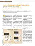
Installation
inputs. The counter is shown as a millivolt input with a direct connection to a
turbine meter sensor. J 9 and J11 are in the internal turbine meter amplifier or top
positions. The use of shielded wiring and that the shield is connected at one end
only.
When connecting to a turbine meter amplifier the manufacturer may have a
specific current requirement to power the pre-amplifier. The SCADAPack 100
does not include the necessary resistor for this application. J11 jumper would be
removed. Wire the amplifier as per the manufacturers recommendations with an
external resistor.
The counter can be used with conventional sources such as open collector
transistors and contacts. The SCADAPack 100 includes a 4700-ohm resistor
from the counter input to the DC input power source. This resistor can be used
when the SCADAPack 100 is powered from 12 or 24V. Both J9 and J11 would
be in the Dry Contact or top positions. A wiring example showing an open
collector transistor is shown in Figure 3: Digital Input/Output and Counter
Wiring.
Example jumper settings are shown below.
J9.
Turbine meter sensor uses internal
amplifier.
J11.
Turbine meter sensor uses internal
amplifier.
J9.
Open collector, dry contact or turbine
meter with external amplifier.
J11.
Open collector or dry contact. Internal
pullup resistor is used.
J11.
Open collector, dry contact or turbine
meter with external amplifier. User must
supply external resistor from input to
suitable power source.
Document (Version 2.24.1.84) 5/19/2011
17