1
B O A R D
H A R D W A R E
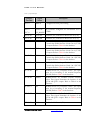
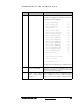
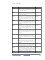
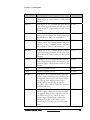
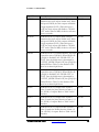
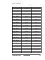
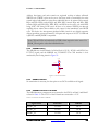
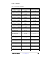
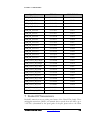
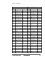
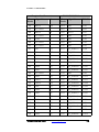
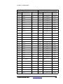
Signal Name
SMA4_RXN
FPGA Pin
Connector
U13.A6
J5
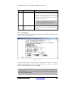
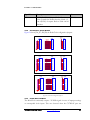
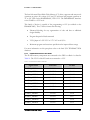
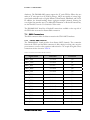
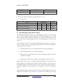
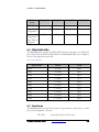
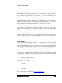
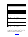
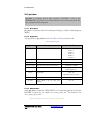
Please note the RocketIO Transceiver performance in Table 25:
Table 25 - RocketIO Performance
Item
Speed Grade
Units
-7
-6
-5
RoicketIO Tranceiver (FF)
2.5
2.5
2.0
Gb/s
PowerPC Processor Block
400
350
300
MHz
8 CPU Debug and CPU Trace
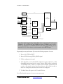
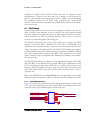
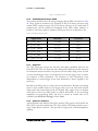
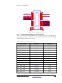
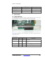
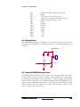
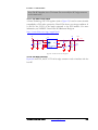
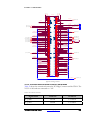
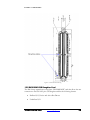
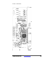
The DN6000K10SC board includes two CPU debugging interfaces, the CPU Debug
(JP1 is a vertical header) and the Combined CPU Trace and Debug, (J4 is a vertical
mictor connector). These connectors can be used in conjunction with third party tools,
or in some cases the Xilinx Parallel Cable IV, to debug software as it runs on the
processor.
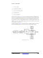
The PowerPC™ 405 CPU core includes dedicated debug resources that support a
variety of debug modes for debugging during hardware and software development.
These debug resources include:
•
Internal debug mode for use by ROM monitors and software debuggers
•
External debug mode for use by JTAG debuggers
•
Debug wait mode, which allows the servicing of interrupts while the processor
appears to be stopped
•
Real-time trace mode, which supports event triggering for real-time tracing
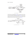
Debug modes and events are controlled using debug registers in the processor. The
debug registers are accessed either through software running on the processor or
through the JTAG port. The debug modes, events, controls, and interfaces provide a
powerful combination of debug resources for hardware and software development
tools.
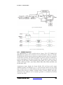
The JTAG port interface supports the attachment of external debug tools, such as the
ChipScope™ Integrated Logic Analyzer, a powerful tool providing logic analyzer
DN6000K10SC User Guide
www.dinigroup.com
117