1
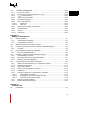
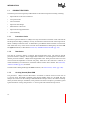
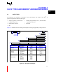
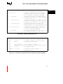
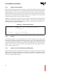
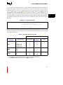
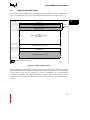
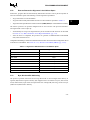
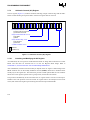
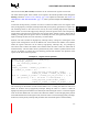
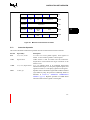
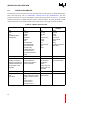
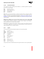
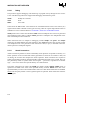
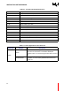
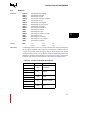
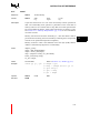
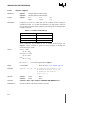
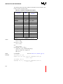
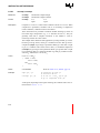
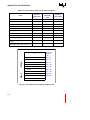
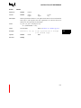
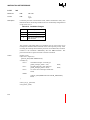
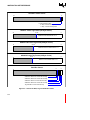
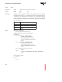
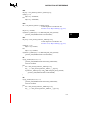
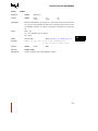
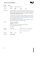
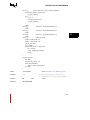
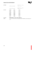
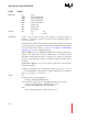
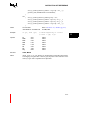
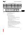
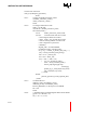
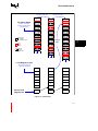
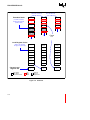
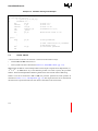
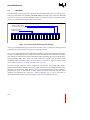
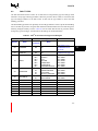
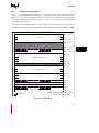
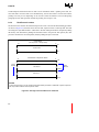
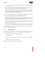
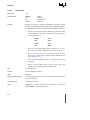
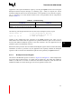
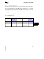
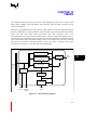
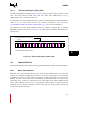
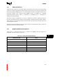
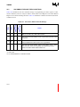
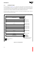
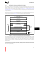
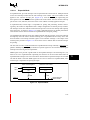
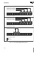
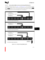
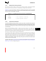
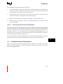
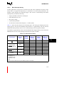
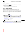
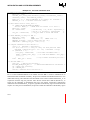
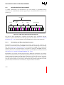
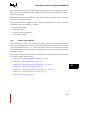
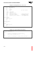
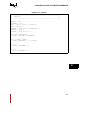
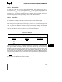
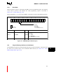
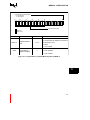
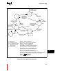
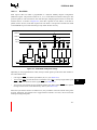
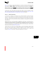
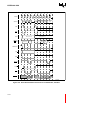
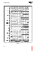
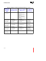
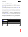
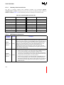
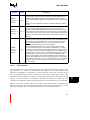
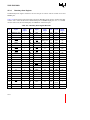
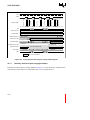
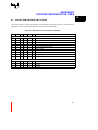
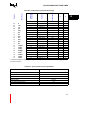
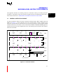
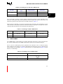
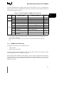
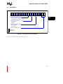
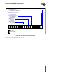
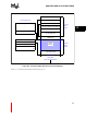
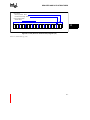
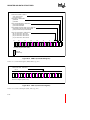
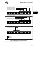
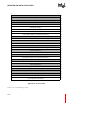
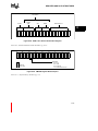
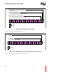
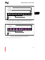
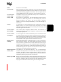
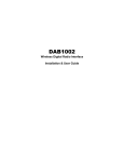
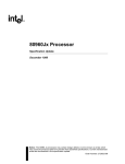
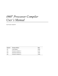
MEMORY CONFIGURATION
Logical Memory Template Enabled
0 = LMT disabled
1 = LMT enabled
28
31
24
20
16
12
M M M M M M M M M M M M M M M M M M M M
A A A A A A A A A A A A A A A A A A A A
3 3 2 2 2 2 2 2 2 2 2 2 1 1 1 1 1 1 1 1
1 0 9 8 7 6 5 4 3 2 1 0 9 8 7 6 5 4 3 2
L
M
T
E
8
4
0
Template Address Mask
Reserved,
write to zero
Mnemonic
MA31:12
Bit/Bit Field Name
Template Address
Mask
Bit Position(s)
Function
31-12
Defines upper 20 bits for the address mask
for a logical memory template. The lower 12
bits are fixed at zero.
0 = Mask
1 = Do not mask
Enables/disables logical memory template.
LMTE
Logical Memory
Template Enabled
0
0 = LMT disabled
1 = LMT enabled
Figure 13-5. Logical Memory Template Mask Registers (LMMR0-1)
13
13-9