1
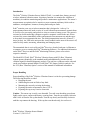
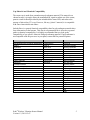
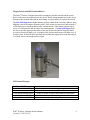
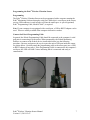
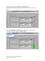
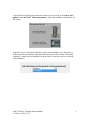
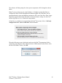
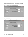
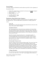
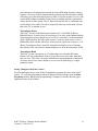
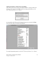
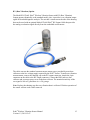
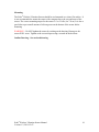
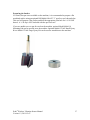
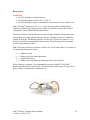
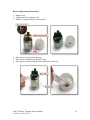
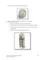
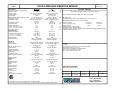
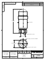
Model 670A01 Echo® Wireless Vibration Sensor Installation and Operating Manual For assistance with the operation of this product, contact PCB Piezotronics, Inc. Toll-free: 800-959-4464 24-hour SensorLine: 716-684-0001 Fax: 716-684-3823 E-mail: [email protected] Web: www.imi-sensors.com Warranty, Service, Repair, and Return Policies and Instructions The information contained in this document supersedes all similar information that may be found elsewhere in this manual. Total Customer Satisfaction – PCB Piezotronics guarantees Total Customer Satisfaction. If, at any time, for any reason, you are not completely satisfied with any PCB product, PCB will repair, replace, or exchange it at no charge. You may also choose to have your purchase price refunded in lieu of the repair, replacement, or exchange of the product. Service – Due to the sophisticated nature of the sensors and associated instrumentation provided by PCB Piezotronics, user servicing or repair is not recommended and, if attempted, may void the factory warranty. Routine maintenance, such as the cleaning of electrical connectors, housings, and mounting surfaces with solutions and techniques that will not harm the physical material of construction, is acceptable. Caution should be observed to insure that liquids are not permitted to migrate into devices that are not hermetically sealed. Such devices should only be wiped with a dampened cloth and never submerged or have liquids poured upon them. Repair – In the event that equipment becomes damaged or ceases to operate, arrangements should be made to return the equipment to PCB Piezotronics for repair. User servicing or repair is not recommended and, if attempted, may void the factory warranty. Calibration – Routine calibration of sensors and associated instrumentation is recommended as this helps build confidence in measurement accuracy and acquired data. Equipment calibration cycles are typically established by the users own quality regimen. When in doubt about a calibration cycle, a good “rule of thumb” is to recalibrate on an annual basis. It is also good practice to recalibrate after exposure to any severe temperature extreme, shock, load, or other environmental influence, or prior to any critical test. PCB Piezotronics maintains an ISO9001 certified metrology laboratory and offers calibration services, which are accredited by A2LA to ISO/IEC 17025, with full traceablility to N.I.S.T. In addition to the normally supplied calibration, special testing is also available, such as: sensitivity at elevated or cryogenic temperatures, phase response, extended high or low frequency response, extended range, leak testing, hydrostatic pressure testing, and others. For information on standard recalibration services or special testing, contact your local PCB Piezotronics distributor, sales representative, or factory customer service representative. Returning Equipment – Following these procedures will insure that your returned materials are handled in the most expedient manner. Before returning any equipment to PCB Piezotronics, contact your local distributor, sales representative, or factory customer service representative to obtain a Return Materials Authorization (RMA) Number. This RMA number should be clearly marked on the outside of all package(s) and on the packing list(s) accompanying the shipment. A detailed account of the nature of the problem(s) being experienced with the equipment should also be included inside the package(s) containing any returned materials. PCB for a complete statement of our warranty. Expendable items, such as batteries and mounting hardware, are not covered by warranty. Mechanical damage to equipment due to improper use is not covered by warranty. Electronic circuitry failure caused by the introduction of unregulated or improper excitation power or electrostatic discharge is not covered by warranty. A Purchase Order, included with the returned materials, will expedite the turn-around of serviced equipment. It is recommended to include authorization on the Purchase Order for PCB to proceed with any repairs, as long as they do not exceed 50% of the replacement cost of the returned item(s). PCB will provide a price quotation or replacement recommendation for any item whose repair costs would exceed 50% of replacement cost, or any item that is not economically feasible to repair. For routine calibration services, the Purchase Order should include authorization to proceed and return at current pricing, which can be obtained from a factory customer service representative. Contact Information – International customers should direct all inquiries to their local distributor or sales office. A complete list of distributors and offices can be found at www.pcb.com. Customers within the United States may contact their local sales representative or a factory customer service representative. A complete list of sales representatives can be found at www.pcb.com. Toll-free telephone numbers for a factory customer service representative, in the division responsible for this product, can be found on the title page at the front of this manual. Our ship to address and general contact numbers are: Warranty – All equipment and repair services provided by PCB Piezotronics, Inc. are covered by a limited warranty against defective material and workmanship for a period of one year from date of original purchase. Contact DOCUMENT NUMBER: 21354 DOCUMENT REVISION: B ECN: 17900 PCB Piezotronics, Inc. 3425 Walden Ave. Depew, NY 14043 USA Toll-free: (800) 828-8840 24-hour SensorLineSM: (716) 684-0001 Website: www.pcb.com E-mail: [email protected] Echo® Wireless Vibration Sensor User’s Manual Models: 670A01, RV670A01 and CS670A01 41967 Rev C ECO#: 43669 Table of Contents FCC NOTICE ..................................................................................................................... 3 INDUSTRY CANADA (IC) NOTICE ............................................................................... 3 HAZARDOUS AREA USE ............................................................................................... 3 Introduction ......................................................................................................................... 4 Proper Handling .................................................................................................................. 4 Cap Material and Chemical Compatibility ......................................................................... 5 Magnet Switch and LED Status Indicator .......................................................................... 6 LED Status Messages ..................................................................................................... 6 Programming the Echo® Wireless Vibration Sensor .......................................................... 7 Programming................................................................................................................... 7 Connect the Echo® Programming Cable ........................................................................ 7 Connect to the Sensor with the Echo® Monitoring Software ........................................ 8 Click on Configuration on the menu bar. You should see a screen similar to the following, and then click on Echo® EchoPlus® Sensors. .............................................. 8 Factory Defaults ............................................................................................................ 12 Explanation of Echo® Wireless Sensor Parameters ..................................................... 12 Parameters can be changed by using the up and down arrows or by typing the values in the appropriate box. Click on the Set button by the parameter to actually program the sensor. ........................................................................................................................... 12 Sensor ID ...................................................................................................................... 12 Transmission Interval.................................................................................................... 12 RVL (Residual Vibration Level) .................................................................................. 12 CF Report Threshold..................................................................................................... 12 Transmission Power ...................................................................................................... 13 Transmission Band........................................................................................................ 13 Saving Changes to the Echo® Sensor............................................................................ 13 Updating the Database to Match Sensor Programming ................................................ 14 RV (Raw Vibration) Option.............................................................................................. 15 Mounting ........................................................................................................................... 16 Outline Drawing (See Attachment) .................................................................................. Preparing the Surface .................................................................................................... 17 Battery Pack ...................................................................................................................... 18 Battery Replacement Instructions ..................................................................................... 19 Echo® Wireless Vibration Sensor Manual Version 1.2, 2011-12-07 2 FCC NOTICE FCC ID: ZOC-IMI670A01 This device complies with part 15 of the FCC Rules. Operation is subject to the following two conditions: (1) This device may not cause harmful interference, and (2) this device must accept any interference received, including interference that may cause undesired operation. Changes or modifications not expressly approved by the party responsible for compliance could void the user's authority to operate the equipment. This equipment has been tested and found to comply with the limits for a Class A digital device, pursuant to part 15 of the FCC Rules. These limits are designed to provide reasonable protection against harmful interference when the equipment is operated in a commercial environment. This equipment generates, uses, and can radiate radio frequency energy and, if not installed and used in accordance with the instruction manual, may cause harmful interference to radio communications. Operation of this equipment in a residential area is likely to cause harmful interference in which case the user will be required to correct the interference at his own expense. INDUSTRY CANADA (IC) NOTICE IC: 9732A-IMI670A01 Operation is subject to the following two conditions: (1) this device may not cause interference, and (2) this device must accept any interference, including interference that may cause undesired operation of the device. HAZARDOUS AREA USE Warning- Explosion Hazard- Do Not Disconnect or connect while circuit is live unless area is known to be non-hazardous. Batteries must not be changed unless area is known to be Non-Hazardous. Do not open when an explosive atmosphere may be present. Substitution of components may impair suitability for Class I, Div 2. Advertissment- Risque D’explosion – Ne pas debrancher ou brancher tant que le circuitest sous tension. A moins qu’il ne s’agisse d’un emplacement non dangereux. Les piles ne doivent pas etre remplacees a moins qu’il ne s’agisse d’un emplacement non dangereux. N'ouvrez pas lorsqu'une atmosphère explosive peut être présente. Remplacement de composants peut nuire à la conformité de Classe I Div 2. Echo® Wireless Vibration Sensor Manual Version 1.2, 2011-12-07 3 Introduction The Echo® Wireless Vibration Sensor, Model 670A01, is a stand alone, battery powered, wireless, industrial vibration sensor. Its primary function is to monitor the vibration of machinery in condition monitoring and predictive maintenance applications. The sensor’s measurements are optimized to be sensitive to most common machinery faults such as: unbalance, misalignment, looseness, bearing faults and gear faults. Echo® contains a one-way wireless transmitter that is designed to “wake up” at preprogrammed intervals, make a series of overall vibration measurements, transmit them to a receiver for processing, and go back to sleep to conserve battery power. The sensor is activated or deactivated using a magnet to operate a magnetic switch in the unit. When activated, the sensor immediately makes and transmits a measurement set and then goes to sleep until its next transmission time. The default transmission interval is 8-hours (3 times per day). An LED in the unit provides visual feedback on the state of the sensor: off, on but in sleep mode, measuring, transmitting and changing states. The transmitted data is received by an Echo® Receiver, decoded, and sent via Ethernet to a computer or server running the Echo® Monitoring Software. For additional information on the Echo® Receiver and the Echo® Monitoring Software, please refer to their respective manuals. The Model RV670A01 Echo® Wireless Vibration Sensor with RV (Raw Vibration) Output operates identically to the standard model and additionally, provides the raw vibration signal for detailed diagnostic analysis. The unit has a connector on the side and can be used with an optional Model 070A86 Echo® RV Output Cable for analysis. See the “RV (Raw Vibration) Option” section of this manual for additional information. Proper Handling Proper handling of the Echo® Wireless Vibration Sensor is critical to preventing damage. The following should be avoided: Dropping the unit. Submersing the units in fluids of any kind. Mounting the sensor by twisting the housing. Exposing the unit to temperatures above 158° F. Exposing the cap to any reactive chemicals. Caution - The sensor cap is easily cross threaded. To avoid cross threading, press down lightly on the cap to compress the battery securing foam. Turn the cap counter-clockwise until a click is heard to line up the threads. Turn the cap slowly and carefully clockwise until the cap contacts the housing. If the cap does not thread easily, do not force it. Echo® Wireless Vibration Sensor Manual Version 1.2, 2011-12-07 4 Cap Material and Chemical Compatibility The sensor cap is made from a translucent polycarbonate material. This material was chosen because it is tough, allows the transmitted RF signal to radiate out of the sensor, permits visual feedback provided by the imbedded blue status LED, and reduces the passage of ultraviolet (UV) rays. However, like any “plastic” material, it is compatible with some chemicals but not others. Included here is a general chemical compatibility chart for polycarbonate material taken from information on the Internet. This data is not guaranteed but is offered as a general guide to chemical compatibility. It is highly recommended that you look up the compatibility of you specific chemical with polycarbonate material. If polycarbonate is not compatible with the processes in your plant, contact IMI for potential options. Will Damage Polycarbonate Alkali bleaches such as sodium hypochlorite Acetone Acrylonitrile Require Caution Cyclohexanone Diesel oil Formic acid Considered Safe Acetic acid Ammonium chloride Antimony trichloride Ammonia Amyl acetate Benzene Bromine Butyl acetate Sodium hydroxide Chloroform Dimethylformamide Concentrated hydrochloric acid Concentrated hydrofluoric acid Iodine Methanol Methyl ethyl ketone Styrene Tetrachloroethylene Toluene Concentrated sulfuric acid Xylene Cyanoacrylate monomers Gasoline Glycerine Heating oil Jet fuel Concentrated perchloric acid Sulfur dioxide Turpentine Borax in H2O Butane Calcium chloride Calcium hypochlorite Carbon dioxide Carbon monoxide Citric acid 10% Copper(II) sulfate Ethyl alcohol, i.e. ethanol 95% Ethylene glycol Formaldehyde 10% Hydrochloric acid 20% Hydrofluoric acid 5% Isopropyl alcohol Mercury Methane Oxygen Ozone Sulfur Urea Water Echo® Wireless Vibration Sensor Manual Version 1.2, 2011-12-07 5 Magnet Switch and LED Status Indicator The Echo® Wireless Vibration Sensor has a magnetic switch located inside the sensor that is used to activate and deactivate the sensor. Hold a strong magnet next to the sensor housing at the location indicated on the housing, see figure below, to operate the switch. The blue LED light should begin blinking quickly within about 4 seconds. When it starts blinking, remove the magnet from the sensor. If the sensor was previously deactivated it will become active and immediately take a measurement. If the sensor was previously active, it will deactivate and no longer take measurements. The blue LED light allows the user to quickly determine the status of the unit by the time interval between blinks. An active sensor will blink every 4 seconds while a deactivated sensor will blink every 8 seconds. Note: If the LED does not blink after holding the magnet next to the housing for 5 seconds, remove the magnet and try again. LED Status Messages Blue LED Message Fast continuous blinking 4 second intermittent blink 8 second intermittent blink Dim illuminated LED Bright illuminated LED Sensor Status Magnet switch is currently being activated. Sensor is turned on and waiting for the next transmission. Sensor is turned off and will not make measurements. Sensor is currently measuring vibration levels. Sensor is currently transmitting information to receiver. Echo® Wireless Vibration Sensor Manual Version 1.2, 2011-12-07 6 Programming the Echo® Wireless Vibration Sensor Programming The Echo® Wireless Vibration Sensor can be programmed with a computer running the Echo® Monitoring Software through a serial port. While this is a serial port in the sensor, a micro USB connector is used in order to fit into the small space. A special (optional) Echo® Programming Cable, Model 070A87, is required. Note: If your computer is not equipped with a serial port, a USB to RS232 adaptor can be used. These are readily available from computer electronics vendors. Connect the Echo® Programming Cable In general, the Echo® Programming Cable should be connected to the computer’s serial port prior to connecting it to the sensor. When prompted by the Echo® Monitoring Software to connect to the Echo® device (instructions below) use the following procedure. Unscrew and remove the cap to expose the micro USB port inside the sensor, see photos below. Carefully attach the programming cable to the sensor port (use a USB to RS232 adaptor if necessary). If the Programming Cable is connected to the computer’s serial port, the LED will blink 5 times indicating that it is connected and ready to communicate. Echo® Wireless Vibration Sensor Manual Version 1.2, 2011-12-07 7 Connect to the Sensor with the Echo® Monitoring Software Launch the Echo® Monitoring Software. You should see a screen similar to the one below. Click on Configuration on the menu bar. You should see a screen similar to the following, and then click on Echo® EchoPlus® Sensors. Echo® Wireless Vibration Sensor Manual Version 1.2, 2011-12-07 8 You should see the following selections on the next screen. Click on ‘I want to add | update | view and Echo® Sensors parameters’, then click on Next > at the bottom of the screen. Select the receiver where data from this specific sensor should be sent. This also, by default, specifies the database where data from this sensor will be stored. The default setting for a single receiver installation is shown below. After the receiver is selected, click on Next >. Echo® Wireless Vibration Sensor Manual Version 1.2, 2011-12-07 9 The software will then prompt for what system components will be changed as shown below. Note: If you are setting up your actual database, it is highly recommended that you configure the Echo® Sensor and update the database together. By doing this, you are guaranteed that the sensor and database parameters will be set to the same values. Some important program information and alarms are based on theses settings. See the Echo® Monitoring Software User’s Manual for setup details. At this time, we will focus on programming the Echo® Sensor only. Select ‘I will only configure the Echo® device at this time’ and click Next >. When the following screen is displayed, make sure the Echo® Programming Cable is connected to the computer, then; connect the micro USB connector to the sensor. After the blue LED blinks 5 times, click OK. Echo® Wireless Vibration Sensor Manual Version 1.2, 2011-12-07 10 The following connection window will appear. Select the appropriate COM port and click on Link to Echo®. Note: The Access Level is factory set and is not user selectable. The green bar should illuminate indicating the connection has been made. The fields to the right of the window will populate with the current programmed parameters. Echo® Wireless Vibration Sensor Manual Version 1.2, 2011-12-07 11 Factory Defaults The factory defaults are defined below unless otherwise specified. See the explanation of the parameters below. Sensor ID is a unique factory set number for each sensor and cannot be changed. Transmission Interval = 8 hours RVL = 0 (off) CF Repot Threshold = 0.02 Transmission Power = High Transmission Band = 1 Explanation of Echo® Wireless Sensor Parameters Parameters can be changed by using the up and down arrows or by typing the values in the appropriate box. Click on the Set button by the parameter to actually program the sensor. Sensor ID The Sensor ID is a unique ID programmed into and etched onto each sensor at the factory. This number cannot be changed. Transmission Interval The Transmission Interval is the time between transmissions of measured data. The factory default is 8 hours. That means the sensor will “wake up” and make a measurement every 8 hours (3 times per day). At the default 8 hour transmission interval, the primary lithium-thionyl chloride (Li-SOCl2) batteries are expected to last in excess of 5 years. Note: Decreasing the transmission interval (i.e., increasing the number of measurements per day) will not only reduce battery life but will also use more receiver bandwidth. Thus, fewer sensors can be used with a receiver. See the Echo® Receiver User’s Manual for guidelines regarding the number of sensors that can be used per receiver. RVL (Residual Vibration Level) The RVL is an rms velocity level in ips (inches/second). If it is set to 0 (zero), the feature is off and the sensor will wake up at the programmed interval, make measurements, and transmit them. If a value is set, the sensor will wale up at the programmed interval and start a measurement. If the rms velocity is ≥ the RVL, the measurement and transmission will proceed as normal. If the rms velocity is < the RVL, the machine is assumed to be off and the measurement is terminated. This both conserves battery power and minimizes the transmission of “bad data”. CF Report Threshold CF (crest factor) is the ratio of true peak acceleration divided by rms acceleration. For a sine wave, this value is 1.414. Echo® sensors high pass filter both the true Echo® Wireless Vibration Sensor Manual Version 1.2, 2011-12-07 12 peak and rms acceleration measurements for better HFE (high frequency energy) response. This type of filtered measurement generally provides an earlier warning of bearing, gear, and other high frequency faults. It can also result in very low rms acceleration readings (sometimes in the noise) for healthy machines, particularly if they operate at slow speeds. The CF Report Threshold value is a minimum rms acceleration level at which CF will be computed. If the rms acceleration is below this value, CF is returned as zero. Transmission Power The Echo® Wireless Vibration Sensor transmits at 0.75 mW ERP (Effective Radiated Power). In some cases, the sensor may be so close to the antenna and the signal strength so strong, that the receiver will see “reflections” of the transmitted signal. While this does not affect data accuracy, it can use unnecessary receiver bandwidth to deal with the reflections. If the received signal from a sensor is > 65 dB, the Transmission Power should be changed from High to Low to eliminate this problem. This will cause the transmitted power to be reduced by about 45 dB. Transmission Band The Echo® System can operate on 12 independent user selectable RF bands. Sensors will only communicate with receivers that are set to the same band that they are set to. This allows for large installations requiring hundreds or thousands of sensors and in cases where distances are too far to be picked up by a single antenna location. Saving Changes to the Echo® Sensor Click the Set button next to each field to be updated to program the value in the Echo® Sensor. To verify the programming when all changes have been made, click the Read Parameters button. When sensor programming is completed, click the X in the upper right hand corner of the window. Echo® Wireless Vibration Sensor Manual Version 1.2, 2011-12-07 13 Updating the Database to Match Sensor Programming If the sensor has not been previously entered into the database, a message similar to the following will be displayed. Click OK. For details on setting up the database, see the Echo® Monitoring Software User’s Manual. A screen similar to the following will be displayed. Ignore the screen and click Finish. This will be used when you set up the actual database. For complete programming options, see the Echo® Monitoring Software User’s Manual. Echo® Wireless Vibration Sensor Manual Version 1.2, 2011-12-07 14 RV (Raw Vibration) Option The Model RV670A01 Echo® Wireless Vibration Sensor with RV (Raw Vibration) Output operates identically to the standard model, plus, it provides a raw vibration output signal for detailed diagnostic analysis. The unit has a connector on the side of the housing that can be used with an optional Model 070A86 Echo® RV Output Cable that provides the analog acceleration signal directly from the embedded accelerometer. The cable converts the standard constant current sensor power provided by most data collectors to the low voltage supply required by the Echo® Sensor. To make raw vibration measurements, remove the shorting cap on the RV output connector. Attach the 4-pin connector on the cable to the RV output connector. Connect the BNC end to a data collector and set sensor power to on in the data collector. The nominal sensitivity of the raw signal is 100 mV/g and there is a ± 20 g range. Note: Replace the shorting cap after raw vibration data is collected. Wireless operation of the sensor will not work with it removed. Echo® Wireless Vibration Sensor Manual Version 1.2, 2011-12-07 15 Mounting The Echo® Wireless Vibration Sensor should be stud mounted on a clean, flat surface. It is not recommended to mount the sensor with a magnet due to the size and mass of the sensor. The correct mounting torque for the sensor is 3 to 5 ft-lb (4 to 7 N-m). It is also a good idea to put a small amount of silicon grease on the bottom of the sensor before mounting. WARNING – Do NOT tighten the sensor by twisting on the housing. Damage to the sensor WILL occur. Tighten to the correct torque using a wrench on the hex base. Outline Drawing – See enclosed drawing Echo® Wireless Vibration Sensor Manual Version 1.2, 2011-12-07 16 Preparing the Surface If a clean, flat spot is not available on the machine, it is recommended to prepare a flat machined surface using an optional IMI Model 080A127 1” spot face tool, shown below. This tool will prepare a flat surface and drill the appropriate pilot hole for a ¼-28 UNF thread. A ¼-28 tap is NOT included with the spot face tool. If you are unable to use a spot face tool on the machine, optional Model 080A118 Mounting Pad can be epoxied on to the machine. Optional Model 075A05 Small Epoxy Kit or Model 075A06 Large Epoxy Kit can be used to attach them to the machine. Echo® Wireless Vibration Sensor Manual Version 1.2, 2011-12-07 17 Battery Pack WARNING Do NOT attempt to recharge batteries Do NOT heat batteries above 212 °F (100 °C) Do NOT attempt to replace with standard AA size batteries, they will not work. Note: The Echo® Sensor uses two 3.6 V, A-size (not AA) primary lithium-thionyl chloride (Li-SOCl2) high energy density, bobbin cell batteries in series that are NOT rechargeable. Please contact IMI for replacements. The Echo® Wireless Vibration Sensor accurately measures battery voltage during each measurement cycle and transmits the battery status. The battery status is available for display in the Echo® Monitoring Software. See the Echo® Monitoring Software User’s Manual for details on monitoring the battery status. The following are recommended actions based on battery status. Note: The battery decline is not linear; it will be at a 3 level longer than a 2 level and at a 0 level the shortest amount of time. 3 = Battery is good 2 = Battery good but order replacement 1 = Replace the battery 0 = Battery bad, stop taking measurements with it until replaced When a battery is required, it is recommended you order a Model 073A20 Echo® Replacement Battery Kit, shown below. The kit includes a battery pack, 0-ring, silicon grease, battery securing foam, and instructions. Echo® Wireless Vibration Sensor Manual Version 1.2, 2011-12-07 18 Battery Replacement Instructions 1. Remove Cap 2. Unplug and remove battery pack 3. Remove O-ring and battery securing foam 4. Place the new O-ring on the housing 5. Place grease completely around the O-ring 6. Place grease on and around the barb on the inside of the cap Echo® Wireless Vibration Sensor Manual Version 1.2, 2011-12-07 19 7. Place the battery securing foam on the barb in the cap 8. Plug in the new battery cap and place the battery pack in the housing 9. Screw cap onto the housing a. Make sure that the foam is centered on top of the batteries. b. Compress foam and hold so the threads of the cap and housing are touching. c. Turn the cap counter clock wise unit you hear two clicks (This will prevent cross threading) d. Thread the cap on to the housing until it bottoms out. Echo® Wireless Vibration Sensor Manual Version 1.2, 2011-12-07 20 Model Number 670A01 Performance ENGLISH RMS Velocity Frequency Range(± 3 dB) 4 to 2300 Hz Velocity HP Filter 2 Hz, 1-pole RC Velocity LP Filter 2400 Hz,3-pole Chebyshev Velocity Resolution 0.001 ips rms Velocity Range 4 ips rms RMS Acceleration Frequency Range(± 3 dB) 2200 to 15,000 Hz Acceleration HP Filter 2000 Hz,4-pole Chebyshev 15k Hz, 3-pole Chebyshev + 1Acceleration LP Filter pole RC Acceleration Resolution 0.007 g pk Acceleration Range 20 g pk Transverse Sensitivity ≤7% Velocity Linearity(0-1 ips rms) <1 % Velocity Linearity(0-4 ips rms) <8.5 % Acceleration Linearity <1 % SI 4 to 2300 Hz 2 Hz, 1-pole RC 2400 Hz,3-pole Chebyshev 0.025 mm/s rms 101.6 mm/s rms 2200 to 15,000 Hz 2000 Hz,4-pole Chebyshev 15k Hz, 3-pole Chebyshev + 1pole RC 0.069 m/s² pk 196.2 m/s² pk ≤7% <1 % <8.5 % <1 % [2] 1000 g pk -4 to +158 °F -40 to +250 °F -76 to +185 °F IP66 250 ft to>1 mile radius, installation dependent 9810 m/s² pk -20 to +70 °C -40 to +121 °C -60 to +85 °C IP66 250 ft to>1 mile radius, installation dependent Analog Integration, FFT Sum 3.7 Sec time sample @ 61.4 kHz sample rate 16 900 MHz ISM Band 12 0.75 mW 20 bps 16 bit/>90db >5 years @ 3-measurements per day >108 Ohm Analog Integration, FFT Sum 3.7 Sec time sample @ 61.4 kHz sample rate 16 900 MHz ISM Band 12 0.75 mW 20 bps 16 bit/>90db >5 years @ 3-measurements per day >108 Ohm 7.2V Lithium Battery Pack 1.375 in x 4.40 in Ceramic 1 lb Shear Stainless Steel 1.66 in 1/4" - 28 3 to 5 ft-lb O-Ring Magnet Switch 7.2V Lithium Battery Pack 34.93 mm x 111.8 mm Ceramic 454 g Shear Stainless Steel 42.0 mm 1/4" - 28 4 to 7 Nm O-Ring Magnet Switch ECN #: 42742 OPTIONAL VERSIONS Optional versions have identical specifications and accessories as listed for the standard model except where noted below. More than one option may be used. CS - Canadian Standards Association Approved Intrinsically Safe [2] [6] M - Metric Mount Supplied Accessory : Model M081A61 Mounting Stud 1/4-28 to M6 X 1 (1) RV - Buffered Analog Signal Output - 100 mV/g (±20%) [3] [3] [4] [4] [4] Environmental Overload Limit(shock) Temperature Range(electronics) Temperature Range(base) Temperature Range(battery) Enclosure Rating Transmission Range Revision: C ECHO® WIRELESS VIBRATION SENSOR Electrical Connector 1/4-28 4-Pin 1/4-28 4-Pin Frequency Range(± 3 dB) 1 to 15,000 Hz 1 to 15,000 Hz Settling Time(1%) ≤ 4 sec ≤ 4 sec Optional Accessory : Model 070A86 Supplied Accessory : Model 070A88 (1) Supplied Accessory : Model ICS-2 NIST-traceable single-axis single-point amplitude response calibration at 6000 cpm (100 Hz) (1) [1] Electrical RMS Velocity RMS Acceleration Filtered Crest Factor(max) Frequency Band Number of RF Bands Maximum Power(ERP) RF Data Rate ADC/dynamic range Battery Life(room temperature) Electrical Isolation NOTES: [1] [2] [3] [4] [5] [6] Typical. Upper frequency tolerance is ± 10% of the specified value. Conversion Factor 1g = 9.81 m/s². Zero-based, least-squares, straight line method. 1/4-28 has no equivalent in S.I. units. CL 1, Div 2, Groups A, B, C, D, T5 Physical Power Size (Hex x Height) Sensing Element Weight Sensing Geometry Housing Material Housing Diameter Mounting Mounting Torque Sealing Sensor Activation/Deactivation All specifications are at room temperature unless otherwise specified. In the interest of constant product improvement, we reserve the right to change specifications without notice. SUPPLIED ACCESSORIES: Model 081A40 Mounting Stud (1) [5] Entered: AP Engineer: gs Sales: SA Approved: BAM Spec Number: Date: 4/8/2014 Date: 4/8/2014 Date: 4/8/2014 Date: 4/8/2014 42657 3425 Walden Avenue, Depew, NY 14043 Phone: 800-959-4464 Fax: 716-684-3823 E-Mail: [email protected] 2 1 REVISIONS 41966 PCB Piezotronics Inc. claims proprietary rights in the information disclosed hereon. Neither it nor any reproduction thereof will be disclosed to others without the written consent of PCB Piezotronics Inc. REV DESCRIPTION DIN A UPDATED CAP 43669 B B 4.4 [112] Ø1.66 [42.0] 1/4-28 UNF-2B x.20 [5.3] Ø.87 [22.1] n1.50 [38.1] ACROSS CORNERS 1.375 [34.9] HEX A A 1/4-28 UNF - 2B x .20 [5.3] UNLESS OTHERWISE SPECIFIED TOLERANCES ARE: DIMENSIONS IN INCHES DECIMALS XX ±.03 XXX ±.010 DIMENSIONS IN MILLIMETERS [ IN BRACKETS ] DECIMALS X ± 0.8 XX ± 0.25 ANGLES ` 2 DEGREES ANGLES ` 2 DEGREES FILLETS AND RADII .003 - .005 FILLETS AND RADII 0.07 - 0.13 2 DRAWN BB CHECKED 01/23/15 ECB 01/23/15 ENGINEER BAM 01/23/15 3425 WALDEN AVE. DEPEW, NY 14043 (716) 684-0001 E-MAIL: [email protected] TITLE OUTLINE DRAWING 670A01 WIRELESS DWG. NO. CODE IDENT. NO. 52681 SCALE: FULL 1 41966 SHEET 1 OF 1