1
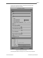
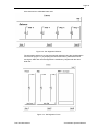
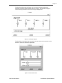
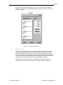
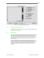
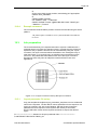
Page 239
The name of the mark definition for the global alignment marks.
[$ Global_Mark_Locate
:== AUTO]
This is optional and defaults to MAN. Defines mark locate procedure during
global alignment: MAN requires a manual stage alignment using the joystick
before each mark locate, AUTO just uses the automatic mark locate at the
expected global mark positions.
$ REFERENCEOFFSET
:== -20 -19
The distance from the centre of the layout to a reference feature which is usually
well away from the dies to be exposed to avoid accidental exposure during the
initial search on the substrate. This is useful for the initial coarse global
alignment before the final global alignment is carried out. If 999 is used then no
reference feature search will be carried out.
$ Global_cell_1
$ Global_cell_2
$ Global_cell_3
$ Global_cell_4
:== 2 2 1
:== 4 2 1
:== 2 4 1
:== 4 4 1
! 999 for only 2 mark global
! 999 for only 3 mark global alignment
These symbols define the alignment marks used for the global alignment. The
first 2 symbols must be defined, as a minimum of 2 marks are required for global
alignment. The 3rd and 4th marks are optional. If 999 is entered for Global_cell_3
then only 2 marks are used for global alignment. If 999 is entered for
Global_cell_4 then only 3 marks are used for global alignment. The first two
numbers of each symbol are the X Y indices of the global cells. The third number
is the alignment mark number within a cell.
[$ Global_cell_1_POS
[$ Global_cell_2_POS
[$ Global_cell_3_POS
[$ Global_cell_4_POS
:== 55.746 32.495
:== 999
:== 999
:== 999
! 999 for no stored global position]
! 999 for no stored global position]
! 999 for no stored global position]
! 999 for no stored global position]
These symbols are optional and the defaults are the expected positions
calculated from the layout parameters. They may be used to define more
accurate X Y positions for the global marks than the expected positions
calculated from the layout parameters. Such positions can come from substrate
measurements before exposure and allow more easily a batch of substrates to
be exposed reliably with the same jobfile, especially if automatic global alignment
is used. The search for the global marks will be carried out at these positions
instead of the normal expected positions. It is not necessary to define these
positions and they may all be set to 999.
$------------------------------------------------------------------------------------------------------$! Die-by-die alignment parameters
$------------------------------------------------------------------------------------------------------$ DirectWriteStrategy
:== DW2
Defines the method used:
DW1 means that no die-by-die alignment is carried out but just the previous
global alignment is used.
DW2 means die-by-die alignment is carried out and all four marks of each die
are located before exposing each die. When the machine only finds 0,1 or 2
alignment marks a warning message is generated and the die is not processed.
DW3 means die-by-die alignment is carried out by measuring only those marks
which have not already been measured. If neighbouring dies use the same
alignment marks then the mark is only located once the first time it is
encountered and then stored in memory. When the machine only finds 0,1 or 2
alignment marks a warning message is generated and the die is not processed.
Part Number:878275
Vectorbeam Operator Manual