1
4.0 QUICK INSTALLATION GUIDE
These simple instructions will get your Chief starter set up & running
quickly. If you are adding a DCS100 or DT100 to your current Digitrax
system please refer to section 5.0. You can investigate the specifics later but,
for now let's get your trains running. A full description of all controls &
technical reference information are included later in this manual.
Before you begin your installation be aware that the addition of DCC to your
layout will not correct existing wiring problems. Usually, if you can run an
analog engine smoothly on your railroad, you won't have a problem hooking
up DCC. If you do have concerns about your existing wiring, start by running
the Chief on a separate loop of temporary track.
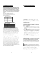
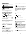
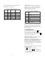
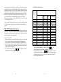
F) The DCS100 will "beep" & the "Power ON" indicator
will light up
GREEN. Also, the
indicator will glow steady RED, showing that the
unit is in "RUN" mode & that the LocoNet network is OK. If the unit has
indicator will be GREEN with a single brief
been configured the
"wink" off about every 4 seconds. The red “OVER TEMP” light will also
be lit. The full meanings of these indicators are covered in section 9.2.
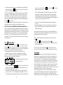
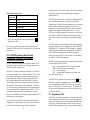
G) The "Track Status" indicator should be off at this point. This is the
normal system default after input power is applied to the DCS100.
Now that the DCS100 is ready to go, we can connect a throttle to it & start
running the layout.
4.1 Making Track & Booster Connections
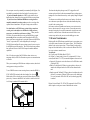
See the “Chief Set Quick Start Hook Up Diagram,” Diagram 1.
A) Start with the DCS100 & your conventional power pack or other suitable
transformer. See section 6.0 for information on how to choose an
appropriate power supply.
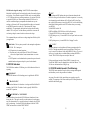
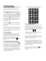
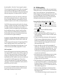
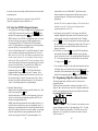
B) Set the
SCALE switch on the DCS100 to the scale you are running N,
HO, O\G(also used for S). To get the best low speed performance, we
recommend using the DCS100 in the "N" scale setting (even if you are
running HO). When running analog locomotives (without decoders) we
strongly suggest that you use the "N" scale setting to give quieter
operation & generate less heat build up in the analog engines.
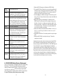
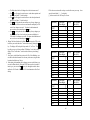
C) Set the
MODE switch on the DCS100 to the "RUN" position.
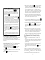
D) The GREEN wire on the back of the DCS100 provides electrical safety
features and an RF ground reference for minimum radiated noise. It should
be the ONLY point of any installation that is connected to the AC safety
ground pin provided on most 3 pin 110V AC power sockets. If the power
outlet is a 2 pin ungrounded unit, this ground terminal can be connected with
a GREEN 14 AWG multi-stranded conductor to a cold metallic water pipe
ground, as defined in the National Electrical Code. This is a safety
precaution that should not be ignored.
E) Connect the two POWER IN terminals to the output of your transformer
or power supply source. Turn on your power supply to send power to the
DCS100.
9
10