1
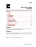
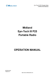
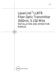
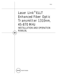
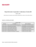
ADCP-90-270 x Issue 1 x March 2000
NGF Fiber Optic Terminal Storage Bay (FOTSB)
User Manual)
13987-A
Fiber Optic Terminal Storage Bay
Content
1
GENERAL.......................................................................... 2
2
PRODUCT DESCRIPTION ............................................................... 2
3
4
1070073 Rev A
Page
2.1
Functional Description ........................................................... 2
2.2
Physical Description ............................................................ 3
INSTALLATION ...................................................................... 3
3.1
Securing the Storage Bay to a Frame ................................................. 4
3.2
Securing the Storage Bay to an End Guard .............................................. 6
3.3
Concrete Floor Mounting.......................................................... 7
3.4
Raised Floor Mounting ........................................................... 9
3.5
Removing the Bend Radius Limiter...................................................12
3.6
Cabling .....................................................................15
CUSTOMER INFORMATION AND ASSISTANCE .................................................17
Page 1
© 2000, ADC Telecommunications, Inc.
ADCP-90-270 x Issue 1 x March 2000
Revision History
ISSUE
DATE
Issue 1
03/2000
REASON FOR CHANGE
Original
Trademark Information
ADC and ADC Telecommunications are registered trademarks of ADC Telecommunications, Inc.
Next Generation Frame is a registered trademark of ADC Telecommunications, Inc.
Admonishments
Important safety admonishments are used throughout this manual to warn of possible hazards
to persons or equipment. An admonishment identifies a possible hazard and then explains
what may happen if the hazard is not avoided. The admonishments — in the form of Dangers,
Warnings, and Cautions — must be followed at all times. These warnings are flagged by use
of the triangular alert icon (seen below), and are listed in descending order of severity of
injury or damage and likelihood of occurrence.
Danger: Danger is used to indicate the presence of a hazard that will cause severe personal
injury, death, or substantial property damage if the hazard is not avoided.
Warning: Warning is used to indicate the presence of a hazard that can cause severe
personal injury, death, or substantial property damage if the hazard is not avoided.
Caution: Caution is used to indicate the presence of a hazard that will or can cause minor
personal injury or property damage if the hazard is not avoided.
1
GENERAL
This user manual describes the function and installation procedures for the ADC NGF Fiber
Optic Terminal Storage Bay.
2
PRODUCT DESCRIPTION
2.1 Functional Description
The Next Generation Frame (NGF) Fiber Optic Terminal Storage Bay (FOTSB) is used as a
storage apparatus for up to 16.4 feet (5 meters) of equipment (FOT) jumpers at the fiber frame
lineup. The FOTSB can be installed between fiber frames within a lineup or between a fiber frame
and an end guard at the end of a lineup.
Page 2
© 2000, ADC Telecommunications, Inc.
ADCP-90-270 x Issue 1 x March 2000
ADDITIONAL
FRAME OR
END GUARD
13988-A
FMDF FRAME
SECTION
FOT STORAGE BAY
Figure 1. Positioning of the Storage Bay within a Fiber Frame Lineup
2.2 Physical Description
The FOTSB is 7 feet high and 12 inches wide and is available for use with either the 24-inchdeep Fiber Main Distribution Frame (FMDF) or the 19-inch-deep Front Facing FMDF. The
storage bay has vertical cable guides and spools for cable slack storage.
3
INSTALLATION
Warning: Never install equipment in a wet location or during a lightning storm.
Installation of the storage bay is accomplished by securing the FOTSB to a frame or end guard
within a frame lineup. Alternately, the bay can be secured to either a concrete or raised floor.
When attached to a frame, junction plates/spacer brackets are used. When attaching to an end
guard, “L” mounting brackets are used.
Page 3
© 2000, ADC Telecommunications, Inc.
ADCP-90-270 x Issue 1 x March 2000
13044-A
Figure 2. Securing a Junction Plate/Spacer Bracket
3.1 Securing the Storage Bay to a Frame
Using the junction plates/spacer brackets, install the FOTSB as follows:
1. Align the holes in the junction plate/spacer bracket with the mounting holes in the
storage bay (Figure 2) and attach using two (2) #12-24 screws (provided). Repeat this
step for each of the three sets of holes on this side of the bay. The mounting hole
locations are shown in Figure 3.
Note: Attaching a junction plate/spacer bracket in the lowest set of mounting holes is
optional. The bay will be adequately secured using the upper and middle mounting
holes only.
Note: To access the lowest of the three sets of holes on the storage bay, it may be
necessary to remove the rear kick plate. To do so, remove the four screws that secure the
kick plate to the bay and replace after installing the bay to the frame.
2. Move the storage bay into position within the frame lineup.
3. Position the storage bay so that the empty holes in the junction plates are aligned with
the mounting holes in the frame. Attach using two (2) #12-24 screws (provided) for each
of the junction plates.
4. Repeat this process to secure the storage bay to a frame on the opposite side.
Page 4
© 2000, ADC Telecommunications, Inc.
ADCP-90-270 x Issue 1 x March 2000
13045-A
REMOVE KICK PLATE
Figure 3. Junction Plate Mounting Hole Locations
Page 5
© 2000, ADC Telecommunications, Inc.
ADCP-90-270 x Issue 1 x March 2000
3.2 Securing the Storage Bay to an End Guard
Using the “L” mounting brackets, install the FOTSB as follows:
1. Remove the front and rear kick plates on the FOTSB.
2. Secure the mounting brackets (supplied with the end guard) to the storage bay using the
1
/4" bolts, lock washers, and nuts as shown in Figure 4.
3. Slide the end guard into position and secure the protruding edges of the mounting
brackets to the end guard using the #12-24 screws (provided).
END GUARD
1/4" BOLT
MOUNTING BRACKET
13046-A
#12-24 SCREWS
Figure 4. Attaching an End Guard to the FOTSB
Page 6
© 2000, ADC Telecommunications, Inc.
ADCP-90-270 x Issue 1 x March 2000
3.3 Concrete Floor Mounting
Ensure the appropriate hardware is available for concrete floor mounting. Typically four
anchors are used when the FOTSB is floor supported. The anchor has a torque nut with a
breakaway cap that breaks away when tightened to the proper torque pressure. Anchor the
rack to the floor using the following procedures.
1. Position the bay in its designated floor location.
2. Mark the mounting hole locations on the floor. Use the holes with the widest spacing to
provide the greatest stability. See Figure 5.
Note: To achieve maximum anchor-holding strength, select exact drill size for hole drilling.
3. Move the bay aside. At each mounting hole location, drill an 18 mm (.07 inch) diameter
hole to a depth of 80 mm (3.15 inches) in the concrete. Clean out the hole with
compressed air. Check the hole depth with a tape measure or by placing the assembled
anchor bolts in each hole. If a reinforcing bar is encountered while drilling, relocate the
hole. Fill the unusable hole with locally approved filling product.
FRONT
13989-A
Figure 5. FOTSB Base Mounting Hole Pattern
4. Ready a floor anchor by placing the components on the stud in the order shown in Figure 6.
Ensure that the stud is not extending beyond the bottom of the wedge. Insert the anchor into
any of the mounting holes just drilled and tap it in with a hammer until the shoulder of the
anchor is just even with the floor.
Page 7
© 2000, ADC Telecommunications, Inc.
ADCP-90-270 x Issue 1 x March 2000
BREAKAWAY
CAP
PLASTICENCLOSED
TORQUE
NUT
STUD
NOTE:
FOR FUTURE REMOVAL OF
TORQUE NUT AND/OR THREADED
ROD, USE A SCREWDRIVER TO
SNAP OFF THE PLASTIC COVER
EXPOSING THE TORQUE NUT.
ALWAYS REPLACE NUT WITH A
NEW TORQUE NUT.
WASHER
PLASTIC
COVER
SHOULDER
TORQUE
NUT
DISCARD
BREAKAWAY
CAP
WEDGE
8013-C
Figure 6. Floor Anchor
5. Using a deep socket or box-end wrench, secure the anchor in the floor by tightening the
torque nut breakaway cap until it just starts to feel snug. (Do not tighten until the
breakaway cap breaks away from the plastic-enclosed torque nut.) Remove the washer,
plastic-enclosed torque nut, and attached breakaway cap from the stud.
6. Repeat steps 4 and 5 above for each of the remaining floor anchors to secure them in the
remaining mounting hole locations. Depending on the type of installation, you will have
either two or four anchors to install.
7. After securing all the anchors in the floor as just described, position the storage bay over
the anchors. Level the bay using shim plates, if necessary, as shown in Figure 7.
Page 8
© 2000, ADC Telecommunications, Inc.
ADCP-90-270 x Issue 1 x March 2000
PLASTIC-ENCLOSED
TORQUE NUT WITH
BREAKAWAY CAP
WASHER
STORAGE
BAY
BASE
HOLD
DOWN
BAR
SQUARE
WASHERS
HOLD DOWN
PLATES AND
SQUARE WASHERS
SHIM AS
REQUIRED
STORAGE BAY BASE
SHIM AS
REQUIRED
FLOOR LINE
13990-A
Figure 7. Shim and Hold Down Bars
8. Place a hold down bar and one or two square washers, as required, on each stud. Replace
the flat washers and torque nuts removed in the previous steps. Tighten each torque nut
until the breakaway cap breaks away, indicating that the anchor is properly set. Discard
the breakaway caps.
3.4 Raised Floor Mounting
Various methods are used to mount equipment racks/bays to a raised floor. The method
described here uses mounting hardware available in a kit from ADC. For other methods,
follow the instructions provided with that equipment. Table 1 lists the ADC kit contents. The
length of threaded rod required will depend on the raised floor height above the regular floor.
Page 9
© 2000, ADC Telecommunications, Inc.
ADCP-90-270 x Issue 1 x March 2000
Table 1. Raised Floor Mounting Kit (FDF-ACC136) Contents
ITEM
QUANTITY
Unistrut (feet)
10
Flat washer – 0.625 in. (16 mm)
12
Lock washer – 0.50 in. (12.7 mm)
12
Threaded rod 1/2–13 u 30 in. (76 cm)
4
Insulating shoulder washer
4#
Anchor kit
1
Flat washer – 0.50 in. (12.7 mm)
12
Hex nut (1/2–13)
12
Spring nuts – (1/2–13)
4
# = Optional
Ensure the appropriate hardware is available to satisfy raised floor mounting requirements. The
following procedures cover a single storage bay placement. If more bays/racks in a line-up are
being placed, the Unistrut lengths and positions of anchors in the lower floor must be adjusted
accordingly. The anchor placed in the concrete floor is designed with a threaded stud and torque
nut with a cap that will break away when tightened to the proper torque pressure. Prepare the
raised floor support and anchoring hardware using the following procedures.
1. Position the storage bay in its designated floor location. Mark the mounting holes as
shown on the equipment rack footprint. See Figure 8.
2. Move the bay aside. Drill four 16 mm (0.625 inch) clearance holes in the raised floor
panel(s).
3. Remove any adjacent floor panels as needed to gain access to the lower floor.
4. Mark the lower floor in line with the holes in the raised floor panels. Use a plumb line or
equivalent for an accurate mark. See Figure 8.
5. Draw an extended line through the centers of the mounting hole marks.
6. Cut two pieces of Unistrut into 36.0 inch (91.4 cm) lengths. Drill two 16 mm (0.625 inch)
holes located 6.0 inches (15.2 cm) from each end.
7. Place the Unistrut on the lines made in step 5. Center along the line and mark the floor
for the Unistrut anchor holes. Move the Unistrut out of the way for now.
8. Drill an 18 mm (.07 inch) diameter hole to a depth of 3.15 inches (80 mm) in the
concrete at the marks made in step 7. Clean out the hole with compressed air. Check the
hole depth with a tape measure or by placing an assembled anchor in each hole. If a
reinforcing bar is encountered while drilling, relocate the hole. Fill the unusable hole
with locally approved filling product.
9. Insert the anchors into each hole. Check that each anchor shoulder is even with the floor.
Use a deep socket or box-end wrench and tighten the torque nut until the anchor is just
snug. Do not tighten until the torque nut cap breaks way. Repeat for each anchor. Refer
to Figure 9.
Page 10
© 2000, ADC Telecommunications, Inc.
ADCP-90-270 x Issue 1 x March 2000
EQUIPMENT
RACK
FOOTPRINT
MARK
HERE
E
C XT
EN E
TE ND
R ED
LI
N
E
RAISED
FLOOR
PANEL
UNISTRUT
ANCHOR
HOLE
CONCRETE
FLOOR
UNISTRUT
ANCHOR
HOLE
RACK MOUNTING
REFERENCE
HOLES
14003-A
Figure 8. Rack Mounting Hole Markings
10. Remove the nut and washer from the studs. Position the Unistrut over the studs. Replace
the flat washer and torque nut onto the stud. Tighten the torque nut until the torque cap
breaks away, indicating the anchor is properly set. Discard the break-away portion of the
torque nut. Repeat for each anchor.
11. Insert spring-nuts into the Unistrut, aligning them with marks on the floor made in step 4.
See Figure 9.
12. Replace as many floor panels as possible while still allowing access to the lower floor.
Position the equipment rack over the clearance holes in the floor panel.
13. Cut two lengths of Unistrut approximately 12.0 inches (30.5 cm) long. Mark the Unistrut
at the hole positions of the raised floor made in step 2. Drill two 16 mm (0.625 inch)
holes in the Unistrut.
14. Measure from the lower floor to the base of the equipment rack allowing sufficient
length for leveling shims, hold down bar, washers, and nuts.
15. Place onto one end of the threaded rods, in order: 5/8-inch (16 mm) flat washer, 1/2-inch
(12.7 mm) flat washer, 1/2-inch (12.7 mm) lock washer, two - 1/2-inch (12.7 mm) hex
nuts, 1/2-inch (12.7 mm) lock washer, 1/2-inch (12.7 mm) flat washer, 5/8-inch (16 mm)
flat washer. On top of the pile up, place the shorter length Unistrut over the threaded rods.
You may find it easier to have someone hold the Unistrut beneath the raised floor panel for
step 16. See Figure 9.
Page 11
© 2000, ADC Telecommunications, Inc.
ADCP-90-270 x Issue 1 x March 2000
EQUIPMENT
RACK BASE
(FRONT)
1/2 IN. HEX NUT
1/2 IN. LOCK WASHER
1/2 IN. FLAT WASHER
NYLON SHOULDER WASHER
HOLD DOWN BAR
SHIM AS
REQUIRED
RAISED
FLOOR PANEL
;;;
;;
;;;;;
5/8 IN. FLAT WASHER
1/2 IN. FLAT WASHER
1/2 IN. LOCK WASHER
1/2 IN. HEX NUT
UNISTRUT
1/2 IN. THREADED ROD
SPRING
NUT
ANCHOR
ASSEMBLY
UNISTRUT
CONCRETE
FLOOR
8599-A
Figure 9. Typical Raised Floor Anchor Arrangement
16. Hold the above arrangement in place while inserting the threaded rod up through the
floor panel from below, up into the equipment rack base. Thread the rod down into the
floor Unistrut spring nuts, then hand-tighten the lower hex nut. Repeat for each rod.
17. Thread the upper hex nut upward until the shorter Unistrut touches the bottom of the
raised floor panel.
18. Place onto the upper end of the threaded rod (rack base end) the following items: 5/8-inch
(16 mm) flat washer, 1/2-inch (12.7 mm) flat washer, 1/2-inch (12.7 mm) lock washer,
and 1/2-inch (12.7 mm) hex nut.
19. Align the equipment rack and tighten securely. Start with the floor Unistrut, then the
Unistrut under the raised floor and last the rack base.
3.5 Removing the Bend Radius Limiter
Removal of the bend radius limiters is recommended when using the FOTSB with a Next
Generation Frame that contains OSP cable. Removal of the radius limiters opens the vertical
cable guides, which allows easier routing of OSP cable.
Perform the following procedure to remove the radius limiters:
1. Remove the two mounting screws that secure the vertical cable guide to the bay (Figure 10).
Set the screws aside.
Page 12
© 2000, ADC Telecommunications, Inc.
ADCP-90-270 • Issue 1 • March 2000
13715-A
MOUNTING SCREWS
Figure 10. Vertical Cable Guide Mounting Screws
2. Remove the assembly from the bay (Figure 11).
13712-A
Figure 11. Removing the Vertical Cable Guide/Radius Limiter Assembly
Page 13
© 2000, ADC Telecommunications, Inc.
ADCP-90-270 • Issue 1 • March 2000
3. Place the removed vertical/limiter assembly on a stable surface and remove the two
mounting screws that secure the bend radius limiter to the vertical cable guide (Figure 12).
MOUNTING SCREWS
13713-A
MOUNTING HOLES
Figure 12. Bend Radius Limiter Mounting Screws
4. Remove bend radius limiter (Figure 13).
13714-A
Figure 13. Removal of the Bend Radius Limiter
5. Reattach the vertical cable guide to the bay using the mounting screws removed in step 1.
Page 14
© 2000, ADC Telecommunications, Inc.
ADCP-90-270 x Issue 1 x March 2000
3.6 Cabling
3.6.1
Overhead Cabling
Figure 14 shows the recommended routing of FOT jumpers when dropping from overhead.
Note: To maintain cable integrity, do not store more than 16.4 feet (5 meters) of cable per
storage bay.
FOT
FOT
STORAGE
BAY
OSP
BAY 1
OSP
OSP
BAY 2
OSP
FOT
BAY 3
FOT
STORAGE
BAY
13666-A
Figure 14. FOT Overhead Jumper Routing
Page 15
© 2000, ADC Telecommunications, Inc.
ADCP-90-270 x Issue 1 x March 2000
3.6.2
Raised Floor Cabling
Figure 15 shows the recommended routing of FOT jumpers when bringing the cable up
through a raised floor.
Note: To maintain cable integrity, do not store more than 16.4 feet (5 meters) of cable per
storage bay.
FOT
STORAGE
BAY
BAY 1
FOT
BAY 2
OSP
OSP
BAY 3
OSP
OSP
FOT
STORAGE
BAY
FOT
13991-A
Figure 15. FOT Raised Floor Jumper Routing
Page 16
© 2000, ADC Telecommunications, Inc.
ADCP-90-270 x Issue 1 x March 2000
4
CUSTOMER INFORMATION AND ASSISTANCE
For customers wanting information on ADC products or help in using them, ADC offers the
services listed below. To obtain any of these services by telephone, first dial the central ADC
telephone number, then dial the extension provided below.
The central number for calls originating in the U.S.A. or Canada is 1-800-366-3891. For calls
originating outside the U.S.A. or Canada, dial country code “1” then dial 952-946-3000.
Sales Assistance
Extension 3000
• Quotation Proposals
• Ordering and Delivery
• General Product Information
Systems Integration
Extension 3000
•
•
•
•
•
•
•
Complete Solutions (from Concept to Installation)
Network Design and Integration Testing
System Turn-Up and Testing
Network Monitoring (Upstream or Downstream)
Power Monitoring and Remote Surveillance
Service/Maintenance Agreements
Systems Operation
BCG Technical Assistance Center
Extension 3475
E-Mail: [email protected]
•
•
•
•
•
•
Technical Information
System/Network Configuration
Product Specification and Application
Training (Product-Specific)
Installation and Operation Assistance
Troubleshooting and Repair
Product Return Department
Extension 3748
E-Mail: repair&[email protected]
• ADC Return Authorization number and instructions must
be obtained before returning products.
Product information may also be obtained using the ADC web site at www.adc.com or by
writing ADC Telecommunications, Inc., P.O. Box 1101, Minneapolis, MN 55440-1101, U.S.A.
Contents herein are current as of the date of publication. ADC reserves the right to change the contents without prior notice. In
no event shall ADC be liable for any damages resulting from loss of data, loss of use, or loss of profits and ADC further
disclaims any and all liability for indirect, incidental, special, consequential or other similar damages. This disclaimer of
liability applies to all products, publications and services during and after the warranty period.
This publication may be verified at any time by contacting ADC’s Technical Assistance Center at 1-800-366-3891, extension
3475 (in U.S.A. or Canada) or 952-946-3000 (outside U.S.A. and Canada), or by writing to ADC Telecommunications, Inc.,
Attn: Technical Assistance Center, Mail Station #71, P.O. Box 1101, Minneapolis, MN 55440-1101, U.S.A.
© 2000, ADC Telecommunications, Inc.
All Rights Reserved
Printed in U.S.A.
Page 17