1
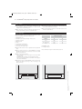
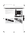
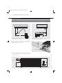
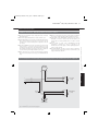
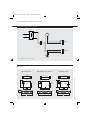
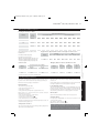
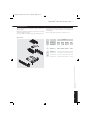
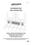
26690 Kickspace Manual for web_Layout 1 24/09/2013 10:07 Page 2
KICKSPACE® 500, 600, 600-12V & 800.
INSTALLATION, OPERATING, MAINTENANCE
AND AFTER SALES MANUAL.
Product Serial Number:
Please leave this manual with the end user.
Part Number: 1370054
01.01.2013 ISSUE 6
heatingthroughinnovation.
26690 Kickspace Manual for web_Layout 1 24/09/2013 10:07 Page 3
KICKSPACE ® 500, 600, 600-12V & 800
02
Contents
1.0
Safety Information
02
8.0
Water Connection
06
2.0
General Information
03
9.0
Electrical Connection
07
3.0
Heating System Design
03
10.0 Technical Data
08
4.0
Selection and Sizing for Heating
03
11.0 Operating Instructions
09
5.0
Location
04
12.0 Troubleshooting
10
6.0
Preparation
04
13.0 Maintenance
11
7.0
Fitting the KICKSPACE ®
05
1.0 Safety Information
The KICKSPACE® 500, 600 & 800 MUST NOT be installed in a bathroom
or other similar high humidity area.
WARNING: KICKSPACE® 500, 600 and 800 models must be earthed.
For the KICKSPACE ® 600-12V, a
fused electrical spur having 3mm
separation on all poles must be
provided in an easily accessible
position adjacent to the transformer.
Both the fused spur and the
transformer must not be positioned
in a bathroom or other similar high
humidity area.
If the supply cord to the
KICKSPACE ® models 500, 600 or
800 is damaged, it must be replaced
by the manufacturer, its service
agent or similar qualified persons in
order to avoid a hazard.
If the supply cord or outlet cord
to the KICKSPACE ® 600-12V
transformer is damaged, the
transformer must be replaced by the
manufacturer, its service agent or
similar qualified persons in order to
avoid a hazard.
This appliance can be used by
children aged from 8 years and
above and persons with reduced
physical or mental capabilities or
lack of experience and knowledge if
they have been given supervision or
instruction concerning the use of the
appliance in a safe way and
understand the hazards involved.
Children shall not play with the
appliance. Cleaning and user
maintenance shall not be made by
children unless they are older than 8
years and supervised.
KICKSPACE 500, 600, 600-12V & 800 INSTALLATION & MAINTENANCE MANUAL
01.01.2013 ISSUE 6
For MYSON KICKSPACE® 500, 600
& 800, a fused (3A) electrical
spur with a switch having 3mm
separation on all poles must be
provided in an easily accessible
position adjacent to the unit.
26690 Kickspace Manual for web_Layout 1 24/09/2013 10:07 Page 4
KICKSPACE ® 500, 600, 600-12V & 800
Children of less than 3 years should
be kept away from the unit unless
continuously supervised.
Children aged from 3 years and less
than 8 years shall only switch on / off
the appliance provided that it has
2.0
been placed or installed in its
normal operating position and they
have been given supervision or
instruction concerning use of the
appliance in a safe way and
understand the hazards involved.
Children aged from 3 years and less
than 8 years shall not plug in, clean
the appliance or perform user
maintenance.
3.0
Keep the appliance and its cord out
of reach of children aged less than 8
years.
1.0
(continued...)
4.0
1.0 Safety Information
03
2.0 General Information
l This MYSON KICKSPACE ® fan convector is designed for
installation in the cavity beneath kitchen cupboards on the
vacant floor space, or other similar locations.
l No rear access shall be available to the unit after installation.
l The KICKSPACE® should only be used on closed circulation,
two pipe, pump assisted central heating systems.
l Before proceeding with the installation, the heating system
design must be considered and the unit correctly sized to
meet the heat loss requirements of the room.
l Flexible hoses with integral isolating valves are supplied to
allow easy installation and future access for maintenance.
l KICKSPACE® is supplied with integral controls including fan
speed selector and summer/winter switch.
l In heating mode a low limit thermostat prevents the fan from
operating if the heating system water temperature is below
32°C.
l In summer mode the fan can be operated to circulate a flow
of air without any heat supply.
l The KICKSPACE ® 600-12V is supplied with a separate 12V
transformer that enables the unit to be fitted in a bathroom.
Both the unit and the transformer must be positioned in
accordance with local and national regulations.
3.0 Heating System Design
For optimum fan convector heating performance the system
must be capable of providing sufficient hot water through the
heat exchanger. This means that:
1. The minimum pipe size from boiler to fan convector must be
at least 15mm. Microbore pipe MUST NOT be used.
2. Where the unit is fitted on to a system with other emitters a
separate circuit for the fan convector should be considered
to provide adequate water flow.
3. The system water must be above 32°C for fan to switch on.
Performance will depend on the water temperature at the coil
and the flow through the coil.
4. This unit is NOT suitable for one-pipe systems.
5. Optimum performance will require effective balancing of the
whole system.
6. This unit must not be used to replace a radiator in an existing
system unless an adequate flow of water can be guaranteed.
4.0 Selection and Sizing for Heating
l Heat output performance is given in the Technical Data
section of this manual.
l Since KICKSPACE® units are supplied with fan speed control
it is important to size the unit to match the calculated heat
loss requirements of the room with the unit operating at the
low fan speed.
l The higher fan speed can then be used for more rapid
heating from cold in extreme conditions.
KICKSPACE 500, 600, 600-12V & 800 INSTALLATION & MAINTENANCE MANUAL
01.01.2013 ISSUE 6
This fan convector must be fitted on a two pipe, pumped
circulation heating system.
26690 Kickspace Manual for web_Layout 1 24/09/2013 10:07 Page 5
04
KICKSPACE ® 500, 600, 600-12V & 800
5.0 Location
l This KICKSPACE ® unit is designed for installation in the
cavity beneath cupboards in kitchens or other similar
locations on the vacant floor space.
l When installed in a kitchen consideration should be given to
storage of perishable goods in the cupboard above.
l A minimum of 25mm clear headroom is required above the
top of the KICKSPACE® when fitted.
l The unit should be mounted on a clean and level floor area
under the cupboard base.
6.0 Preparation
Before proceeding with the installation, unpack the carton
contents and check against the checklist below:
1.
KICKSPACE®
unit.
2. Flexible hoses including isolating valves (1 pair).
3. Instruction manual.
4. Warranty card.
5. Grille.
6. Screw fixing kit (with grille).
7. Transformer (12V model only).
Dimensions (mm)
Model
A
B
500
466
93
600 & 600-12V
520
93
800
573
93
A = Width of cutout
8. Connector (12V model only).
B = Height of cutout
l A clean and level floor area is required under the cupboard
base.
Note: unit dimensions given in Technical Data section 10.
l Floor mounting (see Fig. 1a) - The KICKSPACE ® is normally
fitted directly onto the floor and the base of the unit is fitted
with four mounting feet.
l Plinth mounting (see Fig. 1b) • As an alternative to floor mounting the unit may be fitted
into the plinth.
• A suitable support must be securely fitted to the floor.
• The top of the support must be level with the lower edge of
the cut-out when fitted.
A
A
B
B
Fig. 1a Plinth opening - floor mounting
Fig. 1b Plinth opening - plinth mounting
KICKSPACE 500, 600, 600-12V & 800 INSTALLATION & MAINTENANCE MANUAL
01.01.2013 ISSUE 6
l Decide the position of the KICKSPACE®, mark out and cut the
plinth to the dimensions of Fig. 1a (floor mounting) or 1b
(plinth mounting).
26690 Kickspace Manual for web_Layout 1 24/09/2013 10:08 Page 6
KICKSPACE ® 500, 600, 600-12V & 800
05
7.0 Fitting the KICKSPACE ®
l Position the KICKSPACE® under the cupboard in the required
location, with the front edge just behind the line of the plinth.
l Ensure that the flexible hoses are not kinked and that the
electrical cord is not in contact with hot surfaces.
l Replace the plinth and bring the KICKSPACE ® forward into
the opening so the front edge projects 8mm through the
plinth (see Fig. 2).
l Align the grille and secure it to the unit with two screws
supplied (use the shorter screws). (See Fig. 3).
l Secure the unit/grille to the plinth with two screws supplied
(use the longer screws). (See Fig. 3).
l Complete the electrical installation, switch on and test the
KICKSPACE® (see Fig. 4).
5.0
Top view of unit
8mm projection
6.0
Fig. 2
Summer/Winter switch
7.0
Front view of unit
Grille securing screws
Switch for fan
Boost
Off
Normal
Unit securing screws
Fig. 4
KICKSPACE 500, 600, 600-12V & 800 INSTALLATION & MAINTENANCE MANUAL
01.01.2013 ISSUE 6
Fig. 3
26690 Kickspace Manual for web_Layout 1 24/09/2013 10:08 Page 7
06
KICKSPACE ® 500, 600, 600-12V & 800
8.0 Water Connection
Pipework must be positioned correctly to ensure flexible hoses are not kinked when installed (see Figs. 5a
& 5b). Only use the hose sets supplied with this unit. Do not use old or alternative hose sets.
WALL
WALL
250
300
400
100
Fig. 5a Left hand view - suggestion only
Fig. 5b Right hand view - suggestion only
l Connect valve ends of the flexible pipes to the KICKSPACE ®.
Flexible pipes
Note: The direction of the arrows on the valves are not
significant in this application (see Fig. 6).
Isolating valves
l Open valves fully, check pipe connections for leaks and vent
the heat exchanger. A vent screw is provided to vent the heat
exchanger (see Fig. 7).
Air vent screw
Fig. 7
KICKSPACE 500, 600, 600-12V & 800 INSTALLATION & MAINTENANCE MANUAL
01.01.2013 ISSUE 6
Fig. 6
26690 Kickspace Manual for web_Layout 1 24/09/2013 10:08 Page 8
KICKSPACE ® 500, 600, 600-12V & 800
07
9.0 Electrical Connection
l The electrical installation must comply with local or national
wiring regulations.
l Remote Control Switch - A remote control switch is available as
an accessory, and if required should be wired at this stage.
l This unit is supplied fitted with a 2 metre 0.75mm2 cord.
l If the supply cord to KICKSPACE® models 500, 600 or 800 is
damaged, it must be replaced by the manufacturer, its
service agent or similar qualified persons in order to avoid a
hazard.
l For KICKSPACE® 500, 600 and 800, a fused (3A) electrical spur
with a switch having 3mm separation on all poles must be
provided in an easily accessible position adjacent to the unit
(see Fig. 8).
l For the KICKSPACE® 600-12V, a fused electrical spur having
3mm separation on all poles must be provided in an easily
accessible position adjacent to the transformer. Both the fused
spur and the transformer must not be positioned in a bathroom
or other similar high humidity installation (see Fig. 9).
l Room Thermostat - If a remote room thermostat is required,
wire it into the fused spur at this stage (not KICKSPACE® 600
12V).
l If the supply or outlet cord to KICKSPACE® 600-12V
transformer is damaged, it must be replaced by the
manufacturer, its service agent or similar qualified persons in
order to avoid a hazard.
l For the KICKSPACE® 600-12V, a connector block is supplied to
connect the low voltage supply from the transformer to the
supply cord fitted to the unit.
Do not energise the electrical supply until the remaining stages of the installation have been completed.
MOTOR
y
r
8.0
bl
KICKSPACE 500, 600, 600-12V & 800 INSTALLATION & MAINTENANCE MANUAL
01.01.2013 ISSUE 6
WARNING: KICKSPACE® 500, 600 and 800 models must be earthed.
L
N
br
Fan Selector
Switch
bl
9.0
g/y
Chassis
Earth
Summer/Winter
Switch
bl
bl
LOW LIMIT
THERMOSTAT
Fig. 8 KICKSPACE® 500, 600 & 800 wiring diagram
26690 Kickspace Manual for web_Layout 1 24/09/2013 10:08 Page 9
08
KICKSPACE ® 500, 600, 600-12V & 800
9.0 Electrical Connection
(continued...)
Transformer
L
MOTOR
Mains Supply 240V
br
N
bl
br
Fan Selector
Switch
bl
Connector
Block
Summer/Winter
Switch
LOW LIMIT
THERMOSTAT
Fig. 9 KICKSPACE® 600-12V wiring diagram
10.0 Technical Data
Dimensions
KICKSPACE ® 600 & 600-12V
View on arrow
Cable Entries
54
24
View on arrow
View on arrow
93
67
Cable Entries
54
12
24
Top view
12
24
Cable Entry
25
Mains Cable
309
309
Cable Entry
Cable Entry
25
447
376
FRONT GRILLE
FRONT GRILLE
101
101
550
25
129
129
322
496
36
Mains Cable
129
101
12
82
36
FRONT GRILLE
93
67
Top view
82
Mains Cable
Cable Entries
54
93
67
Top view
82
36
309
KICKSPACE ® 800
603
KICKSPACE 500, 600, 600-12V & 800 INSTALLATION & MAINTENANCE MANUAL
01.01.2013 ISSUE 6
KICKSPACE ® 500
26690 Kickspace Manual for web_Layout 1 24/09/2013 10:08 Page 10
KICKSPACE ® 500, 600, 600-12V & 800
10.0 Technical Data
09
(continued...)
Heating Performance Data
20°
Temperature Difference (°C)
Heat Output (Watts)
Heat Output (Btu/h)
30°
40°
50°
60°
20°
30°
40°
50°
Normal
393
566
733
896
1056
1340
1930
2501
3057
3603
Boost
447
683
923
1166
1412
1524
2331
3150
3980
4817
Normal
467
729
1000
1278
1562
1592
2486
3412
4361
5330
Boost
607
939
1279
1625
1977
2072
3203
4363
5545
6744
Normal
747
1077
1396
1707
2012
2550
3675
4763
5824
6864
Boost
845
1289
1738
2192
2649
2885
4397
5930
7478
9039
Normal
467
729
1000
1278
1562
1592
2486
3412
4361
5330
Boost
607
939
1279
1625
1977
2072
3203
4363
5545
6744
600 - 12V
Heat outputs tested in accordance with
BS 4856 Part 1.
Flow Rate: 340 ltr/h (75 gal/h).
Approximate Hydraulic Resistance through Fan Convectors
Litres/h
Flow Rate Correction Factors:
455 ltr/h (100 gal/h) multiply output by 1.03.
227 ltr/h (50 gal/h) multiply output by 0.96.
113 ltr/h (25 gal/h) multiply output by 0.85.
455
340
227
113
Sound Levels
Model
kPa
mm wg
500
600
600-12V
800
500
600
600-12V
800
788
488
231
82
1046
625
326
95
1046
625
326
95
911
544
258
82
7.7
4.8
2.3
0.8
10.3
6.1
3.2
0.9
10.3
6.1
3.2
0.9
8.9
5.3
2.5
0.8
Weight, Water Content and Motor Power
Sound Pressures at 2.5m (dBA)
Model
Motor
Power (W)
Water
Content (l)
Unit Weight
(kg)
38.1
500
25
0.26
4.3
37.2
600
40
0.30
5.0
26.4
32.7
600-12V
40
0.30
7.9 *
28.5
49.8
800
40
0.34
5.5
Normal
Boost
500
25.7
600
26.4
600-12V
800
Sound levels tested in accordance with EN 23741.
*Includes transformer.
11.0 Operating Instructions
This unit is controlled by the switches on the front of the unit, or
by means of the wall mounted remote switching kit if fitted.
The fan speed can be set to boost by switching the fan speed
switch to II.
Ensure the electricity supply is switched on.
A low speed setting is recommended for normal operation with
the higher speeds for boost heating when required.
Heating Mode
The fan will only operate when
Low Limit Operation
• The central heating boiler is on
• The pump is running
• The system water temperature is greater than 32°C.
The low limit thermostat fitted to the KICKSPACE® will ensure
that the fan stops after the heating system is switched off and
the water flow stops. If left in an operating position the unit will
automatically restart when the heating system is reheated.
Ensure boiler is on, and set timer, boiler controls and room
thermostats as necessary.
Off Position
•
•
•
•
Turn room thermostat to a high setting.
Set summer - winter switch to
Set fan speed control to position I.
The unit will now run on low fan speed.
Performance will depend on the water temperature at the coil
and the flow through the coil.
Temperature Control
The room thermostat setting should be gradually adjusted to
obtain the desired temperature.
KICKSPACE 500, 600, 600-12V & 800 INSTALLATION & MAINTENANCE MANUAL
01.01.2013 ISSUE 6
800
9.0
600
10.0
500
60°
Set the fan speed selector switch to the off (O) position.
Summer Mode
If required, the KICKSPACE ® can be used in Summer for air
circulation without heat.
Set summer - winter switch to
Adjust fan speed to required setting.
If a remote control switch is fitted, the fan switch on
the unit will be inoperative. Refer to the instructions
supplied with the remote control switch for details.
11.0
Fan
Speed
Model
26690 Kickspace Manual for web_Layout 1 24/09/2013 10:08 Page 11
10
KICKSPACE ® 500, 600, 600-12V & 800
12.0 Troubleshooting
installer or MYSON Service. Before calling your installer or
MYSON Service, please carry out the checks listed below.
Once installed this fan convector becomes an integral part of a
complete heating system that includes boiler, pump, other
emitters such as radiators and fan convectors, and a number of
heating controls, dependent on system complexity. An apparent
problem with this unit may be the result of system controls being
incorrectly set and can be solved easily without calling out your
Problem
Note: If you call out MYSON Service to a fault detailed below,
or to repair a fault caused by incorrect use, a call out charge will
be made.
Possible Causes
Remedy
Unit switched off
Turn on
Room thermostat not calling for heat
Turn up room thermostat
Unit not switched on at fused spur
Switch on at spur
Fuse blown at fused spur
Replace fuse
Unit isolating valves shut
Open valves
Water temperature reaching
fan convector below 32°C
Check boiler - Programmer ON
Central heating
Mode - No Fan
Boiler ON and set to high with
central heating pump running
Note: Operation of fan can be checked by
switching to summer setting
Remote control switched off (if fitted)
Switch to heating mode
Low water temperature to unit
Turn up boiler thermostat
Poor water flow
Vent air from heating system
Central Heating Mode
- poor heating
performance and/or
unit cycles on
low limit thermostat
If the fan convector is still faulty after checking the above, call your installer or MYSON Service.
For optimum performance, this unit must be correctly sized to
match the heat loss requirements of the space it is required to
heat, and the heating system must be correctly designed to
provide adequate flow of hot water to the unit (see Section 2).
If the recommendations in Section 2 are not followed,
problems may arise as detailed below.
Problem
Possible Causes
Poor heating
performance
Unit incorrectly sized for heat loss of room
Boiler thermostat set too low
Lack of flow to fan convector
Poor heating
performance
(unit may cycle on
low limit thermostat)
Pump set on low setting
Isolating valves not fully open
System incorrectly balanced with unit starved of hot water flow
Pipe sizing to unit too small
KICKSPACE 500, 600, 600-12V & 800 INSTALLATION & MAINTENANCE MANUAL
01.01.2013 ISSUE 6
Common Installation Faults
26690 Kickspace Manual for web_Layout 1 24/09/2013 10:08 Page 12
KICKSPACE ® 500, 600, 600-12V & 800
11
13.0 Maintenance
Before undertaking any maintenance activity isolate the
electrical supply.
Maintenance should be restricted to occasional removal of dust
and lint around the front grille.
This should involve internal cleaning of the heat exchanger using
a soft brush or vacuum cleaner, taking care not to damage fan or
heat exchanger.
Please see after sales service details on the back cover.
This unit should be serviced periodically by a competent person.
Spare Parts
Part No.
Item
5
4
KS 500
KS 600
KS 800
KS 600
12V
1
Switch, 3 Way
1300025
2
Switch, 2 Way
1300024
3
Wiring Harness
4
Motor/Fan
5
Low Limit
Thermostat
Not
Shown
Transformer
N/A
1320028
Not
Shown
Transformer
Connector Block
N/A
1396003
3000021
1200049
1200050
3000056
1200060
1200061
1260007
12.0
KICKSPACE 500, 600, 600-12V & 800 INSTALLATION & MAINTENANCE MANUAL
01.01.2013 ISSUE 6
3
13.0
2
1
Description
26690 Kickspace Manual for web_Layout 1 24/09/2013 10:07 Page 1
MYSON Eastern Avenue, Team Valley, Gateshead, Tyne & Wear NE11 0PG, UK
T: 0845 402 3434, F: 0191 491 7568, [email protected], www.myson.co.uk
Product code and
serial number location
After Sales Service:
MYSON Service, Somerden Road, Hull, East Yorkshire HU9 5PE
T: 01482 713927, F: 01482 789056, [email protected]
Spare parts and technical help on all Convector products are available from MYSON Service.
01.01.2013 ISSUE 6
heatingthroughinnovation.