1
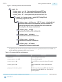
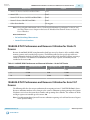
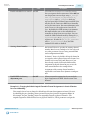
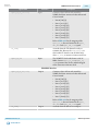
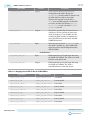
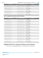
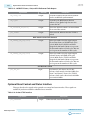
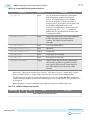
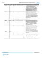
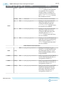
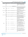
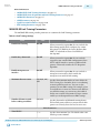
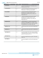
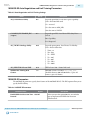
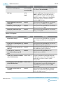
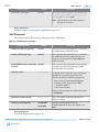
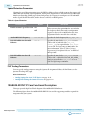
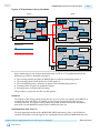
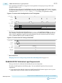
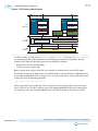
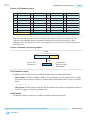
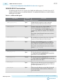
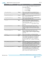
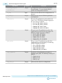
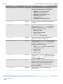
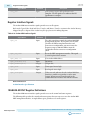
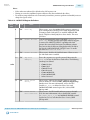
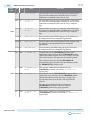
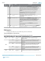
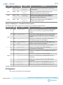
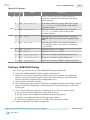
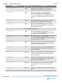
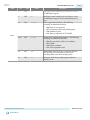
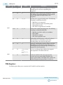
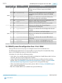
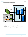
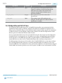
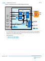
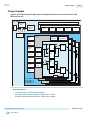
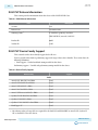
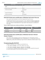
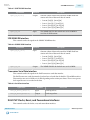
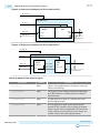
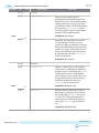
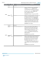
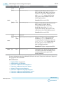
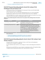
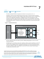
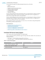
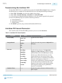
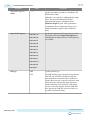
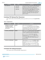
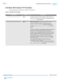
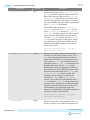
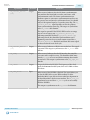
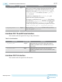
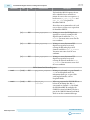
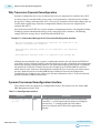
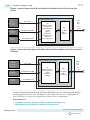
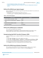
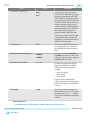
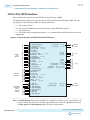
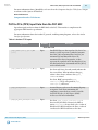
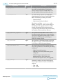
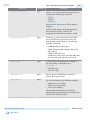
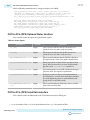
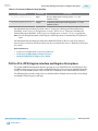
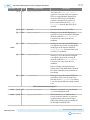
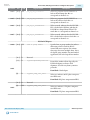
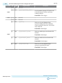
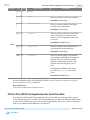
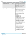
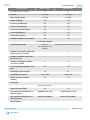
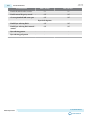
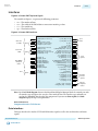
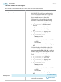
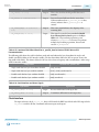
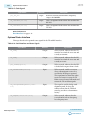
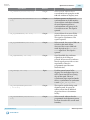
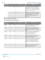
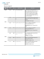
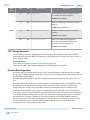
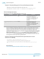
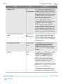
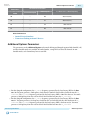
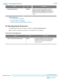
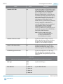
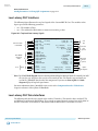
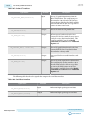
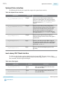
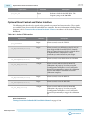
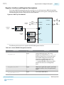
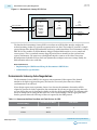
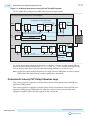
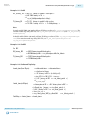
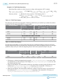
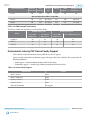
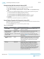
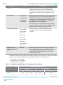
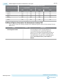
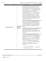
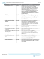
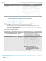
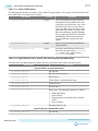
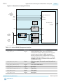
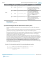
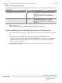
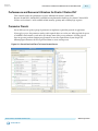
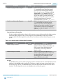
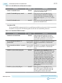
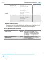
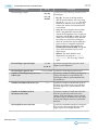
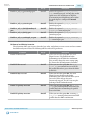
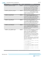
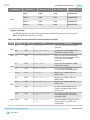
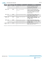
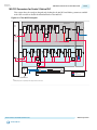
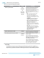
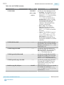
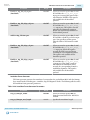
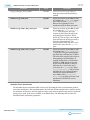
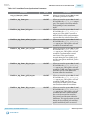
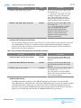
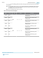
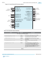
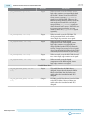
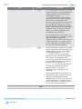
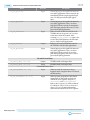
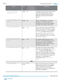
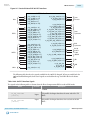
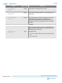
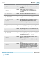
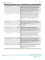
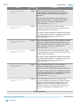
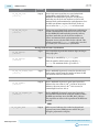
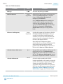
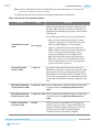
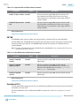
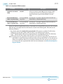
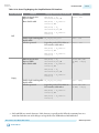
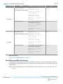
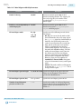
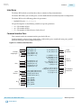
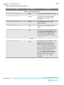
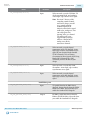
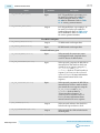
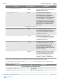
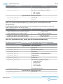
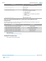
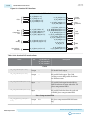
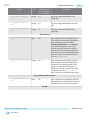
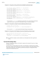
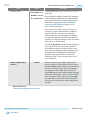
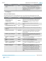
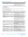
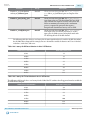
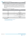
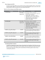
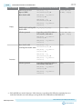
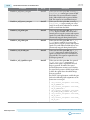
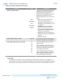
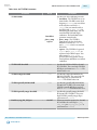
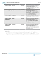
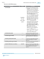
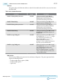
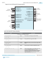
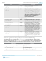
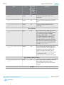
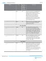
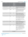
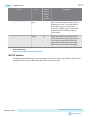
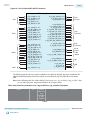
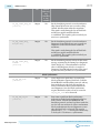
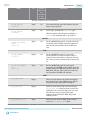
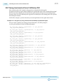
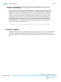
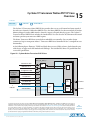
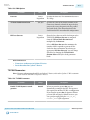
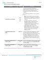
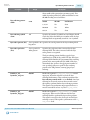
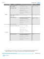
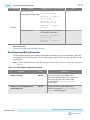
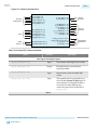
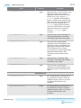
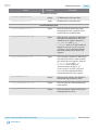
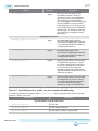
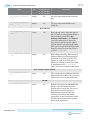
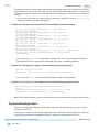
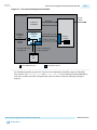
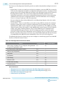
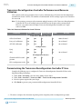
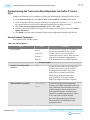
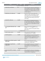
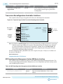
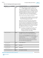
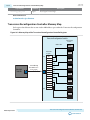
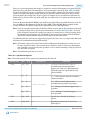
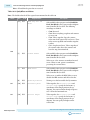
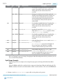
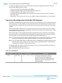
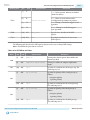
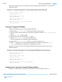
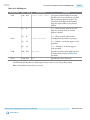
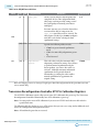
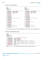
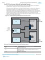
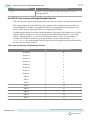
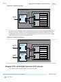
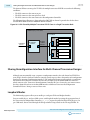
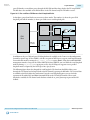
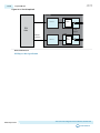
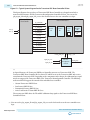
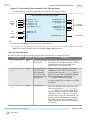
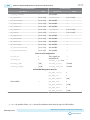
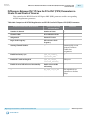
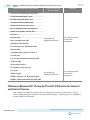
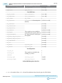
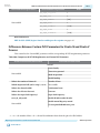
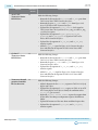
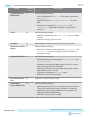
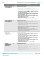
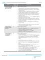
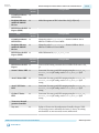
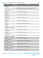
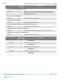
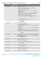
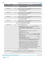
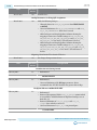
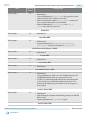
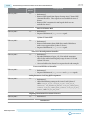
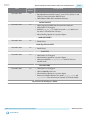
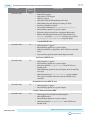
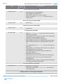
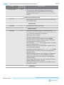
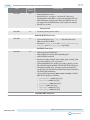
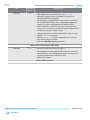
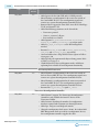
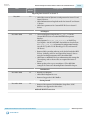
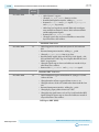
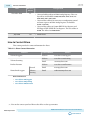
UG-01080
2015.01.19
Dynamic Reconfiguration for Deterministic Latency PHY
Word Addr
0x085
Bits
R/W
Register Name
[31:4]
RW
pcs8g_rx_wa_control
[3]
RW
rx_bitslip
[2]
RW
rx_bytereversal_enable
[1]
RW
rx_bitreversal_enable
[0]
RW
rx_enapatternalign
11-27
Description
Reserved.
Every time this register transitions
from 0 to 1, the RX data slips a single
bit. To block: Word aligner.
When set, enables byte reversal on
the RX interface. To block: Byte
deserializer RX Phase Comp FIFO.
When set, enables bit reversal on the
RX interface. To block: Word
aligner.
When set in manual word alignment
mode, the word alignment logic
begins operation when this bit is set.
To block: Word aligner.
Related Information
Loopback Modes on page 16-58
Dynamic Reconfiguration for Deterministic Latency PHY
Dynamic reconfiguration compensates for circuit variations due to process, voltage, and temperature
(PVT).
These process variations result in analog voltages that can be offset from required ranges. The calibration
performed by the dynamic reconfiguration interface compensates for variations due to PVT.
Each channel and each TX PLL has a separate dynamic reconfiguration interfaces. The MegaWizard PlugIn Manager provides informational messages on the connectivity of these interfaces. The following
example shows the messages for a single duplex channel.
Although you must initially create a separate reconfiguration interface for each channel and TX PLL in
your design, when the Quartus II software compiles your design, it reduces the number of reconfiguration
interfaces by merging reconfiguration interfaces. The synthesized design typically includes a reconfigura‐
tion interface for at least three channels because three channels share an Avalon-MM slave interface
which connects to the Transceiver Reconfiguration Controller IP Core. Conversely, you cannot connect
the three channels that share an Avalon-MM interface to different Transceiver Reconfiguration
Controller IP Cores. Doing so causes a Fitter error. For more information, refer to Transceiver Reconfigu‐
ration Controller to PHY IP Connectivity.
Example 11-5: Information Messages for the Transceiver Reconfiguration Interface
PHY IP will require 2 reconfiguration interfaces for
connection to the external reconfiguration controller.
Reconfiguration interface offset 0 is connected to the
transceiver channel.
Reconfiguration interface offset 1 is connected to the
transmit PLL.
Deterministic Latency PHY IP Core
Send Feedback
Altera Corporation