Download ManualV3 - Electromate
Transcript
Galil Programming Manual Version 3.0 . © 2003 Electromate Industrial Sales Ltd. www.electromate.com [email protected] . TOLL FREE PHONE (877)SERVO98 TOLL FREE FAX (877)SERVO99 TABLE OF CONTENTS Program Flow: Programming Instruction Format........................................................................ 6 Tuning Parameters............................................................................................. 7 Programming Environments.............................................................................14 Interrogating Status Commands ...................................................................... 50 Conditional Statements .................................................................................... 51 Loops ............................................................................................................... 52 Trippoints ......................................................................................................... 53 Automatic Subroutines ..................................................................................... 74 Multitasking .................................................................................................... 141 Motion Programming: Tuning Your Servo System ................................................................................ 8 System Set-Up .................................................................................................10 S Curve Profiling .............................................................................................. 12 Operation Under Torque Limit..........................................................................1 3 Motion Control Modes ...................................................................................... 15 Independent Axis Positioning........................................................................... 16 Independent Motion Commands ...................................................................... 17 Stored Programs .............................................................................................. 19 Jogging............................................................................................................. 20 Linear Interpolation .......................................................................................... 21 Controlling Linear Interpolation From A Host Program………………………………..23 Coordinated Motion Sequences....................................................................... 25 Converting To User Units................................................................................. 28 Programming In User Units.............................................................................. 30 Specifying Linear Segments ............................................................................ 31 Specifying Arc Seqments ................................................................................. 32 Circular Interpolation ........................................................................................ 33 Contour Mode .................................................................................................. 35 Contouring........................................................................................................ 43 Gearing Resolution……………………………………………………………………………………..…..48 Mathematic And Functional Expressions ......................................................... 49 I/O Interface ..................................................................................................... 57 Input/Output Interface ...................................................................................... 59 Uncommitted Inputs ......................................................................................... 60 Input Interrupt Functions/Subroutines .............................................................. 61 Using IF, ELSE And ENDIF Constructs ........................................................... 6 4 Uncommitted Outputs ...................................................................................... 65 Analog Inputs ................................................................................................... 66 Input Of Data.................................................................................................... 67 Output Of Data.................................................................................................68 Control Variables.............................................................................................. 69 ELECTROMATE INDUSTRIAL SALES LTD. TOLL FREE PHONE (877) SERVO98 • TOLL FREE FAX (877) SERVO99 [email protected] • WWW.ELECTROMATE.COM Control Variables and Offset ............................................................................ 72 Symbolic Variables........................................................................................... 73 Special Labels.................................................................................................. 75 Displaying Binary Numbers……………………………………………………………………………..76 Limit Switch Routines....................................................................................... 77 Electronic Gearing.......................................................................................... 103 Tangent Motion .............................................................................................. 130 Proportional Motion ........................................................................................ 131 Infinite Array Recording……………………………………………………………….………………..147 Application Example: Linear Interpolation .......................................................................................... 22 XY Racetrack ................................................................................................... 27 Converting To User Units................................................................................. 29 Circular Interpolation ........................................................................................ 34 Spiral Trajectory ............................................................................................... 37 Creating A Spiral Motion Path……………………………………………………………..………….40 Contour Mode .................................................................................................. 44 Elliptical Motion ................................................................................................ 45 Elliptical Motion With Gearing .......................................................................... 46 Spiral Motion With Gearing .............................................................................. 47 Trippoints ......................................................................................................... 54 Input Interrupt................................................................................................... 62 Starting Motion From A Switch Input................................................................ 6 3 Bouncing off A Limit Switch…………………………………………………………………………….78 Making Jumps Out Of Automatic Subroutines ................................................. 80 Stop At A Mechanical Limit .............................................................................. 81 Pause Motion ................................................................................................... 82 Motion Complete Timeout ................................................................................ 83 Correcting Wrong Operator Input Data ............................................................ 84 Using The Term-H/P Pendant……………………………………...…………………………….…. 85 Point-To-Point Move ........................................................................................ 87 Pick And Place ................................................................................................. 88 Press Fitting Machine....................................................................................... 90 Autostart Cut To Length ................................................................................... 92 Position Follower I............................................................................................ 95 Position Follower II........................................................................................... 96 Position Follower III.......................................................................................... 97 Continuous Move ........................................................................................... . 98 Generating A Helical Motion Profile………………………………………………………..…….. 99 Helical Motion.................................................................................................102 Rotating Knife ................................................................................................ 104 Rotating Knife 2 ............................................................................................. 106 Web Tension Control ..................................................................................... 108 Web Processing............................................................................................. 111 ELECTROMATE INDUSTRIAL SALES LTD. TOLL FREE PHONE (877) SERVO98 • TOLL FREE FAX (877) SERVO99 [email protected] • WWW.ELECTROMATE.COM Continuous Cutting Of Moving Webs By Waterjet ......................................... 114 Web Cutting With Fixed Cut Length............................................................... 116 Tension Control By Electronic Gearing .......................................................... 117 Gearing Acceleration...................................................................................... 119 Synchronizing Two Conveyor Belts With Trapezoidal Velocity Correction..... 121 Gearing Acceleration (Superimposed Profile Method)……………………...……122 Wire Cutter..................................................................................................... 124 Variable Length Ecam Motion…………………………………………………….125 Cutting Material On Moving Belt..................................................................... 127 Flying Shears ................................................................................................. 128 Constant Force............................................................................................... 133 Joystick Control.............................................................................................. 135 Joystick With Nonlinear Function ................................................................... 136 Backlash Compensation ................................................................................ 138 Teach Mode ................................................................................................... 139 Multitasking .................................................................................................... 141 Using Multi-tasking To Produce Waveform Output ........................................ 143 Arrays............................................................................................................. 144 Array Data Storage ........................................................................................ 150 Method To Increase Array Space .................................................................. 151 Recording....................................................................................................... 154 Record And Play Back ................................................................................... 157 Feedrate Override .......................................................................................... 160 Variable Feedrate........................................................................................... 162 Routine For Monitoring Encoder Failure…………………………………………164 Step Motor Monitor Routine……………………………………………………….166 Step Motor Position Maintenance………………………………………………...166 Step Motor In Position Routine……………………………………………………167 Step Motor Stall Detect…………………………………………………………….167 Appendices: DMC-1200/13x8/1600/1700/1800/2000/2100 Series Controllers................... 168 DMC-1410/1411/1412/1414 Series Controller.………………………………….169 DMC-1415/1416/1425 Series Controller……...………………………………….170 DMC-3425 Series Controller…………...………………………………………….171 DMC-1000/1300/1500 Series Controller ........................................................ 172 DMC-700 Series Controller ............................................................................ 173 DMC-600 Series Controller ............................................................................ 174 DMC-400 Series Controller ............................................................................ 175 ELECTROMATE INDUSTRIAL SALES LTD. TOLL FREE PHONE (877) SERVO98 • TOLL FREE FAX (877) SERVO99 [email protected] • WWW.ELECTROMATE.COM Disclaimer This guide is designed to assist users in understanding the Galil motion controller programming language, and by no means, should serve to replace the factory published Hardware User Manuals. This Manual should be used in conjunction with all other factory supplied documentation. The production of this Reference Guide is a culmination of 15 years of Galil programming experience by the staff of Electromate. Considering the multitude of potential programming solutions, this guide should by no means serve as a complete programming guide, nor do we guarantee it’s syntax accuracy. Numerous application examples throughout this Reference Guide are specific to certain advanced level controllers, so please refer to the Command Summary Appendices for appropriate controller selection. No part of this Reference Guide may be reproduced by any means, nor transmitted, nor translated without written permission from Electromate Industrial Sales Ltd. Errors and omissions excepted. Subject to change without notice. © 1999-2003 Electromate Industrial Sales Ltd. ELECTROMATE INDUSTRIAL SALES LTD. TOLL FREE PHONE (877) SERVO98 • TOLL FREE FAX (877) SERVO99 [email protected] • WWW.ELECTROMATE.COM Programming Instruction Format •Two-letter, English-like commands • Must be upper case (CAP LOCK on) • Commas separate X, Y, Z, W parameters • Multiple commands per line allowable if separated by semicolon (i.e. PR50;SP10;BG;TPX) • All Galil controllers perform quadrature decoding of the encoder input signal to provide 4 X interpolation IE. the command to move a motor with a 500 ppr resolution encoder is PR 2000 • Example: TP X ST XW SP 100,200 PR,,,4000 BG Tell position of X axis only Stop X and W axes Set Speed for X and Y axes Set position for W axis only Begin motion on all axes 6 ELECTROMATE INDUSTRIAL SALES LTD. TOLL FREE PHONE (877) SERVO98 • TOLL FREE FAX (877) SERVO99 [email protected] • WWW.ELECTROMATE.COM Tuning Parameters Designates the proportional constant in the controller filter KP Designates the derivative constant in the controller filter KD Sets the integral gain of the control loop KI Sets the acceleration feedfordward coefficient FA Sets the velocity feedforward coefficient FV Sets a bias voltage in the motor command output OF Smoothing time constant which filters the acceleration IT / VT & deceleration functions in independent/vector moves Sets the gain of the control loop GN Sets the compensating zero function in the control loop ZR Sets the integral gain of the control loop KI Rule of Thumb: Tuning is a ‘trial and error’ processFor systems with high oscillation, decrease GN and increase ZR in tandem or decrease KP and increase KD in tandem For systems with underdamped conditions, increase GN and decrease ZR in tandem or increase KP and decrease KD in tandem For systems with poor accuracy, gradually increase KI For systems with high frequency ringing, increase KD A typical tuning parameter set-up will have a KD of 5 to 10 times KP, and a KI =1 (or KI=2) 7 ELECTROMATE INDUSTRIAL SALES LTD. TOLL FREE PHONE (877) SERVO98 • TOLL FREE FAX (877) SERVO99 [email protected] • WWW.ELECTROMATE.COM Motion Programming: Tuning Your Servo System Adjusting the tuning parameters are required when using servo motors (standard or sinusoidal commutation). The system compensation provides fast and accurate response and the following presentation suggests a simple and easy way for compensation. More advanced design methods are available with software design tools from Galil, such as the Servo Design Kit (SDK software) The filter has three parameters: the damping, KD; the proportional gain, KP; and the integrator, KI. The parameters should be selected in this order. To start, set the integrator to zero with the instruction Instruction KI 0 (CR) Interpretation Integrator gain and set the proportional gain to a low value, such as Instruction KP 1 (CR) Interpretation Proportional gain Instruction KD 100 (CR) Interpretation Derivative gain For more damping, you can increase KD (maximum is 4095). Increase gradually and stop after the motor vibrates. A vibration is noticed by audible sound or by interrogation. If you send the command Instruction TE X (CR) Interpretation Tell error a few times, and get varying responses, especially with reversing polarity, it indicates system vibration. When this happens, simply reduce KD. Next you need to increase the value of KP gradually (maximum allowed is 1023). You can monitor the improvement in the response with the Tell Error instruction Instruction KP 10 (CR) Interpretation Proportion gain 8 ELECTROMATE INDUSTRIAL SALES LTD. TOLL FREE PHONE (877) SERVO98 • TOLL FREE FAX (877) SERVO99 [email protected] • WWW.ELECTROMATE.COM Instruction TE X (CR) Interpretation Tell error As the proportional gain is increased, the error decreases. Again the system may vibrate if the gain is too high. In this case, reduce KP. Typically, KP should not be greater than KD/4 to KD/10 (Only when the amplifier is configured in the current mode). Finally, to select KI, start with zero value and increase it gradually. The integrator eliminates the position error, resulting in improved accuracy. Therefore, the response to the instruction Instruction TE X (CR) Interpretation Tell error becomes zero. As KI is increased, its effect is amplified and it may lead to vibrations. If this occurs, simply reduce KI. Repeat tuning for the Y, Z and W axes. 9 ELECTROMATE INDUSTRIAL SALES LTD. TOLL FREE PHONE (877) SERVO98 • TOLL FREE FAX (877) SERVO99 [email protected] • WWW.ELECTROMATE.COM Motion Programming: System Set-up Here are a few examples for tuning and using your controller. These examples have remarks next to each command - these remarks must not be included in the actual program. This example assigns the system filter parameters, error limits and enables the automatic error shut-off. Instruction Interpretation KP10,10,10,10,10,10,10,10 Set gains for A, B, C, D, E, axes Set gains for A, B, C, D, E, and H axes Alternate method for setting gain on all axes Alternate method for setting X (or A) axis gain Alternate method for setting A (or X) axis gain KP10,10,10,10,10,10,10,10 KP*=10 KPX=10 KPA=10 The X, Y, Z and W axes can also be referred to as the A, B, C, and D axis. Instruction Interpretation’ OE 1,1,1,1,1,1,1,1 Enable automatic Off on Error function for all axes Set error limit for all axes to 1000 counts Set gains For A, B, C, D, E, and H axes Alternate method for setting gain on all axes Alternate method for setting X (or A) axis gain Alternate method for setting A Alternate method for setting Z axis gain ER*=1000 KP10,10,10,10,10,10,10,10 KP*=10 KPX=10 KPA=10 KPZ=10 10 ELECTROMATE INDUSTRIAL SALES LTD. TOLL FREE PHONE (877) SERVO98 • TOLL FREE FAX (877) SERVO99 [email protected] • WWW.ELECTROMATE.COM KPD=10 KPH=10 Alternate method for setting D axis gain Alternate method for setting H axis gain 11 ELECTROMATE INDUSTRIAL SALES LTD. TOLL FREE PHONE (877) SERVO98 • TOLL FREE FAX (877) SERVO99 [email protected] • WWW.ELECTROMATE.COM Motion Programming: Using the IT and VT Commands(S curve profiling): When operating with servo motors, motion smoothing can be accomplished with the IT and VT command. These commands filter the acceleration and deceleration functions to produce a smooth velocity profile. The resulting velocity profile, known as S curve, has continuous acceleration and results in reduced mechanical vibrations. The smoothing function is specified by the following commands: Instruction Interpretation IT x,y,z,w VT n Independent time constant Vector time constant The command, IT, is used for smoothing independent moves of the type JG, PR, PA and the command, VT, is used to smooth vector moves of the type VM and LM. The smoothing parameters, x,y,z,w and n are numbers between 0 and 1 and determine the degree of filtering. The maximum value of 1 implies no filtering, resulting in trapezoidal velocity profiles. Smaller values of the smoothing parameters imply heavier filtering and smoother moves. The following example on the next page illustrates the effect of smoothing. Note that the smoothing process results in longer motion time. Example - Smoothing Instruction Interpretation PR 20000 AC 100000 DC 100000 SP 5000 IT .5 BG X Position Acceleration Deceleration Speed Filter for S-curve Begin 12 ELECTROMATE INDUSTRIAL SALES LTD. TOLL FREE PHONE (877) SERVO98 • TOLL FREE FAX (877) SERVO99 [email protected] • WWW.ELECTROMATE.COM Motion Programming: Operation Under Torque Limit The magnitude of the motor command may be limited independently by the instruction TL. Instruction Interpretation TL 0.2 Set output limit of X axis to 0.2 volts Set X speed Start X motion JG 10000 BG X In this example, the X motor will probably not move since the output signal will not be sufficient to overcome the friction. If the motion starts, it can be stopped easily by a touch of a finger. Increase the torque level gradually by instructions such as Instruction TL 1.0 TL 9.98 Interpretation Increase torque limit 1 volt Increase torque limit to maximum, 9.98 volts The maximum level of 10 volts provides the full output torque. 13 ELECTROMATE INDUSTRIAL SALES LTD. TOLL FREE PHONE (877) SERVO98 • TOLL FREE FAX (877) SERVO99 [email protected] • WWW.ELECTROMATE.COM Programming Environments A variety of device drivers are available for most Galil controllers via the source code subdirectory located on the COM-Disk, specifically: • Visual Basic • C, C++ • DOS • Pascal, Turbo Pascal • BASIC • Windows 3.X/ 95/ 98/ NT/ 2000 and CE • QNX • OCX/ OLE Controls • DLL’S • Labview, Wonderware, Think And Do • Delphi, HP VEE, Linux A variety of translator software packages are also supported, including: CAD (any DXF file) File Conversion HPGL Code Conversion Visual Basic/ Active X ECAM DDE 14 ELECTROMATE INDUSTRIAL SALES LTD. TOLL FREE PHONE (877) SERVO98 • TOLL FREE FAX (877) SERVO99 [email protected] • WWW.ELECTROMATE.COM Motion Control Modes Independent move PR, PA Jog Mode JG Vector Mode - Linear and Circular VM Linear Interpolation LM Contour Mode CM Electronic Gearing GA Electronic CAM EA Elliptical Move ES Gantry Mode GM Tangential Move TN Homing Commands HM, FE, FI S-Curve Move IT, VT 15 ELECTROMATE INDUSTRIAL SALES LTD. TOLL FREE PHONE (877) SERVO98 • TOLL FREE FAX (877) SERVO99 [email protected] • WWW.ELECTROMATE.COM Motion Programming: Independent Axis Positioning • Motion between specified axes is independent • User specifies: PR or PA SP AC DC IT BG Relative or Absolute Position [counts] Slew speed [counts/sec] 2 Acceleration [counts/sec ] Deceleration S-Curve filter Begin • BG command begins motion • Can change SP, AC, DC during motion • Can change direction during motion • Example: Instruction PR 1000,4000 SP 2500,2500 AC 100000,100000 DC 50000,50000 BG XY Interpretation Specify relative position Specify slew speed Specify acceleration Specify deceleration Begin motion 16 ELECTROMATE INDUSTRIAL SALES LTD. TOLL FREE PHONE (877) SERVO98 • TOLL FREE FAX (877) SERVO99 [email protected] • WWW.ELECTROMATE.COM Motion Programming: Independent Motion Commands A motion controller can be “told” by a host computer to perform a move by any of the controlled motors. The most simple move is one with a trapezoidal velocity profile as illustrated below. This move is characterized by the parameters: distance, slew velocity, and acceleration and deceleration rates. VELOCITY SLEW SPEED ACCELERATION RATE DECELERATION RATE TIME Trapezoidal Velocity Profile The most basic form of specifying these motion parameters is by “units of position resolution.” For example, let the encoder resolution be 4000 counts per turn and suppose the objective is to rotate the motor one revolution along a trapezoidal velocity, with a total motion time of 0.3 sec with acceleration and deceleration times of 0.1 sec each. Simple calculation indicates that the slew velocity equals 5 revolutions per second and that both acceleration and deceleration rates 2 are 50 revolutions/sec . The motion parameters can be expressed in terms of units of resolution as a distance of 4000 counts, a slew velocity of 20,000 counts/sec, and acceleration and deceleration rates of 200,000 counts/sec2. The motion parameters must be transmitted from the host computer to the motion controller. The special instructions used by the controller, along with their interpretation, are given below. Instruction Interpretation PR 4000 SP 20000 AC 200000 DC 200000 BGX Relativedistance Speed rate Acceleration rate Deceleration rate Start motion of X motor 17 ELECTROMATE INDUSTRIAL SALES LTD. TOLL FREE PHONE (877) SERVO98 • TOLL FREE FAX (877) SERVO99 [email protected] • WWW.ELECTROMATE.COM All that is needed is that the host computer sends the characters indicated by the program shown above and the motion starts immediately. Another type of simple motion is the jog move. Here the motor is commanded to run indefinitely at a specified speed. The motion parameters in this case are limited to the speed, acceleration, and deceleration. These parameters can be expressed in units of resolution as illustrated below. Consider a system where the resolution of the encoder is 4000 counts/turn and where the motor is required to run at a speed of 600 rpm, or 10 revolutions/sec, and must accelerate to that speed over 100 msec. Simple calculations show that the speed rate is 40,000 counts/sec and that the acceleration rate is 400,000 counts/sec2. The instructions used to generate such a motion, along with their interpretations, are shown in following example. Instruction Interpretation JG 40000 AC 400000 BGX Jog speed Acceleration rate Start X motion 18 ELECTROMATE INDUSTRIAL SALES LTD. TOLL FREE PHONE (877) SERVO98 • TOLL FREE FAX (877) SERVO99 [email protected] • WWW.ELECTROMATE.COM Motion Programming: Stored Programs The instructions to execute the motion can be issued directly from the host computer or external operator interface, resulting in an immediate move. This mode, the immediate mode, requires the continuous involvement of the interface. This requirement is often undesirable because the host may have to perform other functions simultaneously. An alternative method is to combine several motion commands into a complete application program which is downloaded to the controller memory. This method reduces or eliminates the involvement of the host computer. The controller can receive its instructions from stored programs. To start the motion, the host sends a short command, such as “Execute Program A.” The controller will then receive the instructions from its memory without the intervention of the host computer. To illustrate the concept, consider the move described in the previous example. To perform the same move from a stored program, the host modifies the program by adding a label, #A, for example, and an end statement, EN. The resulting program is as follows: Instruction Interpretation #A PR 4000 SP 20000 AC 200000 DC 200000 BGX EN Program label Distance Speed Acceleration Deceleration Start X motion End of program The host downloads this program to the controller memory, where the program remains inactive. To execute the program, the host sends the command: XQ#A which causes the controller to execute the program labeled #A. The controller can receive commands from both the host computer and the stored program and execute these instructions simultaneously. 19 ELECTROMATE INDUSTRIAL SALES LTD. TOLL FREE PHONE (877) SERVO98 • TOLL FREE FAX (877) SERVO99 [email protected] • WWW.ELECTROMATE.COM Motion Programming: Jogging • Changes motion ‘on the fly’ • User specifies: JG AC DC IT BG ST Jog speed and direction Acceleration Deceleration S-Curve filter Begin Stop • Can change JG, AC, DC during motion • Example: Instruction JG - 1000 AC 200000 DC 200000 BG X Interpretation Specify jog speed Specify acceleration rate Specify deceleration rate Begin motion 20 ELECTROMATE INDUSTRIAL SALES LTD. TOLL FREE PHONE (877) SERVO98 • TOLL FREE FAX (877) SERVO99 [email protected] • WWW.ELECTROMATE.COM Motion Programming: Linear Interpolation • For coordinated motion between 2 to 8 axes on advanced level controllers • Allows infinite paths • User specifies: LM LI VS VA VD VT LE BGS Linear Interpolated Axes Linear segments – incremental distances Vector speed Vector acceleration Vector deceleration S-curve filter End segment Begin sequence • Example: Instruction LM XYZW VS 5000 VA 100000 VD 100000 LI 100,200,300,400 LI -500,-200,0,300 LE BGS Interpretation Linear Interpolate on X,Y,Z,W Specify vector speed Specify vector acceleration Specify vector deceleration Linear segment Next linear segment End Begin motion sequence 21 ELECTROMATE INDUSTRIAL SALES LTD. TOLL FREE PHONE (877) SERVO98 • TOLL FREE FAX (877) SERVO99 [email protected] • WWW.ELECTROMATE.COM Application Example: Linear Interpolation Y 30,000 PATH 0 40,000 FEED RATE 100,000 • Linear Interpolation Program: VP 40000,30000 VS 100000 VA 1000000 VD 1000000 VE BGS Specify vector path Define feed rate vector velocity Define vector acceleration Define vector deceleration End of motion Start motion 22 ELECTROMATE INDUSTRIAL SALES LTD. TOLL FREE PHONE (877) SERVO98 • TOLL FREE FAX (877) SERVO99 [email protected] • WWW.ELECTROMATE.COM X DMC-1200 DMC-1800 DMC-1600 DMC-2000 DMC-1700 Motion Programming: Controlling Linear Interpolation from a Host Program When operating in linear interpolation mode, up to 511 linear interpolation segments can be specified before execution. These segments are saved in the sequence buffer. As segments are executed, the sequence buffer allows for additional segments to be added. Using array space on the controller, it is possible to extend the linear interpolation buffer. The following sample program demonstrates how to use array space to hold linear interpolation points in 2 sets of arrays, called set A and set B. The maintenance program, #FILLPTS, monitors the sequence buffer. As space becomes available in the sequence buffer, the monitor program adds additional points from the arrays. The monitor program uses the A set of arrays first, then the B set of arrays. The set of arrays which are not being used for filling the sequence buffer can be updated with additional points by a host program running on the computer. This method allows for minimum supervision by the host program and quick information exchange by use of the download array function, QD. This program uses 3 axes of linear interpolation as an example. This method could also be extended for additional axes or vector mode. This monitor program resides in the controller. LI commands would be sent to start the move. The monitor program sets the state variables, AWAIT and BWAIT to 0 to let the host program know when it can download additional segments. The command QD can be used by the host program to download array elements to the controller while the move is executing. (First to the A arrays: XPOSA, YPOSA, ZPOSA then to the B arrays: XPOSB, YPOSB, ZPOSB). The last segment can be signified by including a final segment with length that is out of the normal operating range such as 1000000. When the program sees this value, it gives the last LI element and ends the program. #FILLPTS DM XPOSA[1000],YPOSA[1000],ZPOSA[1000] DM XPOSB[1000],YPOSB[1000],ZPOSB[1000] #MONITOR JP#MONITOR, (_SCX<>100) JP#MONITOR, (_SCY<>100) Buffer maintenance program. Define arrays Monitor Routine Loop until Vector Mode Executing Loop until Vector Mode Executing 23 ELECTROMATE INDUSTRIAL SALES LTD. TOLL FREE PHONE (877) SERVO98 • TOLL FREE FAX (877) SERVO99 [email protected] • WWW.ELECTROMATE.COM JP#MONITOR, (_SCZ<>100) CTR=0 AWAIT=-1 BWAIT=-1 #FILLA JP#FILLA,AWAIT=-1 AWAIT=1 Loop until Vector Mode Executing Define counter variable Define buffer state variables Routine to fill LI Buffer W/ arrays "A" Wait until buffer has been filled Set buffer state variable 24 ELECTROMATE INDUSTRIAL SALES LTD. TOLL FREE PHONE (877) SERVO98 • TOLL FREE FAX (877) SERVO99 [email protected] • WWW.ELECTROMATE.COM Motion Programming: Coordinated Motion Sequences • For linear and circular interpolation on any set of two axes • Motion between path segments is continuous • User specifies: VM VP CR VS VA VD VT VE BGS Plane of motion Linear segment Arc segment Vector speed Vector acceleration Vector deceleration S-Curve filter End segment Begin sequence • Up to 511 segments can be given prior to motion • Can send additional segments during motion • Can change VS and VA during motion Coordinated Motion Motion controllers can generate various types of motion. One of the most common types is the coordinated motion between two axes, for example, X and Y. In this instance, the controller generates motion of both motors in a manner that results in straight lines and circular arcs. This motion is quite common in computer numeric control (CNC) and other industrial applications. Coordinated motion is defined by the path and by the velocity profile along the path. The first step is to select the two axes that define the motion plane using the VM instruction. For example, VMXY defines the plane of coordinated motion as the XY plane. The second step defines the motion path, which consists of a collection of straight lines and circular arcs. Straight lines are defined with the instruction 25 ELECTROMATE INDUSTRIAL SALES LTD. TOLL FREE PHONE (877) SERVO98 • TOLL FREE FAX (877) SERVO99 [email protected] • WWW.ELECTROMATE.COM VP m,n where (m,n) are the coordinates of the endpoint. Circular arcs are defined with the instruction CR R, θ, δ where R indicates the radius, θ defines the starting angle, and δ defines the width of the arc. The complete path may consist of a collection of such motion segments, as illustrated by the following XY Racetrack example. There is no limit to the number of segments that can be specified and additional segments can be sent during motion. This allows the controller to control motion along very long paths without stopping. In addition to the motion path, the user can specify the vector speed (feedrate). In most applications, the feedrate is set to a constant value. However, the velocity can also be reduced around corners, for example. Similarly, the acceleration and deceleration rates along the motion can be specified. The instructions for the vector velocity, acceleration, and deceleration are VS, VA, and VD respectively. The generation of a coordinated move is illustrated by the following example. Consider the motion path described by the figure below and write a program to generate it. The motion is in the XY plane, the radius of the corners is 1000 counts, the vector speed is 20,000 count/sec, and the vector acceleration and deceleration rates are both 100,000 count/sec2. D (-6000,2000) E (-6000,0) C (6000,2000) A (0,0) B (6000,0) 26 ELECTROMATE INDUSTRIAL SALES LTD. TOLL FREE PHONE (877) SERVO98 • TOLL FREE FAX (877) SERVO99 [email protected] • WWW.ELECTROMATE.COM Application Example: XY Racetrack The instructions and their interpretations are shown below. Instruction #M VM XY VP 6000,0 CR 1000,270,180 VP -6000,2000 CR 1000,90,180 VP 0,0 VE VS 20000 VA 100000 VD 100000 BGS EN Interpretation Label Specify XY plane Move to Point B Move to Point C Move to Point D Move to Point E Return to Point A End of path Vector speed Vector acceleration Vector deceleration Start motion End program 27 ELECTROMATE INDUSTRIAL SALES LTD. TOLL FREE PHONE (877) SERVO98 • TOLL FREE FAX (877) SERVO99 [email protected] • WWW.ELECTROMATE.COM Motion Programming: Converting to User Units Variables and arithmetic operations make it easy to input data in desired user units such as inches or RPM. The position parameters such as PR, PA and VP have units of quadrature counts. Speed parameters such as SP, JG and VS have units of counts/sec. Acceleration parameters such as AC, DC, VA and VD have units of counts/sec2. The controller interprets time in milliseconds. All input parameters must be converted into these units. For example, an operator can be prompted to input a number in revolutions. A program could be used such that the input number is converted into counts by multiplying it by the number of counts/revolution. A sample program is found on the following page. 28 ELECTROMATE INDUSTRIAL SALES LTD. TOLL FREE PHONE (877) SERVO98 • TOLL FREE FAX (877) SERVO99 [email protected] • WWW.ELECTROMATE.COM Application Example: Converting to User Units Instruction #RUN IN “ENTER # OF REVOLUTIONS”,N1 PR N1*2000 IN ”ENTER SPEED IN RPM”,S1 SP S1*2000/60 IN “ENTER ACCEL IN RAD/SEC2”,A1 AC A1*2000/(2*3.14) BG EN Interpretation Label Prompt for revs Convert to counts Prompt for RPMs Convert to counts/sec Prompt for ACCEL Convert to counts/sec2 Begin motion End program 29 ELECTROMATE INDUSTRIAL SALES LTD. TOLL FREE PHONE (877) SERVO98 • TOLL FREE FAX (877) SERVO99 [email protected] • WWW.ELECTROMATE.COM Motion Programming: In User Units • Position and speed scale factors are allowable for ease of programmability. User defined variables can also be used for the same function. Example 1: Load is coupled to a motor through a 10 pitch (10 turns per inch) leadscrew. Desired motion is 1 inch at slew speed of 3.75 inches per sec and acceleration of 100 inches/sec 2. Assume a 1000 line encoder. PS = (1000 lines/rev)x(4 counts/line)x(10 rev/inch) = 40,000 counts/user_unit SS = (3.75 in/sec)x(1000 lines/rev)x(4 counts/line)x(10 rev/inch) = 150,000 (counts/sec)/(user_unit/sec) Motion Program PS 40000 SS 150000 PR 1 SP 3.75 AC 100 BG Example 2: Run a motor a distance of 30 revolutions at a slew speed of 500 RPM and acceleration of 300 2 rev/sec . Assume a 500 lines per rev encoder. PS = (500 lines/rev)x(4 counts/line) = 2,000 counts/user_unit SS = (500 lines/rev)x(4 counts/line)/(60 sec/min) = 33 (counts/sec)/(user_unit/min) Motion Program PS 2000 SS 33 AC 300 SP 500 PR 30 BG 30 ELECTROMATE INDUSTRIAL SALES LTD. TOLL FREE PHONE (877) SERVO98 • TOLL FREE FAX (877) SERVO99 [email protected] • WWW.ELECTROMATE.COM Motion Programming: Specifying Linear Segments 6000 C 4000 B A 2000 • Specify linear segments as destination coordinate with respect to start of move Segment AB Segment BC VP 2000,4000 VP 2000,6000 31 ELECTROMATE INDUSTRIAL SALES LTD. TOLL FREE PHONE (877) SERVO98 • TOLL FREE FAX (877) SERVO99 [email protected] • WWW.ELECTROMATE.COM Motion Programming: Specifying Arc Segments B A • Specify circular segment as radius, starting angle and travel angle. Clockwise rotation is negative travel. Segment AB ⇒ CR 1000,0,90 32 ELECTROMATE INDUSTRIAL SALES LTD. TOLL FREE PHONE (877) SERVO98 • TOLL FREE FAX (877) SERVO99 [email protected] • WWW.ELECTROMATE.COM Circular Interpolation To Specify a circular arc: R D Θ R = radius Θ = angle of radius at starting point D = traversed angle Example: Instruction CR 1000,45,120 X,Y, V,M BGS Interpretation Define circle of radius 1000 counts Specify Vector Motion Path Begin sequence 33 ELECTROMATE INDUSTRIAL SALES LTD. TOLL FREE PHONE (877) SERVO98 • TOLL FREE FAX (877) SERVO99 [email protected] • WWW.ELECTROMATE.COM Application Example: Circular Interpolation A to B Xf = -4000, Yf = 0 VP -4000,0 Instruction VP -4000,0 CR 1000,270,-90 VP -5000,5000 CR 1000,180,-90 VP 4000,6000 CR 1000,90,-90 VP 5000,1000 CR 1000,0,-90 VP 0,0 VS 5000 VA 100000 VD 100000 VE BGS B to C R = 1000 θ = 270° D = -90° CR 1000,270,-90 C to D Xf = -5000 Yf = 5000 VP -5000,5000 Y 6000 E F D G C B A H I -5000 0 5000 0 The Required Path Radius of corners = 1000 counts 34 ELECTROMATE INDUSTRIAL SALES LTD. TOLL FREE PHONE (877) SERVO98 • TOLL FREE FAX (877) SERVO99 [email protected] • WWW.ELECTROMATE.COM X Motion Programming: Contour Mode The contouring mode is the ideal vehicle for generating motion that is expressed as a function of time. Suppose, for example, that the motion involves three axes, X, Y, and Z, and that the timedependent position functions are X(T), Y(T), and Z(T). The procedure for generating motion starts with specifying the time interval, DT, and by evaluating the functions X, Y, and Z at those times. Later, the position increments, DX, DY, DZ, are computed and specified. Note that the computations outlined above can be performed in the host computer, or optionally in advanced level controllers. The computation process is illustrated below. The design objective is to drive an XY table along a spiral trajectory according to the following functions expressed in resolution counts. X(T) = T cos 0.03T Y(T) = T sin 0.03T for 0<T<12,000 ms The time, T, is in milliseconds and the argument, .03T, is in degrees. As a result, the largest argument is 360° corresponding to one revolution. To generate the motion, we start with the selection of the time interval, DT. Note that in the contour mode we approximate the path by straight line segments. If the time interval is DT ms, the width of each segment in degrees is α = 0.03DT For example, if DT = 32 ms, the width of each segment is 0.96°, which is very precise. Since the total motion time is 12000 ms, the total number of increments is 375. Now both X and Y are computed at the times 0,32,64,96...ms, to determine the required positions. Later, the increments between these points are computed. Some motion controllers have the capability to perform the computation independently without host intervention. To illustrate the process, consider the operation by a DMC-1700 controller, as shown in the flowchart below and the following motion program. The first block A sets the initial time, T = 0, and initial positions of X and Y. It also sets the controller in the contour mode with a time interval of 32 ms. 35 ELECTROMATE INDUSTRIAL SALES LTD. TOLL FREE PHONE (877) SERVO98 • TOLL FREE FAX (877) SERVO99 [email protected] • WWW.ELECTROMATE.COM A SET INITIAL CONDITIONS SET CONTOUR MODE B INCREMENT TIME COMPUTE NEXT POINT C COMPUTE DX,DY UPDATE XP,YP D CONTOUR DATA T<12000 YES NO END Flowchart for Spiral Trajectory Example The second block, B, increments the time and computes X and Y. The values of X and Y may include integers and fractions. If the fractions are rounded differently in different parts of the operation, it may produce an error. To avoid that possibility, it is advisable to limit the operation to the integer part of X and Y, which are denoted XC and YC. The block C determines the increment as the difference between the current values, XC and YC, and the previous values, XP and YP. The increments are denoted DX and DY. The computed increments are then specified as a motion command and the process is repeated until the time reaches its limit. The actual program and the interpretation are given on the following page. 36 ELECTROMATE INDUSTRIAL SALES LTD. TOLL FREE PHONE (877) SERVO98 • TOLL FREE FAX (877) SERVO99 [email protected] • WWW.ELECTROMATE.COM Application Example: Spiral Trajectory Instruction Interpretation #A T=0 XP = 0 YP = 0 CMXY DT 5 #LOOP T = T+32 A = T*0.03 X = @ cos[A] *T Y = @ sin[A] *T XC = @ INT[X] YC = @ INT[Y] DX = XC-XP DY = YC-YP CD DX,DY WC XP = XC YP = YC JP#LOOP,T<12000 DT 0; CD0 EN Label Initial time Initial value of X Initial value of Y Set contour mode Time interval is 25 = 32 ms Label New time Argument in degrees Compute X Compute Y Integer part of X Integer part of Y Increment of X Increment of Y Command motion End of segment Update XP Update YP Repeat if necessary End contour End of program 37 ELECTROMATE INDUSTRIAL SALES LTD. TOLL FREE PHONE (877) SERVO98 • TOLL FREE FAX (877) SERVO99 [email protected] • WWW.ELECTROMATE.COM DMC-1200 DMC-1800 DMC-1600 DMC-2000 DMC-1700 Application Example: Controlling Contour Mode from a Host Program This notes discusses the use of a host program to manage the execution of contour mode. The term host program refers to a program which is executed on the host computer and interacts with the controller. Background The contour buffer holds 1 element. To begin contour motion, issue the first contour point. To keep the controller from beginning the next contour point, issue the command WC ("wait for contour"), and then the next contour point. The second point will reside in the contour buffer until the first contour point is complete. The user can monitor the contour buffer by issuing the command CM ? or by checking the value of the operand, _CM. 1 means the buffer is full, 0 means the buffer is empty. Example This example demonstrates 2 axes of contour motion. Contour mode is begun by issuing the following: CMXY DT 8 CD 10000,10000 WC CD 10000,10000 Contour mode for X and Y axes Time between points = 256 msec 1 ST contour point Wait for next contour point 2 ND contour point The controller begins executing the first contour point and the second point has been placed in the contour buffer. The value returned by CM ? will be 1 until the first point is complete and the second point is being executed. If the command WC is issued after the second "CD" command, the controller will not respond until the first point is complete and there is room in the buffer. The host program will be able to send additional contour points when it receives a response from the controller. This is the simplest method for controlling the issuance of contour points. Another method is available which maintains open communications to the controller*. In this case, a monitor program that executes on the controller can be used to notify the host program when it is time to send the next contour point. Here is an example of such a program: 38 ELECTROMATE INDUSTRIAL SALES LTD. TOLL FREE PHONE (877) SERVO98 • TOLL FREE FAX (877) SERVO99 [email protected] • WWW.ELECTROMATE.COM Monitor Program #MONITOR ACK=0 the host program JP#MONITOR, (_SCX<>50)&(_SCY<>50) #LOOP is 1 (full) JP#LOOP,_CM=1 UI10 (10 was chosen at random) #WAIT JP#WAIT,ACK=0 JP#MONITOR,ACK=-1 ACK=0 JP#MONITOR EN Monitor Program Variable to set the state of Loop until Contour Mode Executing Loop while contour buffer Issue a user interrupt Wait for host program to set ACK variable Jump back to beginning of program Set ACK back to 0 The monitor program waits for contour motion to begin and then monitors the contour buffer for availability. When room is available, the controller will generate an interrupt. The program on the host computer would need to respond to this interrupt by sending the commands: WC CD <value>,<value> ACK=1 or ACK = -1 The variable ACK lets the monitor program know that the interrupt was accepted. When ACK is set to 1 the host program has additional contour points and when ACK is set to -1, the host program does not have additional contour points. When done, the monitor program will jump back to the main loop and wait for contour mode to start again. *The controller will not be able to accept additional commands if a WC command is issued while the contour buffer is full. When the contour buffer becomes empty, the controller will respond. 39 ELECTROMATE INDUSTRIAL SALES LTD. TOLL FREE PHONE (877) SERVO98 • TOLL FREE FAX (877) SERVO99 [email protected] • WWW.ELECTROMATE.COM Application Example: Creating a Spiral Motion Path There are two methods for producing spiral motion with a Galil controller. The first method, demonstrated in the example program below, utilizes gearing and the CR command. Notice that the X and Y are “dummy” axes in the sense that they’re only used to initiate the vector mode. The Z and W axes are incrementally geared off the X and Y commanded positions to produce the spiral motion. The gear ratios start at 1 and increment by 0.5 every 50 ms. The resulting profile is show in Figure 1. #A DP*=0 VMXY CR500,0,1800 VE GA,,CX,CY GR,,1,1 N=1 BGS #B WT50 N=N+.5 GR,,N,N JP#C, _CS=1 JP#B #C EN 40 ELECTROMATE INDUSTRIAL SALES LTD. TOLL FREE PHONE (877) SERVO98 • TOLL FREE FAX (877) SERVO99 [email protected] • WWW.ELECTROMATE.COM Figure1. View from WSDK of the first Spiral Method Unfortunately, most users cannot spare “dummy” axes for the first method of spiral motion. The alternative method is to use very small VP segments to produce the profile. The example program below contains an iterative loop that calculates the coordinates for each vector segment. The radius of the spiral is incremented by 2 counts, and the X and Y positions are calculated using sine and cosine. Notice that the angles are incremented by 12 degrees. This is because smaller angle increments create vector segments that are too short for the controller to calculate. In order to allow for smaller angle increments, the starting radius must be larger. Below is some example code for the second method of spiral motion. Also, Figure 2 shows the resulting profile in a WSDK screen shot. #A DP*=0 DM XVAL[1000],YVAL[1000],R1[1000] R1[0]=200 YVAL[0]=0 XVAL[0]=200 CSS CAS VMXY VP XVAL[0],YVAL[0] M=1 41 ELECTROMATE INDUSTRIAL SALES LTD. TOLL FREE PHONE (877) SERVO98 • TOLL FREE FAX (877) SERVO99 [email protected] • WWW.ELECTROMATE.COM BGS #B R1[M]=200+(2*M) XVAL[M]=R1[M]*@COS[(12*M)] YVAL[M]=R1[M]*@SIN[(12*M)] VP XVAL[M],YVAL[M] M=M+1 JP#B,M<1000 VE EN Figure 2. Screen Shot for the second method of Spiral Motion 42 ELECTROMATE INDUSTRIAL SALES LTD. TOLL FREE PHONE (877) SERVO98 • TOLL FREE FAX (877) SERVO99 [email protected] • WWW.ELECTROMATE.COM Contouring 1. To generate arbitrary position trajectories 2. To create precise synchronization between axes POSITION T DX DY DZ 16 16 8 0 0 16 32 16 12 12 4 16 8 4 8 16 4 4 4 48 64 TIME(MS) Program CM XYZ DT 4 CD 16,8,0 WC CD 12,12,4 WC CD 8,4,8 WC CD 4,4,4 WC • • • DT 0 CD 0,0,0 EN 43 ELECTROMATE INDUSTRIAL SALES LTD. TOLL FREE PHONE (877) SERVO98 • TOLL FREE FAX (877) SERVO99 [email protected] • WWW.ELECTROMATE.COM Application Example: Contour Mode Instruction #POINTS Interpretation Program defines X points Allocate memory DM POS[16] DM DIF[15] C=0 Set initial conditions, C is index T is time in ms T=0 #A V1=50*T V2=3*T V3=-955*@SIN[V2]+V1V4=@INT[V3] POS[C]=V4 T=T+8 C=C+1 JP #A,C<16 #B C=0 #C D=C+1 DIF[C]=POS[D]-POS[C] C=C+1 JP #C,C<15 EN #RUN CMX DT3 C=0 #E CD DIF[C] WC C=C+1 JP #E,C<15 DT0 CD0 EN Argument in degrees Compute position Integer value of V3 Program to find position differences Compute the difference and store End first program Program to run motor Contour Mode 4 millisecond intervals Contour Distance is in DIF Wait for completion Stop Contour End the program 44 ELECTROMATE INDUSTRIAL SALES LTD. TOLL FREE PHONE (877) SERVO98 • TOLL FREE FAX (877) SERVO99 [email protected] • WWW.ELECTROMATE.COM Application Example: Elliptical Motion Example Generate motion along an ellipse X = 4000 cos 360 T/1200 Y = 3000 sin 360 T/1200 period is 1200 ms Method: Divide the motion time into 16 ms intervals and use contouring Instruction Interpretation # CONTOUR T=0 XP = 4000 YP = 0 CMXY DT 4 #LOOP T = T+16 A = T*0.3 X = @cos[A]*4000 Y = @sin[A]*3000 IX = @INT[X] IY = @INT[Y] DX = IX-XP DY = IY-YP XP = IX YP = IY CD DX, DY WC JP #LOOP, T<1200 CD0,0 DT0 EN Label Initial time Initial positions Set mode T = 16 ms Compute phase Compute X Compute Y Find integer part of X Find integer part of Y Compute increment X Compute increment Y Update previous value Contour command Wait for contour data Repeat process End contour 45 ELECTROMATE INDUSTRIAL SALES LTD. TOLL FREE PHONE (877) SERVO98 • TOLL FREE FAX (877) SERVO99 [email protected] • WWW.ELECTROMATE.COM Application Example: Elliptical Motion with Gearing • Generate an ellipse motion using gearing. • Note the equations Circle X2+Y2=R2 Ellipse X2+y2/N2=R2 • Generate a circle with XN axes. • Define N as the master. • Define Y as a slave with a programmable gear ratio. • Example: Generate an ellipse where X moves between +/-10000 and Y moves between +/-8000. Program Interpretation #ELLIPSE VMXN GAY=N GR, 0.8 CR 10000,0,360 VE VS20000 EN Label Vector mode Set master Define ratio Command a circle Vector end Begin sequence End program 46 ELECTROMATE INDUSTRIAL SALES LTD. TOLL FREE PHONE (877) SERVO98 • TOLL FREE FAX (877) SERVO99 [email protected] • WWW.ELECTROMATE.COM Application Example: Spiral Motion with Gearing 1. 2. 3. 4. Generate a spiral motion of two turns. Starting radius 10000 counts. Radius increases 2000 counts per turn. Vector speed must be constant. Procedure: 1. 2. 3. 4. 5. 6. Set vector mode with ZN. Command a circle with ZN. Gear X to Z and Y to N, same ratio. Start with gear ratio 1. Increase the gear ratio linearly per rotation. Update 200 times per turn or every 314 counts. Reduce vector speed, VS, as reciprocal of gear ratio. #SPIRAL VMZN GA Z,N GR1,1 CR 10000,0,720 VS 2000 VA 100000 VD 100000 VE BGS G=1.0 #L AV314 G=G+0.01 Label Program Vector mode Gearing Initial ratio Define circle Vector speed Vector acceleration Vector deceleration Vector end Begin sequence Initial gear ratio Label subroutine At every 1.8° Increase gear ratio GR G,G V=2000/G VSV JP#L, G<1.4 EN Update gear ratio Calculate Speed Update speed Repeat 400 times or 2 turns End program 47 ELECTROMATE INDUSTRIAL SALES LTD. TOLL FREE PHONE (877) SERVO98 • TOLL FREE FAX (877) SERVO99 [email protected] • WWW.ELECTROMATE.COM DMC-1200 DMC-1800 DMC-1600 DMC-2000 DMC-1700 Motion Programming: Gearing Resolution Specifying Values for Gearing: When using gearing, the gear ratio is specified as a decimal value in the range of +/-127.9999 with a minimum value of .0001. The actual gear ratio is represented in the binary number system. The fractional value has a minimum resolution of 1 part in 65536 (2 16 ). This means that the actual gear ratio will have a minimum resolution of 1.52587890625e-5. All fractional values of gearing will be converted to the nearest factor of 1 part in 65536. To convert decimal values to actual value used by controller: Step 1. Determine the decimal value to be used for gearing. Gearing values which are specified as decimal will be truncated to 4 places - for example .12345 will be truncated to .1234. Gearing values which are specified as ratios will be calculated to 5 places - for example, 1/3 will be calculated as .33333 Step 2. Multiply the decimal value by 65536. Step 3. Round the result to the nearest integer value. Step 4. The actual gear ratio will be the resultant value divided by 65536. Example: User inputs gear ratio of .4 The actual gear ratio would be: .4*65536 =26214.4 The rounded value of the result is 26214 The actual value would be 26214/65536 = 0.3999938964844 48 ELECTROMATE INDUSTRIAL SALES LTD. TOLL FREE PHONE (877) SERVO98 • TOLL FREE FAX (877) SERVO99 [email protected] • WWW.ELECTROMATE.COM Special Features Mathematical and Functional Expressions • Arithmetic, algebraic and trigonometric functions supported. + Addition Subtraction * Multiplication / Division & And | Or () Parenthesis @SIN Sine @COS Absolute value @FRAC Fraction portion @INT Integer portion @RND Rounds number @SQR Square root @IN Digital input @AN Analog input @COM[X] 1's compliment of X @ASIN[X] Arc sine of X @ACOS[X] Arc cosine of X @ATAN[X] Arc tangent of X @OUT[X] State of digital output X 49 ELECTROMATE INDUSTRIAL SALES LTD. TOLL FREE PHONE (877) SERVO98 • TOLL FREE FAX (877) SERVO99 [email protected] • WWW.ELECTROMATE.COM 65 Interrogating Status Commands TP Tell Position TE Tell Error TV Tell Velocity (Average velocity) TC Tell error code (Reason for ?) RP Report Command Position (Useful for open loop step motors) KP? Returns value of parameter V1= Returns value of variable 50 ELECTROMATE INDUSTRIAL SALES LTD. TOLL FREE PHONE (877) SERVO98 • TOLL FREE FAX (877) SERVO99 [email protected] • WWW.ELECTROMATE.COM Program Flow: Conditional Statements • Special commands that cause program to branch on specified condition. • Format: JP #DESTINATION,CONDITION • Destination: Any valid label up to seven characters • Conditions: < less than > greater than = equal to <= less than or equal to >= greater than or equal to <> not equal • Examples: JP #STOP,ERROR>100 Jump to #STOP if ERROR is greater than 100 JS #B,V1+V2<0 Jump to subroutine #B if V1+V2 is less than zero 51 ELECTROMATE INDUSTRIAL SALES LTD. TOLL FREE PHONE (877) SERVO98 • TOLL FREE FAX (877) SERVO99 [email protected] • WWW.ELECTROMATE.COM Program Flow: Loops • Use Jump instruction, JP • Use variable for loop counter • Example: Instruction n=0 #LOOP MG “LOOP COUNT=”,n n=n+1 JP #LOOP,n<10 EN Interpretation Initialize loop counter Label Print Increment counter Loop 10 times End program 52 ELECTROMATE INDUSTRIAL SALES LTD. TOLL FREE PHONE (877) SERVO98 • TOLL FREE FAX (877) SERVO99 [email protected] • WWW.ELECTROMATE.COM Program Flow: Trippoints Motion control programs often include several functions. These functions are scheduled by delaying the execution of each function until a certain condition occurs. These conditions are called trippoints. For example, the "after distance" (AD) trippoint delays the execution of a function until after the motor moves a certain distance. Similarly, the execution of a function may be delayed until a move has been completed (AM), an input signal changes states (AI), or by a pure time delay (WT). • Special commands that halt program execution until a specified event occurs. AD AR AP AI AM WT AT AS AV WC After distance After relative distance After absolute position After input After motion complete After time elapsed (wait) After time relative to previous AT After speed After vector distances Wait for contour data • Example: Instruction Interpretation #A PR 1000 BGX AM X PR -1000 BGX EN Label Position 1000 Begin Wait for motion done Position -1000 Begin End Program 53 ELECTROMATE INDUSTRIAL SALES LTD. TOLL FREE PHONE (877) SERVO98 • TOLL FREE FAX (877) SERVO99 [email protected] • WWW.ELECTROMATE.COM Application Example: Trippoints For complex motion profile: VELOCITY TIME Execution time is specified by trippoints AD n AP n AMX WT 500 AI 3 After distance At position After move of X Wait 500 ms After Input 3 Combine trippoints with: JP - Jump on Condition JP #A,_TEY = 0 JP #B,_TPX>100 JP #C,_TPX-_TPZ<2 54 ELECTROMATE INDUSTRIAL SALES LTD. TOLL FREE PHONE (877) SERVO98 • TOLL FREE FAX (877) SERVO99 [email protected] • WWW.ELECTROMATE.COM Example: I1 4000 VELOCITY 2000 TIME -4000 Requirements After start pulse, move forward a distance of 4000 counts at an initial speed of 4000 ct/s. After a distance of 2000, lower the speed to 2000. After the completion of the forward motion, wait for 100 ms and move backwards at a speed of 4000 ct/s. Trippoints AI1 AD 2000 AMX WT 100 Instruction Interpretation #A PR 4000 SP 4000 AC 10000 DC 10000 Al1 BGX AD 2000 SP 2000 AMX WT 100 Label Distance Speed Acceleration Deceleration Wait for Input 1 Start X motion Wait until distance = 2000 New Speed Wait until move is complete Wait 100 ms 55 ELECTROMATE INDUSTRIAL SALES LTD. TOLL FREE PHONE (877) SERVO98 • TOLL FREE FAX (877) SERVO99 [email protected] • WWW.ELECTROMATE.COM SP 4000 PR -4000 BGX AMX JP #A EN New speed Distance Start motion Wait for motion completion Start the cycle again End 56 ELECTROMATE INDUSTRIAL SALES LTD. TOLL FREE PHONE (877) SERVO98 • TOLL FREE FAX (877) SERVO99 [email protected] • WWW.ELECTROMATE.COM Motion Programming: I/O Interface It is often desirable to synchronize motion with input/output (I/O) events, which enables the controller to control a complete process. As such, the controller can read input signals, both digital and analog, and can generate digital or analog output signals. Inputs may be control signals from digital push-buttons or analog potentiometers. Outputs can be used to activate solenoids or valves or to turn on indicator lights. Input signals can be read by the controller and their values can be stored in control variables. These may be used later in motion programs. The reading of digital inputs may be performed with the instruction: DIGITAL = @ IN[2] which reads the digital input #2 and stores its content, 0 or 1, in the variable DIGITAL. Analog signals are similarly read with the instruction: ANALOG = @ AN[3] which reads analog input #3. Digital output signals are generated by setting or clearing a bit with the instructions: SB 3 CB 3 which sets and clears output bit #3. The interface with the inputs and the generation of the output signals allows the controller to perform complete process control without a host computer intervention. This is illustrated by the following example. Consider the simple case where the motion of X must be delayed until the start pulse is given (applied to input 1). When the motion is completed, an output signal (output 1) must be given for one second. 57 ELECTROMATE INDUSTRIAL SALES LTD. TOLL FREE PHONE (877) SERVO98 • TOLL FREE FAX (877) SERVO99 [email protected] • WWW.ELECTROMATE.COM Instruction Interpretation PR 7000 SP 5000 AI 1 BGX AMX SB 1 WT 1000 CB 1 EN Distance Speed Wait for start signal Start motion Wait for completion Set output 1 high Wait 1 second Clear output 1 End of program 58 ELECTROMATE INDUSTRIAL SALES LTD. TOLL FREE PHONE (877) SERVO98 • TOLL FREE FAX (877) SERVO99 [email protected] • WWW.ELECTROMATE.COM Input/Output Interface Digital Inputs Sensors, Switches Start/Stop Signals To Read Inputs V1 = @lN [1] Al2 JP#B,@lN[3]=1 ll4 Define variable Wait for input #2 to go high Conditional jump Input interrupt Outputs To activate devices Status reporting To Change Outputs SB1 CB2 OB3,l1&l2 Set Output Bit 1 Clear Output Bit 2 Programmable output Analog Inputs can be Unipolar/Bipolar ±10v Type 12 Bit resolution (16 Bit optional) To read tension, force, temperature, potentiometers, etc. TENSION=@AN[2] 59 ELECTROMATE INDUSTRIAL SALES LTD. TOLL FREE PHONE (877) SERVO98 • TOLL FREE FAX (877) SERVO99 [email protected] • WWW.ELECTROMATE.COM I/O Uncommitted Inputs • 8 or more isolated digital inputs (n=1 through 8), expandable with expansion I/O modules • +5 Volt to +24 Volt inputs permissible • Available commands: AI n AI -n JP #A,@IN[n]=1 II n Wait for input n high Wait for input n low Jump if input n high Interrupt if input n occurs • After Input Example: #JOG JG1000 AI 1 BG X AI -1 ST X MG@IN[1] Jog program Jog speed After input 1 high Begin motion After Input 1 low Stop motion Display state of digital input #1 NOTE: AI halts program sequencer until designated input condition occurs. 60 ELECTROMATE INDUSTRIAL SALES LTD. TOLL FREE PHONE (877) SERVO98 • TOLL FREE FAX (877) SERVO99 [email protected] • WWW.ELECTROMATE.COM Motion Programming: Input Interrupt Functions/Subroutines The controller provides an input interrupt function which causes the program to automatically execute the instructions following the #ININT label. This function is enabled using the II m,n,o command. The m specifies the beginning input and n specifies the final input in the range. The parameter o is an interrupt mask. If m and n are unused, o contains a number with the mask. A 0 1 1 designates that input to be enabled for an interrupt, where 2 is bit 1,2 is bit 2 and so on. For example, II,,5 enables inputs 1 and 3 (20+22=5). A low input on any of the specified inputs will cause automatic execution of the #ININT subroutine. The Return from Interrupt (RI) command is used to return from this subroutine to the place in the program where the interrupt had occurred. If it is desired to return to somewhere else in the program where the interrupt had occurred. If it is desired to return to somewhere else in the program after the execution of the #ININT subroutine, The Zero Stack (ZS) command is used followed by unconditional jump statements. IMPORTANT: Use the RI instruction (not EN) to return from the #ININT subroutine. 61 ELECTROMATE INDUSTRIAL SALES LTD. TOLL FREE PHONE (877) SERVO98 • TOLL FREE FAX (877) SERVO99 [email protected] • WWW.ELECTROMATE.COM Application Example: Input Interrupt Instruction Interpretation #A II 1 Label #a Enable input 1 for interrupt function Set speeds on X and Y axes Begin motion on X and Y axes Label #B Report X and Y axes positions Wait 1000 milliseconds Jump to #B End of program Interrupt subroutine Display message Stops motion on X and Y axes Loop until Interrupt cleared Conditional jump Specify new speeds Wait 300 milliseconds Begin motion on X and Y axes Return from Interrupt subroutine JG 30000,-20000 BG XY #B TP XY WT 1000 JP #B EN #ININT MG”Interrupt occurred” ST XY #LOOP JP #LOOP,@IN[1]=0 JG 15000,10000 WT 300 BG XY RI 1 62 ELECTROMATE INDUSTRIAL SALES LTD. TOLL FREE PHONE (877) SERVO98 • TOLL FREE FAX (877) SERVO99 [email protected] • WWW.ELECTROMATE.COM Application Example: Starting Motion From A Switch Input Motor X must turn at 4000 count/sec when the user flips a panel switch to on. When panel switch is turned to off position, motor X must stop turning. Solution: Connect panel switch to input 1 of controller. High on input 1 means switch is in on position. Instruction Interpretation #S;JG 4000 AI 1;BGX AI -1;STX AMX;JP #S EN; Set speed Begin after input 1 goes high Stop after input 1 goes low After motion, repeat 63 ELECTROMATE INDUSTRIAL SALES LTD. TOLL FREE PHONE (877) SERVO98 • TOLL FREE FAX (877) SERVO99 [email protected] • WWW.ELECTROMATE.COM Motion Programming: Using IF, ELSE and ENDIF Constructs Instruction #TEST Interpretation Begin Main Program “TEST” Enable input interrupts on input 1 and input 2 II,,3 MG “WAITING FOR INPUT 1, INPUT 2” #LOOP JP#LOOP EN #ININT IF (@IN[1]=0) IF (@IN[2]=0) MG “INPUT 1 AND INPUT 2 ARE ACTIVE” ELSE MG”ONLY INPUT 2 IS ACTIVE” ENDIF #WAIT JP#WAIT,(@IN[1]=0) | (@IN[2]=0) RI0 Output message Label to be used for endless loop Endless loop End of main program Input Interrupt Subroutine IF conditional statement based on input 1 2nd IF conditional statement executed if 1st IF conditional true Message to be executed if 2nd If conditional is true ELSE command for 2nd IF conditional statement Message to be executed nd if 2 IF conditional statement st End of 1 conditional statement Label to be used for a loop Loop until both input 1 and input 2 are not active End input Interrupt Routine without restoring trippoints 64 ELECTROMATE INDUSTRIAL SALES LTD. TOLL FREE PHONE (877) SERVO98 • TOLL FREE FAX (877) SERVO99 [email protected] • WWW.ELECTROMATE.COM I/O Uncommitted Outputs • 8 or more digital outputs (n=1 through 8), expandable with expansion I/O modules • Up to +28 Volt 500 mA isolated outputs available • Defined by: SB n CB n OP n OB n, expression Set Bit n Clear Bit n Define all 8 bits Make output n equal to value of expression (0 or1) • Example: Instruction Interpretation #POS PR 1000 BG X AM X SB1 OB 2,I1&I3 Label Position Begin motion After motion Set Bit 1 Output 2 is equal to Input 1 and Input 3 End program EN 65 ELECTROMATE INDUSTRIAL SALES LTD. TOLL FREE PHONE (877) SERVO98 • TOLL FREE FAX (877) SERVO99 [email protected] • WWW.ELECTROMATE.COM I/O Analog Inputs • 7 Analog inputs (n=1 through 7), expandable with I/O expansion modules • ±10 Volt resolved over 12 bits (16 bit resolution optional) • Available commands: V1=@AN[n] Read analog input (in volts) • Analog Input Example: Instruction Interpretation #JOYSTK JG0 #LOOP V1=@AN[1] JG V1*1000 JP #LOOP EN Joystick Jog mode Loop Read analog input Change jog speed Repeat End program 66 ELECTROMATE INDUSTRIAL SALES LTD. TOLL FREE PHONE (877) SERVO98 • TOLL FREE FAX (877) SERVO99 [email protected] • WWW.ELECTROMATE.COM I/O Input of Data • IN command used to prompt operator to enter data • Example: IN “Enter Length”,L1 Entered value assigned to L1. Sends prompt. IN “Enter Name”,N{s} Entered characters assigned to string variable,N. Sends prompt. • Input Prompt Example: Instruction Interpretation #ROTATE IN “ENTER # OF REVS”,R IN “ENTER SPEED (RPM)”,S PR R*4000 SP S*4000/60 BG EN Program label Prompt for revs Prompt for speed Position command Speed command Begin motion End program 67 ELECTROMATE INDUSTRIAL SALES LTD. TOLL FREE PHONE (877) SERVO98 • TOLL FREE FAX (877) SERVO99 [email protected] • WWW.ELECTROMATE.COM I/O Output of Data • MG command used to send a message • Examples: MG “HELLO THERE” Displays message MG “POSITION =”,_TPX Displays Message and prints actual position MG “Variable =”,V1{F6.1} Displays message and value of variable V1 with format 6 integers and one decimal 68 ELECTROMATE INDUSTRIAL SALES LTD. TOLL FREE PHONE (877) SERVO98 • TOLL FREE FAX (877) SERVO99 [email protected] • WWW.ELECTROMATE.COM Control Variables Many motion applications include variable parameters. For example, a cut-to-length application often requires that the cut length be variable. The motion process is the same, but the length is changing. To accommodate these applications, advanced controllers provide symbolic variables. A program can be written in which certain parameters, such as position or speed, are defined as variables. The variables can later be assigned by the operator or determined by program calculations. Variables allow the motion controller to perform certain mathematical functions and to make decisions accordingly. This capability increases the performance of the motion controller and allows it to perform some (background PLC) supervisory functions in addition to the simple motion control. A variable can be defined as a constant or can be equated to a controller parameter. For example, the instruction: V=3 sets the value of the variable V to 3. The instruction: P = _TPX reads the position of the X motor and equates the variable P to that value. Variables can be defined in a variety of ways. For example, the instruction: YERROR = _TEY equates the variable YERROR to the position error of the Y motor. Once the variable is defined, it can be used in mathematical operations. The controller can perform mathematical functions which typically include algebraic, trigonometric, and logical operations. When the operation is completed, the controller can use the computation result to adjust the system parameters. For example, the results can be used to change the speed, set the distance, or change the filter gain. The use of variables is best illustrated by the following example. The following program shows an example where the X motor follows the position of the Y motor. This is done by driving the X motor at a speed proportional to the position difference. 69 ELECTROMATE INDUSTRIAL SALES LTD. TOLL FREE PHONE (877) SERVO98 • TOLL FREE FAX (877) SERVO99 [email protected] • WWW.ELECTROMATE.COM Instruction Interpretation #FOLLOW DP 0,0 JG 0 BGX #LOOP VE=_TPY-_TPX VEL=VE*10 JG VEL JP #LOOP EN Program name Define X,Y position as zero Set initial X speed to zero Start X Label Find the position difference Compute the speed Modify the speed Repeat the process End of program Control variables allow motion controllers to perform mathematical functions and change the motion parameters according to the computation results. Examples: V1 = 3.7 VP =_TPX VE =_TEY INPUT=@IN[5] ANALOG=@AN[2] Constant Position of X Position error of Y Digital Input 5 Analog Input 2 Manipulation VA = VB*3+VC RESULT = @SIN[V6] Assignment PR V4 JG VEL 70 ELECTROMATE INDUSTRIAL SALES LTD. TOLL FREE PHONE (877) SERVO98 • TOLL FREE FAX (877) SERVO99 [email protected] • WWW.ELECTROMATE.COM Variables Allows writing a motion program in generic form and specifying parameters in a given case. PROGRAM #MOVE PR DIST BGX EN To run: DIST = 3000 XQ# MOVE Allows mathematical functions and correction ERROR = 1000 - _DEX PR ERROR * 2 BGX Variables can also serve as “mailboxes” for communication between a host computer and the controller PROGRAM #A JG 100 BGX #LOOP JGV E=@AN[1] JP#LOOP HOST ←V = 3000 ←E = →23 71 ELECTROMATE INDUSTRIAL SALES LTD. TOLL FREE PHONE (877) SERVO98 • TOLL FREE FAX (877) SERVO99 [email protected] • WWW.ELECTROMATE.COM Motion Programming: Control Variables and Offset Objective: Illustrate the use of variables in iterative loops and use of multiple instructions on one line. Instruction Interpretation #A DP0 V1=8; V2=0 Set initial values Define home position Initializing variables to be used by program Program label #B Set offset value Wait 200 msec Set variable V2 to the current position Exit if error small Report value of V2 Decrease Offset Return to top of program End #B OF V1 WT 200 V2=_TP JP#C,@ABS[V2]<2 MG V2 V1=V1-1 JP #B #C;EN This program starts with a large offset and gradually decreases its value, resulting in decreasing error. 72 ELECTROMATE INDUSTRIAL SALES LTD. TOLL FREE PHONE (877) SERVO98 • TOLL FREE FAX (877) SERVO99 [email protected] • WWW.ELECTROMATE.COM Special Features Symbolic Variables • For inputting or changing parameters in a program • Up to 254 user-defined variables • Each variable defined by a name, up to eight characters • Range: ±2,147,483,647.9999 for numeric variables Six characters for string variables • Examples: POSX=500.98 Assigns value 500.98 to the variable, POSX PR POSX*2 Multiply variable, POSX, by 2 and assign to X axis position command VAR=“CAT” Assign the string, CAT, to the variable named VAR 73 ELECTROMATE INDUSTRIAL SALES LTD. TOLL FREE PHONE (877) SERVO98 • TOLL FREE FAX (877) SERVO99 [email protected] • WWW.ELECTROMATE.COM Program Flow: Automatic Subroutines • Most controllers can monitor certain conditions in the background (i.e. secondary PLC functions) • Automatic monitoring is enabled by using the following special labels: #LIMSWI #ININT #POSERR #CMDERR Limit switch active Designated input goes low Position error exceeds ER limit Bad command given • An applications program must be running for automatic monitoring. 74 ELECTROMATE INDUSTRIAL SALES LTD. TOLL FREE PHONE (877) SERVO98 • TOLL FREE FAX (877) SERVO99 [email protected] • WWW.ELECTROMATE.COM Motion Programming: Special Labels Galil controllers have some special labels, which are used to define input interrupt subroutines, limit switch subroutines, error handling subroutines, and command error subroutines. Instruction Interpretation #AUTO #ININT #LIMSWI #POSERR Label for autoprogram start Label for Input Interrupt subroutine Label for Limit Switch subroutine Label for excess Position Error subroutine Label for timeout on Motion Complete turn point Label for incorrect command subroutine Label for communication interrupt subroutine #MCTIME #CMDERR #COMINT 75 ELECTROMATE INDUSTRIAL SALES LTD. TOLL FREE PHONE (877) SERVO98 • TOLL FREE FAX (877) SERVO99 [email protected] • WWW.ELECTROMATE.COM DMC-1200 DMC-1800 DMC-1600 DMC-2000 DMC-1700 Motion Programming: Displaying Binary Numbers The following program displays an 8 bit number in binary format. In this example, the first 8 general inputs are displayed as binary. #TELL M=0 N=_TI0 O=0 P=0 Q=128 #LOOP O=(N&Q) P=(10*P)+@INT[(O/Q)] Q=Q/2 JP#LOOP,Q>=1 MGP {F8.0} JP#TELL EN 76 ELECTROMATE INDUSTRIAL SALES LTD. TOLL FREE PHONE (877) SERVO98 • TOLL FREE FAX (877) SERVO99 [email protected] • WWW.ELECTROMATE.COM Motion Programming: Limit Switch Routines Galil controllers provide forward and reverse limit switches which inhibit motion in the respective direction. There is also a special label for automatic execution of a limit switch subroutine. The #LIMSWI label specifies the start of the limit switch subroutine. This label causes the statements following to be automatically executed if any limit switch is activated and that axis motor is moving in that direction. The RE command ends the subroutine. The state of the forward and reverse limit switches may also be tested during the jump-oncondition statement. The _LR condition specifies the reverse limit and _LF specifies the forward limit. X, Y, Z, or W following LR or LF specifies the axis. The CN command can be used to configure the polarity of the limit switches. Example – using Limit Switch subroutine Instruction Interpretation #A;JP#A;EN #LIMSWI V1=_LFX V2=_LRX JP#LF,V1=0 JP#LR,V2=0 JP#END #LF Dummy Program Limit Switch Utility Check if forward limit Check if reverse limit Jump to #LF if forward Jump to #LR if reverse Jump to end #LF MG ”FORWARD LIMIT” STX;AMX PR-1000;BGX;AMX JP#END #LR MG “REVERSE LIMIT” STX;AMX PR1000;BGX;AMX #END RE Send message Stop motion Move in reverse End #LR Send message Stop motion Move forward End Return to main program NOTE: An applications program must be executing for #LIMSWI to function. 77 ELECTROMATE INDUSTRIAL SALES LTD. TOLL FREE PHONE (877) SERVO98 • TOLL FREE FAX (877) SERVO99 [email protected] • WWW.ELECTROMATE.COM 
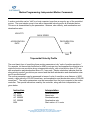
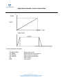
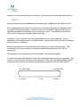
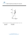
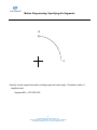
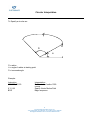
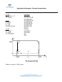
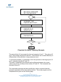
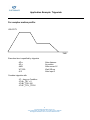
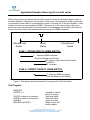
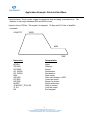
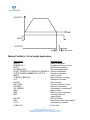
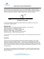
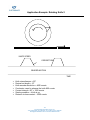
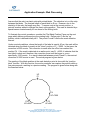
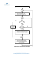
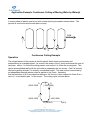
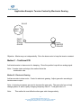
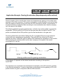
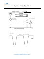
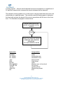
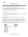
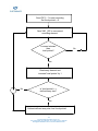
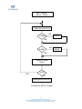
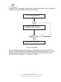
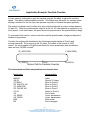
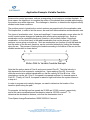
Application Example: Bouncing off of a limit switch When using a pulse type switch with the HM command, the motor will always begin motion in the same direction, irrespective of the position of the motor. One method for using a pulse type or momentary home switch is to implement a routine to "bounce off" of the limit switches. In this method, the motor is commanded to HOME. If the motor is on the 'wrong' side of the home switch, the motor will eventually hit the limit switch. If this happens, the controller will move the motor to the other side of the home switch and re-issue the HOME command. Reverse Limit Switch Home Switch Forward Limit Switch CASE 1: WRONG SIDE OF HOME SWITCH: 1. Execute HOME command (Hits the Reverse Limit Switch) 2. Move to other side of home switch (XRDIST) 3. Re-home CASE 2: CORRECT SIDE OF HOME SWITCH: 1. Execute HOME command (Hits the Reverse Limit Switch) Figure 1. This figures shows the method of bouncing off of the limit switch. The Program: #BOUNCE HSTATE = 0 XFDIST=<value to be inserted> XRDIST=<value to be inserted> #HOMEX HMX;BGX;HSTATE=1 ;Variable to identify status of homing ;See Note below. ;See Note below. ;Home X routine ;Begin motion, set status variable 78 ELECTROMATE INDUSTRIAL SALES LTD. TOLL FREE PHONE (877) SERVO98 • TOLL FREE FAX (877) SERVO99 [email protected] • WWW.ELECTROMATE.COM AMX;HSTATE=0 EN #LIMSWI JP#FWDX,(_LFX=0)&(HSTATE=1) JP#REVX,(_LRX=0)&(HSTATE=1) MG "HIT LIMIT SWITCH" AB0 #FWDX AMX PRX=XFDIST BGX AMX HMX BGX RE1 #REVX AMX PRX=XRDIST BGX AMX HMX BGX RE1 ;After motion complete, clear status variable ;End of homing routine ;Limit switch subroutine ;Bounce off forward limit switch if homing ;Bounce off reverse limit switch if homing ;Otherwise, return a message ; and abort motion ;Forward Bounce Routine ;Wait for motion to stop after hitting limit ;Move off of limit to other side of home ;Begin motion ;Wait for motion to complete ;Re-home X axis ;Begin motion on X axis ;Return from routine & re-enable trippoint ;Reverse Bounce Routine ;Wait for motion to stop after hitting limit ;Move off of limit to other side of home ;Begin motion ;Wait for motion to complete ;Re-home X axis ;Begin motion on X axis ;Return from routine & re-enable trippoint Notes: This program includes two routines for bouncing off of both limit switches. Once the system is configured the homing routine will only require one 'bounce' routine (#FWDX or #REVX). This program can be reduced once the required routine has been identified. The values for XFDIST and XRDIST must be opposite polarity For example, XFDIST might be - 3000 CTS, and XRDIST might be 10000 CTS. 79 ELECTROMATE INDUSTRIAL SALES LTD. TOLL FREE PHONE (877) SERVO98 • TOLL FREE FAX (877) SERVO99 [email protected] • WWW.ELECTROMATE.COM Application Example: Making Jumps Out of Automatic Subroutines The automatic subroutines, LIMSWI, POSERR and ININT must be properly terminated to be reenabled. LIMSWI and POSERR must be ended with the command RE or a ZA command must be given. The subroutine #ININT must be ended with the command RI. RE and RI are used to end the subroutine just as EN is used to end other subroutines. To make and unconditional jump from #ININT, there are two methods for re-enabling the interrupt capability; 1)Re-issue the command II. 2) Use a ‘null’ routine. This routine allows for the execution of the RI command before the unconditional jump. #ININT Example: #TEST II1 #LOOP1 MG”WAITING FOR INTERRUPT” WT1000 JP#LOOP1 EN #DONE MG”DONE WITH INTERRUPT” JP#LOOP1 EN #ININT MG”INTERRUPT ON INPUT” #WAIT JP#WAIT,@IN[1]=0 JS#RESETI ZS JP#DONE EN #RESETI RI1 Test routine Set Input Interrupt on input 2 Simple loop function Message Wait 1000msec Jump to subroutine End program Routine to execute when interrupt cleared Message Jump to subroutine End Input Interrupt routine Display message Wait for input to be cleared Conditional jump statement Call’null’ subroutine Zero stack Jump to #DONE routine End of ININT subroutine Null routine ININT ending command (re-enables #ININT) 80 ELECTROMATE INDUSTRIAL SALES LTD. TOLL FREE PHONE (877) SERVO98 • TOLL FREE FAX (877) SERVO99 [email protected] • WWW.ELECTROMATE.COM Application Example: Stop at a Mechanical Limit • Drive the motor at initial speed of 10000 ct/s, with acceleration and deceleration set at 100000 ct/s2 • Expect a mechanical stop after 20,000 counts. • Slow down to a speed of 2000 ct/s before the mechanical stop. • Start deceleration at 20000 –480=19,520. • Detect the mechanical stop by observing the following error. • When stop is detected apply a constant force corresponding to 2 volts motor command. (Amplifier is in current mode). • Stop the motion of motor. Program Interpretation #STOP AC 100000 DC 100000 JG 10000 BGX AD 19520 JG 2000 #L JP#L,_TEX<100 TL 2 STX EN Label Acceleration Deceleration Speed Start motion Wait for point Deceleration Check for error Limit output Stop Motion End 81 ELECTROMATE INDUSTRIAL SALES LTD. TOLL FREE PHONE (877) SERVO98 • TOLL FREE FAX (877) SERVO99 [email protected] • WWW.ELECTROMATE.COM Application Example: Pause Motion Task: When input is triggered, decelerate vector motion to a stop, when input is de-activated, resume motion • Create #ININT subroutine in Program • Use General Use Input to generate interrupt • Set Vector Speed, VS, to zero • Pause while interrupt remains active Instruction Interpretation II1 #LOOP VP –4000,0 CR 1500,270,-180 VP 0,3000 CR 1500,90,-180 VE BGS AMS JP#LOOP EN #ININT N=_VS VS 0 #PAUSE JP#PAUSE, @IN[1]=0 VSN RI1 Set X axis only for vector motion Label program Define vector move Define arc segment Define vector move Define arc segment Vector end Begin sequence After move sequence Repeat motion when done End program Input Interrupt routine Save Current Vector Speed Set Speed to 0 Wait while input is active Conditional jump Resume Retune from interrupt 82 ELECTROMATE INDUSTRIAL SALES LTD. TOLL FREE PHONE (877) SERVO98 • TOLL FREE FAX (877) SERVO99 [email protected] • WWW.ELECTROMATE.COM Application Example: Motion Complete Timeout This simple program will issue the message “X fell short” if the X axis does not reach the commanded position within 1 second of the end of the profiled move. Instruction Interpretation #BEGIN TW 1000 PA 10000 BGX MCX EN #MCTIME MG “X fell short” EN Begin main program Set the time out to 1000ms Position Absolute command Begin motion Motion Complete trip point End main program Motion Complete Subroutine Send out a message End subroutine without restoring trippoint 83 ELECTROMATE INDUSTRIAL SALES LTD. TOLL FREE PHONE (877) SERVO98 • TOLL FREE FAX (877) SERVO99 [email protected] • WWW.ELECTROMATE.COM Application Example: Correcting Wrong Operator Input Data Instruction Interpretation #BEGIN IN “ENTER SPEED”, SPEED JG SPEED;BGX; JP #BEGIN EN #CMDERR JP#DONE,_ED<>2 JP#DONE,_TC<>6 MG “SPEED TOO HIGH” MG “TRY AGAIN” Begin main program Prompt for speed Begin motion Repeat End main program Command error utility Check if error on line 2 Check if out of range Send message Send message ZS1 JP #BEGIN #DONE ZS0 EN1 Adjust stack Return to main program End program if other error Zero stack End program and restore trippoint The above program prompts the operator to enter a jog speed. If the operator enters a number out of range (greater than 8 million), the #CMDERR routine will be executed prompting the operator to enter a new number. 84 ELECTROMATE INDUSTRIAL SALES LTD. TOLL FREE PHONE (877) SERVO98 • TOLL FREE FAX (877) SERVO99 [email protected] • WWW.ELECTROMATE.COM DMC-2000 Application Example: Using the Term-H/P Pendant Here is an example that uses the hand held terminal to monitor when a key is being held down. In this example, the function keys F1 - F4 are being used to increase and decrease the X and Y jog speed. As the key is held down, the jog speed (s) is continuously changed until the key is released. The F5 key is used to stop the motion on both the X and Y axes. The terminal has to be set up for fast repeat function which causes the terminal to send out characters every 50msec. When holding down a key, the first character is not repeated until after approximately 2 seconds, so there is a special case for when the key is first held down. When the key is held down, the communication interrupt jumps to the Increase, Decrease, or STOP routine. In the each routine, the controller clears the communication buffer (P2CH), sets a new speed if F1, F2, F3 or F4 was depressed and waits for 50msec. If the communication interrupt does not take control within the 50msec, then the key must have been released and the next command causes the system to stop (ST command). The terminal was configured with the Key Click Disabled to avoid the sound generated when holding the key down. #F4TEST FIRST=1 CC 9600,0,0,0 MG {P2},{^27},"V" SPEEDX=10000 SPEEDY=10000 JG SPEEDX,SPEEDY BGXY CI 2 #LOOP WT 1000 MG "PRESS F4 TO HOLD, THEN STOP" JP#LOOP EN #COMINT ZS JP#STOP1,(P2CH=F4) & (FIRST=1) JP#STOP,(P2CH=F4) 85 ELECTROMATE INDUSTRIAL SALES LTD. TOLL FREE PHONE (877) SERVO98 • TOLL FREE FAX (877) SERVO99 [email protected] • WWW.ELECTROMATE.COM JP#LOOP EN #STOP1 FIRST=0 CI -1 CI 2 WT2000 ST EN #STOP CI -1 CI 2 WT100 ST EN 86 ELECTROMATE INDUSTRIAL SALES LTD. TOLL FREE PHONE (877) SERVO98 • TOLL FREE FAX (877) SERVO99 [email protected] • WWW.ELECTROMATE.COM Application Example: Point-to-Point Move • Requirements: Drive a motor toward a mechanical stop and apply a constant force. The distance to the stop is between 8000 and 8500 counts. • Apply a force of 20 lbs. This equals, for example, 1.6 Amp and 0.8 Volts of amplifier command. VELOCITY 20000 5000 TIME Instruction Interpretation #PUSH PR 9000 SP 20000 AC 100000 DC 100000 BGX AD 6000 SP 5000 AD 8000 #LOOP JP #LOOP,_TEX<100 TL 0.8 EN Label Distance Speed Acceleration Deceleration Start motion Wait until distance = 6000 Lower the speed Ready for contact Define subroutine Wait for contact Limit the output End program 87 ELECTROMATE INDUSTRIAL SALES LTD. TOLL FREE PHONE (877) SERVO98 • TOLL FREE FAX (877) SERVO99 [email protected] • WWW.ELECTROMATE.COM Application Example: Pick and Place Pick and Place An automated IC insertion machine is used to pick up a part at an X,Y location and move it to the proper location on the circuit board. A PC-based controller needs to move an XY table along a straight line to the specified locations. The pick-up head is controlled by the Z axis which raises the head during movement and lowers the head during placement. Requirements System resolution: 0.1 micron Accuracy: 1micron Speed: 40,000 counts/sec PC-based Operation The motion requirement is to pick up a part at coordinate X1, Y1 and to place it at coordinate X2, Y2. Once the coordinates are specified, the controller drives the XY table on a straight line to the pick-up location. Once there, the pick-up head, which is controlled by the Z axis, is lowered and the holding solenoid is activated. Next, the pick-up head is raised, the table is driven to the new location, and the pick-up head is lowered. Finally, the solenoid is released and the pick-up head is raised again. The motion program includes two parts. The first, #INITIAL, is performed once to initialize the system. Consecutive moves are executed with the program #PICK. Specifically, the controller computes the differences, DX, DY, between the starting position, X0, Y0, and the pick-up position, X1, Y1. It then commands the XY axes to move on a straight line with the VP DX, XY instruction. Upon completion, the Z axis is lowered and then the output bit 1, which activates the solenoid, is energized. The process is repeated to move the motor to the new coordinate. The instructions are given in the following program. Instruction Interpretation #INITIAL HMXY BGXY AMXY X0=0 Y0=0 #PICK DX=X1-X0 DY=Y1-Y0 VP DX,DY Label Drive X and Y to home Start motion Wait until completion Define starting position as zero Define starting position as zero Label Find X difference Find Y difference Command motion 88 ELECTROMATE INDUSTRIAL SALES LTD. TOLL FREE PHONE (877) SERVO98 • TOLL FREE FAX (877) SERVO99 [email protected] • WWW.ELECTROMATE.COM VS 40000 VA 200000 VD 200000 VE BGS AMS PR,,-50000 SP,,20000 AC,,80000 DC,,80000 BGZ AMZ SB 1 WT 20 PR,,50000 BGZ DX=X2-X1 DY=Y2-Y1 VP DX,DY VE AMZ BGS AMS PR,,-50000 BGZ AMZ CB 1 WT 20 PR,,50000 BGZ X0=X2 Y0=Y2 EN Vector speed Vector acceleration Vector deceleration End of move Start XY motion Wait for motion completion Move head down (Z-axis) Z speed Z acceleration Z deceleration Start Z motion Wait for Z motion completion Set output bit -- solenoid Wait 20 ms Raise head Start Z motion Compute the X difference Compute the Y difference Motion command End of move Wait for Z completion Start XY motion Wait for XY completion Lower head Start head motion Wait for Z motion completion Clear output bit -- release solenoid Wait 20 ms Raise head Start Z motion Update starting X position Update starting Y position End program 89 ELECTROMATE INDUSTRIAL SALES LTD. TOLL FREE PHONE (877) SERVO98 • TOLL FREE FAX (877) SERVO99 [email protected] • WWW.ELECTROMATE.COM Application Example: Press Fitting Machine A linear slide moves a machined component under an automated tool that inserts a bearing into the part. The objective is to ensure the insertion force falls within a specified range. The actual force required will be recorded for each insertion with an analog strain gage. If the force required falls outside the range, the assembly must be rejected. A PC will be used as the operator station using Visual Basic for the operator interface. Requirements Force range: 1.00-25.50 lbs (programmable limits) Accuracy: ±0.0002 inch Resolution of motion: 40000 counts per inch (zero backlash ball nut on ball screw) Solution An advanced level controller is used to control the motion of the system. One axis is used to position the linear slide under the tool holding the bearing while the second axis controls the vertical position of the insertion press. Force measurements are made from a strain gage that outputs an analog voltage. This voltage will be read by one of the analog inputs of the controller and used to monitor the insertion pressure. If the force exceeds the upper limit at any time during the insertion, the motion will be aborted and the parts rejected. Likewise, if the insertion depth is reached and the force remains below the minimum value the parts must be rejected. Visual Basic is used to produce a user interface that displays the motion of the system and system status, as well as position and insertion pressure values. This program communicates to the controller through the VBX custom control produced by Galil Motion Control. A description of portions of the Visual Basic code follows: When a form is first loaded, the code within the FORM_LOAD procedure is automatically executed. In this case communication is established and then the commands to be sent to the card during each polling interval are defined. Finally, the polling interval is set and the polling is enabled. Sub Form_Load () ‘sets up the communication dmcshell1.dmcaddress = “1000” dmcshell1.dmcconnect = True ‘allows polling of the card for the position and pressure values dmcshell1.dmcinterrogate(0) = “TPX” dmcshell1.dmcinterrogate(1) = “TPY” dmcshell1.dmcinterrogate(2) = “MG @AN[1]” ‘sets the time between polls and begins polling dmcshell1.dmcpollinterval = 200 90 ELECTROMATE INDUSTRIAL SALES LTD. TOLL FREE PHONE (877) SERVO98 • TOLL FREE FAX (877) SERVO99 [email protected] • WWW.ELECTROMATE.COM dmcshell1.pollcontroller = True End sub Three status variables are polled every 200 milliseconds: X position, Y position, and the value of analog input #1. Each response is placed into the correct panel by the following code. Sub DMCShell1_DMCInterrogate (index As Integer, response As String) ‘routine is run each time a poll is completed If index = 0 Then press_pos_panel.caption = Val(response) End if If index = 1 Then slide_pos_panel.caption = Val(response) End if If index = 2 Then pressure_panel.caption = Val(response) End if End sub If the button labeled “START” is pressed commands must be sent to download a DMC program and then execute it within the control card: Sub start_button_Click () ‘routine downloads the DMC file “press.dmc” to controller then executes it dmcshell1.filename = “press.dmc” dmcshell1.dmcfileoperation = 1 dmcshell1.dmccommand = “XQ” End sub 91 ELECTROMATE INDUSTRIAL SALES LTD. TOLL FREE PHONE (877) SERVO98 • TOLL FREE FAX (877) SERVO99 [email protected] • WWW.ELECTROMATE.COM Application Example: Autostart Cut to Length Cut to Length A plastic strip is pulled from a feedroll and must be cut at a specified length. Also, the number of pieces must be programmable. The operation is done by advancing the web to a specified distance and activating the cutter. The operation must be stand-alone. The operator has a hand-held terminal for selection the length and number of cuts. Requirements Range of cut: 6” to 36” System resolution: 0.0002” or 5000 counts per inch Slew speed: 12 inches/sec Acceleration/deceleration: 200 in/s2 Cutting time interval: 200 ms Required accuracy: ±0.001” Stand-alone Operation An advanced level stand-alone controller prompts the operator to enter the length in inches, L, and the number of cuts, N. To start the operation, a switch connected to input 1 is turned on. The cutting cycle includes the motion interval followed by the cutting interval. The actual cutting tool is controlled by toggling output 2 on the controller. The operation ends when the number of cuts is completed or when input 1 is turned off, whichever occurs first. As the operation is stand-alone with a single axis of motion, the DMC-2010 controller and TermH-P2 hand-held pendant were selected. The control program below is downloaded to the controller via the RS232 or RS422 port and stored in non-volatile memory permitting standalone operation. 92 ELECTROMATE INDUSTRIAL SALES LTD. TOLL FREE PHONE (877) SERVO98 • TOLL FREE FAX (877) SERVO99 [email protected] • WWW.ELECTROMATE.COM VELOCITY TIME 5V INPUT 1 0V OUTPUT 2 200 msec Motion Profile for Cut to Length Application: Instruction #AUTO CC9600,0,0,1 DPO,0 KI1;KD64;KP10 IN {P2} “ENTER CUT LENGTH IN INCHES”,L IN {P2} “ENTER NUMBER OF CUTS”,N #WAIT JP #WAIT, @IN[1]=0 C=0 #LOOP PR L*5000 SP 60000 AC 1000000 BGX AMX SB2 WT 200 CB2 C=C+1 JP #E,C=N Interpretation Label for autostart Configure for Term-H input Define home position Set tuning parameters Prompt for operator Prompt for operator Label for wait Wait until input 1 is high Initialize cut counter Label for loop Convert inches to counts Speed in counts/sec 2 Acceleration in counts/sec Begin motion Wait for motion complete Activate cutter, set output 2 high Wait 200 msec Deactivate cutter, clear output 2 Increment cut counter Exit if done 93 ELECTROMATE INDUSTRIAL SALES LTD. TOLL FREE PHONE (877) SERVO98 • TOLL FREE FAX (877) SERVO99 [email protected] • WWW.ELECTROMATE.COM JP #LOOP,@IN[1]=1 #E EN Repeat if input 1 is still high Exit End program 94 ELECTROMATE INDUSTRIAL SALES LTD. TOLL FREE PHONE (877) SERVO98 • TOLL FREE FAX (877) SERVO99 [email protected] • WWW.ELECTROMATE.COM Application Example: Position Follower I Objective: The motor must follow an analog signal. When the analog signal varies by 10V, motor must move 10000 counts. Approach 1 - Point-to-Point Method: Read the analog input and command X to move to that point. Instruction Interpretation #POINTS SP 7000 AC 80000 DC 80000 #LOOP VP=@AN[1]*1000 Label Speed Acceleration Deceleration Label branch program Read analog input, compute position Command position Start motion After completion Repeat End PA VP BGX AMX JP #LOOP EN 95 ELECTROMATE INDUSTRIAL SALES LTD. TOLL FREE PHONE (877) SERVO98 • TOLL FREE FAX (877) SERVO99 [email protected] • WWW.ELECTROMATE.COM Application Example: Position Follower II Objective: The motor X follows the motor Y at a ratio of one-to-one. Approach Method: Force the follower to run at a speed that is proportional to the following error. Instruction #FOLLOW DP_TPY AC 100000 DC 100000 JGO BGX #LOOP E=_TPY-_TPX JG E*20 JP #LOOP EN Interpretation Label Set initial positions Acceleration Deceleration Set in jog mode Start motion Following error Update speed Repeat End 96 ELECTROMATE INDUSTRIAL SALES LTD. TOLL FREE PHONE (877) SERVO98 • TOLL FREE FAX (877) SERVO99 [email protected] • WWW.ELECTROMATE.COM Application Example: Modified Position Follower III Method: Modify the program to eliminate steady state following errors. Instruction Interpretation #FOLLOW2 DP_TPY P=20 I=2 VI=0 AC 100000 DC 100000 JG0 BGX #LOOP E=_TPY-_TPX VI=E*I+VI S=E*P+VI JGS JP#LOOP EN Label Set initial conditions Proportional constant Integral constant Initial value of integrator Acceleration Deceleration Set X in jog mode Start motion Define subroutine Following error Integral term Total speed Update speed Repeat End 97 ELECTROMATE INDUSTRIAL SALES LTD. TOLL FREE PHONE (877) SERVO98 • TOLL FREE FAX (877) SERVO99 [email protected] • WWW.ELECTROMATE.COM Application Example: Continuous Move Method: Read the analog input, compute the commanded position and the position error. Command the motor to run at a speed in proportion to the position error. Instruction Interpretation #CONT AC 80000 DC 80000 JG 0 BGX #LOOP VP=@AN[1]*1000 VE=VP-_TPX VEL=VE*20 JG VEL JP #LOOP EN Label Acceleration rate Deceleration rate Start jog mode Start motion Define subroutine Compute desired position Find position error Compute velocity Change velocity Change velocity End 98 ELECTROMATE INDUSTRIAL SALES LTD. TOLL FREE PHONE (877) SERVO98 • TOLL FREE FAX (877) SERVO99 [email protected] • WWW.ELECTROMATE.COM DMC-1200 DMC-1800 DMC-1600 DMC-2000 DMC-1700 Application Example: Generating a Helical Motion Profile Background: It is possible to create a helical motion profile using any 3 (or more) axis controller. This is accomplished by commanding a coordinated circular move between 2 axes and gearing a third axis to the vector motion of the coordinated axes. Program Example: This example shows how to implement helical motion: #HELIX REM VARIABLES USED: REM PITCH ENCODER CTS TRAVERSED/CIRCLE VECTOR SPEED OF CIRCLE GEAR RATIO SWEPT ANGLE OF CIRCLE ANGLE>32000 FOR LARGE REM SPEED REM RATIO REM ANGLE REM LOOPCNT USED IF TRAVERSES REM LASTLOOP ANGLE FOR LAST LOOP #SETUP PITCH= 360 RADIUS= 5000 SPEED= 50000 VS SPEED RATIO= PITCH/(2*3.14159*RADIUS) GA,,S Specify Vector Speed as Master for Z axis GR,,RATIO IN "ENTER THE TRAVERSE DISTANCE (ENCODER CTS):",DIST ANGLE=360 * DIST/PITCH LOOPCNT=@INT[ANGLE/32000] LASTLOOP= 0 JP#MOVE,ANGLE<32000 LASTLOOP=ANGLE - (LOOPCNT*32000) ANGLE=32000 #MOVE CNT=0 99 ELECTROMATE INDUSTRIAL SALES LTD. TOLL FREE PHONE (877) SERVO98 • TOLL FREE FAX (877) SERVO99 [email protected] • WWW.ELECTROMATE.COM #LOOP VMXY CR RADIUS,0,ANGLE VE BGS AMS CNT=CNT+1 JP#LOOP,CNT<LOOPCNT ANGLE=LASTLOOP JP#LOOP,(CNT<(LOOPCNT+1)) & (LASTLOOP > 0) EN In the above example, a circle is created using the X and Y axes of the controller. The Z axis is geared to the coordinated motion of the X and Y axes to create the helix. The gear RATIO is determined by the PITCH of the helix and the circumference of the circle. One unavoidable limitation of the circle (CR) command is that the maximum swept ANGLE of a circle must be less than 32,000 degrees. As a result, the program executes multiple passes of #LOOP for any calculated angle greater than 32,000 degrees. Method to Increase Accuracy of Helical Motion For the highest possible accuracy, it is recommended that the gear ratio be calculated using the formula ratio=pitch/(2*pi*radius) on a standard calculator. The resolution of the controller is limited to approximately four decimal places so the ratio you enter should be the gear ratio you calculate truncated to four decimal places. You will now need to calculate the amount of error you accumulate during the helical motion due to rounding so that the #CORRECT routine can compensate for it. First, you need to determine the value of the gear ratio as internally represented by the controller. The controller stores decimal values as fractions with a resolution of 1/65,536. To determine the internal value of the gear ratio, multiply the entered gear ratio by 65,536, truncate any fractional part of the result, and divide by 65,536. You can also determine this directly by typing in a gear ratio (ex. GR ,,.0114) and then multiplying the _GRn operand by 10,000 and displaying the result (ex. MG _GRZ*10000). This result divided by 10,000 should give you the same result as the calculation method. Next, determine the amount of error that results from the rounding of the gear ratio. To do this, you must calculate the distance which the geared axis will travel and compare it to the distance you specified using DIST. The actual distance traveled is equal to the internal ratio divided by the exact value of the ratio you calculated times DIST. Round this number to the nearest integer. Subtract this value from DIST and enter as DELTA. There is one more parameter to calculate: INTERVAL. INTERVAL is the number of counts it takes for the geared axis to 100 ELECTROMATE INDUSTRIAL SALES LTD. TOLL FREE PHONE (877) SERVO98 • TOLL FREE FAX (877) SERVO99 [email protected] • WWW.ELECTROMATE.COM accumulate one count of error. It is equal to the actual distance calculated above divided by DELTA. This value should be rounded down to the nearest integer. Example: The following example shows the calculations performed for the sample program above: PITCH=360 RADIUS=5000 DIST=3999 ANGLE = EXACT RATIO = 360*DIST/PITCH = 3999 PITCH/(2*PI*RADIUS) = 0.011459155 \ Calculated value 0.0114 \Value entered in program RATIO*65536 = 747.1104 \ Truncate decimal part and divide by 65536 RATIO = INTERNAL RATIO: 747/65536 = 0.011398315 ACTUAL DISTANCE = INTERNAL RATIO/EXACT RATIO * DIST = 0.011398315/0.011459155 * 3999 = 3977.768 \round to nearest integer = 3978 DELTA = DIST-ACTUAL DISTANCE = 3999-3978 = 21 INTERVAL = ACTUAL DISTANCE/DELTA = 3978/21 = 189.4286 \ round down = 189 101 ELECTROMATE INDUSTRIAL SALES LTD. TOLL FREE PHONE (877) SERVO98 • TOLL FREE FAX (877) SERVO99 [email protected] • WWW.ELECTROMATE.COM Application Example: Helical Motion Example: Perform a helical move with 20 turns with 1000 count radius, and a vertical length of 2000 counts. Note that the total length in the XY plane is 20 • 2πR=125,664 The Z move is 2000 Therefore, the gear ratio is 0.0159 Instruction Interpretation VM XY CR 1000,0,7200 VE VS 5000 VA 10000 VD 10000 GAS GR,,0.0159 BGS EN Specify vector plane Define arc segment Vector End Vector speed Vector acceleration Vector deceleration Define vector motion as master Define 2 axis gear ratio Begin sequence End program 102 ELECTROMATE INDUSTRIAL SALES LTD. TOLL FREE PHONE (877) SERVO98 • TOLL FREE FAX (877) SERVO99 [email protected] • WWW.ELECTROMATE.COM Motion Programming: Electronic Gearing • Allows 1 to 8 axes per controller to be electronically geared to master encoder • Eliminates mechanical gears • User specifies: GA n where n=X for main encoder as master n=CX for command position as master n=S for vector motion as master GR Gear Ratio(±127.9999 range) • Can change Gear Ratio during motion • Example: Instruction Interpretation GA Y GR 5,,-2.5 PR,1000 SP,100000 AC,250000 DC,250000 BG Y Y is master X ratio = 5, Z ratio = -2.5 Master position Master speed Master acceleration Master deceleration Begin Motion 103 ELECTROMATE INDUSTRIAL SALES LTD. TOLL FREE PHONE (877) SERVO98 • TOLL FREE FAX (877) SERVO99 [email protected] • WWW.ELECTROMATE.COM Application Example: Rotating Knife A rotating knife system, illustrated below, is used to cut webs of paper or plastics at a given length. The web moves independently and the knife is synchronized so that the blade moves at the same linear speed as the web during the cutting interval. When the cutting is completed, the knife is advanced or retarded in a manner that produces a required cut length. KNIFE WEB Rotating Knife System The method illustrated here applies with slight modifications to applications of printing on moving webs or applying labels. Requirements Web speed: Zero to 120 inches per second, independent Knife circumference: (π x diameter) = 20 inch Required cut length: 16 to 40 inches, programmable Resolution of web encoder: 1000 counts/inch Resolution of knife: 10000 counts/rev or 500 counts/inch Required accuracy: 0.005 inch noncumulative error motion (master) The knife is driven by a motor and an external amplifier. An encoder senses the position of the moving web. Operation The knife motion is synchronized with the web motion by electronic gearing. This, by itself, produces a cut length of exactly 20 inches. To achieve other cut lengths, the knife must be advanced or retracted an additional distance. This is achieved by generating some secondary motion on top of the electronic gearing. For example, to achieve a cut length of 16 inches, the knife is advanced a distance of 4 inches with a programmable speed and acceleration, on top of the geared motion. The cutting cycle is performed by the following program. It assumes that the operation starts with the web at rest and the knife at the “up” position. Further, it is assumed that the cutting interval is ±45° wide. 104 ELECTROMATE INDUSTRIAL SALES LTD. TOLL FREE PHONE (877) SERVO98 • TOLL FREE FAX (877) SERVO99 [email protected] • WWW.ELECTROMATE.COM The correction motion is generated after the completion of the cutting cycle. The speed of the correction, S, equals 90% of the web speed in order to ensure that even under negative corrections, the knife never moves backward. The acceleration rate of the correction, A, is proportional to the square of the web speed to create an effect of cam-like motion. In the given system, the web encoder is connected to the Y axis and the knife is controlled by the X axis. The process continues as long as the input I1 is high. When I1 is turned off, the knife gearing is terminated and the knife is decelerated to a gradual stop at the up position. Instruction Interpretation #KNIFE L=23 DP 0 GAY GR 0.5 POINT = 6250 C = (20-L)*500 MF POINT V = _TVY/200 PRC SP V*90 AC V*V*2.5 DC V*V*2.5 BGX AMX POINT = POINT + 10000 JP #LOOP, @IN[1]=1 PR 3750 AC 60000000 DC 600000 SP _TVY/2 BGX GR0 EN Required cut length in inches Starting knife position = 0 Set Y as master Electronic gearing ratio Point to start correction Correction move in counts Wait for correction point Read web speed Correction distance Correction speed Correction acceleration Correction deceleration Start correction Wait for completion of correction Update next correction point Repeat if I1 = 1 Stopping distance Acceleration to stop mode Stopping deceleration Transition speed Start transition Stop gearing End program 105 ELECTROMATE INDUSTRIAL SALES LTD. TOLL FREE PHONE (877) SERVO98 • TOLL FREE FAX (877) SERVO99 [email protected] • WWW.ELECTROMATE.COM Application Example: Rotating Knife 2 KNIFE SPEED CORRECTION GEARED MOTION TIME • • • • • • • Knife circumference = 20" Desired cut length = 16" Knife encoder resolution = 4000 counts Conclusion, need to advance the knife 800 counts Contact interval = 90º = 1000 counts Starting condition -- Knife is up Distance to clear contact -- 2500 counts 106 ELECTROMATE INDUSTRIAL SALES LTD. TOLL FREE PHONE (877) SERVO98 • TOLL FREE FAX (877) SERVO99 [email protected] • WWW.ELECTROMATE.COM Instruction Interpretation DP 0 GAY GR 1 V=2500 #WAIT JP #WAIT,_TPX<V #MOVE PR 800 SP 20000 BGX AMX V=V+4000 JP #WAIT EN Define X position as zero Set paper (Y) as master Set gear ratio 1:1 Define variable Define subroutine Wait to clear contact Move correction distance Define distance Define speed Begin motion After motion of X axis Update contact end point Repeat cycle End program 107 ELECTROMATE INDUSTRIAL SALES LTD. TOLL FREE PHONE (877) SERVO98 • TOLL FREE FAX (877) SERVO99 [email protected] • WWW.ELECTROMATE.COM Application Example: Web Tension Control Web processing applications often require tension control. In the most demanding case, the web is pulled by an independent process, which may be continuous or start/stop. The tension is sensed by a load cell and the requirement is to supply the web from a feed roll under constant tension. FEED ROLL X LOAD CELL The same process applies to winding the web on a take-up roll under constant or variable tension. Requirements Speed of master: 0-20 inches/sec, start/stop Master encoder resolution: 400 counts/in Feed roll diameter: 3.5 - 16 inches Feed roll encoder resolution: 10,000 counts/rev Load sensor output: 0-10V for 0-20 oz Tension accuracy: ±0.5 oz Operation The length of the web pulled by the master process is monitored by an encoder with a resolution of 400 counts/in. The feed roll is driven by a motor with a tachometer and an encoder of 10,000 counts/rev. The motor is driven by an external amplifier. The amplifier is configured in the velocity mode (closing inner velocity tach loop) for added stability in view of the heavy inertial load. The feed roll motion is divided into two parts: coarse and fine motion. The coarse motion is achieved by gearing the feed roll to the master process and continuously estimating the gear 108 ELECTROMATE INDUSTRIAL SALES LTD. TOLL FREE PHONE (877) SERVO98 • TOLL FREE FAX (877) SERVO99 [email protected] • WWW.ELECTROMATE.COM ratio. Since the ratio is not known precisely, this mode performs most of the required motion but not all of it. The fine motion are correction moves performed on top of the electronic gearing in response to variations in tension. Here the errors in tension are monitored and the motor is driven at a proportional speed on top of the gearing. It is assumed that the initial gear value, G, is known. The initial value can be computed or measured directly. The gear ratio may be continuously estimated by determining the ratio of the frequencies of the two encoders and filtering that ratio. In the following program the feed-roll motor is controlled by the X axis and the master is monitored by the Y axis. The program consists of two parts: #GEAR, which estimates the gear ratio and performs the coarse mode, and #TRIM, which performs the fine move. The two programs are executed simultaneously by multitasking. The load cell signal is applied to the analog input #1, and the required sensor level is 4 V. Accordingly, E, the difference between the sensor output and 4, is the error in tension. The motor is required to jog at a speed that is equal to 20 times E. Instruction Interpretation #INITIAL GAY GRG JG0 BGX XP = _TPX YP = _TPY #GEAR Y = _TPY X = _TPX JP #GEAR, Y = YP DX = X-XP DY = Y-YP XP = X YP = Y RATIO = DX/DY G = (G*7+RATIO)/8 GRG JP#GEAR EN #TRIM E = @AN[1]-4 Label Set Y as master Initial gear ratio Initial jog speed Begin motion Read initial X position Read initial Y position Label subroutine Read new Y Read new X Repeat if no Y motion Compute X increment Compute Y increment Update X position Update Y position Ratio of increments Estimate gear Update gear Repeat cycle End program Label Tension error 109 ELECTROMATE INDUSTRIAL SALES LTD. TOLL FREE PHONE (877) SERVO98 • TOLL FREE FAX (877) SERVO99 [email protected] • WWW.ELECTROMATE.COM JG E*20 JP #TRIM EN Fine jog speed Repeat End program 110 ELECTROMATE INDUSTRIAL SALES LTD. TOLL FREE PHONE (877) SERVO98 • TOLL FREE FAX (877) SERVO99 [email protected] • WWW.ELECTROMATE.COM Application Example: Web Processing Assume that the web is a plastic strip with printed labels. The objective is to cut the strip between the labels. The nominal length of each label is 40 cm. However, due to the elasticity of the web, the length may vary. To ensure cuts at the correct position, a periodic mark as added to indicate the exact cutting position. This mark is detected by a special sensor located exactly 40 cm ahead of the cutting knife. To illustrate the control procedure, consider first The Blade Position Figure on the next page which defines positions along the rotating knife. Define point P1 as the “up” position, which is defined initially as 0. The points P2 and P3 define the mark detection interval. Under nominal conditions, where the length of the label is exactly 40 cm, the mark will be detected when the blade is exactly at the “down” position of P1 + 5000. In that case, the correction is 2000 counts. This correction is made after the motor has reached the position P4. If the mark is detected at an earlier point, say P1 + 4900, it indicates that the next label is short and, therefore, the correction move must be longer or, more specifically, 2100 counts. If no mark is detected between points P2 and P3, the nominal correction of 2000 counts is used. The actual program is given below. The reading of the blade position at the mark detection point is done with the “position latch” function. With this function, the motion controller can capture the position within a few microseconds, resulting in a precise reading. The program is given below along with the flowchart below UP P1 P4 UP+7000 P2 UP+4000 P3 UP+600 111 ELECTROMATE INDUSTRIAL SALES LTD. TOLL FREE PHONE (877) SERVO98 • TOLL FREE FAX (877) SERVO99 [email protected] • WWW.ELECTROMATE.COM Definition of Blade Positions Instruction Interpretation #MARK DP0 UP = 0 GAY GR 0.1 SP 50000 AC 400000 DC 400000 #P2 JP#P2,_TPX<UP+4000 ALX #LATCH JP#NOMARK,_TPX>UP+6000 JP#LATCH,_ALX = 1 E = UP+5000-_RLX JP#P4 #NOMARK E=0 #P4 JP#P4,_TPX<UP+7000 D = 2000+E PR D BGX AMX UP = UP+10000 JP#P2 EN Label Define starting position as 0 Initial value UP position Set Y as master Gear ratio 0.1 Speed of correction Acceleration of correction Deceleration of correction Label subroutine Wait for point P2 Arm position latch Label subroutine If position >P3, skip Wait for latch Second correction,E Jump to subroutine Label subroutine Set E = 0 Label subroutine Wait for Point P4 Compute motion distance Position correction Start Move Wait for end of correction Update position at UP Repeat the process End of program 112 ELECTROMATE INDUSTRIAL SALES LTD. TOLL FREE PHONE (877) SERVO98 • TOLL FREE FAX (877) SERVO99 [email protected] • WWW.ELECTROMATE.COM SET INITIAL VALUES WAIT FOR POINT P2 ARM POSITION LATCH YES POS>P3 NO DISARM LATCH NO LATCHED YES READ LATCHED POSITION COMPUTE CORRECTION E WAIT FOR POSITION P4 MOVE DISTANCE=2000+D UP=UP+10000 Flowchart for Web Processing Example 113 ELECTROMATE INDUSTRIAL SALES LTD. TOLL FREE PHONE (877) SERVO98 • TOLL FREE FAX (877) SERVO99 [email protected] • WWW.ELECTROMATE.COM Application Example: Continuous Cutting of Moving Webs by Waterjet A moving sheet of plastic must be cut with a water jet along the pattern shown below. The process is continuous and the web does not stop. WEB MOTION Y X Continuous Cutting Example Operation The unique feature of this system is that the plastic sheet moves continuously and independently at a variable speed. As a result, the motion of the X motor must equal the sum of two parts: motion 1 to follow the cutting pattern, and motion 2 to follow the moving web. This can be accomplished easily with the controller by separating the two moves. Part 2 is done by electronic gearing and part 1 is done by coordinated motion. The web motion is monitored by an independent encoder whose output is applied to the Z axis. Assuming that the resolution of all 3 encoders are the same, the X motor is then required to follow Z at a ratio of 1 to accomplish part 1 of the motion. The cutting cycle is shown below. D (-3400,7000) C (-3400,1000) E (-1400,7000) F (-1400,1000) B (-2400,0) A(0,0) 114 ELECTROMATE INDUSTRIAL SALES LTD. TOLL FREE PHONE (877) SERVO98 • TOLL FREE FAX (877) SERVO99 [email protected] • WWW.ELECTROMATE.COM Cutting Cycle The motion starts at the point A with the waterjet turned off (output bit 1 = 0). It moves toward point B, where the waterjet is turned on, and continues to C, D, E, F, and back to B which becomes the starting point of the next cycle. In order to keep the waterjet location over the correct position, we must synchronize the cutting speed with the web speed. Note that the length of one cutting cycle, including the path from A to all the points, equals 20,680 counts. At the same time, the web advances 2400 counts. This implies that the vector speed, VS, must be equal to 8.616 times the speed of Y. This method, however, is not precise and will create some errors that can cause position drift of X. To eliminate this possibility, we define the starting point of the first cycle as X = 0. Later, we check the position of X at the start of all following cycles. If the starting position of X is positive, the cutting speed is slow and the speed is increased by a correction factor E. Instruction Interpretation #WTRJET DP0 GAZ GR1 VMXY #LOOP E = _TPX/2400 SPEED = _TVZ*(1+E) VS SPEED*8.616 VP -2400,0 CR 1000,170,-90 VP -3400,7000 CR 1000,180,-180 VP -1400,1000 CR 1000,0,-90 VE BGS AV 2400 SB1 AMS CB1 JP #LOOP EN Label Define starting X position Set Z as master X follows Z at 1:1 Vector mode XY plane Label subroutine Drift correction factor Master speed Command vector speed Motion AB Motion BC Motion CD Motion DE Motion EF Motion F to end End of motion Start move Wait for point B Turn waterjet on Wait for end of cycle Turn waterjet off Repeat the cycle End of program 115 ELECTROMATE INDUSTRIAL SALES LTD. TOLL FREE PHONE (877) SERVO98 • TOLL FREE FAX (877) SERVO99 [email protected] • WWW.ELECTROMATE.COM Application Example: Web Cutting with Fixed Cut Length • To cut at a given length, add PR command on top of gearing. Knife circumference=20” Desired cut length=16” Knife encoder resolution=4000 counts Knife must be advanced 4000/5=800 counts • Position of knife to clear contact: 2500 counts Instruction Interpretation #A DP0,0 GA,X GR,.25 V=2500 #LOOP MF,V PR,800 BGY AMY V=V+4000 JP#LOOP EN Label Define X and Y position 0 Define X axis ask master* Set Slave Gear Ratio 1 Position of Knife to advance Wait for knife to reach pos. Advance knife position Begin advancing movement Wait for move to complete Add 1 Rev to next position Repeat *For DMC-1000, DMC-1500 controllers the gear command should be: GAX 116 ELECTROMATE INDUSTRIAL SALES LTD. TOLL FREE PHONE (877) SERVO98 • TOLL FREE FAX (877) SERVO99 [email protected] • WWW.ELECTROMATE.COM Application Example: Tension Control by Electronic Gearing SLAVE FEED ROLL IDLER WITH STRAIN GAUGE MASTER ROLLER Objective: Master may run independently. Drive the slave motor to keep the tension constant. Method 1 - Traditional PID Add a tachometer to slave motor for damping. Close the position loop with an analog signal. Note: If master starts and stops, this method limits the acceleration rate. Method 2 - Electronic Gearing Add an encoder to slave motor. Control in electronic gearing. Adjust gear ratio according to tension sensor output. Note: As tension increases, we need to increase the gear ratio. The gear ratio has a slowly changing base, B, and a rapidly changing temporary value R. Total gear ratio is G. Note: This method is most effective when gear ratio changes slowly. 117 ELECTROMATE INDUSTRIAL SALES LTD. TOLL FREE PHONE (877) SERVO98 • TOLL FREE FAX (877) SERVO99 [email protected] • WWW.ELECTROMATE.COM Instruction Interpretation #TENSION GAX GR, 0.3 JG,0 BGY XQ#GEAR,1 #LOOP E=@AN[1]-4 JG,E*20 JP#LOOP EN Label Define master Initial gear ratio Set slave in jog mode Start mode Execute gear estimation routine Label Compute tension error Trim the speed Repeat the process End Instruction Interpretation #GEAR G=0.3 XP=_TPX YP=_TPY #LG X=_TPX JP#LG,X=XP Y=_TPY DX=X-XP DY=Y-YP XP=X YP=Y R=DY/DX G=(G*7+R)/8 GRG JP#LG EN Gear program Initial gear value Initial X position Initial Y position Label Read new X position Verify that X motion is non-zero Read Y position Find X increment Find Y increment Update previous X position Update previous Y position Compute ratio Filter ratio and estimate gear Adjust gear ratio Repeat End 118 ELECTROMATE INDUSTRIAL SALES LTD. TOLL FREE PHONE (877) SERVO98 • TOLL FREE FAX (877) SERVO99 [email protected] • WWW.ELECTROMATE.COM Application Example: Gearing Acceleration The following program can be used to slowly engage electronic gearing. This is useful when the master axis is already moving, allowing for a smooth transition on the slave axis. This program users the X axis as a master and the Y axis as a slave for illustration. Line numbers 6, 15, 23, 27, 31 must be modified if gearing is between different axes. Instruction #SMGEAR TTL=10000 CT=TTL GO=10 R=1 RATE=10 GA ,X #LP3 JP#G,((CT=TTL)&(GO=1))|((CT=0)&(GO=-1)) JP#H, ((CT>0)&(GO=1))|((CT,TTL)&(GO=-1)) JP#STOP, GO=0 JP#LP3,GO=99 JP#TOOHI,@ABS[GO}>1 JP#LP3 #STOP GRY=0 CT=TTL JP#LP3 #TOOHI GO=99 JP#LP3 #G;JP#LP3,(RATE<1)|(RATE>10000);AT0 #H;CT=CT+((GO*-1)*RATE) GRY=(1-(CT/TTL))*R;AT-10 JP#LP3,(CT>=0)&(CT<=10000) JP#ZERO,CT<0 CT=10000 GRY=0 JP#LP3 #ZERO CT=0 GRY=R JP#LP3 EN 119 ELECTROMATE INDUSTRIAL SALES LTD. TOLL FREE PHONE (877) SERVO98 • TOLL FREE FAX (877) SERVO99 [email protected] • WWW.ELECTROMATE.COM The user is required to set the following variables: 1. GO is used to engage and disengage the gearing. GO=1 engages gearing GO=-1 disengages gearing GO=0 disengages gearing immediately 2. R is the gear ratio between the master axis and the slave axis. The default value for R is 1. 3. RATE is used to set the amount of time to be used to engage gearing. The time is given by the equation: T=(10000/RATE)*10msec. This variable must be a value between 1 and 10000 and the default value 10 (T=10sec). If the master is moving at a constant rate, the acceleration of the slave axis can be calculated as: (SPEEDmaster*R*RATE)/(10000*.01) per sec2 120 ELECTROMATE INDUSTRIAL SALES LTD. TOLL FREE PHONE (877) SERVO98 • TOLL FREE FAX (877) SERVO99 [email protected] • WWW.ELECTROMATE.COM Application Example: Synchronizing Two Conveyor Belts with Trapezoidal Velocity Correction. Instruction Interpretation GAX GR,2 PR,300 SP,5000 AC,100000 DC,100000 BGY Define master axis as X Set gear ratio 2:1 for Y Specify correction distance Specify correction speed Specify correction acceleration Specify correction deceleration Start correction 121 ELECTROMATE INDUSTRIAL SALES LTD. TOLL FREE PHONE (877) SERVO98 • TOLL FREE FAX (877) SERVO99 [email protected] • WWW.ELECTROMATE.COM DMC-1200 DMC-1800 DMC-1600 DMC-2000 DMC-1700 Application Example: Gearing Acceleration (Superimposed profile method) Normal operation of the controller has a slave axis instantaneously gearing to the master upon execution of the GRn command. This can be undesirable in certain situations, such as the case when the master is already moving at the time the GRn command is issued. In this situation, it may be beneficial to engage the slave according to some acceleration rate, therefore ramping up to the speed of the master. The following application program superimposes, or blends, two motion profiles to provide this acceleration. The first profile is a PR move on the slave axis with a known AC and DC. This profile is combined with the GRn profile to give the final acceleration to the gear ratio. The theory behind this is as follows. Setting the AC of a negative PR move to the maximum number will cause instantaneous acceleration. The profile will then follow the DC rate to complete the move. When this profile is added to the instantaneous acceleration of the positive GRn command, the resultant profile has the slave ‘ramping’ to the speed of the master according the DC rate set. GR 1 + PR -Q AC=¥ = Resulting Profile SP=GR*SP master Velocity profiles used for gearing acceleration In this diagram, Q depends on the desired acceleration according to the equation, 2 Q=SP /2DC This opposite move counteracts the instantaneous acceleration of the GR command, resulting in the smooth acceleration. In order to ramp down, or decelerate from the gearing, a PR in the positive direction is given in conjunction with the GR0 command. 122 ELECTROMATE INDUSTRIAL SALES LTD. TOLL FREE PHONE (877) SERVO98 • TOLL FREE FAX (877) SERVO99 [email protected] • WWW.ELECTROMATE.COM The limitation to this method is a slight jump in the motion as the gearing is engaged. This is due to the controller attempting to command the servo at the maximum acceleration. The magnitude of this jump is influenced by the speed of the master. #GEARAMP START=0;STOP=0 AC67107840 GAY IN"SPEED OF THE MASTER (cts/sec)?",JOG IN"FINAL GEAR RATIO?",RATIO IN"TIME TO ACCELERATE (ms)?",RATE RATE=RATE/1000 SPEED=(JOG*RATIO) DECEL=SPEED/RATE DC DECEL;SP SPEED RAMP=(SPEED*SPEED)/(2*_DCX) JG,JOG;BGY MG"TYPE START=1 TO ENGAGE" MG"OR TYPE STOP=1 TO ABORT" #LOOP;JP#LOOP,(START=0)&(STOP=0) JP#STOP,STOP=1 PR-RAMP;BGX;GR RATIO #VELOOP;JP#VELOOP,(SPEED=>_TVX)&(STOP=0) JP#STOP,STOP=1 MG"TYPE START=0 TO DISENGAGE" MG"OR TYPE STOP=1 TO ABORT" #LOOP2;JP#LOOP2,(START=1)&(STOP=0) JP#STOP,STOP=1 GR0;PRRAMP;BGX #VELOOP2;JP#VELOOP2,(_TVX>0)&(STOP=0) JP#STOP,STOP=1 WT1000 STY JP#GEARAMP #STOP AB1 JP#GEARAMP EN 123 ELECTROMATE INDUSTRIAL SALES LTD. TOLL FREE PHONE (877) SERVO98 • TOLL FREE FAX (877) SERVO99 [email protected] • WWW.ELECTROMATE.COM Application Example: Wire Cutter An operator activates a start switch. This causes a motor to advance the wire a distance of 10”. When the motion stops, the controller generates an output signal which activates the cutter. Allowing 100 ms for the cutting completes the cycle. Suppose that the motor drives the wire by a roller with a 2” diameter. Also assume that the encoder resolution is 1000 lines per revolution. Since the circumference of the roller equals 2π inches, and it corresponds to 4000 quadrature, one inch of travel equals: 4000/2π=637 count/inch This implies that a distance of 10 inches equals 6370 counts, and a slew speed of 5 inches per second, for example, equals 3185 count/sec. The input signal may be applied to input 1, for example, and the output signal is chosen as output 1. The program starts at a state that we define as #A. Here the controller waits for the input pulse on I1. As soon as the pulse is given, the controller starts the forward motion. Upon completion of the forward move, the controller outputs a pulse for 20 ms and then waits an additional 80 ms before returning to #A for a new cycle. Instruction Interpretation #A AI1 PR 6370 SP 3185 BGX AMX SB 1 WT 20 CB1 WT 80 JP #A Label Wait for input 1 Distance Speed Start Motion After motion is complete Set output bit 1 Wait 20 ms Clear output bit 1 Wait 80 ms Repeat the process 124 ELECTROMATE INDUSTRIAL SALES LTD. TOLL FREE PHONE (877) SERVO98 • TOLL FREE FAX (877) SERVO99 [email protected] • WWW.ELECTROMATE.COM DMC-1200 DMC-1800 DMC-1600 DMC-2000 DMC-1700 Application Example: Variable Length Ecam Motion Set up the ECAM function so that X is the master and Y is the follower. The ECAM profile will be set up to move the Y axis at the beginning of the ECAM cycle. Then the Y axis will wait for the X axis to 'roll over' and the cycle will start again. To cut different lengths, all we do is stop the ECAM cycle, change the length of the X axis rollover, then engage the ECAM mode again. Here is an example of that program: Assumptions: 1) X length is 600 counts or greater 2) 4000 encoder counts per Y revolution #INIT EAX EM LENGTH, 4000 EP 100,0 ET[0]=,0 ET[1]=,1000 ET[2]=,2000 ET[3]=,3000 ET[4]=,4000 LOOP=5 #B ET[LOOP]=,4000 LOOP=LOOP+1 JP#B,LOOP<255 EN #START EB1 Execute this code only once at beginning Set X as ECAM master Sets the roll over point of X and Y Set interval for table for 100 master counts Enter ECAM table values. Y will start moving Y stops moving a full revolution later Fill in table with the end position To start ECAM motion Enable ECAM 125 ELECTROMATE INDUSTRIAL SALES LTD. TOLL FREE PHONE (877) SERVO98 • TOLL FREE FAX (877) SERVO99 [email protected] • WWW.ELECTROMATE.COM EG,0 EN Engage ECAM Insert code to change the variable 'LENGTH' #CHANGE MF 3999 EB0 EM To change the cut length After position end of Y axis motion Disable ECAM LENGTH,4000 Set new X rollover value EB1 EG,0 EN Note: X axis can be moving during this entire operation. 126 ELECTROMATE INDUSTRIAL SALES LTD. TOLL FREE PHONE (877) SERVO98 • TOLL FREE FAX (877) SERVO99 [email protected] • WWW.ELECTROMATE.COM Application Example: Cutting Material on Moving Belt • A plastic sheet is placed on a moving belt. • The belt is driven open loop. • The objective is to perform a circular cut on the sheet. • Method: - Attach an encoder to the belt. Input to AUX X. - Belt encoder is master. - Y axis is geared to belt. - XY axes perform circular move. #MOVE VMXY GAY=DX GRY=1 GMY=1 CR 5000,0,360 VS 7000 VA 100000 VD 100000 VE BGS EN Label program Specify vector motion path Define master encoder gear axis Define y axis gearing Set gantry mode Perform circle Define vector speed Define vector acceleration Define vector deceleration Vector end Begin sequence End program 127 ELECTROMATE INDUSTRIAL SALES LTD. TOLL FREE PHONE (877) SERVO98 • TOLL FREE FAX (877) SERVO99 [email protected] • WWW.ELECTROMATE.COM Application Example: Flying Shears PLASTIC SHEETS SHEAR + E + MASTER ENCODER SLAVE MOTOR M E AMP MOTION CONTROLLER VELOCITY SYNC TRANSITION TIME 128 ELECTROMATE INDUSTRIAL SALES LTD. TOLL FREE PHONE (877) SERVO98 • TOLL FREE FAX (877) SERVO99 [email protected] • WWW.ELECTROMATE.COM Flying Shears Example: Need to cut material in 12-inch intervals (60,000 counts per cycle). Flying shears must move forward 8 inches and return back rapidly. Motion starts at X = 0 Turn cutter on at X = 5000 Turn cutter off at X = 35000 Start motion back at X = 40000 Instruction Interpretation #SHEARS DP0 GAY GR1 #WAIT1 JP #WAIT1,_TPX<5000 SB1 #WAIT2 JP #WAIT2,_TPX<35000 CB1 #WAIT3 JP #WAIT3,_TPX<40000 PR -60000 AC 1000000 DC 1000000 SP_TVY*4 BGX AMX JP #WAIT1 Label program Define position zero Select Y as master Shears is slave Wait subroutine Shears between 0 - 5000 Turn cutter on Wait subroutine Shears between 5000 and 35000 Turn cutter off Wait subroutine Wait for end point Return move Define acceleration Define deceleration Speed proportional to master Begin X motion After move of X motion Repeat process 129 ELECTROMATE INDUSTRIAL SALES LTD. TOLL FREE PHONE (877) SERVO98 • TOLL FREE FAX (877) SERVO99 [email protected] • WWW.ELECTROMATE.COM Motion Programming: Tangent Motion When two motors perform coordinated motion in a plane, it is often desirable to control a third motor in a manner whereupon its angle remains tangent to the direction of motion. This feature is useful in applications such as cutting cardboard with a knife. As the knife moves in the plane, it is necessary to keep the blade angle tangent to the motion trajectory. The user must specify several parameters to generate the tangent motion. First, the user must select the motors for the different roles. For the rest of this discussion, assume that X and Y generate the motion in the plane and Z is the tangent motor. The second parameter is the resolution of the Z motor (or the number of units of resolution that will turn the Z motor 1°). For example, if the encoder resolution is 3600 counts per revolution, this parameter is 10. Finally, the position of the Z motor at which its angle is 0° in the XY plane must be given. These parameters define the requirements for the tangent motion completely. To generate tangent motion by a controller, first select the axes with the instruction VM. For example, the instruction: VM XYZ selects the first two axes, X and Y, to form the motion in the plane, and the third axis, Z, to form the tangent motion. The remaining two parameters are defined with the instruction TN m,n. For example, the instruction TN 20,700 sets the resolution to 20 counts per degree. This also indicates that when the Z motor is at the absolute position of 700 counts, its angle in the XY plane is 0°. 130 ELECTROMATE INDUSTRIAL SALES LTD. TOLL FREE PHONE (877) SERVO98 • TOLL FREE FAX (877) SERVO99 [email protected] • WWW.ELECTROMATE.COM Motion Programming: Proportional Motion Another useful feature of motion controllers is their ability to generate additional controlled motion in proportion to the vector speed. This feature is useful with the generation of helical motion whereby two axes form circular motion and a third axis moves at a proportional velocity in the vertical direction. Proportional velocity is also useful in applications such as dispensing glue. Suppose that the motion in the XY plane is performed at variable speed; in order to produce uniform amounts of glue per unit of length, it is necessary to drive the glue pump at a rate that is proportional to the vector speed in the XY plane. Electronic gearing can be used to implement proportional motion is done by Electronic Gearing (See previous examples). Once the motion in the plane is defined, that motion is defined as the master motion and a third motor is required to follow it at a specific gear ratio. The procedure is illustrated by the following example. Consider an XYZ system where the resolution is 100 counts/mm for all axes. The objective is to generate a helical motion with 10 full turns of 5 mm radius in the XY plane and a height of 20 mm in the Z direction. The vector speed in the XY plane is 20 mm/s, and both the vector acceleration and deceleration equal 1000 mm/s2. The motion parameters can be expressed in units of resolution by the parameters radius = 5 mm = 500 counts vector speed = 20 mm/s = 2000 counts/s 2 5 2 accel/decel = 1000 mm/s = 10 counts/s To determine the gear ratio, note that the path in the XY plane consists of 10 circles with a radius of 5 mm resulting in a total length of 314 mm. On the other hand, the motion in the Z direction is 20 mm. The ratio between the two motions is ratio = 20/314 = 0.0637 which suggests a gear ratio of 0.0637 The required motion is generated by the following program. Instruction Interpretation #HELICAL VMXY GAS GR,,0.0637 CR 500,0,3600 Label Define XY plane Select master motion Set Z as follower Define 10 circles 131 ELECTROMATE INDUSTRIAL SALES LTD. TOLL FREE PHONE (877) SERVO98 • TOLL FREE FAX (877) SERVO99 [email protected] • WWW.ELECTROMATE.COM VE VS 2000 VA 100000 VD 100000 BGS EN End of path Vector speed Vector acceleration Vector deceleration Start motion End of program These data points are sent to the motion controller that interpolates between them before performing the motion. The following discussion presents another application of the contouring mode. 132 ELECTROMATE INDUSTRIAL SALES LTD. TOLL FREE PHONE (877) SERVO98 • TOLL FREE FAX (877) SERVO99 [email protected] • WWW.ELECTROMATE.COM Application Example: Constant Force • Drive a motor against a load. Measure the force with an analog transducer. The objective is to maintain a constant force. • Method 1: Modify the controller to accept analog feedback (standard option). Suppose we need a force of 4 Volts With 12 bit ADC 10 Volts = 2048 counts 4 Volts = 819 counts PA 819 BGX Begin Motion • Method 2: With standard controller, close the loop with incremental rotary encoder. Jog the motor continuously to hold the force constant. Make the jog speed proportional to the force error. Instruction Interpretation #FORCE JG 0 BGX #LOOP E = 4 - @AN[1] V = E*1000 JGV JP #LOOP EN Label program Set controller to jog mode Begin motion Label subroutine Compute proportional force error Define jog speed Jog motor Repeat process End program • With multitasking, this program can be run in the background. • Constant Force Example 2: Drive the X motor against a slowly moving target and maintain a constant force between the two elements. The contact force is measured by a load cell whose output is applied 133 ELECTROMATE INDUSTRIAL SALES LTD. TOLL FREE PHONE (877) SERVO98 • TOLL FREE FAX (877) SERVO99 [email protected] • WWW.ELECTROMATE.COM to analog input #1. Assume that the desired force level corresponds to a signal level of 5V and that forward motion increases the tension between the two elements. The simplest control procedure is to run the motor in the jog mode where the motor runs continuously at a specified speed. The controller reads the analog signal to determine the force level and sets the speed of the motor in proportions with the error in the force level. The flowchart and program is shown below. DRIVE X MOTOR IN JOG MODE WITH ZERO INITIAL SPEED LOOP READ THE ANALOG SIGNAL COMPUTE THE TENSION ERROR,ER SET NEW SPEED=100*ER Instruction Interpretation #FORCE AC 100000 DC 100000 JG 0 BGX #LOOP ER=5-@AN[1] VEL=ER*100 JG VEL JP#LOOP EN Label Acceleration rate Deceleration rate Set jog mode Start motion Label Measure error in force level Set velocity Update velocity Repeat the process End 134 ELECTROMATE INDUSTRIAL SALES LTD. TOLL FREE PHONE (877) SERVO98 • TOLL FREE FAX (877) SERVO99 [email protected] • WWW.ELECTROMATE.COM Application Example: Joystick Control Read the voltage of an X-Y joystick and drive the motors at proportional velocities. 10 Volts = 3000 rpm = 200,000 count/s Speed/Analog Input = 200000/10=20000 Instruction Interpretation #JOYS JG 0,0 BG XY #LOOP VX=@AN[1]*20000 VY=@AN[2]*20000 JG VX, VY JP #LOOP EN Label Set in Jog Mode Start motion Define subroutine Read joystick and compute speed X Read joystick and compute speed Y Change speeds Jump to subroutine End program 135 ELECTROMATE INDUSTRIAL SALES LTD. TOLL FREE PHONE (877) SERVO98 • TOLL FREE FAX (877) SERVO99 [email protected] • WWW.ELECTROMATE.COM Application Example: Joystick with Nonlinear Function Instruction Interpretation #NLNR JG 0 BGX #L A=@AN[1] V=A*A*A+A*1000 JGV JP#L EN Label program Set in Jog Mode Begin motion Define subroutine Read joystick Create nonlinear speed Update speed Jump to subroutine End program 136 ELECTROMATE INDUSTRIAL SALES LTD. TOLL FREE PHONE (877) SERVO98 • TOLL FREE FAX (877) SERVO99 [email protected] • WWW.ELECTROMATE.COM Application Example: Single Axis Joystick Routine with Deadband Task : Read the voltage of a single axis joystick and drive the motors at proportional velocity. Also, do not affect motor speed if analog input is less than .5 volts (tolerance for offset when joystick is in center position). INSTRUCTION INTERPRETATION #JOYSTK JG0 BGX #LOOP V1=@AN[1] JP#GO,.5<@ABS[V1] V1=0 #GO JGX=V1*1000 JP#LOOP EN Label ‘Joystick’ Set Jog mode with Jog Speed 0 Begin motion on X axis Label ‘Loop’ Let V1 = value of analog input 1 Update speed if input is > .5 volts Otherwise, set jog speed to 0 Label Change jog speed Repeat End program 137 ELECTROMATE INDUSTRIAL SALES LTD. TOLL FREE PHONE (877) SERVO98 • TOLL FREE FAX (877) SERVO99 [email protected] • WWW.ELECTROMATE.COM Application Example: Backlash Compensation • An XY table is driven by two servo motors via leadscrews. The coupling has backlash. The system has two linear encoders and two rotary encoders. • Effective where the objective is to move to a final point and stop precisely. Step 1 is to drive the motor with rotary encoders. After the move is complete, read the linear encoder and perform a correction. • Example: Assume the resolution is 1 micron for both rotary and linear encoders. The objective is to move to the absolute position X=3000 Y=4000 Instruction Interpretation #DUAL PA 3000,4000 BGXY AMXY WT20 DX=3000 -_DEX DY=4000 -_DEY PR DX, DY BGXY EN Label program Command motion Wait for completion After X & Y motion Wait for settling Compute X correction Compute Y correction Perform correction Begin motion End program 138 ELECTROMATE INDUSTRIAL SALES LTD. TOLL FREE PHONE (877) SERVO98 • TOLL FREE FAX (877) SERVO99 [email protected] • WWW.ELECTROMATE.COM Application Example: Teach Mode Objective: Record the position of a motor over 4 seconds in 16 ms intervals, and play back. Method: Step 1 - Record positions and store in array Step 2 - Run in Contour Mode from array Instruction Interpretation #RECORD RA POS[251] RD_TPX RC 4,251 EN #RUN CMX DT4 C=0 #LRUN D=C+1 DX=POS[D]-POS[C] CD DX WC C=C+1 JP #LRUN,C<250 DT0 CD0 EN Label program Select the arrays Select data Record 251 times at 16=24 ms intervals End program To run the motor Contour Mode Time interval Initialize counter Label subroutine Define variable Compute increment Contour data Wait for completion Increment counter Repeat 250 times Stop Contour Mode Contour data End program 139 ELECTROMATE INDUSTRIAL SALES LTD. TOLL FREE PHONE (877) SERVO98 • TOLL FREE FAX (877) SERVO99 [email protected] • WWW.ELECTROMATE.COM Program Flow: Multitasking • Eight independent programs called "threads" can run simultaneously • All threads have equal priority • One thread can execute or halt another thread • All trippoints in every thread available • Main thread only uses INPUT command, IN. Input interrupts main thread only • Useful for background PLC functions; truly independent motions • Example: Commands: XQ #Label,n Execute Program Thread, where n=0 through 3 is thread number. 0 is main thread. Hxn Halt Execution of Thread 140 ELECTROMATE INDUSTRIAL SALES LTD. TOLL FREE PHONE (877) SERVO98 • TOLL FREE FAX (877) SERVO99 [email protected] • WWW.ELECTROMATE.COM Application Example: Multitasking Complex applications often require several independent tasks to be executed at the same time. The controller allows simultaneous execution of up to four independent applications programs. This is an ideal feature for executing independent operations of PLC tasks in the background. Each separate task is defined as task 0 through 3. Any task can be executed or halted from another task. For example, XQ#POS1,0 begins Task 0. HX0 halts Task 0. All controller commands, including event triggers and conditionals, can be used in each task. However, input interrupts and input prompts are available only in Task 0. Multitasking--Example 1: Background PLC. Functions Example: This example shows how four independent programs can be executed simultaneously from the controller memory. The main task #MAIN starts all the other tasks--#PLC1, #PLC2, #MOVE-after Input 1 is high. It halts all tasks when Input 1 goes low. #PLC1 sets Output 2 only when Input 2 and Input 3 are high. #PLC2 generates a waveform on Output 1 which is high for 10 msec and low for 40 msec. #MOVE moves the X axis 100 counts, repetitively. The program is illustrated on the following page: Instruction #MAIN AI1 XQ#PLC1,1 XQ#PLC2,2 XQ#MOVE,3 AI-1 HX EN #PLC1 OB2,@IN[2]&@IN[3] JP#PLC1 #PLC2 AT0 #LOOP SB1;AT10 CB1;AT-50 JP#LOOP #MOVE PR100;BGX;AMX WT20;JP#MOVE Interpretation Main Program -- Task 0 After Input 1 high Execute Task 1 Execute Task 2 Execute Task 3 After Input 1 low Halt all tasks End program #PLC1 -- Task 1 Set Output 2 if Input 2 and 3 high Loop #PLC2 -- Task 2 Set reference time Loop label Set Output 1; wait 10 msec Clear Output 1; at 50 msec; reset timer Loop #MOVE -- Task 3 Move 100 counts Wait 20 msec and repeat 141 ELECTROMATE INDUSTRIAL SALES LTD. TOLL FREE PHONE (877) SERVO98 • TOLL FREE FAX (877) SERVO99 [email protected] • WWW.ELECTROMATE.COM Multitasking -- Example 2: Instruction Interpretation #X PR 1000;BGX;AMX PR -1000;BGX;AMX JP #X #Y PR,500;BGY;AMY PR,-500;BGY;AMY JP #Y #TIME AT50;SB1;AT10;CB1 JP #TIME #MAIN JP #EXIT,@IN[1]=1 JP #MAIN #EXIT; HX EN X-Thread Move 1000 Move -1000 Repeat Motion Y-Thread Move 500 Move -500 Repeat Motion I/O Thread Every 50 msec Set Bit 1 Repeat Main Thread If input 1 high, exit Loop if input 1 low Halt all threads End Program • To execute: XQ #MAIN,0 XQ #X,1 XQ #Y,2 XQ #TIME,3 142 ELECTROMATE INDUSTRIAL SALES LTD. TOLL FREE PHONE (877) SERVO98 • TOLL FREE FAX (877) SERVO99 [email protected] • WWW.ELECTROMATE.COM Application Example: Using Multitasking To Produce a Waveform on Output 1 Independent of a Move Instruction Interpretation #TASK1 AT0 CB1 #LOOP AT 10 SB 1 AT -40 Task1 label Initialize reference time Clear Output 1 Loop1 label Wait 10 msec from reference time Set Output 1 Wait 40 msec from reference time, then initialize reference Clear Output 1 Repeat Loop1 Task2 label Execute Task1 Loop2 label Define relative distance Begin motion After motion done Wait 10 msec Repeat motion unless Input 2 is low Halt all tasks CB 1 JP #LOOP1 #TASK2 XQ #TASK1,1 #LOOP2 PR 1000 BGX AMX WT 10 JP #LOOP2,@IN[2]=1 HX The program above is executed with the instruction XQ #TASK2,0 which designates TASK2 as the main thread (i.e. Thread 0). #TASK1 is executed within TASK2. 143 ELECTROMATE INDUSTRIAL SALES LTD. TOLL FREE PHONE (877) SERVO98 • TOLL FREE FAX (877) SERVO99 [email protected] • WWW.ELECTROMATE.COM Application Example: Arrays Arrays are structured memories where data can be stored and retrieved in a certain order. They are useful for storing sequences of position points or output signals. An array is characterized by a name and a size. Each element in the array is identified by its index. For example, the array XPOS may have a size of 100 units. As a consequence, each point is identified as XPOS [N] where N varies between 0 and 99. To store data in the array, we use an instruction such as: XPOS [5] = _TPX which reads the current position of the X axis and stores the value in the array. The value of the position may be later retrieved with instructions of the form: X = XPOS [5] which transfers the position value to the variable X. The use of arrays is illustrated by the following example. The controller is required to move the X & Y axes of a positioning table to four positions characterized by their coordinates. The values of the required points are stored in the arrays XPOS and YPOS. Once the controller reaches the specified point, it must wait a certain amount of time before resuming the motion. The waiting time in milliseconds is stored in the array WAIT. The program is described in two parts. The first part, #STORE, defines the arrays. The second part, RUN, performs the moves according to the requirements. Instruction Interpretation #STORE DM XPOS [4], YPOS [4], WAIT [4] XPOS [0] = 100 XPOS [1] = 320 XPOS [2] = 450 XPOS [3] = 500 YPOS [0] = -100 YPOS [1] = 20 YPOS [2] = 153 YPOS [3] = 200 WAIT [0] = 50 Label Define arrays Set values 144 ELECTROMATE INDUSTRIAL SALES LTD. TOLL FREE PHONE (877) SERVO98 • TOLL FREE FAX (877) SERVO99 [email protected] • WWW.ELECTROMATE.COM WAIT [1] = 100 WAIT [2] = 60 WAIT [3] = 120 EN End program Instruction Interpretation #RUN AC 200000,200000 DC 200000,200000 SP 50000,50000 N=0 #LOOP PA XPOS [N], YPOS [N] BGXY AMXY WT WAIT [N] N = N+1 JP#LOOP, N<4 EN Label Accelerations Decelerations Speeds Initial count Label subroutine Specify final position Start motion Wait for completion Wait specified time interval Increment index Repeat 4 times End program 145 ELECTROMATE INDUSTRIAL SALES LTD. TOLL FREE PHONE (877) SERVO98 • TOLL FREE FAX (877) SERVO99 [email protected] • WWW.ELECTROMATE.COM SET X-Y SPEED, ACCEL AND DECEL N=0 LOOP READ XPOS[N], YPOS[N] COMMAND X-Y MOTION WAIT FOR END OF MOTION WAIT FOR REQUIRED TIME N=N+1 YES N<4 NO END Flowchart for Array Program One of the main uses of the array is for recording motion as described in the following pages. 146 ELECTROMATE INDUSTRIAL SALES LTD. TOLL FREE PHONE (877) SERVO98 • TOLL FREE FAX (877) SERVO99 [email protected] • WWW.ELECTROMATE.COM DMC-1200 DMC-1800 DMC-1600 DMC-2000 DMC-1700 Motion Programming: Infinite Array Recording The following note explains the ability to collect an infinite amount of data. Using the Record Array mode, data is captured and stored in the array space within the controller. The number of data points available is limited to 8000 for the OPTIMA Series controller; with the infinite record feature, the array space is limited only by the size of the hard drive on a host computer. To accomplish this, data is captured and written to the first array element, then the second, and third, and so on. When the end of the array is reached the controller will start at the first element of the array and overwrite the data contained there. This 'loop' will continue until a command is given to stop the Record Array function. The host computer must read the array elements before they are overwritten. This is done using the _RD command. _RD returns the current array element that was just written to by the Record Array function. By reading the array elements as fast as they are being recorded the system can record as much data as can fit in the hard drive. Here is a flow chart for the operation of the host computer program to read the captured data: (See Diagram on next page) 147 ELECTROMATE INDUSTRIAL SALES LTD. TOLL FREE PHONE (877) SERVO98 • TOLL FREE FAX (877) SERVO99 [email protected] • WWW.ELECTROMATE.COM Send 'RC 3,-1' to start recording Set 'local pointer' = 0 Send 'MG _RD' to see current recording element. is current element than local pointer? Yes Read array element and increase 'local pointer' by 1 No Is 'local pointer' = > defined array size? Yes Subtract defined array size from 'local pointer' 148 ELECTROMATE INDUSTRIAL SALES LTD. TOLL FREE PHONE (877) SERVO98 • TOLL FREE FAX (877) SERVO99 [email protected] • WWW.ELECTROMATE.COM No Here, the host computer reads one element at a time and is always looking at the state of the controller. If the array size is large and the capture rate slow, the host computer could look at the controller less often and upload more than one array element. Please note the command 'RC 3,-1' starts the recording from the host. An example of the commands needed to set up infinite recording is below. These commands set up the Record Array function to capture the X axis position and store it in an array of 1000 elements: DM POSX[1000] define array RA POSX[] specify which arrays to record RD _TPX specify data to be recorded ' TPX' The host computer program starts the recording with the 'RC' command. To stop recording send the command: 'RC 0' 149 ELECTROMATE INDUSTRIAL SALES LTD. TOLL FREE PHONE (877) SERVO98 • TOLL FREE FAX (877) SERVO99 [email protected] • WWW.ELECTROMATE.COM Application Example: Array Data Storage This example makes a coordinated linear move in the XY plane. The Arrays VX and VY are used to store 750 incremental distances which are filled by the program #LOAD. Instruction Interpretation #LOAD DM VX [750],VY[750] CONT=0 N=0 #LOOP VX [COUNT]=N VY [COUNT]=N N=N+10 COUNT=COUNT+1 JP #LOOP,COUNT<750 #A LM XY CONT=0 #LOOP2;JP#LOOP2,_LM=0 JS#C,COUNT=500 Load Program Define Array Initialize Counter Initialize position increment Loop Fill Array VX Fill Array VY Increment position Increment counter Loop if array not full Label Specify linear mode for XY Initialize array counter If sequence buffer full, wait th Begin motion on 500 segment Specify linear segment Increment array counter Repeat until array done End linear Move After Move sequence done Send Message End program Begin Motion Subroutine LI VX[COUNT],VY[COUNT] COUNT=COUNT+1 JP#LOOP2,COUNT<750 LE AMS MG”DONE” EN #C;BGS;EN 150 ELECTROMATE INDUSTRIAL SALES LTD. TOLL FREE PHONE (877) SERVO98 • TOLL FREE FAX (877) SERVO99 [email protected] • WWW.ELECTROMATE.COM Application Example: A Method To Increase Array Space For Use With Record Array When using the record array function, it may be desirable to increase the total number of recorded data points in the controller’s memory. The following method takes advantage of the fact that, often times, the recorded data elements are smaller than the array elements. In this case, the recorded data can be packed. To illustrate, consider a system with one motor which has a complete travel of+/-30000 counts. If the motor position is to be recorded (_TPX), each data point will only require 16 bits of information (16 bits can represent the numbers up to +/-32767). Since each array element on the Galil controllers is 48 bits – each array element can hold 3 data elements. An Example: To further illustrate, the following program commands the X axis to move in a sinusoidal motion over a #RECORD DP 0 DA *[] DM CB UFF[1002], FINBUFF[6000] COUNT=0 CBUFF #CLRC CBUFF[COUNT]=0 COUNT=COUNT+1 JP#CLRC, COUNT<1002 COUNT=0 FINBUFF #CLRA FINBUFF[COUNT]=0 COUNT=COUNT+1 JP#CLRA,COUNT<6000 RTIM=2 VMXN VS 1000 CR 8000,0,36000 Record Function Define Position De-allocate all arrays and variables CBUFF record array, FINBUFFfinal array Routine to clear Routine to clear Set Record Update Time to 2msec Set up sine motion on X axis (demo) Set up record function on CBUFF 151 ELECTROMATE INDUSTRIAL SALES LTD. TOLL FREE PHONE (877) SERVO98 • TOLL FREE FAX (877) SERVO99 [email protected] • WWW.ELECTROMATE.COM RA CBUFF[] Record position Information Reset counter to zero Reset array index to zero Begin circular array recording (1002 pts) Begin Motion Sequence RD_TPX COUNT=0 INDEX=0 RC RTIM,-1002 BGS Define temporary variable, TEMP TEMP=0 HIGH=0 PTR=0 #LOOP PTR=_RD WT 10 JP #ROLL, PTR<HIGH HIGH=PTR JP#LOOP,(PTR<(30+INDEX)) #UPDATE TEMP=CBUFF[INDEX] JS#SIGN, TEMP<0 TEMP=(TEMP&32767) FINBUFF[COUNT]=65536*TEMP INDEX=INDEX+1 TEMP=CBUFF[INDEX] JS#SIGN,TEMP<0 Define temporary variable, HIGH Define temporary variable, PTR Main Loop Set PTR to last recorded array element Wait 10 msec Jump to ROLL if record array ‘rolled over’ If not, set HIGH to last element recorded Loop until 30 points have been recorded Otherwise, update the final array Pack first element into top of FINBUFF Update index Set highest bit to 1 if negative TEMP=(TEMP&32767) FINBUFF[COUNT]=FINBUFF[COUNT]+TEMP Pack 2nd element into top of FINBUFF INDEX=INDEX+1 Update index TEMP=CBUFF[INDEX] 152 ELECTROMATE INDUSTRIAL SALES LTD. TOLL FREE PHONE (877) SERVO98 • TOLL FREE FAX (877) SERVO99 [email protected] • WWW.ELECTROMATE.COM JS#SIGN,TEMP<0 TEMP=(TEMP&32767) FINBUFF[COUNT]=FINBUFF[COUNT]+(TEMP/65536) rd Pack 3 element into top of FINBUFF INDEX=INDEX+1 COUNT=COUNT+1 JP#REPLAY,COUNT>=6000 #CHECK JP#UPDATE,(INDEX<(PTR-3)) JP#LOOP #ROLL TEMP=CBUFF[INDEX] JS#SIGN,TEMP<0 TEMP=(TEMP&32767) FINBUFF[COUNT]=65536*TEMP INDEX=INDEX+1 TEMP=CBUFF[INDEX] JS#SIGN,TEMP<0 TEMP=(TEMP&32767) FINBUFF[COUNT]=FINBUFF[COUNT]+TEMP INDEX=INDEX+1 TEMP=CBUFF[INDEX] JS#SIGN,TEMP<0 TEMP=(TEMP&32767) FINBUFF[COUNT]=FINBUFF[COUNT]+(TEMP/65536) INDEX=INDEX+1 COUNT=COUNT+1 JPREPLAY,COUNT>=6000 JPROLL,INDEX<1002 INDEX=0 HIGH=0 JP#UPDATE #REPLAY Playback routine STX AMX 153 ELECTROMATE INDUSTRIAL SALES LTD. TOLL FREE PHONE (877) SERVO98 • TOLL FREE FAX (877) SERVO99 [email protected] • WWW.ELECTROMATE.COM Application Example: Recording Controllers can record motion data at a fixed rate and store the data in an array. This data can be later used to duplicate the motion or to analyze it. The recording process includes several steps: First the array where the data is stored must be specified, and later the type of data, such as position, position error, etc., must be defined before the actual recording is accomplished at a specified rate. The process is illustrated by the following example. Write a program that records the position error of the Y axis every 16 msec, a total of 100 times, and stores the results in the array YERROR. The actual recording is done with the instruction RC that has two parameters: the first parameter, n, defines the recording time interval as 2n msec. In the given example, n = 4 results in 16 msec intervals. the second parameter sets the number of the recorded points. Instruction Interpretation #RECORD RA YERROR [100] RD _TEY RC 4,100 EN Label Storage array Data type Actual recording End program The following example illustrates how recorded data can be used for analysis. Use the position error data collected in the previous example to perform a statistical analysis on the position error of Y. Determine the maximum and the minimum values as well as the mean square value. The following program performs the required tasks and stores the results under the variables MAX, MIN, and MEAN. Instruction #STAT N=0 MAX = 0 MIN = 0 SUM = 0 #LOOP E = YERROR [N] JP#MAX, E<MAX MAX = E Interpretation Label Initial values Label Read position error Compare with MAX Redefine MAX 154 ELECTROMATE INDUSTRIAL SALES LTD. TOLL FREE PHONE (877) SERVO98 • TOLL FREE FAX (877) SERVO99 [email protected] • WWW.ELECTROMATE.COM #MAX JP#MIN, E>MIN MIN = E #MIN SUM = E*E+SUM N = N+1 JP#LOOP, N<100 MEAN = SUM/100 ROOT = @ SQR[MEAN] EN Label Compare with MIN Redefine MIN Label Compute sum of squares Increment index Repeat 100 times Mean square Root mean square (RMS) End program 155 ELECTROMATE INDUSTRIAL SALES LTD. TOLL FREE PHONE (877) SERVO98 • TOLL FREE FAX (877) SERVO99 [email protected] • WWW.ELECTROMATE.COM N=0 MAX=0 MIN=0 SUM=0 READ DATA POINT E NO E<MAX MAX=E YES NO E>MIN MIN=E YES SUM=E*E+SUM N=N+1 N<100 YES NO RMS=@SQR(SUM/100) Flowchart for #STAT Program 156 ELECTROMATE INDUSTRIAL SALES LTD. TOLL FREE PHONE (877) SERVO98 • TOLL FREE FAX (877) SERVO99 [email protected] • WWW.ELECTROMATE.COM Application Example: Record and Play Back The contour mode is an effective tool for performing record and play-back types of motion. In these applications, the motion is originally generated by manual means. While the motion takes place, the positions of the motors are recorded. Later, the recorded positions are used as the reference positions for repeating the moves. The process in analogous to that of recording music and playing it back. The first part of this process is recording the motion. It requires a controller with the ability to record and store the positions of the motors involved with the motion at the specified times. An advanced level controller, for example, performs the recording automatically at fixed time intervals and stores the data in it’s array. The recorded data can be used as the source for the repeated moves. The contour mode receives position commands from the stored data and performs it as required. To illustrate the process, consider the following example. Record And Playback Example: Consider a robot arm with three degrees of freedom. Each joint can be controlled with an independent motor. The objective is to move the arm manually along a certain trajectory with the motion lasting 12 seconds. The motion is to be repeated later automatically. The first step is to select the time interval as a basis for the recording time. Because the motion is performed manually, it is unlikely to include abrupt changes in velocity. Therefore, we can record the motion at relatively long time intervals of 25 = 32 ms without any loss of information. The number of sampling intervals, which is the ratio between the total motion time and sampling interval, equals N = 12/0.032 = 375 The recording is performed with the following program. It starts by defining the arrays and assigning them for the recorded data. Later, the type of recorded data is noted. In the given example, the positions of the three motors are requested. If we assume that the recording is to start upon a pulse on Input 1, the instruction AI1 delays the start of the recording to the required moment. 157 ELECTROMATE INDUSTRIAL SALES LTD. TOLL FREE PHONE (877) SERVO98 • TOLL FREE FAX (877) SERVO99 [email protected] • WWW.ELECTROMATE.COM Instruction Interpretation #RECORD Label DM XPOS[376], YPOS[376], ZPOS[376] Define arrays RA XPOS[376], YPOS[376], ZPOS[376] Assign arrays for recording RD _TPX, _TPY, _TPZ Define what to record AI1 Wait for start pulse RC 5,376 Start automatic recording EN End of program The motion is generated by the contour mode. Note, however, that the recorded data is expressed in absolute positions whereas the contour mode commands are expressed in position increments. This implies that the position increments must be computed from the absolute positions before the start of the motion. The process is illustrated by the program flowchart on the next page and the program below. Instruction Interpretation #PLAY CMXYZ DT 5 C=0 #LOOP D = C+1 DX = XPOS[D]-XPOS[C] DY = YPOS[D]-YPOS[C] DZ = ZPOS[D]-ZPOS[C] CD DX,DY,DZ WC C = C+1 JP#LOOP, C<375 DT 0; CD0 EN Label Set contour mode Time interval 25 = 32 ms Set index Define subroutine Next index Compute increments Command contour segment End of segment Increment index Repeat if necessary End contour End of program A desirable feature in the playback process is the ability to control the speed. The program shown above repeats the motion at the speed of recording. Speed variations can be performed in different ways; the advanced level controller allows changing the speeds by factors of 2 with the DT instruction. Note the third instruction of the program #PLAY. If that instruction is 158 ELECTROMATE INDUSTRIAL SALES LTD. TOLL FREE PHONE (877) SERVO98 • TOLL FREE FAX (877) SERVO99 [email protected] • WWW.ELECTROMATE.COM changed to DT4, for example, it shortens the contour time interval to 16 ms, resulting in a velocity that is twice as high as the recording velocity. SET CONTOUR MODE C=0 COMPUTE NEXT POINT COMMAND CONTOUR DATA YES C<375 NO STOP CONTOUR MODE Robot Arm Example For finer changes in speed, the user can vary the sample time. The instruction DT5 sets the contour time interval to 32 sampling periods, with a default value of 1 ms each. Changing the sampling interval to 875 µs, for example, shortens the contour time interval to 28 ms, resulting in a 14% increase in speed. 159 ELECTROMATE INDUSTRIAL SALES LTD. TOLL FREE PHONE (877) SERVO98 • TOLL FREE FAX (877) SERVO99 [email protected] • WWW.ELECTROMATE.COM Application Example: Feedrate Override In some cases it is desirable to give the machine operator the ability to adjust the machine speed. This ability is called feedrate override. This feature may be useful, for example, when starting a machine for the first time; the operator may wish to increase the speed gradually. The method of speed control is often done by a potentiometer with an output voltage between 0V and 10V. When the potentiometer output is at the full 10V, the machine is supposed to run at full speed. In all other cases, the speed should be proportional to the potentiometer voltage. To accomplish this function, motion controllers read the potentiometer voltage and adjust the feedrate in proportions. Consider the motion path described by the following example starting at Point A and moving towards B. The motion is in the XY plane, the radius of the corners is 1000 counts, the vector speed is 20,000 counts/s and the vector acceleration and deceleration 2 rates are both 100,000 counts/s . D (-6000,2000) E (-6000,0) C (6000,2000) A(0,0) Motion Path for Feedrate Override The instructions and their interpretations are shown below. Instruction Interpretation #MOVE VM XY VP 6000,0 CR 1000,270,180 VP -6000,2000 CR 1000,90,180 VP 0,0 VE VA 100000 VD 100000 BGS EN Label Specify XY plane Move to Point B Move to Point C Move to Point D Move to Point E Return to Point A End of path Vector acceleration Vector deceleration Start motion End of program 160 ELECTROMATE INDUSTRIAL SALES LTD. TOLL FREE PHONE (877) SERVO98 • TOLL FREE FAX (877) SERVO99 [email protected] • WWW.ELECTROMATE.COM B (6000,0) Repeating the motion of the previous example with feedrate override, the operator generates a voltage in the range between 0V and 10V. This voltage is applied to Analog Input #1 to set a proportional feedrate. The motion is generated by the two programs, #MOVE and #SPEED. Both programs operate simultaneously in multitasking. The program #SPEED reads the analog inputs and adjusts the vector speed continuously. In the second program, #MOVE, the vector speed is not specified. The two programs are listed below. Instruction Interpretation #SPEED A = @AN[1] V = A*2000 VS V JP #SPEED EN Label Read analog voltage Set feedrate Update feedrate Repeat the process 161 ELECTROMATE INDUSTRIAL SALES LTD. TOLL FREE PHONE (877) SERVO98 • TOLL FREE FAX (877) SERVO99 [email protected] • WWW.ELECTROMATE.COM Application Example: Variable Feedrate Some motion control processes, such as an engraving, do not require a constant feedrate. In those cases, the objective is to complete the motion in the shortest time possible while keeping the position error within tolerance. The challenge is, therefore, to determine the highest velocity allowed under those conditions. The position errors in typical motion control systems are proportional to the acceleration rates. This implies that, in order to limit the errors, we must limit the acceleration and deceleration rate. Two types of acceleration exist: linear and centrifugal. Linear acceleration occurs when the XY motion control system changes its feedrate while moving along a straight line. Such an acceleration can be controlled directly and, therefore, can be easily limited. Centrifugal acceleration, on the other hand, is the radial acceleration that occurs when an XY system performs a move along a circular arc. Such an acceleration is a function of both the feedrate and the radius of the arc and, therefore, can be controlled indirectly by limiting the feedrate along the arc. The process of limiting the feedrate according to the radius of the arc and the allowed acceleration is shown below. D D1 C E A B1 B Motion Path for Variable Feedrate Example Note that the motion starts at Point A and moves toward Point B. The initial velocity is high because the first segment is a straight line. Upon reaching Point B1, the motion controller must start a gradual deceleration so that the velocity at Point B is low. After completing a circular arc, Point C, the speed is increased and later it is lowered again at Point D1. Finally, at Point E, the speed is raised to high level before the system comes to a stop at A. In order to program such velocity changes, we need to determine the location of the transition points along the path. For example, let the high and low speeds be 20,000 and 10,000 counts/s, respectively, and let the vector acceleration and deceleration rates be 100,000 counts/s2. To determine the deceleration distance, note that the deceleration time is Time=Speed change/Deceleration=10000/100000=0.1second 162 ELECTROMATE INDUSTRIAL SALES LTD. TOLL FREE PHONE (877) SERVO98 • TOLL FREE FAX (877) SERVO99 [email protected] • WWW.ELECTROMATE.COM Because the average speed on this interval equals 15,000 counts/sec, the deceleration interval is 1500 counts. Accordingly, the coordinates of the points B1 and D1 are (4500,0) and (-4500,2000) respectively. To change the feedrate along the path, we break the segments AB and CD into two parts each and attach a vector speed to each segment by adding the symbol <n at the end of the segment instruction. This sets the attached speed to n counts/s. The resulting program is shown on the following page. Instruction Interpretation #MOVE VMXY VP 4500,0<20000 Label Specify XY plane Move to Point B1 at speed 20000 Move to Point B at speed 10000 Move to Point C - no speed change Move to Point D1 at speed 20000 Move to Point D at speed 10000 Move to Point E Move to Point A at speed 20000 End of path Vector acceleration Vector deceleration Start motion End of program VP 6000,0<10000 CR 1000,270,180 VP -4500, 2000<20000 VP -6000,2000<10000 CR 1000,90,180 VP 0,0<20000 VE VA 100000 VD 100000 BGS EN 163 ELECTROMATE INDUSTRIAL SALES LTD. TOLL FREE PHONE (877) SERVO98 • TOLL FREE FAX (877) SERVO99 [email protected] • WWW.ELECTROMATE.COM DMC-1200 DMC-1800 DMC-1600 DMC-2000 DMC-1700 Application Example: Routine for Monitoring Encoder Failure An encoder failure or a broken encoder wire can cause the motor to run away. There are two main reasons for this: 1. A motor command has been given. In this case, the commanded position changes but the actual position remains constant since the encoder has failed. With a large position error, the controller will supply the motor amplifier with a large command signal. Use of the error limit, the Off-OnError function, and the #POSERR automatic subroutine can be used to limit this problem. 2. The integrator gain term, KI, is non-zero. In this case, a very small position error will cause the controller to produce a motor command that increases to maximum until encoder counts are detected. Since the encoder has failed, the motor commanded will always increase to maximum and cause motor runaway. Use of the Integrator Limit, IL, can limit the maximum amount of signal that will be contributed by the Integrator Gain. (Note that use of IL can also effect the position accuracy during motion). Use of a monitor routine can also detect when an encoder has failed. The following example routine can be executed on an unused thread to monitor the status of the X axis encoder. This routine disables the X axis motor when the controller is producing a command signal above the level required to move the motor and position movement is not detected. The user must determine the minimum signal required to move the motor. #BROKEN OE 1 FRICX=.2 #LOOP AT0 JP#LOOP,(@ABS[_TTX]<FRICX)|(@ABS[_TVX]>0) Encoder failure monitor routine Enable Off-On-Error for X axis FRIC = min torque to move motor Loop until torque above FRIC and motion is not detected. Reset timer during loop AT20 Wait 20 msec JP#KILL,(@ABS[_TTX]>FRICX)&(@ABS[_TVX]=0) If motion still not ELECTROMATE INDUSTRIAL SALES LTD. TOLL FREE PHONE (877) SERVO98 • TOLL FREE FAX (877) SERVO99 [email protected] • WWW.ELECTROMATE.COM detected, kill motor JP#LOOP #KILL AB1 MG "THE X AXIS MOTOR ENCODER HAS FAILED" EN Otherwise, continue looping Kill routine Abort current motion on X Display message 165 ELECTROMATE INDUSTRIAL SALES LTD. TOLL FREE PHONE (877) SERVO98 • TOLL FREE FAX (877) SERVO99 [email protected] • WWW.ELECTROMATE.COM Application Example: Routines for Monitoring Step Motor Operation Galil controllers operate step motors as part of an open-loop system. However, encoder inputs and application memory are provided which allow position maintenance and stall detection for step motors. An encoder is placed on the motor or load and is read using the DE command. The following application program checks for three conditions; the first condition is known as “In Position”. This represents the motor and load reaching the commanded position or within the error band at the end of motion. The second condition is known as “ Position Maintenance”. Here the system is checked to make sure that if the motor is not asked to move, the load is not moving. The third condition is “Stall Detect”. This check makes sure that the system has not stopped in the process of moving to the final destination. Please note that these examples show only X-axis operation, however, they can be expanded to other axes setup for step motor. Monitor Routine #MONITOR DDBNDX=10 PSRX=0 NPSFLG=0 STLFLGX=0 #STPMNT JS #INPSMNT, _BGX=0 JS #STLDTC,_BGX=1 JP#STPMNT Monitor Program Define Deadband variable Define Position Error variable Define In Position flag Define Stall Detect Flag Routine for background execution If not moving, test In Position + Maintenance If moving, test Stall Detect Loop 166 ELECTROMATE INDUSTRIAL SALES LTD. TOLL FREE PHONE (877) SERVO98 • TOLL FREE FAX (877) SERVO99 [email protected] • WWW.ELECTROMATE.COM Position Maintenance #INPSMNT Routine for In Position and Maintenance POSERR=_DEX - _TPX Calculate error between command and encoder JP#ATPOS, @ABS [POSERR]<DDBNDX In Position if error less than Deadband for X NPSFLG=0 Clear In Position Flag when error IP POSERR Increment the position by the amount of error EN End of subroutine In Position #ATPOS NPSFLG=1 EN When In Position, Jump here Set the In Position Flag End of subroutine Stall Detect #STLDTC PSRX=_DEX-_TPX JP#STLX, @ABS[PSRX]>DDBNDX STLFLGX=0 EN #STLX STLFLGX=1 EN Routine for Stall Detect Calculate error from pulses out vs. encoder If error larger than Deadband, jump to Stall Ed of subroutine Jump here when error Stall occurs Set the Stall Detect Flag for X axis End of subroutine 167 ELECTROMATE INDUSTRIAL SALES LTD. TOLL FREE PHONE (877) SERVO98 • TOLL FREE FAX (877) SERVO99 [email protected] • WWW.ELECTROMATE.COM Appendix -- Optima Series DMC-1200, 13x8, 1600, 1700, 1800, 2000, 2100 SERVO MOTOR COMMANDS AF Analog feedback DV Dual loop operation FA Acceleration feedforward FV Velocity feedforward IL Integrator limit KD Derivative constant KI Integrator constant KP Proportional constant NB Notch Bandwidth NF Notch Frequency OF Offset PL Pole SH Servo here TL Torque limit TM Sample time ZR Zero STEPPER MOTOR COMMANDS KS Stepper motor smoothing MT Motor type RP Report commanded position TD Step counts output TP Tell position of encoder DE Define encoder position DP Define reference position BRUSHLESS MOTOR COMMANDS BA Brushless axis BB Brushless phase BC Brushless calibration BD Brushless degrees BI Brushless inputs BM Brushless modulo BO Brushless offset BS Brushless setup BZ Brushless zero I/O COMMANDS AL Arm Latch CB Clear bit CI Communication interrupt CO Configure I/O points EI Enable interrupts II Input interrupt OB Define output bit OC Output compare function OP Output port SB Set bit UI User Interrupts SYSTEM CONFIGURATION AO Analog output (DMC-2100) BN Burn parameters BP Burn program BV Burn variables and arrays CC Configure auxiliary port CE Configure encoder type CN Configure switches CO Configure I/O points CW Data adjustment bit DE Define dual encoder position DP Define position DR DMA/FIFO update rate DV Dual velocity (dual loop) EI Enable interrupts EO Echo off IA Set IP address (DMC-2100) IH Internet handle (DMC-2100) IT Independent smoothing LZ Leading zeros format MO Motor off MT Motor type PF Position format QD QU RS VF Download array Upload array Reset Variable format MATH/SPECIAL FUNCTIONS @SIN[X] Sine of x @COS[X] Cosine of x @COM[X] 1's compliment of x @ASIN[X] Arc sine of x @ACOS[X] Arc cosine of x @ATAN[X] Arc tangent of x @ABS[X] Absolute value of x @FRAC[X] Fraction portion of x @INT[X] Integer portion of x @RND[X] Round of x @SQR[X] Square root of x @IN[X] State of digital input x @OUT[X] State of digital output x @AN[X] Value of analog input x INTERROGATION COMMANDS LA List arrays LL List labels LS List program LV List variables MG Message command QR Data record QZ Return DMA information RP Report command position PL Report latch ^R^V Firmware revision information SC Stop code TB Tell Status TC Tell error code TD Tell dual encoder TE Tell error TI Tell input TP Tell position TR Trace program TS Tell switches TT Tell torque TV Tell velocity PROGRAMMING COMMANDS DA Dealocate variables/arrays DL Download program DM Dimension arrays ED Edit program ELSE Conditional statement ENDIF End of cond. Statement EN End program HX Halt execution IF If statement IN Input variable JP Jump JS Jump to subroutine NO No-operation-for remarks RA Record array RC Record interval RD Record data REM Remark program UI User interrupt UL Upload program ZS Zero stack ERROR CONTROL COMMANDS BL Backward software limit ER Error limit FL Forward software limit OE Off-on-error function TL Torque limit YW Timeout for in-position INDEPENDENT MOTION COMMANDS AB Abort motion AC Acceleration BG Begin motion DC Deceleration FE Find edge FI Find index HM Home IP Increment position IT Smoothing time constant JG Jog mode PA Position absolute PR Position relative SP Speed ST Stop TRIPPOINT COMMANDS AD After distance AI After input AM After motion profiler AP After absolute position AR After relative distance AS At speed AT After time AV After vector distance MC Motion complete MF After motion-forward MR After motion-reverse WC Wait for contour data WT Wait for time CONTOUR MODE COMMANDS CD Contour data CM Contour mode DT Contour time interval WC Wait for contour data ECAM/GEARING EA Ecam master EB Enable ECAM EC Ecam table index EG Ecam go EM ECAM cycle EP ECAM interval EQ Disengage ECAM ET Ecam table entry GA Master axis for gearing GM Gantry mode GR Gear ration for gearing VECTOR/LINEAR INTERPOLATION CA Define vector plane CR Circular interpolation move CS Clear motion sequence ES Ellipse scaling LE Linear interpolation end LI Linear interpolation segment LM Linear interpolation mode ST Stop motion TN Tangent VA Vector acceleration VD Vector deceleration VE Vector sequence end VM Coordinated motion mode VP Vector position VR Vector speed ration VS Vector speed VT Smoothing time constant-vector PC/104, COMPACT PCI, ISA BUS, VME & USB/ ETHERNET/ RS232/ RS422/ RS485 CONTROLLERS 168 ELECTROMATE INDUSTRIAL SALES LTD. TOLL FREE PHONE (877) SERVO98 • TOLL FREE FAX (877) SERVO99 [email protected] • WWW.ELECTROMATE.COM Appendix -- Econo Series DMC-1410, 1411, 1412, 1414 MOTION AB AC BG CD CM DC DT EB EG EM EP EQ ET FE FI GR HM IP IT JG KS PA PR SP ST Abort motion Acceleration Begin motion Contour data Contour mode Deceleration Contour time interval Enable cam mode Start cam motion Modulus for cam Master counts per table entry Stop cam motion Cam table entry Find edge Find index Gear ratio Home Increment position Smoothing time constant-independent Job mode Stepper smoothing Position absolute Position relative Speed Stop PROGRAM FLOW AD Wait for specified distance AI Wait for specified input AM Wait for motion complete AP Wait for absolute position AR Wait for relative distance AS Wait for "At Speed" AT Wait for elapsed time EN End program HX Halt task IN Input variable II Input interrupt JP Jump to program location JS Jump to subroutine MG Message MC Wait for "In Position" MF Forward motion past position MR Reverse motion past position NO No operation RE Return from error subroutine RI Return from interrupt WC Wait for contour data WT Wait for elapsed time XQ Execute program ZS Zero subroutine stack TW Timeout for "In Position" CONFIGURATION AL Arm latch BN Save parameters in EEPROM BP BV CB CC CE CN DA DE DL DM DP ED EI EO LS MO MT OB OP PF QD QU RA RC RD RS SA SB UI UL VF Burn program (1412, 1414) Burn variables and array (1412, 1414) Clear output bit Configure 2nd RS232 port (1412, 1414) Configure encoder type Configure switches Deallocate arrays Define dual encoder position Download program Dimension arrays Define position Edit mode Enable ISA interrupts (1410, 1411) Echo off List program Motor off Motor type Define output bit Output port Position format Download array Upload array Record array Record Record data Reset Set address (1412, 1414) Set output bit User interrupt (1410, 1411) Upload program Variable format CONTROL FILTER SETTINGS DV Damping for dual loop FA Acceleration feedforward FV Velocity feedforward GN Gain IL Integrator limit KD Derivative constant KI Integrator constant KP Proportional constant OF Offset SH Servo here TL Torque limit TM Sample time ZR Zero STATUS RP RL SC TB TC TD Report command position Report latched position Stop code Tell status Tell error code Tell dual encoder position 169 ELECTROMATE INDUSTRIAL SALES LTD. TOLL FREE PHONE (877) SERVO98 • TOLL FREE FAX (877) SERVO99 [email protected] • WWW.ELECTROMATE.COM TE TI TP TR TS TT TV Tell position error Tell input Tell position Trace program Tell switches Tell torque Tell velocity ERROR AND LIMITS BL Reverse software limit ER Position error limit FL Forward software limit OE Off on error ARITHMETIC FUNCTIONS @SIN Sine @COS Cosine @ABS Absolute value @FRAC Fraction portion @INT Integer portion @RND Round @SQR Square root @IN Return digital input + Add Subtract * Multiply / Divide & And | Or () Parentheses BRUSHLESS MOTOR COMMANDS BA Brushless axis BB Brushless phase BC Brushless calibration BD Brushless degrees BI Brushless inputs BM Brushless modulo BO Brushless offset BS Brushless setup Appendix -- Ethernet Econo Series DMC-1415, 1416, 1425 SERVO MOTOR COMMANDS AF Analog feedback DV Dual loop operation (1415/1416) FA Acceleration feedforward FV Velocity feedforward EL Integrator limit KD Derivative constant KI Integrator constant KP Proportional constant NB Notch bandwidth NF Notch frequency OF Offset SH Servo here TL Torque limit TM Sample time ZR Zero STEPPER MOTOR COMMANDS KS Stepper motor smoothing MT Motor type RP Report commanded position TD Step counts output TP Tell position of encoder DE Define encoder position DP Define reference position BRUSHLESS MOTOR COMMANDS BA Brushless axis BB Brushless phase BC Brushless calibration BD Brushless degrees BI Brushless inputs BM Brushless modulo BO Brushless offset BS Brushless setup I/O COMMANDS AL Arm latch CB Clear bit CI Communication interrupt CO Configure I/O points EI Enable interrupts II Input interrupt OB Define output bit OC Output compare function OP Output port SB Set bit SYSTEM CONFIGURATION BN Burn parameters BP Burn program BV Burn variables and arrays CE Configure encoder type CF Default port CN Configure switches CO Configure I/O points CW Data adjustment bit DE Define dual encoder position DP Define position DV Dual velocity (dual loop) EO Echo off IA Set IP address IH Internet handle IT Independent smoothing LZ Leading zeros format MB ModBus MO Motor off MT Motor type PF Position format QD QU VF Download array Upload array Variable format MATH/SPEACIAL FUNCTIONS @SIN[x] Sine of x @COS[x] Cosine of x @COM[x] 1's compliment of x @ASIN[x] Arc sine of x @ACOS[x] Arc cosine of x @ATAN[x] Arc tangent of x @ABS{x] Absolute value of x @FRAC[x] Fraction portion of x @INT[x] Integer portion of x @RND[x] Round of x @SQR[x] Square root of x @IN[x] State of digital input x @OUT[x] State of digital output x @AN[x] Value of analog input x INTERROGATION COMMANDS LA List arrays LL List labels LS List program LV List variables MG Message command QR Data record QZ Return data record RP Report command position RL Report latch ^R ^V Firmware revision information SC Stop code TB Tell status TC Tell error code TD Tell dual encoder TE Tell error TI Tell input TP Tell position TR Trace program TS Tell switches TT Tell torque TV Tell velocity PROGRAMMING COMMANDS DA Deallocate variables/arrays DL Download program DM Dimension arrays ELSE Conditional statement ENDIF End of cond. statement EN End program IF If statement IN Input variable JP Jump JS Jump to subroutine NO No-operation-for remarks REM Remark program UI User interrupt UL Upload program ZS Zero stack ERROR CONTROL COMMANDS BL Backward software limit ER Error limit FL Forward software limit OE Off-on-error function TL Torque limit TW Timeout for in-position TRIPPOINT AD AI AM AP AR AS AT AV MC MF MR WC WT COMMANDS After distance After input After motion profiler After absolute position After relative distance At speed After time After vector distance Motion complete After motion-forward After motion-reverse Wait for contour data Wait for time INDEPENDENT MOTION COMMANDS AB Abort motion AC Acceleration BG Begin motion DC Deceleration FE Find edge FI Find index HM Home IP Increment position IT Smoothing time constant JG Jog mode PA Position absolute PR Position relative SP Speed ST Stop CONTOUR MODE COMMANDS CD Contour data CM Contour mode DT Contour time interval WC Wait for contour data ECAM/GEARING EA Ecam master EB Enable ECAM EC Ecam table index EG Ecam go EM ECAM cycle EP Ecam interval EQ Disengage ECAM ET Ecam table entry GA Master axis for gearing GM Gantry mode GR Gear ratio for gearing VECTOR/LINEAR INTERPOLATION (DMC-1425 Only) CA Define vector plane CR Circular interpolation move CS Clear motion sequence ES Ellipse scaling LE Linear interpolation end LI Linear interpolation segment LM Linear interpolation mode ST Stop motion TN Tangent VA Vector acceleration VD Vector deceleration VE Vector sequence end VM Coordinated motion mode VP Vector position VR Vector speed ratio VS Vector speed VT Smoothing time constant-vector 170 ELECTROMATE INDUSTRIAL SALES LTD. TOLL FREE PHONE (877) SERVO98 • TOLL FREE FAX (877) SERVO99 [email protected] • WWW.ELECTROMATE.COM Appendix -- Distributed Ethernet Series DMC-3425 SERVO MOTOR COMMANDS AF Analog feedback FA Acceleration feedforward FV Velocity feedforward IL Integrator limit KD Derivative constant KI Integrator constant KP Proportional constant NB Notch bandwidth NF Notch frequency OF Offset SH Servo here TL Torque limit TM Sample time ZR Zero STEPPER MOTOR COMMANDS KS Stepper motor smoothing MT Motor type RP Report commanded position TD Step counts output TP Tell position of encoder DE Define encoder position DP Define reference position BRUSHLESS MOTOR COMMANDS BA Brushless axis BB Brushless phase BC Brushless calibration BD Brushless degrees BI Brushless inputs BM Brushless modulo BO Brushless offset BS Brushless setup I/O COMMANDS AL Arm latch CB Clear bit CI Communication interrupt CO Configure I/O points EI Enable interrupts II Input interrupt OB Define output bit OC Output compare function OP Output port SB Set bit UI User interrupts SYSTEM CONFIGURATION BN Burn parameters BP Burn program BV Burn variables and arrays CC Configure auxiliary port CE Configure encoder type CN Configure switches CO Configure I/O points CW Data adjustment bit DE Define dual encoder position DP Define position DR DMA/FIFO update rate DV Dual velocity (dual loop) EI Enable interrupts EO Echo off IA Set IP address IH Internet handle IT Independent smoothing LZ Leading zeros format MB ModBus MO Motor off MT Motor type PF Position format QD QU VF Download array Upload array Variable format DISTRIBUTED CONTROL COMMANDS CH Connect handle LR Launch slave record NA Specify # of axes SA Send slave command QW Slave record update rate MATH/SPECIAL FUNCTIONS @SIN[x] Sine of x @COS[x] Cosine of x @COM[x] 1's compliment of x @ASIN[x] Arc sine of x @ACOS[x] Arc cosine of x @ATAN[x] Arc tangent of x @ABS[x] Absolute value of x @FRAC[x] Fraction portion of x @INT[x] Integer portion of x @RND[x] Round of x @SQR[x] Square root of x @IN[x] State of digital input x @OUT[x] State of digital output x @AN[x] Value of analog input x INTERROGATION COMMANDS LA List arrays LL List labels LS List program LV List variables MG Message command QR Data record QZ Return DMA information RP Report command position RL Report latch ^R^V Firmware revision information SC Stop code TB Tell status TC Tell error code TD Tell dual encoder TE Tell error TI Tell input TP Tell position TR Trace program TS Tell switches TT Tell torque TV Tell Velocity PROGRAMMING COMMANDS DA Deallocate variables/arrays DL Download program DM Dimension arrays ELSE Conditional statement ENDIF End of cond. statement EN End program IF If statement IN Input variable JP Jump JS Jump to subroutine NO No-operation-for remarks REM Remark program UI User interrupt UL Upload program ZS Zero stack ERROR CONTROL COMMANDS BL Backward software limit ER Error limit FL Forward software limit OE Off-on-error function TL Torque limit TW Timeout for in-position TRIPPOINT COMMANDS AD After distance AI After input AM After motion profiler AP After absolute position AR After relative distance AS At speed AT After time AV After vector distance MC Motion complete MF After motion-forward MR After motion-reverse WC Wait for contour data WT Wait for time INDEPENDENT MOTION COMMANDS AB Abort motion AC Acceleration BG Begin motion DC Deceleration FE Find edge FI Find index HM Home IP Increment position IT Smoothing time constant JG Jog mode PA Position absolute PR Position relative SP Speed ST Stop CONTOUR MODE COMMANDS CD Contour data CM Contour mode DT Contour time interval WC Wait for contour data ECAM/GEARING EA Ecam master EB Enable ECAM EC Ecam table index EG Ecam go EM ECAM cycle EP ECAM interval EQ Disengage ECAM ET Ecam table entry GA Master axis for gearing GM Gantry mode GR Gear ratio for gearing VECTOR/LINEAR INTERPOLATION CR Circular interpolation move CS Clear motion sequence ES Ellipse scaling LE Linear interpolation end LI Linear interpolation segment LM Linear interpolation mode ST Stop motion TN Tangent VA Vector acceleration VD Vector deceleration VE Vector sequence end VM Coordinated motion mode VP Vector position VR Vector speed ratio VS Vector speed VT Smoothing time constant-vector 171 ELECTROMATE INDUSTRIAL SALES LTD. TOLL FREE PHONE (877) SERVO98 • TOLL FREE FAX (877) SERVO99 [email protected] • WWW.ELECTROMATE.COM Appendix -- Legacy Series DMC-1000, 1300, 1500 MOTION AB Abort motion AC Acceleration BG Begin motion CD Contour data CM Contour mode CR Circle CS Clear motion sequence DC Deceleration DT Contour time interval ES Ellipse scaling FE Find edge FI Find index GA Master axis for gearing GR Gear ratio HM Home IP Increment position JG Jog mode LE Linear interpolation end LI Linear interpolation distance LM Linear interpolation mode PA Position absolute PR Position relative SP Speed ST Stop TN Tangent VA Vector acceleration VD Vector deceleration VE Vector sequence end VM Coordinated motion mode VP Vector position VS Vector speed PROGRAM FLOW AD After distance AI After input AM After motion complete AP After absolute position AR After relative distance AS At speed AT After time AV After vector distance EN End program HX Halt task IN Input variable II Input interrupt JP Jump to program location JS Jump to subroutine MG Message NO No operation RE Return from error subroutine RI Return from interrupt WC Wait for contour data WT Wait XQ Execute program ZS Zero subroutine stack GENERAL CONFIGURATION AL Arm latch BN Burn CB Clear bit CE Configure encoder type CN Configure switches and stepper DA Deallocate arrays DE Define dual encoder position DL Download DM Dimension arrays DP Define position ED Edit mode EI Enable interrupts EO Echo off LS List MO Motor off MT Motor type OB Define output bit OP Output port PF Position format RA Record array RC Record RD Record data RS Reset SB Set bit UI User interrupt UL Upload VF Variable format STATU RP Report command position RL Report latch SC Stop cod TB Tell status TC Tell error code TD Tell dual encoder TE Tell error TI Tell input TP Tell position TR Trace TS Tell switches TT Tell torque TV Tell velocity CONTROL FILTER SETTINGS DV Damping for dual loop FA Acceleration feedforward FV Velocity feedforward GN Gain IL Integrator limit IT Smoothing time constant - independent KD Derivative constant KI Integrator constant KP Proportional constant OF Offset SH Servo here TL Torque limit TM Sample time VT Smoothing time constant - vector ZR Zero ARITHMETIC FUNCTIONS @SIN Sine @COS Cosine @ABS Absolute value @FRAC Fraction portion @INT Integer portion @RND Round @SQR Square root @IN Return digital input @AN Return analog input + Add Subtract * Multiply / Divide & And | Or () Parentheses PC AT/XT BUS CONTROLLER 172 ELECTROMATE INDUSTRIAL SALES LTD. TOLL FREE PHONE (877) SERVO98 • TOLL FREE FAX (877) SERVO99 [email protected] • WWW.ELECTROMATE.COM ERROR AND LIMITS BL Reverse software limit ER Error limit FL Forward software limit OE Off on error EDITOR ED <return> <cntrl>P <cntrl>I <cntrl>D <cntrl>Q Edit mode Save line Previous line Insert line Delete line Quit editor Appendix -- Command Summary DMC-700 Series MOTION AB Abort motion instantly AC Acceleration rate BG Begin motion CD Contour data CM Contour mode CR Circular segment CS Clear motion sequence DE Dual encoder position DP Define position DT Time increment for contour FE Find edge FI Find index GA Master axis for gearing GR Gear ratio HM Home IP Increment position JG Jog mode LE Specify linear end LI Linear interpolation distance LM Linear interpolation mode MF Frequency reference MP Master position MS Master/Slave mode PA Position absolute PR Position relative PV Proportional ratio RM Acceleration ramp SP Slew speed ST Stop motion TA S-curve profile TF Tell master frequency TN Tangent axis TV S-curve-vector move VA Vector acceleration VM Coordinated mode VP Vector position VR Accel ramp-vector move VS Vector speed ZM Zero master CONTROL SETTINGS DR Sets DAC resolution FA Acceleration feedforward GN Gain KI Integrator MO Motor off OF Offset PS Position scale factor RS Reset controller SH Servo here SS Speed scale factor SV Servo TL Torque limit TM Sample time VV Vector scale factor ZR Filter zero PROGRAM FLOW AD Distance trippoint AI Input trippoint AM Motion complete trippoint AP Absolute position trippoint AR Relative distance trippoint AS At speed trippoint AV Vector distance trippoint JP Conditional jump JS Conditional jump subroutine WC Wait for contour data WT Programmable delay PROGRAMMING - GENERAL AL Arm latch BN Burn program into memory DA Deallocate array space DL Download program into memory DM Define array dimension EN End program LS List program NO No OP RA Automatic array capture RC Time interval for data capture RD Specify data for capture RI Return from interrupt subroutine RL Report latch TR Trace UL Upload program XQ Execute program ZS Zero subroutine stack #n Define program STAND-ALONE MOTION CONTROLLER 173 ELECTROMATE INDUSTRIAL SALES LTD. TOLL FREE PHONE (877) SERVO98 • TOLL FREE FAX (877) SERVO99 [email protected] • WWW.ELECTROMATE.COM COMMUNICATION & I/O CB Clear output bit CC Configure COM Port 2 CF Message delay CI Communication Interrupt EO Echo off II Input interrupt IL Invert limit switch IN Input prompt IO Write to IO bus MG Message OP Write output port PF Position display format SB Set output bit VF Variable format ERROR HANDLING & STATUS ER Define error limit OE Automatic error shut-off RE Return from error subroutine SC Stop status TB Tell status bits TC Error code TE Tell error TI Tell inputs TP Tell position TS Tell switches TT Tell torque EDITOR ED <Return> <cntrl>P <cntrl>I <cntrl>D <cntrl>Q Edit mode Save line Previous line Insert line Delete line Quit editor ARITHMETIC FUNCTIONS @SIN Sine @COS Cosine @ABS Absolute value @FRAC Fraction portion @INT Integer portion @RND Rounds @SQR Square root @IO I/O Bus data @IN Returns digital input @AN Returns analog input Appendix -- Command Summary DMC-600 Series MOTION AB Abort motion instantly AC Acceleration rate BG Begin motion CM Contour mode CR Arc mode CS Clear motion sequence DP Define position FE Find edge HM Home IP Increment position JG Jog mode MF Frequency reference MP Master position MS Master/Slave mode PA Position absolute PR Position relative SP Slew speed ST Stop motion TF Tell master frequency VA Vector acceleration VP Vector position VS Vector speed ZM Zero master CONTROL SETTINGS DB Deadband FA Acceleration feedforward GN Gain KI Integrator MO Motor off OF Offset PL Pole RS Reset controller SH Servo here SV Servo TL Torque limit TM Sample time ZR Filter zero PROGRAM FLOW AD Distance trippoint AI Input trippoint AM Motion complete trippoint AP Absolute position trippoint AS At speed trippoint JP Conditional jump JS Conditional jump subroutine WT Programmable timer PROGRAMMING - GENERAL DL Download program into memory EN End program LS List program NO No OP RI Return from interrupt subroutine TR Trace UL Upload program XQ Execute program ZS Zero subroutine stack #n Define program PC AT/XT BUS CONTROLLER 174 ELECTROMATE INDUSTRIAL SALES LTD. TOLL FREE PHONE (877) SERVO98 • TOLL FREE FAX (877) SERVO99 [email protected] • WWW.ELECTROMATE.COM COMMUNICATION & I/O CB Clear output bit DC Decimal mode HX Hex mode II Input interrupt IN Input prompt MG Message OP Write output port SB Set output bit ERROR HANDLING & STATUS ER Define error limit OE Automatic error shut-off RE Return from error subroutine SC Stop status TC Error code TE Tell error TI Tell inputs TP Tell position TS Tell switches TT Tell torque EDITOR ED <return> <cntrl>P <cntrl>I <cntrl>D <cntrl>Q Edit mode Save line Previous line Insert line Delete line Quit editor Appendix -- Command Summary DMC-400 Series CONTROL SETTINGS DB ±127 ER 0-1023 GN 1-255 KI 0-127 OF ±127 Deadband compensation# Following error tolerance# Filter gain# Filter integration# Offset# PL TL TM ZR Filter pole (damping)# Torque limit# Control loop sample time# Filter zero (damping)# 0-255 0-127 500-65000 0-255 MOTION FE IM MO PA ±8x10⁶ PR ±8x10⁶ RP 0-255 RR 0-255 SH SN ±8x10⁶ SV VM 4-250000 MOTION PARAMETERS AB AC 0-1.3x10x BG ES 0 or 1 IP ±8x10⁶ SP 0-250000 SS 0 or 1 WT 0-32000 Find edge - homing Incremental positioning-continuous path Turn servos off Absolute positioning-profiled Relative positioning-profiled Repetitive cycling-same direction Repetitive cycling-alternate direction Turn servos on at current position Index from run# Turn servos on Jogging mode-profiled# OE Abort motion-instantaneous# Acceleration of velocity profile Begin motion Specifies end motion on switch if 1 New position while motor in motion# Slew speed of velocity profile# Specifies start motion on switch if 1 Stop motion-decelerate# Wait time between cycles# STATUS TC Tell motion status# TD Tell position continuously# TE Tell position error# TI Tell inputs & controller status# Bit 7 Executing sequence* 6 Executing move* 5 FWD limit switch* 4 REV limit switch* 3 Remote/local* 2 Stop/start* 1 Direction input 0 Excessive position error TP Tell position# TS Tell latched position# TT Tell motor torque# TV Tell velocity# OTHER DC DH DS HX LT 0 or 1 RD RS SM Input parameters in decimal# ±8x10⁶ Define home position 0 or 1 Define direction of motion by switch if 1 Input parameters in Hex# 0 or 1 Latch position on input if 1# Turn motor off-on-error if 1# 0 or 1 Report ASCII “H” when motion complete if 1 Resets controller 0 or 1 Specifies sign/magnitude output if 1 DEFAULT PARAMETERS The system wakes up in a position-control servo mode unless MOF is jumpered. The default values are: GN 8, ZR 232, PL 0, KI 0, SP 32768 and AC 65536. PC AT/XT BUS CONTROLLER 175 ELECTROMATE INDUSTRIAL SALES LTD. TOLL FREE PHONE (877) SERVO98 • TOLL FREE FAX (877) SERVO99 [email protected] • WWW.ELECTROMATE.COM ST