1
Description / Programming &
Operations Guide
Release 1.0
November 2010
Release 1.0
November 2010
Vertical Communications, Inc. reserves the right to revise this publication and to make
changes in content without notice.
© 2010 by Vertical Communications, Inc. All rights reserved.
This publication contains proprietary and confidential information of Vertical Communications, Inc. The contents of this document may not be disclosed, copied or translated by third
parties, in any form, or by any means known, or not now known or conceived, without prior
explicit written permission from Vertical Communications, Inc.
LIMIT OF LIABILITY/DISCLAIMER OF WARRANTY
Vertical Communications, Inc. makes no representation or warranties with respect to the
accuracy or completeness of the content of this publication and specifically disclaims any
implied warranty of merchantability or fitness for any particular purpose, and shall not be
liable for any loss of profit or any other commercial damage, including but not limited to,
special, incidental, or consequential.
TRADEMARKS
Vertical Communications and the Vertical Communications logo and combinations thereof
are trademarks of Vertical Communications, Inc. All other brand and product names are
used for identification only and are the property of their respective holders.
RESTRICTED RIGHTS LEGEND
Use, duplication, or disclosure of the technical data contained in this document by the Government is subject to restrictions as set forth in subdivision (c) (1) (ii) of the Rights in Technical Data and Computer Software clause at DFARS 52.227-7013 and/or in similar or
successor clauses in the FAR, or in the DOD or NASA FAR Supplement. Unpublished
rights reserved under the Copyright Laws of the United States. Contractor/manufacturer is
Vertical Communications, Inc., 10 Canal Park, Suite 602, Cambridge, MA 02141-2249.
Release 1.0
November 2010
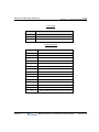
REVISION HISTORY
Release
Date
1.0
09-10
Release 1.0
Documentation Changes
Initial Release
Page No.
--
November 2010
Contents
Chapter 1
Introduction
Manual Application - - - - - - - - - - - - - - - - - - - - - - - - - - - - - - - Organization - - - - - - - - - - - - - - - - - - - - - - - - - - - - - - - - - Feature Information - - - - - - - - - - - - - - - - - - - - - - - - - - - - System Capacities - - - - - - - - - - - - - - - - - - - - - - - - - - - - - - - -
Chapter 2
1-1
1-1
1-1
1-2
Directory Number (DN)
Terms - - - - - - - - - - - - - - - - - - - - - - - - - - - - - - - - - - - - - - 2-1
Basic Features - - - - - - - - - - - - - - - - - - - - - - - - - - - - - - - - 2-2
Chapter 3
System Features
Account Code - - - - - - - - - - - - - - - - - - - - - - - - - - - - - - - - - - - 3-1
Alarm Signal/Door Bell - - - - - - - - - - - - - - - - - - - - - - - - - - - - - 3-3
Authorization Codes (Password) - - - - - - - - - - - - - - - - - - - - - - 3-5
Auto Call Release - - - - - - - - - - - - - - - - - - - - - - - - - - - - - - - - 3-6
Automatic Pause Insertion - - - - - - - - - - - - - - - - - - - - - - - - - - 3-7
Automatic Privacy/Branch Line - - - - - - - - - - - - - - - - - - - - - - - 3-8
Auto Service Mode Control - - - - - - - - - - - - - - - - - - - - - - - - - 3-10
Automatic System Daylight Savings Time - - - - - - - - - - - - - - - 3-12
Automatic System Time Synchronization - - - - - - - - - - - - - - - 3-13
Battery Back-up, Memory - - - - - - - - - - - - - - - - - - - - - - - - - - 3-14
Call Forward - - - - - - - - - - - - - - - - - - - - - - - - - - - - - - - - - - - 3-15
Call Forward, Pilot Hunt - - - - - - - - - - - - - - - - - - - - - - - - - - - 3-19
Call Forward, Preset - - - - - - - - - - - - - - - - - - - - - - - - - - - - - - 3-22
Call Park - - - - - - - - - - - - - - - - - - - - - - - - - - - - - - - - - - - - - - 3-24
Call Pick-Up - - - - - - - - - - - - - - - - - - - - - - - - - - - - - - - - - - - - 3-26
Directed Call Pick-Up - - - - - - - - - - - - - - - - - - - - - - - - - - 3-26
Group Call Pick-Up - - - - - - - - - - - - - - - - - - - - - - - - - - - - 3-28
Call Transfer - - - - - - - - - - - - - - - - - - - - - - - - - - - - - - - - - - - 3-30
Release 1.0
MBX IP Description / Operations & Programming Guide
November 2010
Contents
TOC-2
Call Transfer, Station - - - - - - - - - - - - - - - - - - - - - - - - - - Call Transfer, CO/IP - - - - - - - - - - - - - - - - - - - - - - - - - - - CO/IP Access - - - - - - - - - - - - - - - - - - - - - - - - - - - - - - - - - - CO/IP Call Time Restriction - - - - - - - - - - - - - - - - - - - - - - - - CO/IP Call Warning Tone Timer - - - - - - - - - - - - - - - - - - - - - CO/IP Queuing - - - - - - - - - - - - - - - - - - - - - - - - - - - - - - - - - Conference - - - - - - - - - - - - - - - - - - - - - - - - - - - - - - - - - - - - Conference Room - - - - - - - - - - - - - - - - - - - - - - - - - - - - Multi-Party Voice Conference - - - - - - - - - - - - - - - - - - - - Consultation Conference - - - - - - - - - - - - - - - - - - - - - - - - Unsupervised Conference - - - - - - - - - - - - - - - - - - - - - - - Customer Site Name - - - - - - - - - - - - - - - - - - - - - - - - - - - - - Data Line Security - - - - - - - - - - - - - - - - - - - - - - - - - - - - - - - Delayed CO/IP Ring - - - - - - - - - - - - - - - - - - - - - - - - - - - - - - Delayed Auto Attendant - - - - - - - - - - - - - - - - - - - - - - - - - - - Diagnostic/Maintenance - - - - - - - - - - - - - - - - - - - - - - - - - - - Dial-By-Name - - - - - - - - - - - - - - - - - - - - - - - - - - - - - - - - - - Dial Pulse to Tone Switchover - - - - - - - - - - - - - - - - - - - - - - Dialing Restrictions - - - - - - - - - - - - - - - - - - - - - - - - - - - - - - Class of Service - - - - - - - - - - - - - - - - - - - - - - - - - - - - - - Day/Timed & Night Station COS - - - - - - - - - - - - - - - - - - Temporary Station COS/Lock - - - - - - - - - - - - - - - - - - - - Walking COS - - - - - - - - - - - - - - - - - - - - - - - - - - - - - - - - Differential Ring - - - - - - - - - - - - - - - - - - - - - - - - - - - - - - - - - Digit Conversion - - - - - - - - - - - - - - - - - - - - - - - - - - - - - - - - Do Not Disturb (DND) - - - - - - - - - - - - - - - - - - - - - - - - - - - - Door Open - - - - - - - - - - - - - - - - - - - - - - - - - - - - - - - - - - - - Door Phone - - - - - - - - - - - - - - - - - - - - - - - - - - - - - - - - - - - - Emergency Call - - - - - - - - - - - - - - - - - - - - - - - - - - - - - - - - - Executive/Secretary by DN (Directory Number) - - - - - - - - - - Executive/Secretary by Exec/Sec Assignment - - - - - - - - - - - External Auto Attendant/Voice Mail - - - - - - - - - - - - - - - - - - - AA/VM Group - - - - - - - - - - - - - - - - - - - - - - - - - - - - - - - -
Release 1.0
MBX IP Description / Operations & Programming Guide
3-30
3-31
3-37
3-40
3-43
3-45
3-47
3-47
3-50
3-52
3-53
3-55
3-56
3-56
3-58
3-59
3-60
3-62
3-63
3-63
3-65
3-68
3-70
3-72
3-73
3-76
3-78
3-79
3-81
3-82
3-83
3-86
3-86
November 2010
Contents
TOC-3
In-band (DTMF) Signaling - - - - - - - - - - - - - - - - - - - - - - - 3-89
SMDI (Simplified Msg Desk Interface) - - - - - - - - - - - - - - - 3-92
Flexible Numbering Plan - - - - - - - - - - - - - - - - - - - - - - - - - - - 3-96
Green Power Save - - - - - - - - - - - - - - - - - - - - - - - - - - - - - - - 3-98
Headset Compatibility - - - - - - - - - - - - - - - - - - - - - - - - - - - - - 3-98
Hold - - - - - - - - - - - - - - - - - - - - - - - - - - - - - - - - - - - - - - - - 3-100
Hold Recall - - - - - - - - - - - - - - - - - - - - - - - - - - - - - - - - - 3-101
Automatic Hold - - - - - - - - - - - - - - - - - - - - - - - - - - - - - - 3-103
Hot Desk - - - - - - - - - - - - - - - - - - - - - - - - - - - - - - - - - - - - - 3-105
In-Room Indication - - - - - - - - - - - - - - - - - - - - - - - - - - - - - - 3-107
IP Trans-coding - - - - - - - - - - - - - - - - - - - - - - - - - - - - - - - - 3-108
Last Number Redial (LNR) - - - - - - - - - - - - - - - - - - - - - - - - 3-109
Least Cost Routing (LCR) - - - - - - - - - - - - - - - - - - - - - - - - - 3-111
Linked Station Pairs/Group - - - - - - - - - - - - - - - - - - - - - - - - 3-113
Loud Bell Control (LBC) - - - - - - - - - - - - - - - - - - - - - - - - - - 3-115
Mobile Extension - - - - - - - - - - - - - - - - - - - - - - - - - - - - - - - 3-116
Multiple Language Selection - - - - - - - - - - - - - - - - - - - - - - - 3-119
Multiple Voice Mailbox Support - - - - - - - - - - - - - - - - - - - - - 3-121
Music-On-Hold (MOH) - - - - - - - - - - - - - - - - - - - - - - - - - - - 3-122
Network Management System (NMS) - - - - - - - - - - - - - - - - 3-124
Network Security & Priority - - - - - - - - - - - - - - - - - - - - - - - - 3-125
One Digit Service - - - - - - - - - - - - - - - - - - - - - - - - - - - - - - - 3-126
Camp-On - - - - - - - - - - - - - - - - - - - - - - - - - - - - - - - - - - 3-126
Call Wait - - - - - - - - - - - - - - - - - - - - - - - - - - - - - - - - - - 3-127
Pre-defined & Custom Text Display Messages - - - - - - - - - - 3-129
Registering IP Devices & Fractional Module Tables - - - - - - - 3-133
Registration with MAC Address - - - - - - - - - - - - - - - - - - 3-133
Registration with ID/Password - - - - - - - - - - - - - - - - - - - 3-135
Registration with Station Number - - - - - - - - - - - - - - - - - 3-137
Remote Device Zone Management - - - - - - - - - - - - - - - - - - 3-139
Remote Services, Managed Net - - - - - - - - - - - - - - - - - - - - 3-139
Revertible Ring - - - - - - - - - - - - - - - - - - - - - - - - - - - - - - - - 3-141
Speed Dial - - - - - - - - - - - - - - - - - - - - - - - - - - - - - - - - - - - - 3-142
Release 1.0
MBX IP Description / Operations & Programming Guide
November 2010
Contents
TOC-4
Speed Dial Pause Insertion - - - - - - - - - - - - - - - - - - - - - Station Speed Dial - - - - - - - - - - - - - - - - - - - - - - - - - - - System Speed Dial - - - - - - - - - - - - - - - - - - - - - - - - - - - Station Call Coverage - - - - - - - - - - - - - - - - - - - - - - - - - - - System Groups - - - - - - - - - - - - - - - - - - - - - - - - - - - - - - - - Station Group - - - - - - - - - - - - - - - - - - - - - - - - - - - - - - Greeting/Queuing Tone Service - - - - - - - - - - - - - - - - - - CCR Service with Queuing Announcement - - - - - - - - - - Forward Destination, Overflow Service - - - - - - - - - - - - - Pilot Hunt Group - - - - - - - - - - - - - - - - - - - - - - - - - - - - Pick Up Group - - - - - - - - - - - - - - - - - - - - - - - - - - - - - - Push To Talk (PTT) Group - - - - - - - - - - - - - - - - - - - - - Command Conference Group - - - - - - - - - - - - - - - - - - - Interphone Group - - - - - - - - - - - - - - - - - - - - - - - - - - - - Paging Group - - - - - - - - - - - - - - - - - - - - - - - - - - - - - - Station Message Detail Recording (SMDR) - - - - - - - - - - - - Call Cost Display - - - - - - - - - - - - - - - - - - - - - - - - - - - - SMDR Call Records - - - - - - - - - - - - - - - - - - - - - - - - - - System Admin Programming - - - - - - - - - - - - - - - - - - - - - - Keyset Administration - - - - - - - - - - - - - - - - - - - - - - - - - Multi-Level Admin Access - - - - - - - - - - - - - - - - - - - - - - Web Administration - - - - - - - - - - - - - - - - - - - - - - - - - - Web User Manual - - - - - - - - - - - - - - - - - - - - - - - - - - - System DECT This
- - - - feature
- - - - - - is
- - not
- - - available
- - - - - - - -at
- -this
- - - -time
- - - ...
-System Networking - - - - - - - - - - - - - - - - - - - - - - - - - - - - - Centralized Control T-NET (LM)This-feature
- - - is- -not- available
- - - - -at -this- -time
- -...Distributed Control Network - - - - - - - - - - - - - - - - - - - - - Traffic Analysis - - - - - - - - - - - - - - - - - - - - - - - - - - - - - - - - System Time Management - - - - - - - - - - - - - - - - - - - - - - - - System Database Backup To USB - - - - - - - - - - - - - - - - - - Tenant Group - - - - - - - - - - - - - - - - - - - - - - - - - - - - - - - - - Universal Answer (UA) - - - - - - - - - - - - - - - - - - - - - - - - - - - VMIB Integrated Auto Attd/Voice Mail - - - - - - - - - - - - - - - - -
Release 1.0
MBX IP Description / Operations & Programming Guide
3-142
3-143
3-146
3-149
3-149
3-150
3-158
3-164
3-169
3-174
3-178
3-179
3-180
3-181
3-182
3-183
3-183
3-185
3-190
3-190
3-191
3-193
3-195
3-196
3-196
3-196
3-199
3-246
3-248
3-251
3-251
3-253
3-254
November 2010
Contents
TOC-5
VMIB - - - - - - - - - - - - - - - - - - - - - - - - - - - - - - - - - - - - VMIB-Auto Attendant - - - - - - - - - - - - - - - - - - - - - - - - - VMIB Voice Mail - - - - - - - - - - - - - - - - - - - - - - - - - - - - System Voice Memo - - - - - - - - - - - - - - - - - - - - - - - - - Wake-up Alarm - - - - - - - - - - - - - - - - - - - - - - - - - - - - - - - -
Chapter 4
3-254
3-254
3-257
3-276
3-279
Intercom
Direct Station Select/Busy Lamp Field (DSS/BLF) - - - - - - - - - - 4-1
Intercom Call (ICM Call) - - - - - - - - - - - - - - - - - - - - - - - - - - - - 4-2
Intercom Call Hold - - - - - - - - - - - - - - - - - - - - - - - - - - - - - - - - 4-4
Intercom Caller Controlled ICM Signaling - - - - - - - - - - - - - - - - 4-5
Intercom Lock-out - - - - - - - - - - - - - - - - - - - - - - - - - - - - - - - - 4-6
Intercom Step Call - - - - - - - - - - - - - - - - - - - - - - - - - - - - - - - - 4-7
Intercom Transfer - - - - - - - - - - - - - - - - - - - - - - - - - - - - - - - - - 4-8
INTRUSION - - - - - - - - - - - - - - - - - - - - - - - - - - - - - - - - - - - - 4-10
Message Wait/Call Back - - - - - - - - - - - - - - - - - - - - - - - - - - - 4-11
Short Message Service (SMS) - - - - - - - - - - - - - - - - - - - - 4-11
Station Message Wait/Call Back - - - - - - - - - - - - - - - - - - - 4-12
Message Wait Reminder Tone - - - - - - - - - - - - - - - - - - - - 4-15
Paging - - - - - - - - - - - - - - - - - - - - - - - - - - - - - - - - - - - - - - - 4-16
Internal/External & All Call Page - - - - - - - - - - - - - - - - - - - 4-16
Meet Me Page Answer - - - - - - - - - - - - - - - - - - - - - - - - - 4-18
VM Paging - - - - - - - - - - - - - - - - - - - - - - - - - - - - - - - - - - 4-21
Push-To-Talk Paging - - - - - - - - - - - - - - - - - - - - - - - - - - - - - 4-24
Chapter 5
CO/IP
Alternative Route Selection - - - - - - - - - - - - - - - - - - - - - - - - - - 5-1
Automatic Network Dialing - - - - - - - - - - - - - - - - - - - - - - - - - - 5-2
CO Group Access Code - - - - - - - - - - - - - - - - - - - - - - - - - - - - 5-3
CO Line Flash - - - - - - - - - - - - - - - - - - - - - - - - - - - - - - - - - - - 5-5
CO/IP Line Groups - - - - - - - - - - - - - - - - - - - - - - - - - - - - - - - - 5-7
CO Line Service - - - - - - - - - - - - - - - - - - - - - - - - - - - - - - - - - - 5-9
Incoming CO Line Option - - - - - - - - - - - - - - - - - - - - - - - - - 5-9
Outgoing CO Line Option - - - - - - - - - - - - - - - - - - - - - - - - 5-14
Alternate Incoming CO Service - - - - - - - - - - - - - - - - - - - 5-19
Release 1.0
MBX IP Description / Operations & Programming Guide
November 2010
Contents
TOC-6
Alternate Outgoing CO Service - - - - - - - - - - - - - - - - - - - Digit Sending Mode - - - - - - - - - - - - - - - - - - - - - - - - - - - CO COS - - - - - - - - - - - - - - - - - - - - - - - - - - - - - - - - - - - DID Name Service - - - - - - - - - - - - - - - - - - - - - - - - - - - - Incoming CO Line Holiday Service - - - - - - - - - - - - - - - - - DID/DISA Restriction - - - - - - - - - - - - - - - - - - - - - - - - - - CO/IP LINE PRESET FORWARD - - - - - - - - - - - - - - - - - - - - CO OWN CODE SERVICE - - - - - - - - - - - - - - - - - - - - - - - - - CO/IP Ring Assignment - - - - - - - - - - - - - - - - - - - - - - - - - - - CO Line Release Guard Time - - - - - - - - - - - - - - - - - - - - - - - CO Ring Detect - - - - - - - - - - - - - - - - - - - - - - - - - - - - - - - - - CO Transit Service - - - - - - - - - - - - - - - - - - - - - - - - - - - - - - Dial Pulse Signaling - - - - - - - - - - - - - - - - - - - - - - - - - - - - - - Direct Inward Dial (DID) - - - - - - - - - - - - - - - - - - - - - - - - - - - Direct Inward System Access (DISA) - - - - - - - - - - - - - - - - - - Dual Tone Multi-Frequency (DTMF) Signal Sending - - - - - - - H.323 Multi Route Service - - - - - - - - - - - - - - - - - - - - - - - - - Incoming Calling Line ID (ICLID) Call Routing - - - - - - - - - - - IP Trunking - - - - - - - - - - - - - - - - - - - - - - - - - - - - - - - - - - - - H.323 v4 Service - - - - - - - - - - - - - - - - - - - - - - - - - - - - - Session Initiation Protocol (SIP) Service - - - - - - - - - - - - - IP WAN Dialing After Answer - - - - - - - - - - - - - - - - - - - - - - - Integrated Service Digital Network (ISDN) - - - - - - - - - - - - - - ISDN Advice of Charge (AOC) - - - - - - - - - - - - - - - - - - - - Calling/Called Party Identification (CLIP/COLP) - - - - - - - Keypad Facility - - - - - - - - - - - - - - - - - - - - - - - - - - - - - - Multiple Subscriber Number (MSN) - - - - - - - - - - - - - - - - ISDN CLI - - - - - - - - - - - - - - - - - - - - - - - - - - - - - - - - - - - ISDN Supplementary Services - - - - - - - - - - - - - - - - - - - - - - ISDN Call Deflection - - - - - - - - - - - - - - - - - - - - - - - - - - - Representative CLI Service - - - - - - - - - - - - - - - - - - - - - - - - -
Chapter 6
5-25
5-28
5-29
5-29
5-31
5-34
5-35
5-37
5-38
5-41
5-42
5-43
5-45
5-46
5-51
5-55
5-56
5-57
5-60
5-60
5-62
5-63
5-65
5-65
5-69
5-71
5-72
5-75
5-78
5-78
5-79
Digital Phone
Auto Called Number Redial (ACNR) - - - - - - - - - - - - - - - - - - - - 6-2
Release 1.0
MBX IP Description / Operations & Programming Guide
November 2010
Contents
TOC-7
Auto Release of [Speaker] - - - - - - - - - - - - - - - - - - - - - - - - - - 6-4
Automatic Speaker Select - - - - - - - - - - - - - - - - - - - - - - - - - - - 6-4
Background Music (BGM) - - - - - - - - - - - - - - - - - - - - - - - - - - - 6-6
Call Log Display - - - - - - - - - - - - - - - - - - - - - - - - - - - - - - - - - - 6-7
CO Line Name Display - - - - - - - - - - - - - - - - - - - - - - - - - - - - - 6-8
One Time DND - - - - - - - - - - - - - - - - - - - - - - - - - - - - - - - - - - 6-9
Group Listening - - - - - - - - - - - - - - - - - - - - - - - - - - - - - - - - - 6-10
Intercom Signaling Mode - - - - - - - - - - - - - - - - - - - - - - - - - - 6-11
Mute - - - - - - - - - - - - - - - - - - - - - - - - - - - - - - - - - - - - - - - - - 6-13
Off-Hook Signaling - - - - - - - - - - - - - - - - - - - - - - - - - - - - - - - 6-14
On-Hook Dialing - - - - - - - - - - - - - - - - - - - - - - - - - - - - - - - - - 6-15
Prime Line Immediately/Delayed - - - - - - - - - - - - - - - - - - - - - 6-16
Differential Ring - - - - - - - - - - - - - - - - - - - - - - - - - - - - - - - - - 6-17
Saved Number Redial (SNR) - - - - - - - - - - - - - - - - - - - - - - - - 6-18
Speakerphone - - - - - - - - - - - - - - - - - - - - - - - - - - - - - - - - - - 6-19
Station Flexible Buttons - - - - - - - - - - - - - - - - - - - - - - - - - - - 6-21
Station Flexible LED Flash Rates - - - - - - - - - - - - - - - - - - - - - 6-23
Station ICLID Call Routing - - - - - - - - - - - - - - - - - - - - - - - - - 6-24
Station User Programming & Codes - - - - - - - - - - - - - - - - - - - 6-25
Two-Way Record - - - - - - - - - - - - - - - - - - - - - - - - - - - - - - - - 6-28
Answering Machine Emulation (AME) - - - - - - - - - - - - - - - - - 6-31
Voice Over - - - - - - - - - - - - - - - - - - - - - - - - - - - - - - - - - - - - 6-33
Chapter 7
Attendants
Attendant Group - - - - - - - - - - - - - - - - - - - - - - - - - - - - - - - - - - 7-1
Night Attendant Group - - - - - - - - - - - - - - - - - - - - - - - - - - - - 7-10
Greeting/Queuing Tone Service - - - - - - - - - - - - - - - - - - - - - - 7-15
CCR Service for Attendant Queuing Annoucement - - - - - - - - 7-20
Forward Destination, Overflow Service - - - - - - - - - - - - - - - - - 7-25
Attendant Recall - - - - - - - - - - - - - - - - - - - - - - - - - - - - - - - - - 7-30
Attendant Station Program Codes - - - - - - - - - - - - - - - - - - - - 7-32
Attendant Call/Queuing - - - - - - - - - - - - - - - - - - - - - - - - - - - - 7-36
Day/Night/Timed Ring Mode - - - - - - - - - - - - - - - - - - - - - - - - 7-37
DSS/DLS Consoles - - - - - - - - - - - - - - - - - - - - - - - - - - - - - - 7-40
Release 1.0
MBX IP Description / Operations & Programming Guide
November 2010
Contents
TOC-8
EZ-Attendant - - - - - - - - - - - - - - - - - - - - - - - - - - - - - - - - - - - System Clock Set - - - - - - - - - - - - - - - - - - - - - - - - - - - - - - - USB Upgrade - - - - - - - - - - - - - - - - - - - - - - - - - - - - - - - - - - USB DB Up/Download From/To USB - - - - - - - - - - - - - - - - - -
Chapter 8
7-41
7-42
7-44
7-45
Single Line Telephone
Broker Call - - - - - - - - - - - - - - - - - - - - - - - - - - - - - - - - - - - - - - 8-1
Hook-Flash Mode - - - - - - - - - - - - - - - - - - - - - - - - - - - - - - - - - 8-3
Howler Tone - - - - - - - - - - - - - - - - - - - - - - - - - - - - - - - - - - - - - 8-4
SLT Message Wait Indication - - - - - - - - - - - - - - - - - - - - - - - - - 8-5
SLT Name Registration - - - - - - - - - - - - - - - - - - - - - - - - - - - - - 8-6
Chapter 9
SIP Phone
SIP Terminal Registration - - - - - - - - - - - - - - - - - - - - - - - - - - - - 9-1
SIP Name Registration - - - - - - - - - - - - - - - - - - - - - - - - - - - - - - 9-2
SIP Placing Calls - - - - - - - - - - - - - - - - - - - - - - - - - - - - - - - - - - 9-2
SIP Call Pick-Up - - - - - - - - - - - - - - - - - - - - - - - - - - - - - - - - - - 9-3
SIP Hold Call - - - - - - - - - - - - - - - - - - - - - - - - - - - - - - - - - - - - - 9-3
SIP Transfer Call - - - - - - - - - - - - - - - - - - - - - - - - - - - - - - - - - - 9-4
SIP Call Forward - - - - - - - - - - - - - - - - - - - - - - - - - - - - - - - - - - 9-4
SIP Do Not Disturb (DND) - - - - - - - - - - - - - - - - - - - - - - - - - - - 9-5
SIP 3-Party Conference - - - - - - - - - - - - - - - - - - - - - - - - - - - - - 9-5
SIP Call Wait/Broker Call - - - - - - - - - - - - - - - - - - - - - - - - - - - - 9-5
SIP SMS - - - - - - - - - - - - - - - - - - - - - - - - - - - - - - - - - - - - - - - - 9-6
SIP Voice Mail Notification - - - - - - - - - - - - - - - - - - - - - - - - - - - 9-6
SIP Video Call - - - - - - - - - - - - - - - - - - - - - - - - - - - - - - - - - - - - 9-6
Chapter 10
ACD (Automatic Call Distribution)
ACD Basic Feature - - - - - - - - - - - - - - - - - - - - - - - - - - - - - - - - 7-1
ACD Group Service Status - - - - - - - - - - - - - - - - - - - - - - - - - - - 7-9
ACD Call Distribution by Priority - - - - - - - - - - - - - - - - - - - - - - 7-16
ACD Call Queuing Service - - - - - - - - - - - - - - - - - - - - - - - - - - 7-21
CCR Service During ACD Announcement - - - - - - - - - - - - - - - 7-28
ACD Agent State - - - - - - - - - - - - - - - - - - - - - - - - - - - - - - - - - 7-33
ACD Agent Log-in / Log-out Default Setting - - - - - - - - - - - - - - 7-39
Release 1.0
MBX IP Description / Operations & Programming Guide
November 2010
Contents
TOC-9
ACD Call Indication - - - - - - - - - - - - - - - - - - - - - - - - - - - - - - 7-44
ACD Group Supervisor Functions - - - - - - - - - - - - - - - - - - - - 7-50
ACD Group Call Traffic - - - - - - - - - - - - - - - - - - - - - - - - - - - - 7-59
Appendix A
System Programming Tables
Initialization - - - - - - - - - - - - - - - - - - - - - - - - - - - - - - - - - - - - - A-1
Program Menu Structure - - - - - - - - - - - - - - - - - - - - - - - - - - - - A-2
Administration Menu Table - - - - - - - - - - - - - - - - - - - - - - - A-2
S/W Upgrade - - - - - - - - - - - - - - - - - - - - - - - - - - - - - - - - - A-6
System Management - - - - - - - - - - - - - - - - - - - - - - - - - - - A-6
Station Admin Programming - - - - - - - - - - - - - - - - - - - - - - - - - A-7
LCD & Button Functions - - - - - - - - - - - - - - - - - - - - - - - - - A-7
Alphanumeric Data Entries - - - - - - - - - - - - - - - - - - - - - - - A-7
Required Data Entries - - - - - - - - - - - - - - - - - - - - - - - - - - - A-7
Data Entry Mode - - - - - - - - - - - - - - - - - - - - - - - - - - - - - - - - - A-8
Procedures for Data Entry - - - - - - - - - - - - - - - - - - - - - - - - A-8
PRE-PROGRAMMED DATA - PGM Codes 100 to 108 - - - - - - A-9
Location Program (PGM 100) - - - - - - - - - - - - - - - - - - - - - - A-9
Slot Assignment (PGM 101) - - - - - - - - - - - - - - - - - - - - - - A-11
Logical Slot Assignment (PGM 103) - - - - - - - - - - - - - - - - A-12
DECT/IP Phone/SIP Phone Port Assignment (PGM 104) - A-12
IP Phone/Phontage Registration Table (PGM 106) - - - - - - A-13
DTIM/SLTM Registration Table (PGM 107) - - - - - - - - - - - A-14
IP Address Plan (PGM 108) - - - - - - - - - - - - - - - - - - - - - - A-14
System Information (PGM 109) - - - - - - - - - - - - - - - - - - - A-15
NUMBERING PLAN DATA - PGM Codes 110 to 116 - - - - - - A-16
Numbering Plan Type (PGM 110) - - - - - - - - - - - - - - - - - - A-16
System Numbering Plan (PGM 111) - - - - - - - - - - - - - - - - A-16
Flexible Station Number (PGM 112) - - - - - - - - - - - - - - - - A-17
FEATURE NUMBERING PLAN (PGM 113) - - - - - - - - - - - - - A-18
CO Group Access Code (PGM 114) - - - - - - - - - - - - - - - - A-22
Station Group Number (PGM 115) - - - - - - - - - - - - - - - - - A-22
ACD Group Number (PGM 118) - - - - - - - - - - - - - - - - - - - A-23
Release 1.0
MBX IP Description / Operations & Programming Guide
November 2010
Contents
TOC-10
STATION DATA - PGM Codes 120-152 - - - - - - - - - - - - - - - Station Type (PGM 120) - - - - - - - - - - - - - - - - - - - - - - - Station Port Attributes (PGM 121-124) - - - - - - - - - - - - - Station Flexible Button Assignment (PGM 126) - - - - - - - Station Number Information (PGM 130) - - - - - - - - - - - - Station Number Attributes - PGM 131-135 - - - - - - - - - - Station Class of Service (PGM 137) - - - - - - - - - - - - - - - Station Auto Attributes (PGM 138) - - - - - - - - - - - - - - - - Station Preset Call Forward (PGM 142) - - - - - - - - - - - - Station Call Forward (PGM 143) - - - - - - - - - - - - - - - - - Station VMIB Attribute (PGM 145) - - - - - - - - - - - - - - - - Station Mobile Phone Attribute (PGM 146) - - - - - - - - - - CO/IP Group Access (PGM 150) - - - - - - - - - - - - - - - - - Internal Page Group Access (PGM 151) - - - - - - - - - - - - Command Group Access (PGM 152) - - - - - - - - - - - - - - CO LINE DATA - PGM 160-181 - - - - - - - - - - - - - - - - - - - - CO Attribute I, II, III - PGM 160-162 - - - - - - - - - - - - - - - CO CID Attributes (PGM 163) - - - - - - - - - - - - - - - - - - - CO Incoming Attribute I, II - PGM 165-166 - - - - - - - - - - CO Ring Assignment (PGM 167) - - - - - - - - - - - - - - - - - Incoming CO Normal/DISA Attributes (PGM 168) - - - - - CO Incoming Alternate Destination (PGM 169) - - - - - - - CO Outgoing Attributes I (PGM 170) - - - - - - - - - - - - - - CO Outgoing Attributes II (PGM 171) - - - - - - - - - - - - - - CO Outgoing Alternate Destination (PGM 173) - - - - - - - CO Outgoing Inter-Digit Timer (PGM 174) - - - - - - - - - - CO DTMF Sending Delay Timer (PGM 175) - - - - - - - - - CO COS Assignment (PGM 177) - - - - - - - - - - - - - - - - - CO to CO Transfer Attributes (PGM 179) - - - - - - - - - - - CO Group Access Code Attribute (PGM 180) - - - - - - - - Alternate Ring Assignment (PGM 181) - - - - - - - - - - - - - SYSTEM GROUP DATA - PGM 200-215 - - - - - - - - - - - - - - Station Group (PGM 200) - - - - - - - - - - - - - - - - - - - - - - -
Release 1.0
MBX IP Description / Operations & Programming Guide
A-24
A-24
A-25
A-30
A-32
A-33
A-39
A-40
A-41
A-42
A-43
A-44
A-45
A-45
A-46
A-46
A-46
A-50
A-51
A-54
A-55
A-55
A-56
A-59
A-60
A-61
A-62
A-63
A-63
A-64
A-66
A-66
A-67
November 2010
Contents
TOC-11
Station Group Greeting/Queuing Attributes (PGM 201) - - - A-68
Station Group Attributes (PGM 202) - - - - - - - - - - - - - - - - A-71
Voice Mail Group Attributes (PGM 203) - - - - - - - - - - - - - - A-72
Pick Up Group (PGM 204) - - - - - - - - - - - - - - - - - - - - - - - A-73
Page Group (PGM 205) - - - - - - - - - - - - - - - - - - - - - - - - - A-73
Command Call Group (PGM 206) - - - - - - - - - - - - - - - - - - A-74
PTT Group (PGM 208) - - - - - - - - - - - - - - - - - - - - - - - - - A-75
Interphone Group (PGM 209) - - - - - - - - - - - - - - - - - - - - - A-76
Pilot Hunt Group (PGM 210) - - - - - - - - - - - - - - - - - - - - - A-76
Pilot Hunt Group Forward Attribute (PGM 211) - - - - - - - - A-77
ACD Group (PGM 212) - - - - - - - - - - - - - - - - - - - - - - - - - A-78
ACD Group Attribute I (PGM 213) - - - - - - - - - - - - - - - - - - A-80
ACD Group Attribute II (PGM 214) - - - - - - - - - - - - - - - - - A-82
ACD Group Announcement (PGM 215) - - - - - - - - - - - - - - A-84
SYSTEM DATA - PGM 220-242 - - - - - - - - - - - - - - - - - - - - - A-85
System Timers I (PGM 220) - - - - - - - - - - - - - - - - - - - - - - A-85
System Timers II (PGM 221) - - - - - - - - - - - - - - - - - - - - - A-86
System Timers II (PGM 222) - - - - - - - - - - - - - - - - - - - - - A-87
System Attributes (PGM 223) - - - - - - - - - - - - - - - - - - - - - A-88
System Password (PGM 226) - - - - - - - - - - - - - - - - - - - - A-89
Alarm Attributes (PGM 227) - - - - - - - - - - - - - - - - - - - - - - A-90
External Control Contacts (PGM 228) - - - - - - - - - - - - - - - A-90
Music Sources (PGM 229) - - - - - - - - - - - - - - - - - - - - - - - A-91
RS-232 Port Settings (PGM 230) - - - - - - - - - - - - - - - - - - A-92
Serial Port Function Selections (PGM 231) - - - - - - - - - - - A-93
SMDR Attributes (PGM 232) - - - - - - - - - - - - - - - - - - - - - A-94
System Date, Time (PGM 233) - - - - - - - - - - - - - - - - - - - - A-97
Button LED Flash Rate (PGM 234) - - - - - - - - - - - - - - - - - A-98
ISDN PPP Web Admin Attributes (PGM 235) - - - - - - - - - A-102
Mobile Attributes (PGM 236) - - - - - - - - - - - - - - - - - - - - A-102
One Digit Service Attributes (PGM 237) - - - - - - - - - - - - A-103
Dummy Dial Tone Digit (PGM 240) - - - - - - - - - - - - - - - - A-104
Executive/Secretary Assign (PGM 241) - - - - - - - - - - - - - A-104
Release 1.0
MBX IP Description / Operations & Programming Guide
November 2010
Contents
TOC-12
Executive-Executive Access (PGM 242) - - - - - - - - - - - - - A-105
TABLES DATA - PGM 250-269 - - - - - - - - - - - - - - - - - - - - - - A-106
Toll Tables (PGM 250) - - - - - - - - - - - - - - - - - - - - - - - - - A-106
Digit Conversion Tables (PGM 251) - - - - - - - - - - - - - - - - A-107
Digit Conversion Options (PGM 252) - - - - - - - - - - - - - - - A-109
Time Table Attributes (PGM 253) - - - - - - - - - - - - - - - - - - A-110
Weekly Time Table (PGM 254) - - - - - - - - - - - - - - - - - - - A-111
LCR Time Table Attributes (PGM 255) - - - - - - - - - - - - - - A-112
Holiday Time Table (PGM 256) - - - - - - - - - - - - - - - - - - - A-113
System Speed Table (PGM 257) - - - - - - - - - - - - - - - - - - A-113
Emergency Code Table Attributes (PGM 258) - - - - - - - - - A-114
Announcement Table (PGM 259) - - - - - - - - - - - - - - - - - - A-114
Customer Call Routing Table (PGM 260) - - - - - - - - - - - - A-115
Customer Call Routing Table (PGM 262) - - - - - - - - - - - - A-115
CLI Conversion Table (PGM 263) - - - - - - - - - - - - - - - - - A-116
CLI Conversion Table (PGM 264) - - - - - - - - - - - - - - - - - A-117
Ring Table (PGM 265) - - - - - - - - - - - - - - - - - - - - - - - - - A-118
Ring Freq/Cadence Table (PGM 266) - - - - - - - - - - - - - - A-119
Voice Mail Dialing Table (PGM 269) - - - - - - - - - - - - - - - - A-119
TENANTS DATA - PGM 270-290 - - - - - - - - - - - - - - - - - - - - A-121
Attendant Group - PGM 270-272 - - - - - - - - - - - - - - - - - - A-121
Night Attendant Group - PGM 275-277 - - - - - - - - - - - - - - A-126
Tenant Attributes - PGM 280-281 - - - - - - - - - - - - - - - - - A-131
Tenant Group Access (PGM 283) - - - - - - - - - - - - - - - - - A-134
CO Call Restriction - PGM 284-285 - - - - - - - - - - - - - - - - A-134
Call Prefix Table - PGM 286-288 - - - - - - - - - - - - - - - - - - A-137
Tenant Tone Table (PGM 290) - - - - - - - - - - - - - - - - - - - A-138
BOARD DATA - PGM 300-310 - - - - - - - - - - - - - - - - - - - - - - A-143
ISDN Board Attribute (PGM 300) - - - - - - - - - - - - - - - - - - A-143
ISDN Board - Clock Priority (PGM 301) - - - - - - - - - - - - - A-144
IPP Board Attribute (PGM 305) - - - - - - - - - - - - - - - - - - - A-144
Reset Board (PGM 310) - - - - - - - - - - - - - - - - - - - - - - - - A-145
NETWORKING DATA - PGM 320-321 - - - - - - - - - - - - - - - - - A-145
Release 1.0
MBX IP Description / Operations & Programming Guide
November 2010
Contents
TOC-13
Net Basic Attribute (PGM 320) - - - - - - - - - - - - - - - - - - Net Numbering Plan Table (PGM 321) - - - - - - - - - - - - ... 330-335 - - - TNET, CENTRALIZED NETWORKING - PGM
me
i
t
his - - - - - - - - - - - - - - - TNET Basic Attributes (PGM 330)
at t
e
l
ab 331) - - - - - - - - - - - - - - - - - TNET CM Attributes (PGM
vail
a
t
o
FoPSTN Attributes
is n (PGM 333) - - - - - - - - - - - - - - - - - - e
r
u
t
Board
TNET
Attributes (PGM 334) - - - - - - - - - - - - - - - a
s fe
hiPhone
TIP
TNET Attributes (PGM 335) - - - - - - - - - - - - - H.323 DATA - PGM 360-363 - - - - - - - - - - - - - - - - - - - - - - H.323 Routing Attributes (PGM 360) - - - - - - - - - - - - - - H.323 Call Setup Info (PGM 361) - - - - - - - - - - - - - - - - H.323 Incoming Attributes (PGM 362) - - - - - - - - - - - - - GK Setup Info (PGM 363) - - - - - - - - - - - - - - - - - - - - - GAIN & CADENCE CONTROL - PGM 400-440 - - - - - - - - DKT RX Gain (PGM 400) - - - - - - - - - - - - - - - - - - - - - - SLT RX Gain (PGM 401) - - - - - - - - - - - - - - - - - - - - - - DECT RX Gain (PGM 402) - - - - - - - - - - - - - - - - - - - - IP-Phone RX Gain (PGM 403) - - - - - - - - - - - - - - - - - - Analog CO RX Gain (PGM 404) - - - - - - - - - - - - - - - - - Digital CO RX Gain (PGM 405) - - - - - - - - - - - - - - - - - VMIB RX Gain (PGM 406) - - - - - - - - - - - - - - - - - - - - - External Page RX Gain (PGM 407) - - - - - - - - - - - - - - - DSP RX Gain (PGM 415) - - - - - - - - - - - - - - - - - - - - - RTP RX Gain (PGM 420-426) - - - - - - - - - - - - - - - - - - RTP RX Gain (PGM 430-436) - - - - - - - - - - - - - - - - - - SLT Ring Cadence (PGM 440) - - - - - - - - - - - - - - - - - - ACNR Tone Cadence (PGM 441) - - - - - - - - - - - - - - - - DB INITIALIZATION (PGM 499) - - - - - - - - - - - - - - - - - - - -
Appendix B
A-145
A-146
A-147
A-147
A-148
A-149
A-150
A-150
A-150
A-150
A-151
A-152
A-153
A-154
A-154
A-154
A-155
A-156
A-156
A-157
A-158
A-158
A-159
A-160
A-163
A-166
A-168
A-168
Quick Reference
DATABASE INDEX - - - - - - - - - - - - - - - - - - - - - - - - - - - - - - - B-1
DEFAULT NUMBERING PLAN - - - - - - - - - - - - - - - - - - - - - - - B-8
FIXED FUNCTION/USER PROGRAM CODES - - - - - - - - - - - B-17
Release 1.0
MBX IP Description / Operations & Programming Guide
November 2010
Contents
TOC-14
DEFAULT VALUES - - - - - - - - - - - - - - - - - - - - - - - - - - - - - - B-21
USER ENTRY GUIDES - - - - - - - - - - - - - - - - - - - - - - - - - - - B-105
Alphanumeric Entry Chart - - - - - - - - - - - - - - - - - - - - - - - B-105
Alternate Alphanumeric Entry Chart - - - - - - - - - - - - - - - - B-106
Index
Release 1.0
MBX IP Description / Operations & Programming Guide
November 2010
Manual Application
1-1
Chapter 1: Introduction
Chapter 1
Introduction
This chapter provides a table that shows the system capacities available in the MBX IP System
Software.
Manual Application
Organization
Features are arranged alphabetically in seven different major groupings that follow two basic
chapters (1 - Introduction) and (2 - Directory Number):
3) System features
4) Intercom features
5) CO/IP features
6) Digital Phone features
7) Attendant features
8) Single Line Telephone features
9) SIP features
This book also includes two appendices, one with System Programming tables (Appendix A)
and the other with Quick Reference tables (Appendix B).
Feature Information
Each section is an alphabetical listing of features with the description and operation of each.
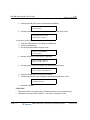
The structure is divided into 6 parts when they apply:
Release 1.0
•
The description below the chapter title explains the nature of those features.
•
CONDITIONS: explains known interactions and constraints related to the feature.
•
OPERATIONS: gives detailed step-by-step operation of the feature for Digital Phones
and SLTs.
•
PROGRAMMING: lists database entries that may be required for proper feature
operation.
•
RELATED FEATURES: lists related information to aid in understanding the feature.
•
HARDWARE: lists hardware required for proper feature operation.
MBX IP Description / Operations & Programming Guide
November 2010
System Capacities
1-2
Chapter 1: Introduction
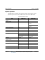
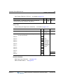
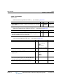
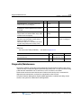
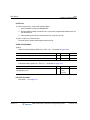
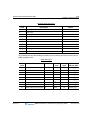
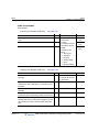
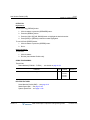
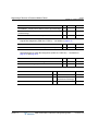
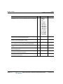
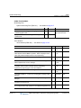
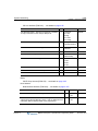
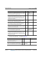
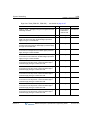
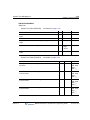
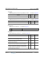
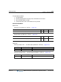
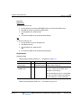
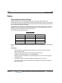
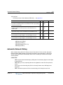
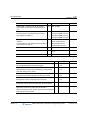
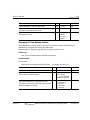
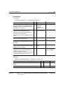
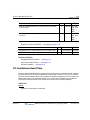
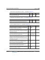
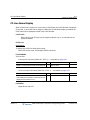
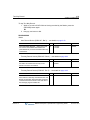
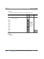
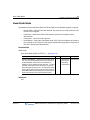
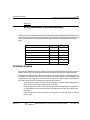
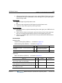
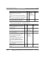
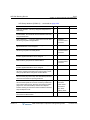
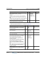
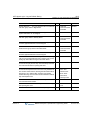
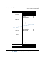
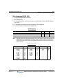
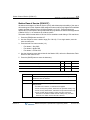
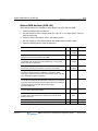
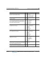
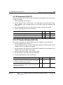
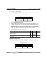
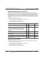
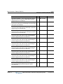
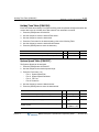
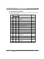
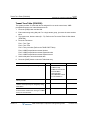
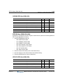
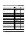
System Capacities
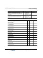
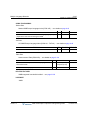
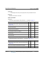
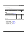
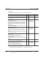
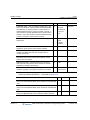
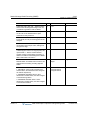
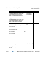
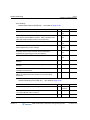
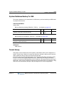
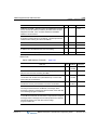
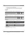
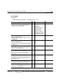
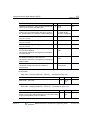
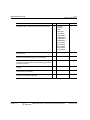
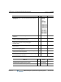
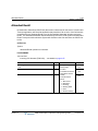
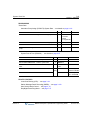
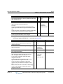
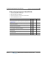
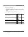
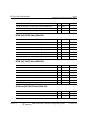
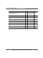
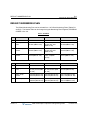
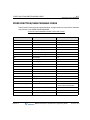
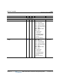
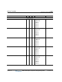
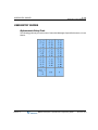
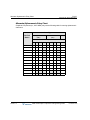
The MBX IP Series is available in the configurations shown in the table below. Total port
capacities range from the 50 channel at MBX IP-100 to 400 channel at MBX IP-300.
SYSTEM CAPACITY CHART
Items
MBX IP-100
MBX IP-300
Rack No.
2
3
Slot No. per Rack
6
6
Total Port (Extension + CO line)
168
414 (if IP Phone/DECT not
included)
564 (if IP Phone/DECT
included)
Number of extension Port
120
324
Number of extension
180 (Ext 120 + DN 60)
648 (324 x 2)
Number of CO Line
60
240
Number of Tenant Group
5
9
Numbering Plan
Extension: 8 Digits
Extension: 8 Digits
Feature: 8 Digits
Feature: 8 Digits
Trunk: 8 Digits
Trunk: 8 Digits
Attendant
5/Tenant
5/Tenant
DSS/BLF Console
5
5
Conference Members
3 Groups/13 Members
3 Groups/13 Members
Internal Page Zone
15
30
System Speed Dial
1000
2000
(32 digits)
(32 digits)
50 (32 digits)
50 (32 digits)
Station Speed Dial
Call Log (Outgoing/Incoming/Missed Call) 100 (32 digits) (Not protected)
Release 1.0
100 (32 digits) (Not protected)
MBX IP Description / Operations & Programming Guide
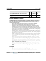
November 2010
System Capacities
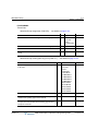
1-3
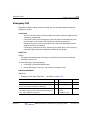
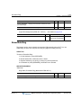
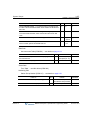
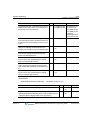
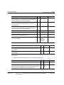
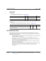
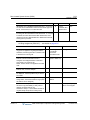
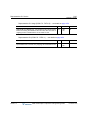
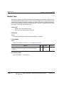
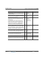
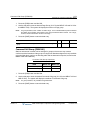
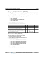
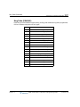
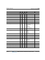
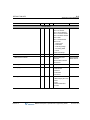
Chapter 1: Introduction
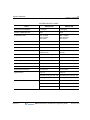
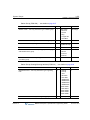
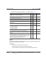
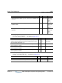
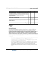
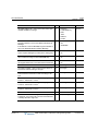
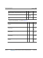
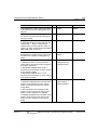
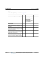
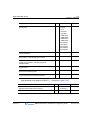
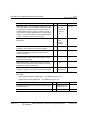
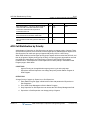
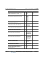
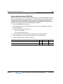
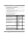
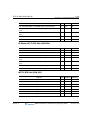
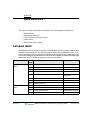
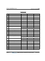
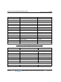
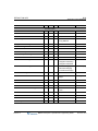
SYSTEM CAPACITY CHART
Items
MBX IP-100
MBX IP-300
Save Number Redial(SNR)
1 (32 digits)
1 (32 digits)
Number of SMDR Records
5000
5000
Authorization Code
Max. 12 Digits
180: Extension
400: System
Max. 12 Digits
648: Extension
800: System
CO Group No
24
72
Station Group
50 member/Group)
50 member/Group
Pickup Group
20 (100 member/Group)
50 (100 member/Group)
Command Call Group
10 (12 member + 1
initiator/Group)
10 (12 member + 1 initiator
/Group)
Interphone Group
10 (10 member/Group)
10 (10 member/Group)
Page Group
15 (50 member/Group)
30 (50 member/Group)
PTT Group
10 (50 member/Group)
10 (50 member/Group)
Conference Room
9
9
Number of Hot Desk Agent
60
324
Station Name Information
16 Characters
16 Characters
Digit Restriction
COS: 16
COS: 16
Allow/Deny Entry per COS: 100
Allow/Deny Entry per COS: 100
Max. Digit: 16
Max. Digit: 16
Table No: 5
Table No: 5
Number of Digit: 16
Number of Digit: 16
300 per 1 table
300 per 1 table
Digit Translation
Release 1.0
MBX IP Description / Operations & Programming Guide
November 2010
THIS PAGE INTENTIONALLY LEFT BLANK.
2-1
Chapter 2: Directory Number (DN)
Chapter 2
Directory Number (DN)
Directory Number (DN) is the telephone number for internal users, which can be used
exclusively by only one station or can be shared by multiple stations.
The basic idea of providing the DN feature is not only to assign one telephone number to one
physical telephone, but also to allow one telephone number to be shared and used by multiple
physical stations.
So, if one DN is contained by a variety of multi-functional terminals or analog telephones, all
those physical stations can be assumed as one logical station as if several analog telephone
sets can be connected to one physical line.
In another way, one physical telephone can have multiple DNs allowing for additional outgoing
and incoming calls.
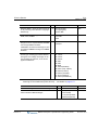
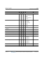
Terms
TYPES OF DN
• SADN-NORMAL : Single-Assign Directory Number (SADN) that can be used by only one station.
• SADN-HOTDESK : Single-Assign Directory Number (SADN) for Hot Desk Usage.
• MADN: Multi-Assign Directory Number (MADN) that can be used by one or multiple stations.
CATEGORY OF DN
• My-DN (M-DN): each station must have at least one unique number that cannot be used by another
station (minimum requirement, automatically assigned by board configuration). Otherwise, it is not
possible to make outgoing calls or receive incoming calls.
• Sub-DN (S-DN): station can have more numbers but M-DN. All numbers except M-DN are called
S-DN.
NOTE:
S-DN can be shared by other stations if it is MADN type.
PRIME DN
• If multiple numbers are used by a station, one DN can be selected to have higher priority over
others. When only one number exists, it becomes P-DN, which will be seized first for outgoing calls,
answered first if there's are multiple incoming calls, and used for idle status display for DND,
Forward, Absent Message and so on that can be set independently for each DN.
Release 1.0
MBX IP Description / Operations & Programming Guide
November 2010
2-2
Chapter 2: Directory Number (DN)
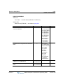
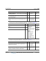
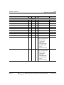
RELATED PROGRAMMING
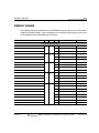
System Data
Numbering Plan, Station Number (PGM 112) … see details on page A-17
Station Data
Station Number Type (PGM 130 - Flex 1) … see details on page A-32
MADN Member (PGM 130 - Flex 2) … see details on page A-32
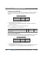
Prime Number Button (PGM123 - Flex 1) … see details on page A-27
PGM 123
BTN
PRIME NUMBER BTN -- among My-DN and several Sub-DNs
which are assigned to station flex buttons, determines the
first-seized DN when the user initiates a call. If prime button is not
set of invalid, the system scans sequentially from flexible button 1
to flexible Button 48 and take the unused and valid flexible button
as prime button NOTE: DN buttons of associated DSS box cannot
be a prime number button.
1
RANGE
01-48
DEFAULT
01
Basic Features
To use DN features, or to receive incoming calls or make outgoing calls, DN must be
programmed on a Flex button, except in the case of an analog phone (does not have flex
buttons). One DN is stored in each station by default, which is M-DN. If there is no DN button
at all, it is not possible to call a number or get a call from others.
Making Calls
When making outgoing calls, a Station User can select a DN number either by pressing
the appropriate DN flex button, by going off-hook using the handset, or by dialing while the
phone is on-hook.
P-DN is seized automatically if the DN button is not explicitly pressed as in the case of
going off-hook or on-hook dialing. However, if the P-DN is busy at that time (P-DN can be
shared by other stations), the first idle DN button is selected in the order of button number
(button 1 first, button 2 second, etc.).
Once a DN is selected for an outgoing call, the tenant group number, calling station
number, CLI, COS and other DN-related information are applied for the duration of the
call. For example, if a different DN is selected for two outgoing calls, it is possible to have
different tenant groups or COS for each call.
Release 1.0
MBX IP Description / Operations & Programming Guide
November 2010
2-3
Chapter 2: Directory Number (DN)
Receiving Calls
A physical station can receive additional calls showing on DN buttons, or through other
available DN numbers that are stored in that station, even while on a call. However, if the
DN is in use, it is not possible to receive a call through that DN number.
NOTE:
the status of a physical station and each DN is maintained independantly.
If the Station is idle, the normal ring will be provided. Otherwise, off-hook signaling is
activated. The Station User can answer an incoming call by pressing the flashing DN flex
button, or by going off-hook without selecting a DN flex button. If there are multiple
incoming calls at the same time, going off-hook allows the user to seize P-DN if it is
ringing, or to seize first ringing DN in the order of button number (btn 1 first, btn 2 second).
Even when there are incoming calls at a station, the User can make an outgoing call by
pressing an idle DN button and dialing the called party number.
P-DN Feature
P-DN is automatically seized first when a station user goes off-hook or dials while on-hook
when receiving or making calls. P-DN can be either M-DN or S-DN. If P-DN is not
assigned explicitly, the first DN button becomes P-DN in the order of button number.
The same DN can be used as P-DN for multiple stations. If the state of shared P-DN is
changed in this case, the status of P-DN will be updated to all the stations that have the
shared P-DN. For example, DND, call forward, and other DN-based status notifications
will be displayed at all same DN-programmed stations.
LED of DN Button
LED states of DN buttons are as follows:
•
Green ON: DN being used by my station
•
Red ON: DN being used by another station
•
Amber flash: Held DN
•
Green Flash: Ringing DN
•
Red Flash: DN in DND status or DN in Call Forward
DN Tenant Group/COS
Each DN can be programmed with its own Tenant group or COS information. So, Tenant
group and COS can be different for each call depending on the DN used for the calls.
If a station has DN buttons with different tenant groups, the station can make and receive
calls using the different tenant groups.
Additionally, if the DN buttons have different COS, a station can have different COS
according to the DN button selected.
Release 1.0
MBX IP Description / Operations & Programming Guide
November 2010
2-4
Chapter 2: Directory Number (DN)
Branch Line
When a station is using a MADN-type DN, other stations cannot access the same DN.
However, if a branch line option is set to the DN, another Station can access the busy DN
interrupting its call and establishing a conference call for all users.
Incoming Ring Option
When multiple stations have the same DN button, each station can have a different ring
delay option.
•
Immediate Ring: Ring signal is sent to station with no delay.
•
Delayed Ring: Ring signal is sent to station after the programmed delay.
•
No ring: Ring signal is not sent to station, but only LED flashes.
When the DN receives an incoming call, the DN button LED will flash Red regardless of
the ring delay option. However, the LCD of a station modified to display the incoming call
after it receives a ring signal can be automatically answered just by going off-hook.
However, before the station receives a ring signal, the incoming DN call cannot be
answered automatically by going off-hook, but the station user should press the flashing
DN button manually.
Access Option
When a station has multiple DN buttons, each DN button can have a different access
option.
•
All Call: No restriction.
•
Dial After Seizure: No restriction about incoming ringing, but when making outgoing
calls with this button, user should seize the DN by pressing this button even if this
button is assigned to prime number button.
•
Incoming Only: Outgoing call is not possible with this button.
When there is incoming call to a DN, the DN button LED will flash in red color regardless
of the ring delay option. However, the LCD of station is changed to display the incoming
call after it receives ring signal and the call can be answered automatically just by going
off-hook. However, before the station receives ring signal, the incoming DN call cannot be
answered automatically by going off-hook, but the station user should press the flashing
DN button manually.
Release 1.0
MBX IP Description / Operations & Programming Guide
November 2010
Account Code
3-1
Chapter 3: System Features
Chapter 3
System Features
This chapter provides detailed information covering description and operation of the numerous
features available in the MBX IP System Software.
Account Code
Station users may enter a non-verified variable length (up to 12 digits) identifier for tracking
specific calls. The identifier or “Account Code” is output as part of the Station Message Detail
Record (SMDR) for the call.
CONDITIONS
-
If an Authorization Code is entered as the Account Code, the SMDR record will show
the station number or the bin number for a System Authorization Code rather than the
user entered Authorization Code.
OPERATION
Digital Phone
To assign a Flex button for {ACCOUNT CODE} operation:
Press [PGM] + {FLEX} + Button Feature Type (1) + {Account Code Feature Code} +
{Account Code} + + [SAVE]
*
To enter an Account Code using an {ACCOUNT CODE} button prior to placing a call when
account code is not entered in the button:
1. Lift the handset
2. Press the {account code} button.
3. Dial the Account Code (1 to 12 digits).
4. Press ; Intercom dial tone is heard.
*
5. Place the CO/IP call as normal.
Release 1.0
MBX IP Description / Operations & Programming Guide
November 2010
Account Code
3-2
Chapter 3: System Features
Using the programmed {ACCOUNT CODE} button prior to making a call:
1. Lift the handset.
2. Press the {account code} button; Intercom dial tone is heard.
3. Place the CO/IP call as normal.
Using an {ACCOUNT CODE} button during a call:
1. Press the {account code} button; CO line is held and the station hears dial tone.
2. Dial the Account Code (1 to 12 digits).
3. Press ; Station is re-connected with CO line.
*
Single Line Phone
To enter an Account Code prior to placing a call:
1. Lift the handset.
2. Dial the {Account Code Feature Code}.
3. Dial the Account Code (1 to 12 digits).
4. Press .
*
5. Place the CO/IP call as normal.
To enter an Account Code during a call:
1. Press for Hook-switch.
2. Dial {Account Code Feature Code}
3. Dial the Account Code (1 to 12 digits).
4. Press .
*
ADMIN PROGRAMMING
Numbering
Feature Numbering Plan (PGM 113) … page A-18
RELATED FEATURES
Authorization Codes (Password) … see page 3-5
Station Message Detail Recording (SMDR) … see page 3-183
Station Flexible Buttons … see page 6-21
Release 1.0
MBX IP Description / Operations & Programming Guide
November 2010
Alarm Signal/Door Bell
3-3
Chapter 3: System Features
Alarm Signal/Door Bell
The system can be configured to recognize the status of an external contact (normally open or
closed). The system will signal the assigned station when the contact activates. This capability
is commonly employed to provide remote Alarm or Door Bell signals to the user.
A station receives the Alarm Signal, either as a single tone burst repeated at 1-minute intervals
or a continuous tone. The Alarm Signal may be terminated at the User's phone by dialing the
Alarm Stop code, or pressing the {ALARM STOP} button if assigned. To rearm the Alarm
function, the alarm condition must be cleared and the Alarm signal terminated.
When used as a Door Bell, assigned stations receive an Alarm Signal each time the external
contact is activated; reset is not required.
CONDITIONS
-
The Alarm contacts must be "dry", no voltage or current source connected.
-
A station with LCD assigned to receive Alarm/Door Bell signals will show "ALARM" as
appropriate.
-
If alarm is active during station busy, mute ring will be served to assigned station, and
then after conversation, when station go to idle, the alarm signal will be sent to
assigned station again.
-
Assigned stations can be changed using Alarm Assign. (PGM121-Flex12)
-
Only Stations assigned with Alarm ring can terminate the alarm signal.
-
IP Phone and normal LKD Phone stations can be assigned as alarm stations.
-
In signal mode, station will return alarm ringing again if an assigned station user does
not reset the alarm signal prior to the station returning to idle.
-
When the alarm is ringing, the alarm signal must be reset so phone operation will be
fully functional (fixed or flex buttons do not operate and the user cannot hear the dial
tone during alarm ringing).
OPERATION
System
At detection of contact operation, the Alarm/Door Bell signal is sent to assigned station.
Digital Phone
To assign a Flex button as an {ALARM STOP} button:
Press [PGM] + {FLEX} + Button Feature Type(1) + {Sys Alarm Reset Feature Code} +
[SAVE]
Release 1.0
MBX IP Description / Operations & Programming Guide
November 2010
Alarm Signal/Door Bell
3-4
Chapter 3: System Features
To terminate an Alarm Signal while idle:
Dial the {Sys Alarm Reset Feature Code}; a confirmation tone is received and the Alarm
Signal is terminated.
OR
Press the programmed {ALARM STOP} Flex button.
NOTE:
If the alarm condition is cleared, the system will automatically rearm the alarm
monitoring.
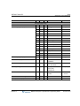
ADMIN PROGRAMMING
Station Data
Alarm (PGM 121 - FLEX12) … see details on page A-25
PGM 121
ALARM -- enable to receive system alarm signal.
BTN
RANGE
DEFAULT
12
1-3
1
System
Alarm (PGM 121 - FLEX12) … see details on page A-90
PGM 227
BTN
RANGE
DEFAULT
ALARM ENABLE -- enables the external contact monitoring circuitry.
1
0: Off
1: On
Off
ALARM CONTACT TYPE -- establishes the contact state that will
activate the Alarm, close or open.
2
0: Open
1:Close
Open
ALARM MODE -- the contact can be designated to function as a
doorbell instead of an alarm.
3
0: Bell
1: Alarm
Alarm
ALARM SIGNAL MODE -- the assigned stations will receive a
Repeating signal or single burst (ONCE) of the alarm tone.
4
0: Once
Repeat
1: Repeat
RELATED FEATURES
Door Open … see page 3-78
HARDWARE
Digital Phone
External contact connected to Alarm input of MPB, refer to MBX IP Hardware &
Installation Manual.
Release 1.0
MBX IP Description / Operations & Programming Guide
November 2010
Authorization Codes (Password)
3-5
Chapter 3: System Features
Authorization Codes (Password)
An Authorization Code is tied to a DN, and provides a means to control access to Walking COS,
or DISA and may be required for outgoing CO/IP Lines based on the configuration of the
database. When users dial a valid Authorization Code, the system invokes the Station COS.
The Station Authorization Code includes the associated station number and the assigned code.
A Station Authorization Code is specifically related to a given station and intended for a single
user.
The Administrator and Attendants are permitted to assign any Authorization code including
codes for another station. Normal users may only assign the Station Authorization code for the
specific station.
CONDITIONS
-
A user may enter an Authorization Code from any station to place a CO/IP call using
Walking COS.
-
An Authorization code may include any dial pad digit except
* and #.
OPERATION
Digital Phone
To assign a Station Authorization Code:
1. Press the [PGM] button.
2. Dial 34 {Authorization Code Program}.
3. Dial the Authorization Code (1-12 digits).
4. Dial
* or press the [SAVE] button to save.
Single Line Phone
To assign a Station Authorization code:
1. Lift the handset.
2. Dial [SLT Program Mode Entry code}.
3. Dial Station User Program code 34.
4. Dial Authorization Code (1-12 digits).
5. Dial .
*
Release 1.0
MBX IP Description / Operations & Programming Guide
November 2010
Auto Call Release
3-6
Chapter 3: System Features
System Attendant
To assign an Authorization Code:
1. Press the [PGM] button.
2. Dial Attendant Station Program Code 033.
3. Dial Station number for a Station code.
4. Dial the Authorization Code.
5. Press the [SAVE] button.
ADMIN PROGRAMMING
Station Data
Password (PGM 131 - FLEX 4) … see details on page A-33
PGM 131
BTN
RANGE
PASSWORD -- Password is employed to control access to the
system resources and facilities. Walking COS, CO/IP Group access
DISA callers and certain Call Forward types may require the input of
a valid password.
4
0: Disable
1: Enable
DEFAULT
Disable
Auto Call Release
Intercom calls (except Hands-free Ring Back) will be released automatically if the called party
does not answer during the pre-set time.
CONDITIONS
-
When the handset is used to place a call, the user will receive an error tone for 30
seconds followed by 30 seconds of Howler tone and the station is placed in a fault
mode. If on-hook dialing is used, the station will receive an error tone for one (1)
second and the phone will return to idle automatically.
OPERATION
System
Auto Call Release of Intercom calls: If a station places an intercom call and the called
station does not answer in the Intercom Call Release Time, the call is terminated and the
calling user receives an error tone.
Release 1.0
MBX IP Description / Operations & Programming Guide
November 2010
Automatic Pause Insertion
3-7
Chapter 3: System Features
ADMIN PROGRAMMING
Table Data
System Ring Table: Normal Call Ring … use Web Admin (PGM 265) see details on
page A-118
Howler Tone (PGM 121 - FLEX 7)… see details on page A-25
PGM 121
HOWLING TONE -- sets Anonymous Call Restrict service.
BTN
7
RANGE
0: Off
1: On
DEFAULT
On
Automatic Pause Insertion
In addition to a manually entered Pause, the system will automatically pause dialing to allow for
potential connection delays. The pause will be inserted when any of the following occur:
•
Flash is encountered in a Speed Dial number.
•
Pulse to Tone Switchover is encountered in a Speed Dial or Redial number.
•
Connect message is received on an ISDN Line.
CONDITIONS
-
An automatically inserted pause is not counted as a digit in a Speed Dial number.
-
The LCD of the Digital Phone will show a "P" when a pause is encountered.
-
When the System inserts a Pause, “P” indication is not shown.
OPERATION
System
The system automatically pauses dialing after an appropriate event (as listed above).
RELATED FEATURES
Auto Called Number Redial (ACNR) … see page 6-2
Last Number Redial (LNR) … see page 3-109
Dial Pulse to Tone Switchover … see page 3-62
Release 1.0
MBX IP Description / Operations & Programming Guide
November 2010
Automatic Privacy/Branch Line
3-8
Chapter 3: System Features
Automatic Privacy/Branch Line
Privacy is insured in all communications on the system. If desired, the customer may elect to
disable the Automatic Privacy feature, allowing an uninvited station to join in an existing
external conversation. In such a case, a conference is established. The Privacy feature
restricts the intrusion/call-wait/camp-on/OHVA at a busy station, while the Branch Line can
restrict a conference call by pressing {DN} button in use.
CONDITIONS
-
With Automatic Privacy disabled, privacy is still assured on all intercom and
conference calls.
-
Only one station can intrude on an active call.
-
An intrusion tone can be provided to the call indicating another station has accessed
the line.
OPERATION
Digital Phone
To intrude into a call when Privacy is disabled:
Make a call to busy station and then press the appropriate code for
intrusion/call-wait/camp-on/OHVA when receiving busy tone.
To change privacy mode in conversation:
Press the {DND} button during a conversation.
To intrude in a call when Branch Line is enabled:
Press a busy (lit steady) {DN} button, the user is connected to the call with the existing
internal station user.
ADMIN PROGRAMMING
Station Data
Branch Line (PGM 134 - FLEX 10) … see details on page A-36
PGM 134
BRANCH/BRIDGE LINE -- Set branch/bridge line feature.
Branch: Conference call by pressing {DN} button in use.
Bridge: Bridge call by pressing {DN} button in use.
Bridge (Softphone): Auto bridge if Phontage/UC Client’s IP bridge is
enabled.
Release 1.0
BTN
10
RANGE
DEFAULT
0: Off
1: On
Off
MBX IP Description / Operations & Programming Guide
November 2010
Automatic Privacy/Branch Line
3-9
Chapter 3: System Features
Auto Privacy (PGM 134 - FLEX 11) … see details on page A-36
PGM 134
BTN RANGE
AUTO PRIVACY -- Enables auto privacy feature (to restrict the
intrusion/call-wait/camp-on/OHVA in busy station)
11
0: Off
1: On
DEFAULT
Off
System Data
Intercom Busy One-Digit Service (PGM 237) … see details on page A-103
PGM 237
BTN
RANGE
0:Disable
1:Enable
DEFAULT
STEP CALL -- determines if Step Call is enabled or disabled.
1
Disable
DIGIT 1 -- when accessing a busy tone, user may dial for one of
the one-touch services.
2
DIGIT 2 --
3
DIGIT 3 --
4
DIGIT 4 --
5
DIGIT 5 --
6
DIGIT 6 --
7
DIGIT 7 --
8
DIGIT 8 --
9
DIGIT 9 --
10
DIGIT 0 --
11
DIGIT * --
12
Call Wait
DIGIT # --
13
Voice-Over
0: N/A
0: N/A
1: Call-Back
2: Camp On
3: Call Wait
4: Voice Over
5: Intrusion
6: Hunt
RELATED FEATURES
Multi-Party Voice Conference … see page 3-50
Station Flexible Buttons … see page 6-21
Release 1.0
MBX IP Description / Operations & Programming Guide
November 2010
Auto Service Mode Control
3-10
Chapter 3: System Features
Auto Service Mode Control
The service mode defines different ring assignments, COS and answering privileges for the
system. The service mode can be controlled automatically through definitions in the Auto Ring
Mode Selection Table, which defines the time of day for Day, Night and Timed shift modes. The
Attendant may change the system mode selection from automatic to manual.
CONDITIONS
-
If the system has Holiday information and current mode is Holiday, service mode is
operated as Night mode
OPERATION
System
Operation of this feature is automatic.
ADMIN PROGRAMMING
Table Data
System Time Table (PGM 253) … see details on page A-110
PGM 253
Release 1.0
BTN
RANGE
DEFAULT
TIME ZONE COMMENT-- defines the comment of the Time
Table.
1
32 characters none
SYSTEM TIME ZONE -- defines the Time Zone of the Time Table
2
0-73
0: Sys Time
DAYLIGHT SAVINGS -- defines Daylight Saving Time of Time
Table.
3
On/Off
Off
RING MODE -- defines the ring mode of Time Table.
4
0: Day
1: Night
2: Timed
0: Day
AUTO RING MODE -- defines the Auto Ring mode of the Time
Table.
5
On/Off
Off
MBX IP Description / Operations & Programming Guide
November 2010
Auto Service Mode Control
3-11
Chapter 3: System Features
Weekly Time Table (PGM 254) … see details on page A-111
PGM 254
BTN
RANGE
DEFAULT
Monday DAY/NIGHT/TIMED ring mode start times and TIMED mode
end times.
1
0000-2359
Day: 9:00
Nite: 18:00
TDS: _-_
TDE: _-_
Tuesday DAY/NIGHT/TIMED ring mode start times and TIMED
mode end times.
2
0000-2359
Day: 9:00
Nite: 18:00
TDS: _-_
TDE: _-_
Wednesday DAY/NIGHT/TIMED ring mode start times and TIMED
mode end times.
3
0000-2359
Day: 9:00
Nite: 18:00
TDS: _-_
TDE: _-_
Thursday DAY/NIGHT/TIMED ring mode start times and TIMED
mode end times.
4
0000-2359
Day: 9:00
Nite: 18:00
TDS: _-_
TDE: _-_
Friday DAY/NIGHT/TIMED ring mode start times and TIMED mode
end times.
5
0000-2359
Day: 9:00
Nite: 18:00
TDS: _-_
TDE: _-_
Saturday DAY/NIGHT/TIMED ring mode start times and TIMED
mode end times.
6
0000-2359
Day: 9:00
Nite: 18:00
TDS: _-_
TDE: _-_
Sunday DAY/NIGHT/TIMED ring mode start times and TIMED mode
end times.
7
0000-2359
Day: 9:00
Nite: 18:00
TDS: _-_
TDE: _-_
Holiday Time Table (PGM 256) … see details on page A-113
Release 1.0
PGM 256
BTN
RANGE
DEFAULT
CALENDAR TYPE -- Defines Calendar Type for Holiday Table.
1
Lunar/Gregorian
Gregorian
HOLIDAY DATE -- Defines Holiday Date for Holiday Table.
2
MM/DD
None
MBX IP Description / Operations & Programming Guide
November 2010
Automatic System Daylight Savings Time
3-12
Chapter 3: System Features
RELATED FEATURES
Direct Inward System Access (DISA) … see page 5-51
Day/Night/Timed Ring Mode … see page 7-37
CO Ring Assignment … see page 5-38
LBC (Loud Bell Control) … see page 3-115
Dialing Restrictions … see page 3-63
Automatic System Daylight Savings Time
The system can automatically adjust for Daylight Saving Time (DST). When DST is enabled,
the system will adjust the system time forward one hour at the DST Start time and back one
hour at the DST End time. The system time is sent for display to all devices and terminals and
is the basis of the various system time-based features (Wake-up Alarm, etc.).
CONDITIONS
-
The DST Start and End times are set by the Web Admin interface only.
-
The interval between the DST Start and End times must be at least 7 days.
OPERATION
System
Operation of this feature is automatic.
ADMIN PROGRAMMING
System
System Time (PGM 233 - FLEX 1) … see details on page A-97
PGM 233
SYSTEM TIME/DATE -- sets the system time.
BTN
1
RANGE
HH:MM
DEFAULT
-
System Date (PGM 233 - FLEX 2) … see details on page A-97
PGM 233
SYSTEM TIME/DATE -- sets the system date.
Release 1.0
BTN
2
RANGE
MMDDYY
DEFAULT
-
MBX IP Description / Operations & Programming Guide
November 2010
Automatic System Time Synchronization
3-13
Chapter 3: System Features
DST Enable (PGM 233 - FLEX 3) … see details on page A-97
DST Start & End Time … use Web Admin (PGM 233)
PGM 233
BTN
RANGE
DEFAULT
DST START TIME -- the DST start time.
Web See DST Table 2nd Sunday of March
Only
at 2:00 AM
DST END TIME -- the DST end time.
Web See DST Table 1st Sunday of
Only
November at 2:00 AM
RELATED FEATURES
Auto Service Mode Control … see page 3-10
Automatic System Time Synchronization … see page 3-13
System Clock Set … see page 7-42
Automatic System Time Synchronization
When enabled, the system automatically determines and sets the time of day employing
Network Time Protocol (NTP) or ISDN time messages. When using NTP, the system requests
and receives GMT time at ten-minute intervals from the specified NTP time server. This feature
allows the System Time to synchronize with the NTP time server automatically. If the time
deviates more than two seconds, the system clock is adjusted to match the NTP server.
When using ISDN, the system receives the time of day in ISDN messages and automatically
adjusts the time if the system time deviates from the ISDN time.
CONDITIONS
-
NTP packets are expected over UDP port 123; verify the port is open and available.
-
A secondary NTP server address can be defined should the first server not respond.
-
If set, the system adjusts for the local time zone assigned in the system as the
Standard System Time as well as Daylight Savings Time (DST).
OPERATION
System
Operation of this feature is automatic.
Release 1.0
MBX IP Description / Operations & Programming Guide
November 2010
Battery Back-up, Memory
3-14
Chapter 3: System Features
ADMIN PROGRAMMING
System
Network Time/Date (PGM 223 – FLEX 5) … see details on page A-88
PGM 223
BTN
NETWORK DATE/TIME USE -- If set to ON, the System updates the
Date & Time with Network Date & Time when the System Date &
Time is different.
5
RANGE
0: Off
1: On
DEFAULT
0: Off
NTP Active … use Web Admin (PGM 233)
NTP Sever Address … use Web Admin (PGM 233)
Standard System Time, Local Time Zone … use Web Admin (PGM 233)
RELATED FEATURES
Auto Service Mode Control … see page 3-10
Automatic System Daylight Savings Time … see page 3-12
System Clock Set … see page 7-42
Battery Back-up, Memory
The system database is protected from power-loss by a long life (10-year) lithium dry cell
battery. Should local power fail, the battery will maintain the system memory and proper
operation of the system clock.
CONDITIONS
-
The Initialization switch must be in the ON position to enable Memory Battery
Back-up. Otherwise, should power fail, the system will initialize the database on
power-up. Refer to the MBX IP Hardware and Installation Guide for more details.
-
The Lithium battery is not field-replaceable.
OPERATION
System
When enabled, operation is automatic.
Release 1.0
MBX IP Description / Operations & Programming Guide
November 2010
Call Forward
3-15
Chapter 3: System Features
Call Forward
User may have selected incoming calls re-route to other stations (local or networked), station
groups, the VMIIB, or over a system CO/IP line (Off-Net).
The user selects the type and condition under which calls will forward by entering a Call
Forward code as follows:
•
Code 0, Remote Call Forward – forwards all calls to the station, except recalls,
activated from a remote station, Call Forward, Follow-me.
•
Code 1, Unconditional – all calls to the station, except recalls, are forwarded internally
or externally immediately upon receipt.
•
Code 2, Busy – if the station is busy, forwards all calls, except recalls, to the selected
station.
•
Code 3, No Answer – forwards all calls, except recalls, to the selected station when
the station does not answer within the No Answer timer.
•
Code 4, Busy/No Answer – forwards calls if the selected station is busy or does not
answer within the No Answer timer.
CONDITIONS
Release 1.0
-
A station receiving a forwarded call can transfer the call to the forwarding station.
-
A station, denied the use of Call Forward, will receive an error tone in response to
attempts to activate Call Forward.
-
A forwarded intercom call will signal the receiving station in Tone Signaling mode,
regardless of the Intercom Signaling Mode at the station.
-
Attempting activation of Call Forward will automatically deactivate any activated
Display Text Message (Active Call Back or Queue requests do not cancel).
-
When Call Forward is active, a Station can make outgoing calls (internal or external).
-
For CO/IP calls, when Call Forward is manually activated, it will override any Preset
Call Forward assigned for the station or CO/IP line
-
Call Forward status is maintained in the System’s non-volatile memory for protection
from power outage.
-
Off-Net Call Forward of incoming CO/IP calls is essentially an automated DISA call,
which will establish an Unsupervised Conference; such calls are subject to the
conditions of a DISA call and Unsupervised Conference and may require entry of an
Authorization Code.
-
Off-Net Forward calls are not answered until the system completes dialing of the
external call. The call, internal or external, is then connected to the Off-Premise call.
MBX IP Description / Operations & Programming Guide
November 2010
Call Forward
3-16
Chapter 3: System Features
-
An unlimited number of stations may be set-up in a Call Forward chain, forwarding
calls from one station to the next. However, the Call Forward service counter is
restricted by the ‘Multi-Call Forward Service Count’ attribute (tenant based).
-
No Answer Forward employs the Station No Answer Forward Timer.
-
The No Answer Call Forward Timer can be adjusted at the PGM 141, FLEX 4.
-
A Station should have Off-Net Forward access privilege to assign a CO Access code
and External Phone number to the forward destination.
OPERATION
Digital Phone
To activate Call Forward, Unconditional or Busy/No Answer:
1. Lift the handset or press the [SPEAKER] button to receive a dial tone.
2. Press the [FWD] button.
3. Dial 1-4 {Forward Code} as appropriate.
4. Dial the station or station group to receive calls.
OR
5. Dial CO Group Access code and desired external phone number.
6. Press the [SAVE] button to save.
7. Replace the handset, return to idle.
To activate Call Forward, Remote (Follow-me):
1. Lift the handset or press [SPEAKER] button to receive Dial tone.
2. Press the [FWD] button.
3. Dial 0 {Call Forward code}.
4. Dial the Station’s Authorization Code (Station number + password),
5. Dial 1-4 {Forward condition}.
6. Dial the destination station or station group. OR Dial CO Group Access code and
desired external phone number.
7. Press [SAVE] button to save.
8. Replace the handset, return to idle.
To deactivate Call Forward:
Press flashing [FWD] button, Call Forward will deactivate; [FWD] LED button is turned
OFF.
Release 1.0
MBX IP Description / Operations & Programming Guide
November 2010
Call Forward
3-17
Chapter 3: System Features
Single Line Phone
To activate Call Forward, Unconditional, Busy/No-Answer:
1. Lift the handset to receive Dial tone.
2. Dial {Call Forward feature code}
3. Dial 1-4 (Call Forward code) as desired.
4. Dial station or station group to receive calls. OR Dial the CO Group Access code and
the desired external phone number.
5. Press hook-switch to save.
6. Replace the handset, return to idle.
To activate Call Forward, Remote (Follow-me):
1. Lift the handset.
2. Dial {Call Forward code}.
3. Dial 0 {Remote Forward code}.
4. Enter the Station number {Station Authorization Code} +Password.
5. Dial 0 {Remote Forward condition}.
6. Dial the destination station or station group.
OR
Dial CO Group Access code and desired external phone number.
7. Press hook-switch to save.
8. Replace handset return to idle.
To deactivate the Call forward
1. Lift the handset to receive a stutter Dial tone.
2. Dial {Call Forward feature code}, as desired.
3. Dial ‘#’ to cancel Call Forward.
Release 1.0
MBX IP Description / Operations & Programming Guide
November 2010
Call Forward
3-18
Chapter 3: System Features
ADMIN PROGRAMMING
Station Data
Call Forward Access (PGM 132 FLEX 2) … see details on page A-34
PGM 132
BTN
RANGE
CALL FORWARD ACCESS -- enables Call Forward to be activated
by the station.
2
0: Disable
1: Enable
DEFAULT
Enable
OffNet Call Forward Access (PGM 132 FLEX 3) … see details on page A-34
PGM 132
BTN
RANGE
OFFNET CALL FORWARD ACCESS -- a station must be allowed Off
Net Fwd to forward external incoming calls outside the system or
otherwise establish a CO-to-CO connection.
3
0: Disable
1: Enable
DEFAULT
Enable
Call Forward Assignment (PGM 143) … see details on page A-42
PGM 143
Release 1.0
BTN
RANGE
DEFAULT
FORWARD TYPE -- specify call forward type.
1
Not Assigned
0: Not Assigned
1: Unconditional
2: Busy
3: No Answer
4: Busy or No Answer
FORWARD NUMBER -- specify Call Forward
Destination by entering dial digits.
2
Max 32 digits
-
FORWARD APPLY TIME -- specify Call Forward
Applying Time.
3
0: All
1: Day
2: Night
3: Timed
All
CALL FORWARD NO ANSWER TIMER -- if the station
does not respond during the ‘CFW NO ANS TMR’ timer,
the call is forwarded to Call Forward Destination.
4
( 0-600) sec
15 sec
FORWARD DISPLAY -- enables the Forward Display
Option to check forward information in idle state.
5
0: Off
1: On
On
MBX IP Description / Operations & Programming Guide
November 2010
Call Forward, Pilot Hunt
3-19
Chapter 3: System Features
Tenant Data
Multi-Call Forward Service Center … see page A-131
PGM 280
MULTI-CALL FORWARD SERVICE COUNTER -- determines the
Multi-Call forward count.
BTN
8
RANGE
01-10
DEFAULT
05
RELATED FEATURES
Station Authorization Code … see page 3-5
DND … see page 3-76
Dialing Restriction … see page 3-63
Station Group … see page 3-150
Intercom Signaling Mode … see page 6-11
Call Forward, Preset … see page 3-22
Call Forward, Pilot Hunt
User may have selected incoming calls in his group to re-route to other stations (local or
networked), station groups, or VMIIB. The user selects the type and condition under which calls
will forward by entering a Call Forward code as follows:
Code 1, Unconditional – all calls to the station, except recalls, are forwarded internally or
externally immediately upon receipt.
Code 2, Busy – if the station is busy, forwards all calls, except recalls, to the selected
station.
Code 3, No Answer – forwards all calls, except recalls, to the selected station when the
station does not answer within the No Answer timer.
Code 4, Busy/No Answer – forwards calls if the selected station is busy or does not
answer within the No Answer timer.
CONDITIONS
Release 1.0
-
Station Call Forward has higher priority than Pilot Hunt Call Forward.
-
To assign Pilot Hunt Call forward, the Station should be a member of the Pilot Hunt
Group.
-
An external number cannot be assigned to a Pilot Hunt Forward destination.
-
If a station assigns the pilot hunt Call Forward, the pilot hunt call forward in day mode
is changed.
MBX IP Description / Operations & Programming Guide
November 2010
Call Forward, Pilot Hunt
3-20
Chapter 3: System Features
-
The Pilot Hunt Ring access privilege can be assigned on a per Station basis; if the
Pilot Hunt Ring access of the station is disabled, that station will not receive Pilot Hunt
ringing.
-
If a user activates the call forward feature using the {Pilot Hunt Call Forward code}, it
is applied to the Day Forward destination.
OPERATION
Digital & Single Line Phone
To activate Call Forward, Unconditional or Busy/No Answer:
1. Lift the handset or press the [SPEAKER] button to receive dial tone.
2. Dial {Pilot Hunt Call Forward Code}
3. Dial 1-4 {Call Forward code} as desired.
4. Dial the station or station group to receive calls.
5. Press the [SAVE] button to save.
6. Replace the handset, return to idle.
To deactivate the Call Forward:
1. Lift the handset or press the [SPEAKER] button,
2. Dial {Pilot Hunt Call Forward Cancel Code},
ADMIN PROGRAMMING
Station Data
Call Forward Access (PGM 132 - FLEX 2) … see details on page A-34
PGM 132
BTN
RANGE
CALL FORWARD ACCESS -- enables Call Forward to be activated
by the station.
2
0: Disable
1: Enable
DEFAULT
Enable
Pilot Hunt Ring Access (PGM 134 - FLEX 6) … see details on page A-34
PGM 134
PILOT HUNT RING -- permits station to receive pilot hunt ring.
Release 1.0
BTN
RANGE
6
0:Disable
1:Enable
MBX IP Description / Operations & Programming Guide
DEFAULT
Enable
November 2010
Call Forward, Pilot Hunt
3-21
Chapter 3: System Features
Station Group Data
Pilot Hunt Group (PGM 210 - 211) … see details on page A-77
PGM 210
Release 1.0
BTN
RANGE
DEFAULT
CONDITION -- Determines call coverage condition for Pilot Hunt
group.
1
All
0: ALL
1: Intercom
2: External
SERVICE TYPE -- This entry defines Service Type.
(Terminal/Circular)
2
0: Terminal
1: Circular
Terminal
TIME TABLE INDEX -- Time Table index.
3
1-9
1
MEMBER ASG --Assigns stations as members of a Pilot Hunt group.
4
-
-
PGM 211
BTN
RANGE
DAY FORWARD TYPE -- determines Day time seting for Call
Forward type.
1
Not Used
0: Not Used
1: Uncond
2: Busy
3: No Ans
4: Busy/ No Ans
DAY FORWARD DESTINATION -- determines Day time seting
for Forward destination.
2
Max. 8 digits
NIGHT FORWARD TYPE -- determines the Night time seting
for Call Forward type.
3
Not Used
0: Not Used
1: Uncond
2: Busy
3: No Ans
4: Busy/ No Ans
NIGHT FORWARD DESTINATION -- determines the Night
time seting for Forward destination.
4
Max. 8 digits
TIMED FORWARD TYPE -- determines the Timed seting for
Forward type.
5
Not Used
0: Not Used
1: Uncond
2: Busy
3: No Ans
4: Busy/ No Ans
TIMED FWD DESTINATION -- determines the Timed seting for
Forward destination.
6
Max. 8 digits
MBX IP Description / Operations & Programming Guide
DEFAULT
-
-
-
November 2010
Call Forward, Preset
3-22
Chapter 3: System Features
RELATED FEATURES
Station Authorization Code … see page 3-5
DND … see page 3-76
Dialing Restriction … see page 3-63
Station Group … see page 3-150
Intercom Signaling Mode … see page 6-11
Call Forward, Preset … see page 3-22
Call Forward, Preset
Call Forward, Preset calls to a Station are forwarded to a pre-determined destination assigned
in the system database. Preset Call Forward can define separate treatment of CO/IP calls and
intercom calls. In addition, separate busy and no-answer treatments are defined:
•
Internal Unconditional – all intercom calls are immediately forwarded.
•
Internal Busy – Intercom calls that encounter a busy, are forwarded immediately.
•
Internal No-Answer – Intercom calls, which are not answered in the No-Answer time,
or busy, are forwarded.
•
External Unconditional – all external calls immediately forward.
•
External Busy – external calls that encounter a busy are forwarded immediately.
•
External No-Answer – external calls, not answered in the No-Answer time, or busy,
are forwarded.
In addition, calls can be directly forwarded to the Users Voice Mail box using Call Forward,
Preset. Preset Call Forward condition and type can be selected as listed:
•
Unconditional – all calls to the station, are forwarded internally or externally
immediately upon receipt.
•
Busy – if the station is busy, all calls are forwarded to the selected station.
•
No Answer - forwards all calls to the selected station when the station does not
answer within the No Answer timer.
CONDITIONS
Release 1.0
-
A station receiving a forwarded call can transfer the call to the forwarding station.
-
Calls cannot be forwarded to a station in DND (error tone is returned).
-
Manual forward has a higher priority than Preset Forward and overrides any Preset
Forward setting.
-
Preset call forward status is not shown on the Station LCD display.
MBX IP Description / Operations & Programming Guide
November 2010
Call Forward, Preset
3-23
Chapter 3: System Features
-
No Answer Forward employs the Station No Answer Forward timer.
-
If Station No Answer Preset Call Forward and CO Preset Forward Ring Table is set
the same, the CO Preset Forward Ring Table precedes Station Preset Call Forward.
OPERATION
System
When enabled, operation of Preset Call Forward is automatic.
ADMIN PROGRAMMING
Station Data
Preset Call Forward (PGM 142) … see details on page A-41
PGM 142
BTN
RANGE
DEFAULT
INTERNAL UNCOND -- The unconditional preset forward
destination of internal(intercom) call .
1
Max 32 digits
-
INTERNAL BUSY -- The busy preset forward destination of
internal(intercom) call.
2
Max 32 digits
-
INTERNAL NO-ANSWER -- The no-answer preset forward
destination of internal(intercom) .
3
Max 32 digits
-
EXTERNAL UNCOND -- The unconditional preset forward
destination of external call.
4
Max 32 digits
-
EXTERNAL BUSY -- The busy preset forward destination of
external call.
5
Max 32 digits
-
EXTERNAL NO-ANSWER -- The no-answer preset forward
destination of external call.
6
Max 32 digits
-
Call Forward No-Answer Timer (PGM 143 - FLEX 4) … see details on page A-42
Release 1.0
PGM 143
BTN
CFW NO ANS TMR -- Busy or No Answer - employs this 'CFW NO
ANS TMR' timer. If the station does not respond during the 'CFW
NO ANS TMR' timer. Call is forwarded to 'Call Forward
Destination'.
4
RANGE
0-600 secs
MBX IP Description / Operations & Programming Guide
DEFAULT
15 secs
November 2010
Call Park
3-24
Chapter 3: System Features
RELATED FEATURES
Call Forward… see page 3-15
DND … see page 3-76
Auto Attendant … see page 3-86
Preset Call Forward … see page 3-22
VMIB Integrated Auto Attd/Voice Mail … see page 3-254
Call Park
A User may place (Park) an active intercom or CO/IP call in a special holding location (Park
Orbit) for easy access from any station in the system. The system has 50 holding locations
(Park Orbits).
CONDITIONS
-
If the selected Park Orbit returns a busy signal, the user may simply dial another Park
Orbit without disconnecting.
-
A Parked call will recall to the station that parked the call should the Call Park Timer
expire. The normal Hold Recall process is then initiated.
-
A Parked call will indicate busy at all appearances.
OPERATION
Digital Phone
To park an active external call:
1. Press the [TRANS] button.
2. Dial {Call Park Feature Code}.
3. Dial the Call Park No (00-49).
4. Return to idle.
To retrieve a parked call:
1. Lift the handset or press the [SPEAKER] button.
2. Dial {Call Park Feature Code}.
3. Dial the Call Park No (00-49).
Release 1.0
MBX IP Description / Operations & Programming Guide
November 2010
Call Park
3-25
Chapter 3: System Features
Single Line Phone
To park an active external call
1. Press the hook-switch.
2. Dial {Call Park Feature Code}.
3. Dial the Call Park No (00-49).
4. Return to idle.
To retrieve a parked call
1. Lift the handset.
2. Dial {Call Park Feature Code}
3. Dial the Call Park No (00-49).
ADMIN PROGRAMMING
Numbering Data
Call Park Code (PGM 113) … see details on page A-19
BTN
36
FEATURE (PGM 113)
Call Parking Location
REMARK
541 + xx (Parking Location 00-49)
Tenant Data
Call Park Hold Tone Time … see page A-138_use Web Admin (PGM 290 - FLEX 58-59)
PGM 290
TONE TIME -- Determines the amount of time tone is provided.
BTN
2
RANGE
1-600
DEFAULT
10
RELATED FEATURES
Hold … see page 3-100
Hold Recall … see page 3-101
Release 1.0
MBX IP Description / Operations & Programming Guide
November 2010
Call Pick-Up
3-26
Chapter 3: System Features
Call Pick-Up
Directed Call Pick-Up
A station may answer (Pick-Up) incoming and transferred intercom, CO and IP calls ringing at
another station. All ringing calls are subject to Directed Call Pick-up except queued Callbacks.
Digital phone users may assign a Flex button as a {DIRECTED CALL PICK-UP} button.
CONDITIONS
-
To pick-up a CO/IP call, the station must have an idle appearance button.
-
When several calls are ringing at a station simultaneously, Call Pick-up will connect
the first call received.
-
Queue callback calls are not subject to Call Pick-up (receives an error tone).
-
Only ringing intercom calls are subject to Call Pick-up; Intercom calls announced
hands free cannot be picked up by another station.
OPERATION
Digital Phone
To assign a {directed call pick-up} button:
Press [PGM] + {Flex} + Button Feature Type (1) + {Direct Pickup Feature Code} + [SAVE].
To Pick-up a call ringing at another station:
1. Lift the handset or press [SPEAKER].
2. Dial {Directed Call Pick-up code}.
3. Dial the intercom number of the ringing station.
OR
1. Lift the handset or press [SPEAKER].
2. Press the {DIRECTED CALL PICK-UP} button.
3. Dial the intercom number of the ringing station.
Single Line Phone
To Pick-up a call ringing at another station:
1. Lift the handset
2. Dial {Directed Call Pick-up code}.
3. Dial the number of the ringing station.
Release 1.0
MBX IP Description / Operations & Programming Guide
November 2010
Call Pick-Up
3-27
Chapter 3: System Features
ADMIN PROGRAMMING
Numbering Data
Feature Numbering Plan (PGM 113) … see details on page A-18
Station Group Data
Station Data -- Pickup by DSS (PGM 124 - FLEX 9) … see details on page A-28
PGM 124
PICKUP BY DSS BUTTON -- this value determines the
method of pickup when pressing DSS button.
BTN
RANGE
DEFAULT
9
0: Disable
1: Group Pickup
2: Direct Pickup
Direct Pickup
Station Group Attributes, Pick-up Option (PGM 200 - FLEX 5) … see details on page A-67
PGM 200
BTN
PICKUP OPTION -- stations can pickup group calls ringing at
other stations in the group.
RANGE
5
0: Disable
1: All Call
2: Intercom
3: External
DEFAULT
Disable
Call Pick-up Group Attributes (PGM 204) … see details on page A-73
PGM 204
BTN
RANGE
DEFAULT
PICK UP CONDITION -- this entry defines pick up condition.
(All/Internal/External)
1
0: All Call
1: Int Call
2: Ext Call
All Call
PICK UP MEMBER ASG -- assigns stations as members of a station
pickup group.
2
-
-
RELATED FEATURES
Intercom Signaling Mode … see page 6-11
Group Call Pick-up … see page 3-28
Release 1.0
MBX IP Description / Operations & Programming Guide
November 2010
Call Pick-Up
3-28
Chapter 3: System Features
Group Call Pick-Up
A Station can answer (Pick-Up) incoming and transferred intercom, CO and IP calls ringing at
another station in the same station group. All ringing calls, except Private Queue Callbacks, are
subject to Pick-up by other stations in the same group. Digital phone users may assign a Flex
button as a {GROUP CALL PICK-UP} button.
CONDITIONS
-
To pick-up a CO/IP call, the station must have an idle appearance button.
-
When several calls are ringing at a station simultaneously, Call Pick-up will connect
the first call received.
-
Queue callback calls are not subject to Call Pick-up (receives error tone).
-
Only ringing intercom calls are subject to Call Pick-up; Hands free announced
intercom calls cannot be picked up by another station.
-
When a station belongs to multiple groups, calls received are routed to the group with
the lowest station number.
OPERATION
Digital Phone
To assign a {GROUP CALL PICK-UP} button:
PRESS [PGM] + {FLEX} + Button Feature Type(1) + {Group Pickup Feature Code} +
[SAVE]
To Pick-up a call ringing at another station:
1. Lift the handset or press [SPEAKER].
2. Dial {Group Call Pick-up code}.
OR
3. Press the programmed Group Call Pick-up button.
Single Line Phone
To Pick-up a call ringing at another station:
1. Lift the handset.
2. Dial {Group Call Pick-up code}.
Release 1.0
MBX IP Description / Operations & Programming Guide
November 2010
Call Pick-Up
3-29
Chapter 3: System Features
ADMIN PROGRAMMING
Numbering Data
Feature Numbering Plan (PGM 113) … see details on page A-18
Station Group Data
Station Group Attributes, Pick-up Option (PGM 200 - FLEX 5) … see details on page A-67
PGM 200
PICKUP OPTION -- stations can pickup group calls ringing at
other stations in the group.
BTN
RANGE
5
0: Disable
1: All Call
2: Intercom
3: External
DEFAULT
Disable
Call Pick-up Group Attributes (PGM 204) … see details on page A-73
PGM 204
PICK UP CONDITION -- this entry defines pick up condition.
(All/Internal/External)
PICK UP MEMBER ASG -- assigns stations as members of a station
pickup group.
BTN
RANGE
1
0: All Call
1: Int Call
2: Ext Call
2
-
DEFAULT
All Call
-
RELATED FEATURES
Intercom Signaling Mode … see page 6-11
Group Call Pick-up … see page 3-28
Station Group … see page 3-150
Release 1.0
MBX IP Description / Operations & Programming Guide
November 2010
Call Transfer
3-30
Chapter 3: System Features
Call Transfer
Call Transfer, Station
CO/IP calls can be transferred to other stations on the same System. Calls can be transferred
without announcing the call (unscreened), or with announcement (screened).
When a call is transferred, the Transfer Recall Timer is initiated. If the timer expires before the
call is answered, the Hold Recall process is initiated.
CONDITIONS
-
The transferring station may camp on a call on to a busy station.
-
To prevent Toll abuse, CO/IP lines without an active call (either incoming or dialed
digits on outgoing) cannot be transferred.
-
For outgoing CO Line calls, the system will monitor the CO Line for dial tone to
prevent Toll abuse; when an IP Line is seized, the system does not monitor for dial
tone.
OPERATION
Digital Phone
While on a CO/IP call, to perform a Screened Call Transfer:
1. Press [TRANS].
2. Dial the station to receive the transfer.
3. At answer or splash tone, announce the call.
4. Hang-up to complete the transfer.
OR
5. Press the {DSS/BLF} button for the desired station.
6. When answered or when splash tone is heard, announce the call.
7. Hang-up to complete the transfer.
While on a CO/IP call, to perform an Unscreened Call Transfer:
1. Press [TRANS].
2. Dial the station to receive the transfer.
3. Hang-up to complete the transfer.
OR
4. Press the {DSS/BLF} button for the desired station.
5. Hang-up to complete the transfer.
Release 1.0
MBX IP Description / Operations & Programming Guide
November 2010
Call Transfer
3-31
Chapter 3: System Features
Single Line Phone
While on a CO/IP call, to perform a Screened Call Transfer:
1. Press for hook-switch.
2. Dial the station to receive the transfer.
3. When answered or when splash tone is heard, announce the call.
4. Hang-up to complete the transfer.
While on a CO/IP call, to perform an Unscreened Call Transfer:
1. Press for hook-switch.
2. Dial the station to receive the transfer.
3. Hang-up to complete the transfer.
RELATED FEATURES
Hold Recall … see page 3-101
Call Transfer, CO/IP … see page 3-31
Station Flexible Buttons … see page 6-21
Call Transfer, CO/IP
A Station may be permitted to transfer a CO/IP call to another CO/IP line, establishing an
Unsupervised Conference between the two external parties.
If the receiving party is called through an ISDN or VoIP path, the Transfer Hold Recall Timer is
initiated and if it expires, Hold Recall is initiated.
CONDITIONS
Release 1.0
-
A call using the service of 2 CO lines and not providing call disconnection detection
will be disconnected following the expiration of the Unsupervised Conference timer.
-
The system provides Transfer Recall on ISDN and VoIP calls providing ‘Answer
Supervision’.
-
If during a transfer to an external party, the user presses the CO/IP line of the original
call, the outgoing call is disconnected and the original call is connected to the user.
-
The CO-to-CO transfer can be enabled or disabled by using the Transit Option on CO
line basis and also by using offnet forward option on station basis..
-
If the transferred call is not answered by the destination Station, the call is routed to
the ‘Transfer No Answer Destination’ of the CO Alternative Destination.
-
When CO 1 is transferred to CO 2, if the CO 2 does not answer within the CO-to-CO
transfer recall timer, both CO lines are disconnected.
MBX IP Description / Operations & Programming Guide
November 2010
Call Transfer
3-32
Chapter 3: System Features
OPERATION
Digital Phone
While on a CO/IP call, to perform a Screened Call Transfer:
1. Press [TRANS].
2. Place a CO/IP call in the normal manner.
3. When answered, announce the call.
4. Hang-up to complete the transfer.
While on a CO/IP call, to perform an Unscreened Call Transfer:
1. Press [TRANS].
2. Place CO/IP call in the normal manner.
3. Hang-up to complete the transfer.
Single Line Phone
While on a CO/IP call, to perform a Screened Call Transfer:
1. Press for hook-switch.
2. Place CO/IP call in the normal manner.
3. When answered, announce the call.
4. Hang-up to complete the transfer.
While on a CO/IP call, to perform an Unscreened Call Transfer:
1. Press for hook-switch.
2. Place CO/IP call in the normal manner.
3. Hang-up to complete the transfer.
ADMIN PROGRAMMING
Station Number Data
Offnet Forward Access (PGM 132, FLEX 3) … see details on page A-34
PGM 132
BTN
RANGE
OFFNET FORWARD ACCESS -- a station must be allowed Off Net
Fwd to forward external incoming calls outside the system or
otherwise establish a CO-to-CO connection.
3
0: Disable
1: Enable
Release 1.0
MBX IP Description / Operations & Programming Guide
DEFAULT
Enable
November 2010
Call Transfer
3-33
Chapter 3: System Features
CO Line Data
CO-to-CO Attributes (PGM 179) … see details on page A-63
PGM 179
BTN
STATION OUTGOING CALL TRANSFER -- while stations are
connected to outgoing CO call of first CO Group, the station
can transfer the call to second CO group.
1
0: Off
1: On
On
OUTGOING CALL TRANSFER -- while ATD is connected to
outgoing CO call of first CO Group, the ATD can transfer the
call to second CO group.
2
0: Off
1: On
On
OUTGOING CALL TRANSFER RELEASE TYPE -- if outgoing
CO call can be transferred to other CO call, release type can
be set. If set to None, it is not disconnected.
3
0: None
1: Release after
Release Timer
None
OUTGOING CALL TRANSFER RELEASE TIME -- if an
outgoing CO call is transferred to CO call and CO - to - CO call
is started, the call is disconnected after release time, when
release type is set to 'Rls after Rls Time'. Before disconnecting,
a warning tone is provided.
4
000-300 (sec)
060
INCOMING CALL TRANSFER DIRECTLY -- if this feature
5
0: Off
1: On
Off
STATION INCOMING CALL TRANSFER -- while stations
are connected to incoming CO call of first CO Group, the
station can transfer the call to second CO group.
6
0: Off
1: On
On
ATD INCOMING CALL TRANSFER -- while ATD is
connected to incoming CO call of first CO Group, the ATD can
transfer the call to second CO group.
7
0: Off
1: On
On
INCOMING CALL TRANSFER RELEASE TYPE -- If incoming
CO call can be transferred to other CO call, release type can
be set. If set to None, it is not disconnected.
8
0: None
1: Release after
Release Timer
None
INCOMING CALL TRANSFER RELEASE TIME -- If an
incoming CO call is transferred to CO call and CO - to - CO call
is started, the call is disconnected after release time, when
release type is set to 'Rls after Rls Time'. Before disconnected,
warning tone is provided.
9
000-300 (sec)
060
is set to ON, CO incoming call can be transferred directly
without any stations or ATD to transfer the call.
Release 1.0
RANGE
MBX IP Description / Operations & Programming Guide
DEFAULT
November 2010
Call Transfer
3-34
Chapter 3: System Features
Unsupervised Conference Extend (PGM 166) … see details on page A-52
PGM 166
BTN
RANGE
UNSUP CONF ENTEND -- If this feature is set to ON, unsupervised
conference timer can be extended by dial feature code after warning
tone is heard.
3
0: Disable
1: Enable
DEFAULT
Disable
Unsupervised Conference Extend (PGM 171) … see details on page A-59
PGM 171
BTN
UNSUP CONF EXTEND -- If this feature is set to ON, Unsupervised
Conf Timer can be extended by dialing feature code after warning
tone is heard.
2
RANGE
0: Off
1: On
DEFAULT
Off
Unsupervised Conference Timer (PGM 166) … see details on page A-52
PGM 166
UNSUP CONF TIMER -- When there is conference call without
supervisor, or there is any CO-to-CO call, the call is disconnected
after timer expires. The warning tone is heard before the line is
disconnected.
BTN
9
RANGE
000-255
(min)
DEFAULT
000
Unsupervised Conference Timer (PGM 171) … see details on page A-59
PGM 171
UNSUP CONF TIMER -- When there is conference call without
supervisor, or there is any CO-to-CO call, the call is disconnected
after the timer expires. The warning tone is heard before the line is
disconnected.
Release 1.0
BTN
6
RANGE
000-255
(min)
MBX IP Description / Operations & Programming Guide
DEFAULT
000
November 2010
Call Transfer
3-35
Chapter 3: System Features
Incoming CO Alternate Destination (PGM 169) … see details on page A-56
PGM 169
BTN
RANGE
DEFAULT
Incoming CO Alternataive
DAY --
1
Disconnect
1 sec
NIGHT --
2
TIMED --
3
F1: Busy
F2: No Answer
F3: Invalid
F4: Transfer No Answer
F5: Recall No Answer
F6: DND
F7: Out Of Service
F8: Error
1: Disconnect
2: Attendant
3: CO Ring
4: Alt Ring Table
5: Tone
6: Pilot HuntGroup
Disconnect
1 sec
Disconnect
1 sec
Outgoing CO Alternate Destination (PGM 173) … see details on page A-60
PGM 173
Release 1.0
BTN
RANGE
DEFAULT
DAY ALT DEST -- Abnormal case can be selected as
error type.
-
F1: Recall No Answer
F2:Transfer No Answer
F3: No Answer
-
NO ANSWER DISCONNECT-- The CO call is
disconnected. Every destination is set to 'Disconnect'
by default.
1
-
-
NO ANSWER ATTENDANT -- The CO call is routed to
Attendant.
2
-
-
NO ANSWER CO RING ASSIGN -- The CO call is
routed according to Ring Assign Table. (see PGM 167)
3
-
-
NO ANSWER ALT RING TBL -- If destination is set to
Alt Ring Table and the Table index is assigned, the CO
call is routed according to Alt Ring Table. (See PGM
181)
4
01-80
-
NO ANSWER TONE -- If destination is set to Tone, the
Error / Busy tone is heard.
5
-
-
MBX IP Description / Operations & Programming Guide
November 2010
Call Transfer
3-36
Chapter 3: System Features
PGM 173
BTN
RANGE
DEFAULT
NO ANSWER PILOT HUNT GROUP -- The CO call is
routed to Pilot Hunt Group of the original destination.
6
-
-
NO ANSWER RING -- The call is routed to the same
destination again.
7
-
-
NO ANSWERThe CO call is routed to the transferred
station again.
Only possible for 'Transfer No Answer' case.
8
-
-
CO-to-CO Transfer Timer (PGM 220) … see details on page A-85
PGM 220
BTN
RANGE
DEFAULT
CO-CO TRANS TMR -- Determines the answer waiting time
when CO line is transferred to another CO line. If not answered
in this time, transferred CO call is disconnected.
1
000-300 secs
030
HOT-DESK LOGOUT TMR -- Determines the amount of time the
attendant receives recall after which the system will disconnect
the call.
2
00-24 hrs
00
ACNR PAUSE TMR -- This timer establishes the time between
ACNR attempts.
3
005-300 secs
030
PAGE TIME OUT TMR -- Determines the maximum duration of
a page after which the caller and Page Zone are released.
4
000-300 secs
15
PAUSE TMR -- A Timed pause of this duration is used in Speed
Dial and during other automatically dialed digits sent to the
PSTN.
5
1-9 secs
3
VM PAUSE TMR -- When the system sends a "Pause" to Voice
Mail using In-band signals, the Pause interval is defined by this
timer.
6
1-9 secs
3
VMIB-MSG MIN TMR -- This timer sets the minimum duration
allowed for a voice mail message in the system's VMIB.
Messages shorter than this period are not stored.
7
1-9 secs
4
VMIB-MSG MAX TMR -- This timer sets the maximum duration
allowed for the User Greeting in the system's VMIB.
8
00-999 secs
60
CALL-WAIT WARN TMR -- Determine the call-wait indication
tone repeat time.
9
010-1800 secs
030
CAMP-ON WARN TMR -- Determine the camp-on indication
tone repeat time.
10
010-1800 secs
030
Release 1.0
MBX IP Description / Operations & Programming Guide
November 2010
CO/IP Access
3-37
Chapter 3: System Features
PGM 220
BTN
RANGE
DEFAULT
CCR INTER-DGT TMR -- Inter-digit timer used with Customer
Call Routing function.
11
01-30 secs
03
WEB PSWD GUARD TMR -- If no data packets are received
during a Web Admin connection for the Guard time, a password
check will be initiated by the system.
12
001-999 mins
5
RELATED FEATURES
Hold Recall … see page 3-101
Call Transfer, Station … see page 3-30
Unsupervised Conference … see page 3-53
CO/IP Access
Stations can access outgoing CO/IP lines based on CO/IP Group Access programming. Digital
Phones may use flexible buttons assigned to access a specific {CO} line, using a {CO ACCESS
CODE} for outgoing calls.
CONDITIONS
Release 1.0
-
When a user dials a {CO Access Code}, the system will search the assigned CO
group for an idle CO/IP line, if there is no idle CO/IP line then the system will search
the 1st CO/IP Group for an idle CO/IP line; the user will receive a busy tone.
-
A telephone user not allowed access to a CO/IP line will receive an error tone when
access is attempted; the station may receive transferred calls despite denied access
on the line but will not be able to flash or use the CO/IP line for an outgoing call.
-
A station denied access to a CO/IP line but assigned to receive CO/IP line calls may
answer incoming calls. The user may transfer calls but cannot make an outgoing call
on the CO/IP line.
-
CO/IP lines placed on hold may be retrieved by dialing the {Retrieve Held CO/IP code}
and the CO/IP line number.
-
The Tx path to a station will be muted until the system has verified the Toll Restriction
for the CO/IP line.
-
When a CO line is seized, the system will monitor the line for dial tone.
-
The System selects lines from a group using the Round Robin, First-Choice or
Last-Choice method based on Admin Programming.
MBX IP Description / Operations & Programming Guide
November 2010
CO/IP Access
3-38
Chapter 3: System Features
OPERATION
Digital Phone
To place an outgoing CO call:
1. Lift the handset or press the [SPEAKER] button.
2. Press desired {CO} line, and enter {CO ACCESS CODE}.
OR
3. Dial the CO line or CO Access Code.
4. Dial the desired number.
To place an outgoing IP call:
1. Lift the handset or press the [SPEAKER] button.
2. Press desired {CO} line, and enter {CO ACCESS CODE}.
OR
3. Dial the CO line or CO Access Code.
4. Dial the desired number registered in H.323 Routing Attribute (PGM 360), then the
outgoing call will be made to the assigned IP-Address.
To receive an IP call:
If a call is received from the assigned IP-Address in H.323 Incoming Attribute, it is routed
to the assigned incoming CO Group.
To answer an incoming CO/IP call:
1. Lift the handset or press the [SPEAKER] button.
OR
2. Press {DN} button, and lift the handset to speak privately.
Single Line Phone
To place an outgoing CO/IP call:
1. Lift the handset.
2. Dial the CO line or CO Access Code.
3. Dial the desired number.
To answer an incoming CO/IP call:
Lift handset.
Release 1.0
MBX IP Description / Operations & Programming Guide
November 2010
CO/IP Access
3-39
Chapter 3: System Features
ADMIN PROGRAMMING
CO Line Data
CO Group Access Code (PGM 180) … see details on page A-65
Release 1.0
PGM 180
BTN
RANGE
DEFAULT
ACCESS CODE NAME -- When a CO Grp Access
code is dialed or Flex Button is pressed; name is
displayed on the station's LCD.
1
Max 16 chars
-
CO LINE CHOICE -- Decide to select to CO line
priority to seize. NOTE: When Outgoing Group
Number is not assigned, this option is not applied.
2
0: Round Robin
1: Last Line
2: First Line
Last Line
OUTGOING GRP NO -- Determines the CO
Group number used to seize. NOTE: If not
assigned, the access code is used as LOOP key.
3
01-72 (MBX IP -300) Not assigned to the
01-24 (MBX IP -100) first access code.
01-72 (MBX IP-300)
01-24 (MBX IP-100)
is assigned
sequentially from the
second access code
AND DGT -- Automatic Network Dialing (AND)
digit is sent after CO line seized. This feature
allows user to initiate CO calls only by dialing CO
Group Access Code.
4
Max 10 digits
-
ARS SERVICE -- If Alternate Route Selection
(ARS) is set, ARS digit is dialed instead of CO
Group Access code when there is no available
path.
5
0: Off
1: On
Off
ARS DGT 1 -- Alternate CO Group Access code to
be used when original CO Group Access code
failed to find available CO line.
6
Max 8 digits
-
ARS 1 OGR DGT -- When alternate CO Group
Access code is used, this field defines if original
digits or converted digits are used.
7
0: Off
1: On
Off
ARS DGT 2 -- Second alternate CO Group Access
code to be used when original CO Group Access
code and first ARS code failed to find available CO
line.
8
Max 8 digits
-
ARS 2 OGR DGT -- When alternate CO Group
Access code is used, this field defines if original
digits or converted digits are used.
9
0: Off
1: On
Off
MBX IP Description / Operations & Programming Guide
November 2010
CO/IP Call Time Restriction
3-40
Chapter 3: System Features
CO Line Group (PGM 160 - FLEX 3-4) … see details on page A-47
PGM 160
BTN
RANGE
DEFAULT
OUTGOING GRP NO -- Set CO Group Number to
apply to outgoing calls.
3
01-72, none (MBX IP-300) 01
01-24, none (MBX IP-100)
INCOMING GRP NO -- Set CO Group Number to
apply to incoming calls.
4
01-72, none (MBX IP-300) 01
01-24, none (MBX IP-100)
H.323 Data
H.323 Routing Attribute (PGM 360) … see details on page A-150
PGM 360
BTN
RANGE
DEFAULT
DIGIT (1) -- destination numbers associated with the H.323 routing
system.
1
Max 8 digits -
DEST IP ADDR -- destination IP address associated with the H.323
routing system.
2
-
0.0.0.0
Station Data
CO Group Access (PGM 150) … see details on page A-45
CO/IP Call Time Restriction
The System can be programmed to limit the length of calls at specified stations. When a
specified Station places a call, the system initiates the Call Restrict timer, and 15 seconds prior
to timer expiration, a warning tone is delivered. At expiration, the system terminates the call
returning the external CO/IP line to idle.
Call time restriction can be applied differently according to call types (Local call, Long Distance
call or international call).
CONDITIONS
Release 1.0
-
The warning tone can be provided periodically or once as programmed.
-
Once activated, the Call Warning Tone timer continues timing while the call is
connected to the system even if the call is transferred or picked up at another station.
MBX IP Description / Operations & Programming Guide
November 2010
CO/IP Call Time Restriction
3-41
Chapter 3: System Features
OPERATION
System
Operation of this feature is automatic when assigned:
ADMIN PROGRAMMING
Station Data
Call Duration Restrict Access (PGM 134 - FLEX 4) … see details on page A-36
PGM 134
BTN
RANGE
CALL DURATION RESTRICT -- restricts CO Call Duration to station.
4
0:Disable
1:Enable
DEFAULT
Disable
Tenant Data
Call Duration Restriction (PGM 284-285) … see details on page A-135
Release 1.0
PGM 284
BTN
RANGE
DEFAULT
NORMAL CO LINE -- Determines call restriction for
Normal CO line.
1
0: No Restriction
1: All Calls
2: Long/ International
3: Internationa
0: No Restriction
DEDICATED LINE -- Determines the call restriction
for TIE line.
2
0: No restriction
1: Restriction
0: No Restriction
LOCAL CALL AFTER R-TIME -- Determines the
operation of Local calls after the Restriction timer
expires.
3
0: Single tone
0: Single tone
1: Repeat tone
2: Single tone & Drop
LONG CALL AFTER R-TIME -- Determines the
operation of Long Distance calls after the Restriction
timer expires.
4
0: Single tone
0: Single tone
1: Repeat tone
2: Single tone & Drop
INTERNAT AFTER R-TIMEDetermines the
operation of International calls after the Restriction
timer expires.
5
0: Single tone
0: Single tone
1: Repeat tone
2: Single tone & Drop
DEDICATED CALL AFTER R-TM -- Determines the
operation of TIE calls after the Restriction timer
expires.
6
0: Single tone
0: Single tone
1: Repeat tone
2: Single tone & Drop
MBX IP Description / Operations & Programming Guide
November 2010
CO/IP Call Time Restriction
3-42
Chapter 3: System Features
PGM 285
BTN
RANGE
DEFAULT
LOCAL CALL TONE RPT-TIMER -- Determines the Tone Repeat
timer of Local calls.
1
010-254
020
LONG CALL TONE RPT TMR --Determines the Tone Repeat timer of
Long Distance calls.
2
010-254
020
INTNATION CALL TONE RPT -- Determines the Tone Repeat timer
of International calls.
3
010-254
020
DEDICATED CALL TONE RPT -- Determines the Repeat timer of
Dedicated Line calls.
4
010-254
020
LOCAL CALL DISC TMR -- Determines entry defines Disconnect
timer of Local calls.
5
10-60
15
LONG CALL DISC TMR -- Determines the disconnect timer of Long
Distance calls.
6
10-60
15
INTERNATIONAL DISC TMR -- Determines the Disconnect timer of
International calls.
7
10-60
15
DEDICATED CALL DISC TMR -- Determines the Disconnect timer of
Dedicated Line calls.
8
10-60
15
LOCAL CALL REST TMR -- Determines the Restriction timer of Local
calls.
9
001-100
003
LONG CALL REST TMR -- Determines the Restriction timer of Long
Distance calls.
10
001-100
003
INTERNATIONAL REST TMR -- Determines the Restriction timer of
International calls.
11
001-100
003
DEDICATED CALL REST TMR -- Determines the Restriction timer of
Dedicated Line calls.
12
001-100
003
Local Call Prefix Table (PGM 286) … see details on page A-137
Long Distance Call Prefix Table (PGM 287) … see details on page A-137
International Call Prefix Table (PGM 288) … see details on page A-137
Release 1.0
MBX IP Description / Operations & Programming Guide
November 2010
CO/IP Call Warning Tone Timer
3-43
Chapter 3: System Features
CO/IP Call Warning Tone Timer
Stations can receive a tone indicating the elapsed time of a CO/IP call has reached the CO
Warning Tone time (timer expiration). A warning tone is presented to the call parties notifying
that the Warning Tone Timer is about to expire.
CONDITIONS
-
Warning tone is received 15 seconds prior to expiration of the timer and can be
repeated every tone repeat time.
OPERATION
System
If enabled, operation of this feature is automatic:
ADMIN PROGRAMMING
Station Data
Call Duration Restrict Access (PGM 134 - FLEX 4) … see details on page A-36
Tenant Data
Call Duration Restriction (PGM 284-285)… see details on page A-135
Release 1.0
PGM 284
BTN
RANGE
DEFAULT
NORMAL CO LINE -- Determines call restriction for
Normal CO line.
1
0: No Restriction
1: All Calls
2: Long/ International
3: Internationa
0: No Restriction
DEDICATED LINE -- Determines the call restriction
for TIE line.
2
0: No restriction
1: Restriction
0: No Restriction
LOCAL CALL AFTER R-TIME -- Determines the
operation of Local calls after the Restriction timer
expires.
3
0: Single tone
0: Single tone
1: Repeat tone
2: Single tone & Drop
LONG CALL AFTER R-TIME -- Determines the
operation of Long Distance calls after the Restriction
timer expires.
4
0: Single tone
0: Single tone
1: Repeat tone
2: Single tone & Drop
MBX IP Description / Operations & Programming Guide
November 2010
CO/IP Call Warning Tone Timer
3-44
Chapter 3: System Features
PGM 284
BTN
RANGE
DEFAULT
INTERNAT AFTER R-TIMEDetermines the
operation of International calls after the Restriction
timer expires.
5
0: Single tone
0: Single tone
1: Repeat tone
2: Single tone & Drop
DEDICATED CALL AFTER R-TM -- Determines the
operation of TIE calls after the Restriction timer
expires.
6
0: Single tone
0: Single tone
1: Repeat tone
2: Single tone & Drop
PGM 285
BTN
RANGE
DEFAULT
LOCAL CALL TONE RPT-TIMER -- Determines the Tone Repeat
timer of Local calls.
1
010-254
020
LONG CALL TONE RPT TMR --Determines the Tone Repeat timer of
Long Distance calls.
2
010-254
020
INTNATION CALL TONE RPT -- Determines the Tone Repeat timer
of International calls.
3
010-254
020
DEDICATED CALL TONE RPT -- Determines the Repeat timer of
Dedicated Line calls.
4
010-254
020
LOCAL CALL DISC TMR -- Determines entry defines Disconnect
timer of Local calls.
5
10-60
15
LONG CALL DISC TMR -- Determines the disconnect timer of Long
Distance calls.
6
10-60
15
INTERNATIONAL DISC TMR -- Determines the Disconnect timer of
International calls.
7
10-60
15
DEDICATED CALL DISC TMR -- Determines the Disconnect timer of
Dedicated Line calls.
8
10-60
15
LOCAL CALL REST TMR -- Determines the Restriction timer of Local
calls.
9
001-100
003
LONG CALL REST TMR -- Determines the Restriction timer of Long
Distance calls.
10
001-100
003
INTERNATIONAL REST TMR -- Determines the Restriction timer of
International calls.
11
001-100
003
DEDICATED CALL REST TMR -- Determines the Restriction timer of
Dedicated Line calls.
12
001-100
003
Release 1.0
MBX IP Description / Operations & Programming Guide
November 2010
CO/IP Queuing
3-45
Chapter 3: System Features
Local Call Prefix Table (PGM 286) … see details on page A-137
Long Distance Call Prefix Table (PGM 287) … see details on page A-137
International Call Prefix Table (PGM 288)… see details on page A-137
RELATED FEATURES
CO/IP Call Time Restriction … see page 3-40
CO/IP Queuing
When CO/IP lines are busy, permitted users can request to be placed in queue awaiting
availability of the CO/IP line or a CO/IP line in the same group. When an appropriate CO/IP
line becomes available, the system calls the waiting station on a First-In, First-Out (FIFO) basis.
CONDITIONS
-
A CO/IP line can have any number of simultaneous queue requests.
-
A Station may only have a single active CO/IP queue request; activating a new queue
request will replace (cancel), an existing queue.
-
A Queue recall will always notify the station with a tone ring, ignoring the station’s
assigned Intercom Signaling mode.
-
Queue recall will signal a station for 15 seconds, if unanswered, the station is
removed from the queue.
-
If a station requests CO Queuing on a busy CO line, the requesting station checks the
busy CO line’s status every 5 seconds and receives CO Queue Recall Ring when the
status check timer expires after a busy CO line returns to idle. Therefore, Queue
Recall ring may be delayed after a busy CO line returns to idle. In addition, when
several stations request CO Queuing to a busy CO line, the Queue Recall Ring may
not be provided sequentially.
OPERATION
Digital Phone
To request to be placed in queue for a busy CO/IP line:
1. Press the desired {CO GROUP ACCESS CODE} button or dial the CO Group Access
Code.
2. Press the [MSG/CALLBK] button, a confirmation tone is received.
3. Hang-up; the [MSG/CALLBK] LED will flash.
Release 1.0
MBX IP Description / Operations & Programming Guide
November 2010
CO/IP Queuing
3-46
Chapter 3: System Features
To cancel the queue from the queued station:
Press the [MSG/CALLBK] button, the [MSG/CALLBK] LED extinguishes.
Single Line Phone
To request to be placed in queue while receiving the “All Lines Busy” signal:
1. Press the hook-switch.
2. Enter the {Call Back Feature code}.
To cancel the queue from the queued station:
1. Lift the handset.
2. Enter the {Call Back Cancel Feature code}.
System
When a CO/IP line becomes available:
A distinctive Queue Recall is sent to the station with the oldest queued call, the
appropriate {CO/IP} line button LED will flash; the CO/IP line and station will appear busy
to all other users.
ADMIN PROGRAMMING
Station Data
CO Queuing Access (PGM 133 - FLEX 1) … see details on page A-35
PGM 133
CO QUEUE ACCESS -- enable CO Queuing.
BTN
RANGE
1
0: Disable
1: Enable
DEFAULT
Enable
Numbering Data
CO Group Access Code (PGM 114) … see details on page A-22
PGM 114
BTN
RANGE
REMARK
CO GRP ACCESS CODE (Edit By Range)
1
Start CO Grp Access Code
& End CO Grp Access Code
-
CO GRP ACCESS CODE (Edit)
2
CO Grp Access Code
-
Release 1.0
MBX IP Description / Operations & Programming Guide
November 2010
Conference
3-47
Chapter 3: System Features
RELATED FEATURES
CO/IP Access … see page 3-37
Conference
Conference supports communication between multiple parties (up to 13 per conference). The
following table lists conference capacities for the MBX IP 100/300 systems. NOTE: There are
133 extra TDM channels for the Conference feature.
Conference Type
Total number of conferences
3-way conference
No limit
4-way conference
33
5-way conference
19
6-way conference
13
7-way conference
12
8-way conference
9
9-way conference
5
10-way conference
4
11-way conference
4
12-way conference
3
13-way conference
3
Conference Room
In addition to ad-hoc conferencing, users may establish a Conference Room. Both internal and
external parties can be invited to a conference room and can join a conference room without
further action by the user that established the Conference Room. A user can transfer an active
call to a Conference Room. A Conference Room can be password protected restricting parties
allowed to enter.
Up to 9 Conference Rooms can be set-up and each can support up to maximum 13-party.
CONDITIONS
Release 1.0
-
Once established, a Conference Room will remain opened until the Room is deleted.
-
Phontage and UCS Client may also create, delete and join a Conference Room; for
operation instructions, refer to the Phontage or UCS Client User Guide.
MBX IP Description / Operations & Programming Guide
November 2010
Conference
3-48
Chapter 3: System Features
OPERATION
Digital Phone
To set-up a Conference Room:
1. Enter the {Create-Conference-Room Feature} Code.
2. Dial the desired Conference Room number (571-579).
3. If desired, enter a password for the Conference Room (Max. 6 digits).
4. Press [SAVE] to establish the Room.
To join a Conference Room:
1. Dial the Conference Room Number.
2. Dial the Conference Room password and for end mark if password is less than
6-digits (if the password is 6-digits, dialing is not needed).
*
*
To delete a Conference Room:
1. Enter the {Delete-Conference-Room Feature} Code.
2. Dial the Conference Room number (571-579).
3. Dial the Conference Room password and for end mark if password is less than
6-digits (if the password is 6-digits, dialing is not needed).
*
*
4. Press [SAVE] to delete the Conference Room.
To transfer a call to a Conference Room:
1. Press the [TRANS] button.
2. Dial the Conference Room Number.
3. Dial the Conference Room password and for end mark if password is less than
6-digits (if password is 6-digits, dialing is not needed).
*
*
4. Hang-up to complete the transfer.
Single Line Phone
To set-up a Conference Room:
1. Lift the handset.
2. Dial {Conference Room Create Code}.
3. Dial the desired Conference Room number (1-9).
4. Dial the Conference Room password.
5. Press the hook-switch.
Release 1.0
MBX IP Description / Operations & Programming Guide
November 2010
Conference
3-49
Chapter 3: System Features
To join a Conference Room:
1. Lift the handset.
2. Dial the Conference Room Number.
3. Dial the Conference Room password and for end mark if the password is less than
6-digits (if password is 6-digits, dialing is not needed).
*
*
To delete a Conference Room:
1. Lift the handset.
2. Dial {Conference Room Delete Code}.
3. Dial the Conference Room number (1-9).
4. Dial the Conference Room password and for end mark if the password is less than
6-digits (if password is 6-digits, dialing is not needed).
*
*
5. Press the hook-switch.
ADMIN PROGRAMMING
Station Data
Conference Access (PGM 133 - FLEX 2) … see details on page A-35
PGM 133
BTN
CONFERENCE ACCESS -- enable Conference call.
2
RANGE
0: Disable
1: Enable
DEFAULT
Enable
Numbering Data
Conference Room Create/Delete Code (PGM 113) … see details on page A-19
BTN
FEATURE
REMARK
49
Create Conf Room
527 + Conf. Room #
50
Delete Conf Room
528 + Conf. Room #
RELATED FEATURES
CO/IP Access … see page 3-37
Hold Recall … see page 3-101
Unsupervised Conference … see page 3-53
Release 1.0
MBX IP Description / Operations & Programming Guide
November 2010
Conference
3-50
Chapter 3: System Features
Multi-Party Voice Conference
The system allows multiple internal and external parties to be connected on a call, in
conference mode.
CONDITIONS
-
The [CONF] button will remain illuminated at the phones that are temporarily out of
conference for the duration of the conference.
-
If the system receives a disconnect signal and no internal parties remain in the
conference, the conference will be terminated and all remaining parties will be
disconnected.
-
The normal Hold Recall process is applied to a conference on hold using the
Unsupervised Conference Recall timer for recall timing.
-
If while setting up a conference, a system error tone is received, the initiator must
press the [CONF] button (SLT must hook-flash) to regain the Intercom dial tone.
-
A station that is busy, in DND or other non-idle state cannot be added to a conference.
OPERATION
Digital Phone
To establish an ad-hoc conference:
1. Establish the first call.
2. Press the [CONF] button; the LED will light, the connected party is placed on
exclusive hold and the user receives a dial tone.
3. Place the second call.
4. When connected, press [CONF]; the new call is placed on exclusive hold.
5. Repeat steps 3 and 4 above to add additional conference parties (up to 13 total per
conference).
6. Press the [CONF] button to establish conference.
To establish an ad-hoc conference: ("Conference Member Manual Add" is set to OFF)
7. Establish the first call.
8. Press the [CONF] button; the LED will light, the connected party is placed on
exclusive hold and the user receives a dial tone.
9. Place the second call.
10. When connected, the called party is put into conference and calling party also returns
to conference.
Release 1.0
MBX IP Description / Operations & Programming Guide
November 2010
Conference
3-51
Chapter 3: System Features
11. Repeat steps 3 and 4 above to add additional conference parties (up to 13 total per
conference).
To get out from a conference temporarily:
Press the [CONF] button, the [CONF] button LED will flash.
To return to a conference call:
Press the flashing [CONF] button.
Single Line Phone
To establish an ad-hoc conference: ("Conference Member Manual Add" is set ON)
1. Establish the first call.
2. Press the hook-switch, the connected party is placed on exclusive hold and the user
receives a dial tone.
3. Dial the {Conference Member Add Code}.
4. Place the second call.
5. When connected, repeat steps 2-4 above to add additional parties. {Conference
Member Add Code} should be dialed at least once.
6. When completed adding parties, quickly press the hook-switch twice (within 2
seconds), all parties will be connected.
To establish an ad-hoc conference: ("Conference Member Manual Add" is set OFF)
1. Establish the first call.
2. Press the hook-switch, the connected party is placed on exclusive hold and the user
receives a dial tone.
3. Dial the {Conference Member Add Code}.
4. Place the second call.
5. When connected, the called party is put into conference and calling party also returns
to conference.
6. Repeat steps 2-5 above to add additional parties. {Conference Member Add Code}
should be dialed at least once.
Release 1.0
MBX IP Description / Operations & Programming Guide
November 2010
Conference
3-52
Chapter 3: System Features
ADMIN PROGRAMMING
Station Data
Conference Access (PGM 133 - FLEX 2) … see details on page A-35
PGM 133
BTN
CONFERENCE ACCESS -- enable Conference call.
2
RANGE
0: Disable
1: Enable
DEFAULT
Enable
Tenant Data
Conference Member Manual Add (PGM 281 - FLEX 1) … see details on page A-132
PGM 281
BTN
CONF MEMBER MANUAL ADD -- Determines if
conf-member manual add will be used; when set to
ON, each CONF member can be added using the
CONF button, when set to OFF, each CONF member
will be added automatically.
1
RANGE
0: Off
1: On
DEFAULT
1: On
RELATED FEATURES
Automatic Speaker Select … see page 6-4
Hold Recall … see page 3-101
Unsupervised Conference … see page 3-53
Broker Call … see page 8-1
Conference Room … see page 3-47
Consultation Conference
A Digital phone user may establish a conference while talking with a party as a screened
transfer, which results in a 3-party conference.
OPERATION
Digital Phone
To set up a Consultation Conference:
1. Press the [TRANS] button while talking with an internal or external party.
2. Make a call to another internal or external party.
Release 1.0
MBX IP Description / Operations & Programming Guide
November 2010
Conference
3-53
Chapter 3: System Features
3. Talking on a second call, press the [CONF] button.
Then, 3-party conference will be established.
RELATED FEATURES
Multi-Party Voice Conference … see page 3-50
Unsupervised Conference
A Digital phone user may establish a conference with external parties and exit the conference
while allowing the external parties to converse privately without supervision from the user.
The system will disconnect the Unsupervised conference if disconnect is detected with only two
parties connected or at expiration of the Unsupervised Conference timer. A Disconnect
Warning tone is provided fifteen seconds prior to expiration of the timer.
If enabled, either party in an Unsupervised Conference can request the Unsupervised
Conference timer be extended. The party enters the Timer Extension feature code and a digit
1 to 9 indicating the Timer extension multiplier; the system will then extend the timer based on
the dialed digit multiple of the Timer. For example, if the Unsupervised Conference timer is 5
minutes and the user dials the digit 4, the timer will extend to 20 minutes (4 multiplied by 5
minutes).
CONDITIONS
-
The Unsupervised Conference Timer will also apply to an external call placed by a
DISA user.
-
An Unsupervised conference will be terminated if the system receives a disconnect
signal or the Unsupervised Conference Timer expires.
-
An Unsupervised Conference will not recall at the user Station.
OPERATION
Digital Phone
To set up an Unsupervised Conference:
1. Establish a conference by the normal procedure.
2. Goes On-Hook then remained External users can communicate without Supervisor.
To set up a Supervised Conference:
1. Establish a conference by the normal procedure.
2. Press the [CONF] button; the button LED will flash to indicate the Supervised
Conference activation (once set up, the conference supervisor must re-enter the
conference).
Release 1.0
MBX IP Description / Operations & Programming Guide
November 2010
Conference
3-54
Chapter 3: System Features
To reenter the Supervised Conference:
Press the flashing [CONF] button.
Conf Party To extend the Unsupervised Conference from a connected party:
Dial the Timer extension multiplier (1-9).
ADMIN PROGRAMMING
Station Data
Conference Access (PGM 133 - FLEX 2) … see details on page A-35
PGM 133
CONFERENCE ACCESS -- enable Conference call.
BTN
2
RANGE
0: Disable
1: Enable
DEFAULT
Enable
CO Line Data
Unsupervised Conference Timer (PGM 166 - FLEX 9) … see details on page A-52
PGM 166
BTN
UNSUP CONF TIMER (Incoming CO) -- when there is
conference call without supervisor, or there is any CO-to-CO
call, the call is disconnected after timer expires. The warning
tone is heard before the line is disconnected.
9
RANGE
000-255 (min)
DEFAULT
000
Unsupervised Conference Timer (PGM 171 - FLEX 6) … see details on page A-59
PGM 171
BTN
RANGE
UNSUP CONF TIMER (Outgoing CO) -- when there is
conference call without supervisor, or there is any CO-to-CO call,
the call is disconnected after the timer expires. The warning tone
is heard before the line is disconnected.
6
000-255 (min)
DEFAULT
000
Unsupervised Conference Extend (PGM 171 - FLEX 2) … see details on page A-59
PGM 171
UNSUP CONF EXTEND -- if this feature is set to ON,
Unsupervised Conf Timer can be extended by dialing feature
code after warning tone is heard.
Release 1.0
BTN
2
RANGE
0: Off
1: On
MBX IP Description / Operations & Programming Guide
DEFAULT
Off
November 2010
Customer Site Name
3-55
Chapter 3: System Features
Numbering Data
Unsupervised Conference Extend Code (PGM 113) … see details on page A-19
BTN
45
FEATURE (PGM 113)
Unsupervised Conf Extend
REMARK
5##
RELATED FEATURES
Multi-Party Voice Conference … see page 3-50
HARDWARE
Digital Phone to establish Unsupervised Conference
Customer Site Name
A Customer Name, up to 24 characters, may be entered into the system database. The name
will be displayed on the SMDR and database outputs as well as during Admin. sessions.
OPERATION
System
When a name is assigned, operation of this feature is automatic.
ADMIN PROGRAMMING
System Info
Site Name (PGM 100) … see details on page A-9
PGM 100
SITE NAME -- selects Speakerphone mode, Headset mode or
Ear Mic Mode.
Release 1.0
BTN
RANGE
REMARK
2
24 characters
-
MBX IP Description / Operations & Programming Guide
November 2010
Data Line Security
3-56
Chapter 3: System Features
Data Line Security
Data transmitted over CO lines is subject to distortion and errors if system tones such as
Camp-On, Call Wait and Override are applied during transmission. To eliminate such errors,
stations that use analog data (modems or Fax) can be assigned to block incoming system
tones.
CONDITIONS
-
Stations or an Attendant attempting to Camp-On or Override a station with Data Line
Security will receive an error tone.
-
When Data Line Security is enabled, the system will not apply audio gain to the call.
OPERATION
System
When Data Line Security is assigned, System tones are automatically blocked.
ADMIN PROGRAMMING
Station Data
Data Line Security (PGM 123 - FLEX 6) … see details on page A-27
PGM 123
DATA SECURITY -- disables override and camp-on tones to the
station to avoid occurring error when sending data.
BTN
6
RANGE
0: Off
1: On
DEFAULT
Off
Delayed CO/IP Ring
Determines if the CO/IP Ringing will be sent immediately on receipt, or delayed. The delay can
be up to 30 system ring cycles, allowing other stations to answer the call.
CONDITIONS
Release 1.0
-
Delay Ring can be assigned for a station.
-
The station will receive immediate ringing, if no delay is entered when programming
Ring assignments.
-
If stations are assigned for immediate ring, the call will be routed using the incoming
CO Alternate programming.
-
The delay is applied only when ring service type is ‘Ring-RING’.
MBX IP Description / Operations & Programming Guide
November 2010
Delayed CO/IP Ring
3-57
Chapter 3: System Features
OPERATION
System
When assigned, Delay Ring operation is automatic.
ADMIN PROGRAMMING
CO Line Data
CO Station Ring Assignment (PGM 167) … see details on page A-54
Release 1.0
PGM 167
BTN
RANGE
DEFAULT
SERVICE TYPE -- If service type is set as 0-2,
ring option is applied to ring assigned stations.
Otherwise, if service type is set to 3, feature code
is activated on incoming call.
1
0: All Ring
1: First Idle
2: Circular
3: Feature Code
All Ring
FEATURE CODE -- If Service type is set to
Feature Code and valid feature code is
assigned, then assigned feature is activated
when there is an incoming call.
NOTE: Feature Code is not applied to rerouted
calls.
2
Valid Feature Code
(refer to PGM 115)
-
FEATURE DELAY -- If Service type is set to
Feature code, it can be delayed.
3
00-30
00
100 (0) -- Assigned station and delay value can
be displayed. Volume Up/Down key is used to
scroll data.
4
-
-
MEMBER ASSIGN -- To change station's ring
assign status, enter desired station range. (Max
30 stations can be assigned)
5
Start Station & End
Station
-
DELAY -- Enter delay value; if delay is 0, station
will start to ring immediately. If delay value is
deleted, the station will not ring.
Otherwise if delay is 1-9, the station will start to
ring after delay time (3 times of delay value).
5-1
0-9
Sta 100 (Port 0):delay 0
Others: not assigned
MBX IP Description / Operations & Programming Guide
November 2010
Delayed Auto Attendant
3-58
Chapter 3: System Features
Delayed Auto Attendant
An incoming CO/IP call can be routed to the VMIB Auto Attendant either immediately upon
detection or after a delay time (up to 90 seconds). This allows other stations assigned for
immediate ringing the opportunity to be answered before the call is routed to the Auto
Attendant.
CONDITIONS
-
CO Ring Assignment must be set for service type ‘Ring Assign’ and the Feature Code
Delay Counter (PGM 167) must be enabled including the desired VM announcement.
-
When Delayed Auto Attendant Ring is assigned, following expiration of the delay, the
call will no longer ring at the assigned stations and will be routed to the VMIB Auto
Attendant.
-
If no delay is entered, the call will ring to the ring assigned station immediately and
delayed auto attendant is not operated.
-
To assign a Delayed Attendant ring, at least one station must be assigned for
immediate ringing.
OPERATION
System
When assigned, operation of this feature is automatic.
ADMIN PROGRAMMING
CO Line Data
CO Ring Assignment (PGM 167) … see details on page A-54
PGM 167
BTN
SERVICE TYPE -- If service type is set as 0-2,
ring option is applied to ring assigned stations.
Otherwise, if service type is set to 3, feature code
is activated on incoming call.
1
0: All Ring
1: First Idle
2: Circular
3: Feature Code
All Ring
FEATURE CODE -- If Service type is set to
Feature Code and valid feature code is
assigned, then assigned feature is activated
when there is an incoming call.
NOTE: Feature Code is not applied to rerouted
calls.
2
Valid Feature Code
(refer to PGM 115)
-
Release 1.0
RANGE
DEFAULT
MBX IP Description / Operations & Programming Guide
November 2010
Diagnostic/Maintenance
3-59
Chapter 3: System Features
PGM 167
BTN
RANGE
DEFAULT
FEATURE DELAY -- If Service type is set to
Feature code, it can be delayed.
3
00-30
00
100 (0) -- Assigned station and delay value can
be displayed. Volume Up/Down key is used to
scroll data.
4
-
-
MEMBER ASSIGN -- To change station's ring
assign status, enter desired station range. (Max
30 stations can be assigned)
5
Start Station & End
Station
-
DELAY -- Enter delay value; if delay is 0, station
will start to ring immediately. If delay value is
deleted, the station will not ring.
Otherwise if delay is 1-9, the station will start to
ring after delay time(3 times of delay value)
5-1
0-9
Sta 100 (Port 0):delay 0
Others: not assigned
Table Data
Announcement Table (PGM 259) … see details on page A-114
PGM 259
BTN
RANGE
DEFAULT
The VMIB slot & Prompt No. to be used for playing the VMIB
Announcement No.
1-4
VMIB Slot (00-18) &
Prompt No (01-70)
-
CCR Index used for playing the VMIB Announcement No.
5
1-100
-
Diagnostic/Maintenance
The System software incorporates various diagnostic and maintenance routines that may be
“called” remotely or locally through the System RS-232 Serial ports, a TCP/IP connection using
a Web browser established over IP networks or a PPP connection over ISDN.
Routines that can be accessed include trace functions at the device level, commands for
diagnostics and maintenance, and tools for manipulation at the OS level.
An optional Network Management System (NMS) application is available providing remote
access to the system for maintenance and diagnostics.
Release 1.0
MBX IP Description / Operations & Programming Guide
November 2010
Dial-By-Name
3-60
Chapter 3: System Features
Dial-By-Name
A name, up to 16 characters, may be assigned to each Station and System Speed dial. In
addition, each station may be assigned a 16-character name. When assigned, a user may
place an intercom call to another station or select a Station or System Speed dial using the
name.
The user selects from one of three Dial-by-Name directories and enters characters employing
2 dial pad buttons for each character. The system finds and displays the nearest match to the
user entries. The user may continue entering characters or scroll the directory at any point using
the [VOL UP]/[VOL DWN] button and select a name to call. The number associated with a
selected name is displayed by using the [TRANS] button.
CONDITIONS
-
Available characters are A to Z, space, and period; refer to Station Speed Dial for
character entry.
-
The LCD will display multiple names (one per LCD line up to 16 characters).
-
If a user selects a directory with no entries or there is no match to the user entry, an
“Empty List” message is displayed and the error tone is provided.
-
Dial-by-Name is only available to Digital Phones with a display; other users will
receive an error tone if an attempt is made to access Dial-by-Name.
-
A user may both scroll and enter characters to search a directory.
OPERATION
Digital Phone
To use Dial by Name on a two-line phone:
1. Press the [SPEED] button twice.
2. Dial the desired directory:
1 – Station Speed
2 – System Speed
3 – Station Name
3. Search the directory using the [VOL UP]/[VOL DOWN] button or by entering
characters.
4. Press the [SAVE] button to place the call.
Release 1.0
MBX IP Description / Operations & Programming Guide
November 2010
Dial-By-Name
3-61
Chapter 3: System Features
To use Dial by Name on a three-line phone:
1. Press the {DIR} Soft button.
2. Dial the desired directory: 1 – Station Speed 2 – System Speed 3 – Station Name.
3. Search the directory using the [VOL UP]/[VOL DOWN] button or by entering
characters.
4. Press the [SAVE] button to place the call.
To program the station user name:
1. Press the [PGM] button.
2. Dial 12 {User Name Program code}.
3. Enter the name (up to 16 characters); refer to Station Speed Dial for character entry.
4. Press [SAVE].
Single Line Phone
To program the station user name:
1. Lift the handset
2. Dial {Name Register Code}.
3. Enter the name (up to 16 characters); refer to Station Speed Dial for character entry.
4. Press the hook-switch, confirmation tone is received.
ADMIN PROGRAMMING
Station Data
Speed Access (PGM 134 - FLEX 1) … see details on page A-36
PGM 134
SPEED ACCESS -- gives station speed dial bins access authority.
BTN
RANGE
1
0:Disable
1:Enable
DEFAULT
Enable
RELATED FEATURES
Station Speed Dial … see page 3-143
HARDWARE
Digital Phone w/Display
Release 1.0
MBX IP Description / Operations & Programming Guide
November 2010
Dial Pulse to Tone Switchover
3-62
Chapter 3: System Features
Dial Pulse to Tone Switchover
On a pulse dial CO line, the user can request the system to change the signaling mode from
pulse to DTMF, allowing the user to access outside facilities that require DTMF signals such as
banking services, voice mail, etc.
CONDITIONS
-
In a Speed Dial, the
digits.
-
This command is only recognized for analog pulse dial CO lines.
-
Dial pulse to tone switchover is not available in the Redial features.
-
For VoIP calls, pulse dialing is not available; switchover is not required or supported.
* will automatically insert a pause before dialing the remaining
OPERATION
To switch from pulse to DTMF while on a pulse CO line:
Dial
* (signaling change to DTMF).
ADMIN PROGRAMMING
CO Line Data
CO Dialing Type (PGM 160 - FLEX 10) … see details on page A-47
PGM 160
BTN
RANGE
DIALING TYPE -- Signal type can be selected; DTMF, Pulse, R2MFC.
10
0: DTMF
1: PULSE
2: R2
DEFAULT
DTMF
RELATED FEATURES
Speed Dial … see page 3-142
Release 1.0
MBX IP Description / Operations & Programming Guide
November 2010
Dialing Restrictions
3-63
Chapter 3: System Features
Dialing Restrictions
Class of Service
Dialing privileges can be assigned for each DN at a Station and CO line (up to 16 privileges).
The Class of Service (COS) feature is applied in the following cases:
•
When an internal station dials out through a CO line,
•
When an external caller tries to make another external call using DISA or DID.
The dialing privileges are the result of the interaction of the Station and CO Class of Service
(COS) assignments as shown in the following tables. Users placing an outgoing call or dialing
after answering a call will be allowed the dialing privileges assigned.
Station/CO COS
Dialing Restriction
0
Intercom and Emergency number calls are allowed; incoming and transferred
calls are allowed.
1
No restrictions are placed on dialing.
2 - 15
Assignments in each toll table are monitored for Allow and Deny numbers.
•
Toll Tables – Each Toll Table permits entry of 100 Allow codes and 100 Deny codes.
Each code can contain up to 16 digits including digits 0-9.
•
Toll Table process – As digits are dialed, they are compared to entries in the
appropriate Toll Table. Based on the Allow and Deny entries, the system applies the
following rules to allow or deny the call.
Rule 1 – If a table has no entries, no restrictions are applied.
Rule 2 – If there are only Deny entries, restrictions are provided as Deny only.
Rule 3 – If there are only Allow entries, restrictions are provided as Allow only.
Rule 4 – If there are both Allow and Deny entries, the Deny entries are searched. If the dialed
number matches a Deny entry, the call is restricted; if no match is found the call is allowed.
CONDITIONS
Release 1.0
-
There are 16 different COS; Stations and CO Lines can each have a different COS
according to the Station grade and CO Line type.
-
Toll Exception can be programmed differently according to the Day/Night/Timed
Mode.
-
If COS is set to 0, the DN can make intercom calls only; CO line access is disabled.
-
If COS is set to 1, the DN can make any call (no exception).
MBX IP Description / Operations & Programming Guide
November 2010
Dialing Restrictions
3-64
Chapter 3: System Features
OPERATION
System
The assigned COS is applied automatically by the system.
ADMIN PROGRAMMING
Station
Station COS (PGM 137) … see details on page A-39
PGM 137
BTN
RANGE
DEFAULT
DAY COS -- Station’s COS in Day mode.
1
00-15
1
NIGHT COS -- Station’s COS in Night mode.
2
00-15
1
TIMED COS -- Station’s COS in Timed mode.
3
00-15
1
CO/IP
CO COS (PGM 177) … see details on page A-63
PGM 177
BTN
RANGE
DEFAULT
DAY COS -- CO COS in Day mode.
1
00-15
0
DAY COS -- CO COS in Night mode.
2
00-15
0
DAY COS -- CO COS in Timed mode.
3
00-15
0
Incoming CO Group Access, Outgoing CO Group, IC Call Transfer Directly
(PGM 179 - FLEX 5) … see details on page A-63
PGM 179
BTN
INCOMING CALL TRANSFER DIRECTLY -- if this feature
5
is set to ON, CO incoming call can be transferred directly
without any stations or ATD to transfer the call.
Release 1.0
RANGE
0: Off
1: On
MBX IP Description / Operations & Programming Guide
DEFAULT
Off
November 2010
Dialing Restrictions
3-65
Chapter 3: System Features
CO Line Data
Toll Exception Table (PGM 250) … see details on page A-106
PGM 250
BTN
RANGE
DEFAULT
ALLOW TABLE -- allow digits.
1
Max 16 digits
-
DENY TABLE -- deny digits.
2
Max 16 digits
-
TENANT -- Tenant groups to apply the table entry.
3
1-9 (MBX IP 300)
1-5 (MBX IP 100)
-
RELATED FEATURES
Temporary Station COS/Lock … see page 3-68
Walking COS … see page 3-70
Day/Timed & Night Station COS
CO Line Toll Exception can be applied differently in Day/Night/Timed mode at each Station. The
service mode is generally controlled by the Attendant group member, and based on the mode,
appropriate dialing privileges are established.
CONDITION
•
If COS is set to 0, only intercom calls can be placed; CO line access is disabled.
•
If COS is set to 1, there are no restrictions.
OPERATION
System
Dialing restrictions are automatically applied based on COS assignments:
ADMIN PROGRAMMING
Station Data
Station COS (PGM 137) … see details on page A-39
PGM 137
Release 1.0
BTN
RANGE
DEFAULT
DAY COS -- Station’s COS in Day mode.
1
00-15
1
NIGHT COS -- Station’s COS in Night mode.
2
00-15
1
TIMED COS -- Station’s COS in Timed mode.
3
00-15
1
MBX IP Description / Operations & Programming Guide
November 2010
Dialing Restrictions
3-66
Chapter 3: System Features
Table Data
System Time Table (PGM 253) … see details on page A-110
PGM 253
BTN
RANGE
DEFAULT
TIME ZONE COMMENT-- defines the comment of the Time
Table.
1
32 characters none
SYSTEM TIME ZONE -- defines the Time Zone of the Time Table
2
0-73
0: Sys Time
DAYLIGHT SAVINGS -- defines Daylight Saving Time of Time
Table.
3
On/Off
Off
RING MODE -- defines the ring mode of Time Table.
4
0: Day
1: Night
2: Timed
0:Day
AUTO RING MODE -- defines the Auto Ring mode of the Time
Table.
5
On/Off
Off
Weekly Time Table (PGM 254) … see details on page A-111
PGM 254
BTN
RANGE
DEFAULT
Monday DAY/NIGHT/TIMED ring mode start times and TIMED mode
end times.
1
0000-2359
Day: 9:00
Nite: 18:00
TDS: _-_
TDE: _-_
Tuesday DAY/NIGHT/TIMED ring mode start times and TIMED
mode end times.
2
0000-2359
Day: 9:00
Nite: 18:00
TDS: _-_
TDE: _-_
Wednesday DAY/NIGHT/TIMED ring mode start times and TIMED
mode end times.
3
0000-2359
Day: 9:00
Nite: 18:00
TDS: _-_
TDE: _-_
Thursday DAY/NIGHT/TIMED ring mode start times and TIMED
mode end times.
4
0000-2359
Day: 9:00
Nite: 18:00
TDS: _-_
TDE: _-_
Release 1.0
MBX IP Description / Operations & Programming Guide
November 2010
Dialing Restrictions
3-67
Chapter 3: System Features
PGM 254
BTN
RANGE
DEFAULT
Friday DAY/NIGHT/TIMED ring mode start times and TIMED mode
end times.
5
0000-2359
Day: 9:00
Nite: 18:00
TDS: _-_
TDE: _-_
Saturday DAY/NIGHT/TIMED ring mode start times and TIMED
mode end times.
6
0000-2359
Day: 9:00
Nite: 18:00
TDS: _-_
TDE: _-_
Sunday DAY/NIGHT/TIMED ring mode start times and TIMED mode
end times.
7
0000-2359
Day: 9:00
Nite: 18:00
TDS: _-_
TDE: _-_
Holiday Time Table (PGM 256) … see details on page A-113
PGM 256
BTN
RANGE
DEFAULT
CALENDAR TYPE -- Defines Calendar Type for Holiday Table.
1
Lunar/Gregorian
Gregorian
HOLIDAY DATE -- Defines Holiday Date for Holiday Table.
2
MM/DD
None
Toll Exception Table (PGM 250) … see details on page A-107
PGM 250
BTN
RANGE
DEFAULT
ALLOW TABLE -- allow digits.
1
Max 16 digits
-
DENY TABLE -- deny digits.
2
Max 16 digits
-
TENANT -- Tenant groups to apply the table entry.
3
1-9 (MBX IP 300)
1-5 (MBX IP 100)
-
RELATED FEATURES
Authorization Codes (Password) … see page 3-5
Class of Service … see page 3-63
Temporary Station COS/Lock … see page 3-68
Walking COS … see page 3-70
Auto Service Mode Control … see page 3-10
Day/Night/Timed Ring Mode … see page 7-37
Release 1.0
MBX IP Description / Operations & Programming Guide
November 2010
Dialing Restrictions
3-68
Chapter 3: System Features
Temporary Station COS/Lock
A User or an Attendant can temporarily change the Station COS preventing unauthorized toll
dialing from the station (ex., “locking the station”). When locked, the station will still be allowed
to place internal calls and Emergency number calls.
CONDITIONS
-
The Station is restored to the Station COS as appropriate for the active service mode
(Day, Night, or Timed).
OPERATION
Digital Phone
To activate Temporary COS:
1. Press the [PGM] button.
2. Dial 31, {Temporary COS code}.
3. Dial the applicable Authorization Code.
4. Press the [SAVE] button. To restore the assigned COS:
To restore the assigned COS:
1. Press the [PGM] button.
2. Dial 32 {Restore COS code}.
3. Dial the applicable Authorization Code.
4. Press the [SAVE] button.
Single Line Phone
To activate Temporary COS:
1. Press the hook-switch.
2. Dial the {SLT Programming code}.
3. Dial 31, {Temp COS code}.
4. Dial the applicable Authorization Code.
5. Press the hook-switch.
To restore the assigned COS:
1. Press the hook-switch.
2. Dial the {SLT Programming code}.
3. Dial 32, {Restore COS code).
Release 1.0
MBX IP Description / Operations & Programming Guide
November 2010
Dialing Restrictions
3-69
Chapter 3: System Features
4. Dial Authorization Code.
5. Press the hook-switch.
System Attendant
To activate Temporary COS:
1. Press the [PGM] button.
2. Dial 031, {Temp COS code}.
3. Enter the Station range.
4. Press the [SAVE] button.
To restore the assigned COS:
1. Press the [PGM] button.
2. Dial 032, {Restore COS code}.
3. Enter the Station range.
4. Press the [SAVE] button.
ADMIN PROGRAMMING
Station
Station COS (PGM 137) … see details on page A-39
PGM 137
BTN
RANGE
DEFAULT
DAY COS -- Station’s COS in Day mode.
1
00-15
1
NIGHT COS -- Station’s COS in Night mode.
2
00-15
1
TIMED COS -- Station’s COS in Timed mode.
3
00-15
1
CO/IP
CO COS (PGM 177) … see details on page A-63
PGM 177
Release 1.0
BTN
RANGE
DEFAULT
DAY COS -- CO COS in Day mode.
1
00-15
0
DAY COS -- CO COS in Night mode.
2
00-15
0
DAY COS -- CO COS in Timed mode.
3
00-15
0
MBX IP Description / Operations & Programming Guide
November 2010
Dialing Restrictions
3-70
Chapter 3: System Features
System
Toll Exception Table (PGM 250) … see details on page A-107
PGM 250
ALLOW TABLE -- allow digits.
BTN
1
RANGE
Max 16 digits
DEFAULT
-
DENY TABLE -- deny digits.
2
Max 16 digits
-
TENANT -- Tenant groups to apply the table entry.
3
1-9 (MBX IP 300)
1-5 (MBX IP 100)
-
Walking COS
A User may temporarily override Toll Restriction at a Station to make Toll Calls from a normally
Toll Restricted station. An Authorization Code is required in order to activate Walking COS.
CONDITIONS
-
The Station COS applied for Walking COS is the COS of the station.
-
Walking COS applies the temporary COS for only one call; terminating the call returns
the station to the assigned Station COS. The user may reactivate Walking COS to
place another call or press the Flash key (instead of hook-switch) at the end of
previous call to maintain Walking COS.
OPERATION
Digital Phone
To activate Walking COS:
1. Press the [PGM] button.
2. Dial 33, {Walking COS code}.
3. Enter the Station number.
4. Dial the Station Authorization code (password).
5. Dial
* (end mark).
6. Place a call in the normal manner.
Single Line Phone
To activate Walking COS:
1. Dial the {SLT Programming code}.
2. Dial ‘33’, the Walking COS code.
3. Enter the Station number.
Release 1.0
MBX IP Description / Operations & Programming Guide
November 2010
Dialing Restrictions
3-71
Chapter 3: System Features
4. Dial the Station Authorization code (password).
5. Dial
* (end mark).
6. Place call as normal.
ADMIN PROGRAMMING
Station
Station COS (PGM 137) … see details on page A-39
PGM 137
BTN
RANGE
DEFAULT
DAY COS -- Station’s COS in Day mode.
1
00-15
1
NIGHT COS -- Station’s COS in Night mode.
2
00-15
1
TIMED COS -- Station’s COS in Timed mode.
3
00-15
1
CO/IP
CO COS (PGM 177) … see details on page A-63
PGM 177
BTN
RANGE
DEFAULT
DAY COS -- CO COS in Day mode.
1
00-15
0
DAY COS -- CO COS in Night mode.
2
00-15
0
DAY COS -- CO COS in Timed mode.
3
00-15
0
System
Toll Exception Table (PGM 250) … see details on page A-107
PGM 250
Release 1.0
BTN
RANGE
DEFAULT
ALLOW TABLE -- allow digits.
1
Max 16 digits
-
DENY TABLE -- deny digits.
2
Max 16 digits
-
TENANT -- Tenant groups to apply the table entry.
3
1-9 (MBX IP 300)
1-5 (MBX IP 100)
-
MBX IP Description / Operations & Programming Guide
November 2010
Differential Ring
3-72
Chapter 3: System Features
RELATED FEATURES
Class of Service … see page 3-63
Auto Service Mode Control … see page 3-10
Day/Night/Timed Ring Mode … see page 7-37
Authorization Codes (Password) … see page 3-5
Differential Ring
Differential Ring provides one of 4 different audible Ring signals to be assigned to a Digital
Phone, allowing users to determine which phone is ringing and the type of call (Intercom or
CO/IP). When the phone receives an incoming call, the designated ring signal is provided over
the speaker. Different selections are assigned for Intercom and CO/IP calls.
CONDITIONS
-
Each DN and CO line can be set to have one of 9 digit conversion Tables.
-
There are 300 entries for each digit conversion table.
-
The Digit Conversion Table allows up to 16 digits to be programmed as 'dialed digit'
and 'converted digit'.
-
The following features have higher priority over digit conversion;
-
AND (Automatic Network Dialing)
-
Automatic CO seize
-
In Call log, dialed digit is displayed on the station's LCD.
OPERATION
Digital Phone
To select the desired ring tone:
1. Press the [PGM] button.
2. Dial 2 (Ring Selection).
3. Dial 1 (Intercom) or 2 (CO/IP) ring.
4. Dial 1 (Ring Source).
5. Dial Ring Tone selection – 1-4: Digit Phone 1-8: IP Phone
6. Ring Tone is presented.
7. Press the [SAVE] button.
Release 1.0
MBX IP Description / Operations & Programming Guide
November 2010
Digit Conversion
3-73
Chapter 3: System Features
ADMIN PROGRAMMING
Station
Differential Ring (PGM 124 - FLEX 3-4) … see details on page A-28
PGM 124
BTN
RANGE
DEFAULT
ICM DIFF RING ID -- set the intercom differential ring ID – usually 1-4
is valid.
3
000-254
On
CO DIFF RING ID -- set the CO line differential ring ID – usually 1-4
is valid.
4
000-254
Off
Digit Conversion
When a User dials digits, the dialed digits are converted according to the Digit Conversion Table
before the Numbering Plan is checked. Digit conversion is performed on outside incoming CO
calls, in addition to converting User dialed digits.
CONDITIONS
-
Time Zone for Digit Conversion - The pressed digits can be converted into a different
digit stream according to the time zone: Always, Day/Night/Timed zone, and LCR
Day/Time zone. There can be up to 9 conversion matrices in the LCR Day/Time zone,
while 3 conversion rules are possible in the Day/Night/Timed zone. Digit conversion is
performed only when there is a conversion rule that applies based on the specific time
the digits are pressed.
-
Dummy CO Dial Tone - The CO line is seized following digit conversion Therefore, it is
impossible to receive a CO dial tone when digit conversion is programmed. To remove
any inconveniences of users, the system can be configured to provide a dummy CO
dial tone after one of the dialed digits is pressed.
-
Digit information Display Before or After Conversion - Each Station can be
programmed to display either the dialed digits or the digits after conversion. SMDR
also can print either dialed digits or the digits after conversion.
CONDITIONS
Release 1.0
-
Each DN and CO line can be set to have one of 9 digit conversion Tables.
-
There are 300 entries for each digit conversion table.
-
The Digit Conversion Table allows up to 16 digits to be programmed as 'dialed digit'
and 'converted digit'.
MBX IP Description / Operations & Programming Guide
November 2010
Digit Conversion
3-74
Chapter 3: System Features
-
The following features have higher priority over digit conversion:
AND (Automatic Network Dialing)
Automatic CO Seize
-
In Call log, dialed digit is displayed on the station's LCD.
-
The Digit Conversion Table can be applied by Apply Option (All/Station/CO
Line/Disable)
OPERATION
Digit Conversion is applied automatically according to ADM programming.
ADMIN PROGRAMMING
Station Data
Digit Conversion Table Index (PGM 131 - FLEX 3) page A-107
PGM 131
BTN
DIGIT CONVERSION TBL -- specify Digit conversion table for
station.
3
RANGE
DEFAULT
1-9
1
CO Data
Digit Conversion Table Index (PGM 160 - FLEX 6) page A-107
PGM 160
BTN
DGT CONVERT TBL -- Set Digit Conversion Table index.
6
RANGE
DEFAULT
1-9
2
Table Data
Digit Conversion Table (PGM 251, PGM 252) page A-107
PGM 251
BTN
RANGE
DEFAULT
APPLY T-TYPE -- The Apply time type to be applied when the
dialed digit is dialed.
1
0:Unconditional
1:Follow DNT
2: Follow LCR
Unconditional
DIALED DIGITS -- The dialed digits.
2
Max 16 digits
-
UNCOND CHANGED -- The CO Group Access Code and
digits to be sent to PX when the dialed digit is pressed if
Apply time type is 'unconditional'.
3
Max 16 digits
-
Release 1.0
MBX IP Description / Operations & Programming Guide
November 2010
Digit Conversion
3-75
Chapter 3: System Features
Release 1.0
PGM 251
BTN
RANGE
DAY CHANGED -- The CO Group Access Code and digits to
be sent to PX in Day when the dialed digit is pressed if Apply
time type is 'FOLLOW DNT'.
4
Max 16 digits
-
NIGHT CHANGED -- The CO Group Access Code and digits
to be sent to PX in Night when the dialed digit is pressed if
Apply time type is 'FOLLOW DNT'
5
Max 16 digits
-
TIMED CHANGED -- The CO Group Access Code and digits
to be sent to PX in Timed when the dialed digit is pressed if
Apply time type is 'FOLLOW DNT'.
6
Max 16 digits
-
D1/T1 CHANGED -- The CO Group Access Code and digits
to be sent to PX in 'Day 1/Time 1' when the dialed digit is
pressed if Apply time type is 'FOLLOW LCR'.
7
Max 16 digits
-
D1/T2 CHANGED -- The CO Group Access Code and digits
to be sent to PX in 'Day 1/Time 2' when the dialed digit is
pressed if Apply time type is 'FOLLOW LCR'.
8
Max 16 digits
-
D1/T3 CHANGED -- The CO Group Access Code and digits
to be sent to PX in 'Day 1/Time 3' when the dialed digit is
pressed if Apply time type is 'FOLLOW LCR'.
9
Max 16 digits
-
D2/T1 CHANGED -- The CO Group Access Code and digits
to be sent to PX in 'Day 2/Time 1' when the dialed digit is
pressed if Apply time type is 'FOLLOW LCR'.
10
Max 16 digits
-
D2/T2 CHANGED -- The CO Group Access Code and digits
to be sent to PX in 'Day 2/Time 2' when the dialed digit is
pressed if Apply time type is 'FOLLOW LCR'.
11
Max 16 digits
-
D2/T3 CHANGED -- The CO Group Access Code and digits
to be sent to PX in 'Day 2/Time 3' when the dialed digit is
pressed if Apply time type is 'FOLLOW LCR'.
12
Max 16 digits
-
D3/T1 CHANGED -- The CO Group Access Code and digits
to be sent to PX in 'Day 3/Time 1' when the dialed digit is
pressed if Apply time type is 'FOLLOW LCR'.
13
Max 16 digits
-
D3/T2 CHANGED -- The digits to be dialed in 'Day 3/Time 2'
when the dialed digit is pressed if Apply time type is
'FOLLOW LCR'.
14
Max 16 digits
-
D3/T3 CHANGED -- The CO Group Access Code and digits
to be sent to PX in 'Day 3/Time 3' when the dialed digit is
pressed if Apply time type is 'FOLLOW LCR'.
15
Max 16 digits
-
DNT TIME INDEX -- Day/Night/Timed Time Table Index.
16
1-9, none
none
MBX IP Description / Operations & Programming Guide
DEFAULT
November 2010
Do Not Disturb (DND)
3-76
Chapter 3: System Features
PGM 251
BTN
RANGE
DEFAULT
LCR TIME INDEX -- LCR Time Table Index.
17
1-9, none
none
NAME -- When DID destination starts to ring, the name is
displayed on the ringing station's LCD.
18
Max 16 digits
-
APPLY OPTION -- The Apply Option can be applied
according to the caller.
19
0:All
1:Station
2:CO Line
3:Diable
0:All
PGM 252
BTN
RANGE
DEFAULT
DISPLAY CONV. DIGIT -- If it is set to ON, the station LCD is updated
to the dialed digits when alerting message is received from the PX
after dialing.
1
On/Off
Off
PRINT CONV. DIGIT -- If it is set to ON, the dialed digits are printed
to the SMDR.
2
On/Off
Off
Do Not Disturb (DND)
A Station enabled with the Do Not Disturb (DND) feature, can be placed in DND to block
incoming ringing for CO/IP and Intercom calls, transfers, and paging announcements.
CONDITIONS
Release 1.0
-
A station will receive an error tone if unable to access DND.
-
If DND is enabled, pressing the [DND] button while ringing will activate One-Time
DND.
-
An Attendant may cancel DND for Stations on the System.
-
DND service is available for use by Attendants.
-
Recalls for CO/IP calls will override the DND feature.
-
A station in DND is out-of-service for all incoming calls including Station Group calls.
-
A station in DND is ignores calls forwarded to the station; if the last station in a Call
Forward chain is in DND, the call will ring at the previous Station in the chain.
-
When calling a Station in DND, the Digital Phone display will indicate the DND status.
MBX IP Description / Operations & Programming Guide
November 2010
Do Not Disturb (DND)
3-77
Chapter 3: System Features
OPERATION
Digital Phone
To activate DND for a P-DN (Prime Directory Number):
Press the [DND] button; the [DND] button LED illuminates.
To remove DND for a P-DN (Prime Directory Number):
Press the [DND] button; the [DND] button LED extinguishes.
To activate DND for a S-DN (Sub Directory Number):
1. Press {S-DN} button.
2. Dial the {DND Feature Code}; the {S-DN} button LED illuminates.
To remove DND for a S-DN (Sub Directory Number):
1. Press {S-Line} button.
2. Dial the {DND Feature Code}; the {S-DN} button LED extinguishes.
Single Line Phone
To activate DND:
Dial the {DND feature code}; a confirmation tone is received.
To remove DND:
Dial the {DND feature code}; a confirmation tone is received.
ADMIN PROGRAMMING
Station Data
DND Access (PGM 132 - FLEX 4) … see details on page A-34
PGM 132
BTN
DND ACCESS -- enables DND to be activated by the station.
4
RANGE
0:Disable
1:Enable
DEFAULT
Enable
System Data
LED Color/Flash (PGM 234) … see details on page A-98 to A-100
Release 1.0
MBX IP Description / Operations & Programming Guide
November 2010
Door Open
3-78
Chapter 3: System Features
Door Open
The hardware is equipped with a relay that activates an External Control Contact. The contact
can be assigned to one of several functions including a Door Open Contact; the contact is
connected to a door-lock release mechanism. When a Station receives the Door Bell signal,
the Station User may dial the Door Open code to activate the contact.
CONDITIONS
-
One relay contact is available.
-
The contacts are rated at 1 amp, 24 VDC.
OPERATION
Digital Phone
To assign a {DOOR OPEN} button:
[PGM] + {FLEX} + Button Feature Type (1) + {Door Open Feature Code} + [SAVE]
To activate the relay contact:
1. Lift handset or press [SPEAKER] button.
2. Dial the {Door Open code}.
3. Hang-up to return the phone to idle.
OR
1. Lift the handset or press [SPEAKER].
2. Press the programmed {DOOR OPEN} button.
3. Hang-up to return the phone to idle.
ADMIN PROGRAMMING
Station Data
Door Open Access (PGM 121 - FLEX 13) … see details on page A-25
PGM 121
DOOR OPEN -- enable to use door open feature.
Release 1.0
BTN
RANGE
13
0:Disable
1:Enable
MBX IP Description / Operations & Programming Guide
DEFAULT
Disable
November 2010
Door Phone
3-79
Chapter 3: System Features
System
External Contact Control (PGM 228) … see details on page A-90
Door Open Timer (PGM 222 - FLEX 1) … see details on page A-87
PGM 222
BTN
RANGE
DEFAULT
DOOR OPEN TMR -- Sets the minimum contact closure time
required to activate the contact assigned as a door open
contact.
1
05-99 (100 msec)
20
Numbering Data
Door Open Code (PGM 113) … see details on page A-21
BTN
82
FEATURE (113)
Door Open
REMARK
#*1
RELATED FEATURES
Loud Bell Control (LBC) … see page 3-115
Door Phone
An intercom box can be connected to the System and located in a convenient place at your
facility for receiving page announcements and intercom calls. Additionally, the intercom box can
signal assigned Stations using the Auto Dial feature in the System.
CONDITIONS
Release 1.0
-
An Intercom box can be a member of the Page Zone group.
-
To receive Intercom box calls, set the Auto Dial Digit and Pause timers (PGM 138).
-
An Intercom box can be answered automatically using Hands free mode when in ICM
Answer Mode (PGM124)
-
The new Intercom box (LDP-DPB) has the [CALL] button.
MBX IP Description / Operations & Programming Guide
November 2010
Door Phone
3-80
Chapter 3: System Features
OPERATION
To call an intercom box, perform the following Steps:
1. Lift the handset or press the [MON] button.
2. Dial the Station number of intercom box, or press the programmed flexible button for
the Intercom box.
3. After answering the call from the Intercom box, announce the call.
To place a call from an intercom box:
Press the [CALL] button and assigned station will ring.
ADMIN PROGRAMMING
System
Station Auto Dial Attribute (PGM 138 - FLEX 1-2) … see details on page A-40
PGM 138
BTN
RANGE
DEFAULT
AUTO DIAL DGT -- Digits will be dialed automatically.
1
Max 16 digits
-
AUTO DIAL PAUSE TIME -- Auto dial pause time.
2
00-30
0
ICM Answer Mode (PGM 123 - FLEX 5) … see details on page A-27
PGM 123
ICM ANSWER MODE -- selects Handsfree, Privacy or Tone ring
ICM Signaling mode.
BTN
5
RANGE
DEFAULT
1: Handsfree Tone
2: Tone
3: Privacy
RELATED FEATURES
Door Open … see page 3-78
Release 1.0
MBX IP Description / Operations & Programming Guide
November 2010
Emergency Call
3-81
Chapter 3: System Features
Emergency Call
Regardless of Station dialing restrictions (COS), the user may dial assigned Emergency
numbers as needed.
CONDITIONS
-
The CO Line Group Access Code and digits to be dialed should be assigned to the
emergency changed digit.
-
If the dialed number for the Emergency code is the same as the Numbering code
including station in the system, the Emergency code has the preference.
-
Assigning emergency code, the emergency code with same dialed digit previous
assigned cannot be as assigned.
-
In emergency code table, the field - tenant may be leaved empty. This emergency
code with empty tenant will be adapted to all stations of all tenants.
OPERATION
System
The system will automatically override any toll restrictions and process an assigned
Emergency number call.
To dial an Emergency Call at the station:
1. Lift handset or press [SPEAKER] button.
2. Dial the {Emergency Code} (ex., 911) without accessing CO Line.
ADMIN PROGRAMMING
Table Data
Emergency Code Table (PGM 258) … see details on page A-114
PGM 258
Release 1.0
BTN
RANGE
DEFAULT
DIALED DIGIT -- The dialed digits from user.
1
Max 16 digits
-
CHANGED DIGIT -- CO Group Access Code and digits to
be sent to PX when user dials the dialed digit.
2
Max 16 digits
-
TENANT NO -- The tenant number to be applied when
user dials emergency code. If this field be left empty, this
entry will be adapted to all tenants.
3
Empty, 1-9 (MBX
IP-300)
1-5 (MBX IP-100)
1
MBX IP Description / Operations & Programming Guide
November 2010
Executive/Secretary by DN (Directory Number)
3-82
Chapter 3: System Features
Executive/Secretary by DN (Directory Number)
Executive/Secretary feature can be achieved by utilizing the DN (Directory Number) feature of
the system (refer to DN).
For example, when a DN is set as MADN, calls for an Executive can be routed to that DN. The
DN can be programmed on a flex button at the Executive station with a "no ring" option. At the
Secretary station, the DN is stored on a flex button with an "immediate ring" option. In this case,
the calls for the executive will ring the Secretary's station immediately. When the secretary
answers the call, the call can be put on Hold. The secretary will be able to inform the executive
that there's a held call on a button (requiring an additional button programmed for hands-free
access to the Executive DN). When the secretary presses the button, it would be possible to
tell the executive to answer the held call.
The Executive's DN button may have a "delayed ring" option instead of "no ring" option, the
executive will hear the ring signal after programmed delay. Since two stations (executive and
secretary) ring after delay time, either Executive or Secretary can receive the call. This setting
helps when the Secretary is not at their desk temporarily.
CONDITIONS
-
An Executive may have multiple Secretaries and a Secretary may have multiple
Executives; each is considered a separate Executive/Secretary pair.
-
If the Secretary is busy when a call is received for the Executive, the caller will receive
a busy tone.
-
If an Executive has multiple Secretaries, calls will automatically route to the
Executive's first idle Secretary.
-
The Executive may use Call Forward to send calls to stations other than the Secretary.
OPERATION
To program Executive/Secretary Forward:
1. Assign a DN as MADN to be used as Executive's Secretary for calls.
2. Register a DN flex button at the Secretary Station and Executive Station.
3. Set the DN flex button Ring option as 'No Ring' or 'Delayed Ring' at the Executive
Station.
4. Enable the 'Forced Hands free Access' option at the Executive and Secretary
Stations.
5. Assign the Executive station flex button as telephone number {Forced Hands free
code} + {Secretary Station number} for use when Executive intercom calls the
Secretary.
Release 1.0
MBX IP Description / Operations & Programming Guide
November 2010
Executive/Secretary by Exec/Sec Assignment
3-83
Chapter 3: System Features
6. Assign Secretary station flex button as Telephone number {Forced Hands free code} +
{Executive station number} to use when Secretary Intercom calls the Executive.
ADMIN PROGRAMMING
Numbering Plan
Forced Handsfree Code (PGM 113) … see page A-20
FEATURE (PGM 113)
BTN
Forced Handsfree Call
59
REMARK
537
Station
Station Number Type (PGM 130 - FLEX 1) … see details on page A-32
Flex Button Assign (PGM 126) … see details on page A-30
DN Button Ring Option (PGM 126 - FLEX 2) … see details on page A-31
Forced Handsfree Access (PGM 132 - FLEX 1) … see details on page A-34
PGM 132
BTN
RANGE
FORCED HANDFREE ACCESS -- when placing an intercom call, a
user can change the ICM signaling mode, Tone Ring to Hands free
answer mode or Hands free answer to Tone Ring mode.
1
0: Disable
1: Enable
DEFAULT
Disable
Executive/Secretary by Exec/Sec Assignment
Phones can be assigned as Executive/Secretary groups. By activating DND, the Executive
also activates Unconditional Call Forward to the Secretary, which will forward Executive calls
to the Secretary. With the "CO Call to Secretary" option enabled, all CO calls to the Executive
forward to the Secretary regardless of the Executive's station status. In addition, if the
Secretary is in DND (or, all Secretaries are DND), Executive calls sent to the Secretary route
back to the Executive if the "Call Exec If First Sec in DND" or "Call Exec if All Sec in DND"
option is enabled.
Each Executive access privilege can be assigned. If executive access is enabled, the call is
routed to the executive directly.
If the "ICM Call to Secretary" option is enabled, all internal calls to the Executive (except for
calls from the executive having executive access privilege) forward to the Secretary regardless
of the Executive's station status.
Callers to an Executive can leave a Message Wait indication. The message waiting indication
is given to the Executive or the first Secretary station assigned as the message wait destination.
Release 1.0
MBX IP Description / Operations & Programming Guide
November 2010
Executive/Secretary by Exec/Sec Assignment
3-84
Chapter 3: System Features
CONDITIONS
-
An Executive can have up to 3 Secretaries.
-
If the Secretary is busy when a call is received for the Executive, the caller will receive
busy tone.
-
If an Executive has multiple Secretaries, a Secretary can be selected by 'Secretary
Choice' option. There are three options, 1) First Idle 2) Longest Idle.
-
An Executive cannot be a Secretary to another Executive. And a Secretary cannot be
an Executive to another Secretary.
-
The Executive may use Call Forward to send calls to stations other than the Secretary.
-
Message wait station can be the Executive or the first Secretary
-
A Secretary can call his executive.
-
If a Secretary (Station B) assigns unconditional call forward to another station (Station
C), the forward destination station can make a call to the Executive (Station A).
-
When calls are forwarded to subsequent stations (ex., Station C assigns call forward
to Station D, E, or F), Executive Call Service is not supported.
OPERATION
MBX IP Phone
To activate/deactivate Executive/Secretary forward from the Executive Phone
Press the [DND] button to toggle Executive/Secretary Forward.
ADMIN PROGRAMMING
Station
DND Access (PGM 132 - FLEX 4) … see details on page A-34
PGM 132
DND ACCESS -- enables DND to be activated by the station.
Release 1.0
BTN
RANGE
4
0: Disable
1: Enable
MBX IP Description / Operations & Programming Guide
DEFAULT
Enable
November 2010
Executive/Secretary by Exec/Sec Assignment
3-85
Chapter 3: System Features
Station Group
Executive/Secretary Assign (PGM 241) … see details on page A-104
PGM 241
BTN
RANGE
DEFAULT
EXECUTIVE NUMBER -- Assigns Executive station.
1
-
-
SECRETARY ASSIGN -- Assigns Secretary stations; enter
secretary station range, or press FLEX 1-3 and enter station
number to assign.
2
FLEX 1-3
-
ICM CALL TO EXEC -- Determines call forwarding when
Executive/Secretary is in use.
SECRETARY: all internal calls to the Exec. Station (except for
calls from executives having executive access privilege) are
routed to the Secretary station regardless of the Executive
station status.
SEC IF EXEC IN DND: internal calls are routed to secretary
when executive is in 'DND'.
3
0:Secretary
0:Secretary
1:Secretary if
Executive in DND
CO CALL TO EXEC -- Determines call forwarding when
Executive/Secretary is in use.
SECRETARY: all incoming CO calls to the Exec. Station are
routed to the Secretary station regardless of the Executive
status.
SEC IF ECEC DND: incoming CO calls are routed to secretary
when executive is in 'DND'.
4
0:Secretary
0:Secretary
1:Secretary if
Executive in DND
CALL EXECUTIVE -- This option is to directly route calls to the
Executive station.
OFF: executive calls are routed to secretary.
FIRST SEC. DND: the executive receives call when first
secretary is in 'DND'.
ALL SEC. DND: the executive receives call when all secretaries
in 'DND'.
5
0-2
0
SECRETARY CHOICE -- Determines order in which secretary
stations will receive calls (First Idle/Longest Idle).
6
0-1
0
MSG WAIT STATION -- Determines if message wait indication
is left at Executive Station or Secretary.
EXECUTIVE: message left at Executive station.
FIRST SEC: message is left at the first secretary.
7
0:Executive
1:First Secretary
0
Release 1.0
MBX IP Description / Operations & Programming Guide
November 2010
External Auto Attendant/Voice Mail
3-86
Chapter 3: System Features
Executive/ Executive Access (PGM 242) … see details on page A-105
HARDWARE
Digital Phone
External Auto Attendant/Voice Mail
AA/VM Group
The system provides support for an adjunct Auto Attendant/Voice Mail system via connection
to SLT ports. When a call arrives for the External AA/VM Group, the system will search the
group for an idle port and deliver the call.
Signaling information between the system and AA/VM system may be assigned for in-band
DTMF signaling or the Simplified Message Desk Interface (SMDI) signaling protocol over the
assigned system RS-232 port.
CONDITIONS
-
Selection of SMDI or in-band signaling can be selected in Admin Programming (refer
to Admin Programming Manual).
-
Only one AA/VM Group can be defined in the system; multiple definitions may cause
erroneous system operation.
-
SLT connected to SLIM cannot be assigned as member of VM Group.
OPERATION
System
The system will interface with the External AA/VM based on database assignments.
ADMIN PROGRAMMING
Station Groups
Release 1.0
MBX IP Description / Operations & Programming Guide
November 2010
External Auto Attendant/Voice Mail
3-87
Chapter 3: System Features
VM Group Assignment (PGM 200) … see details on page A-67
PGM 200
BTN
RANGE
DEFAULT
GROUP TYPE -- this entry defines the type of station group.
1
0:Not Assign
1: Terminal
2: Circular
3: Ring
4: Longest Idle
5: Voice Mail
Not Assign
GROUP NAME -- this entry defines the name of a group.
2
Max 16 chars
-
TENANT NO -- this entry assigns a tenant of a station group.
3
1-9 (MBX IP-300)
1-5 (MBX IP-100)
1
TIME TABLE IDX -- Time Table index,
4
1-9
1
PICKUP OPTION -- stations can pickup group calls ringing at
other stations in the group.
5
0: Disable
1: All Call
2: Intercom
3: External
Disable
MEMBER ASSIGN -- this entry assigns stations as members
of a station group.
6
-
-
VM Group Attribute (PGM 203) … see details on page A-72
Release 1.0
PGM 203
BTN
RANGE
VM PUT MAIL INDEX -- For external analog Voice Mail groups, an
index to the Voice Mail Dial Table, which contains the "Put Mail" dial
code.
1
1-9
1
VM GET MAIL INDEX --For external analog Voice Mail groups, an
index to the Voice Mail Dial Table, which contains the "Get Mail" dial
code.
2
1-9
2
VM BUSY INDEX -- For external analog Voice Mail groups, an index
to the Voice Mail Dial Table, which contains the "Busy" dial code.
3
1-9
3
VM NO ANSWER INDEX -- For external analog Voice Mail groups,
an index to the Voice Mail Dial Table, which contains the "No answer"
dial code.
4
1-9
4
VM DISCONNECT -- For external analog Voice Mail groups, an index
to the Voice Mail Dial Table, which contains the "Disconnect" dial
code.
5
1-9
9
MBX IP Description / Operations & Programming Guide
DEFAULT
November 2010
External Auto Attendant/Voice Mail
3-88
Chapter 3: System Features
PGM 203
BTN
RANGE
DEFAULT
SMDI TYPE -- This entry defines SMDI Type.
6
0: Type 1
1: Type 2
Type 1
SMDI CLI INFO -- This entry defines SMDI CLI Information.
If this is enable, system sends SMDI with CLI.
7
0: Off
1: On
Off
Voice Mail Dialing Table (PGM 269) … see details on page A-119
PGM 269
BTN
RANGE
VOICE MAIL 1 -- Put Mail code sent when the voice mail is to receive
call to record a message.
1
0: Prefix
1: Suffix
Any digits
P#
VOICE MAIL 2 -- Get Mail code sent when the voice mail is to
playback recorded messages.
2
0: Prefix
1: Suffix
Any digits
P##
VOICE MAIL 3 -- Busy Mail code sent when the voice mail is to
receive a call while the user is busy.
3
0: Prefix
1: Suffix
Any digits
P#*3P
VOICE MAIL 4 -- DND Mail code sent when the voice mail is to
receive a call while the user is in DND.
4
0: Prefix
1: Suffix
Any digits
P#*4P
VOICE MAIL 5 -- No Answer Mail code sent when the voice mail is to
receive a call when the user did not answer.
5
0: Prefix
1: Suffix
Any digits
P#*5P
VOICE MAIL 6 -- Error Mail code sent when the voice mail is to
receive a call when a dialing error exists.
6
0: Prefix
1: Suffix
Any digits
P#*6P
VOICE MAIL 7 --
7
0: Prefix
1: Suffix
Any digits
-
VOICE MAIL 8 --
8
0: Prefix
1: Suffix
Any digits
-
VOICE MAIL 9 -- Disconnect Mail code sent when the voice mail is to
disconnect a call.
9
0: Prefix
1: Suffix
Any digits
*****
Release 1.0
MBX IP Description / Operations & Programming Guide
DEFAULT
November 2010
External Auto Attendant/Voice Mail
3-89
Chapter 3: System Features
RELATED FEATURES
In-band (DTMF) Signaling … page 3-89
SMDI (Simplified Msg Desk Interface) … page 3-92
HARDWARE
External AA/VM system
In-band (DTMF) Signaling
The system may employ in-band signaling to communicate with an External AA/VM system.
When a call is routed to the AA/VM SLT port, the system will send DTMF signals informing the
AA/VM of the characteristics of the call. DTMF digit strings are assigned to various functions
allowing the AA/VM to respond appropriately to the call. These definitions are entered in the
"Voice Mail Dialing Table."
CONDITIONS
-
Selection of SMDI or in-band signaling can be selected in Admin. Programming.
-
Only one AA/VM Group can be defined in the system; multiple definitions may cause
erroneous system operation.
OPERATION
System
The system will interface with the External AA/VM based on database assignments:
ADMIN PROGRAMMING
Station Groups
VM Group Assignment (PGM 200) … see details on page A-67
Release 1.0
PGM 200
BTN
RANGE
GROUP TYPE -- this entry defines the type of station group.
1
0:Not Assign
1: Terminal
2: Circular
3: Ring
4: Longest Idle
5: Voice Mail
Not Assign
GROUP NAME -- this entry defines the name of a group.
2
Max 16 chars
-
MBX IP Description / Operations & Programming Guide
DEFAULT
November 2010
External Auto Attendant/Voice Mail
3-90
Chapter 3: System Features
PGM 200
BTN
RANGE
DEFAULT
TENANT NO -- this entry assigns a tenant of a station group.
3
1-9 (MBX IP-300)
1-5 (MBX IP-100)
1
TIME TABLE IDX -- Time Table index,
4
1-9
1
PICKUP OPTION -- stations can pickup group calls ringing at
other stations in the group.
5
0: Disable
1: All Call
2: Intercom
3: External
Disable
MEMBER ASSIGN -- this entry assigns stations as members
of a station group.
6
-
-
VM Group Attribute Assignment (PGM 203) … see details on page A-72
PGM 203
BTN
VM PUT MAIL INDEX -- For external analog Voice Mail groups, an
index to the Voice Mail Dial Table, which contains the "Put Mail" dial
code.
1
1-9
1
VM GET MAIL INDEX --For external analog Voice Mail groups, an
index to the Voice Mail Dial Table, which contains the "Get Mail" dial
code.
2
1-9
2
VM BUSY INDEX -- For external analog Voice Mail groups, an index
to the Voice Mail Dial Table, which contains the "Busy" dial code.
3
1-9
3
VM NO ANSWER INDEX -- For external analog Voice Mail groups,
an index to the Voice Mail Dial Table, which contains the "No answer"
dial code.
4
1-9
4
VM DISCONNECT -- For external analog Voice Mail groups, an index
to the Voice Mail Dial Table, which contains the "Disconnect" dial
code.
5
1-9
9
SMDI TYPE -- This entry defines SMDI Type.
6
0: Type 1
1: Type 2
Type 1
SMDI CLI INFO -- This entry defines SMDI CLI Information.
If this is enable, system sends SMDI with CLI.
7
0: Off
1: On
Off
Release 1.0
RANGE
MBX IP Description / Operations & Programming Guide
DEFAULT
November 2010
External Auto Attendant/Voice Mail
3-91
Chapter 3: System Features
Table
Voice Mail Dialing Table (PGM 269) … see details on page A-119
Release 1.0
PGM 269
BTN
RANGE
VOICE MAIL 1 -- Put Mail code sent when the voice mail is to receive
call to record a message.
1
0: Prefix
1: Suffix
Any digits
P#
VOICE MAIL 2 -- Get Mail code sent when the voice mail is to
playback recorded messages.
2
0: Prefix
1: Suffix
Any digits
P##
VOICE MAIL 3 -- Busy Mail code sent when the voice mail is to
receive a call while the user is busy.
3
0: Prefix
1: Suffix
Any digits
P#*3P
VOICE MAIL 4 -- DND Mail code sent when the voice mail is to
receive a call while the user is in DND.
4
0: Prefix
1: Suffix
Any digits
P#*4P
VOICE MAIL 5 -- No Answer Mail code sent when the voice mail is to
receive a call when the user did not answer.
5
0: Prefix
1: Suffix
Any digits
P#*5P
VOICE MAIL 6 -- Error Mail code sent when the voice mail is to
receive a call when a dialing error exists.
6
0: Prefix
1: Suffix
Any digits
P#*6P
VOICE MAIL 7 --
7
0: Prefix
1: Suffix
Any digits
-
VOICE MAIL 8 --
8
0: Prefix
1: Suffix
Any digits
-
VOICE MAIL 9 -- Disconnect Mail code sent when the voice mail is to
disconnect a call.
9
0: Prefix
1: Suffix
Any digits
*****
MBX IP Description / Operations & Programming Guide
DEFAULT
November 2010
External Auto Attendant/Voice Mail
3-92
Chapter 3: System Features
System
Voice Mail Interface Select (PGM 223 - FLEX 3) … see details on page A-88
PGM 223
BTN
VM SMDI ENABLE -- If it is set to "ON, system interfaces SMDI
protocol with external Voice Mail, If 'OFF', system interfaces In-band
message with external Voice Mail.
3
RANGE
0: Off
1: On
DEFAULT
0: Off
RELATED FEATURES
AA/VM Group SMDI (Simplified Msg Desk Interface) … see details on page 3-86
HARDWARE
External AA/VM system
SMDI (Simplified Msg Desk Interface)
The system may employ SMDI protocol to communicate with an adjunct AA/VM system. When
a call is routed to an AA/VM SLT port, the system will send SMDI messages over the assigned
SMDI RS-232 port, informing the AA/VM of the characteristics of the call.
SMDI Protocol - There are three types of SMDI messages (listed below). Within each message
is an "Action Code", which defines the function or required action of the AA/VM system. Fields
within the messages also define the called/calling station and station status. The various
message types and definition of the fields are shown in the chart below.
Release 1.0
-
Type I message: cr lf MD ggg mmmm a xxxxxxxxx sp yyyyyyyyy sp cr lf^Y
-
Type II message: cr lf MD ggg mmmm a xxxxxxxxx sp sp cr lf^Y
-
Type III message: cr lf MD ggg mmmm a sp yyyyyyyyy sp cr lf^Y
MBX IP Description / Operations & Programming Guide
November 2010
External Auto Attendant/Voice Mail
3-93
Chapter 3: System Features
Message Field Definitions
Field
Description
Values
cr
Carriage Return
--
lf
Line Feed
--
MD
Message Desk
--
ggg
Message Desk Number, AA/VN system
Default=001
Mmm
Message Desk terminal
Range=0001-9999 VM port
A
Action Code
--
xxx…x
Called Station Number or Station Calling the VM Group
--
yy…y
Calling Station Number
--
Sp
ASCII Space Character
--
^Y
End of SMDI Message
Control + Y (0x19)
The following table provides detailed information on the meaning and function of the various
SMDI messages used.
SMDI Messages
Action
Code
Release 1.0
Reason
Purpose
In-band
Code
Message SMDI Message
Type
MD 001 0001
A
Unconditional forward to VM
Put Mail
P#
II
A xxxxx yyyyy
B
Called Station busy
Busy Mail
P#3P
II
B xxxxx yyyyy
C
Disconnect, connected party
Disconnect
*****
II
C xxxxx yyyyy
D
Direct Fwd to VM group
Get Mail
P##
II
D xxxxx yyyyy
E
Error, invalid number
Error
P# 5P
*
II
E xxxxx yyyyy
H
Two-way Record
Record
None
II
H xxxxx yyyyy
I
DND
DND
P# 6P
II
I xxxxx yyyyy
N
No Answer
No Answer
*
P# 4P
*
II
N xxxxx yyyyy
R
Direct CO/IP ring to VM group AA
None
III
R xxxxx yyyyy
MBX IP Description / Operations & Programming Guide
November 2010
External Auto Attendant/Voice Mail
3-94
Chapter 3: System Features
CONDITIONS
-
Selection of SMDI or in-band signaling can be modified using Admin. Programming
(refer to Admin. Programming Manual).
-
Only one AA/VM Group can be defined in the system; multiple definitions may cause
erroneous system operation.
-
The calling number will display with SMDI CLI INFO attribute (PGM203 - FLEX 7).
OPERATION
System
The system will interface with the External AA/VM based on database assignments:
ADMIN PROGRAMMING
Station Groups
VM Group Assignment (PGM 200) … see details on page A-67
PGM 200
BTN
GROUP TYPE -- this entry defines the type of station group.
1
0:Not Assign
1: Terminal
2: Circular
3: Ring
4: Longest Idle
5: Voice Mail
Not Assign
GROUP NAME -- this entry defines the name of a group.
2
Max 16 chars
-
TENANT NO -- this entry assigns a tenant of a station group.
3
1-9 (MBX IP-300)
1-5 (MBX IP-100)
1
TIME TABLE IDX -- Time Table index,
4
1-9
1
PICKUP OPTION -- stations can pickup group calls ringing at
other stations in the group.
5
0: Disable
1: All Call
2: Intercom
3: External
Disable
MEMBER ASSIGN -- this entry assigns stations as members
of a station group.
6
-
-
Release 1.0
RANGE
MBX IP Description / Operations & Programming Guide
DEFAULT
November 2010
External Auto Attendant/Voice Mail
3-95
Chapter 3: System Features
VM Group Attribute Assignment (PGM 203) … see details on page A-72
PGM 203
BTN
RANGE
DEFAULT
VM PUT MAIL INDEX -- for external analog Voice Mail groups, an index
to the Voice Mail Dial Table, which contains the "Put Mail" dial code.
1
1-9
1
VM GET MAIL INDEX -- for external analog Voice Mail groups, an index
to the Voice Mail Dial Table, which contains the "Get Mail" dial code.
2
1-9
2
VM BUSY INDEX -- for external analog Voice Mail groups, an index to
the Voice Mail Dial Table, which contains the "Busy" dial code.
3
1-9
3
VM NO ANSWER INDEX -- For external analog Voice Mail groups, an
index to the Voice Mail Dial Table, which contains the "No answer" dial
code.
4
1-9
4
VM DISCONNECT -- for external analog Voice Mail groups, an index to
the Voice Mail Dial Table, which contains the "Disconnect" dial code.
5
1-9
9
SMDI TYPE -- this entry defines SMDI Type.
6
0: Type 1 Type 1
1: Type 2
SMDI CLI INFO -- this entry defines SMDI CLI Information.
If this is enable, system sends SMDI with CLI.
7
0: Off
1: On
Off
System
Voice Mail Interface Select (PGM 223 - FLEX 3) … see details on page A-88
PGM 223
BTN
VM SMDI ENABLE -- if it is set to "ON, system interfaces SMDI protocol
with external Voice Mail, If 'OFF', system interfaces In-band message
with external Voice Mail.
3
RANGE
DEFAULT
0: Off
1: On
0: Off
RELATED FEATURES
AA/VM Group … see page 3-86
In-band (DTMF) Signaling … see page 3-89
VMIB Integrated Auto Attd/Voice Mail … see page 3-254
HARDWARE
External AA/VM system
Release 1.0
MBX IP Description / Operations & Programming Guide
November 2010
Flexible Numbering Plan
3-96
Chapter 3: System Features
Flexible Numbering Plan
User access to System resources and features is accomplished using Feature codes or
Flexible buttons. The Administrator can select from one of seven different standard Numbering
Plans, and if desired, can assign codes for individual functions in the Flexible Numbering Plan.
The feature codes are defined in the System's Flexible Numbering Plan (refer to Appendix B).
CONDITIONS
-
The System can support up to 8-digit numbering for Station numbers or Feature
codes.
-
To assign a Numbering Plan code, it should be matched (type) with a Prefix
Numbering Plan consisting of a prefix and additional digits.
-
The selected Prefix Numbering Plan cannot conflict (ex., if a prefix consists of 1 digit
and 4 additional digits, then there cannot be another prefix of 10 digits with 4
additional digits.
-
The additional digits of a Prefix Numbering Plan cannot be more than 4.
-
When a Prefix Numbering Plan consists of more than 4 digits, the preceding digits of
the prefix code are placed at more than 4 digits from end digit (called Master Prefix
Digits, can be up to 3 in the MBX IP-100 system and 5 in MBX IP-300 system).
-
When a conflicting Prefix is identified, the existing non-conflicting Numbering Plan is
used until correctly updated.
-
If Numbering Plan type 7 is selected, all numbering codes are deleted; the first user
should assign the Prefix Numbering plan. After configuring the prefix, the user can
assign Station Number, CO Group Access Code, Extra Numbering and Feature code
(for use when user wants to reconfigure all numbering codes).
OPERATION
System
The System implements Feature activation based on the selected Flexible Numbering
Plan.
ADMIN PROGRAMMING
Numbering Plan
Numbering Plan (PGM 110) … see details on page A-16
Release 1.0
MBX IP Description / Operations & Programming Guide
November 2010
Flexible Numbering Plan
3-97
Chapter 3: System Features
Prefix Numbering Plan (PGM 111) … see details on page A-17
PGM 111
BTN
RANGE
PREFIX CODE -- leading preceding digits of some
numbering plan code.
1
1-8 digits
MORE DIGITS -- number of digits following the
2
(0-4)
REMARK
Prefix code length + more
digit can be 8 at max.
Prefix code.
Flexible Station Number (PGM 112) … see details on page A-17
BTN
RANGE
REMARK
STATION NUMBER
(edit by range)
PGM 112
1
Start station number
& End station number
Delete all station numbers and update entered
station number range only.
SINGLE STATION
NUMBER (edit)
2
One station number
Bin 001-324 (MBX IP 300), bin 001-128 (MBX
IP 100): 1 number per one station port (
My-DNs for each stations).
Bin 325-648 (MBX IP 300), bin 129-256 (MBX
IP 100): Free station numbers for MADN type
or extra SADN type numbers (Sub-DNs).
Feature Numbering Plan (PGM 113) … see details on page A-18
CO Group Access Code (PGM 114) … see details on page A-22
PGM 114
BTN
RANGE
REMARK
CO GRP ACCESS CODE (Edit By Range)
1
Start CO Grp Access Code
& End CO Grp Access Code
-
CO GRP ACCESS CODE (Edit)
2
CO Grp Access Code
-
Station Group Number (PGM 115) … see details on page A-22
PGM 115
BTN
RANGE
REMARK
STATION GROUP RANGE (Edit by Range)
1
Start Station Group Number
& End Station Group Number
-
STATION GROUP NUMBER (Edit)
2
Station Group Number
-
Release 1.0
MBX IP Description / Operations & Programming Guide
November 2010
Green Power Save
3-98
Chapter 3: System Features
Green Power Save
The system can disable the power of a Digital Phone or SLT (Single Line Telephone) installed
in the DTIB/SLIB/DSIU at night or during holiday mode. The power On/Off can be controlled by
Web Admin manually or automatically according to the assigned power On/Off time.
CONDITIONS
-
SLT (Single Line Telephone) is supported on DSIU, while Digital Phone is not
supported.
-
If phone power is disabled, calls cannot be placed and received.
-
In the event of system reset, power is enabled.
OPERATION
System -- Operation of this feature is either automatic (when programmed) or by Web
Admin.
ADMIN PROGRAMMING
System
Green Power Save Time … use Web Admin
Green Power Save Enable … use Web Admin
Headset Compatibility
An industry standard headset can be connected to a Digital Phone in place of or in addition to
the handset. The Station must be set for Headset operation.
In Headset mode, pressing the [SPEAKER] button will send audio to the Headset instead of the
speakerphone. Additionally when in the Headset mode, ring signals can be delivered to the
speaker or the headset as defined in the System database.
CONDITIONS
Release 1.0
-
The Intercom Signaling Mode can be set in the Headset mode as with the
Speakerphone mode.
-
Although the phone is in the Headset mode, the system will monitor hook-switch
status; if the user lifts the handset to go off-hook, audio automatically is delivered to
the handset.
MBX IP Description / Operations & Programming Guide
November 2010
Headset Compatibility
3-99
Chapter 3: System Features
OPERATION
Digital Phone
To change operation from Speakerphone to Headset:
1. Press the [PGM] button.
2. Dial 61 {Headset select code}.
3. Dial the appropriate selection:
0: Headset
1: Speakerphone
2: Ear-Microphone
4. Press the [SAVE] button.
To change the device to receive ring signals:
1. Press the [PGM] button.
2. Dial 62 {Ring select code}.
3. Dial the appropriate selection:
1: Speakerphone
2: Headset
3: Both.
4. Press the [SAVE] button.
To place/answer calls using the headset:
Press the [SPEAKER] with the phone in Headset mode.
ADMIN PROGRAMMING
Station
Speaker/Headset Ring Mode (PGM 121 - FLEX 3) … see page A-25
PGM 121
HEADSET RING -- in Headset mode, this item selects device to
receive incoming ring signals. - Speaker, Headset or Both.
Release 1.0
BTN
RANGE
3
0: Speaker
1: Headset
2: Both
MBX IP Description / Operations & Programming Guide
DEFAULT
Speaker
November 2010
Hold
3-100
Chapter 3: System Features
Speakerphone/Headset (PGM 121 - FLEX 2) … see page A-25
PGM 121
BTN
RANGE
HEADSET MODE -- selects Speakerphone mode, Headset mode or
Ear Mic Mode.
2
0:Speaker
1:Headset
2:E-MIC
DEFAULT
Speaker
RELATED FEATURES
Speakerphone … see page 6-19
Paging … see page 4-16
Hold
The user can place a CO/IP line or Station on Hold during a phone conversation.
CONDITIONS
-
After placing ca call on Hold, the station returns to an idle state and the user can make
another call.
-
If the Station is in the off-hook state when making a call on hold, the dial tone is heard.
OPERATION
Digital Phone
To place an active CO Call on Hold:
Press the [HOLD] button.
To retrieve the Held CO Call:
Press the {CO} OR {LOOP-KEY} button associated with the held CO, and then the CO call
is connected again.
Single Line Phone
To place an active CO Call on Hold:
1. Press the Hook-switch during a conversation.
2. Dial {System Hold Code}; a confirmation tone is heard.
3. Place the handset.
Release 1.0
MBX IP Description / Operations & Programming Guide
November 2010
Hold
3-101
Chapter 3: System Features
To retrieve the Held CO call:
Lift the handset; the Station is connected with the held party.
ADMIN PROGRAMMING
Numbering Plan
Feature Numbering Plan (PGM 113) … see details on page A-18
Hold Recall
When a user places a CO/IP call on hold, a hold timer is activated. If the timer expires, the held
call will recall at the station for the duration of the I-Hold Recall timer. If the call remains
unanswered at timer expiration, the Attendant will then receive recall for the Attendant Recall
timer. If still unanswered after timer expiration, the CO/IP call is disconnected and the circuits
in use are returned to idle.
CONDITIONS
-
Separate Timers are assigned for the various types of hold: System, Transfer, etc.
-
Hold Timer can be assigned by Tone time in the Tone Table.
-
The route destination after a Hold recall ring is programmed in Incoming/Outgoing CO
Alternate. The following destinations can be assigned:
-
Disconnect
-
Attendant
-
CO Ring Assign
-
Alternative Ring Table
-
Tone
-
Pilot Hunt
-
Transfer Station (Transfer Call Only)
OPERATION
Hold Recall operation is automatic.
Release 1.0
MBX IP Description / Operations & Programming Guide
November 2010
Hold
3-102
Chapter 3: System Features
ADMIN PROGRAMMING
CO Line Data
Incoming CO Alternate (PGM 169) … see page A-55
PGM 169
BTN
RANGE
DEFAULT
Incoming CO Alternataive
DAY --
1
Disconnect
1 sec
NIGHT --
2
TIMED --
3
F1: Busy
F2: No Answer
F3: Invalid
F4: Transfer No Answer
F5: Recall No Answer
F6: DND
F7: Out Of Service
F8: Error
1: Disconnect
2: Attendant
3: CO Ring
4: Alt Ring Table
5: Tone
6: Pilot HuntGroup
Disconnect
1 sec
Disconnect
1 sec
Outgoing CO Alternate (PGM 173) … see page A-60
PGM 173
BTN
RANGE
DEFAULT
DAY ALT DEST -- Abnormal case can be selected as
error type.
-
F1: Recall No Answer
F2:Transfer No Answer
F3: No Answer
-
NO ANSWER DISCONNECT-- The CO call is
disconnected. Every destination is set to 'Disconnect'
by default.
1
-
-
NO ANSWER ATTENDANT -- The CO call is routed to
Attendant.
2
-
-
NO ANSWER CO RING ASSIGN -- The CO call is
routed according to Ring Assign Table. (see PGM 167)
3
-
-
NO ANSWER ALT RING TBL -- If destination is set to
Alt Ring Table and the Table index is assigned, the CO
call is routed according to Alt Ring Table. (See PGM
181)
4
01-80
-
Release 1.0
MBX IP Description / Operations & Programming Guide
November 2010
Hold
3-103
Chapter 3: System Features
PGM 173
BTN
RANGE
DEFAULT
NO ANSWER TONE -- If destination is set to Tone, the
Error / Busy tone is heard.
5
-
-
NO ANSWER PILOT HUNT GROUP -- The CO call is
routed to Pilot Hunt Group of the original destination.
6
-
-
NO ANSWER RING -- The call is routed to the same
destination again.
7
-
-
NO ANSWERThe CO call is routed to the transferred
station again.
Only possible for 'Transfer No Answer' case.
8
-
-
Table Data
CO Hold Tone Timer … see page A-142 use Web Admin (PGM 290 - FLEX 55)
RELATED FEATURES
Call Transfer … see page 3-30
CO/IP … see page 3-37
Automatic Hold
While on an active CO/IP call, the system will place the call on hold automatically. The station
can be programmed to support CO/IP to CO/IP Automatic Hold. In this case, pressing a CO/IP
button while on a CO/IP call will place the active call on hold and access the selected CO/IP
line.
CONDITIONS
-
CO/IP lines placed on hold with Automatic Hold are placed in the assigned Hold
Timer.
-
Hold Timer can be assigned by Tone time in the Tone Table.
-
There is no limit on the number of calls that can be placed on hold using Automatic
Hold.
OPERATION
Digital
To use Automatic Hold:
Press {CO} OR {LOOP-KEY} button, while on an active Station or CO/IP call; the call is
placed on Hold.
Release 1.0
MBX IP Description / Operations & Programming Guide
November 2010
Hold
3-104
Chapter 3: System Features
ADMIN PROGRAMMING
Station Data
Automatic Hold Access (PGM 123 - FLEX 3) l … see page A-27
PGM 123
BTN
PRIME NUMBER BTN -- among My-DN and several Sub-DNs
which are assigned to station flex buttons, determines the
first-seized DN when the user initiates a call. If prime button is not
set of invalid, the system scans sequentially from flexible button 1
to flexible Button 48 and take the unused and valid flexible button
as prime button NOTE: DN buttons of associated DSS box cannot
be a prime number button.
1
01-48
01
ZONE NO -- this menu represents a station belonging to what zone.
2
1-9
1
AUTO HOLD -- enables Auto Hold for the station. With Auto Hold
enabled, the system will place an active external call on hold if the
user presses a CO/IP or DSS button.
3
0: Off
1: On
Off
ENBLOCK DIAL -- when On, the user-dialed digits are stored at the
Digital Phone until explicitly sent by the user. When sent, all dialed
digits are sent to the system in a block. Enblock mode is only
available to Digital Phones with soft keys.
4
0: Off
1: On
Off
ICM ANSWER MODE -- selects Handsfree, Privacy or Tone ring
ICM Signaling mode.
5
1: Handsfree Tone
2: Tone
3: Privacy
DATA SECURITY -- disables override and camp-on tones to the
station to avoid occurring error when sending data.
6
0: Off
1: On
Off
PROGRESS INDICATOR -- if this value is set to ON, Progress
Indicator Information is included to Setup message (Origin is
non-ISDN).
7
0: Off
1: On
Off
FAX MODE -- if this value is set to ON, Bearer Capability
information with 3.1Khz is provided to PX.
8
0: Off
1: On
Off
DTMF WHEN REDIAL -- if this value is set to ON, DTMF tone is
heard to the station user while redial. (Reserved) .
9
0: Off
1: On
On
MUTE RING SERVICE -- if this value is set to MUTE RING, system
provides MUTE RING to user.
10
0: Mute Ring Mute Ring
1: No Ring
AUTO IDLE SERVICE -- If this value is set to AUTO, system
provides Auto Idle service.
11
0: Auto
1: Manual
Release 1.0
RANGE
MBX IP Description / Operations & Programming Guide
DEFAULT
Auto
November 2010
Hot Desk
3-105
Chapter 3: System Features
RELATED FEATURES
Hold Recall … see page 3-101
Hot Desk
Digital Phones can be assigned as Hot Desk (Dummy Terminal) phones allowing Users
(Agents) to login to the System. The Hot Desk will become active and will take on the attributes
defined for the Agent's Station number. When the Agent logs off, the Hot Desk phone becomes
inactive and the Agent's calls can be forwarded to the User-entered destination. A different
Agent may then login using the inactive Hot Desk phone.
CONDITIONS
-
The Hot Desk station can be programmed to log-out automatically if no action has
occurred by the Agent for the duration of the Hot Desk Log-out timer.
-
An active (logged in) Agent can login to another inactive Hot Desk phone, however
this will log-off Agent activity from the previous Hot Desk location.
-
An Agent may only logout from an activated Hot Desk phone.
-
The Flex button map of the Hot Desk station is fixed and will not take on the
configuration associated with the Agent's station.
-
The number of Hot Desk phones is limited by the physical station port number, Hot
Desk users are limited by the additional station number of the System capacity.
-
Each Hot Desk phone and Hot Desk user (Agent) requires a separate station
number(DN) in the system.
-
When a Dummy Terminal seizes a SADN-type number (Sub-DN), the Hot Desk
feature cannot be supported.
-
If an agent logs out without registering call forward destination, {Attendant} feature
code is automatically registered so that calls to off-duty agents are directed to
attendant.
OPERATION
To program a Hot Desk phone:
1. In Admin. Programming, assign digital phone as Hot Desk (Dummy Terminal).
2. Assign the DN number type as SADN - Hot Desk Agent; the Hot Desk Agent Number
option will automatically be set to ON.
3. Assign a password for the Hot Desk agent station (if needed).
Release 1.0
MBX IP Description / Operations & Programming Guide
November 2010
Hot Desk
3-106
Chapter 3: System Features
To login to the System through an inactive Hot Desk Station:
1. Lift the handset or press the [SPEAKER] button.
2. Dial the {Hot Desk Feature Code}.
3. Dial the Agent's Station number and password.
4. Dial
* or press [SAVE] button; the agent will be logged in.
To logout through the active Hot Desk:
1. Dial the {Hot Desk Feature Code}.
2. Dial the call forward destination for Agent calls (Dial '#' to delete existing a call forward
destination)
3. Dial
* or press [SAVE] button; the Hot Desk Station will return to inactive.
ADMIN PROGRAMMING
Numbering Plan
Hot Desk Feature Code (PGM 113) … see page A-19
BTN
47
FEATURE (PGM 113)
Hot Desk Log In/Log Out
REMARK
525
Station
Dummy Terminal (PGM 121 - FLEX 8) … see details on page A-25
PGM 121
BTN
DUMMY TERMINAL -- this item defines whether a station is used for
hot desk terminal. If you want to use a station as hot desk, this field
must be set to ‘ON’.
8
RANGE
0: Off
1: On
DEFAULT
Off
Station Number Type (PGM 130 - FLEX 1) … see details on page A-32
Station Password (PGM 131 - FLEX 4) … see details on page A-33
PGM 131
PASSWORD-- restricts CO Call Duration to station.
Release 1.0
BTN
4
RANGE
DEFAULT
0-12 digits -
MBX IP Description / Operations & Programming Guide
November 2010
In-Room Indication
3-107
Chapter 3: System Features
Hot Desk Agent Number (PGM 131 - FLEX 8) … see details on page A-33
PGM 131
HOTDESK AGENT NUMBER-- sets wake-up time.
BTN
8
RANGE
0: Off
1: On
DEFAULT
Off
System Timer
Hot Desk Logout Timer (PGM 220 - FLEX 2) … see details on page A-85
PGM 220
HOT-DESK LOGOUT TMR -- Determines the amount of time the
attendant receives recall after which the system will disconnect the
call.
BTN
RANGE
DEFAULT
2
00-24 hrs
00
RELATED FEATURES
Call Forward … see page 3-15
HARDWARE
Digital Phone
In-Room Indication
When an Executive is in the office, their Secretary can press the programmed LED In-Room
Indication button signaling other stations of the Executive's status.
CONDITIONS
-
Set other Station's MADN Flex button Access Option to Disabled (Incoming only) to
make the secretary station the only station able to control the DN state.
OPERATION
To program In-Room Indication:
1. Using Admin. Programming, set a MADN-type DN number to be used as an In-Room
Indication button.
2. Enter {DND Status Change code} to register auto-dialing digits for the DN.
3. Assign a flex button for the DN at the Secretary station and to other Stations needing
to know the Executive's status.
Release 1.0
MBX IP Description / Operations & Programming Guide
November 2010
IP Trans-coding
3-108
Chapter 3: System Features
To Active or Deactivate In-Room Indication:
Press the {DN} button; the DND status of the DN will toggle and the LED signal will be
changed at the same time.
ADMIN PROGRAMMING
Numbering Plan
DND Status Change Code (PGM 113) … see details on page A-19
BTN
21
FEATURE (PGM 113)
DND Status Change
REMARK
516
Station
Station Number Type (PGM 130 - FLEX 1) … see details on page A-32
Flex Button Assign (PGM 126) … see details on page A-30
Station Auto Dial Attributes (PGM 138) … see details on page A-40
PGM 138
BTN
RANGE
DEFAULT
AUTO DIAL DGT -- Digits will be dialed automatically.
1
Max 16 digits
-
AUTO DIAL PAUSE TIME -- Auto dial pause time.
2
00-30
0
IP Trans-coding
The system employs either the IEEE g.711, g.729 or g.723 codec to digitize and compress
voice signals for RTP packets between devices. IP Phone or terminals on DTIM/SLTM
incorporate DSP functions to support codec conversion Available VOIBs include DSP circuitry
used to support trans-coding (converting) codecs for incoming VoIP calls to devices.
The VOIBs will trans-code the incoming voice codec (g.711, g.723, g.729) to the System codec
and reverse the process for outgoing packets. When the external VoIP connection can only
support g.729 and the system codec is g.723, the DSP must implement a complex trans-coding
operation, which requires 2 DSP channels. In all other cases, trans-coding only requires a
single channel per call.
Release 1.0
MBX IP Description / Operations & Programming Guide
November 2010
Last Number Redial (LNR)
3-109
Chapter 3: System Features
CONDITIONS
-
The system codec for the VOIB can be changed anytime within an IP call.
-
The VOIB DSP can generate and detect in-band DTMF and Call Progress tones in
support of DISA functionality.
-
For complex trans-coding (g.723/g.729), the VOIB DSP will require 2 channels.
OPERATION
System
IP Trans-coding is automatic.
HARDWARE
VOIB8 or VOIB24
Last Number Redial (LNR)
The last number dialed is stored (up to 32 digits) in the station's Last Number Redial (LNR)
buffer. The user may request the system redial the last dialed number without the need to dial
the number.
Digital Phone users can display stored LNR numbers on the phone LCD using the [REDIAL] or
[SPEED] button and [VOL UP]/[VOL DOWN] buttons, to select the number to dial from the list
and place a call.
CONDITIONS
Release 1.0
-
For Digital Phones with LCD display, the LNR redial buffer will store duplicate
numbers unless dialed consecutively.
-
When the CO/IP line used for the original call is busy, the System will select an idle
line from the same CO/IP line Group to place the call.
-
Using LNR will cancel Automatic Called Number Redial if active.
-
The LNR is stored in volatile memory, so it is not protected in case of a power failure
-
Manually dialing a Flash during an outgoing call will cause only those digits dialed
after the Flash to be stored in the LNR buffer.
-
LNR applies to both CO and VoIP calls.
MBX IP Description / Operations & Programming Guide
November 2010
Last Number Redial (LNR)
3-110
Chapter 3: System Features
OPERATION
Digital Phone
To use LNR using [REDIAL] button:
1. Lift the handset or press the [SPEAKER] button.
2. Press the [REDIAL] button.
3. Press the [VOL UP]/[VOL DOWN] button to highlight the desired number.
4. Press [SAVE] or [REDIAL] to dial the number highlighted.
To use LNR with [SPEED] button:
1. Lift the handset or press the [SPEED] button.
2. Dial .
*
Single Line Phone
To use LNR:
1. Lift the handset.
2. Dial the {Last Number Redial code}.
ADMIN PROGRAMMING
Tenant Data
Redial Method (PGM 281 - FLEX 6) … see details on page A-133
PGM 281
CODEC TYPE -- System Codec type.
BTN
6
RANGE
1: G711
2: G723
3: G729
4: G722
DEFAULT
1: G711
RELATED FEATURES
Saved Number Redial (SNR) … see page 6-18
Station Speed Dial … see page 3-143
System Speed Dial … see page 3-146
Release 1.0
MBX IP Description / Operations & Programming Guide
November 2010
Least Cost Routing (LCR)
3-111
Chapter 3: System Features
Least Cost Routing (LCR)
The LCR feature is supported using digit-conversion; the rule can be set differently according
to the Day/Night/Timed mode or LCR Time. If digit conversion is enabled, the System will seize
the CO/IP line after digit-conversion is completed. Meanwhile, the Dummy Dial tone can be
provided if programmed.
CONDITIONS
-
The digit conversion apply rule is applied to bin base of digit conversion table.
OPERATION
Digits are converted automatically based on the Digit Conversion table.
ADMIN PROGRAMMING
Table Data
Digit Conversion Table (PGM 251) … see details on page A-107
Release 1.0
PGM 251
BTN
RANGE
DEFAULT
APPLY T-TYPE -- The Apply time type to be applied when the
dialed digit is dialed.
1
0:Unconditional
1:Follow DNT
2: Follow LCR
Unconditional
DIALED DIGITS -- The dialed digits.
2
Max 16 digits
-
UNCOND CHANGED -- The CO Group Access Code and
digits to be sent to PX when the dialed digit is pressed if
Apply time type is 'unconditional'.
3
Max 16 digits
-
DAY CHANGED -- The CO Group Access Code and digits to
be sent to PX in Day when the dialed digit is pressed if Apply
time type is 'FOLLOW DNT'.
4
Max 16 digits
-
NIGHT CHANGED -- The CO Group Access Code and digits
to be sent to PX in Night when the dialed digit is pressed if
Apply time type is 'FOLLOW DNT'
5
Max 16 digits
-
TIMED CHANGED -- The CO Group Access Code and digits
to be sent to PX in Timed when the dialed digit is pressed if
Apply time type is 'FOLLOW DNT'.
6
Max 16 digits
-
D1/T1 CHANGED -- The CO Group Access Code and digits
to be sent to PX in 'Day 1/Time 1' when the dialed digit is
pressed if Apply time type is 'FOLLOW LCR'.
7
Max 16 digits
-
MBX IP Description / Operations & Programming Guide
November 2010
Least Cost Routing (LCR)
3-112
Chapter 3: System Features
PGM 251
BTN
D1/T2 CHANGED -- The CO Group Access Code and digits
to be sent to PX in 'Day 1/Time 2' when the dialed digit is
pressed if Apply time type is 'FOLLOW LCR'.
8
Max 16 digits
-
D1/T3 CHANGED -- The CO Group Access Code and digits
to be sent to PX in 'Day 1/Time 3' when the dialed digit is
pressed if Apply time type is 'FOLLOW LCR'.
9
Max 16 digits
-
D2/T1 CHANGED -- The CO Group Access Code and digits
to be sent to PX in 'Day 2/Time 1' when the dialed digit is
pressed if Apply time type is 'FOLLOW LCR'.
10
Max 16 digits
-
D2/T2 CHANGED -- The CO Group Access Code and digits
to be sent to PX in 'Day 2/Time 2' when the dialed digit is
pressed if Apply time type is 'FOLLOW LCR'.
11
Max 16 digits
-
D2/T3 CHANGED -- The CO Group Access Code and digits
to be sent to PX in 'Day 2/Time 3' when the dialed digit is
pressed if Apply time type is 'FOLLOW LCR'.
12
Max 16 digits
-
D3/T1 CHANGED -- The CO Group Access Code and digits
to be sent to PX in 'Day 3/Time 1' when the dialed digit is
pressed if Apply time type is 'FOLLOW LCR'.
13
Max 16 digits
-
D3/T2 CHANGED -- The digits to be dialed in 'Day 3/Time 2'
when the dialed digit is pressed if Apply time type is
'FOLLOW LCR'.
14
Max 16 digits
-
D3/T3 CHANGED -- The CO Group Access Code and digits
to be sent to PX in 'Day 3/Time 3' when the dialed digit is
pressed if Apply time type is 'FOLLOW LCR'.
15
Max 16 digits
-
DNT TIME INDEX -- Day/Night/Timed Time Table Index.
16
1-9, none
none
LCR TIME INDEX -- LCR Time Table Index.
17
1-9, none
none
NAME -- When DID destination starts to ring, the name is
displayed on the ringing station's LCD.
18
Max 16 digits
-
APPLY OPTION -- The Apply Option can be applied
according to the caller.
19
0: All
1: Station
2: CO Line
3: Diable
0:All
Release 1.0
RANGE
MBX IP Description / Operations & Programming Guide
DEFAULT
November 2010
Linked Station Pairs/Group
3-113
Chapter 3: System Features
Digit Conversion option (PGM 252) … see details on page A-109
PGM 252
BTN
RANGE
DEFAULT
DISPLAY CONV. DIGIT -- If it is set to ON, the station LCD is updated
to the dialed digits when alerting message is received from the PX
after dialing.
1
On/Off
Off
PRINT CONV. DIGIT -- If it is set to ON, the dialed digits are printed
to the SMDR.
2
On/Off
Off
LCR Time Table (PGM 255) … see details on page A-112
PGM 255
BTN
RANGE
DEFAULT
DAY ZN -- For each day of the week, a Day Zone (1 to 3) is
assigned. The active Day Zone is the Zone assigned to the current
day of the week (Flex button 1-7).
1
FLEX 1-7
+ 1-3
Zone 1: All days
of the week
DAY ZONE 1 -- This entry defines the time zone of day zone 1
when Day Zone 1 is active.
2
00-24
00-24
DAY ZONE 2 -- This entry defines the time zone of day zone 2
when Day Zone 2 is active.
3
00-24
-
DAY ZONE 3 -- This entry defines the time zone of day zone 3
when Day Zone 3 is active.
4
00-24
-
RELATED FEATURES
Digit Conversion … see page 3-73
CO/IP Access … see page 3-37
Station Flexible Buttons … see page 6-21
Linked Station Pairs/Group
One MADN can be assigned to 10 stations at max so 10 stations can make a linked group, not
only paired. If all of the stations set the DN to their Prime-DN, all of 10 stations act like the same
station. If one of the stations uses the number, other stations cannot use the same number. Only
different Sub-DN can be used at the same time.
CONDITIONS
-
Release 1.0
If a member of MADN presses the [DND] button while ringing, only the member
station's ringing is stopped.
MBX IP Description / Operations & Programming Guide
November 2010
Linked Station Pairs/Group
3-114
Chapter 3: System Features
OPERATION
This is automatically supported by the system database.
ADMIN PROGRAMMING
Station
Prime Number Button (PGM 123 - FLEX 1) … see details on page A-27
PGM 123
BTN
PRIME NUMBER BTN -- among My-DN and several Sub-DNs which are
assigned to station flex buttons, determines the first-seized DN when the
user initiates a call. If prime button is not set of invalid, the system scans
sequentially from flexible button 1 to flexible Button 48 and take the
unused and valid flexible button as prime button.
NOTE: DN buttons of associated DSS box cannot be a prime number
button.
1
RANGE
DEFAULT
01-48
01
Flex Button Assign (PGM 126) … see details on page A-30
Station Number Type (PGM 130 - FLEX 1) … see details on page A-32
RELATED FEATURES
Intercom Caller … see page 4-2
Controlled ICM Signaling … see page 6-19
Release 1.0
MBX IP Description / Operations & Programming Guide
November 2010
Loud Bell Control (LBC)
3-115
Chapter 3: System Features
Loud Bell Control (LBC)
The hardware is equipped with a relay that activates an External Control Contact. The contact
is assigned to one of several functions including a Loud Bell Control. If used as a Loud Bell
Control, the contact will activate when:
•
External Page is accessed
•
Assigned Station receives a call (LBC)
CONDITIONS
-
A Single-Assign Directory Number (SADN) can be assigned for the LBC feature.
-
A SIP Station cannot be assigned for LBC feature.
-
One relay contact is available (rated at 1 amp, 24 VDC), shown in Table 2.2.4-1.
-
When assigned to activate as LBC, CO Incoming ring and Intercom calls to the
assigned station will activate the contacts.
-
Dummy Station for Hot Desk cannot be used as LBC Station.
OPERATION
System
When set, relay Operation is automatic.
ADMIN PROGRAMMING
System
External Contact Control (PGM 228) … see details on page A-90
RELATED FEATURES
Door Open … see page 3-78
HARDWARE
External Control Contact connected to an external loud bell.
Release 1.0
MBX IP Description / Operations & Programming Guide
November 2010
Mobile Extension
3-116
Chapter 3: System Features
Mobile Extension
A mobile phone may be registered to a station allowing the mobile phone to place and receive
calls through the system. DID calls are sent to the user's Phone and the active registered
mobile phone simultaneously.
Mobile phone users can access the facilities of the system to place internal and external calls
as well as activate/access features. To access system facilities and resources, the mobile user
calls the DID number of the corresponding Phone. When the call is received, the system
matches the CLI to the mobile phone and provides the mobile user with a system dial tone.
One station can have up to 2 external numbers for their mobile extension. If a mobile extension
is being used, the station is in busy state, and the LED is flash steady ON.
CONDITIONS
-
When the mobile phone places an external call through the system, the CLI of the
corresponding station is used.
-
The Mobile Extension features are supported via system digital lines only.
-
Message Wait and Callback cannot be activated for use with a mobile phone.
-
The Mobile Extension feature is not supported over a distributed network
environment.
-
When an incoming ISDN DID call is received, the system will access an ISDN line and
place a call to the mobile phone; an ISDN line must be available for the system to
notify the mobile user of the incoming call.
-
Hold and Transfer Recalls to the mobile phone are sent to mobile phone and Mobile
Extension and Mobile phone simultaneously.
-
Station Group calls can be routed to the active Mobile Extension.
OPERATION
Digital Phone
To activate a registered mobile extension from the user's station:
1. Press the [PGM] button.
2. Dial 51 {Mobile Extension code}
3. Dial mobile phone index (1 or 2).
4. Dial digit '1' to activate, '0' to deactivate.
5. Press the [SAVE] button.
Release 1.0
MBX IP Description / Operations & Programming Guide
November 2010
Mobile Extension
3-117
Chapter 3: System Features
To register a mobile phone number:
1. Press the [PGM] button.
2. Dial 52 {Mobile Extension Registration code}.
3. Dial mobile phone index (1 or 2).
4. Dial the mobile phone number with CO access code.
5. Press the [SAVE] button.
To place a call from the mobile extension using the system:
1. Dial the DID number of the station, the system will check the CLI information, answer
the call and the user will receive intercom dial tone.
2. Place internal or external call as normal.
To Transfer a call from the mobile extension using the system:
1. Dial {Mobile Flash code}.
2. Dial the desired extension, the call is transferred and the mobile phone returns to idle.
NOTE: The mobile phone may reconnect by dialing the {Mobile Flash Code}.
System
Incoming DID calls are sent to active mobile phones automatically.
ADMIN PROGRAMMING
System Data
Mobile Attributes (PGM 236) … see details on page A-102
PGM 236
BTN
RANGE
DEFAULT
FLASH DIGIT -- The flash digit from mobile extension.
1
Max 2 digits
*
INPUT TIMER -- The inter-digit timer of the mobile flash digit
(2 sec).
1
01-20 (seconds)
05
Station Data
Mobile Extension Access (PGM 132 - FLEX 6) … see details on page A-34
PGM 132
MOBILE EXT ACCESS -- enables mobile extension ability.
Release 1.0
BTN
6
RANGE
0: Disable
1: Enable
MBX IP Description / Operations & Programming Guide
DEFAULT
Enable
November 2010
Mobile Extension
3-118
Chapter 3: System Features
Mobile Extension Number Attributes (PGM 146) … see details on page A-44
PGM 146
BTN
RANGE
DEFAULT
MOBILE EXT 1 ENABLE -- Enables mobile extension
ability.
1
0: Off
1: On
Off
MOBILE EXT 1 NUMBER -- Mobile extension number.
2
Max 24 digits
-
MOBILE EXT 1 CLI -- Mobile extension CLI number.
3
Max 24 digits
-
MOBILE EXT 2 ENABLE -- Enables Second mobile
extension ability.
4
0: Off
1: On
MOBILE EXT 2 NUMBER -- Second Mobile extension
number.
5
Max 24 digits
-
MOBILE EXT 2 CLI -- Second Mobile extension CLI
number.
6
Max 24 digits
-
MOBILE SERVICE MODE -- Select Mobile Service Mode.
7
0: All Call
1: Service CLI Only
MOBILE SERVICE CLI 1 -- CLI 1 for Mobile Service.
8
Max 24 digits
-
MOBILE SERVICE CLI 2 -- CLI 2for Mobile Service.
9
Max 24 digits
-
MOBILE SERVICE CLI 3 -- CLI 3for Mobile Service.
10
Max 24 digits
-
MOBILE SERVICE CLI 4 -- CLI 4for Mobile Service.
11
Max 24 digits
-
MOBILE SERVICE CLI 5 -- CLI 5for Mobile Service.
12
Max 24 digits
-
Off
All Call
RELATED FEATURES
Do Not Disturb (DND) … see page 3-76
Station Message Wait/Call Back … see page 4-11
Attendant Recall … see page 7-30
Distributed Control Network … see page 3-199
Release 1.0
MBX IP Description / Operations & Programming Guide
November 2010
Multiple Language Selection
3-119
Chapter 3: System Features
Multiple Language Selection
With the VMIB, the system can support three (3) languages simultaneously. Prompts in the
desired languages are loaded into the VMIB memory along with the Language Selection
prompts. To assure the proper language is employed, the Language Selection prompt is played
when an incoming call is assigned to be answered by a DID, DISA, Auto Attendant or Station
Hunt group announcement. The Language Selection announcement is played in multiple
phrases, one in each of the equipped languages, with a request for the caller to input a digit to
select the appropriate language. The system then employs the defined announcement (DID,
DISA, etc.) recorded for the selected language.
CONDITIONS
-
Multi-language support is available with the VMIB/AAIB.
-
Separate announcements must be recorded by the Attendant for each language
supported.
-
Multi-language announcement must be stored in announcement table (PGM 259) first.
And then the announcement index can be programmed in other announcement
entries for multiple language support.
OPERATION
System
System automatically plays the Language Selection announcement and plays prompts in
the selected language.
To record a VMIB Multi-Language Selection announcement at the Attendant:
1. Press the [PGM] button.
2. Dial 062 {Record VM Announcement code}.
3. Dial the VMIB Slot number.
4. Dial the VMIB Multi Language selection Announcement number (01-70).
5. Dial the Language Type number (1-3).
6. Press the '#' key.
7. After the beep-tone, record the desired message.
8. Press the [SAVE] button to stop recording and save the message.
Release 1.0
MBX IP Description / Operations & Programming Guide
November 2010
Multiple Language Selection
3-120
Chapter 3: System Features
ADMIN PROGRAMMING
Station Data
Station VMIB Prompt Language Index (PGM 145) … see details on page A-43
PGM 145
PROMPT LANGUAGE INDEX -- Selected language type prompt is
played to the user when accessing the VMIB.
BTN
RANGE
DEFAULT
2
1-3
1
CO Data
CO VMIB Prompt Language Index (PGM 161 - FLEX 8) … see details on page A-48
PGM 161
PROMPT LANGUAGE -- VMIB Prompt Index.
BTN
RANGE
DEFAULT
8
1-3
1
Table Data
Announcement Table (PGM 259) … see details on page A-114
PGM 259
BTN
RANGE
DEFAULT
The VMIB slot & Prompt No. to be used for playing the VMIB
Announcement No.
1-4
VMIB Slot (00-18) &
Prompt No (01-70)
-
CCR Index used for playing the VMIB Announcement No.
5
1-100
-
RELATED FEATURES
VMIB Integrated Auto Attd/Voice Mail … see page 3-254
HARDWARE
VMIB
Release 1.0
MBX IP Description / Operations & Programming Guide
November 2010
Multiple Voice Mailbox Support
3-121
Chapter 3: System Features
Multiple Voice Mailbox Support
A station can access any Voice Mailbox by dialing the {VMIB Access} code, the mailbox number
and password. Phone users may assign one or more Flex buttons to access a specific mailbox.
OPERATION
Digital Phone
To access a Voice Mailbox:
1. Lift handset or press the [SPEAKER].
2. Dial the {VMIB Access} Code
3. Dial mailbox (station) number.
4. Dial the mailbox(station) password
5. Press the
* key (password end mark)
To assign a {VMAILBOX} Flex button:
[PGM] + {FLEX} + Button Feature Type (1) + {VMIB Access} Code + Mailbox(station)
number + Mailbox(station) password + [SAVE]
To access a Voice Mailbox using the {VMAILBOX} Flex button:
1. Lift the handset or press the [SPEAKER].
2. Press the {VMAILBOX} Flex button.
3. Dial the Mailbox password.
RELATED FEATURES
VMIB Voice Mail … see page 3-257
HARDWARE
Phone
VMIB
Release 1.0
MBX IP Description / Operations & Programming Guide
November 2010
Music-On-Hold (MOH)
3-122
Chapter 3: System Features
Music-On-Hold (MOH)
When a call is placed on Hold, the System will deliver audio from the defined MOH source. In
this way, the connected user can determine that the connection is still active.
The system has connections for one music source. The MOH can be either an internal or
external source connected to either of the MOH inputs.
Additionally, a message recorded in the VMIB can be employed as MOH along with Background
Music (BGM). The Attendant records the VMIB announcement for MOH and VMIB MOH is
assigned as the MOH source. Separate messages can be recorded for each of the 3 languages
supported by the system.
CONDITIONS
-
There are 5 kinds of MOH:
1 - Normal Tone
2 - Prompt
3 - Announcement
4 - VMIB MOH
5 - SLT MOH
-
MOH can be activated by programming the Hold Tone for MOH within the Tone Table.
-
Plugging-in the BGM RCA jack on the front panel of the MPB and the BGM input on
the rear panel RJ-11 jack are common; however, the external music source should
only be connected to one of the inputs.
OPERATION
System -- When set, Operation of MOH is automatic:
To record a VMIB announcement for MOH:
1. Press the [PGM] button.
2. Dial the {VMIB Record Feature Code}.
3. Dial the VMIB Slot number.
4. Dial the VMIB Multi-Language selection Announcement number.
5. Dial the Language Type number, only required with multi-language support; the
current announcement is played followed by the "Press # to record" prompt.
6. Press the '#' key.
7. After the beep-tone, record the desired message.
8. Press the [SAVE] button to stop recording and save the message.
Release 1.0
MBX IP Description / Operations & Programming Guide
November 2010
Music-On-Hold (MOH)
3-123
Chapter 3: System Features
ADMIN PROGRAMMING
Table Data
Tone Table … use Web Admin (PGM 290 - FLEX 49-61)
System Data
Music Source (PGM 229) … see details on page A-91
PGM 229
BTN
RANGE
DEFAULT
ICM BOX MUSIC CH -- assigns the music
source for ICM BOX.
1
00: NO BGM
01: Internal Music
02: External Music
03: VMIB BGM 1
04: VMIB BGM 2
05: VMIB BGM 3
06: VMIB BGM 4
07: SLT MOH 1
08: SLT MOH 2
09: SLT MOH 3
10: SLT MOH 4
11: SLT MOH 5
1
INT MOH TYPE -- assigns the music for internal
MOH.
2
00: Romance
01: Turkish March
02: Green Sleeves
03: Fur Elise
04: Carmem
05: Waltz
06: Pavane
07: Sichiliano
08: Sonata
09: Spring
10: Campanella
11: Badinerie
12: Blue Dance
-
VMIB MOH -- assigns the VMIB Prompt index of
VMIB Slot YY for VMIB MOH X.
3-6 for MPB300
(3-5 for MPB100)
01-70
-
SLT MOH -- assigns the SLT ports for SLT
MOH.
7-11 for MPB300
(6-10 for MPB100)
Release 1.0
MBX IP Description / Operations & Programming Guide
-
November 2010
Network Management System (NMS)
3-124
Chapter 3: System Features
RELATED FEATURES
Hold … see page 3-100
Multiple Language Support … see page 3-119
HARDWARE
External Music source is connected to MPB music source input.
Network Management System (NMS)
The Network Management System (NMS) is a Web-based application for monitoring and
managing multiple systems using standard Simple Network Management Protocol (SNMP).
NMS is an efficient and convenient tool employing standards based protocols and a Web-based
architecture to permit Administrators remote access to systems using any common Web
browser.
NMS monitors the multiple systems displaying real-time detailed status information for the
system devices and channels.
NMS maintains a log of alarm and fault events defined by the administrator and can alert
administrators of potential service-affecting faults. In addition, call statistics are maintained and
can be reported with various tables and graphs.
CONDITIONS
-
NMS is subject to the conditions outlined in the NMS Manual.
OPERATION
Once configured, operation of NMS is automatic. Administrative operations are covered in
the NMS Manual.
ADMIN PROGRAMMING
System
SNMP Attributes … use Web Admin
RELATED FEATURES
Diagnostic/Maintenance … see page 3-59
Release 1.0
MBX IP Description / Operations & Programming Guide
November 2010
Network Security & Priority
3-125
Chapter 3: System Features
Network Security & Priority
The System supports several security and priority protocols. Characteristics that can be
established are:
•
IEEE 802.1p/Q, VLAN - sets Virtual LAN tag and priority for Ethernet frame
•
Diffserv - sets Diffserv Code Point priority for IP packet
•
IPSec - enables IPSec to establish IPSec tunnel and encryption of IP packet
•
SRTP - enables Secure RTP for RTP packet payload using AES (Advanced
Encryption Service).
CONDITIONS
-
For Web Admin, the password is encrypted using the Java Virtual Encryption plug-in.
A Java Virtual Machine (MS or Sun) must be installed in the User's PC to support
password encryption.
-
Security and priority characteristics can be set for all devices, local or remote.
-
The implementation of IPSec employs a proprietary Key exchange protocol from the
MP to the System device.
OPERATION
System
Once configured, Operation of Security and Priority is automatic.
ADMIN PROGRAMMING
System Data
Web Password Encryption (PGM 223 - FLEX 1) … see details on page A-88
Release 1.0
PGM 223
BTN
WEB ADM PSWD ENCRYPTION -- The Web Admin password can
be encrypted for security using RC-6 block encryption A Java VM
must be installed on the user's PC.
1
RANGE
0: Off
1: On
MBX IP Description / Operations & Programming Guide
DEFAULT
0:Off
November 2010
One Digit Service
3-126
Chapter 3: System Features
One Digit Service
When a User calls a Station and receives a Busy signal, the User can access the following
features by dialing one digit:
•
Camp-on
•
Call Wait
•
Voice Over
•
Intrusion
•
Pilot Hunt Call
Camp-On
Camp-On is used to notify a Busy Station that a call is waiting to be answered. The busy
station is notified of the waiting call by a Camp-On tone. The camp-on station is placed in
the Hold state while waiting.
CONDITIONS
-
The user may only Camp-On to a station in the busy mode; a user may not Camp-On
to a station in DND, conference, or receiving a Page, etc.
-
A Camp-On tone is sent each time the calling user presses the {Camp-On} button.
OPERATION
Digital Phone/Single Line Phone
To activate a Camp-On while receiving an Intercom busy tone:
Press the {Camp-On} button, both the called and calling stations will receive Camp-On
tone.
ADMIN PROGRAMMING
System Data
Camp-On Access (PGM 133 - FLEX 8) … see details on page A-35
PGM 133
CAMP ON ACCESS -- enable camp-on feature.
Release 1.0
BTN
8
RANGE
0:Disable
1:Enable
MBX IP Description / Operations & Programming Guide
DEFAULT
Enable
November 2010
One Digit Service
3-127
Chapter 3: System Features
Tenant Data
Intercom Busy One-Digit Attributes (PGM 237 - FLEX 1) … see details on page A-103
PGM 237
BTN
INTERCOM BUSY ONE-DIGIT SERVICE -- determines if step call is
enabled or disabled.
1
RANGE
0:Disable
1:Enable
DEFAULT
Disable
Call Wait
Call Wait is used to notify a busy station that a call is waiting to be answered. The busy station
is notified of the waiting call by a Call Wait tone. For Digital Phone users, the [HOLD] button
LED will flash. The called station can respond by either:
•
Answering the waiting call (which places the active call on Hold first),
•
Activating One-Time DND
•
Ignoring the Camp-On tone.
CONDITIONS
-
The user may only Call Wait to a station in the busy mode; a user may not Call Wait at
a station in DND, conference, or receiving a Page, etc.
-
A Call Wait tone is sent each time the calling user presses the programmed {Call Wait}
button.
OPERATION
Digital Phone
To activate a Call Wait while receiving Intercom busy tone:
Press the {Call Wait} button, called and calling stations will receive the Call Wait tone.
To answer a Call Wait after receiving the Call Wait indication:
Press the [HOLD] button; the first active call is placed on hold and the station is connected
with the Call Waiting station.
Digital Phone/Single Line Phone
To activate a Call Wait while receiving Intercom busy tone:
Press the {Call Wait} button, called and calling stations will receive the Call Wait tone.
Release 1.0
MBX IP Description / Operations & Programming Guide
November 2010
One Digit Service
3-128
Chapter 3: System Features
To answer a Call Wait after receiving the Call Wait indication:
Press the hook-switch; the first active call is placed on Hold, and the station is connected
with the Call Waiting station.
ADMIN PROGRAMMING
System Data
Call Wait Access (PGM 133 - FLEX 7) … see details on page A-34
PGM 133
BTN
CALL WAIT ACCESS -- enable to leave a call wait when a
called station does not answer or in DND state.
7
RANGE
0:Disable
1:Enable
DEFAULT
Enable
Tenant Data
Intercom Busy One-Digit Attributes (PGM 237) … see details on page A-103
PGM 237
BTN
RANGE
STEP CALL -- determines if Step Call is enabled or disabled.
1
DIGIT 1 -- when accessing a busy tone, User may dial for one of
the one-touch services.
2
DIGIT 2 --
3
DIGIT 3 --
4
DIGIT 4 --
5
DIGIT 5 --
6
DIGIT 6 --
7
DIGIT 7 --
8
DIGIT 8 --
9
DIGIT 9 --
10
DIGIT 0 --
11
DIGIT * --
12
Call Wait
DIGIT # --
13
Voice-Over
Release 1.0
0:Disable
1:Enable
DEFAULT
Disable
0: N/A
0: N/A
1: Call-Back
2: Camp On
3: Call Wait
4: Voice Over
5: Intrusion
6: Hunt
MBX IP Description / Operations & Programming Guide
November 2010
Pre-defined & Custom Text Display Messages
3-129
Chapter 3: System Features
RELATED FEATURES
Do Not Disturb (DND) … see page 3-76
Intercom Call (ICM Call) … see page 4-2
Voice Over … see page 6-33
Pre-defined & Custom Text Display Messages
When not available, a user can pre-select a text message to be shown on the LCD of an
incoming caller’s Digital Phone display. When a user activates Text Display Messages,
incoming intercom calls will signal the user with normal ringing, and the LCD of the calling
station will display the selected message. There are ten Pre-defined messages (01-10), ten
System-wide Custom messages and one User-defined Custom message. Several of the ten
Pre-defined messages allow for auxiliary information such as a time, date or number.
System-level Custom Messages may be entered from the Attendant or Administrator’s phone
or via the Web Admin. The User’s Custom Message can be assigned from their own Station
phone as well as at the Attendant or the Administrator.
Digital Phone users may assign a Flex button as a {Preselected Message PGM} button.
The Pre-defined messages are:
Message
Number
Release 1.0
Display
Comment
01
LUNCH RETURN AT hh:mm
hh:mm can be set with return time
02
ON VACATION RETURN AT DATE
mm:dd
mm:dd can be set with return date
03
OUT OF OFFICE RETURN AT TIME
hh:mm
hh:mm can be set with return time
04
OUT OF OFFICE RETURN AT DATE
mm:dd
mm:dd can be set with return date
05
OUT OF OFFICE RETURN UNKNOWN
--
06
CALL (enter up to 24 digits)
Can be set with destination to call.
07
IN OFFICE STA xxxx
xxxx is set with station number
08
IN MEETING RETURN AT TIME hh:mm
hh:mm can be set with return time
09
AT HOME
--
10
AT BRANCH OFFICE
--
MBX IP Description / Operations & Programming Guide
November 2010
Pre-defined & Custom Text Display Messages
3-130
Chapter 3: System Features
CONDITIONS
-
-
Alphanumeric characters are displayed as they are entered.
Display Message is cancelled if the User activates DND or Call Forward.
Custom Text Display Messages and Display Message status are stored in non-volatile
memory to protect against loss during power failure.
Incoming Caller Station will display the message.
SLTs are notified of an active Display Message with a stutter dial tone, while Digital
Phones will have a flashing [DND] button when there is an active Text Display
Message.
Activating a Text Display Message does not affect normal operation of the station.
Pre-defined Messages 01-04, and 06-08 permit the user to input auxiliary information
such as time, date or number, as applicable.
The Attendant station can activate a Text Display Message for other stations, however
this feature is not available to an Attendant.
OPERATION
Digital Phone
To assign a Flex button for Display Messages:
PRESS [PGM] + {FLEX} + Button Feature Type(1) + {Preselected Message PGM Code} +
[SAVE]
To activate a Display Message that will be presented to incoming callers:
1. Press the [PGM] button.
2. Dial 41 {Display Message code}.
3. To scroll through the available messages, press [VOL UP]/[VOL DOWN] button.
4. Dial the Message number (0-9, or
* for User’s Custom Message).
5. Enter auxiliary input (hh:mm, mm:dd, etc. as needed).
6. Press the [SAVE] button.
To cancel an active Display Message:
1. Press the flashing [DND] button.
OR
2. Press the [PGM] button.
3. Dial 41 {Display Message code}.
4. Press the # key.
5. Press the [SAVE] button.
Release 1.0
MBX IP Description / Operations & Programming Guide
November 2010
Pre-defined & Custom Text Display Messages
3-131
Chapter 3: System Features
To define the User Custom Text Message ( ):
*
1. Press the [PGM] button.
2. Dial 42 {Custom Message program code}.
3. Enter the Message contents (up to 16 characters, refer to Alphanumeric Entry Chart
on page B-105).
4. Press the [SAVE] button; confirmation tone is heard and the new User Custom Text
Display Message is stored.
NOTE:
Alphanumeric characters may be entered using the following guides as shown in
the Quick Reference chapter on page B-105.
Single Line Phone
To activate a Display Message:
1. Lift the handset.
2. Dial {SLT Programming code}.
3. Dial 41 {Display Message code}.
4. Dial the Message number (0-9, or
* for User's Custom Message).
5. Enter auxiliary input (hh:mm, mm:dd, etc. as needed).
6. Press the hook-switch; confirmation tone is heard.
To cancel an active Display Message:
1. Lift the handset.
2. Dial {SLT Feature Cancel code}.
To enter the User Custom Message ( ):
*
1. Lift the handset.
2. Dial {SLT Programming code}.
3. Dial 41 {Display Message code}.
4. Enter the Message contents (up to 16 characters, refer to Alphanumeric Entry Chart
on page B-105).
5. Press the hook-switch, confirmation tone is received.
Release 1.0
MBX IP Description / Operations & Programming Guide
November 2010
Pre-defined & Custom Text Display Messages
3-132
Chapter 3: System Features
System Attendant
To activate Display Messages for other stations:
1. Press the [PGM] button.
2. Dial 051 {Attendant Display Message code}.
3. Dial the desired Station range.
4. To scroll through the available messages, press [VOL UP]/[VOL DOWN] button.
5. Dial the Message number (0-9, or
* for User's Custom Message).
6. Dial auxiliary input (hh:mm, mm:dd, etc. as needed).
7. Press the [SAVE] button.
To cancel active Display Messages for other stations:
1. Press the [PGM] button.
2. Dial 052 {Attendant Display Message Cancel code}.
3. Dial the desired Station range.
4. Press the [SAVE] button.
RELATED FEATURES
Do Not Disturb (DND) … see page 3-76
Call Forward … see page 3-15
Speed Dial … see page 3-142
HARDWARE
Digital Phone required receiving Display Messages
Release 1.0
MBX IP Description / Operations & Programming Guide
November 2010
Registering IP Devices & Fractional Module Tables
3-133
Chapter 3: System Features
Registering IP Devices & Fractional Module Tables
Registration with MAC Address
Using the defined MAC address registration, the system allows IP Phones, DTIM and SLTM
devices with matching MAC addresses to register regardless of the Database Protection Switch
(DPS) position.
OPERATION
Registration is automatic.
ADMIN PROGRAMMING
System Info
IP Phone/Phontage Registration Table (PGM 106) … see details on page A-13
PGM 106
Release 1.0
BTN
RANGE
REMARK
MAC ADDRESS -- Used to register an IP Phone to the System, by
entering its MAC Address. (Refer to Alphanumeric Dial Pad entries
on page B-105,)
1
-
-
USER ID -- Used to register a Phonatge to the System, by entering
its User ID and Password.
2
-
-
USER PASSWORD -- Used to register a Phonatge to the System, by
entering its User ID and Password.
3
-
-
STA NUMBER (VIEW) -- Once a connection is made to the System,
the current Station number will be displayed.
4
-
-
IP ADDRESS (VIEW) -- Displays the IP Address of the IP
phone/Phontage.
5
-
-
F/W IP ADDRESS (VIEW) -- Displays the Firewall IP Address of the
IP phone/Phontage.
6
-
-
RTP SECURITY -- Enable RTP Security.
7
-
-
MBX IP Description / Operations & Programming Guide
November 2010
Registering IP Devices & Fractional Module Tables
3-134
Chapter 3: System Features
DTIM/SLTM Registration Table (PGM 107) … see details on page A-14
PGM 107
BTN
RANGE
REMARK
MAC ADDRESS -- Used to register a DTIM to the System, by
entering its MAC Address. (Refer to Alphanumeric Dial Pad entries
on page B-105.)
1
-
-
STA RANGE (VIEW) -- Once a connection is made to the System, the
Station number assigned to DTIM/SLTM will be displayed.
2
-
-
IP ADDRESS -- Displays the IP Address of the IP phone/Phontage.
3
-
-
F/W IP ADDRESS -- Displays the Firewall IP Address of the IP
phone/Phontage.
4
-
-
RTP SECURITY -- Enable RTP Security.
5
-
-
Logical Slot Assignment (PGM 104 - FLEX 2) … see details on page A-12
PGM 104
MAX NO. OF IP PHONE -- that can be registered to the System.
BTN
RANGE
REMARK
2
-
32
Slot Assignment & Logical Slot Assignment (PGM 101, PGM 103) … see details on
page A-11 and page A-12
BTN
RANGE
REMARK
SLOT ASSIGNMENT-- refer to "Board Type Code" table below.
PGM 101
1
-
-
SLOT 02 -- enter device (port) number.
2
-
-
PGM 103
BTN
RANGE
REMARK
CO LINE BOARD
1
-
-
STATION BOARD
2
88 (SIP Phone)
99 (IP Phone or Phontage)
-
VMIB BOARD
3
-
-
Release 1.0
MBX IP Description / Operations & Programming Guide
November 2010
Registering IP Devices & Fractional Module Tables
3-135
Chapter 3: System Features
Registration with ID/Password
The System can be programmed to register a Phontage or SIP Phone using an ID &
Password. Devices with matching ID & Password can be registered regardless of the
Database Protection Switch position.
OPERATION
Registration is automatic.
ADMIN PROGRAMMING
System Info
IP Phone/Phontage Registration Table (PGM 106) … see details on page A-13
PGM 106
BTN
RANGE
REMARK
MAC ADDRESS -- Used to register an IP Phone to the System, by
entering its MAC Address. (Refer to Alphanumeric Dial Pad entries
on page B-105,)
1
-
-
USER ID -- Used to register a Phonatge to the System, by entering
its User ID and Password.
2
-
-
USER PASSWORD -- Used to register a Phonatge to the System, by
entering its User ID and Password.
3
-
-
STA NUMBER (VIEW) -- Once a connection is made to the System,
the current Station number will be displayed.
4
-
-
IP ADDRESS (VIEW) -- Displays the IP Address of the IP
phone/Phontage.
5
-
-
F/W IP ADDRESS (VIEW) -- Displays the Firewall IP Address of the
IP phone/Phontage.
6
-
-
RTP SECURITY -- Enable RTP Security.
7
-
-
BTN
RANGE
REMARK
MAC ADDRESS -- Used to register a DTIM to the System, by
entering its MAC Address. (Refer to Alphanumeric Dial Pad entries
on page B-105.)
1
-
-
STA RANGE (VIEW) -- Once a connection is made to the System, the
Station number assigned to DTIM/SLTM will be displayed.
2
-
-
DTIM/SLTM Registration Table (PGM 107) … see details on page A-14
PGM 107
Release 1.0
MBX IP Description / Operations & Programming Guide
November 2010
Registering IP Devices & Fractional Module Tables
3-136
Chapter 3: System Features
PGM 107
BTN
RANGE
REMARK
IP ADDRESS -- Displays the IP Address of the IP phone/Phontage.
3
-
-
F/W IP ADDRESS -- Displays the Firewall IP Address of the IP
phone/Phontage.
4
-
-
RTP SECURITY -- Enable RTP Security.
5
-
-
Logical Slot Assignment (PGM 104 - FLEX 2) … see details on page A-12
PGM 104
MAX NO. OF IP PHONE -- that can be registered to the System.
BTN
RANGE
REMARK
2
-
32
Slot Assignment & Logical Slot Assignment (PGM 101, PGM 103) … see details on
page A-11 and page A-12
PGM 101
BTN
RANGE
REMARK
SLOT ASSIGNMENT-- refer to "Board Type Code" table below.
1
-
-
SLOT 02 -- enter device (port) number.
2
-
-
PGM 103
BTN
RANGE
REMARK
CO LINE BOARD
1
-
-
STATION BOARD
2
88 (SIP Phone)
99 (IP Phone or Phontage)
-
VMIB BOARD
3
-
-
Release 1.0
MBX IP Description / Operations & Programming Guide
November 2010
Registering IP Devices & Fractional Module Tables
3-137
Chapter 3: System Features
Registration with Station Number
System allows IP Phone registration if the IP Phone Station number matches the Station
number designated regardless of the Database Protection Switch position.
CONDITIONS
-
By default, the IP Phone Registration by STA Number is ON.
OPERATION
Registration is automatic.
ADMIN PROGRAMMING
System Info
Logical Slot Assignment (PGM 104 - FLEX 2) … see details on page A-12
PGM 104
BTN
RANGE
REMARK
2
-
32
BTN
RANGE
REMARK
SLOT ASSIGNMENT-- refer to "Board Type Code" table below.
1
-
-
SLOT 02 -- enter device (port) number.
2
-
-
MAX NO. OF IP PHONE -- that can be registered to the System.
IP Address Plan (PGM 101) … see details on page A-11
PGM 101
Slot Assignment (PGM 103) … see details on page A-12
PGM 103
Release 1.0
BTN
RANGE
REMARK
CO LINE BOARD
1
-
-
STATION BOARD
2
88 (SIP Phone)
99 (IP Phone or Phontage)
-
VMIB BOARD
3
-
-
MBX IP Description / Operations & Programming Guide
November 2010
Registering IP Devices & Fractional Module Tables
3-138
Chapter 3: System Features
System Attribute (PGM 223) … see details on page A-88
PGM 223
BTN
RANGE
DEFAULT
WEB ADM PSWD ENCRYPTION -- The Web Admin password can
be encrypted for security using RC-6 block encryption A Java VM
must be installed on the user's PC.
1
0: Off
1: On
0: Off
PULSE DIAL BREAK RATIO -- The break/make ratio for pulse dialing
through analog CO line.
2
0: 60/40
1: 66/33
2: 50/50
1: 66/33
VM SMDI ENABLE -- If it is set to "ON, system interfaces SMDI
protocol with external Voice Mail, If 'OFF', system interfaces In-band
message with external Voice Mail.
3
0:Off
1:On
0: Off
VMIB SMTP PORT -- SMTP Port for VMIB message e-mail sending.
4
0000-9999
0025
NETWORK DATE/TIME USE -- If set to ON, the System updates the
Date & Time with Network Date & Time when the System Date &
Time is different.
5
0: Off
1: On
0: Off
CLI PRINT -- If set to ON, CLI information is printed.
6
0: Off
1: On
0: Off
TLS FOR WEB -- Enables Transport Layer Security (TLS for Web
access.
7
0: Off
1: On
0: Off
WEB SERVER PORT -- Web Server port number.
8
1-65535
80
DB AUTO DOWNLOAD(WEEK) -- Determines when system
database downloads to USB automatically,
9
0: Off
1: On
0: Off
DB DOWNLOAD (TIME) -- Sets the time for system database
download to USB automatically.
10
00-23
00
UC SERVER IP ADDRESS -- UC Server IP Address.
11
-
-
CTI SERVER IP ADDRESS -- CTI Server IP Address.
12
-
-
MODEM ASC CO LINE -- Modem Associate CO Line.
13
001-240
000
IP PHONE REG BY STA NUM -- Enables IP phone registration by
station number.
14
0: Off
1: On
0: Off
Release 1.0
MBX IP Description / Operations & Programming Guide
November 2010
Remote Device Zone Management
3-139
Chapter 3: System Features
Remote Device Zone Management
Remote devices, in particular those not reachable by the System, are managed by grouping
devices by various characteristics in a Zone. Placing devices into Zones simplifies
management allowing definition of common characteristics to the devices within the zone.
Zone attributes include:
•
Nation Code
•
Language
•
RTP Relay
•
RTP Relay group
CONDITIONS
-
It is recommended to assign CO/IP lines and Stations of a Tenant group in the same
Device Zone.
-
Wake-up time is based on the time displayed in the Station LCD.
OPERATION
When set, Zone operation is automatic.
ADMIN PROGRAMMING
Zone Data
Zone Attributes … use Web Admin (PGM 395)
Zone RTP Relay Group … use Web Admin (PGM 396)
Inter-Zone Attributes … use Web Admin (PGM 397)
Station Zone Attributes … use Web Admin (PGM 399)
Remote Services, Managed Net
IP Phones, DTIM and SLTM can run on a System located on a different LAN segment or WAN
without the need for additional equipment.
The System can be assigned with the IP address of the default gateway (router) running the
remote device. The system will register the device through the router. Using this configuration,
the device can establish a connection with the system and then establish peer-to-peer
communication with other devices as needed.
Release 1.0
MBX IP Description / Operations & Programming Guide
November 2010
Remote Services, Managed Net
3-140
Chapter 3: System Features
CONDITIONS
-
The managed network must provide appropriate security, bandwidth and QoS.
OPERATION
Operation of this feature is automatic.
ADMIN PROGRAMMING
System Info
IP Phone/Phontage Registration Table (PGM 106) … see details on page A-13
PGM 106
BTN
RANGE
REMARK
MAC ADDRESS -- Used to register an IP Phone to the System, by
entering its MAC Address. (Refer to Alphanumeric Dial Pad entries
on page B-105,)
1
-
-
USER ID -- Used to register a Phonatge to the System, by entering
its User ID and Password.
2
-
-
USER PASSWORD -- Used to register a Phonatge to the System, by
entering its User ID and Password.
3
-
-
STA NUMBER (VIEW) -- Once a connection is made to the System,
the current Station number will be displayed.
4
-
-
IP ADDRESS (VIEW) -- Displays the IP Address of the IP
phone/Phontage.
5
-
-
F/W IP ADDRESS (VIEW) -- Displays the Firewall IP Address of the
IP phone/Phontage.
6
-
-
RTP SECURITY -- Enable RTP Security.
7
-
-
BTN
RANGE
REMARK
MAC ADDRESS -- Used to register a DTIM to the System, by
entering its MAC Address. (Refer to Alphanumeric Dial Pad entries
on page B-105.)
1
-
-
STA RANGE (VIEW) -- Once a connection is made to the System, the
Station number assigned to DTIM/SLTM will be displayed.
2
-
-
IP ADDRESS -- Displays the IP Address of the IP phone/Phontage.
3
-
-
DTIM/SLTM Registration Table (PGM 107) … see details on page A-14
PGM 107
Release 1.0
MBX IP Description / Operations & Programming Guide
November 2010
Revertible Ring
3-141
Chapter 3: System Features
PGM 107
BTN
RANGE
REMARK
F/W IP ADDRESS -- Displays the Firewall IP Address of the IP
phone/Phontage.
4
-
-
RTP SECURITY -- Enable RTP Security.
5
-
-
Logical Slot Assignment (PGM 103 - FLEX 2) … see details on page A-12
PGM 103
STATION BOARD
BTN
RANGE
REMARK
2
88 (SIP Phone)
99 (IP Phone or Phontage)
-
Revertible Ring
This feature can be used to identify the extension DN especially when a SLT is in use.
Additionally, the User can verify the incoming ring signal is working correctly.
OPERATION
To listen to Revertible Ring:
1. Lift the Handset or press [SPEAKER].
2. Dial the station DN; confirmation tone is heard
3. Replace Handset (go on-hook); incoming ring will be presented.
4. Lift Handset or press [SPEAKER], confirmation tone is heard.
ADMIN PROGRAMMING
Table Data
Ring Table, Revertible Ring (Web Admin PGM 265-11)
PGM 265
Revertible Ring - (Web Admin Only)
Release 1.0
BTN
11
RANGE
-
MBX IP Description / Operations & Programming Guide
DEFAULT
-
November 2010
Speed Dial
3-142
Chapter 3: System Features
Speed Dial
Speed Dial Pause Insertion
A pause dialing command may be inserted in a Station or System Speed Dial number. When
encountered, the System will stop dialing the Speed Dial number for the assigned "pause"
duration. Multiple pauses ([HOLD] button depressions) may be inserted into a Speed Dial
number.
CONDITIONS
-
Timed pause is used only with analog CO lines.
OPERATION
System
When set, Pause operation is automatic.
ADMIN PROGRAMMING
Station Data
Speed Access (PGM 134, FLEX 1) … see details on page A-35
PGM 134
SPEED ACCESS -- gives station speed dial bins access authority.
BTN
RANGE
1
0: Disable
1: Enable
DEFAULT
Enable
Table Data
System Speed Dial Table (PGM 257) … see details on page A-113
PGM 257
BTN
RANGE
DEFAULT
SYS SPD DIAL -- The System Speed Dial Digits.
1
Max 32 digits
SYS SPD NAME -- The System Speed Dial Name.
2
Max 16 characters -
TOLL FREE -- Assignment to apply toll free.
3
0: Off
1: On
0: Off
TENANT NO -- The tenant number to be applied to the System
Speed Access.
4
1-9 (MBX IP-300)
1-5 (MBX IP-100)
1
Release 1.0
MBX IP Description / Operations & Programming Guide
-
November 2010
Speed Dial
3-143
Chapter 3: System Features
RELATED FEATURES
Station Speed Dial … see page 3-143
System Speed Dial … see page 3-146
Station Speed Dial
Each User can store commonly dialed numbers for easy access using Station Speed Dial bins.
Each Station has access to 50 Speed Dial numbers. Each Speed Dial number can be up to 24
digits in length and may include special instruction codes.
Special instruction codes are:
•
Flash as 1st digit: Activates dial tone detect.
•
Pause [CALLBACK]: Inserts a pause dialing command.
•
* not 1st digit: Switches from Pulse to DTMF dialing.
Digital Phone users may assign a Flex button for One-Touch access to a specific Speed Dial
bin.
CONDITIONS
-
Accessing an empty Speed Dial bin will return an error tone.
-
Speed Dial numbers can reference a specific CO/IP Group entered by the user. If the
assigned line is busy, a line from the same group will be selected. If all lines in the
group are busy, the user may queue for the next available line.
-
All Speed Dial numbers are stored in protected memory in case of power loss.
-
A name can be entered for a Speed Dial number to permit access from the
Dial-by-Name directory.
OPERATION
Digital Phone
To dial using a Station Speed Dial:
1. Lift handset or press the [SPEAKER] button.
2. Press the [SPEED] button.
3. Dial the desired bin number.
Release 1.0
MBX IP Description / Operations & Programming Guide
November 2010
Speed Dial
3-144
Chapter 3: System Features
To program a Station Speed Dial number:
1. Press the [PGM] button.
2. Press the [SPEED] button.
3. Dial the Speed Dial bin number.
4. Dial {CO/IP Line/Group Access code}.
5. Enter the number to be stored.
6. Press the [SAVE] button.
7. If desired, enter a name (refer to the Alphanumeric Entry Chart on page B-105).
8. Press the [SAVE] button.
To program a Station Speed Dial number using the 3-soft-key (LCD display phones):
1. Press the {DIR} Soft key.
2. Dial 1 or Press the {OK} Soft key.
3. Press the {ADD} Soft key.
4. Dial the Speed Dial bin number or Press the {OK} button.
5. Dial the {CO/IP Group Access code}.
6. Dial the number to be stored.
7. Press the [SAVE] button.
8. If desired, enter a name (refer to the Alphanumeric Entry Chart on page B-105).
9. Press [SAVE] button.
Single Line Phone
To dial using Station Speed Dial:
1. Lift handset.
2. Dial {SLT Speed Dial access code}.
3. Dial the desired bin number.
Release 1.0
MBX IP Description / Operations & Programming Guide
November 2010
Speed Dial
3-145
Chapter 3: System Features
To program a Station Speed Dial number:
1. Dial {SLT Programming code}.
2. Dial {SLT Speed Dial access code}.
3. Dial the Speed Dial bin number.
4. Dial the {CO/IP Group Access code}.
5. Dial the number to be stored.
6. Press for hook-switch.
7. If desired, enter a name (refer to Alphanumeric Entry Chart on page B-105).
8. Press for hook-switch.
ADMIN PROGRAMMING
Station Data
Speed Access (PGM 134-BTN 1) … see details on page A-36
PGM 134
SPEED ACCESS -- gives station speed dial bins access authority.
BTN
RANGE
1
0:Disable
1:Enable
DEFAULT
Enable
Table Data
System Speed Dial Table (PGM 257) … see details on page A-113
PGM 257
Release 1.0
BTN
RANGE
DEFAULT
SYS SPD DIAL -- The System Speed Dial Digits.
1
Max 32 digits
SYS SPD NAME -- The System Speed Dial Name.
2
Max 16 characters -
TOLL FREE -- Assignment to apply toll free.
3
0:Off
1:On
0:Off
TENANT NO -- The tenant number to be applied to the System
Speed Access.
4
1-9 (MBX IP-300)
1-5 (MBX IP-100)
1
MBX IP Description / Operations & Programming Guide
-
November 2010
Speed Dial
3-146
Chapter 3: System Features
RELATED FEATURES
Dial-by-Name … see page 3-60
Last Number Redial (LNR) … see page 3-109
Dial Pulse to Tone Switchover … see page 3-62
Saved Number Redial (SNR) … see page 6-18
Speed Dial Pause Insertion … see page 3-142
System Speed Dial … see page 3-146
System Speed Dial
Commonly dialed numbers can be stored by the System Attendant or by the Administrator
using Web Admin. for easy access to Stations allowed use of System Speed Dial bins. Each
Speed Dial number can be up to 24 characters in length and may include special instruction
codes.
Special instruction codes are:
•
Flash as 1st digit: Activates dial tone detect.
•
Pause [CALLBACK]: Inserts a pause dialing command.
•
* not 1st digit: Switches from Pulse to DTMF dialing.
•
Digital Phone users may assign a Flex button for One-Touch access to a specific
System Speed Dial bin.
CONDITIONS
-
Accessing an empty Speed Dial bin will return an error tone.
-
Speed Dial numbers can reference a specific CO/IP Group entered by the user. If the
assigned line is busy, a line from the same group will be selected. If all lines in the
group are busy, the user may queue for the next available line.
-
All Speed Dial numbers are stored in protected memory in case of power loss.
-
A name can be entered for a Speed Dial number to permit access from the
Dial-by-Name directory.
OPERATION
Digital Phone
To dial using a System Speed Dial:
1. Lift handset or press the [SPEAKER] button.
2. Press the [SPEED] button.
3. Dial the desired bin number
Release 1.0
MBX IP Description / Operations & Programming Guide
November 2010
Speed Dial
3-147
Chapter 3: System Features
Single Line Phone
To dial using a System Speed Dial:
1. Lift handset.
2. Dial {SLT Speed Dial access code}.
3. Dial the desired bin number
Attendant
To program a System Speed Dial number:
1. Press the [PGM] button.
2. Press the [SPEED] button.
3. Dial the Speed Dial bin number
4. Dial the {CO/IP Group Access code}.
5. Dial the number to be stored.
6. Press the [SAVE] button.
7. If desired, enter a name (refer to the Alphanumeric Entry Chart on page B-105).
8. Press the [SAVE] button.
To program a Station Speed Dial number using the 3-soft-key (LCD display phones):
1. Press the {DIR} Soft key.
2. Dial 1 or Press the {OK} Soft key.
3. Press the {ADD} Soft key.
4. Dial the Speed Dial bin number or Press the {OK} button.
5. Dial the {CO/IP Group Access code}.
6. Dial the number to be stored.
7. Press the [SAVE] button.
8. If desired, enter a name (refer to Alphanumeric Entry Chart on page B-105).
9. Press [SAVE] button.
Release 1.0
MBX IP Description / Operations & Programming Guide
November 2010
Speed Dial
3-148
Chapter 3: System Features
ADMIN PROGRAMMING
Station Data
Speed Access (PGM 134 - FLEX 1) page A-36
PGM 134
SPEED ACCESS -- gives station speed dial bins access authority.
BTN
RANGE
1
0:Disable
1:Enable
DEFAULT
Enable
Table Data
System Speed Dial Table (PGM 257) page A-113
PGM 257
BTN
RANGE
DEFAULT
SYS SPD DIAL -- The System Speed Dial Digits.
1
Max 32 digits
-
SYS SPD NAME -- The System Speed Dial Name.
2
Max 16 characters -
TOLL FREE -- Assignment to apply toll free.
3
0: Off
1: On
0: Off
TENANT NO -- The tenant number to be applied to the System
Speed Access.
4
1-9 (MBX IP-300)
1-5 (MBX IP-100)
1
RELATED FEATURES
Dial-by-Name … see page 3-60
Last Number Redial (LNR) … see page 3-109
Dial Pulse to Tone Switchover … see page 3-62
Saved Number Redial (SNR) … see page 6-18
Speed Dial Pause Insertion … see page 3-142
System Speed Dial … see page 3-146
Release 1.0
MBX IP Description / Operations & Programming Guide
November 2010
Station Call Coverage
3-149
Chapter 3: System Features
Station Call Coverage
The DN button at a Station can be set for incoming calls only by disabling outgoing calls. If the
MADN-type DN button has a delayed ring option, the button will operate as a call coverage
button. This feature must be programmed by the Administrator; individual users cannot set this
feature.
OPERATION
If Programmed, Station Call Coverage is automatic.
ADMIN PROGRAMMING
Station
Station Number Type (PGM 130 - FLEX 1) … see details on page A-32
Flex Button Assign (PGM 126) … see details on page A-30
DN Flex Button Ring Option (PGM 126 - FLEX 2) … see details on page A-31
DN Flex Button Access (PGM 126 - FLEX 3) … see details on page A-31
System Groups
Stations can be grouped for call routing, dialing, call pick-up, or other various purposes. The
following groups can be defined:
Station Group: Terminal / Circular / Ring / Longest Idle / VM
Pilot Hunt Group
Pick-Up Group
PTT Group
Command Conference Group
Interphone Group
Paging Group
Release 1.0
MBX IP Description / Operations & Programming Guide
November 2010
System Groups
3-150
Chapter 3: System Features
Station Group
Stations can be grouped so incoming calls may be routed to an idle station in the group. The
different types of Station Groups are described:
Release 1.0
•
Terminal Group – Calls to a station in a Terminal Station Group that encounter an
unavailable or go unanswered will be routed through the hunt process. The call will
proceed to the next listed station in the group until reaching the last listed station. The
queued call may be taken out of the group if set to forward to an overflow destination.
•
Circular Group – Calls to a station in the Circular Group will go to the station, if
unavailable or unanswered in the hunt no answer time; the call will be directed to the
next station defined in the group. The call will continue to hunt until each station in the
group has been tried. The queued call may be taken out of the group if set to forward
to an overflow destination.
•
Ring Group – An incoming call to any station in the Group will cause all stations in the
group to ring, and any station in the group may answer the call. Multiple calls can be
received by a Station Ring Group and can be serviced in any order according to
Station availability. The queued call may be taken out of the group if set to forward to
an overflow destination.
•
Longest Idle (UCD) Group – Calls are sent to the group by dialing the Hunt group
Number or assigning CO lines to directly terminate at the group. Calls are directed to
the Station in the group that has been idle for the longest time. If all stations in the
group are busy when a call is received for the group, the call may be routed to an
alternate location, or may continue to wait (queue) for a station in the group to become
available. The queued call may be taken out of the group if set to forward to an
overflow destination.
•
Station VM Group – Can be enabled to support an external Auto Attendant/Voice Mail
(AA/VM) system that employs SLT ports to interface with the system. An External
AA/VM group is assigned for either Circular, Terminal, or Longest Idle hunt. The
External AA/VM may employ either in-band signaling over the audio channel or SMDI
protocol with a signaling connection to the System RS-232 channel.
MBX IP Description / Operations & Programming Guide
November 2010
System Groups
3-151
Chapter 3: System Features
CONDITIONS
-
Station Group calls are not routed to member stations that are in DND.
-
A call transferred to a Station Group will follow the routing for the group and will not
initiate the Transfer Recall process.
-
Calls to a Station Group receive either a ring-back tone or MOH while queued to the
group.
-
Calls can be routed to the defined Overflow destination according to Forward type,
Station, Group, etc. If Forward type is set to NOT USED, the call is dropped about
each Forward case.
-
Stations can be a member of one or more Station Groups (Multiple Member
Assignment).
-
A User can program Queue Count for each member of the Station group (0-99).
-
The System can provide a call to a group member during the Greeting according to
the Call in Greeting option.
-
A User can assign a Group Name for each Station Group.
OPERATION
When programmed, Station Group operation is automatic.
To pick-up a call that comes in to the Station Group:
1. When a call is ringing in to the Group, lift handset or press the [SPEAKER] button.
2. Stations can be set to be Disabled, receive All calls, receive Intercom calls, or to
receive External calls.
ADMIN PROGRAMMING
Station
DND Access (PGM 132 - FLEX 4) … see details on page A-34
PGM 132
DND ACCESS -- enables DND to be activated by the station.
Release 1.0
BTN
RANGE
4
0: Disable
1: Enable
MBX IP Description / Operations & Programming Guide
DEFAULT
Enable
November 2010
System Groups
3-152
Chapter 3: System Features
Station Group
Executive/Secretary Assign (PGM 241) … see details on page A-104
PGM 241
BTN
RANGE
DEFAULT
EXECUTIVE NUMBER -- Assigns Executive station.
1
-
-
SECRETARY ASSIGN -- Assigns Secretary stations; enter
secretary station range, or press FLEX 1-3 and enter station
number to assign.
2
FLEX 1-3
-
ICM CALL TO EXEC -- Determines call forwarding when
Executive/Secretary is in use.
SECRETARY: all internal calls to the Exec. Station (except for
calls from executives having executive access privilege) are
routed to the Secretary station regardless of the Executive
station status.
SEC IF EXEC IN DND: internal calls are routed to secretary
when executive is in 'DND'.
3
0:Secretary
0:Secretary
1:Secretary if
Executive in DND
CO CALL TO EXEC -- Determines call forwarding when
Executive/Secretary is in use.
SECRETARY: all incoming CO calls to the Exec. Station are
routed to the Secretary station regardless of the Executive
status.
SEC IF ECEC DND: incoming CO calls are routed to secretary
when executive is in 'DND'.
4
0:Secretary
0:Secretary
1:Secretary if
Executive in DND
CALL EXECUTIVE -- This option is to directly route calls to the
Executive station.
OFF: executive calls are routed to secretary.
FIRST SEC. DND: the executive receives call when first
secretary is in 'DND'.
ALL SEC. DND: the executive receives call when all secretaries
in 'DND'.
5
0-2
0
SECRETARY CHOICE -- Determines order in which secretary
stations will receive calls (First Idle/Longest Idle).
6
0-1
0
MSG WAIT STATION -- Determines if message wait indication
is left at Executive Station or Secretary.
EXECUTIVE: message left at Executive station.
FIRST SEC: message is left at the first secretary.
7
0:Executive
1:First Secretary
0
Executive/ Executive Access (PGM 242) … see details on page A-105
Release 1.0
MBX IP Description / Operations & Programming Guide
November 2010
System Groups
3-153
Chapter 3: System Features
Station Group (PGM 200) … see details on page A-67
PGM 200
BTN
RANGE
DEFAULT
GROUP TYPE -- this entry defines the type of station group.
1
0:Not Assign
1: Terminal
2: Circular
3: Ring
4: Longest Idle
5: Voice Mail
Not Assign
GROUP NAME -- this entry defines the name of a group.
2
Max 16 chars
-
TENANT NO -- this entry assigns a tenant of a station group.
3
1-9 (MBX IP-300)
1-5 (MBX IP-100)
1
TIME TABLE IDX -- Time Table index,
4
1-9
1
PICKUP OPTION -- stations can pickup group calls ringing at
other stations in the group.
5
0: Disable
1: All Call
2: Intercom
3: External
Disable
MEMBER ASSIGN -- this entry assigns stations as members
of a station group.
6
-
-
Station Group Greeting/Queuing Attribute (PGM 201) … see details on page A-68
PGM 201
BTN
RANGE
GREETING TYPE -- this entry defines the type of greeting
tone.
1
1. Normal
2. Prompt
3. Annc
4. INT MOH
5. EXT MOH
6: VMIB MOH1
7: VMIB MOH2
8: VMIB MOH3
9: VMIB MOH4
10:SLT MOH1
11:SLT MOH2
12:SLT MOH3
13:SLT MOH4
14:SLT MOH5
1
GREETING PLAY -- this entry defines greeting play time.
2
000-180 (secs)
000
Release 1.0
MBX IP Description / Operations & Programming Guide
DEFAULT
November 2010
System Groups
3-154
Chapter 3: System Features
PGM 201
BTN
RANGE
DEFAULT
GREETING TONE NO -- This entry defines greeting tone
number in case greeting type is normal.
3
01-19
Not Assigned
GREETING PRT/ANNC -- This entry defines greeting prompt /
annc. Number in case greeting type is PROMPT/ANNC.
4
001-255
Not Assigned
GREETING REPEAT NO -- This entry defines greeting repeat
number.
5
000-100
3
GREETING RPT DELAY -- This entry defines the pause timer
before greeting repeat.
6
000-100 (secs)
0
QUEUING TYPE -- This entry defines the type of queuing tone.
7
1. Normal
2. Prompt
3. Annc
4. INT MOH
5. EXT MOH
6: VMIB MOH1
7: VMIB MOH2
8: VMIB MOH3
9: VMIB MOH4
10:SLT MOH1
11:SLT MOH2
12:SLT MOH3
13:SLT MOH4
14:SLT MOH5
3
QUEUING TIMER -- This entry defines the timer for queuing
forward or second queuing announcement.
8
000-300 (secs)
30
QUEUING TONE NO -- This entry defines queuing tone
number in case queuing type is normal.
9
01-19
Not Assigned
QUEUING PRT/ANNC -- This entry defines queuing prompt /
annc. Number in case queuing type is PROMPT/ANNC.
10
001-255
Not Assigned
QUEUING REPEAT NO -- This entry defines queuing repeat
number.
11
000-100
3
QUEUING RPT DELAY -- This entry defines the pause timer
before queuing repeat.
12
000-100 (secs)
0
QUEUING CCR -- This entry defines CCR option during
queuing announcement is provided.
13
0-1
0
MOH FOR ANNC. -- This entry defines MOH option during
queuing annc. Pause time.
14
01-12
none
Release 1.0
MBX IP Description / Operations & Programming Guide
November 2010
System Groups
3-155
Chapter 3: System Features
PGM 201
BTN
RANGE
DEFAULT
SECOND Q. TYPE -- This entry defines the type of second
queuing tone.
15
1. Normal
2. Prompt
3. Annc
4. INT MOH
5. EXT MOH
6: VMIB MOH1
7: VMIB MOH2
8: VMIB MOH3
9: VMIB MOH4
10:SLT MOH1
11:SLT MOH2
12:SLT MOH3
13:SLT MOH4
14:SLT MOH5
4
SECOND Q. TIMER -- This entry defines the timer for forward
destination.
16
000-300 (secs)
30
SECOND TONE NO -- This entry defines second queuing tone
number in case queuing type is normal.
17
01-19
Not Assigned
SECOND PRT/ANNC -- This entry defines second queuing
prompt / annc. Number in case queuing type is
PROMPT/ANNC.
18
001-255
Not Assigned
SECOND REPEAT NO -- This entry defines second queuing
repeat number.
19
000-100
3
SECOND RPT DELAY -- This entry defines the pause timer
before second queuing repeat.
20
000-100 (secs)
0
SECOND CCR -- This entry defines CCR option during second
queuing announcement is provided.
21
0-1
0
MOH FOR ANNC, -- This entry defines MOH option during
second queuing annc. Pause time.
22
01-12
none
Station Group Attributes (PGM 202) … see details on page A-71
Release 1.0
PGM 202
BTN
RANGE
CALL IN GREETING -- This entry defines if a call is routed to
a destination during greeting tone is played.
1
0: After Greeting After Greeting
1. In Greeting
MAX QUEUE COUNT -- This entry defines queue count.
2
00-99
MBX IP Description / Operations & Programming Guide
DEFAULT
00
November 2010
System Groups
3-156
Chapter 3: System Features
PGM 202
BTN
RANGE
DEFAULT
FORWARD TYPE -- This entry defines forward type. 0. Not
used 1. Unconditional: a call is routed to a forward destination
unconditionally. 2. Queuing overflow: a call is routed to a
forward destination when a queue is overflow. 3.Tmeout: a
call is routed to a forward destination when a timeout timer is
expired. 4. All: a call is routed to a forward destination when
a queue is overflow or Timeout timer is expired.
3
0:
1: Uncond
2: Q Overflow
3: Time out
4: All
Not Used
APPLY TIME TYPE -- This entry defines a time to apply
forward type.
4
0: ALL
1: DAY
2: NIGHT
3: TIMED
ALL
FWD DESTINATION -- This entry defines a forward
destination. (Trunk access code should be included).
5
Max 16 digits
None
WRAP UP TMR -- This entry defines a wrap up timer. A
member is available when this timer is expired after a
member goes to idle.
6
000-600
010
MEMBER NO ANS TMR -- This entry defines no answer
timer about each member. If this timer is expired, a call is
routed to the next member.
7
05-60
15
RING NO ANS TMR -- This entry defines ring no answer
timer. If this timer is expired, a call is routed to the forward
destination according to forward type.
8
0-180
0
PROVIDE ANNC.-- This entry defines if system answer the
call when a greeting or queuing announcement is provided
9
0: With Answer
1: W/o Answer
With Answer
VM Group Attributes (PGM 203) … see details on page A-72
PGM 203
BTN
VM PUT MAIL INDEX -- For external analog Voice Mail groups, an
index to the Voice Mail Dial Table, which contains the "Put Mail" dial
code.
1
1-9
1
VM GET MAIL INDEX --For external analog Voice Mail groups, an
index to the Voice Mail Dial Table, which contains the "Get Mail" dial
code.
2
1-9
2
VM BUSY INDEX -- For external analog Voice Mail groups, an index
to the Voice Mail Dial Table, which contains the "Busy" dial code.
3
1-9
3
Release 1.0
RANGE
MBX IP Description / Operations & Programming Guide
DEFAULT
November 2010
System Groups
3-157
Chapter 3: System Features
PGM 203
BTN
RANGE
DEFAULT
VM NO ANSWER INDEX -- For external analog Voice Mail groups,
an index to the Voice Mail Dial Table, which contains the "No answer"
dial code.
4
1-9
4
VM DISCONNECT -- For external analog Voice Mail groups, an index
to the Voice Mail Dial Table, which contains the "Disconnect" dial
code.
5
1-9
9
SMDI TYPE -- This entry defines SMDI Type.
6
0: Type 1
1: Type 2
Type 1
SMDI CLI INFO -- This entry defines SMDI CLI Information.
If this is enable, system sends SMDI with CLI.
7
0: Off
1: On
Off
Table Data
Announcement Table (PGM 259) … see details on page A-114
PGM 259
BTN
RANGE
DEFAULT
The VMIB slot & Prompt No. to be used for playing the VMIB
Announcement No.
1-4
VMIB Slot (00-18) &
Prompt No (01-70)
-
CCR Index used for playing the VMIB Announcement No.
5
1-100
-
Tenant Data
Tone Table … use Web Admin (PGM 290)
Numbering Plan
Station Group Number (PGM 115) … see details on page A-22
PGM 115
BTN
RANGE
REMARK
STATION GROUP RANGE (Edit by Range)
1
Start Station Group Number
& End Station Group Number
-
STATION GROUP NUMBER (Edit)
2
Station Group Number
-
Release 1.0
MBX IP Description / Operations & Programming Guide
November 2010
System Groups
3-158
Chapter 3: System Features
RELATED FEATURES
Executive/Secretary … see page 3-83
Music On Hold … see page 3-122
Call Forward … see page 3-15
VMIB Integrated … see page 3-254
Auto Attd/Voice Mail … see page 3-254
HARDWARE
Digital Phone
Greeting/Queuing Tone Service
The System can provide a Greeting tone or Queuing tone when a call is routed to Station Group.
When a call is routed to Station Group, the pre-assigned Greeting or Queuing Tone will be
provided to the caller. The tone will be provided according to the Tone Time/Delay Time/Repeat
counters. There are 7 types of Tones:
-
NORMAL - System Tone (01-19, Tone Freq. in PGM 264)
-
PROMPT - VMIB Prompt
-
ANNOUNCEMENT - VMIB Announcement
-
INT MOH
-
EXT MOH
-
VMIB MOH (1-4 for MBX IP-300, 1-3 for MBX IP-100)
-
SLT MOH (1-5)
OPERATION
If set, Greeting/Queuing Tone Service operation is automatic.
Release 1.0
MBX IP Description / Operations & Programming Guide
November 2010
System Groups
3-159
Chapter 3: System Features
ADMIN PROGRAMMING
Tenant Data
Release 1.0
MBX IP Description / Operations & Programming Guide
November 2010
System Groups
3-160
Chapter 3: System Features
Attendant Group Attribute (PGM 271-272) … see details on page A-122
PGM 271
BTN
GREETING TYPE -- Determines the type of Greeting Tone
to be used.
1
1: Normal
2: Prompt
3: Annc
4: INT MOH
5: EXT MOH
6: VMIB MOH1
7: VMIB MOH2
8: VMIB MOH3
9: VMIB MOH4
10:SLT MOH1
11:SLT MOH2
12:SLT MOH3
13:SLT MOH4
14:SLT MOH5
1: Normal
GREETING PLAY -- Determines the Greeting Play time.
2
000-180 (sec)
000
GREETING TONE NO --- Determines the Greeting Tone
number when greeting type is set to Normal.
3
01-19
04
GREETING PROMPT/ANNC -- Determines the Greeting
Prompt/ Announce Number when Greeting Type is set to
Prompt or Announce.
4
001-255
Not Asg
GREETING REPEAT NO -- Determines the number of times
the Greeting will repeat.
5
000-100
3
GREETING RPT DELAY -- Determines the length of time the
timer will pause before the greeting is repeated.
6
000-100 (seconds)
0
Release 1.0
RANGE
MBX IP Description / Operations & Programming Guide
DEFAULT
November 2010
System Groups
3-161
Chapter 3: System Features
PGM 271
Release 1.0
BTN
RANGE
DEFAULT
QUEUING TYPE -- Determines the type of Queuing Tone.
7
1. Normal
2. Prompt
3. Annc
4. INT MOH
5. EXT MOH
6: VMIB MOH1
7: VMIB MOH2
8: VMIB MOH3
9: VMIB MOH4
10:SLT MOH1
11:SLT MOH2
12:SLT MOH3
13:SLT MOH4
14:SLT MOH5
4
QUEUING TIMER -- Determines the Greeting/Queuing
Timeout Timer.
8
010-300 (sec)
030
QUEUING TONE NO -- Determines the Queuing Tone
number used when Queuing Type is set to Normal.
9
01-19
00
QUEUING PROMPT ANNC -- Determines the Queuing
Prompt/ Announce Number when the Queuing Type is set to
Prompt or Announce.
10
001-255
Not Asg
QUEUING REPEAT NO -- determines the Queuing Repeat
number.
11
000-100
3
GREETING RPT DELAY -- Determines the Pause Timer
before Queuing is repeated.
12
000-100 (seconds)
0
QUEUING CCR -- This entry defines CCR option during
queuing announcement is provided.
13
0-1
0
MBX IP Description / Operations & Programming Guide
November 2010
System Groups
3-162
Chapter 3: System Features
PGM 271
BTN
SECOND Q. TYPE -- This entry defines the type of second
queuing tone.
14
1: Normal
2: Prompt
3: Annc
4: INT MOH
5: EXT MOH
6: VMIB MOH1
7: VMIB MOH2
8: VMIB MOH3
9: VMIB MOH4
10: SLT MOH1
11: SLT MOH2
12: SLT MOH3
13: SLT MOH4
14: SLT MOH5
4: INT MOH
SECOND Q. TIMER -- This entry defines the timer for
forward destination.
15
000-300 (seconds)
30
SECOND TONE NO -- This entry defines second queuing
tone number in case queuing type is normal.
16
01-19
Not Asg
SECOND PRT ANNCThis entry defines second queuing
prompt / annc.Number in case queuing type is
PROMPT/ANNC.
17
001-255
Not Asg
SECOND REPEAT NO -- This entry defines second queuing
repeat number.
18
000-100
3
SECOND RPT DELAY -- This entry defines the pause timer
before second queuing repeat.
19
000-100 (seconds)
0
SECOND CCR -- This entry defines CCR option during
second queuing announcement is provided.
20
0-1
0
PGM 272
RANGE
DEFAULT
BTN
RANGE
DEFAULT
CALL IN GREETING -- Determines if call is routed to the
Attendant when Greeting Tone is played.
1
0: After Greeting
1: In Greeting
1: In Greeting
MAX QUEUE COUNT -- Determines the Queue count.
2
00-99
05
Release 1.0
MBX IP Description / Operations & Programming Guide
November 2010
System Groups
3-163
Chapter 3: System Features
PGM 272
BTN
RANGE
DEFAULT
FORWARD TYPE -- Determines the Forward type to use.
0: Not used 1: Unconditional - call is routed to a forward
destination unconditionally. 2: Queuing overflow - call is
routed to a forward destination when a queue overflows. 3:
Queuing timeout - call is routed to a forward destination
when queuing time expires. 4: Queuing all - call is routed to
a forward destination when a queue overflows or queuing
time expires.
3
0: Not Used
1: Uncond
2: Q Overflow
3: Time out
4: All
0: Not Used
APPLY TIME TYPE -- Determines the time setting for
applying the Forward type.
4
0: All
1: Day
2: Night
3: Timed
0: All
FWD DESTINATION -- Determines the forward destination
(trunk access code should be included).
5
Max 16 digits
-
WRAP UP TMR -- Determines the Wrap-up Timer; a
member is available when this timer expires after a member
goes to idle.
6
000-600 (100ms)
5
MEMBER NO ANS TMR -- Determines the No Answer
timer; if this timer expires, a call is routed to the next
attendant
7
05-60 (seconds)
15
ATD CALL BY STA NO -- This entry defines attendant call
by dialing attendant member. 0 : the call for attendant
follows normal call. 1: the call for attendant follows
attendant group call
8
-
Off
RING NO ANS TMR -- This entry defines ring no answer
timer. If this timer expires, a call is routed to the forward
destination according to forward type.
9
0-180 (seconds)
0
PROVIDE ANNC-- This entry defines if system answer the
call when a greeting or queuing announcement is provided.
10
0: With Answer
1: W/O Answer
0: With Answer
Table Data
Tone Frequency/Cadence (PGM 264) … see details on page A-117
Release 1.0
MBX IP Description / Operations & Programming Guide
November 2010
System Groups
3-164
Chapter 3: System Features
CCR Service with Queuing Announcement
The System can provide CCR Service during queuing announcement according to the CCR
option.
A CCR Table defines a dialed digit (0-9, #, and *) to a designated route; each individual digit
corresponds with a route:
-
Station
-
Station Group
-
CO Group Access Code
-
Internal Page Zone
-
Voice Mail Access Code
-
CCR Access Code + VMIB Announcement
-
CCR Access and Drop Code + VMIB Announcement
-
Conference Room
-
Net Number
In addition, the System will monitor digits for a system numbering plan(eg station number). if
the User dials a Station number, Group Queuing Service is finished and a call is routed to the
dialed destination .
OPERATION
If set, Greeting/Queuing Tone Service operation is automatic.
CONDITIONS
-
Release 1.0
SIP/ISDN Terminal does not support CCR feature.
MBX IP Description / Operations & Programming Guide
November 2010
System Groups
3-165
Chapter 3: System Features
ADMIN PROGRAMMING
Tenant Data
Station Group Attribute (PGM 201-202) … see details on page A-68 and page A-71
PGM 201
BTN
RANGE
GREETING TYPE -- this entry defines the type of greeting
tone.
1
1: Normal
2: Prompt
3: Annc
4: INT MOH
5: EXT MOH
6: VMIB MOH1
7: VMIB MOH2
8: VMIB MOH3
9: VMIB MOH4
10: SLT MOH1
11: SLT MOH2
12: SLT MOH3
13: SLT MOH4
14: SLT MOH5
1
GREETING PLAY -- this entry defines greeting play time.
2
000-180 (secs)
000
GREETING TONE NO -- This entry defines greeting tone
number in case greeting type is normal.
3
01-19
Not Assigned
GREETING PRT/ANNC -- This entry defines greeting prompt /
annc. Number in case greeting type is PROMPT/ANNC.
4
001-255
Not Assigned
GREETING REPEAT NO -- This entry defines greeting repeat
number.
5
000-100
3
GREETING RPT DELAY -- This entry defines the pause timer
before greeting repeat.
6
000-100 (secs)
0
Release 1.0
MBX IP Description / Operations & Programming Guide
DEFAULT
November 2010
System Groups
3-166
Chapter 3: System Features
PGM 201
BTN
RANGE
QUEUING TYPE -- This entry defines the type of queuing tone.
7
1. Normal
2. Prompt
3. Annc
4. INT MOH
5. EXT MOH
6: VMIB MOH1
7: VMIB MOH2
8: VMIB MOH3
9: VMIB MOH4
10:SLT MOH1
11:SLT MOH2
12:SLT MOH3
13:SLT MOH4
14:SLT MOH5
3
QUEUING TIMER -- This entry defines the timer for queuing
forward or second queuing announcement.
8
000-300 (secs)
30
QUEUING TONE NO -- This entry defines queuing tone
number in case queuing type is normal.
9
01-19
Not Assigned
QUEUING PRT/ANNC -- This entry defines queuing prompt /
annc. Number in case queuing type is PROMPT/ANNC.
10
001-255
Not Assigned
QUEUING REPEAT NO -- This entry defines queuing repeat
number.
11
000-100
3
QUEUING RPT DELAY -- This entry defines the pause timer
before queuing repeat.
12
000-100 (secs)
0
QUEUING CCR -- This entry defines CCR option during
queuing announcement is provided.
13
0-1
0
MOH FOR ANNC. -- This entry defines MOH option during
queuing annc. Pause time.
14
01-12
none
Release 1.0
MBX IP Description / Operations & Programming Guide
DEFAULT
November 2010
System Groups
3-167
Chapter 3: System Features
PGM 201
BTN
RANGE
SECOND Q. TYPE -- This entry defines the type of second
queuing tone.
15
1. Normal
2. Prompt
3. Annc
4. INT MOH
5. EXT MOH
6: VMIB MOH1
7: VMIB MOH2
8: VMIB MOH3
9: VMIB MOH4
10:SLT MOH1
11:SLT MOH2
12:SLT MOH3
13:SLT MOH4
14:SLT MOH5
4
SECOND Q. TIMER -- This entry defines the timer for forward
destination.
16
000-300 (secs)
30
SECOND TONE NO -- This entry defines second queuing tone
number in case queuing type is normal.
17
01-19
Not Assigned
SECOND PRT/ANNC -- This entry defines second queuing
prompt / annc. Number in case queuing type is
PROMPT/ANNC.
18
001-255
Not Assigned
SECOND REPEAT NO -- This entry defines second queuing
repeat number.
19
000-100
3
SECOND RPT DELAY -- This entry defines the pause timer
before second queuing repeat.
20
000-100 (secs)
0
SECOND CCR -- This entry defines CCR option during second
queuing announcement is provided.
21
0-1
0
MOH FOR ANNC, -- This entry defines MOH option during
second queuing annc. Pause time.
22
01-12
none
Release 1.0
RANGE
DEFAULT
PGM 202
BTN
CALL IN GREETING -- This entry defines if a call is routed to
a destination during greeting tone is played.
1
0: After Greeting After Greeting
1. In Greeting
MAX QUEUE COUNT -- This entry defines queue count.
2
00-99
MBX IP Description / Operations & Programming Guide
DEFAULT
00
November 2010
System Groups
3-168
Chapter 3: System Features
PGM 202
BTN
RANGE
DEFAULT
FORWARD TYPE -- This entry defines forward type. 0. Not
used 1. Unconditional: a call is routed to a forward destination
unconditionally. 2. Queuing overflow: a call is routed to a
forward destination when a queue is overflow. 3.Tmeout: a
call is routed to a forward destination when a timeout timer is
expired. 4. All: a call is routed to a forward destination when
a queue is overflow or Timeout timer is expired.
3
0:
1: Uncond
2: Q Overflow
3: Time out
4: All
Not Used
APPLY TIME TYPE -- This entry defines a time to apply
forward type.
4
0: ALL
1: DAY
2: NIGHT
3: TIMED
ALL
FWD DESTINATION -- This entry defines a forward
destination. (Trunk access code should be included).
5
Max 16 digits
None
WRAP UP TMR -- This entry defines a wrap up timer. A
member is available when this timer is expired after a
member goes to idle.
6
000-600
010
MEMBER NO ANS TMR -- This entry defines no answer
timer about each member. If this timer is expired, a call is
routed to the next member.
7
05-60
15
RING NO ANS TMR -- This entry defines ring no answer
timer. If this timer is expired, a call is routed to the forward
destination according to forward type.
8
0-180
0
PROVIDE ANNC.-- This entry defines if system answer the
call when a greeting or queuing announcement is provided
9
0: With Answer
1: W/o Answer
With Answer
Table Data
Tone Frequency/Cadence (PGM 264) … see details on page A-117
Announcement Table (PGM 259) … see details on page A-114
PGM 259
BTN
RANGE
DEFAULT
The VMIB slot & Prompt No. to be used for playing the VMIB
Announcement No.
1-4
VMIB Slot (00-18) &
Prompt No (01-70)
-
CCR Index used for playing the VMIB Announcement No.
5
1-100
-
Release 1.0
MBX IP Description / Operations & Programming Guide
November 2010
System Groups
3-169
Chapter 3: System Features
CCR Table (PGM 260) … see details on page A-115
PGM 260
CCR TABLE -- The destination of CCR input digit; the destination
can be a Station number, Station group number or Feature code.
NOTE: For Feature codes, refer to the Numbering Plan for the
applicable codes.
BTN
RANGE
1-12 Max 8 digits
DEFAULT
-
Forward Destination, Overflow Service
This can be assigned as Station/Hunt Group/Telephone Number, covering Station Group Call
according to the Forward type of the Station Group. There are 4 kinds of Forward type in an
Station Group:
-
Unconditional
-
Queuing Overflow
-
Queuing Timeout
-
Queuing Overflow or Queuing Timeout
The Overflow Destination can be programmed as Station/Station Group/External number/NET
Destination.
OPERATION
To use the Unconditional Forward Overflow Destination:
1. Dial the {Station Group Number}.
2. The Call is Routed to the Forward Destination.
To use the Queuing Overflow Forward Destination:
1. Dial the {Station Group Number}.
2. The Call is Queued when all Member Stations are in Busy mode.
NOTE:
The Call will be Routed to the Forward Destination when max. queue has been
Overflowed.
To use Queuing Timeout Forward Destination:
3. Dial the {Station Group Number}.
4. The call is Queued when all Member Stations are in Busy mode.
NOTE:
Release 1.0
Calls will be Routed to the Forward Destination when Queuing Time has
expired.
MBX IP Description / Operations & Programming Guide
November 2010
System Groups
3-170
Chapter 3: System Features
To use Queuing Overflow or Timeout as Forward Destination:
5. Dial the {Station Group Number}.
6. The Call is Queued when all Member Stations are in Busy mode.
NOTE:
The Call will be routed to the Forward destination when Queuing Time expires
or Max. Queue is overflowed.
ADMIN PROGRAMMING
Tenant Data
Station Group Attribute (PGM 201-202) … see details on page A-68 and page A-71
PGM 201
BTN
RANGE
DEFAULT
GREETING TYPE -- this entry defines the type of greeting
tone.
1
1: Normal
2: Prompt
3: Annc
4: INT MOH
5: EXT MOH
6: VMIB MOH1
7: VMIB MOH2
8: VMIB MOH3
9: VMIB MOH4
10: SLT MOH1
11: SLT MOH2
12: SLT MOH3
13: SLT MOH4
14: SLT MOH5
1
GREETING PLAY -- this entry defines greeting play time.
2
000-180 (secs)
000
GREETING TONE NO -- This entry defines greeting tone
number in case greeting type is normal.
3
01-19
Not Assigned
GREETING PRT/ANNC -- This entry defines greeting prompt /
annc. Number in case greeting type is PROMPT/ANNC.
4
001-255
Not Assigned
GREETING REPEAT NO -- This entry defines greeting repeat
number.
5
000-100
3
GREETING RPT DELAY -- This entry defines the pause timer
before greeting repeat.
6
000-100 (secs)
0
Release 1.0
MBX IP Description / Operations & Programming Guide
November 2010
System Groups
3-171
Chapter 3: System Features
PGM 201
BTN
RANGE
QUEUING TYPE -- This entry defines the type of queuing tone.
7
1. Normal
2. Prompt
3. Annc
4. INT MOH
5. EXT MOH
6: VMIB MOH1
7: VMIB MOH2
8: VMIB MOH3
9: VMIB MOH4
10:SLT MOH1
11:SLT MOH2
12:SLT MOH3
13:SLT MOH4
14:SLT MOH5
3
QUEUING TIMER -- This entry defines the timer for queuing
forward or second queuing announcement.
8
000-300 (secs)
30
QUEUING TONE NO -- This entry defines queuing tone
number in case queuing type is normal.
9
01-19
Not Assigned
QUEUING PRT/ANNC -- This entry defines queuing prompt /
annc. Number in case queuing type is PROMPT/ANNC.
10
001-255
Not Assigned
QUEUING REPEAT NO -- This entry defines queuing repeat
number.
11
000-100
3
QUEUING RPT DELAY -- This entry defines the pause timer
before queuing repeat.
12
000-100 (secs)
0
QUEUING CCR -- This entry defines CCR option during
queuing announcement is provided.
13
0-1
0
MOH FOR ANNC. -- This entry defines MOH option during
queuing annc. Pause time.
14
01-12
none
Release 1.0
MBX IP Description / Operations & Programming Guide
DEFAULT
November 2010
System Groups
3-172
Chapter 3: System Features
PGM 201
BTN
RANGE
SECOND Q. TYPE -- This entry defines the type of second
queuing tone.
15
1. Normal
2. Prompt
3. Annc
4. INT MOH
5. EXT MOH
6: VMIB MOH1
7: VMIB MOH2
8: VMIB MOH3
9: VMIB MOH4
10:SLT MOH1
11:SLT MOH2
12:SLT MOH3
13:SLT MOH4
14:SLT MOH5
4
SECOND Q. TIMER -- This entry defines the timer for forward
destination.
16
000-300 (secs)
30
SECOND TONE NO -- This entry defines second queuing tone
number in case queuing type is normal.
17
01-19
Not Assigned
SECOND PRT/ANNC -- This entry defines second queuing
prompt / annc. Number in case queuing type is
PROMPT/ANNC.
18
001-255
Not Assigned
SECOND REPEAT NO -- This entry defines second queuing
repeat number.
19
000-100
3
SECOND RPT DELAY -- This entry defines the pause timer
before second queuing repeat.
20
000-100 (secs)
0
SECOND CCR -- This entry defines CCR option during second
queuing announcement is provided.
21
0-1
0
MOH FOR ANNC, -- This entry defines MOH option during
second queuing annc. Pause time.
22
01-12
none
PGM 202
BTN
CALL IN GREETING -- This entry defines if a call is routed to
a destination during greeting tone is played.
1
0: After Greeting After Greeting
1. In Greeting
MAX QUEUE COUNT -- This entry defines queue count.
2
00-99
Release 1.0
RANGE
DEFAULT
MBX IP Description / Operations & Programming Guide
DEFAULT
00
November 2010
System Groups
3-173
Chapter 3: System Features
Release 1.0
PGM 202
BTN
RANGE
FORWARD TYPE -- This entry defines forward type. 0. Not
used 1. Unconditional: a call is routed to a forward destination
unconditionally. 2. Queuing overflow: a call is routed to a
forward destination when a queue is overflow. 3.Tmeout: a
call is routed to a forward destination when a timeout timer is
expired. 4. All: a call is routed to a forward destination when
a queue is overflow or Timeout timer is expired.
3
0:
1: Uncond
2: Q Overflow
3: Time out
4: All
Not Used
APPLY TIME TYPE -- This entry defines a time to apply
forward type.
4
0: ALL
1: DAY
2: NIGHT
3: TIMED
ALL
FWD DESTINATION -- This entry defines a forward
destination. (Trunk access code should be included).
5
Max 16 digits
None
WRAP UP TMR -- This entry defines a wrap up timer. A
member is available when this timer is expired after a
member goes to idle.
6
000-600
010
MEMBER NO ANS TMR -- This entry defines no answer
timer about each member. If this timer is expired, a call is
routed to the next member.
7
05-60
15
RING NO ANS TMR -- This entry defines ring no answer
timer. If this timer is expired, a call is routed to the forward
destination according to forward type.
8
0-180
0
PROVIDE ANNC.-- This entry defines if system answer the
call when a greeting or queuing announcement is provided
9
0: With Answer
1: W/o Answer
With Answer
MBX IP Description / Operations & Programming Guide
DEFAULT
November 2010
System Groups
3-174
Chapter 3: System Features
Pilot Hunt Group
A Station can be grouped for Pilot Hunt Feature. Users may select incoming calls in the group
to re-route to other stations (local or networked), station groups, the VMIB according to ring
mode (Day/Night/Timed). A member of the Pilot Hunt Group may have Pilot Hunt Ring Access
authority set for call coverage on another member Station in a group.
CONDITIONS
-
Pilot Hunt Ring Access of a member should be enabled to receive the Pilot Hunt
Group calls.
-
Pilot Hunt Group members can register a Forward as a Day destination using the
{Pilot H. CFW Register} feature code.
-
If a Station’s busy service is set to Pilot Hunt and the Station is in conversation with an
internal/external party, and another station calls, the call is routed to an idle member in
the same Pilot Hunt.
OPERATION
If programmed, Pilot Hunt Group is automatic.
ADMIN PROGRAMMING
Numbering Plan
Feature Numbering Plan (PGM 113) … see details on page A-18
Station Data
Call Forward Access (PGM 132 - FLEX 2) … see details on page A-34
PGM 132
BTN
RANGE
FORWARD ACCESS -- enables Call Forward to be activated by the
station.
2
0: Disable
1: Enable
DEFAULT
Enable
Pilot Hunt Ring Access (PGM 134 - FLEX 6) … see details on page A-36
PGM 134
PILOT HUNT RING -- permits station to receive pilot hunt ring.
Release 1.0
BTN
RANGE
6
0:Disable
1:Enable
MBX IP Description / Operations & Programming Guide
DEFAULT
Enable
November 2010
System Groups
3-175
Chapter 3: System Features
Busy Service (PGM 131 - FLEX 5) … see details on page A-33
PGM 131
BTN
RANGE
BUSY SVC-- when an SLT extension attempts to transfer a CO call
to a CO line it is blocked and the call is released.
5
0:Busy Tone
1:Camp-on
2:Call Wait
3:Pilot Hunt
DEFAULT
Busy Tone
CO Line Data
Incoming CO Alternate (PGM 169) … see details on page A-55
PGM 169
BTN
RANGE
DEFAULT
Incoming CO Alternataive
DAY --
1
Disconnect
1 sec
NIGHT --
2
TIMED --
3
F1: Busy
F2: No Answer
F3: Invalid
F4: Transfer No Answer
F5: Recall No Answer
F6: DND
F7: Out Of Service
F8: Error
1: Disconnect
2: Attendant
3: CO Ring
4: Alt Ring Table
5: Tone
6: Pilot HuntGroup
Disconnect
1 sec
Disconnect
1 sec
Outgoing CO Alternate (PGM 173) … see details on page A-60
PGM 173
Release 1.0
BTN
RANGE
DEFAULT
DAY ALT DEST -- Abnormal case can be selected as
error type.
-
F1: Recall No Answer
F2:Transfer No Answer
F3: No Answer
-
NO ANSWER DISCONNECT-- The CO call is
disconnected. Every destination is set to 'Disconnect'
by default.
1
-
-
NO ANSWER ATTENDANT -- The CO call is routed to
Attendant.
2
-
-
MBX IP Description / Operations & Programming Guide
November 2010
System Groups
3-176
Chapter 3: System Features
PGM 173
BTN
RANGE
DEFAULT
NO ANSWER CO RING ASSIGN -- The CO call is
routed according to Ring Assign Table. (see PGM 167)
3
-
-
NO ANSWER ALT RING TBL -- If destination is set to
Alt Ring Table and the Table index is assigned, the CO
call is routed according to Alt Ring Table. (See PGM
181)
4
01-80
-
NO ANSWER TONE -- If destination is set to Tone, the
Error / Busy tone is heard.
5
-
-
NO ANSWER PILOT HUNT GROUP -- The CO call is
routed to Pilot Hunt Group of the original destination.
6
-
-
NO ANSWER RING -- The call is routed to the same
destination again.
7
-
-
NO ANSWERThe CO call is routed to the transferred
station again.
Only possible for 'Transfer No Answer' case.
8
-
-
Station Group
Pilot Hunt Group (PGM 210) … see details on page A-76
PGM 210
BTN
RANGE
CONDITION -- Determines call coverage condition for Pilot Hunt
group.
1
0: ALL
1: Intercom
2: External
All
SERVICE TYPE -- This entry defines Service Type.
(Terminal/Circular)
2
0: Terminal
1: Circular
Terminal
TIME TABLE INDEX -- Time Table index.
3
1-9
1
MEMBER ASG --Assigns stations as members of a Pilot Hunt
group.
4
-
-
Release 1.0
MBX IP Description / Operations & Programming Guide
DEFAULT
November 2010
System Groups
3-177
Chapter 3: System Features
Pilot Group Forward Attributes (PGM 211) … see details on page A-18
PGM 211
BTN
RANGE
DEFAULT
DAY FORWARD TYPE -- determines Day time seting for Call
Forward type.
1
Not Used
0: Not
Used
1: Uncond
2: Busy
3: No Ans
4: Busy/
No Ans
DAY FORWARD DESTINATION -- determines Day time seting for
Forward destination.
2
Max. 8
digits
NIGHT FORWARD TYPE -- determines the Night time seting for Call
Forward type.
3
Not Used
0: Not
Used
1: Uncond
2: Busy
3: No Ans
4: Busy/
No Ans
NIGHT FORWARD DESTINATION -- determines the Night time
seting for Forward destination.
4
Max. 8
digits
TIMED FORWARD TYPE -- determines the Timed seting for Forward
type.
5
Not Used
0: Not
Used
1: Uncond
2: Busy
3: No Ans
4: Busy/
No Ans
TIMED FWD DESTINATION -- determines the Timed seting for
Forward destination.
6
Max. 8
digits
-
-
-
Table Data
Ring Table use Web Admin (PGM 265)
RELATED FEATURES
Call Forward Pilot Hunt … see page 3-19
Release 1.0
MBX IP Description / Operations & Programming Guide
November 2010
System Groups
3-178
Chapter 3: System Features
Pick Up Group
A Station can be assigned to a Call Pick-Up group and may pick-up (answer) calls to other
stations in the group employing the System’s Group Call Pick-Up feature.
Station Groups can be added as Pick -Up Groups with Pick-Up Attributes. Pick-up Groups can
be set to pick-up all calls, internal calls only or external calls only.
OPERATION
To use Group Call Pickup:
Dial the {Group Call Pick Up} feature code.
To use Direct Call Pickup:
1. Dial {Direct Call Pick Up} feature code.
2. Dial DN number to pick up the call.
ADMIN PROGRAMMING
Station Group
Station Group (PGM 200 - FLEX 5) … see details on page A-67
PGM 200
BTN
PICKUP OPTION -- stations can pickup group calls ringing at
other stations in the group.
RANGE
5
0: Disable
1: All Call
2: Intercom
3: External
DEFAULT
Disable
Pickup Group (PGM 204) Numbering Plan … see details on page A-73
PGM 204
BTN
RANGE
PICK UP CONDITION -- this entry defines pick up condition.
(All/Internal/External)
1
0: All Call
1: Int Call
2: Ext Call
All Call
PICK UP MEMBER ASG -- assigns stations as members of a station
pickup group.
2
-
-
Release 1.0
MBX IP Description / Operations & Programming Guide
DEFAULT
November 2010
System Groups
3-179
Chapter 3: System Features
Group Pick-Up Code (PGM 113) … see details on page A-19
BTN
33
FEATURE (PGM 113)
Group Call Pickup
REMARK
564
RELATED FEATURES
Group Call Pick-Up … see page 3-28
Push To Talk (PTT) Group
Each Phone can be assigned as a member of one or more of the System Push-To-Talk (PTT)
groups. The Phone user may log-in or log-out of any one, or all PTT groups to which it is
assigned. Once logged in, the user may place or receive one-way page announcements
to/from other users who are logged in to the same PTT group. Additionally, each user can log
in or log out PTT group using the {PTT Group Log-In/Out Feature Code}.
CONDITIONS
-
Only a SADN can be assigned as a member of Paging Group (PTT Group).
-
SIP Stations cannot be assigned to Paging Groups.
-
PTT Group 0 is a specific PTT Group, so if a member of the PTT group 0 tries to make
a PTT announcement, all of the members in all of groups will receive the
announcement. Additionally, each group member can make PTT calls, then all
members of Group 0 will receive the announcement.
OPERATION
Log-in PTT Group with Feature Code:
1. Dial the {PTT Group Log-In/Out Feature Code}; the PTT Group status and registration
will be displayed.
2. Dial a PTT Group Number.
Log-out PTT Group with Feature Code:
1. Dial {PTT Group Log-In/Out Feature Code}; the PTT Group status and registration will
be displayed.
2. Dial
* (Log-Out Code).
To make a PTT Group Call:
1. Press the programmed {PTT} button.
2. When finished, press the {PTT} button to end the call.
Release 1.0
MBX IP Description / Operations & Programming Guide
November 2010
System Groups
3-180
Chapter 3: System Features
ADMIN PROGRAMMING
Station Group
PTT Group (PGM 208) Numbering Plan … see details on page A-75
PGM 208
PTT MEMBER ASG -- this entry assigns stations as members of a
PTT group.
BTN
RANGE
DEFAULT
1
-
-
PTT Group Log In/Out (PGM 113) … see details on page A-19
BTN
46
FEATURE (PGM 113)
PTT Group Access
REMARK
524 + PTT Group # ( 0-9) + * (Log out)
Command Conference Group
A Station or external telephone number can be assigned as a member of a Command
Conference Group.
Stations and external contacts (up to 12 members) can be arranged in groups so that a user
may create a conference with all members of the group through a single call. Additionally, the
user can make paging calls with same group.
There are 2 kinds of Command Conference Groups:
•
Command One Way: A user can make announcements (paging) to members of the
Command Group.
•
Command Conference: A user can make conference calls with members of the
Command Group.
On-Hook Service – An internal user can receive a command call while the Station is On-Hook.
When an internal user receives a command group call and the call goes unanswered, the
System will make a recall to the user station.
One- or Both-Way Busy – When an internal user receives command group call while in busy
status, the command group call is ignored, and can be queued. When an internal user receives
a command group call while in busy status, the current call will be disconnected and the
command group call automatically is connected.
OPERATION
To initiate a Command Group (One Way):
1. Dial the {One Way Command Group Call} feature code.
2. Enter the Command Group number.
Release 1.0
MBX IP Description / Operations & Programming Guide
November 2010
System Groups
3-181
Chapter 3: System Features
To initiate a Command Group Conference:
1. Dial the {Conference Command Group Call} feature code.
2. Enter the Command Group number.
ADMIN PROGRAMMING
Station Data
Command Group Access (PGM 152) … see details on page A-46
Station Group
Command Conference Group … use Web Admin (PGM 206)
Numbering Plan
Command Group (PGM 113) … see details on page A-20
BTN
65
FEATURE (PGM 113)
Command Call Conf
REMARK
580
Interphone Group
To call Stations using a simple, one-touch digit, Stations can be gathered into an Interphone
Group (up to 10 members).
OPERATION
To use the Interphone Group feature:
1. Dial {Interphone Group Access} feature code.
2. Dial One Digit.
ADMIN PROGRAMMING
Station Group
Interphone Group (PGM 209) … see details on page A-76
Release 1.0
PGM 209
BTN
DGT DESTINATION -- this entry defines the digit destination of
Interphone group.
1
RANGE
DEFAULT
Station Number -
MBX IP Description / Operations & Programming Guide
November 2010
System Groups
3-182
Chapter 3: System Features
Numbering Plan
Interphone Group Access Code (PGM 113) … see details on page A-20
BTN
56
FEATURE (PGM 113)
Inter-Phone Group Access
REMARK
534
Paging Group
A Station is permitted to access page facilities for each Paging Group, to connect and transmit
voice announcements to any or all System Paging Groups.
CONDITIONS
-
Only SADN can be assigned as the member of a Paging Group.
-
SIP Station cannot be assigned as member of a Paging Group.
OPERATION
To perform an Internal Page:
1. Dial {INT Page code}.
2. Dial Page Group number (01 – 30). To perform an External Page: 1. Dial {EXT Page
code}.
ADMIN PROGRAMMING
Station Data
Page Access (PGM 134 - FLEX 2) … see details on page A-36
PGM 134
PAGE ACCESS -- permits station to make page.
BTN
RANGE
2
0:Disable
1:Enable
DEFAULT
Enable
Meet-Me Access (PGM 134 - FLEX 3) … see details on page A-36
PGM 134
MEET ME ACCESS -- enables ‘meet me’ feature when there is a
page.
BTN
RANGE
3
0:Disable
1:Enable
DEFAULT
Enable
Page Group Access (PGM 151) … see details on page A-45
Release 1.0
MBX IP Description / Operations & Programming Guide
November 2010
Station Message Detail Recording (SMDR)
3-183
Chapter 3: System Features
Station Group
Page Group (PGM 205) … see details on page A-73
PGM 205
PAGE MEMBER ASG -- assign stations as members of a Page
group.
BTN
RANGE
DEFAULT
-
-
-
Numbering Plan
Internal Page Calling Answer Code (PGM 113) … see details on page A-18
BTN
15
FEATURE (PGM 113)
REMARK
Internal Page Answer (Meet-Me Page) 547
Station Message Detail Recording (SMDR)
Call Cost Display
Each SMDR call record includes a Cost field; a calculated estimate for the cost of the call.
When set, the call cost will update in real-time and display on the Digital Phone LCD in place
of the call duration.
The cost is determined by:
•
•
•
Fixed charge per Call Meter Pulse
ISDN Advice of Charge
Estimated cost updated based on the Elapsed Call Timer and any assigned costing.
The technique selected to determine cost is based on the type of facility (analog CO, ISDN, or
VoIP), services provided by the carrier, and the system database.
Analog CO – When the Call Metering Pulse service is available from the carrier, the system will
apply the SMDR Cost per Unit Pulse and the SMDR Decimal to Call Metering received to
estimate call cost.
When no “Metering Type” is selected, the system call duration is used with the cost/pulse and
decimal values to estimate the cost of the call. The cost is updated periodically using the
“Elapsed Call Timer” duration.
ISDN – ISDN providers may support Advice of Charge information in the ISDN Facility
Message. If assigned, the system will employ this information to display and output the call
cost.
VoIP – For VoIP calls, the system employs the call duration, cost/pulse and decimal values to
establish a call cost estimate. The cost is updated periodically at intervals of the Elapsed Call
Timer.
Release 1.0
MBX IP Description / Operations & Programming Guide
November 2010
Station Message Detail Recording (SMDR)
3-184
Chapter 3: System Features
CONDITIONS
-
If enabled, Call Cost display begins after the SMDR Start Timer expires, or at receipt
of the first Call Meter Pulse.
-
Once connected to the system, the call duration includes the total time the call is
connected including periods when the call is on hold, in queue, etc.
-
To enable Call Cost Display, the SMDR Cost per Unit Pulse and SMDR Decimal must
be assigned; when not assigned, call duration is provided by the System.
-
SMDR MAX record message number is 5000; alarm message is automatically
received at the Attendant Station if recorded number is 4000 or 4500.
OPERATION
System When set, Call Cost is estimated automatically and output to Digital Phone displays and
the SMDR RS-232 port.
ADMIN PROGRAMMING
CO Line Data
Metering Type (PGM 160 - FLEX 12) …see details on page A-47
PGM 160
METERING TYPE -- According to PSTN service type,
metering type can be selected among 00-12 to
manage call charge. 01-06 can be applied to LCO
lines, 07-12 can be applied to ISDN lines.
Release 1.0
BTN
12
RANGE
00: None
01: 12KHz
02: 16KHz
03: 50KHz
04: SPR
05: PPR
06: NPR
07: AOC 0(Standard)
08: AOC 1 (Italy & Spain)
09: AOC 2 (Finland)
10: AOC 3 (Australia)
11: AOC 4 (Belgium)
12: AOC 5 (Netherlands)
MBX IP Description / Operations & Programming Guide
DEFAULT
None
November 2010
Station Message Detail Recording (SMDR)
3-185
Chapter 3: System Features
System Data
SMDR Cost per Unit Pulse (PGM 232 - FLEX 8) …see details on page A-94
PGM 232
BTN
RANGE
CURRENCY UNIT -- The unit of currency used for call cost can be
identified with 3 alpha characters for easy reference.
8
Max 3
characters
DEFAULT
-
SMDR Fraction (PGM 232 - FLEX 9) …see details on page A-94
PGM 232
BTN
COST PER PULSE -- When metering is provided by the PSTN, the
cost per metering pulse can be assigned.
9
RANGE
6 digits
DEFAULT
000000
RELATED FEATURES
Station Message Detail Recording (SMDR) … see page 3-183
Traffic Analysis … see page 3-246
CO/IP Call Warning Tone Timer … see page 3-43
HARDWARE
RS-323 device to capture SMDR
SMDR Call Records
SMDR provides detailed information on incoming and outgoing calls. Assignable options in the
System database permit recording of all calls, all outgoing calls or toll calls and calls that exceed
a fixed duration. Call records are output either upon completion of the call (real-time) or in
response to a request from the System Attendant. SMDR may be sent periodically via e-mail
to a defined e-mail address.
The various fields or items for a Call Record are:
Release 1.0
•
8-digit Station call originator (terminating for incoming) filed
•
3-digit used CO line field
•
8-digit call duration field (HH:MM:SS)
•
8-digit year, month, and day (YY/MM/DD)
•
7-digit time of day call originator field
•
1 digit call identification digit-first digit in digit dial field
•
24-digit collected dialed digit field
MBX IP Description / Operations & Programming Guide
November 2010
Station Message Detail Recording (SMDR)
3-186
Chapter 3: System Features
•
5-digit pulse metering count field
•
10-digit call cost field
•
12-digit account code field
OPERATION
System
For real-time SMDR, records are output after completion of the call.
System Attendant
To print SMDR records (based on Station range):
1. Press the [PGM] button.
2. Dial 011 {SMDR Print code}.
3. Enter the desired station range.
4. Press the [SAVE] button.
To delete stored SMDR records (based on Station range):
1. Press the [PGM] button.
2. Dial 012 {SMDR delete code}.
3. Enter the desired station range.
4. Press the [SAVE] button.
To print Non-Station Based SMDR records:
1. Press the [PGM] button.
2. Dial 013 {SMDR Print code}.
3. Press the [SAVE] button.
To delete Non-Station Based SMDR records:
1. Press the [PGM] button.
2. Dial 014 {SMDR delete code}.
3. Press the [SAVE] button.
To print ALL SMDR records (all of SMDR):
1. Press the [PGM] button.
2. Dial 015 {SMDR print code}.
3. Press the [SAVE] button.
Release 1.0
MBX IP Description / Operations & Programming Guide
November 2010
Station Message Detail Recording (SMDR)
3-187
Chapter 3: System Features
To delete All SMDR records (all of SMDR):
1. Press the [PGM] button.
2. Dial 016 {SMDR delete code}.
3. Press the [SAVE] button.
ADMIN PROGRAMMING
System
SMDR Attributes (PGM 232) … see details on page A-94
PGM 232
Release 1.0
BTN
RANGE
DEFAULT
SMDR SERVICE -- SMDR Service Option.
On-Line / Off-Line SMDR / SMDR-Interface /
Email Service .can be enabled
1
0:Not Use
0: Not Use
1: On-Line
2: Off-Line
3: On-Line/Off-Line
4: SMDR-Interface
5: SMDR E-Mail
6: Off-Line & E-Mail
7: On/Off-Line & E-Mail
8: Interface & E-Mail
OUTGOING REPORT -- Outgoing Call Report
Option for SMDR Service.
If this option is set, outgoing call will be included
at SMDR data
2
0:Off
1:On
0:Off
INCOMING REPORT -- Incoming Call Report
Option for SMDR Service.
If this option is set, incoming call will be included
at SMDR data
3
0:Off
1:On
0:Off
ICM REPORT -- Internal Call Report Option for
SMDR Service.If this option is set, internal call
will be included at SMDR data
4
0:Off
1:On
0:Off
LOST CALL REPORT -- Outgoing or Incoming
Lost Call Report Option for SMDR Service. If this
option is set, CO lost call will be included at
SMDR data
5
0:Off
1:On
0:Off
RECORD TYPE -- If set to on, LD calls are
identified by the LONG DIST CALL DGT Counter;
the system can record all outgoing calls or only
long distance calls.
6
0:All Call
1:LD
0:All Call
MBX IP Description / Operations & Programming Guide
November 2010
Station Message Detail Recording (SMDR)
3-188
Chapter 3: System Features
PGM 232
BTN
LONG DIST CALL DGT CNT -- Dialed numbers,
which exceed the assigned LD Digit count, are
considered long distance calls for SMDR.
7
07-15
07
CURRENCY UNIT -- The unit of currency used
for call cost can be identified with 3 alpha
characters for easy reference.
8
Max 3 characters
-
COST PER PULSE -- When metering is provided
by the PSTN, the cost per metering pulse can be
assigned.
9
6 digits
000000
SMDR FRACTION -- Determines the position of
the decimal in the Cost per Pulse, starting from
the right-most digit.
10
0-5
0
HIDDEN DIALED DGT -- Determines the number
of dialed digits to hide for security purposes, and
replaced with "*". Button 13 below defines
whether leading or trailing digits are hidden. In
addition, the station must be assigned for SMDR
HIDE, PGM CODE 131 button 7.
11
0-9
0
HIDDEN DGT POSITION -- When "HIDDEN
DIALED DIGIT" is enabled, button 12 above, this
field determines if leading or trailing digits are
hidden.
12
0:Left
1:Right
1:Right
TRANSFER CHARGE MODE -1. INDIVIDUAL: When a call is transferred to
another station, the transferred call is charged to
two stations respectively.
2. INTEGRATE XFERING: When a call is
transferred to another station, the call is charged
to the transferring station.
3. INTEGRATE XFERED: When a call is
transferred to another station, the call is charged
to the transferred station.
13
0:Individual
1:Integrate Xfering
2:Integrate Xfered
0:Individual
Release 1.0
RANGE
MBX IP Description / Operations & Programming Guide
DEFAULT
November 2010
Station Message Detail Recording (SMDR)
3-189
Chapter 3: System Features
PGM 232
BTN
TRANSFER CHARGE -1. NORMAL CHARGING: When Attendant make
outgoing call and transfer this call to another
station, the transferred will follow the Transfer
Charge Mode.
2. ATD CHARGING: When Attendant makes
outgoing call and transfers this call to another
station, the call is charged to the Attendant.
3. XFERED CHARGING: When Attendant makes
outgoing call and transfers this call to another
station, the call is charged to the transferred
station.
14
0:Normal Charging
1:Atd Charging
2:Xfered Charging
0:Normal Charging
WARNING TONE SVC -- if this option is enabled
andSMDR service type is off-line, the system
check free records space. And if free space is
less than 1000, warning tone will be served as
alarm to Attendant.
15
0:Off
1:On
0:Off
SMDR CONN TYPE -- This assigns port to be
used for SMDR Interface. SMDR Interface is
served through LAN or SIO.
16
0:SIO
1:LAN
0:SIO
-
-
- SMTP MAIL SERVER PORT -- SMTP Mail
Server Port Number
-
-
- SMDR REPORTED MAIL ADDRESS -- SMDR
User Mail Address.
Max 64 characters
-
- SMDR SMTP MAIL SERVER ID -- SMTP Mail
Server User ID
-
-
- SMDR SMTP MAIL SERVER PASSWORD -SMTP Mail Server User Password
-
-
- SMDR SMTP SENDER ADD -- Sender Address
of Reported SMDR E-Mail
Max 64 characters
-
- SMDR SMTP SEND WEEKLY SET -- Select
SMDR Mail Send Day
N/A (Monday- Sunday)
N/A
- SMDR MAIL SEND DAILY SET -- Sets
time-of-day for SMDR data to be sent on a daily
basis (00 for no daily records, 01-23 for hour of
the day).
00-23
00
- SMTP MAIL SERVER ADDRESS -- SMTP Mail
Server IP Address.
Release 1.0
Web
Only
RANGE
MBX IP Description / Operations & Programming Guide
DEFAULT
November 2010
System Admin Programming
3-190
Chapter 3: System Features
PGM 232
BTN
- SMDR MAIL AUTO SEND MODE -- If the
SMDR buffer is full, the system can automatically
send a notification by e-mail.
Web
Only
- SMDR MAIL AUTO DELETE MODE -- Deletes
SMDR records after sending e-mail.
RANGE
DEFAULT
0:Off
1:On
1:On
0:Off
1:On
1:On
RELATED FEATURES
Call Cost Display … see page 3-183
Traffic Analysis … see page 3-246
Authorization Codes (Password) … see page 3-5
HARDWARE
RS-323 device to capture SMDR
System Admin Programming
Keyset Administration
The System database can be accessed and modified using the Keypad and Flex buttons of a
Digital Phone. The Digital Phone LCD is employed to view items on the System database. The
user may be required to enter a password for access to Keyset Admin. Based on a set-up of
Multi-level passwords, the User may have access to specified System database program
codes. For detailed information on database administration and maintenance, refer to the
Admin. Programming Manual.
CONDITIONS
-
Only stations assigned with Admin. access can enter and change System database
items. As a default, the First station (Station 100, Administrator and/or Attendant) can
access the database.
OPERATION
Keyset Administration operation is detailed in the Admin. Manual.
Release 1.0
MBX IP Description / Operations & Programming Guide
November 2010
System Admin Programming
3-191
Chapter 3: System Features
ADMIN PROGRAMMING
Station
Admin. Access (PGM 121 - FLEX 5) …see details on page A-25
PGM 121
BTN
RANGE
DEFAULT
KEYSET ADMIN -- when an SLT extension attempts to transfer a CO
call to a CO line it is blocked and the call is released.
5
0:Disable
1:Enable
PGM 226
BTN
RANGE
USER PASSWORD -- Includes configurable database access in Web
Admin., and cannot access Keyset Administration functions.
1
12 digits
none
ADMIN PASSWORD -- Includes configurable database access in
Web Admin., and can access Keyset Admin.
2
12 digits
none
MAINT PASSWORD -- Includes full and unlimited access to
database and maintenance functions.
3
12 digits
none
Disable
System
Admin. Access Authority … use Web Admin
System Password (PGM 226) …see details on page A-89
DEFAULT
RELATED FEATURES
Web Administration … see page 3-193
Multi-Level Admin Access … see page 3-191
Multi-Level Admin Access
Access to the System Admin database is password protected. Up to three (3) levels of access
to the database can be established by assigning a different password to each level.
Release 1.0
•
The Maintenance level has access to the entire database, all maintenance routines,
and defines the Admin. Access Authority of the two remaining passwords.
•
A User password can only access specific database items and cannot access Station
Program pages.
•
The Admin. password has access to specific database items as well as Station
Program pages. In Web Admin, the Maintenance password user can establish the
Access Authority for each password selecting the Admin. Program Codes available to
each password level.
MBX IP Description / Operations & Programming Guide
November 2010
System Admin Programming
3-192
Chapter 3: System Features
CONDITIONS
-
Admin. Access Authority is defined only in Web Admin.; it cannot be defined using
Keyset Admin.
-
Admin. Access Authority applies to all Admin. access whether accessed via a Digital
Phone, ISDN or IP channels.
OPERATION
Detailed operation of Admin. access and assigning access authority for each level is given in
the Admin. Programming Manual.
ADMIN PROGRAMMING
Station
Keyset Admin (PGM 121 - FLEX 5) …see details on page A-25
PGM 121
BTN
RANGE
DEFAULT
KEYSET ADMIN -- when an SLT extension attempts to transfer a CO
call to a CO line it is blocked and the call is released.
5
0:Disable
1:Enable
PGM 226
BTN
RANGE
USER PASSWORD -- Includes configurable database access in Web
Admin., and cannot access Keyset Administration functions.
1
12 digits
none
ADMIN PASSWORD -- Includes configurable database access in
Web Admin., and can access Keyset Admin.
2
12 digits
none
MAINT PASSWORD -- Includes full and unlimited access to
database and maintenance functions.
3
12 digits
none
Disable
System
Admin Access Authority … use Web Admin
System Password (PGM 226) …see details on page A-94
DEFAULT
RELATED FEATURES
Web Administration … see page 3-193
Release 1.0
MBX IP Description / Operations & Programming Guide
November 2010
System Admin Programming
3-193
Chapter 3: System Features
Web Administration
The System database can be accessed and modified using a Digital Phone, the LAN interface
or an ISDN PRI line. Both the LAN and ISDN access the System Web server delivers the
database as a set of Web pages to the a Web browser. Under the proper conditions, both also
allow for remote access to the System database.
•
For remote access with a LAN interface, the System must be assigned a remotely
accessible IP address. The IP address should be fixed either as a public IP address or
through a NAPT server with port forwarding. The User’s browser should be pointed to the
System IP address and the TCP port assigned in the System database.
•
For an ISDN PRI, a Point-to-Point Protocol (PPP) connection can be established between
a standard ISDN modem and the PRI board. The connection can be set-up over a normal
or DID PRI line. The System will negotiate access using 2 User IDs and matching
passwords assigned in the database. In addition, for DID access, the Called Party
number must match the assigned System PPP destination. Once a connection is
established over the PRI, the User Web browser can be opened and pointed to the
System IP address and assigned a Port for access to the database.
When accessed, the System will return the Administration Web page. From this page, selecting
Admin & Maintenance will return the login page where the user must enter a registered
password. Based on the password entered, the user is permitted access to specified System
program codes (refer to Admin. Programming Manual).
CONDITIONS
-
For Web Admin., a password can be encrypted using the LG-Nortel Java Virtual
Encryption plug-in. A Java Virtual Machine (MS or Sun) must be installed on the User
PC to support password encryption.
OPERATION
Operation is detailed in the Admin. Programming Manual.
ADMIN PROGRAMMING
Pre-programmed Data
System IP Address Plan (PGM 108) … see details on page A-14
PGM 108
Release 1.0
BTN
RANGE
IP ADDR -- Public IP Address required for remote user and
Web-admin. IPv4 format.
1
-
10.10.10..1
SUBNET MASK -- Used to register a Phonatge to the System, by
entering its User ID and Password.
2
-
255.255.0.0
MBX IP Description / Operations & Programming Guide
REMARK
November 2010
System Admin Programming
3-194
Chapter 3: System Features
PGM 108
BTN
RANGE
REMARK
ROUTER IP ADDR -- IP Address of router for external network
(WAN/IP) access. Required for shared voice and data LAN and
remote Web access.
3
-
10.10.10.254
FIREWALL IP ADDR -- When the system is installed behind a NAPT
server, the fixed IP Address provided by the NAPT server must be
assigned in this field. Also, use this IP address for the MFIM
address in remote devices.
4
-
0.0.0.0
DNS IP ADDR -- IP Address of Domain Name Server, which MBX
IP will use to resolve URLs to an IP address. The DNS provides the
resolution after receiving the name from MBX IP.
5
-
0.0.0.0
H.323 PORT -- H.323 UDP Port.
6
-
1720
SIP PORT -- SIP UDP Port.
7
-
5060
DHCP USAGE -- If this field is set to ‘ON’, the system gets the
IP-address from the DHCP Server when it is booting.
8
-
Off
DIFFSERV -- Diff-Serv pretag value.
9
-
04
System
WEB Password Encryption (PGM 223 - FLEX 1) … see details on page A-88
PGM 223
BTN
WEB ADM PSWD ENCRYPTION -- The Web Admin password can
be encrypted for security using RC-6 block encryption A Java VM
must be installed on the user's PC.
1
RANGE
0: Off
1: On
DEFAULT
0: Off
Admin Access Authority … use Web Admin
PRI PPP Web Admin Attributes (PGM 235) … see details on page A-102
PGM 235
BTN
RANGE
DEFAULT
PPP USAGE -- determines if PPP is enabled or disabled.
1
0:Off
1:On
0:Off
PPP DESTINATION NUMBER -- If the incoming capability is
64 Kbps unrestricted digital and the called party number
matches the PPP destination number, the system will
automatically answer the call and request PPP ID and
password.
2
Station Number
None
Release 1.0
MBX IP Description / Operations & Programming Guide
November 2010
System Admin Programming
3-195
Chapter 3: System Features
PGM 235
BTN
RANGE
DEFAULT
PPP USER ID 1 -- System accepts this PPP ID 1.
3
Max 12 characters
None
PPP PASSWORD 1 -- The password entered is used to
authorize PPP ID 1.
4
Max 12 characters
None
PPP USER ID 2 -- System accepts this PPP ID 2.
5
Max 12 characters
None
PPP PASSWORD 2 -- The password entered is used to
authorize PPP ID 2.
6
Max 12 characters
None
RELATED FEATURES
Keyset Administration … see page 3-190
Multi-Level Admin Access … see page 3-191
Web User Manual
The Web Admin. User Guide is available on-line as part of Web services. The main Web page
permits access to the Web User guide. The guide is an HTML document, which can be
modified by replacing the HTML ROM image in the System with an external ROM image in
accordance with the appropriate LG-Nortel R&D STI.
CONDITIONS
-
Access to the User Guide is not password protected.
-
To support local languages, the HTML ROM image of a translated Web User guide
may be loaded into System memory.
OPERATION
Operation is detailed in the Admin Programming Manual.
RELATED FEATURES
Web Administration … see page 3-193
Release 1.0
MBX IP Description / Operations & Programming Guide
November 2010
System DECT
3-196
Chapter 3: System Features
System DECT
The MBX IP System supports office building mobility employing Digital Enhanced Cordless
Telecommunications (DECT). The DECT Base stations (GDC-400B/GDC-600B) connect to the
Wireless Telephone Interface Module (WTIB). The WTIB manages up to 8 base stations; up to
2 WTIBs may be installed in the System. DECT handsets (GDC-400H and GDC-450H) can
roam and maintain uninterrupted communications link to features and resources through the
base station to the WTIB.
CONDITIONS
-
le
b
ila
a
s
hi
t
t
e
it m
...
Multiple WTIBs may be installed to support DECT.
OPERATION
t
o
n
a
v
a
DECT operation is automatic when configured.
ADMIN PROGRAMMING
is
e
ur
t
a
DECT Attributes
fe (PGM 492).
is
HARDWARE
h
T
WTIBs GDC-400B/GDC-600B Base stations
DECT Data
DECT Registration (#0)
GDC-400H/GDC-450H Handsets
System Networking
Centralized Control T-NET (LM)
le
b
a
a
s
hi
t
t
tim
e
...
l
ai
v
ta
The System supports Centralized Control T-NET (Transparent Network) as a role of the Local
Mode (LM). If the MBX IP System is set for LM, all modules and terminals which are physically
connected to the System can transparently access all the features and functions of the central
MBX IP as well as connected resources. An MBX IP System set to work in Central Mode (CM)
controls all remote modules and terminals connected to the System as if they are connected
transparently without a local MBX IP System.
is
no
re
u
t
The voice connection provided
locally will not be controlled by a central MBX IP system directly.
a should
e
Therefore, a VOIP channel
be configured for voice relay between phones in the Local
fthose in the Central
MBX IP system and
office system.
s
i
Th
Release 1.0
MBX IP Description / Operations & Programming Guide
November 2010
System Networking
3-197
Chapter 3: System Features
...
Under normal circumstances, the Central MBX IP system controls devices in the Local MBX IP
System. However, should the WAN connection between the Central system and remote
devices fail, the Local MBX IP-System will assume Call Server responsibility for the local
devices. The Local MBX IP-System provides local survivability and may provide PSTN back-up
service (Fail-over) for internal calls that normally route over the WAN, based on configuration.
s
hi
t
t
tim
e
Under certain operating conditions, this equipment cannot be relied upon for Emergency calls.
Alternative arrangements should be made for access to Emergency services.
CONDITIONS
le
b
a
a
il
a
v
-
A VOIB channel in the Vertical-MBX IP System is required.
-
In a Centralized Network, the maximum number of channels available is the maximum
number of channels supported by the central MBX IP system.
a
t
o
nT-NET,
- In a Centralized
miscellaneous functions (Relay support, MOH, BGM, Alarms
s
and Externali Page) are not supported.
re
- When u
NAPT or other firewall functions are implemented, packet relay for RTP packets
is required;
at packet relay requires VoIP channels for each simultaneous call desired.
e
f
- The
MBX IP System will take over operation of registered devices if the Central
s officelocal
i
does not respond to three consecutive poll attempts
a period of 10-102
... theover
central office will
Th seconds; once connection to the WAN is re-established,
e
automatically re-gain control.
m
i
- The MBX IP system can be installed behind at NAPT, however Fixed NAT-Port
s
forwarding is required for the host to be reachable
using remote devices.
hi
t
OPERATION
at
le is automatic when configured and defined.
System -- Operation of Centralized Network
b
la
i
ADMIN PROGRAMMING
va
a
T-Net Data
t
o
n 330) … see details on page A-147
T-Net Attributes (PGM
is
PGM 330
BTN
RANGE
DEFAULT
re
u
t
T-NET ENABLE
1
0: Off
Off
a -- enable T-NET function.
e
1:
On
f
s
i
Th
Release 1.0
MBX IP Description / Operations & Programming Guide
November 2010
System Networking
3-198
Chapter 3: System Features
...
CM Attributes (PGM 331) … see details on page A-148
e
CH REGISTER REQ -- determines if the LM will attempt registration
it m 1
with the CM; must be set to ON for proper registration.
is
hCM
t
CH IP ADDRESS -- This field defines the IP address of the
that
2
will be used by the LM.
at
leIP KTS protocol 3
CH IPKTS PORT -- In the TNET environment, the
b
signaling UDP port is defined; at present, this a
il field is not used, do not
change this port number.
a
v
CH TOTAL PORT -- Determines if theatotal number of Ports the LM
4
t
will request will be allocated by the
CM for devices attached to the
o
LM; this value must be equal ton
or less than the port count in the CM
for the LM devices.
is
refield defines the maximum polling failures 5
POLLING COUNT -- This
u
an LM considers a WAN
at fault.
e
f -- This field defines the interval time between 6
POLLING INTERVAL
s
LM to CM polling
i attempts.
h
T
PGM 331
BTN
RANGE
0:Off
1:On
On
IPv4
address
0.0.0.0
0001-9999
5588
000-999
000
00-99
05
00-99
02
Fail-over PSTN Attributes (PGM 333) … see details on page A-149
PGM 333
BTN
ENABLE FoPSTN -- Determines if Fail-over operation is
enabled or disabled from the CM or LM.
INIT FoPSTN TABLE -- Determines how to initialize the FO
Table.
FoPSTN Attributes
va
le
b
ila
ta
o
n
FoPSTN CO GROUP -- Determines the
CO Group of the
s
i
Local System that will be used to place calls to the stations
reshould a WAN failure
entered in the FO Numbering Plan,
u
t
occur.
a
FoPSTN TEL NUMBER --fe
Determines the telephone number
the System should dial
isto place a call to the Stations entered
h
in the FO Numbering
T Plan, should WAN failure occur.
FoPSTN NUM PLAN -- Station numbers associated with the
remote System.
Release 1.0
1
DEFAULT
e
...
RANGE
is
th
tim
DEFAUL
T
0:Off
1:On
-
-
-
1-100 (MBX IP-100)
1-200 (MBX IP-300)
-
3-1
Max 16
-
3-2
1-24 (MBX IP-100)
1-72 (MBX IP-300)
-
3-3
Max 10
-
a2t
3
MBX IP Description / Operations & Programming Guide
November 2010
e
m
ti
System Networking
...
3-199
s
hi
t
t
T-Net Board Attributes (PGM 334) …asee details on page A-150
le… see details on page A-150
IP Phone T-Net Enable (PGM 335)
b
ila
Numbering Plan
a
av (PGM 113) … see details on page A-21
T-NET Login/Logout Code
t
no (PGM 113)
BTN
FEATURE
REMARK
s
i
84
T-Net Log-In/Out
586
e
r
tu
a
HARDWARE
fe
VOIB
s
i MBX IP System
h
T
Chapter 3: System Features
Distributed Control Network
In the Distributed Control Network, each System maintains control over the devices registered
to it. Networked systems communicate allowing other networked systems access to resources
over the network.
In addition, other features and functions as detailed in the following sections of this manual are
available to users provided by a distributed network environment. The System permits remote
access to various resources through registered gateway Modules and Terminals.
In addition, the System will request access to resources of remote systems. A user-dialed
number is analyzed and the call routed according to the NET Numbering Table. Should the
main path fail to respond, the System re-routes the call employing the designated Alternative
Speed Dial route.
The System supports 2 standard protocols (QSIG over ISDN, and H.450 over IP), for basic
networking functions. QSIG employs ISDN PRI channels only with support for ESTI standards
ETS 300-237/238/256/257/260/261/361/362/363/364.
CONDITIONS
-
To use the networking features, software lock-key installation is required (available
from LG-Nortel Distributor); there are two types of software lock-keys, for QSIG-based
networking, and VOIP-based networking.
-
Unified Dialing Plan (UDP) specifies that each Station can have a unique number up
to 8 digits in the Networked Systems, depending on the Numbering Plan.
-
An Alternative Speed Dial route can be used to place a call, but is not a Networked
call, so Distributed Control Network features are not available.
OPERATION
Operation of Distributed Networking is automatic when configured and defined.
Release 1.0
MBX IP Description / Operations & Programming Guide
November 2010
System Networking
3-200
Chapter 3: System Features
ADMIN PROGRAMMING
Numbering Plan
System Numbering Plan (PGM 111) … see details on page A-17
PGM 111
BTN
RANGE
PREFIX CODE -- leading preceding digits of some
numbering plan code.
1
1-8 digits
MORE DIGITS -- number of digits following the
2
(0-4)
REMARK
Prefix code length + more
digit can be 8 at max.
Prefix code.
Voice Network
Voice Network (PGM 320) … see details on page A-145
PGM 320
BTN
RANGE
DEFAULT
NET ENABLE -- Enable Networking function.
1
0: Off
1: On
Off
NET CNIP ENABLE -- The name of the calling station is sent to the
called System between MBX IP systems. CNIP is displayed at the
called party Stations display based on the programming.
2
0: Off
1: On
On
NET CONP ENABLE -- Reserved for future usage.
3
0: Off
1: On
Off
NET SIGNAL METHOD -- Select the information element type for
QSIG supplementary service message.
4
0: UUS
1: FAC
UUS
NET CC RETAIN -- If this value is set to ON, the signaling of call
completion retain mode is executed. Used for networking
supplementary signaling type of the call completion.
5
0: Off
1: On
Off
BLF USAGE -- Used to set Networking BLF service.
6
0: Off
1: On
Off
TCP PORT FOR BLF -- TCP Port for sending BLF message to BLF
Manager.
7
9000-9999
9000
UDP PORT FOR BLF -- UDP Port for sending BLF message to BLF
Manager.
8
9000-9999
9001
DURATION OF BLF STS -- Duration for sending the BLF status
message to the BLF Server.
9
01-99
10
BLF MANAGER IP -- IP Address of BLF Server used only when MBX
IP is configured with other systems for Voce Networking (Reserved).
10
-
0.0.0.0
Release 1.0
MBX IP Description / Operations & Programming Guide
November 2010
System Networking
3-201
Chapter 3: System Features
Voice Network Numbering Plan (PGM 321) … see details on page A-146
PGM 321
BTN
RANGE
DEFAULT
NUMBER TYPE -- Select Number Type
1
0: Net
1: Transit
Net
NUM PLAN CODE -- 'X' means any digits can be inserted between
0-9. (Select 'MUTE" button to input X).
2
8 digits
-
CO GROUP NO -- CO Group Number
3
01-72
-
AND DIGIT -- AND (Automatic Network Dialing) Digit
4
10 digits
-
DIGIT REPEAT -- Determine if AND digit is included in the SETUP
message or not.
5
0: Off
1: On
Off
DIGIT SENDING -- Select digit sending mode (Overlap or Enblock).
6
0: Overlap Overlap
1: Enblock
VOIP CPN INFO -- 1: 001 VOIP CPN INFO 1
2: 001 VOIP CPN INFO 2
3: 001 VOIP CPN INFO 3
4: 001 VOIP CPN INFO 4
7
-
-
BLF SYSTEM IP -- IP Address of BLF Server used only when MBX
IP is configured with other systems for Voice Networking.
8
-
0.0.0.0
BLF SYSTEM PORT -- UDP port for sending BLF message to BLF
Manager.
9
-
9500
FIREWALL ROUTING -- Select IP address (Firewall IP address or
Non-firewall IP address). If the destination system is in same VPN
then Non-firewall IP address should be sent. Otherwise the firewall IP
address should be sent. ON: Send firewall IP address
OFF: Send Non-firewall (Internal) IP address.
10
0: Off
1: On
On
Net Call
A Station user can make a call to a Station on another System by dialing just the Station number,
as an Intercom call within the same System.
CONDITIONS
Release 1.0
-
Net call must be used without seizing a CO line.
-
User hears an error tone if there is no idle networking path.
-
In spite of ICM mode, the called party receives a ringing signal for Net Calls.
MBX IP Description / Operations & Programming Guide
November 2010
System Networking
3-202
Chapter 3: System Features
-
When the System detects a fatal error from the Network, the System sends digit
streams to the Network using the Alternate Dial bin (not a Net Call).
-
The CO Call Restriction Timer is also applied to Net Call (PGM180 - FLEX 14).
OPERATION
To configure Net Call Numbering Plan programming:
Press [PGM] + 111 (Prefix Code) + (1) + Prefix code for Networking Numbering + [SAVE]
To perform a Net Call:
1. Lift Handset or press the [SPEAKER] button; dial tone will be provided.
2. Dial a Station number on another System, or press the {NET DSS} button for the other
System.
3. The Station seizes the network CO Line according to the Net Routing Table, and the
System sends a modified digit stream.
4. The called System receives a digit stream sent by the Calling Party, and analyzes it
using the net routing table to determine the right destination, sending it to the Called
Party (ring signal).
5. When Net Call is established, a network CO Line is used; when Net Call is cleared,
the network CO Line is released.
6. The [Network CO] button LED will be extinguished when Net Call is cleared.
Release 1.0
MBX IP Description / Operations & Programming Guide
November 2010
System Networking
3-203
Chapter 3: System Features
ADMIN PROGRAMMING
Numbering Plan
System Numbering Plan (PGM 111) … see details on page A-17
PGM 111
BTN
RANGE
PREFIX CODE -- leading preceding digits of some
numbering plan code.
1
1-8 digits
MORE DIGITS -- number of digits following the
2
(0-4)
REMARK
Prefix code length + more
digit can be 8 at max.
Prefix code.
CO Line Data
CO Line Attribute (PGM 160) … see details on page A-47
PGM 160
Release 1.0
BTN
RANGE
DEFAULT
CO TYPE -- Displays physical line type of
selected CO line.
1
Display Only
-
SVC TYPE -- Set CO line type as DID or
Normal.
2
0:Normal
1:DID
Normal
OUTGOING GRP NO -- Set CO Group
Number to apply to outgoing calls.
3
01-72, none (MBX IP-300)
01-24, none (MBX IP-100)
01
INCOMING GRP NO -- Set CO Group
Number to apply to incoming calls.
4
01-72, none (MBX IP-300)
01-24, none (MBX IP-100)
01
TENANT NO -- Set Tenant group number to
apply to CO lines.
5
1-9 (MBX IP-300)
1-3 (MBX IP-100)
1
DGT CONVERT TBL -- Set Digit Conversion
Table index.
6
1-9
2
SIGNAL TYPE -- Set Answer Signal Type.
7
No Signal
0: No Signal
1: Send Wink (IC)
2: Wait Seize Ack (OG)
3: Send Wink & Wait Sz Ack
4: Send & Wait Sans
5: Send Wink & Send Answer (IC)
6: Wait Ack & Send Answer (OG)
7: Send All & Wait All
MBX IP Description / Operations & Programming Guide
November 2010
System Networking
3-204
Chapter 3: System Features
PGM 160
BTN
RLS TIMING -- If Release Timing is set to first
release, CO line is released when one party
release the call. If Caller or Called Release is
set, CO line is released when caller or called
party released the call.
8
0: First Release
1: Caller Release
2: Called Release
First RLS
INC/OUT MODE -- Each CO lines can be set
to only incoming call is allowed or outgoing is
allowed only.
9
0: Incoming Only
1: Outgoing Only
2: Allow Both
Both
DIALING TYPE -- Signal type can be selected;
DTMF, Pulse, R2MFC.
10
0: DTMF
1: PULSE
2: R2
DTMF
CHARGE MODE -- If 'FREE', the external call
though CO line is not printed/saved to SMDR
even though SMDR is enabled.
If 'REPORT', the external call though CO, line
is included to SMDR according to the SMDR
Attributes.
11
0: Free
1: Report
Report
METERING TYPE -- According to PSTN
service type, metering type can be selected
among 00-12 to manage call charge. 01-06
can be applied to LCO lines, 07-12 can be
applied to ISDN lines.
12
00: None
01: 12KHz
02: 16KHz
03: 50KHz
04: SPR
05: PPR
06: NPR
07: AOC 0(Standard)
08: AOC 1 (Italy & Spain)
09: AOC 2 (Finland)
10: AOC 3 (Australia)
11: AOC 4 (Belgium)
12: AOC 5 (Netherlands)
None
Release 1.0
RANGE
MBX IP Description / Operations & Programming Guide
DEFAULT
November 2010
System Networking
3-205
Chapter 3: System Features
CO Line Attribute (PGM 161) … see details on page A-48
PGM 161
BTN
RANGE
DEFAULT
CO SERVICE MODE -- Determines if SIP/PRI, H.323/BRI
or Qsig is selected for each VOIP(or ISDN) lines.
1
1: SIP/PRI
2: H.323
3: Qsig
4: T1 PRI
5: T1 Qsig
SIP/PRI
DROP TYPE -- LCO line drop type.
2
0:Loop
1:Polarity Reverse
Loop
FLASH TYPE -- LCO line Flash type.
3
0:Loop
1:Ground
Loop
FLASH TMR -- CO Flash Timer.
4
001-300
050
OPEN LOOP TMR -- Open Loop Timer.
5
00-20
(100ms base)
00
LINE LENGTH -- LCO line length.
6
0: 0km
1: 3km
2: 5km
3: 7km
0km
ZONE NO -- Zone number of CO lines.
7
1-9
1
PROMPT LANGUAGE -- VMIB Prompt Index.
8
1-3
1
GAIN TABLE IDX -- Determines Gain Table for CO line.
9
1-3
1
Station
CO/IP Group Access (PGM 150) … see details on page A-45
Voice Network
Network Basic Attribute (PGM 320) … see details on page A-145
PGM 320
BTN
RANGE
DEFAULT
NET ENABLE -- Enable Networking function.
1
0:Off
1:On
Off
NET CNIP ENABLE -- The name of the calling station is sent to the
called System between MBX IP systems. CNIP is displayed at the
called party Stations display based on the programming.
2
0:Off
1:On
On
Release 1.0
MBX IP Description / Operations & Programming Guide
November 2010
System Networking
3-206
Chapter 3: System Features
PGM 320
BTN
RANGE
DEFAULT
NET CONP ENABLE -- Reserved for future usage.
3
0:Off
1:On
Off
NET SIGNAL METHOD -- Select the information element type for
QSIG supplementary service message.
4
0:UUS
1:FAC
UUS
NET CC RETAIN -- If this value is set to ON, the signaling of call
completion retain mode is executed. Used for networking
supplementary signaling type of the call completion.
5
0:Off
1:On
Off
BLF USAGE -- Used to set Networking BLF service.
6
0:Off
1:On
Off
TCP PORT FOR BLF -- TCP Port for sending BLF message to BLF
Manager.
7
9000-9999
9000
UDP PORT FOR BLF -- UDP Port for sending BLF message to BLF
Manager.
8
9000-9999
9001
DURATION OF BLF STS -- Duration for sending the BLF status
message to the BLF Server.
9
01-99
10
BLF MANAGER IP -- IP Address of BLF Server used only when 0
MBX IP is configured with other systems for Voce Networking
(Reserved).
10
-
0.0.0.0
Network Numbering Plan (PGM 321) … see details on page A-146
PGM 321
BTN
RANGE
DEFAULT
NUMBER TYPE -- Select Number Type
1
0:Net
1:Transit
Net
NUM PLAN CODE -- 'X' means any digits can be inserted between
0-9. (Select 'MUTE" button to input X).
2
8 digits
-
CO GROUP NO -- CO Group Number
3
01-72
-
AND DIGIT -- AND (Automatic Network Dialing) Digit
4
10 digits
-
DIGIT REPEAT -- Determine if AND digit is included in the SETUP
message or not.
5
0:Off
1:On
Off
DIGIT SENDING -- Select digit sending mode (Overlap or Enblock)
6
0:Overlap
1:Enblock
Overlap
Release 1.0
MBX IP Description / Operations & Programming Guide
November 2010
System Networking
3-207
Chapter 3: System Features
PGM 321
BTN
RANGE
DEFAULT
VOIP CPN INFO -- 1: 001 VOIP CPN INFO 1
2: 001 VOIP CPN INFO 2
3: 001 VOIP CPN INFO 3
4: 001 VOIP CPN INFO 4
7
-
-
BLF SYSTEM IP -- IP Address of BLF Server used only when MBX
IP is configured with other systems for Voice Networking
8
-
0.0.0.0
BLF SYSTEM PORT -- UDP port for sending BLF message to BLF
Manager.
9
-
9500
FIREWALL ROUTING -- Select IP address (Firewall IP address or
Non-firewall IP address). If the destination system is in same VPN
then Non-firewall IP address should be sent. Otherwise the firewall IP
address should be sent. ON: Send firewall IP address
OFF: Send Non-firewall (Internal) IP address
10
0:Off
1:On
On
Net Transfer
A Station User can transfer any kind of CO call to a Station on other systems by pressing the
[TRANS] button and dialing a transfer destination Station, as a Call Transfer within the same
system. There are two kinds of Transfer, Screened and Unscreened.
NOTE:
There are two kinds of standard transfer method in QSIG and H.450; Transfer by Join and
Transfer by Rerouting. The main difference is how the connecting path is controlled between the
transferring and transfer destination Stations. Transfer by join uses an additional connecting
path for transferring the call to another station. Transfer by rerouting, uses a new connecting path
to transfer the call and the old connecting path of transferring station is cleared.
CONDITIONS
Release 1.0
-
If both of the transferred and destination Stations are located on the same system, the
networking path is cleared; the transfer call will be setup as an Intercom call.
-
The Transfer will be canceled when the transferring Station User presses the flashing
[CO line access code] or [TRANS] button.
-
Net Transfer calls do not recall at the origination Station.
-
The User will hear an error tone if the Networking Path is unavailable.
-
Net transfer is not activated at a Busy station.
MBX IP Description / Operations & Programming Guide
November 2010
System Networking
3-208
Chapter 3: System Features
OPERATION
To perform a Screened Transfer to another Station on a different Networked System:
1. Press the [TRANS] button at a Station during a CO Line conversation; the CO line is
placed on Exclusive Hold.
2. Dial the destination Station number on another System to transfer the call; the Station
on the other System receives a ring signal.
3. Announce the call when the call is answered; the CO Call is held in Exclusive Hold
while the Station communicates with the destination Station.
4. Hang-up to complete the transfer.
To perform an Unscreened Transfer to another Station on a different Networked Station:
1. Press the [TRANS] button at a Station during a CO Line conversation; the CO line is
placed on Exclusive Hold.
2. Dial the destination Station number on another System to transfer the call; the Station
on the other System receives a ring signal.
3. Hang-up to complete the transfer.
ADMIN PROGRAMMING
Numbering Plan
System Numbering Plan (PGM 111) … see details on page A-17
PGM 111
BTN
RANGE
PREFIX CODE -- leading preceding digits of some
numbering plan code.
1
1-8 digits
MORE DIGITS -- number of digits following the
2
(0-4)
REMARK
Prefix code length + more
digit can be 8 at max.
Prefix code.
CO Line Data
CO COS (PGM 177) … see details on page A-63
PGM 177
BTN
RANGE
DEFAULT
DAY COS -- CO COS in Day mode.
1
00-15
0
DAY COS -- CO COS in Night mode.
2
00-15
0
DAY COS -- CO COS in Timed mode.
3
00-15
0
Release 1.0
MBX IP Description / Operations & Programming Guide
November 2010
System Networking
3-209
Chapter 3: System Features
CO to CO Attribute (PGM 179) … see details on page A-63
PGM 179
BTN
STATION OUTGOING CALL TRANSFER -- while stations are
connected to outgoing CO call of first CO Group, the station
can transfer the call to second CO group.
1
0: Off
1: On
On
OUTGOING CALL TRANSFER -- while ATD is connected to
outgoing CO call of first CO Group, the ATD can transfer the
call to second CO group.
2
0: Off
1: On
On
OUTGOING CALL TRANSFER RELEASE TYPE -- if outgoing
CO call can be transferred to other CO call, release type can
be set. If set to None, it is not disconnected.
3
0: None
1: Release after
Release Timer
None
OUTGOING CALL TRANSFER RELEASE TIME -- if an
outgoing CO call is transferred to CO call and CO - to - CO call
is started, the call is disconnected after release time, when
release type is set to 'Rls after Rls Time'. Before disconnecting,
a warning tone is provided.
4
000-300 (sec)
060
INCOMING CALL TRANSFER DIRECTLY -- if this feature
5
0: Off
1: On
Off
STATION INCOMING CALL TRANSFER -- while stations
are connected to incoming CO call of first CO Group, the
station can transfer the call to second CO group.
6
0: Off
1: On
On
ATD INCOMING CALL TRANSFER -- while ATD is
connected to incoming CO call of first CO Group, the ATD can
transfer the call to second CO group.
7
0: Off
1: On
On
INCOMING CALL TRANSFER RELEASE TYPE -- If incoming
CO call can be transferred to other CO call, release type can
be set. If set to None, it is not disconnected.
8
0: None
1: Release after
Release Timer
None
INCOMING CALL TRANSFER RELEASE TIME -- If an
incoming CO call is transferred to CO call and CO - to - CO call
is started, the call is disconnected after release time, when
release type is set to 'Rls after Rls Time'. Before disconnected,
warning tone is provided.
9
000-300 (sec)
060
is set to ON, CO incoming call can be transferred directly
without any stations or ATD to transfer the call.
Release 1.0
RANGE
MBX IP Description / Operations & Programming Guide
DEFAULT
November 2010
System Networking
3-210
Chapter 3: System Features
Voice Network
Network Basic Attribute (PGM 320) … see details on page A-145
PGM 320
BTN
RANGE
DEFAULT
NET ENABLE -- Enable Networking function.
1
0:Off
1:On
Off
NET CNIP ENABLE -- The name of the calling station is sent to the
called System between MBX IP systems. CNIP is displayed at the
called party Stations display based on the programming.
2
0:Off
1:On
On
NET CONP ENABLE -- Reserved for future usage.
3
0:Off
1:On
Off
NET SIGNAL METHOD -- Select the information element type for
QSIG supplementary service message.
4
0:UUS
1:FAC
UUS
NET CC RETAIN -- If this value is set to ON, the signaling of call
completion retain mode is executed. Used for networking
supplementary signaling type of the call completion.
5
0:Off
1:On
Off
BLF USAGE -- Used to set Networking BLF service.
6
0:Off
1:On
Off
TCP PORT FOR BLF -- TCP Port for sending BLF message to BLF
Manager.
7
9000-9999
9000
UDP PORT FOR BLF -- UDP Port for sending BLF message to BLF
Manager.
8
9000-9999
9001
DURATION OF BLF STS -- Duration for sending the BLF status
message to the BLF Server.
9
01-99
10
BLF MANAGER IP -- IP Address of BLF Server used only when 0
MBX IP is configured with other systems for Voce Networking
(Reserved).
10
-
0.0.0.0
Network Numbering Plan (PGM 321) … see details on page A-146
PGM 321
BTN
RANGE
DEFAULT
NUMBER TYPE -- Select Number Type
1
0:Net
1:Transit
Net
NUM PLAN CODE -- 'X' means any digits can be inserted between
0-9. (Select 'MUTE" button to input X).
2
8 digits
-
CO GROUP NO -- CO Group Number
3
01-72
-
Release 1.0
MBX IP Description / Operations & Programming Guide
November 2010
System Networking
3-211
Chapter 3: System Features
PGM 321
BTN
RANGE
DEFAULT
AND DIGIT -- AND (Automatic Network Dialing) Digit
4
10 digits
-
DIGIT REPEAT -- Determine if AND digit is included in the SETUP
message or not.
5
0:Off
1:On
Off
DIGIT SENDING -- Select digit sending mode (Overlap or Enblock)
6
0:Overlap
1:Enblock
Overlap
VOIP CPN INFO -- 1: 001 VOIP CPN INFO 1
2: 001 VOIP CPN INFO 2
3: 001 VOIP CPN INFO 3
4: 001 VOIP CPN INFO 4
7
-
-
BLF SYSTEM IP -- IP Address of BLF Server used only when MBX
IP is configured with other systems for Voice Networking
8
-
0.0.0.0
BLF SYSTEM PORT -- UDP port for sending BLF message to BLF
Manager.
9
-
9500
FIREWALL ROUTING -- Select IP address (Firewall IP address or
Non-firewall IP address). If the destination system is in same VPN
then Non-firewall IP address should be sent. Otherwise the firewall IP
address should be sent. ON: Send firewall IP address
OFF: Send Non-firewall (Internal) IP address
10
0:Off
1:On
On
Identification Service
When a user makes a Net Call, the System provides the name registered at the Station to the
Called Party between Systems.
OPERATION
If set, CNIP operation is automatic.
ADMIN PROGRAMMING
Numbering Plan
System Numbering Plan (PGM 111) … see details on page A-17
PGM 111
BTN
RANGE
PREFIX CODE -- leading preceding digits of some
numbering plan code.
1
1-8 digits
MORE DIGITS -- number of digits following the
2
(0-4)
REMARK
Prefix code length + more
digit can be 8 at max.
Prefix code.
Release 1.0
MBX IP Description / Operations & Programming Guide
November 2010
System Networking
3-212
Chapter 3: System Features
Voice Network
Network Basic Attribute (PGM 320) … see details on page A-145
PGM 320
BTN
RANGE
DEFAULT
NET ENABLE -- Enable Networking function.
1
0:Off
1:On
Off
NET CNIP ENABLE -- The name of the calling station is sent to the
called System between MBX IP systems. CNIP is displayed at the
called party Stations display based on the programming.
2
0:Off
1:On
On
NET CONP ENABLE -- Reserved for future usage.
3
0:Off
1:On
Off
NET SIGNAL METHOD -- Select the information element type for
QSIG supplementary service message.
4
0:UUS
1:FAC
UUS
NET CC RETAIN -- If this value is set to ON, the signaling of call
completion retain mode is executed. Used for networking
supplementary signaling type of the call completion.
5
0:Off
1:On
Off
BLF USAGE -- Used to set Networking BLF service.
6
0:Off
1:On
Off
TCP PORT FOR BLF -- TCP Port for sending BLF message to BLF
Manager.
7
9000-9999
9000
UDP PORT FOR BLF -- UDP Port for sending BLF message to BLF
Manager.
8
9000-9999
9001
DURATION OF BLF STS -- Duration for sending the BLF status
message to the BLF Server.
9
01-99
10
BLF MANAGER IP -- IP Address of BLF Server used only when 0
MBX IP is configured with other systems for Voce Networking
(Reserved).
10
-
0.0.0.0
Network Numbering Plan (PGM 321) … see details on page A-146
PGM 321
BTN
RANGE
DEFAULT
NUMBER TYPE -- Select Number Type
1
0:Net
1:Transit
Net
NUM PLAN CODE -- 'X' means any digits can be inserted between
0-9. (Select 'MUTE" button to input X).
2
8 digits
-
CO GROUP NO -- CO Group Number
3
01-72
-
Release 1.0
MBX IP Description / Operations & Programming Guide
November 2010
System Networking
3-213
Chapter 3: System Features
PGM 321
BTN
RANGE
DEFAULT
AND DIGIT -- AND (Automatic Network Dialing) Digit
4
10 digits
-
DIGIT REPEAT -- Determine if AND digit is included in the SETUP
message or not.
5
0:Off
1:On
Off
DIGIT SENDING -- Select digit sending mode (Overlap or Enblock)
6
0:Overlap
1:Enblock
Overlap
VOIP CPN INFO -- 1: 001 VOIP CPN INFO 1
2: 001 VOIP CPN INFO 2
3: 001 VOIP CPN INFO 3
4: 001 VOIP CPN INFO 4
7
-
-
BLF SYSTEM IP -- IP Address of BLF Server used only when MBX
IP is configured with other systems for Voice Networking
8
-
0.0.0.0
BLF SYSTEM PORT -- UDP port for sending BLF message to BLF
Manager.
9
-
9500
FIREWALL ROUTING -- Select IP address (Firewall IP address or
Non-firewall IP address). If the destination system is in same VPN
then Non-firewall IP address should be sent. Otherwise the firewall IP
address should be sent. ON: Send firewall IP address
OFF: Send Non-firewall (Internal) IP address
10
0:Off
1:On
On
Call Completion
There are two kinds of Call Completion:
Release 1.0
•
Completion of Calls to Busy Subscribers (CCBS) – After calling a User on another
System using basic call and encountering a busy tone, a Station-user can be notified
when the busy destination of another system becomes idle. If the user wants to make
a call to the destination when that notification is received, the call can be reinitiated to
the destination of the other system again.
•
Completion of Calls on No Reply (CCNR) – After calling a User in another System
using basic call and encountering No Reply (No Answer), the caller can set to be
notified when the destination becomes idle again. If the caller wants to make a call to
the destination when notification is received, the call can be reinitiated to the
destination on the other System again.
•
CONDITIONS
•
A stand-alone IP Phone that supports H.450 can activate Call Completion.
•
A station can leave or have only one callback message, and a new request will be left
as a message wait indication on the busy Station.
MBX IP Description / Operations & Programming Guide
November 2010
System Networking
3-214
Chapter 3: System Features
•
A voice message cannot be left even though the VMIM/VSF is installed at a local
System.
•
If the Call Originator does not answer the Call Back ring within Net Timer, the call will
be cleared.
•
There are two modes: Connection Mode and Connectionless Mode; this can be set at
PGM 320 - FLEX 8.
OPERATION
To perform a CCBS (Call Back):
1. Dial the Station of the other System.
2. When a busy tone is received, the User can either,
(a) Press the [CALLBK] button,
(b) Press [TRANS] button and dial {Call Back Register Feature Code},
OR
(c) Dial the Call-Back digit set as Tenant Intercom Busy One-Digit service.
3. The call is cleared after the confirmation tone is received.
4. When the busy station returns to Idle; the originator will receive a Call Back ring.
5. When the originator answers the call-back ring, a new call to the Called Station will be
activated.
ADMIN PROGRAMMING
Voice Network
Network Basic Attribute (PGM 320) … see details on page A-145
PGM 320
BTN
RANGE
DEFAULT
NET ENABLE -- Enable Networking function.
1
0:Off
1:On
Off
NET CNIP ENABLE -- The name of the calling station is sent to the
called System between MBX IP systems. CNIP is displayed at the
called party Stations display based on the programming.
2
0:Off
1:On
On
NET CONP ENABLE -- Reserved for future usage.
3
0:Off
1:On
Off
NET SIGNAL METHOD -- Select the information element type for
QSIG supplementary service message.
4
0:UUS
1:FAC
UUS
Release 1.0
MBX IP Description / Operations & Programming Guide
November 2010
System Networking
3-215
Chapter 3: System Features
PGM 320
BTN
RANGE
DEFAULT
NET CC RETAIN -- If this value is set to ON, the signaling of call
completion retain mode is executed. Used for networking
supplementary signaling type of the call completion.
5
0:Off
1:On
Off
BLF USAGE -- Used to set Networking BLF service.
6
0:Off
1:On
Off
TCP PORT FOR BLF -- TCP Port for sending BLF message to BLF
Manager.
7
9000-9999
9000
UDP PORT FOR BLF -- UDP Port for sending BLF message to BLF
Manager.
8
9000-9999
9001
DURATION OF BLF STS -- Duration for sending the BLF status
message to the BLF Server.
9
01-99
10
BLF MANAGER IP -- IP Address of BLF Server used only when 0
MBX IP is configured with other systems for Voce Networking
(Reserved).
10
-
0.0.0.0
Network Numbering Plan (PGM 321) … see details on page A-146
PGM 321
Release 1.0
BTN
RANGE
DEFAULT
NUMBER TYPE -- Select Number Type
1
0:Net
1:Transit
Net
NUM PLAN CODE -- 'X' means any digits can be inserted between
0-9. (Select 'MUTE" button to input X).
2
8 digits
-
CO GROUP NO -- CO Group Number
3
01-72
-
AND DIGIT -- AND (Automatic Network Dialing) Digit
4
10 digits
-
DIGIT REPEAT -- Determine if AND digit is included in the SETUP
message or not.
5
0:Off
1:On
Off
DIGIT SENDING -- Select digit sending mode (Overlap or Enblock)
6
0:Overlap
1:Enblock
Overlap
VOIP CPN INFO -- 1: 001 VOIP CPN INFO 1
2: 001 VOIP CPN INFO 2
3: 001 VOIP CPN INFO 3
4: 001 VOIP CPN INFO 4
7
-
-
BLF SYSTEM IP -- IP Address of BLF Server used only when MBX
IP is configured with other systems for Voice Networking
8
-
0.0.0.0
MBX IP Description / Operations & Programming Guide
November 2010
System Networking
3-216
Chapter 3: System Features
PGM 321
BTN
RANGE
DEFAULT
BLF SYSTEM PORT -- UDP port for sending BLF message to BLF
Manager.
9
-
9500
FIREWALL ROUTING -- Select IP address (Firewall IP address or
Non-firewall IP address). If the destination system is in same VPN
then Non-firewall IP address should be sent. Otherwise the firewall IP
address should be sent. ON: Send firewall IP address
OFF: Send Non-firewall (Internal) IP address
10
0:Off
1:On
On
Numbering Plan
System Numbering Plan (PGM 111) … see details on page A-17
PGM 111
BTN
RANGE
PREFIX CODE -- leading preceding digits of some
numbering plan code.
1
1-8 digits
MORE DIGITS -- number of digits following the
2
(0-4)
REMARK
Prefix code length + more
digit can be 8 at max.
Prefix code.
Feature Numbering Plan (PGM 113) … see details on page A-18
System
Intercom Busy One-Digit Service (PGM 237) … see details on page A-103
PGM 237
STEP CALL -- determines if Step Call is enabled or disabled.
Release 1.0
BTN
1
RANGE
0: Disable
1: Enable
MBX IP Description / Operations & Programming Guide
DEFAULT
Disable
November 2010
System Networking
3-217
Chapter 3: System Features
PGM 237
BTN
RANGE
DEFAULT
DIGIT 1 -- when accessing a busy tone, User may dial for one of
the one-touch services.
2
DIGIT 2 --
3
DIGIT 3 --
4
DIGIT 4 --
5
DIGIT 5 --
6
DIGIT 6 --
7
DIGIT 7 --
8
DIGIT 8 --
9
DIGIT 9 --
10
DIGIT 0 --
11
DIGIT * --
12
Call Wait
DIGIT # --
13
Voice-Over
0: N/A
0: N/A
1: Call-Back
2: Camp On
3: Call Wait
4: Voice Over
5: Intrusion
6: Hunt
Call Offer
A busy user on one node can be given notification that another call is waiting from another
node. It is similar to the Camp-On function.
CONDITIONS
-
Call Offer is only applied to a Station that in Busy status.
-
During Conference or Paging, Call Offer is not activated.
-
The System does not support the standard QSIG specification path reservation mode.
OPERATION
To activate Call Offer:
1. Dial a Station number on another System; when busy tone is received, press the [Call
Wait] button, or {Call Wait Feature Code}.
2. The Busy Station will receive an Off-Hook Muted Ring; the calling station will hear a
ring-back tone instead of a busy-tone.
Release 1.0
MBX IP Description / Operations & Programming Guide
November 2010
System Networking
3-218
Chapter 3: System Features
To answer the Call Offer:
1. Press the flashing CO line button while receiving a muted ring.
OR
2. The muted ring is changed to a normal CO ring the current call is disconnected; the
offered call then can be answered.
ADMIN PROGRAMMING
Voice Network
Network Basic Attribute (PGM 320) … see details on page A-145
PGM 320
BTN
RANGE
DEFAULT
NET ENABLE -- Enable Networking function.
1
0:Off
1:On
Off
NET CNIP ENABLE -- The name of the calling station is sent to the
called System between MBX IP systems. CNIP is displayed at the
called party Stations display based on the programming.
2
0:Off
1:On
On
NET CONP ENABLE -- Reserved for future usage.
3
0:Off
1:On
Off
NET SIGNAL METHOD -- Select the information element type for
QSIG supplementary service message.
4
0:UUS
1:FAC
UUS
NET CC RETAIN -- If this value is set to ON, the signaling of call
completion retain mode is executed. Used for networking
supplementary signaling type of the call completion.
5
0:Off
1:On
Off
BLF USAGE -- Used to set Networking BLF service.
6
0:Off
1:On
Off
TCP PORT FOR BLF -- TCP Port for sending BLF message to BLF
Manager.
7
9000-9999
9000
UDP PORT FOR BLF -- UDP Port for sending BLF message to BLF
Manager.
8
9000-9999
9001
DURATION OF BLF STS -- Duration for sending the BLF status
message to the BLF Server.
9
01-99
10
BLF MANAGER IP -- IP Address of BLF Server used only when 0
MBX IP is configured with other systems for Voce Networking
(Reserved).
10
-
0.0.0.0
Release 1.0
MBX IP Description / Operations & Programming Guide
November 2010
System Networking
3-219
Chapter 3: System Features
Network Numbering Plan (PGM 321) … see details on page A-146
PGM 321
BTN
RANGE
DEFAULT
NUMBER TYPE -- Select Number Type
1
0: Net
1: Transit
Net
NUM PLAN CODE -- 'X' means any digits can be inserted between
0-9. (Select 'MUTE" button to input X).
2
8 digits
-
CO GROUP NO -- CO Group Number
3
01-72
-
AND DIGIT -- AND (Automatic Network Dialing) Digit
4
10 digits
-
DIGIT REPEAT -- Determine if AND digit is included in the SETUP
message or not.
5
0: Off
1: On
Off
DIGIT SENDING -- Select digit sending mode (Overlap or Enblock)
6
0: Overlap Overlap
1: Enblock
VOIP CPN INFO -- 1: 001 VOIP CPN INFO 1
2: 001 VOIP CPN INFO 2
3: 001 VOIP CPN INFO 3
4: 001 VOIP CPN INFO 4
7
-
-
BLF SYSTEM IP -- IP Address of BLF Server used only when MBX
IP is configured with other systems for Voice Networking
8
-
0.0.0.0
BLF SYSTEM PORT -- UDP port for sending BLF message to BLF
Manager.
9
-
9500
FIREWALL ROUTING -- Select IP address (Firewall IP address or
Non-firewall IP address). If the destination system is in same VPN
then Non-firewall IP address should be sent. Otherwise the firewall IP
address should be sent. ON: Send firewall IP address
OFF: Send Non-firewall (Internal) IP address
10
0: Off
1: On
On
Numbering Plan
System Numbering Plan (PGM 111) … see details on page A-17
PGM 111
BTN
RANGE
PREFIX CODE -- leading preceding digits of some
numbering plan code.
1
1-8 digits
MORE DIGITS -- number of digits following the
2
(0-4)
REMARK
Prefix code length + more
digit can be 8 at max.
Prefix code.
Release 1.0
MBX IP Description / Operations & Programming Guide
November 2010
System Networking
3-220
Chapter 3: System Features
Feature Numbering Plan (PGM 113) … see details on page A-18
System Data
Intercom Busy One-Digit Service (PGM 237) … see details on page A-103
PGM 237
BTN
RANGE
0: Disable
1: Enable
DEFAULT
STEP CALL -- determines if Step Call is enabled or disabled.
1
Disable
DIGIT 1 -- when accessing a busy tone, User may dial for one of
the one-touch services.
2
DIGIT 2 --
3
DIGIT 3 --
4
DIGIT 4 --
5
DIGIT 5 --
6
DIGIT 6 --
7
DIGIT 7 --
8
DIGIT 8 --
9
DIGIT 9 --
10
DIGIT 0 --
11
DIGIT * --
12
Call Wait
DIGIT # --
13
Voice-Over
0: N/A
0: N/A
1: Call-Back
2: Camp On
3: Call Wait
4: Voice Over
5: Intrusion
6: Hunt
Net Conference
Net Conference is generally the same as the Conference feature, with the additional
specification that a Networked Station can be assigned as a conference member. A call to a
Station on one node can conference-in a party on any other node. Members of the conference
can consist of up to 3 stations on the network.
CONDITIONS
-
Multi-line conference time is not applied on networked 3-party conference
OPERATION
To perform Net Conference:
1. Press the [CONF] button during a Net Call conversation.
2. The existing call is placed on hold and an ICM dial tone is provided.
Release 1.0
MBX IP Description / Operations & Programming Guide
November 2010
System Networking
3-221
Chapter 3: System Features
3. Make a Net Call to another Station on another node.
4. Press the [CONF] button when the 3rd party answers.
5. The second call is placed on Hold and an ICM Dial tone is provided.
6. Press the [CONF] button again at the Master Station; all parties will be connected.
To clear a Net Conference:
1. Any Station in the Net Conference can hang-up during the conference.
2. After all parties disconnect, the net conference will be cancelled and the network path
will be cleared.
ADMIN PROGRAMMING
Voice Network
Network Basic Attribute (PGM 320) … see details on page A-145
PGM 320
BTN
RANGE
DEFAULT
NET ENABLE -- Enable Networking function.
1
0:Off
1:On
Off
NET CNIP ENABLE -- The name of the calling station is sent to the
called System between MBX IP systems. CNIP is displayed at the
called party Stations display based on the programming.
2
0:Off
1:On
On
NET CONP ENABLE -- Reserved for future usage.
3
0:Off
1:On
Off
NET SIGNAL METHOD -- Select the information element type for
QSIG supplementary service message.
4
0:UUS
1:FAC
UUS
NET CC RETAIN -- If this value is set to ON, the signaling of call
completion retain mode is executed. Used for networking
supplementary signaling type of the call completion.
5
0:Off
1:On
Off
BLF USAGE -- Used to set Networking BLF service.
6
0:Off
1:On
Off
TCP PORT FOR BLF -- TCP Port for sending BLF message to BLF
Manager.
7
9000-9999
9000
UDP PORT FOR BLF -- UDP Port for sending BLF message to BLF
Manager.
8
9000-9999
9001
Release 1.0
MBX IP Description / Operations & Programming Guide
November 2010
System Networking
3-222
Chapter 3: System Features
PGM 320
BTN
RANGE
DEFAULT
DURATION OF BLF STS -- Duration for sending the BLF status
message to the BLF Server.
9
01-99
10
BLF MANAGER IP -- IP Address of BLF Server used only when 0
MBX IP is configured with other systems for Voce Networking
(Reserved).
10
-
0.0.0.0
Network Numbering Plan (PGM 321) … see details on page A-146
PGM 321
BTN
RANGE
NUMBER TYPE -- Select Number Type
1
0: Net
1: Transit
Net
NUM PLAN CODE -- 'X' means any digits can be inserted between
0-9. (Select 'MUTE" button to input X).
2
8 digits
-
CO GROUP NO -- CO Group Number
3
01-72
-
AND DIGIT -- AND (Automatic Network Dialing) Digit
4
10 digits
-
DIGIT REPEAT -- Determine if AND digit is included in the SETUP
message or not.
5
0: Off
1: On
Off
DIGIT SENDING -- Select digit sending mode (Overlap or Enblock)
6
0: Overlap Overlap
1: Enblock
VOIP CPN INFO -- 1: 001 VOIP CPN INFO 1
2: 001 VOIP CPN INFO 2
3: 001 VOIP CPN INFO 3
4: 001 VOIP CPN INFO 4
7
-
-
BLF SYSTEM IP -- IP Address of BLF Server used only when MBX
IP is configured with other systems for Voice Networking
8
-
0.0.0.0
BLF SYSTEM PORT -- UDP port for sending BLF message to BLF
Manager.
9
-
9500
FIREWALL ROUTING -- Select IP address (Firewall IP address or
Non-firewall IP address). If the destination system is in same VPN
then Non-firewall IP address should be sent. Otherwise the firewall IP
address should be sent. ON: Send firewall IP address
OFF: Send Non-firewall (Internal) IP address
10
0: Off
1: On
On
Release 1.0
MBX IP Description / Operations & Programming Guide
DEFAULT
November 2010
System Networking
3-223
Chapter 3: System Features
Message Waiting Indication (MWI)
Message Waiting Indication (MWI) is the same as Calling Line Indication (CLI) message wait
service. On a normal ISDN call, a Station can leave a Message Wait for an unavailable station
on another node (CLI message wait must be enabled). MWI is indicated by the CLI message
on the Station LCD panel. Additionally, it can be supported by supplementary service (without
CLI) by pressing the {MSG WAIT} button when the Net Call Ring-Back tone is received.
CONDITIONS
-
MWI only can be registered at the Station hearing a ring back tone.
-
MWI notification is displayed at the Called Station LCD.
-
When the System presents the Call-Back according to MWI data, the CO Line is
selected within the Network CO group.
OPERATION
To register and retrieve MWI:
1. Initiate a Net Call to another station on another node; the caller will hear a Ring-Back
tone.
2. While hearing the Ring-Back tone, the caller can either,
a.) Press the [MSG/Callbk] button.
OR
b.) Press the [TRANS] button and dial the {Message Wait Register Feature Code}.
3. MWI is left to the called station, and a flashing [MSG/Callbk] button indicates the
message waiting.
4. At the called Station, press the flashing [MSG/Callbk] button; the Calling Station
number is displayed.
ADMIN PROGRAMMING
Voice Network
Network Basic Attribute (PGM 320) … see details on page A-145
PGM 320
BTN
RANGE
DEFAULT
NET ENABLE -- Enable Networking function.
1
0:Off
1:On
Off
NET CNIP ENABLE -- The name of the calling station is sent to the
called System between MBX IP systems. CNIP is displayed at the
called party Stations display based on the programming.
2
0:Off
1:On
On
Release 1.0
MBX IP Description / Operations & Programming Guide
November 2010
System Networking
3-224
Chapter 3: System Features
PGM 320
BTN
RANGE
DEFAULT
NET CONP ENABLE -- Reserved for future usage.
3
0:Off
1:On
Off
NET SIGNAL METHOD -- Select the information element type for
QSIG supplementary service message.
4
0:UUS
1:FAC
UUS
NET CC RETAIN -- If this value is set to ON, the signaling of call
completion retain mode is executed. Used for networking
supplementary signaling type of the call completion.
5
0:Off
1:On
Off
BLF USAGE -- Used to set Networking BLF service.
6
0:Off
1:On
Off
TCP PORT FOR BLF -- TCP Port for sending BLF message to BLF
Manager.
7
9000-9999
9000
UDP PORT FOR BLF -- UDP Port for sending BLF message to BLF
Manager.
8
9000-9999
9001
DURATION OF BLF STS -- Duration for sending the BLF status
message to the BLF Server.
9
01-99
10
BLF MANAGER IP -- IP Address of BLF Server used only when 0
MBX IP is configured with oyher systems for Voce Networking
(Reserved).
10
-
0.0.0.0
Network Numbering Plan (PGM 321) … see details on page A-146
PGM 321
BTN
RANGE
NUMBER TYPE -- Select Number Type
1
0: Net
1: Transit
Net
NUM PLAN CODE -- 'X' means any digits can be inserted between
0-9. (Select 'MUTE" button to input X).
2
8 digits
-
CO GROUP NO -- CO Group Number
3
01-72
-
AND DIGIT -- AND (Automatic Network Dialing) Digit
4
10 digits
-
DIGIT REPEAT -- Determine if AND digit is included in the SETUP
message or not.
5
0: Off
1: On
Off
DIGIT SENDING -- Select digit sending mode (Overlap or Enblock)
6
0: Overlap Overlap
1: Enblock
Release 1.0
MBX IP Description / Operations & Programming Guide
DEFAULT
November 2010
System Networking
3-225
Chapter 3: System Features
PGM 321
BTN
RANGE
DEFAULT
VOIP CPN INFO -- 1: 001 VOIP CPN INFO 1
2: 001 VOIP CPN INFO 2
3: 001 VOIP CPN INFO 3
4: 001 VOIP CPN INFO 4
7
-
-
BLF SYSTEM IP -- IP Address of BLF Server used only when MBX
IP is configured with other systems for Voice Networking
8
-
0.0.0.0
BLF SYSTEM PORT -- UDP port for sending BLF message to BLF
Manager.
9
-
9500
FIREWALL ROUTING -- Select IP address (Firewall IP address or
Non-firewall IP address). If the destination system is in same VPN
then Non-firewall IP address should be sent. Otherwise the firewall IP
address should be sent. ON: Send firewall IP address
OFF: Send Non-firewall (Internal) IP address
10
0: Off
1: On
On
Numbering Plan
System Numbering Plan (PGM 111) … see details on page A-17
PGM 111
BTN
RANGE
PREFIX CODE -- leading preceding digits of some
numbering plan code.
1
1-8 digits
MORE DIGITS -- number of digits following the
2
(0-4)
REMARK
Prefix code length + more
digit can be 8 at max.
Prefix code.
Feature Numbering Plan (PGM 113) … see details on page A-18
Net Call Forward (Unconditional/Busy/No-Answer)
A User can remotely forward to another Station immediately over the network. NOTE: The
System supports both Rerouting and Join methods according to Admin. Programming.
CONDITIONS
Release 1.0
-
If both the Originating and Forwarded To Stations are located within the same System,
the Networking Path will be cleared; the Forwarded Call will be setup as Intercom Call.
-
The System does not check the status of the diverted-to station in DND, CFW or
Empty.
MBX IP Description / Operations & Programming Guide
November 2010
System Networking
3-226
Chapter 3: System Features
OPERATION
To activate Net Call Forward:
1. Lift handset, or press the [Speaker] button.
2. Dial {Net Call Forward code}.
3. Dial 0 (Remote Forward).
4. Dial the Station Number to forward calls (register).
5. Enter the Station password.
6. Press
* or # key.
7. Select Net Call Forward Type (1:Unconditional, 2:Busy, 3:No Answer).
8. Dial the Net Call Forward Station Number on another node.
9. Press the [SAVE] button.
To deactivate Net Call Forward:
1. Lift handset, or press the [Speaker] button.
2. Dial {Net Call Forward code}.
3. Dial 0 (Remote Forward).
4. Dial the Station Number to forward calls (register).
5. Press
* or # key.
6. Enter the Station password.
7. Press the [AVE] button.
ADMIN PROGRAMMING
Voice Network
Network Basic Attribute (PGM 320) … see details on page A-145
PGM 320
BTN
RANGE
DEFAULT
NET ENABLE -- Enable Networking function.
1
0:Off
1:On
Off
NET CNIP ENABLE -- The name of the calling station is sent to the
called System between MBX IP systems. CNIP is displayed at the
called party Stations display based on the programming.
2
0:Off
1:On
On
NET CONP ENABLE -- Reserved for future usage.
3
0:Off
1:On
Off
Release 1.0
MBX IP Description / Operations & Programming Guide
November 2010
System Networking
3-227
Chapter 3: System Features
PGM 320
BTN
RANGE
DEFAULT
NET SIGNAL METHOD -- Select the information element type for
QSIG supplementary service message.
4
0:UUS
1:FAC
UUS
NET CC RETAIN -- If this value is set to ON, the signaling of call
completion retain mode is executed. Used for networking
supplementary signaling type of the call completion.
5
0:Off
1:On
Off
BLF USAGE -- Used to set Networking BLF service.
6
0:Off
1:On
Off
TCP PORT FOR BLF -- TCP Port for sending BLF message to BLF
Manager.
7
9000-9999
9000
UDP PORT FOR BLF -- UDP Port for sending BLF message to BLF
Manager.
8
9000-9999
9001
DURATION OF BLF STS -- Duration for sending the BLF status
message to the BLF Server.
9
01-99
10
BLF MANAGER IP -- IP Address of BLF Server used only when 0
MBX IP is configured with other systems for Voce Networking
(Reserved).
10
-
0.0.0.0
Network Numbering Plan (PGM 321) … see details on page A-146
PGM 321
Release 1.0
BTN
RANGE
NUMBER TYPE -- Select Number Type
1
0: Net
1: Transit
Net
NUM PLAN CODE -- 'X' means any digits can be inserted between
0-9. (Select 'MUTE" button to input X).
2
8 digits
-
CO GROUP NO -- CO Group Number
3
01-72
-
AND DIGIT -- AND (Automatic Network Dialing) Digit
4
10 digits
-
DIGIT REPEAT -- Determine if AND digit is included in the SETUP
message or not.
5
0: Off
1: On
Off
DIGIT SENDING -- Select digit sending mode (Overlap or Enblock)
6
0: Overlap Overlap
1: Enblock
VOIP CPN INFO -- 1: 001 VOIP CPN INFO 1
2: 001 VOIP CPN INFO 2
3: 001 VOIP CPN INFO 3
4: 001 VOIP CPN INFO 4
7
-
MBX IP Description / Operations & Programming Guide
DEFAULT
-
November 2010
System Networking
3-228
Chapter 3: System Features
PGM 321
BTN
RANGE
DEFAULT
BLF SYSTEM IP -- IP Address of BLF Server used only when MBX
IP is configured with other systems for Voice Networking
8
-
0.0.0.0
BLF SYSTEM PORT -- UDP port for sending BLF message to BLF
Manager.
9
-
9500
FIREWALL ROUTING -- Select IP address (Firewall IP address or
Non-firewall IP address). If the destination system is in same VPN
then Non-firewall IP address should be sent. Otherwise the firewall IP
address should be sent. ON: Send firewall IP address
OFF: Send Non-firewall (Internal) IP address
10
0: Off
1: On
On
CO Transit-In
The incoming DID call can reroute to a Net Call destination on another System.
CONDITIONS
-
Outside caller hears a busy tone when a Networking Path is not available during
transit.
-
A Network CO Line is seized automatically, and the call will be transferred to the
Network Destination; the destination will receive ringing with CLI from PX, however
the outside User will hear a Ring-Back tone.
-
Both the outside User and the Destination Station will be connected when the
destination station answers the ringing.
OPERATION
CO Line programming:
Press [PGM] + 177 (CO COS) + Select the desired Incoming CO Line + Assign COS
01-15 (Toll Exception Table is also applied to Transit Calls).
If configured, CO Transit-In operation is automatic.
ADMIN PROGRAMMING
CO Line Data
CO COS (PGM 177) … see details on page A-63
PGM 177
DAY COS -- CO COS in Day mode.
Release 1.0
BTN
1
RANGE
00-15
MBX IP Description / Operations & Programming Guide
DEFAULT
0
November 2010
System Networking
3-229
Chapter 3: System Features
PGM 177
BTN
RANGE
DEFAULT
DAY COS -- CO COS in Night mode.
2
00-15
0
DAY COS -- CO COS in Timed mode.
3
00-15
0
Voice Network
Network Basic Attribute (PGM 320) … see details on page A-145
PGM 320
Release 1.0
BTN
RANGE
DEFAULT
NET ENABLE -- Enable Networking function.
1
0:Off
1:On
Off
NET CNIP ENABLE -- The name of the calling station is sent to the
called System between MBX IP systems. CNIP is displayed at the
called party Stations display based on the programming.
2
0:Off
1:On
On
NET CONP ENABLE -- Reserved for future usage.
3
0:Off
1:On
Off
NET SIGNAL METHOD -- Select the information element type for
QSIG supplementary service message.
4
0:UUS
1:FAC
UUS
NET CC RETAIN -- If this value is set to ON, the signaling of call
completion retain mode is executed. Used for networking
supplementary signaling type of the call completion.
5
0:Off
1:On
Off
BLF USAGE -- Used to set Networking BLF service.
6
0:Off
1:On
Off
TCP PORT FOR BLF -- TCP Port for sending BLF message to BLF
Manager.
7
9000-9999
9000
UDP PORT FOR BLF -- UDP Port for sending BLF message to BLF
Manager.
8
9000-9999
9001
DURATION OF BLF STS -- Duration for sending the BLF status
message to the BLF Server.
9
01-99
10
BLF MANAGER IP -- IP Address of BLF Server used only when 0
MBX IP is configured with other systems for Voce Networking
(Reserved).
10
-
0.0.0.0
MBX IP Description / Operations & Programming Guide
November 2010
System Networking
3-230
Chapter 3: System Features
Network Numbering Plan (PGM 321) … see details on page A-146
PGM 321
BTN
RANGE
DEFAULT
NUMBER TYPE -- Select Number Type
1
0: Net
1: Transit
Net
NUM PLAN CODE -- 'X' means any digits can be inserted between
0-9. (Select 'MUTE" button to input X).
2
8 digits
-
CO GROUP NO -- CO Group Number
3
01-72
-
AND DIGIT -- AND (Automatic Network Dialing) Digit
4
10 digits
-
DIGIT REPEAT -- Determine if AND digit is included in the SETUP
message or not.
5
0: Off
1: On
Off
DIGIT SENDING -- Select digit sending mode (Overlap or Enblock)
6
0: Overlap Overlap
1: Enblock
VOIP CPN INFO -- 1: 001 VOIP CPN INFO 1
2: 001 VOIP CPN INFO 2
3: 001 VOIP CPN INFO 3
4: 001 VOIP CPN INFO 4
7
-
-
BLF SYSTEM IP -- IP Address of BLF Server used only when MBX
IP is configured with other systems for Voice Networking
8
-
0.0.0.0
BLF SYSTEM PORT -- UDP port for sending BLF message to BLF
Manager.
9
-
9500
FIREWALL ROUTING -- Select IP address (Firewall IP address or
Non-firewall IP address). If the destination system is in same VPN
then Non-firewall IP address should be sent. Otherwise the firewall IP
address should be sent. ON: Send firewall IP address
OFF: Send Non-firewall (Internal) IP address
10
0: Off
1: On
On
CO Transit-Out
This feature enables a user to maximize use of the network and reduce call costs by routing
outgoing calls to the nearest appropriate point on the network. The system should provide
sufficient digit translation or string analysis options to enable the switch to route the call
correctly. A sub-system with no public network connection can gain access to public network
using the Main System connection.
Refer to the Administration Programming Manual for a full description of programming for this
function.
Release 1.0
MBX IP Description / Operations & Programming Guide
November 2010
System Networking
3-231
Chapter 3: System Features
CONDITIONS
-
To use CO transit-out, the Sub-System User must seize the CO Line.
-
The Original Station COS will receive toll restriction as configured.
-
The Outside Caller will hear a busy tone if a Networking Path is not available during
the Transit-Out attempt.
OPERATION
To use CO Transit-Out, perform the following:
1. A Station of a Sub-System seizes a CO line.
2. The Dummy CO Dial tone (PRI=real dial tone) is provided from the Main System or
the Sub-System; according to the CO Dial Send Mode (En-Block or Overlap), the
origination of the CO Dial tone is determined.
3. Dial the Telephone number of Public Network User; the Called Station will receive the
ringing, and Station placing the call will hear the Ring-Back tone.
4. When Call is answered, the public network telephone and the station of sub-system
will be connected.
ADMIN PROGRAMMING
CO Line Data
CO COS (PGM 177) … see details on page A-63
PGM 177
BTN
RANGE
DEFAULT
DAY COS -- CO COS in Day mode.
1
00-15
0
DAY COS -- CO COS in Night mode.
2
00-15
0
DAY COS -- CO COS in Timed mode.
3
00-15
0
CO to CO Attribute (PGM 179) … see details on page A-63
Release 1.0
PGM 179
BTN
RANGE
STATION OUTGOING CALL TRANSFER -- while stations are
connected to outgoing CO call of first CO Group, the station
can transfer the call to second CO group.
1
0: Off
1: On
On
OUTGOING CALL TRANSFER -- while ATD is connected to
outgoing CO call of first CO Group, the ATD can transfer the
call to second CO group.
2
0: Off
1: On
On
MBX IP Description / Operations & Programming Guide
DEFAULT
November 2010
System Networking
3-232
Chapter 3: System Features
PGM 179
BTN
RANGE
OUTGOING CALL TRANSFER RELEASE TYPE -- if outgoing
CO call can be transferred to other CO call, release type can
be set. If set to None, it is not disconnected.
3
0: None
1: Release after
Release Timer
None
OUTGOING CALL TRANSFER RELEASE TIME -- if an
outgoing CO call is transferred to CO call and CO - to - CO call
is started, the call is disconnected after release time, when
release type is set to 'Rls after Rls Time'. Before disconnecting,
a warning tone is provided.
4
000-300 (sec)
060
INCOMING CALL TRANSFER DIRECTLY -- if this feature
5
0: Off
1: On
Off
STATION INCOMING CALL TRANSFER -- while stations
are connected to incoming CO call of first CO Group, the
station can transfer the call to second CO group.
6
0: Off
1: On
On
ATD INCOMING CALL TRANSFER -- while ATD is
connected to incoming CO call of first CO Group, the ATD can
transfer the call to second CO group.
7
0: Off
1: On
On
INCOMING CALL TRANSFER RELEASE TYPE -- If incoming
CO call can be transferred to other CO call, release type can
be set. If set to None, it is not disconnected.
8
0: None
1: Release after
Release Timer
None
INCOMING CALL TRANSFER RELEASE TIME -- If an
incoming CO call is transferred to CO call and CO - to - CO call
is started, the call is disconnected after release time, when
release type is set to 'Rls after Rls Time'. Before disconnected,
warning tone is provided.
9
000-300 (sec)
060
is set to ON, CO incoming call can be transferred directly
without any stations or ATD to transfer the call.
DEFAULT
CO Group Access (PGM 180) … see details on page A-65
PGM 180
BTN
ACCESS CODE NAME -- When a CO Grp Access
code is dialed or Flex Button is pressed; name is
displayed on the station's LCD.
1
Max 16 chars
-
CO LINE CHOICE -- Decide to select to CO line
priority to seize. NOTE: When Outgoing Group
Number is not assigned, this option is not applied.
2
0: Round Robin
1: Last Line
2: First Line
Last Line
Release 1.0
RANGE
DEFAULT
MBX IP Description / Operations & Programming Guide
November 2010
System Networking
3-233
Chapter 3: System Features
PGM 180
BTN
RANGE
DEFAULT
OUTGOING GRP NO -- Determines the CO Group
number used to seize. NOTE: If not assigned, the
access code is used as LOOP key.
3
01-72 (MBX IP-300) Not assigned to the
01-24 (MBX IP-100) first access code.
01-72 (MBX IP-300)
01-24 (MBX IP-100)
is assigned
sequentially from the
second access code
AND DGT -- Automatic Network Dialing (AND) digit
is sent after CO line seized. This feature allows user
to initiate CO calls only by dialing CO Group Access
Code.
4
Max 10 digits
-
ARS SERVICE -- If Alternate Route Selection
(ARS) is set, ARS digit is dialed instead of CO
Group Access code when there is no available path.
5
0: Off
1: On
Off
ARS DGT 1 -- Alternate CO Group Access code to
be used when original CO Group Access code
failed to find available CO line.
6
Max 8 digits
-
ARS 1 OGR DGT -- When alternate CO Group
Access code is used, this field defines if original
digits or converted digits are used.
7
0: Off
1: On
Off
ARS DGT 2 -- Second alternate CO Group Access
code to be used when original CO Group Access
code and first ARS code failed to find available CO
line.
8
Max 8 digits
-
ARS 2 OGR DGT -- When alternate CO Group
Access code is used, this field defines if original
digits or converted digits are used.
9
0: Off
1: On
Off
Voice Network
Network Basic Attribute (PGM 320) … see details on page A-145
PGM 320
BTN
RANGE
DEFAULT
NET ENABLE -- Enable Networking function.
1
0:Off
1:On
Off
NET CNIP ENABLE -- The name of the calling station is sent to the
called System between MBX IP systems. CNIP is displayed at the
called party Stations display based on the programming.
2
0:Off
1:On
On
Release 1.0
MBX IP Description / Operations & Programming Guide
November 2010
System Networking
3-234
Chapter 3: System Features
PGM 320
BTN
RANGE
DEFAULT
NET CONP ENABLE -- Reserved for future usage.
3
0:Off
1:On
Off
NET SIGNAL METHOD -- Select the information element type for
QSIG supplementary service message.
4
0:UUS
1:FAC
UUS
NET CC RETAIN -- If this value is set to ON, the signaling of call
completion retain mode is executed. Used for networking
supplementary signaling type of the call completion.
5
0:Off
1:On
Off
BLF USAGE -- Used to set Networking BLF service.
6
0:Off
1:On
Off
TCP PORT FOR BLF -- TCP Port for sending BLF message to BLF
Manager.
7
9000-9999
9000
UDP PORT FOR BLF -- UDP Port for sending BLF message to BLF
Manager.
8
9000-9999
9001
DURATION OF BLF STS -- Duration for sending the BLF status
message to the BLF Server.
9
01-99
10
BLF MANAGER IP -- IP Address of BLF Server used only when 0
MBX IP is configured with other systems for Voce Networking
(Reserved).
10
-
0.0.0.0
Network Numbering Plan (PGM 321) … see details on page A-146
PGM 321
BTN
RANGE
NUMBER TYPE -- Select Number Type
1
0: Net
1: Transit
Net
NUM PLAN CODE -- 'X' means any digits can be inserted between
0-9. (Select 'MUTE" button to input X).
2
8 digits
-
CO GROUP NO -- CO Group Number
3
01-72
-
AND DIGIT -- AND (Automatic Network Dialing) Digit
4
10 digits
-
DIGIT REPEAT -- Determine if AND digit is included in the SETUP
message or not.
5
0: Off
1: On
Off
DIGIT SENDING -- Select digit sending mode (Overlap or Enblock)
6
0: Overlap Overlap
1: Enblock
Release 1.0
MBX IP Description / Operations & Programming Guide
DEFAULT
November 2010
System Networking
3-235
Chapter 3: System Features
PGM 321
BTN
RANGE
DEFAULT
VOIP CPN INFO -- 1: 001 VOIP CPN INFO 1
2: 001 VOIP CPN INFO 2
3: 001 VOIP CPN INFO 3
4: 001 VOIP CPN INFO 4
7
-
-
BLF SYSTEM IP -- IP Address of BLF Server used only when MBX
IP is configured with other systems for Voice Networking
8
-
0.0.0.0
BLF SYSTEM PORT -- UDP port for sending BLF message to BLF
Manager.
9
-
9500
FIREWALL ROUTING -- Select IP address (Firewall IP address or
Non-firewall IP address). If the destination system is in same VPN
then Non-firewall IP address should be sent. Otherwise the firewall IP
address should be sent. ON: Send firewall IP address
OFF: Send Non-firewall (Internal) IP address
10
0: Off
1: On
On
Do-Not-Disturb (DND)
A call to a Station in DND mode can be denied though it is received from a Station on another
System; the calling party will receive a busy tone.
CONDITIONS
-
When a Station is in DND mode, the [Station] button of the DND Station will flash (BLF
manager must be activated).
OPERATION
To use DND in a Networked environment:
1. Press the [DND] button to activate DND mode.
2. When a Station on another System calls in to the Station in DND mode, the busy tone
will be received, and DND will display on the LCD.
Release 1.0
MBX IP Description / Operations & Programming Guide
November 2010
System Networking
3-236
Chapter 3: System Features
ADMIN PROGRAMMING
Voice Network
Network Basic Attribute (PGM 320) … see details on page A-145
PGM 320
BTN
RANGE
DEFAULT
NET ENABLE -- Enable Networking function.
1
0:Off
1:On
Off
NET CNIP ENABLE -- The name of the calling station is sent to the
called System between MBX IP systems. CNIP is displayed at the
called party Stations display based on the programming.
2
0:Off
1:On
On
NET CONP ENABLE -- Reserved for future usage.
3
0:Off
1:On
Off
NET SIGNAL METHOD -- Select the information element type for
QSIG supplementary service message.
4
0:UUS
1:FAC
UUS
NET CC RETAIN -- If this value is set to ON, the signaling of call
completion retain mode is executed. Used for networking
supplementary signaling type of the call completion.
5
0:Off
1:On
Off
BLF USAGE -- Used to set Networking BLF service.
6
0:Off
1:On
Off
TCP PORT FOR BLF -- TCP Port for sending BLF message to BLF
Manager.
7
9000-9999
9000
UDP PORT FOR BLF -- UDP Port for sending BLF message to BLF
Manager.
8
9000-9999
9001
DURATION OF BLF STS -- Duration for sending the BLF status
message to the BLF Server.
9
01-99
10
BLF MANAGER IP -- IP Address of BLF Server used only when 0
MBX IP is configured with other systems for Voce Networking
(Reserved).
10
-
0.0.0.0
Network Numbering Plan (PGM 321) … see details on page A-146
BTN
RANGE
NUMBER TYPE -- Select Number Type
PGM 321
1
0: Net
1: Transit
Net
NUM PLAN CODE -- 'X' means any digits can be inserted between
0-9. (Select 'MUTE" button to input X).
2
8 digits
-
Release 1.0
MBX IP Description / Operations & Programming Guide
DEFAULT
November 2010
System Networking
3-237
Chapter 3: System Features
PGM 321
BTN
RANGE
DEFAULT
CO GROUP NO -- CO Group Number
3
01-72
-
AND DIGIT -- AND (Automatic Network Dialing) Digit
4
10 digits
-
DIGIT REPEAT -- Determine if AND digit is included in the SETUP
message or not.
5
0: Off
1: On
Off
DIGIT SENDING -- Select digit sending mode (Overlap or Enblock)
6
0: Overlap Overlap
1: Enblock
VOIP CPN INFO -- 1: 001 VOIP CPN INFO 1
2: 001 VOIP CPN INFO 2
3: 001 VOIP CPN INFO 3
4: 001 VOIP CPN INFO 4
7
-
-
BLF SYSTEM IP -- IP Address of BLF Server used only when MBX
IP is configured with other systems for Voice Networking
8
-
0.0.0.0
BLF SYSTEM PORT -- UDP port for sending BLF message to BLF
Manager.
9
-
9500
FIREWALL ROUTING -- Select IP address (Firewall IP address or
Non-firewall IP address). If the destination system is in same VPN
then Non-firewall IP address should be sent. Otherwise the firewall IP
address should be sent. ON: Send firewall IP address
OFF: Send Non-firewall (Internal) IP address
10
0: Off
1: On
On
Attendant Call (CAS)
An Attendant Call from any node can be routed to the Centralized Attendant (CAS); the call will
be queued when all Centralized Attendants are busy.
CONDITIONS
Release 1.0
-
A Recall Call is not routed to CAS on the Master System.
-
The CAS DN Number can be converted to Attendant Call code using the Digit Conv.
Table.
-
An Attendant Call can be rerouted to CAS according to the Forward type and
Destination.
-
If all Attendants press [DND] button, CAS will be covered by the Night Attendant
Group.
-
If the Forward Destination of Night Attendant group is CAS, the Attendant Call will be
routed to CAS.
MBX IP Description / Operations & Programming Guide
November 2010
System Networking
3-238
Chapter 3: System Features
OPERATION
If programmed, Attendant Call operation is automatic.
ADMIN PROGRAMMING
Tenant Data
Attendant Attribute (PGM 272 - FLEX 3 - FLEX 5) … see details on page A-124
PGM 272
BTN
RANGE
DEFAULT
FORWARD TYPE -- Determines the Forward type to use.
0: Not used 1: Unconditional - call is routed to a forward
destination unconditionally. 2: Queuing overflow - call is
routed to a forward destination when a queue overflows. 3:
Queuing timeout - call is routed to a forward destination
when queuing time expires. 4: Queuing all - call is routed to
a forward destination when a queue overflows or queuing
time expires.
3
0: Not Used
1: Uncond
2: Q Overflow
3: Time out
4: All
0: Not Used
FWD DESTINATION -- Determines the forward destination
(trunk access code should be included).
5
Max 16 digits
-
Night Attendant Group Assign (PGM 275) … see details on page A-126
PGM 275
BTN
RANGE
DEFAULT
NIGHT ATTD GR TYPE -- NightDetermines the type of Night
Attendant group.
1
0: Terminal
0: Terminal
1: Circular
2: Ring
3: Longest Idle
NIGHT ATTD GR NAME -- Determines the name of the night
Attendant group.
2
Max 16
-
NIGHT MEMBER ASG -- Assigns Stations as members of a Night
Attendant group.
3
-
-
Release 1.0
MBX IP Description / Operations & Programming Guide
November 2010
System Networking
3-239
Chapter 3: System Features
Digit Conv. Table (PGM 251, PGM 252) … see details on page A-107
Release 1.0
PGM 251
BTN
RANGE
DEFAULT
APPLY T-TYPE -- The Apply time type to be applied when the
dialed digit is dialed.
1
0:Unconditional
1:Follow DNT
2: Follow LCR
Unconditional
DIALED DIGITS -- The dialed digits.
2
Max 16 digits
-
UNCOND CHANGED -- The CO Group Access Code and
digits to be sent to PX when the dialed digit is pressed if
Apply time type is 'unconditional'.
3
Max 16 digits
-
DAY CHANGED -- The CO Group Access Code and digits to
be sent to PX in Day when the dialed digit is pressed if Apply
time type is 'FOLLOW DNT'.
4
Max 16 digits
-
NIGHT CHANGED -- The CO Group Access Code and digits
to be sent to PX in Night when the dialed digit is pressed if
Apply time type is 'FOLLOW DNT'
5
Max 16 digits
-
TIMED CHANGED -- The CO Group Access Code and digits
to be sent to PX in Timed when the dialed digit is pressed if
Apply time type is 'FOLLOW DNT'.
6
Max 16 digits
-
D1/T1 CHANGED -- The CO Group Access Code and digits
to be sent to PX in 'Day 1/Time 1' when the dialed digit is
pressed if Apply time type is 'FOLLOW LCR'.
7
Max 16 digits
-
D1/T2 CHANGED -- The CO Group Access Code and digits
to be sent to PX in 'Day 1/Time 2' when the dialed digit is
pressed if Apply time type is 'FOLLOW LCR'.
8
Max 16 digits
-
D1/T3 CHANGED -- The CO Group Access Code and digits
to be sent to PX in 'Day 1/Time 3' when the dialed digit is
pressed if Apply time type is 'FOLLOW LCR'.
9
Max 16 digits
-
D2/T1 CHANGED -- The CO Group Access Code and digits
to be sent to PX in 'Day 2/Time 1' when the dialed digit is
pressed if Apply time type is 'FOLLOW LCR'.
10
Max 16 digits
-
D2/T2 CHANGED -- The CO Group Access Code and digits
to be sent to PX in 'Day 2/Time 2' when the dialed digit is
pressed if Apply time type is 'FOLLOW LCR'.
11
Max 16 digits
-
D2/T3 CHANGED -- The CO Group Access Code and digits
to be sent to PX in 'Day 2/Time 3' when the dialed digit is
pressed if Apply time type is 'FOLLOW LCR'.
12
Max 16 digits
-
MBX IP Description / Operations & Programming Guide
November 2010
System Networking
3-240
Chapter 3: System Features
PGM 251
BTN
RANGE
D3/T1 CHANGED -- The CO Group Access Code and digits
to be sent to PX in 'Day 3/Time 1' when the dialed digit is
pressed if Apply time type is 'FOLLOW LCR'.
13
Max 16 digits
-
D3/T2 CHANGED -- The digits to be dialed in 'Day 3/Time 2'
when the dialed digit is pressed if Apply time type is
'FOLLOW LCR'.
14
Max 16 digits
-
D3/T3 CHANGED -- The CO Group Access Code and digits
to be sent to PX in 'Day 3/Time 3' when the dialed digit is
pressed if Apply time type is 'FOLLOW LCR'.
15
Max 16 digits
-
DNT TIME INDEX -- Day/Night/Timed Time Table Index.
16
1-9, none
none
LCR TIME INDEX -- LCR Time Table Index.
17
1-9, none
none
NAME -- When DID destination starts to ring, the name is
displayed on the ringing station's LCD.
18
Max 16 digits
-
APPLY OPTION -- The Apply Option can be applied
according to the caller.
19
0:All
1:Station
2:CO Line
3:Diable
0:All
RANGE
DEFAULT
PGM 252
BTN
DEFAULT
DISPLAY CONV. DIGIT -- If it is set to ON, the station LCD is updated
to the dialed digits when alerting message is received from the PX
after dialing.
1
On/Off
Off
PRINT CONV. DIGIT -- If it is set to ON, the dialed digits are printed
to the SMDR.
2
On/Off
Off
Voice Network
Network Basic Attribute (PGM 320) … see details on page A-145
PGM 320
BTN
RANGE
DEFAULT
NET ENABLE -- Enable Networking function.
1
0:Off
1:On
Off
NET CNIP ENABLE -- The name of the calling station is sent to the
called System between MBX IP systems. CNIP is displayed at the
called party Stations display based on the programming.
2
0:Off
1:On
On
Release 1.0
MBX IP Description / Operations & Programming Guide
November 2010
System Networking
3-241
Chapter 3: System Features
PGM 320
BTN
RANGE
DEFAULT
NET CONP ENABLE -- Reserved for future usage.
3
0:Off
1:On
Off
NET SIGNAL METHOD -- Select the information element type for
QSIG supplementary service message.
4
0:UUS
1:FAC
UUS
NET CC RETAIN -- If this value is set to ON, the signaling of call
completion retain mode is executed. Used for networking
supplementary signaling type of the call completion.
5
0:Off
1:On
Off
BLF USAGE -- Used to set Networking BLF service.
6
0:Off
1:On
Off
TCP PORT FOR BLF -- TCP Port for sending BLF message to BLF
Manager.
7
9000-9999
9000
UDP PORT FOR BLF -- UDP Port for sending BLF message to BLF
Manager.
8
9000-9999
9001
DURATION OF BLF STS -- Duration for sending the BLF status
message to the BLF Server.
9
01-99
10
BLF MANAGER IP -- IP Address of BLF Server used only when 0
MBX IP is configured with other systems for Voce Networking
(Reserved).
10
-
0.0.0.0
Network Numbering Plan (PGM 321) … see details on page A-146
PGM 321
Release 1.0
BTN
RANGE
NUMBER TYPE -- Select Number Type
1
0: Net
1: Transit
Net
NUM PLAN CODE -- 'X' means any digits can be inserted between
0-9. (Select 'MUTE" button to input X).
2
8 digits
-
CO GROUP NO -- CO Group Number
3
01-72
-
AND DIGIT -- AND (Automatic Network Dialing) Digit
4
10 digits
-
DIGIT REPEAT -- Determine if AND digit is included in the SETUP
message or not.
5
0: Off
1: On
Off
DIGIT SENDING -- Select digit sending mode (Overlap or Enblock)
6
0: Overlap Overlap
1: Enblock
MBX IP Description / Operations & Programming Guide
DEFAULT
November 2010
System Networking
3-242
Chapter 3: System Features
PGM 321
BTN
RANGE
DEFAULT
VOIP CPN INFO -- 1: 001 VOIP CPN INFO 1
2: 001 VOIP CPN INFO 2
3: 001 VOIP CPN INFO 3
4: 001 VOIP CPN INFO 4
7
-
-
BLF SYSTEM IP -- IP Address of BLF Server used only when MBX
IP is configured with other systems for Voice Networking
8
-
0.0.0.0
BLF SYSTEM PORT -- UDP port for sending BLF message to BLF
Manager.
9
-
9500
FIREWALL ROUTING -- Select IP address (Firewall IP address or
Non-firewall IP address). If the destination system is in same VPN
then Non-firewall IP address should be sent. Otherwise the firewall IP
address should be sent. ON: Send firewall IP address
OFF: Send Non-firewall (Internal) IP address
10
0: Off
1: On
On
BLF Presentation
Stations on one node are able to program a busy lamp appearance at an extension on another
node. The Busy Lamp Field (BLF) key can also be used to call the remote extension. The BLF
presentation can be utilized with BLF manager software based on programming settings.
CONDITIONS
-
If BLF manger S/W is used for BLF Presentation, the BLF manager should be
installed at one system for completely networked systems.
-
The number of Net DSS can be restricted according to the capability of each system.
-
When a flexible button on a station is assigned as the [NET DSS] button of another
system, the system serves as local BLF to indicate the status of the station.
-
CO BLF is not supported, and also ringing signal does not update a status of that
station (ICM / CO / Transfer / CO Recall ring).
OPERATION
BLF function is automatic.
Release 1.0
MBX IP Description / Operations & Programming Guide
November 2010
System Networking
3-243
Chapter 3: System Features
ADMIN PROGRAMMING
Voice Network
Network Basic Attribute (PGM 320 - FLEX 6-10) … see details on page A-146
PGM 320
BTN
RANGE
DEFAULT
BLF USAGE -- Used to set Networking BLF service.
6
0:Off
1:On
Off
TCP PORT FOR BLF -- TCP Port for sending BLF message to BLF
Manager.
7
9000-999
9
9000
UDP PORT FOR BLF -- UDP Port for sending BLF message to BLF
Manager.
8
9000-999
9
9001
DURATION OF BLF STS -- Duration for sending the BLF status
message to the BLF Server.
9
01-99
10
BLF MANAGER IP -- IP Address of BLF Server used only when 0
MBX IP is configured with other systems for Voce Networking
(Reserved).
10
-
0.0.0.0
Application
BLF Manager Software
Release 1.0
MBX IP Description / Operations & Programming Guide
November 2010
System Networking
3-244
Chapter 3: System Features
Centralized Voice Mail
This function can support that all voice mail occurred in all systems can be recorded in an
external VMS.
CONDITIONS
-
The number of the centralized VMS should use the representative number of voice
mail group created in master system.
-
The numbering plan including the representative of mail access assigned in master
system should be included in the numbering plan of QSIG group in slave system.
OPERATION
Refer to the External Voice Mail function … see page 3-86.
ADMIN PROGRAMMING
Voice Network
Network Basic Attribute (PGM 320, FLEX 6 & 7) … see details on page A-146
PGM 320
BTN
RANGE
DEFAULT
BLF USAGE -- Used to set Networking BLF service.
6
0: Off
1: On
Off
TCP PORT FOR BLF -- TCP Port for sending BLF message to BLF
Manager.
7
9000-9999
9000
Network Numbering Plan Table (PGM 321, FLEX 8 & 9) … see details on page A-146
PGM 321
BTN
BLF SYSTEM IP -- IP Address of BLF Server used only when MBX
IP is configured with other systems for Voice Networking
8
-
0.0.0.0
BLF SYSTEM PORT -- UDP port for sending BLF message to BLF
Manager.
9
-
9500
Release 1.0
RANGE
MBX IP Description / Operations & Programming Guide
DEFAULT
November 2010
System Networking
3-245
Chapter 3: System Features
DECT Mobility
When one DECT is registered to more than two networked systems at the same time and the
user of DECT moves to another networked system, the incoming call to DECT will be routed to
the appropriate networked system automatically.
CONDITIONS
-
DECT mobility information is sent through the LAN port of MPB.
-
The physical port number of the DECT should be same as on whole systems.
-
DECT must be registered to more than two systems for this functionality to work (refer
to the Vertical DECT Installation Manual).
OPERATION
DECT Mobility is automatic.
ADMIN PROGRAMMING
Voice Network
Network Basic Attribute (PGM 320 - FLEX 6-10)
PGM 320
BTN
RANGE
DEFAULT
BLF USAGE -- Used to set Networking BLF service.
6
0:Off
1:On
Off
TCP PORT FOR BLF -- TCP Port for sending BLF message to BLF
Manager.
7
9000-999
9
9000
UDP PORT FOR BLF -- UDP Port for sending BLF message to BLF
Manager.
8
9000-999
9
9001
DURATION OF BLF STS -- Duration for sending the BLF status
message to the BLF Server.
9
01-99
10
BLF MANAGER IP -- IP Address of BLF Server used only when 0
MBX IP is configured with other systems for Voce Networking
(Reserved).
10
-
0.0.0.0
Network Numbering Plan Table (PGM 321 - FLEX 8)
Release 1.0
PGM 321
BTN
BLF SYSTEM IP -- IP Address of BLF Server used only when MBX
IP is configured with other systems for Voice Networking
8
RANGE
-
MBX IP Description / Operations & Programming Guide
DEFAULT
0.0.0.0
November 2010
Traffic Analysis
3-246
Chapter 3: System Features
Traffic Analysis
The System monitors, stores and periodically or upon request outputs various traffic statistics
covering System resources. The output from the System can be used to:
•
Monitor and evaluate system performance
•
Observe usage trends and recommend possible corrective actions,
•
Determine possible trunk problems (ex., blocking level too high), and/or
•
Recommend System upgrades.
The Traffic report selected by the Attendant will be output only upon request. It is sent to the
defined System RS-232 or TCP port.
System resources covered by Traffic Reports are:
•
Tenant Call Summary Report (Hourly)
•
Call Type Summary Report (Hourly)
•
CO Group Summary Report (Hourly)
CONDITIONS
-
Traffic Reports printing can generate Attendant, Call Summary and CO/IP Summary
Traffic Reports.
OPERATION
System Attendant
To print a Tenant Traffic Report:
1. Press the [PGM] button.
2. Dial 021 {Tenant Traffic Report code}.
3. Select Tenant number (0: All, or 1-9)
4. Select Day Information (0: Yesterday, 1: Today)
5. Press the [SAVE] button.
To print a Call Type Traffic Report:
1. Press the [PGM] button.
2. Dial 022 {Call Type Traffic Report code}.
3. Select Day Information (0: Yesterday, 1: Today)
4. Press the [SAVE] button.
Release 1.0
MBX IP Description / Operations & Programming Guide
November 2010
Traffic Analysis
3-247
Chapter 3: System Features
To print a CO Group Traffic Report:
1. Press the [PGM] button.
2. Dial 023 {CO Group Traffic Report code}.
3. Select Day Information (0: Yesterday, 1: Today)
4. Press the [SAVE] button.
ADMIN PROGRAMMING
System Data
RS-232 Port Settings (PGM 230) … see details on page A-92
PGM 230
BTN
RANGE
DEFAULT
BAUD RATE -- Establishes the BAUD rate for the RS-232 serial port.
1
1: 9600
2: 19200
3: 38400
4: 57600
5: 115200
5:115200
PAGE BREAK -- The system can send a page break command over
the serial port at the end of each page.
2
0:Off
1:On
0:Off
LINE PER PAGE -- Determines Page length, the number of lines the
system will send before sending a Page break.
3
001-199
66
XON/XOFF -- Enables XON/XOFF protocol.
4
0:XOff
1:XOn
0:XOff
Serial Port Function Selections (PGM 231) … see details on page A-93
PGM 231
Release 1.0
BTN
RANGE
DEFAULT
ON LINE SMDR -- Defines the serial port or TCP channel used for
the On-line SMDR.
1
0-5
COM
OFF LINE SMDR -- Defines the serial port or TCP channel used for
Off-line SMDR.
2
0-5
COM
SMDI -- Defines the serial port or TCP channel used for the SMDI
output.
3
0-5
COM1
CALL INFO -- Defines the serial port or TCP channel used to receive
Call Information output.
4
0-5
COM
MBX IP Description / Operations & Programming Guide
November 2010
System Time Management
3-248
Chapter 3: System Features
PGM 231
BTN
RANGE
DEFAULT
TRAFFIC -- Defines the serial port or TCP channel used for the
TRAFFIC report output.
5
0-5
COM
TRACE -- Defines the serial port or TCP channel used for the Trace
output.
6
0-5
COM
ADMIN -- Defines the serial port or TCP channel used for the ADMIN
Report output.
7
0-5
COM
RELATED FEATURES
SMDR Call Records … see page 3-185
HARDWARE
Printer
System Time Management
The System provides 9 system time zones, applied to all Time related features. The System
time table consist of Weekly, LCR, and Holiday. A user can select the System Time zone,
Daylight and Ring mode for each time table. The following are contained in the Time tables.
•
Directory Number
•
Incoming CO
•
Outgoing CO
•
Station Group
•
Pilot Hunt Group
•
DNT Time / LCR Time
•
Tenant
OPERATION
System
Time Management is automatic when programmed.
Release 1.0
MBX IP Description / Operations & Programming Guide
November 2010
System Time Management
3-249
Chapter 3: System Features
ADMIN PROGRAMMING
Table Data
System Time Table (PGM 253) … see details on page A-110
PGM 253
BTN
RANGE
DEFAULT
TIME ZONE COMMENT-- defines the comment of the Time
Table.
1
32 characters none
SYSTEM TIME ZONE -- defines the Time Zone of the Time Table
2
0-73
0: Sys Time
DAYLIGHT SAVINGS -- defines Daylight Saving Time of Time
Table.
3
On/Off
Off
RING MODE -- defines the ring mode of Time Table.
4
0: Day
1: Night
2: Timed
0:Day
AUTO RING MODE -- defines the Auto Ring mode of the Time
Table.
5
On/Off
Off
Weekly Time Table (PGM 254) … see details on page A-111
Release 1.0
PGM 254
BTN
RANGE
DEFAULT
Monday DAY/NIGHT/TIMED ring mode start times and TIMED mode
end times.
1
0000-2359
Day: 9:00
Nite: 18:00
TDS: _-_
TDE: _-_
Tuesday DAY/NIGHT/TIMED ring mode start times and TIMED
mode end times.
2
0000-2359
Day: 9:00
Nite: 18:00
TDS: _-_
TDE: _-_
Wednesday DAY/NIGHT/TIMED ring mode start times and TIMED
mode end times.
3
0000-2359
Day: 9:00
Nite: 18:00
TDS: _-_
TDE: _-_
Thursday DAY/NIGHT/TIMED ring mode start times and TIMED
mode end times.
4
0000-2359
Day: 9:00
Nite: 18:00
TDS: _-_
TDE: _-_
MBX IP Description / Operations & Programming Guide
November 2010
System Time Management
3-250
Chapter 3: System Features
PGM 254
BTN
RANGE
DEFAULT
Friday DAY/NIGHT/TIMED ring mode start times and TIMED mode
end times.
5
0000-2359
Day: 9:00
Nite: 18:00
TDS: _-_
TDE: _-_
Saturday DAY/NIGHT/TIMED ring mode start times and TIMED
mode end times.
6
0000-2359
Day: 9:00
Nite: 18:00
TDS: _-_
TDE: _-_
Sunday DAY/NIGHT/TIMED ring mode start times and TIMED mode
end times.
7
0000-2359
Day: 9:00
Nite: 18:00
TDS: _-_
TDE: _-_
LCR Time Table (PGM 255) … see details on page A-112
PGM 255
BTN
RANGE
DEFAULT
DAY ZN -- For each day of the week, a Day Zone (1 to 3) is
assigned. The active Day Zone is the Zone assigned to the current
day of the week (Flex button 1-7).
1
FLEX 1-7
+ 1-3
Zone 1: All days
of the week
DAY ZONE 1 -- This entry defines the time zone of day zone 1
when Day Zone 1 is active.
2
00-24
00-24
DAY ZONE 2 -- This entry defines the time zone of day zone 2
when Day Zone 2 is active.
3
00-24
-
DAY ZONE 3 -- This entry defines the time zone of day zone 3
when Day Zone 3 is active.
4
00-24
-
Holiday Time Table (PGM 256) … see details on page A-113
PGM 256
BTN
RANGE
DEFAULT
CALENDAR TYPE -- Defines Calendar Type for Holiday Table.
1
Lunar/Gregorian
Gregorian
HOLIDAY DATE -- Defines Holiday Date for Holiday Table.
2
MM/DD
None
Release 1.0
MBX IP Description / Operations & Programming Guide
November 2010
System Database Backup To USB
3-251
Chapter 3: System Features
System Database Backup To USB
The system database can be downloaded to USB memory card automatically on MPB based
on programmed intervals.
ADMIN PROGRAMMING
System Data
DB Auto Download, Weekly (PGM 223 - FLEX 9) … see details on page A-88
PGM 223
DB AUTO DOWNLOAD(WEEK) -- Determines when system
database downloads to USB automatically,
BTN
9
RANGE
0: Off
1: On
DEFAULT
0: Off
DB Download Time (PGM 223 - FLEX 10) … see details on page A-88
PGM 223
DB DOWNLOAD (TIME) -- Sets the time for system database
download to USB automatically.
BTN
10
RANGE
00-23
DEFAULT
00
HARDWARE
USB Interface
Tenant Group
One System can be divided into several systems; each Station and Co line is assigned to a
specific Tenant Group. Stations in a group are allowed or denied the ability to place intercom
calls to Stations in other groups on a Group-by-Group basis.
Each Tenant Group has an Attendant Group. If a user dials 0 {Attendant Call Feature Code},
the call is routed to the assigned Attendant Group. Additionally, the assigned Attendant
member can control the Day/Night Ring mode for Stations in the group switching from Day to
Night mode. Each Group is assigned a separate Auto Ring Mode Table for changing the Ring
and COS mode automatically during the Day and Night service mode (as applicable).
Release 1.0
MBX IP Description / Operations & Programming Guide
November 2010
Tenant Group
3-252
Chapter 3: System Features
CONDITIONS
-
A Station denied access will return an Error tone when attempting to make a call to a
particular Tenant Group.
-
Tenant does not affect the Station Numbering Plan in the system; all stations in the
System must have different Station numbers even if they are assigned to different
Tenancy groups.
-
When the Attendant of a Tenant Group sets Day/Night/Timed mode, it will affect only
the assigned Tenant Group.
OPERATION
System
Operation of Tenant Groups is automatic when programmed.
ADMIN PROGRAMMING
Tenant Data
Tenant Data Settings (PGM 270-290) … see details on page A-121 through page A-138
Station Data
Station Tenant No. (PGM 131 - FLEX 2) … see details on page A-33
PGM 131
TENANT GROUP -- specify tenant group for station.
BTN
2
RANGE
DEFAULT
1-9 (MBX IP 300) 1
1-5 (MBX IP 100)
CO Line Data
CO Tenant No (PGM 160 - FLEX 5) … see details on page A-47
Release 1.0
PGM 160
BTN
TENANT NO -- set Tenant group number to apply to CO lines.
5
RANGE
DEFAULT
1-9 (MBX IP-300) 1
1-3 (MBX IP-100)
MBX IP Description / Operations & Programming Guide
November 2010
Universal Answer (UA)
3-253
Chapter 3: System Features
Universal Answer (UA)
UA allows a user to be alerted via an external loud bell and answer defined CO/IP calls by
dialing a UA code. While primarily intended for alternate answering, UA will also function in
other modes providing UA in all service modes. Calls will appear on the {CO}/{IP} appearance
or a {DN} button. An External Control Contact can be assigned to activate an external Loud Bell
to alert users of incoming calls. Digital Phones may program a Flex button as a {UA} button.
CONDITIONS
-
System will search a CO line for UA from first accessible CO line.
OPERATION
Digital Phone
To assign a Flex button as a {UA} button:
Press [PGM] + {FLEX} + Button Feature Type (1) + {UA Feature Code} + [SAVE]
To access an incoming UA call:
1. Lift the handset or press the [SPEAKER] button.
2. Dial {UA Feature Code}; the UA call is connected.
OR
3. Lift the handset or press the [SPEAKER] button.
4. Press the {UA} button; the UA call is connected.
Single Line Phone
To access an incoming UA call:
1. Lift the handset.
2. Dial {UA Feature Code}.
ADMIN PROGRAMMING
Numbering Plan
Universal Answer Code (PGM 113) … see details on page A-21
BTN
85
Release 1.0
FEATURE (PGM 113)
Universal Answer
REMARK
587
MBX IP Description / Operations & Programming Guide
November 2010
VMIB Integrated Auto Attd/Voice Mail
3-254
Chapter 3: System Features
CO Line Data
Universal Answer (PGM 166 - FLEX 7) … see details on page A-52
PGM 166
BTN
UNIVERSAL ANSWER -- If this feature is set to ON, any
station to answer a call on the CO Line by dialing the Universal
Answer feature code.
7
RANGE
0: Off
1: On
DEFAULT
Off
RELATED FEATURES
Loud Bell Control (LBC) … see details on page 3-115
VMIB Integrated Auto Attd/Voice Mail
VMIB
The Voice Message Interface Board (VMIB) includes processing and memory for the System
integrated Auto-Attendant, Voice Mail and System announcement applications. The memory
is employed to store Auto-Attendant announcements, voice mail, greetings and messages, and
various system prompts. The System prompts (time, date, etc.) are employed by the
Auto-Attendant and Voice Mail applications as well as other system features.
VMIB-Auto Attendant
When a call comes in to the System through an ICM Call, a DID or a DISA line, the call may be
routed to one of 70 User-recorded VMIB Announcements. An announcement is assigned as a
Station Group announcement or as an Auto-Attendant announcement with Caller Controlled
Routing (CCR). Station Group announcements are played when a call is routed to the group
based on definitions in Station Group Attributes.
For an Auto-Attendant Announcement the System will play the announcement and monitor for
digits from the connected external party. A CCR Table defines a dialed digit (0-9, #, and ) to
a designated route; each individual digit corresponds with a route:
*
Release 1.0
•
Station
•
Station Group
•
CO Group Access Code
•
Internal Page Zone
•
Voice Mail Access Code
•
CCR Access Code + VMIB Announcement
•
CCR Access and Drop Code + VMIB Announcement
MBX IP Description / Operations & Programming Guide
November 2010
VMIB Integrated Auto Attd/Voice Mail
3-255
Chapter 3: System Features
•
Conference Room
•
Net number
In addition, the System will monitor digits for a Station number; if the User dials a Station
number, the Auto-Attendant will complete an unsupervised call transfer to the station.
CONDITIONS
-
There are no individual time limits on Auto-Attendant announcements.
-
The external caller may experience a Ring-Back tone before playback of a VMIB
announcement.
-
The Attendant Station must “Save” a recording before returning to the on-hook state,
otherwise the existing recording is used and new recording will be lost.
-
To record or delete an Auto-Attendant message, all of the VMIB channels must be in
the idle state.
-
The external caller may dial at any time during an Auto Attendant announcement and
must dial prior to the expiration of the CCR Analysis timer.
-
If the external caller dials an invalid selection or station, the System will present the
Invalid Entry prompt and initiate a re-entry according to the DISA Retry Counter.
-
If the external caller dials more than a single digit, the call is routed based on the
System Numbering Plan.
-
Calls answered by an Auto-Attendant (CCR) Announcement are interactive DISA calls
and are subject to conditions of a DISA call.
-
A CCR Announcement may be programmed to disconnect the call after playing.
-
The Auto-Attendant Announcement feature is supported for DISA and DID calls.
-
To allow back-tracking in call routing, assign one of the CCR destinations of a current
step as the CCR announcement number for the previous step.
-
The remote Caller’s voice mailbox access can be supported by assigning the {VMIB
Access Code} to a CCR destination.
OPERATION
System Attendant
To record an Auto-Attendant Announcement:
1. Press the [PGM] button.
2. Dial ‘062’, the Message Record code.
3. Dial the VMIB slot number.
4. Dial the Announcement number (01-70).
Release 1.0
MBX IP Description / Operations & Programming Guide
November 2010
VMIB Integrated Auto Attd/Voice Mail
3-256
Chapter 3: System Features
5. Enter the Language number (1-3, if supported); the announcement “Press the # key to
record,” will be presented. If there is already a recorded message in the number
dialed, the corresponding message will be played.
6. Dial ‘#’.
7. After the beep-tone, record message.
8. Press the [SAVE] button to stop recording and save the message.
To delete a recording:
1. Press the [PGM] button.
2. Dial 062 {Message Record code}.
3. Dial the VMIB slot number.
4. Dial the Announcement number (01-70).
5. Enter the Language number (1-3, if supported); the announcement “Press the # key to
record,” will be heard. If there is already a recorded message in the number dialed,
the corresponding message will be played.
6. Press the [SPEED] button during playback to erase message System Operation of
CCR Audio Text Tables and Auto-Attendant are automatic.
ADMIN PROGRAMMING
Tables
CCR Tables (PGM 260) … see details on page A-115
PGM 260
CCR TABLE -- the destination of CCR input digit; the destination
can be a Station number, Station group number or Feature code.
NOTE: For Feature codes, refer to the Numbering Plan for the
applicable codes.
BTN
RANGE
1-12 Max 8 digits
DEFAULT
-
HARDWARE
VMIB
Release 1.0
MBX IP Description / Operations & Programming Guide
November 2010
VMIB Integrated Auto Attd/Voice Mail
3-257
Chapter 3: System Features
VMIB Voice Mail
Message Storage
When a station activates Call Forward to the {VMIB Access Feature Code}, the call is
transferred to a VMIB mailbox or a transferred call recalls to the VMIB, the call is handled by
the System’s Voice Mail application. The caller can connect with the called Station User
Greeting followed by a beep tone.
A remote Caller can record a message and hang-up or dial for further options. When
disconnected, the VM application will store the message in the Called User Voice Mailbox and
activates the Message Waiting Indication (MWI) at the User Station. If VM back-up is assigned
at the back-up station, Phontage or UCS Client is also notified.
*
CONDITIONS
-
Two timers are provided to control voice message length:
-
VMIB-Message Minimum Record Timer: establishes the minimum voice message
length; voice messages shorter than this timer are not stored.
-
VMIB-Message Maximum Record Timer: establishes the maximum voice
message length; when the VMIB-Message Maximum Record Timer expires while
a voice message is being recorded, a confirmation tone is heard and the message
is saved for the destination station.
-
If all VMIB channels are in use, a Ring-Back tone is provided until a VMIB channel is
available.
-
All active Stations including SLTs can leave and receive voice messages.
-
Individual User Greetings and Voice Mails are protected from loss of AC power.
OPERATION
Remote Caller
To leave a voice message:
1. After receiving the Greeting and beep on an attempted call, record the desired
message.
2. Hang up to quit recording or dial
* for further options.
ADMIN PROGRAMMING
Release 1.0
MBX IP Description / Operations & Programming Guide
November 2010
VMIB Integrated Auto Attd/Voice Mail
3-258
Chapter 3: System Features
System Data
VMIB-Message Minimum Record Timer (PGM 220 - FLEX 7) … see details on page A-85
PGM 220
CO RECALL NO ANS TMR -- No answer timer for recall CO ring
BTN
RANGE
DEFAULT
7
001-600
(seconds)
30
VMIB-Message Maximum Record Timer (PGM 220 - FLEX 8) … see details on page A-85
PGM 220
BTN
RANGE
DEFAULT
CO FWD NO ANSWER TMR -- No answer timer for forward CO ring
8
001-600
(seconds)
30
Numbering Plan
VMIB Access Code (PGM 113) … see details on page A-19
BTN
39
FEATURE (PGM 113)
VMIB Access
REMARK
523
Station Data
Station VMIB Attributes (PGM 145) … see details on page A-43
PGM 145
BTN
RANGE
VMIB ACCESS -- Permits station access to VMIB.
1
0: Disable
1: Enable
Disable
PROMPT LANGUAGE INDEX -- Selected language type prompt is
played to the user when accessing the VMIB.
2
1-3
1
AUTO-RECORD SERVICE -- Determines if user can record a
conversation with another user (internal/external). It can be used
without two-way record button.
3
0: Disable
1: Enable
Disable
TWO WAY RECORD ACCESS -- When allowed, the station can
activate the Two-way record feature to record a conversation.
4
0:Disable
1:Enable
Disable
TWO-WAY RECORD DEVICE -- Determines the save location of
Two-Way recorded wav files: VM Boards, or Phontage. When
Phontage is selected, recorded wav files are saved on the hard disk
of the Phontage program-installed PC.
5
-
VM Boards
Release 1.0
MBX IP Description / Operations & Programming Guide
DEFAULT
November 2010
VMIB Integrated Auto Attd/Voice Mail
3-259
Chapter 3: System Features
PGM 145
BTN
RANGE
DEFAULT
REC-MSG BACKUP STA -- When station has new voice mail saved
on the VM internal boards, this information is reported to the assigned
Phontage number. Phontage user can backup saved voice mail from
VM internal boards to the hard disk of the Phontage
program-installed PC.
6
-
-
BACKUP MSG DELETE -- When enabled, Phontage user can delete
all voice mail in VM internal boards.
7
0: Disable
1: Enable
Disable
VMIB MSG TYPE -- Messages stored in the VMIB may be retrieved
in either a FIFO (first-in-first-out) or LIFO (last-in-first-out) order
based on this entry.
8
0: LIFO
1: FIFO
LIFO
VMIB NEW MSG NO -- Display the number of new messages.
9
-
-
VMIB SAVE MSG NO -- Display the number of saved messages.
10
-
-
HARDWARE
VMIB
Message Retrieval
A user can access their Mailbox locally from a Digital Phone by dialing the {VIMB Access
Feature Code}, by pressing the [MSG/CALLBK] button, or by pressing a pre-assigned
{VMAILBOX} Flex button when Off-Hook receiving Intercom dial tone. Prompts are presented
to guide the User in the Voice Mailbox operation. The User must enter a Mailbox number
(Station number), and a corresponding password in response to the Request for Mailbox
number (“Please enter your Mailbox number.”) and Request for Password ("Please enter your
password code.") prompts. Additional prompts and mailbox operation is described in Operation,
or refer to your Phone or Voice Mail User Guide.
CONDITIONS
Release 1.0
-
If no new/old messages are available, pressing 1 or 2, is an invalid operation and the
User receives the “Invalid Entry” prompt or “No Message” prompt.
-
If the dialed number is not recognized, the "Invalid Entry" prompt is played; after the
second invalid entry, the User is disconnected.
-
The User may dial digits at any time during Voice Mail playback, System Prompt or
silence; the user must dial a digit in response to a System Prompt within the CCR
Analysis timer or the System will return an error tone and disconnect the call.
-
Messages can be retrieved in either a FIFO (First in First out) or LIFO (Last in First
out).
MBX IP Description / Operations & Programming Guide
November 2010
VMIB Integrated Auto Attd/Voice Mail
3-260
Chapter 3: System Features
OPERATION
Digital Phone
To assign a {VMAILBOX} Flex button:
Press [PGM] + {FLEX} + Button Feature Type(1) + {VMIB Access Feature Code} + [SAVE]
To retrieve Voice Mail locally:
1. Lift the handset or press the [SPEAKER] button
2. Press [MSG/CALLBK] button.
3. Dial 2 to select VMIB Messages; the Mail Box & Password prompts will be played.
4. Enter the Mailbox (Station number) and corresponding password; if entry is valid, the
Number of Messages prompt will be presented.
5. Dial desired option code,
1: Play New Messages
2: Play Saved Messages
8: Set Greeting or Password
#: Disconnect
0: Operator
9: Replay Prompt
6. Following selection, additional prompts will be presented.
7. At completion of session, hang-up to return to idle.
OR
1. Lift the handset or press the [SPEAKER] button
2. Press {VMAILBOX} button.
3. Enter the Mailbox password corresponding to the Station; if entry is valid, the Number
of Messages prompt will be presented.
4. Dial desired option code (refer to Step 5 above).
5. Following selection, additional prompts will be presented.
6. At completion of session, hang-up to return to idle.
To attach a memo to the current voice message:
1. After message playback, dial 7 during or after message option prompt.
2. Following the beep, record the desired memo.
3. Press
* key to stop recording and store the memo.
4. During or after the New/Old Option Prompt, dial to forward the message and memo.
Release 1.0
MBX IP Description / Operations & Programming Guide
November 2010
VMIB Integrated Auto Attd/Voice Mail
3-261
Chapter 3: System Features
Single Line Phone
To retrieve Voice Mail locally:
1. Lift the handset.
2. Dial the {VMIB Access Feature Code}; the Mailbox & Password will be presented
sequentially.
3. Enter the Mailbox number (Station number) and corresponding password; if entry is
valid, the Number of Messages prompt will be presented.
4. Dial desired option code,
1: Play New Messages
2: Play Saved Messages
8: Set Greeting or Password
#: Disconnect
0: Operator
9: Replay Prompt
5. Following selection, additional prompts will be presented.
6. At completion of session, hang-up to return to idle.
To attach a memo to the current voice message:
1. After Message Playback, dial 7 during or after Message Option Prompt.
2. Following the beep, record the desired memo.
3. Dial
* to stop recording and store the memo.
4. During or after the New/Old Option Prompt, dial 4 to forward the message and memo.
ADMIN PROGRAMMING
Station
Station VMIB Attributes (PGM 145) … see details on page A-43
PGM 145
Release 1.0
BTN
RANGE
VMIB ACCESS -- Permits station access to VMIB.
1
0: Disable
1: Enable
Disable
PROMPT LANGUAGE INDEX -- Selected language type prompt is
played to the user when accessing the VMIB.
2
1-3
1
AUTO-RECORD SERVICE -- Determines if user can record a
conversation with another user (internal/external). It can be used
without two-way record button.
3
0: Disable
1: Enable
Disable
MBX IP Description / Operations & Programming Guide
DEFAULT
November 2010
VMIB Integrated Auto Attd/Voice Mail
3-262
Chapter 3: System Features
PGM 145
BTN
RANGE
DEFAULT
TWO WAY RECORD ACCESS -- When allowed, the station can
activate the Two-way record feature to record a conversation.
4
0:Disable
1:Enable
Disable
TWO-WAY RECORD DEVICE -- Determines the save location of
Two-Way recorded wav files: VM Boards, or Phontage. When
Phontage is selected, recorded wav files are saved on the hard disk
of the Phontage program-installed PC.
5
-
VM Boards
REC-MSG BACKUP STA -- When station has new voice mail saved
on the VM internal boards, this information is reported to the assigned
Phontage number. Phontage user can backup saved voice mail from
VM internal boards to the hard disk of the Phontage
program-installed PC.
6
-
-
BACKUP MSG DELETE -- When enabled, Phontage user can delete
all voice mail in VM internal boards.
7
0: Disable
1: Enable
Disable
VMIB MSG TYPE -- Messages stored in the VMIB may be retrieved
in either a FIFO (first-in-first-out) or LIFO (last-in-first-out) order
based on this entry.
8
0: LIFO
1: FIFO
LIFO
VMIB NEW MSG NO -- Display the number of new messages.
9
-
-
VMIB SAVE MSG NO -- Display the number of saved messages.
10
-
-
Numbering Plan
VMIB Access Code (PGM 113) … see details on page A-19
BTN
39
FEATURE (PGM 113)
VMIB Access
REMARK
523
RELATED FEATURES
Message Retrieval Options … see details on page 3-265
Remote Message Retrieval … see details on page 3-263
Multiple Voice Mailbox Support … see details on page 3-121
HARDWARE
VMIB
Release 1.0
MBX IP Description / Operations & Programming Guide
November 2010
VMIB Integrated Auto Attd/Voice Mail
3-263
Chapter 3: System Features
Remote Message Retrieval
The System permits remote Users access to their Mailbox. After accessing the VMIB Voice
Mail, operation follows the local procedures.
CONDITIONS
-
The conditions associated with Message Retrieval and Message Retrieval Options
apply.
-
The conditions associated with DISA/DID apply.
OPERATION
Remote Caller
To access Voice Mailbox from a remote location:
1. Lift the handset.
2. Dial the telephone number of a DISA assigned CO Line assigned for answer by a
VMIB Auto-Attendant.
OR
3. Dial a Station Group number assigned for answer by a VIMB Auto-Attendant.
4. Upon answer, dial {VIMB Access Feature Code}; the Request for Mail Box Number
prompt will be presented.
5. Follow local access procedures.
ADMIN PROGRAMMING
Station
Station VMIB Attributes (PGM 145) … page A-43
PGM 145
Release 1.0
BTN
RANGE
VMIB ACCESS -- Permits station access to VMIB.
1
0: Disable
1: Enable
Disable
PROMPT LANGUAGE INDEX -- Selected language type prompt is
played to the user when accessing the VMIB.
2
1-3
1
AUTO-RECORD SERVICE -- Determines if user can record a
conversation with another user (internal/external). It can be used
without two-way record button.
3
0: Disable
1: Enable
Disable
TWO WAY RECORD ACCESS -- When allowed, the station can
activate the Two-way record feature to record a conversation.
4
0:Disable
1:Enable
Disable
MBX IP Description / Operations & Programming Guide
DEFAULT
November 2010
VMIB Integrated Auto Attd/Voice Mail
3-264
Chapter 3: System Features
PGM 145
BTN
RANGE
DEFAULT
TWO-WAY RECORD DEVICE -- Determines the save location of
Two-Way recorded wav files: VM Boards, or Phontage. When
Phontage is selected, recorded wav files are saved on the hard disk
of the Phontage program-installed PC.
5
-
VM Boards
REC-MSG BACKUP STA -- When station has new voice mail saved
on the VM internal boards, this information is reported to the assigned
Phontage number. Phontage user can backup saved voice mail from
VM internal boards to the hard disk of the Phontage
program-installed PC.
6
-
-
BACKUP MSG DELETE -- When enabled, Phontage user can delete
all voice mail in VM internal boards.
7
0: Disable
1: Enable
Disable
VMIB MSG TYPE -- Messages stored in the VMIB may be retrieved
in either a FIFO (first-in-first-out) or LIFO (last-in-first-out) order
based on this entry.
8
0: LIFO
1: FIFO
LIFO
VMIB NEW MSG NO -- Display the number of new messages.
9
-
-
VMIB SAVE MSG NO -- Display the number of saved messages.
10
-
-
Numbering Plan
VMIB Access Code (PGM 113) … page A-19
BTN
39
FEATURE (PGM 113)
VMIB Access
REMARK
523
RELATED FEATURES
Message Retrieval Options … see page 3-265
VMIB - Auto Attendant … see page 3-254
Message Retrieval … see page 3-259
HARDWARE
VMIB
Release 1.0
MBX IP Description / Operations & Programming Guide
November 2010
VMIB Integrated Auto Attd/Voice Mail
3-265
Chapter 3: System Features
Message Retrieval Options
The user may dial the digit 9 to receive the VM Long Options prompt while in the Voice Mailbox,
including during or after a Voice Message or System Prompt except when an option has been
selected that requires user dialing. The VM Long Options prompt is:
"To play New Messages, press 1. To play Saved Messages, press 2. To set Station Forwarding,
press 7 (available only for remote access). To set Greeting or Password, press 8. To
Disconnect, press #. Press 0 for the Operator. Press 9 to hear this message again."
The VMIB Voice Mail will respond to incoming digits as shown in the following table.
VMIB Voice Mail Input
Digit
Function
Prompt
1
Play New Msg
--
2
Play Saved Msg
--
7
Set Cancel/Fwd
--
8
Mail Box Setting
Mailbox Settings (greeting/password)
9
VM Long Options
VM Long Options
#
Drop
Goodbye
0
Attendant Group Call
Call to System Attendant
When the user responds by dialing 1, the first New Message is played. At the end of message
playback, the New Message option prompt is presented:
“To Replay Message, press 1. To listen to the next Message, press 2. To Delete Message,
press 3. To Forward Message, press 4. To Call the Sender, press 5. To Skip Message,
press 6. To return to Main Menu, press 9.”
This process is repeated until the last new message is played and the No Message
prompt (“No Messages") is played.
When the user dials 2 in response to the Number of Messages prompt, the Oldest Saved
Message is played.
At the end of Message Playback, the Old Message option prompt is presented: “To Replay
Message, press 1. To listen to the next Message, press 2. To Delete Message, press 3. To
Forward Message, press 4. To Call the Sender, press 5. To return to Main menu, press 9.”
This process is repeated until the last new message is played and the No Message
prompt (“No Messages") is played.
In addition to the options indicated in the prompt, a user can dial 7 to record a memo and attach
it to the current voice mail. The current voice mail and memo can then be sent to other users.
When the user dials 9 in response to the Number of Messages prompt, or during or at the end
of a message the VM Long Options prompt is played.
Release 1.0
MBX IP Description / Operations & Programming Guide
November 2010
VMIB Integrated Auto Attd/Voice Mail
3-266
Chapter 3: System Features
CONDITIONS
-
The User must begin dialing within the CCR Analysis timer in response to a system
prompt; if the timer expires, the User will receive an error tone and the System will
disconnect the call.
-
When the call sender option results in an external call, dialing restrictions will be
applied based on the Station COS.
-
If the User remains Off-Hook after a call placed through the Voice Mail is complete,
the User will be returned to the previous place in the Voice Mailbox. If the user hangs
up, the VMIB will Recall the User, and will present the Request Mailbox Number
prompt.
OPERATION
Digital Phone
To access a Message Retrieval option:
At any time after the Number of Messages prompt, dial a Message Retrieval Option digit;
the System initiates the selection providing any subsequent prompts.
Single Line Phone
To access a Message Retrieval option:
At any time after the Number of Messages prompt, dial a Message Retrieval Option digit;
the System initiates the selection providing any subsequent prompts.
ADMIN PROGRAMMING
Station
Station VMIB Attributes (PGM 145) … page A-43
BTN
RANGE
VMIB ACCESS -- Permits station access to VMIB.
PGM 145
1
0: Disable
1: Enable
Disable
PROMPT LANGUAGE INDEX -- Selected language type prompt is
played to the user when accessing the VMIB.
2
1-3
1
AUTO-RECORD SERVICE -- Determines if user can record a
conversation with another user (internal/external). It can be used
without two-way record button.
3
0: Disable
1: Enable
Disable
TWO WAY RECORD ACCESS -- When allowed, the station can
activate the Two-way record feature to record a conversation.
4
0:Disable
1:Enable
Disable
Release 1.0
MBX IP Description / Operations & Programming Guide
DEFAULT
November 2010
VMIB Integrated Auto Attd/Voice Mail
3-267
Chapter 3: System Features
PGM 145
BTN
RANGE
DEFAULT
TWO-WAY RECORD DEVICE -- Determines the save location of
Two-Way recorded wav files: VM Boards, or Phontage. When
Phontage is selected, recorded wav files are saved on the hard disk
of the Phontage program-installed PC.
5
-
VM Boards
REC-MSG BACKUP STA -- When station has new voice mail saved
on the VM internal boards, this information is reported to the assigned
Phontage number. Phontage user can backup saved voice mail from
VM internal boards to the hard disk of the Phontage
program-installed PC.
6
-
-
BACKUP MSG DELETE -- When enabled, Phontage user can delete
all voice mail in VM internal boards.
7
0: Disable
1: Enable
Disable
VMIB MSG TYPE -- Messages stored in the VMIB may be retrieved
in either a FIFO (first-in-first-out) or LIFO (last-in-first-out) order
based on this entry.
8
0: LIFO
1: FIFO
LIFO
VMIB NEW MSG NO -- Display the number of new messages.
9
-
-
VMIB SAVE MSG NO -- Display the number of saved messages.
10
-
-
Numbering Plan
VMIB Access Code (PGM 113) … page A-19
BTN
39
FEATURE (PGM 113)
VMIB Access
REMARK
523
RELATED FEATURES
Message Retrieval … see page 3-259
Remote Message Retrieval … see page 3-263
Voice Mailbox Settings … see page 3-270
Class of Service … see page 3-63
HARDWARE
VMIB
Release 1.0
MBX IP Description / Operations & Programming Guide
November 2010
VMIB Integrated Auto Attd/Voice Mail
3-268
Chapter 3: System Features
E-Mail Notification
The System stores VMIB voice messages and sends an e-mail to the e-mail address
associated with the station as notification of the new e-mail. The voice message is attached to
the e-mail as a .wav file.
CONDITIONS
-
Voice Messages are stored in the VMIB as well as being attached to the e-mail. The
Voice Message must be deleted from the VMIB even if the e-mail is deleted.
-
The e-mail will be sent to the address assigned for the Station with the Sender
address defined for the VMIB. NOTE: The Sender address must be defined, as many
e-mail servers will reject anonymous e-mails.
-
The e-mail address for the VMIB and the station is defined under the Web Admin.
-
The Voice message can be attached to the e-mail notification as a .wav file, if the
Attach Message option is enabled. If disabled, the notification e-mail does not include
an attached .wav file.
-
The format of SMTP Mail Server Address can be IPv4 address-form or URL-form. To
use the URL-form address, DNS IP Address (PGM108-5) must be configured
beforehand.
OPERATION
System
If configured, System automatically sends e-mail to notify User of new Voice Messages.
ADMIN PROGRAMMING
Pre-Programmed Data
Station VMIB Attribute (PGM 108) … page A-14
PGM 108
BTN
RANGE
IP ADDR -- Public IP Address required for remote user and
Web-admin. IPv4 format.
1
-
10.10.10..1
SUBNET MASK -- Used to register a Phonatge to the System, by
entering its User ID and Password.
2
-
255.255.0.0
ROUTER IP ADDR -- IP Address of router for external network
(WAN/IP) access. Required for shared voice and data LAN and
remote Web access.
3
-
10.10.10.254
Release 1.0
MBX IP Description / Operations & Programming Guide
REMARK
November 2010
VMIB Integrated Auto Attd/Voice Mail
3-269
Chapter 3: System Features
PGM 108
BTN
RANGE
REMARK
FIREWALL IP ADDR -- When the system is installed behind a NAPT
server, the fixed IP Address provided by the NAPT server must be
assigned in this field. Also, use this IP address for the MFIM
address in remote devices.
4
-
0.0.0.0
DNS IP ADDR -- IP Address of Domain Name Server, which MBX
IP will use to resolve URLs to an IP address. The DNS provides the
resolution after receiving the name from MBX IP.
5
-
0.0.0.0
H.323 PORT -- H.323 UDP Port.
6
-
1720
SIP PORT -- SIP UDP Port.
7
-
5060
DHCP USAGE -- If this field is set to ‘ON’, the system gets the
IP-address from the DHCP Server when it is booting.
8
-
Off
DIFFSERV -- Diff-Serv pretag value.
9
-
04
Station Data
Station VMIB Attribute (PGM145) … page A-43
PGM 145
Release 1.0
BTN
RANGE
VMIB ACCESS -- Permits station access to VMIB.
1
0: Disable
1: Enable
Disable
PROMPT LANGUAGE INDEX -- Selected language type prompt is
played to the user when accessing the VMIB.
2
1-3
1
AUTO-RECORD SERVICE -- Determines if user can record a
conversation with another user (internal/external). It can be used
without two-way record button.
3
0: Disable
1: Enable
Disable
TWO WAY RECORD ACCESS -- When allowed, the station can
activate the Two-way record feature to record a conversation.
4
0:Disable
1:Enable
Disable
TWO-WAY RECORD DEVICE -- Determines the save location of
Two-Way recorded wav files: VM Boards, or Phontage. When
Phontage is selected, recorded wav files are saved on the hard disk
of the Phontage program-installed PC.
5
-
VM Boards
REC-MSG BACKUP STA -- When station has new voice mail saved
on the VM internal boards, this information is reported to the assigned
Phontage number. Phontage user can backup saved voice mail from
VM internal boards to the hard disk of the Phontage
program-installed PC.
6
-
-
MBX IP Description / Operations & Programming Guide
DEFAULT
November 2010
VMIB Integrated Auto Attd/Voice Mail
3-270
Chapter 3: System Features
PGM 145
BTN
RANGE
DEFAULT
BACKUP MSG DELETE -- When enabled, Phontage user can delete
all voice mail in VM internal boards.
7
0: Disable
1: Enable
Disable
VMIB MSG TYPE -- Messages stored in the VMIB may be retrieved
in either a FIFO (first-in-first-out) or LIFO (last-in-first-out) order
based on this entry.
8
0: LIFO
1: FIFO
LIFO
VMIB NEW MSG NO -- Display the number of new messages.
9
-
-
VMIB SAVE MSG NO -- Display the number of saved messages.
10
-
-
SMTP Mail Server IP Address … use Web Admin
User Mail Address
SMTP Mail Server ID
SMTP Mail Server Password
Attach Message Option
RELATED FEATURES
VMIB Integrated Auto Attd/Voice Mail … see page 3-254
HARDWARE
VMIB
Voice Mailbox Settings
The User can program personal Mailbox settings including a security password and a greeting.
When a user presses 8 while retrieving messages, the Mailbox Setting prompt, (“To edit your
greeting, press 1. To edit your password, press 2. To return to Main Menu, press 9.”) is played.
CONDITIONS
-
If the User is external (remote), the User must begin dialing within the CCR Analysis
time, if not the call is released.
-
If the dialed number is not recognized, the Invalid Entry prompt is played.
-
The User must assign a password (Authentication Code= up to 12 digits) before
access to the mailbox will be allowed.
NOTE:
Release 1.0
NOTE: Greeting does not need to be recorded.
MBX IP Description / Operations & Programming Guide
November 2010
VMIB Integrated Auto Attd/Voice Mail
3-271
Chapter 3: System Features
OPERATION
To program Mailbox settings while using the Voice Mailbox:
Press 8 (Mailbox settings), the Mailbox Setting prompt is presented.
To modify the Password:
1. Dial 2, the Password Entry prompt will be presented (“Please enter your new
password and press # when finished.").
2. Enter desired new password and then press the # key; the Reenter Password prompt
will be presented ("Please re-enter your password to confirm and press # when
finished.").
3. Enter the new password again, then press the # key; the Password Confirmation
prompt is presented ("Your password is saved.").
To modify the Greeting:
1. Dial 1, the Greeting Option prompt will be presented ("To listen to your current
Greeting, press 5. To Record a new Greeting, press 7. To return to the Main Menu,
press 9.”).
2. Dial 5, to hear your Greeting.
OR
3. Dial 7, the Record Greeting prompt is presented ("At the tone, record your new
greeting, press # when done.").
4. After the beep, record Greeting speaking in a normal voice.
5. When finished, press the # key, the Greeting Confirmation prompt is presented ("Your
greeting is saved.").
To modify Mailbox Settings:
Dial 9, the Mail Box Setting prompt is presented (“To edit your greeting, press 1, to edit
you password, press 2. To return to main menu, press 9”).
RELATED FEATURES
Message Storage … see page 3-257
Message Retrieval … see page 3-259
Remote Message Retrieval … see page 3-263
Message Retrieval Options … see page 3-265
HARDWARE
VMIB
Release 1.0
MBX IP Description / Operations & Programming Guide
November 2010
VMIB Integrated Auto Attd/Voice Mail
3-272
Chapter 3: System Features
Call Forward from VMIB
External Users can activate or deactivate Call Forward for their station. Pressing 7 while
retrieving messages will return the Mailbox Set Forward prompt.
CONDITIONS
-
If the User is external (remote), the User must begin dialing within the CCR Analysis
time and dial subsequent digits within the VMIB Inter-Digit Timer; if not the call is
released.
-
Mailbox Set Forward is only available for External Users.
OPERATION
To activate Call Forward while using the VM:
1. Press 7 for Mailbox Set Forward, the corresponding prompt is received.
2. Dial 1, the Password Entry prompt is presented (“Please enter the number to forward
to ...").
3. Dial the desired Station Number as follows: - To Forward to another Station, dial the
Station number and press the key. - To Forward Calls Off-Net, dial CO seize number
and dial phone number press the key.
*
*
To deactivate Call Forward:
1. Press 7 for Mailbox Set Forward, the corresponding prompt is received.
2. Dial 2, the Station Forwarding Cancel prompt is presented. To return to the Main
menu 1. Dial 9, the Mailbox Settings prompt.
ADMIN PROGRAMMING
Station Data
Station VMIB Attributes (PGM 145) … page A-43
PGM 145
BTN
RANGE
VMIB ACCESS -- Permits station access to VMIB.
1
0: Disable
1: Enable
Disable
PROMPT LANGUAGE INDEX -- Selected language type prompt is
played to the user when accessing the VMIB.
2
1-3
1
AUTO-RECORD SERVICE -- Determines if user can record a
conversation with another user (internal/external). It can be used
without two-way record button.
3
0: Disable
1: Enable
Disable
Release 1.0
MBX IP Description / Operations & Programming Guide
DEFAULT
November 2010
VMIB Integrated Auto Attd/Voice Mail
3-273
Chapter 3: System Features
PGM 145
BTN
RANGE
DEFAULT
TWO WAY RECORD ACCESS -- When allowed, the station can
activate the Two-way record feature to record a conversation.
4
0:Disable
1:Enable
Disable
TWO-WAY RECORD DEVICE -- Determines the save location of
Two-Way recorded wav files: VM Boards, or Phontage. When
Phontage is selected, recorded wav files are saved on the hard disk
of the Phontage program-installed PC.
5
-
VM Boards
REC-MSG BACKUP STA -- When station has new voice mail saved
on the VM internal boards, this information is reported to the assigned
Phontage number. Phontage user can backup saved voice mail from
VM internal boards to the hard disk of the Phontage
program-installed PC.
6
-
-
BACKUP MSG DELETE -- When enabled, Phontage user can delete
all voice mail in VM internal boards.
7
0: Disable
1: Enable
Disable
VMIB MSG TYPE -- Messages stored in the VMIB may be retrieved
in either a FIFO (first-in-first-out) or LIFO (last-in-first-out) order
based on this entry.
8
0: LIFO
1: FIFO
LIFO
VMIB NEW MSG NO -- Display the number of new messages.
9
-
-
VMIB SAVE MSG NO -- Display the number of saved messages.
10
-
-
Numbering Plan
VMIB Access Code (PGM 113) … page A-19
BTN
39
FEATURE (PGM 113)
VMIB Access
REMARK
523
RELATED FEATURES
Message Storage … see page 3-257
Message Retrieval … see page 3-259
Remote Message Retrieval … see page 3-263
Message Retrieval Options … see page 3-265
HARDWARE
VMIB
Release 1.0
MBX IP Description / Operations & Programming Guide
November 2010
VMIB Integrated Auto Attd/Voice Mail
3-274
Chapter 3: System Features
Delete All VM Messages
All User VM Messages can be deleted using the {Delete All VM Delete} feature code.
OPERATION
To delete all a user’s VM Messages:
1. Dial {Delete All VM Delete} feature code.
2. Enter User’s Authorization code.
3. Dial 1 (Delete All).
ADMIN PROGRAMMING
System Data
Delete All VM Message Code (PGM 113) … see details on page A-21
BTN
87
FEATURE (PGM 113)
Delete All VM Message
REMARK
681
Direct VM Transfer
Internal/External Calls can be directly transferred to a designated Station Voice Mail Box.
CONDITIONS
-
VMIB Access option must be ON.
-
If VMIB channel is all used, recalling is served to transferring station.
OPERATION
To activate Direct VM Transfer:
1. While on a CO/ICM Call.
2. Press [Trans] button and dial the {Direct VM Transfer} feature code.
3. Dial desired Station Number.
4. Go on-hook; VM Transfer will be completed.
Release 1.0
MBX IP Description / Operations & Programming Guide
November 2010
VMIB Integrated Auto Attd/Voice Mail
3-275
Chapter 3: System Features
ADMIN PROGRAMMING
System Data
Direct VM Transfer Code (PGM 113) … see details on page A-21
BTN
89
FEATURE (PGM 113)
Direct VM Transfer
REMARK
683
NomadSP Message Backup and Delete
MBX IP Softphone (NomadSP or UCS Clients) can be notified of voice mail for a Registered
Station on MIB boards. Softphone users can check their own voice mail and hear recorded
voice mail of registered stations. Also, Softphone users can backup voice mail to their PC, and
then can manage their voice mails. User can delete voice mail on VMIB boards, according to
their assigned authority.
CONDITIONS
-
Phontage backup will be operated when messages are saved at VMIB boards.
-
If Backup Message Delete is executed, voice mails at target station will be deleted in
VMIB boards.
OPERATION
Message Backup and Delete function is automatic (refer to Softphone User Guide for user
operation).
ADMIN PROGRAMMING
Station Data
Record Message Backup Phontage Number (PGM 145 - FLEX 6) … see details on
page A-43
Release 1.0
PGM 145
BTN
RANGE
DEFAULT
REC-MSG BACKUP STA -- When station has new voice mail saved
on the VM internal boards, this information is reported to the assigned
Phontage number. Phontage user can backup saved voice mail from
VM internal boards to the hard disk of the Phontage
program-installed PC.
6
-
-
MBX IP Description / Operations & Programming Guide
November 2010
VMIB Integrated Auto Attd/Voice Mail
3-276
Chapter 3: System Features
Backup Message Delete (PGM145 - FLEX 7) … see details on page A-43
PGM 145
BTN
RANGE
BACKUP MSG DELETE -- When enabled, Phontage user can delete
all voice mail in VM internal boards.
7
0: Disable
1: Enable
DEFAULT
Disable
System Voice Memo
This feature provides several general Voice Memos to provide the System Time and Date as
well as Station number, and settings over the Digital Phone speaker or the handset for SLTs.
CONDITIONS
-
For Station Status, items from “Listed message x” to “COS x” will be not be announced
if not active.
OPERATION
Digital Phone
To hear Date & Time Prompt:
1. Dial {System Voice Memo Announcing Date/Time code}.
2. Announcement for Date & Time is heard, “Date is May 2nd. Time is xx:xx pm.”
To hear Station Number Prompt:
1. Dial {System Voice Memo Announcing Station Number code}.
2. The Station number announcement for Station is heard, “This is station 150.”
To hear Station Settings:
1. 1Dial {System Voice Memo Announcing Station Configuration code}.
2. Status for the Station is reported. Items reported are as follows:
•
Release 1.0
Station IP Address
•
Station Mac Address
•
Station ICM Mode (Handsfree/Tone/Privacy)
•
Listed message x (x: number of all messages waiting)
•
Wake-Up Time (hh:mm)
•
Do not disturb - COS x
MBX IP Description / Operations & Programming Guide
November 2010
VMIB Integrated Auto Attd/Voice Mail
3-277
Chapter 3: System Features
Single Line Phone
To hear Date & Time Prompt:
1. Lift the handset.
2. Dial {System Voice Memo Announcing Date/Time code}.
3. Announcement for Time is heard, “Date is May 2nd.Time is xx:xx pm.”
To hear Station Number Prompt:
1. Lift the handset.
2. Dial {System Voice Memo Announcing Station Number code}.
3. Announcement for Station is heard, “This is station 150.”
To hear Station Settings:
1. Lift the handset.
2. Dial {System Voice Memo Announcing Station Configuration code}.
3. Status for Station is reported. Items that will be reported are as follows:
Release 1.0
•
Station number
•
Station IP Address
•
Station Mac Address
•
Station ICM Mode Handsfree/Tone/Privacy)
•
Listed message x (the number of all messages waiting)
•
Wake-Up Time (hh:mm)
•
Do Not Disturb
•
Queued CO/IP xx
•
Locked (temporary COS change)
•
COS x
MBX IP Description / Operations & Programming Guide
November 2010
VMIB Integrated Auto Attd/Voice Mail
3-278
Chapter 3: System Features
ADMIN PROGRAMMING
Station Data
Station VMIB Attributes (PGM 145) … page A-43
PGM 145
BTN
RANGE
DEFAULT
VMIB ACCESS -- Permits station access to VMIB.
1
0: Disable
1: Enable
Disable
PROMPT LANGUAGE INDEX -- Selected language type prompt is
played to the user when accessing the VMIB.
2
1-3
1
AUTO-RECORD SERVICE -- Determines if user can record a
conversation with another user (internal/external). It can be used
without two-way record button.
3
0: Disable
1: Enable
Disable
TWO WAY RECORD ACCESS -- When allowed, the station can
activate the Two-way record feature to record a conversation.
4
0:Disable
1:Enable
Disable
TWO-WAY RECORD DEVICE -- Determines the save location of
Two-Way recorded wav files: VM Boards, or Phontage. When
Phontage is selected, recorded wav files are saved on the hard disk
of the Phontage program-installed PC.
5
-
VM Boards
REC-MSG BACKUP STA -- When station has new voice mail saved
on the VM internal boards, this information is reported to the assigned
Phontage number. Phontage user can backup saved voice mail from
VM internal boards to the hard disk of the Phontage
program-installed PC.
6
-
-
BACKUP MSG DELETE -- When enabled, Phontage user can delete
all voice mail in VM internal boards.
7
0: Disable
1: Enable
Disable
VMIB MSG TYPE -- Messages stored in the VMIB may be retrieved
in either a FIFO (first-in-first-out) or LIFO (last-in-first-out) order
based on this entry.
8
0: LIFO
1: FIFO
LIFO
VMIB NEW MSG NO -- Display the number of new messages.
9
-
-
VMIB SAVE MSG NO -- Display the number of saved messages.
10
-
-
Numbering Plan
VMIB Access Code (PGM 113) … page A-19
BTN
39
Release 1.0
FEATURE (PGM 113)
VMIB Access
REMARK
523
MBX IP Description / Operations & Programming Guide
November 2010
Wake-up Alarm
3-279
Chapter 3: System Features
Wake-up Alarm
This feature allows a User or Attendant to set a Wake-Up time or desired time to be alerted.
When the time is reached, the System will signal with an audible and visual notification.
CONDITIONS
-
When receiving a Wake-Up signal, lifting the handset will return Wake-Up Answer
Tone.
-
The Wake-Up alarm ring signal follows the Ring Table.
-
If the User does not answer the Wake-Up Alarm ring, it is repeated according to the
Wake-Up Retry Counter with the interval of Wake-Up Retry Timer.
NOTE:
The value ‘N’ of the Wake-Up Retry Counter means that ‘N’ repetition of
Wake-Up Retry can occur after the first Wake-Up Alarm ring occurs.
The wake-up alarm ring will recur according to the Wake-up Retry Time and
continues during Wake-Up Alarm Ring Timer.
If no action is taken by the User until the end of the Wake-Up Retry Counter,
the ring signal is presented at the Attendant Station with a display designating
the Station number that did not respond to Wake-Up Alarm.
-
Time (hh:mm) must be entered in the Military format (24-hour).
-
The Daily Alarm will reset and repeat each day until erased (cancelled), however,
One-Time Alarm will reset and cancel automatically.
-
When registering Wake-up Time, if user dials 1, then the One-Time Alarm will be set
or if User dials 2, then the Daily Alarm will be set.
OPERATION
System Attendant
To register a Wake-Up Alarm:
1. Press the [PGM] button.
2. Dial 045 {Attendant Station Program code}.
3. Dial the desired Station range; for a single station, enter the same Station Number
twice.
4. Enter Time for Alarm (hh:mm).
5. For a Daily reminder (Repeating Alarm), dial #. 6. Press [SAVE] button.
Release 1.0
MBX IP Description / Operations & Programming Guide
November 2010
Wake-up Alarm
3-280
Chapter 3: System Features
To erase Wake-Up Alarm:
1. Press the [PGM] button.
2. Dial 046 {Attendant Station Program code}.
3. Dial the desired Station range; for a single station, enter the same station number
twice. 4. Press [SAVE] button.
Digital Phone
To register Wake-Up Alarm:
1. Press the [PGM] button.
2. Dial 13 {Set Wake-up code}.
3. Dial Time for Alarm (hh:mm).
4. For a Daily (Repeating Alarm), dial #.
5. Press [SAVE] button.
To stop the Alarm when alerting:
Lift the handset or press [SPEAKER].
To erase Wake-Up:
1. Press the [PGM] button.
2. Dial 14 {Erase Wake-up code}.
3. Press [SAVE] button.
Single Line Phone
To register Wake-Up:
1.
2.
3.
4.
5.
6.
Lift the handset.
Dial the {Program Mode Access code}; confirmation tone is heard.
Dial 13 {Set Wake-up code}.
Dial Time for Alarm (hh:mm).
For a Daily (Repeating Alarm), dial #.
Press Hook-flash, and conformation tone is provided.
To stop the Alarm when alerting:
Lift the handset.
Release 1.0
MBX IP Description / Operations & Programming Guide
November 2010
Wake-up Alarm
3-281
Chapter 3: System Features
To erase Wake-Up Alarm:
1.
2.
3.
4.
Lift the handset.
Dial the {Program Mode Access} code; confirmation tone is heard.
Dial 14 {Erase Wake-up code}.
Press Hook-flash, and a conformation tone is provided.
ADMIN PROGRAMMING
Station Data
Wake-Up Time (PGM 134 - FLEX 8) … page A-36
PGM 134
BTN
WAKE UP SET -- sets wake-up time.
8
RANGE
HH:MM
DEFAULT
-
Repeat Wake-up (PGM 134 - FLEX 9) … page A-36
PGM 134
BTN
WAKEUP REPEAT -- enables daily repeating alarm.
9
RANGE
0:Off
1:On
DEFAULT
Off
Table Data
Wake Up Answer Tone … use Web Admin (PGM 290 - FLEX 65) … page A-142
INDEX
TONE NAME
DESCRIPTION
65
Wake-up Answer Tone
This is provided when station answers wake-up ring.
Wake-Up Indication Ring … use Web Admin (PGM 265 - FLEX 10) … page A-118
Release 1.0
INDEX
RING NAME
10
Wakeup Indication Ring
REMARK
-
MBX IP Description / Operations & Programming Guide
November 2010
Wake-up Alarm
3-282
Chapter 3: System Features
Tenant Data
Wake-Up Retry Count (PGM 280 - FLEX 5) … page A-131
PGM 280
BTN
WAKE UP RETRY COUNT -- determines the Wake Up retry count.
5
RANGE
0-5
DEFAULT
3
Wake-Up Retry Time (PGM 280 - FLEX 6) … page A-131
PGM 280
BTN
WAKE UP RETRY TIME -- determines the Wake Up retry time (min).
6
Release 1.0
RANGE
00-20
MBX IP Description / Operations & Programming Guide
DEFAULT
01
November 2010
Direct Station Select/Busy Lamp Field (DSS/BLF)
4-1
Chapter 4: Intercom
Chapter 4
Intercom
This chapter provides detailed information covering description and operation of the Intercom
features available in the MBX IP System Software.
Direct Station Select/Busy Lamp Field (DSS/BLF)
When a Flex button on a Digital Phone or DSS Console is assigned as a {DSS} button, it also
serves as a Busy Lamp Field (BLF). The LED indicates the status of the associated Station or
System facility.
{DSS} button indicates the following conditions:
•
In use at Station
•
In use by another Station
•
DND
•
Receive Incoming Call
•
Hold
•
Call Forward
•
Conference at Station
•
Conference by another Station
•
Conference Initiator
•
Lifted handset
•
Leave pre-selected (custom) message
CONDITIONS
Release 1.0
-
A Station receiving an ICM call is considered Busy, and associated station LEDs will
flash at all other stations.
-
A Station receiving an ICM call will receive visual LED Flex button indication (flashing)
associated with the Calling Station.
-
The LED Flash Rate can be adjusted by Admin. Programming.
MBX IP Description / Operations & Programming Guide
November 2010
Intercom Call (ICM Call)
4-2
Chapter 4: Intercom
OPERATION
Digital Phone
To assign a {DSS} button to a Flex button on a Digital Phone or a DSS Console:
Press [PGM] + {FLEX} + Button Feature Type(1) + {Station Number} + [SAVE].
DSS/BLF operation is automatic for assigned Flex buttons.
PROGRAMMING
Station Data
Station Flexible Button Assignment (PGM 126) … see details on page A-30
System Data
LED Color/Flash Rate (PGM 234) … see details on page A-98
RELATED FEATURES
Intercom Call (ICM Call) … see below
Intercom Call (ICM Call)
A non-blocking ICM is available to all Stations in the System. Users may place an Intercom call
to other Stations in the System by dialing applicable digits as defined in the System Numbering
Plan.
CONDITIONS
Release 1.0
-
Intercom Dial tone will time-out if action is not taken within Dial-Tone Time or if the
time between digits exceeds the Inter-digit Timer (Error tone is presented when
time-out occurs).
-
ICM Dial tone is removed after dialing the first digit.
-
If the Called Station is Busy, Intercom Busy tone is provided for the Busy Tone time (7
seconds), then the Error tone is sent by the System; the caller may disconnect or
activate a feature such as Message Wait/Callback prior to the time-out.
-
For Digital Phone users, consecutive Intercom calls can be placed without the need to
regain ICM dial tone between calls (no need to hang-up); the user simply presses
another {DSS} button.
-
An Intercom call to a Station in the Tone or Voice Announce mode (T or P Intercom
Signaling Mode) is not considered answered unless the Called User lifts the handset
or presses the [SPEAKER] button (goes off-hook).
MBX IP Description / Operations & Programming Guide
November 2010
Intercom Call (ICM Call)
4-3
Chapter 4: Intercom
Operation
Digital Phone
To place an Intercom call:
1. Lift the handset or press the [SPEAKER] button to receive the ICM dial tone.
2. Dial Station number or press the {DSS} button.
3. For Ring-Back tone, await answer.
OR
4. For Intercom splash-tone, speak and await answer.
SLT
To place an intercom call:
1. Lift the handset to receive ICM dial tone.
2. Dial Station number.
3. For Ring-Back tone, await answer.
OR
4. For Intercom splash-tone, speak and await answer.
PROGRAMMING
Numbering Data
Flexible Station Number (PGM 112) … see details on page A-17
PGM 112
BTN
RANGE
REMARK
STATION NUMBER
(edit by range)
1
Start station number
& End station number
Delete all station numbers and update entered
station number range only.
SINGLE STATION
NUMBER (edit)
2
One station number
Bin 001-324 (MBX IP 300), bin 001-128 (MBX
IP 100): 1 number per one station port (
My-DNs for each stations).
Bin 325-648 (MBX IP 300), bin 129-256 (MBX
IP 100): Free station numbers for MADN type
or extra SADN type numbers (Sub-DNs).
Feature Numbering Plan (PGM 113) … see details on page A-18
Release 1.0
MBX IP Description / Operations & Programming Guide
November 2010
Intercom Call Hold
4-4
Chapter 4: Intercom
System Data
LED Color/Flash Rate (PGM 234) … see details on page A-98
Inter Digit Timer (PGM 222 - FLEX 3) … see details on page A-87
PGM 222
BTN
RANGE
DEFAULT
INTER DIGIT TMR -- Sets the maximum allowed time between user
dialed digits; at expiration, the user will receive an error-tone.
3
00-300
(seconds)
015
RELATED FEATURES
Intercom Signaling Mode … see page 6-11
Speakerphone … see page 6-19
Intercom Call Hold
While on an active ICM Call, the Station User can place an ICM Call on Hold. The Held Station
will receive the assigned Music-on-Hold (MOH). The Held call is placed on Exclusive Hold and
will Recalls the after expiration of the Hold Recall Timer.
CONDITIONS
-
After placing a Call on Hold, the Station returns to idle and the User can make another
call.
-
If the User is in an Off-Hook Status when placing a call on Hold, the dial tone is heard.
OPERATION
Digital Phone
To place an active ICM call on Hold:
Press the [HOLD] button, the [DN] button LED will flash at the designated Hold rate.
To retrieve the held ICM call:
Press the {DN} button associated with the Held station, then the ICM call is connected
again.
SLT
To place an active ICM Call on Hold:
1. Press the Hook-switch during a conversation.
2. Dial {System Hold Code}; confirmation tone is heard.
Release 1.0
MBX IP Description / Operations & Programming Guide
November 2010
Intercom Caller Controlled ICM Signaling
4-5
Chapter 4: Intercom
3. Replace the handset.
To retrieve the held ICM call:
Lift the handset; station is connected with the Held party.
PROGRAMMING
Numbering Data
Feature Numbering Plan (PGM 113) … see details on page A-18
RELATED FEATURES
Music-On-Hold (MOH) … see page 3-122
Intercom Call (ICM Call) … see page 4-2
Hold … see page 3-100
Hold Recall … see page 3-101
Intercom Caller Controlled ICM Signaling
A User can change the Signaling mode of an ICM call from Tone ring to Voice announce.
CONDITIONS
-
The ICM Signal mode cannot be changed if the Called Station number is {MADN}.
-
If the Signaling mode is changed, the Call is not subject to Call Forward, No Answer.
-
The Signaling mode for a specific Intercom call can only be changed once and cannot
be changed back to the original Signaling mode.
-
Changing the Signaling mode does not affect privacy at the Called Station.
OPERATION
To change the ICM Signaling mode:
1. Dial {Force HF Calling Code}.
2. Place intercom call,
OR
1. Place intercom call.
2. Dial #
Release 1.0
MBX IP Description / Operations & Programming Guide
November 2010
Intercom Lock-out
4-6
Chapter 4: Intercom
PROGRAMMING
Station Data
Forced Handsfree Access (PGM 132 - FLEX 1) … see details on page A-34
PGM 132
BTN
RANGE
DEFAULT
FORCED HANDFREE ACCESS -- when placing an intercom call, a
user can change the ICM signaling mode, Tone Ring to Hands free
answer mode or Hands free answer to Tone Ring mode.
1
0: Disable
1: Enable
Disable
Numbering Plan
Forced Handsfree Code (PGM 113) … see page A-20
FEATURE (PGM 113)
Forced Handsfree Call
BTN
59
REMARK
537
RELATED FEATURES
Intercom Signaling Mode … see page 6-11
Intercom Lock-out
If the User takes no action after going Off-Hook for the Dial Tone Timer, or fails to dial an
additional digit within the Inter-Digit Timer, the Station will receive an Error Tone for 30 seconds
and phone will be placed out-of-service (locked-out). The LED of the associated {DSS} buttons
as well as the Station [ICM] button will flutter (flash) rapidly to indicate the out-of-service state.
For Digital Phone users, if the [SPEAKER] is used, the Station will receive the Error tone for 30
seconds and then automatically return to idle.
CONDITIONS
-
If the Station is assigned with the Howler Tone, the Error tone is presented at the
expiration of the Error Tone Timer. The Howler Tone is presented for the Howling
Tone Timer expiration, and the Station is placed out-of-service (lockout and silence).
OPERATION
System
Operation of Intercom Lockout is automatic based on the Dial Tone & Inter-Digit Timers.
Release 1.0
MBX IP Description / Operations & Programming Guide
November 2010
Intercom Step Call
4-7
Chapter 4: Intercom
PROGRAMMING
Station Data
Howler Tone (PGM 121 - FLEX 7)… see details on page A-25
PGM 121
HOWLING TONE -- sets Anonymous Call Restrict service.
BTN
7
RANGE
0: Off
1: On
DEFAULT
On
Tenant Data
Dial Tone … use Web Admin (PGM 290 - FLEX 1-2)
Intercom Step Call
When the Busy Tone is received on a dialed Intercom call, the User may place a call to
another Station by dialing the last digit of the Station number. The System replaces the
last digit of the previously dialed Busy Station with the dialed digit and places an Intercom
call to the new Station number.
CONDITIONS
-
If the user dials the last digit of the Busy Station, Camp-On will be activated.
-
After receiving a Busy tone, if the user takes no action for the Busy Tone Timer
(7sec.), the System will start the Intercom Lockout procedure.
-
If programmed, Step call is supported.
OPERATION
Digital Phone
To activate Step call:
1. While receiving Busy notification on a dialed ICM call, dial a digit other than the last
digit of the busy Station intercom number.
2. The System will attempt an ICM call to the new Station.
PROGRAMMING
Tenant Data
Internal Busy Tone … use Web Admin (PGM 290 - FLEX 8)
Release 1.0
MBX IP Description / Operations & Programming Guide
November 2010
Intercom Transfer
4-8
Chapter 4: Intercom
Step Call (PGM 237 - FLEX 1)
PGM 237
BTN
STEP CALL -- determines if Step Call is enabled or disabled.
1
RANGE
0: Disable
1: Enable
DEFAULT
Disable
Intercom Transfer
Users can Transfer an active Intercom call to other Stations in the System. Intercom calls can
be Transferred after announcing the call (Screened) or without announcing the call
(Unscreened).
The Intercom Station is placed on Exclusive Hold, and the Transfer Recall Timer is initiated; if
the timer expires before the Intercom call is answered, the call will Recall at the Transferring
Station until answered or abandoned.
CONDITIONS
-
The [ICM] button provides an appearance for the transferred station; the LED
indicates status and pressing the button connects to the station.
-
If the receiving Station is busy, the Transferring Station may Camp-On the call at the
Busy Station (refer to Camp-On).
-
A Station in DND or out-of-service cannot receive a Transfer, and such attempts will
result in an Error tone.
OPERATION
Digital Phone
To perform a Screened ICM transfer, while on an ICM call:
1. Press [TRANS] button.
2. Dial the Station to receive the call.
3. When answered or on Splash tone, announce the call.
4. Hang-up, and return to Idle.
OR
1. Press the {DSS/BLF} button for the desired Station.
2. When answered or on Splash tone, announce the call.
3. Hang-up, and return to Idle.
Release 1.0
MBX IP Description / Operations & Programming Guide
November 2010
Intercom Transfer
4-9
Chapter 4: Intercom
While on an Intercom call, to perform an Unscreened call transfer:
1. Press the [TRANS] button.
2. Dial the Station to receive the call.
3. Hang-up, and return to Idle.
OR
1. Press the {DSS/BLF} button for the desired Station.
2. Hang-up, and return to Idle.
SLT
To perform a Screened transfer of an active Intercom call:
1. Press the Hook-switch.
2. Dial the Station to receive the call.
3. When answered, or on Splash tone, announce the call.
4. Hang-up, and return to Idle.
While on an Intercom call, to perform an Unscreened call transfer:
1. Press the Hook-switch.
2. Dial the Station to receive the call.
3. Hang-up, and return to Idle.
RELATED FEATURES
Hold Recall … see page 3-101
Do Not Disturb (DND) … see page 3-76
Call Transfer … see page 3-30
Release 1.0
MBX IP Description / Operations & Programming Guide
November 2010
INTRUSION
4-10
Chapter 4: Intercom
INTRUSION
A Station User can Intrude upon an active Station conversation. If assigned, when the Station
Intrudes an Intrusion Tone is provided, and a conference is established among the Intrusion
Station, and the Station and CO/IP party.
CONDITIONS
•
A Station must be enabled for Intrusion feature to work.
•
If the Called Station has the Auto Privacy option set to ON then the call cannot be Intruded
upon.
OPERATION
To perform an Intrusion:
1. Lift Handset or press [Speaker], and place call in the normal manner.
2. When Busy tone is heard, press [TRANS] button and dial the {Intrude Register
Feature Code}.
3. When finished with Intrusion call, Hang-Up and return to Idle.
PROGRAMMING
Station Data
Intrusion Access (PGM 132 - FLEX 5) … see details on page A-34
PGM 132
BTN
RANGE
INTRUSION ACCESS -- enables intrusion to gain access to an active
call.
5
0: Disable
1: Enable
DEFAULT
Disable
Auto Privacy (PGM 134 - FLEX 11) … see details on page A-36
PGM 134
AUTO PRIVACY -- Enables auto privacy feature (to restrict the
intrusion/call-wait/camp-on/OHVA in busy station)
BTN RANGE
11
0: Off
1: On
DEFAULT
Off
RELATED FEATURES
One Digit Service … see page 3-126
Release 1.0
MBX IP Description / Operations & Programming Guide
November 2010
Message Wait/Call Back
4-11
Chapter 4: Intercom
Message Wait/Call Back
Short Message Service (SMS)
The Short Message Service (SMS) provides the ability to send and receive text messages
to and from Digital Phones equipped with a display including the Phontage, UCS Client,
and the WLAN Phone. The text can be comprised of words, numbers, or an alphanumeric
combination, and each short message can be up to 100 characters in length when a
Latin-based alphabet is used.
CONDITIONS
•
Stations can send a SMS to up to 20 stations simultaneously.
•
SMS is supported in LIP-8000, LIP-7000, LDP-7024LD /w graphic LCD Keyset and
LKD-30DH.
•
Station can save 20 SMS; when the 21st SMS message is received, the 1st SMS is
deleted and 21st SMS is saved.
OPERATION
To send SMS:
1. Press the [PGM] button.
2. Dial 43.
3. Enter Station Number; for several stations, Press {ADD} Soft button to enter another
Station.
4. Press {FINISH} Soft button.
5. Enter message.
6. Press {SEND} Soft button.
To check SMS:
1. Press the [CALL BACK] button and dial ‘3’,
OR
Press the [PGM] button and dial 44.
2. Received message is displayed on the LCD.
3. To check the next message, Press {NEXT}.
4. To delete, Press {DELETE}.
HARDWARE
Digital Phone w/Display
Release 1.0
MBX IP Description / Operations & Programming Guide
November 2010
Message Wait/Call Back
4-12
Chapter 4: Intercom
Phontage
UCS Client
Station Message Wait/Call Back
When a Called Station does not answer or is in DND, a Station User can activate a Message
Wait Indication (MWI) to request a Call Back. A Station may receive a MWI from any number
of other Stations in the System. The Station receiving the MWIs can return the calls using the
[MSG/CALLBK] button.
When a Busy Station is called, the Calling User may request to be placed in a queue to receive
a Call Back. When the Called Station returns to Idle, the System notifies the Initiating Station
with Call Back ring. When the User answers, the previously Busy Station is called.
When a Message is waiting, the [MSG/CALLBK] button LED will flash; when MWI is received
at a SLT, the MW lamp will flash.
CONDITIONS
Release 1.0
-
A Message Wait/Call Back Return Call will always ring at the Receiving Station
overriding the Intercom Signaling mode selected.
-
A Station can leave only one Call Back request.
-
The [MSG/CALLBK] button LED will continue to flash until all MWIs and Call Back
Requests, have been serviced (including Voicemails).
-
If a Station is attempting to leave a message and the System MWI queue is full, the
oldest MWI will be deleted.
-
A MWI Reminder Tone can be enabled to remind the user of MWIs.
-
A Station in Call Forward can leave a MWI.
-
A MWI is left at the Originally Called Station even if the call is Forwarded.
-
A Digital Phone with LCD may Call Back to Stations that left messages in any desired
order, or the normal (“oldest first”) order.
-
Placing an Intercom call to a Station will cancel any existing MWI from that Station.
-
A Station can support up to 99 VMS messages.
-
If a Station requests a Call Back at a Busy Station, a Call Back Request Station will
check the Busy Station’s status every 5 sec., and receives Call Back Ring when the
Status Check Timer is expired (after the Busy Station returns to Idle). For this reason,
Call Back ring may be delayed after a Busy Station returns to Idle, and when several
Stations request a Call Back at a Busy Station, the Call Back Ring may not be
provided sequentially. Operation
MBX IP Description / Operations & Programming Guide
November 2010
Message Wait/Call Back
4-13
Chapter 4: Intercom
Digital Phone
To leave a Message Wait:
1. While receiving a Ring Back tone or No answer on a Call Announce (H or P mode).
2. Press the [MSG/CALLBK] button; a confirmation tone will be heard.
3. On Hang-up, the MWI is activated.
To leave a Message Wait:
1. While receiving a DND tone, press the [MSG/CALLBK] button; a confirmation tone will
be heard.
2. On Hang-Up, the MWI is activated.
To leave a Call Back (queue for a station):
1. While receiving a Busy Signal on an attempted call, press the [MSG/CALLBK] button;
the confirmation tone will be heard.
2. Hang up, and return to Idle.
To respond to a Call Back Recall Request:
1. When the Busy Station returns to Idle, the System initiates a Call Back to the
Originating Station.
2. Lift the handset or press the [SPEAKER] button.
3. Previously Busy Station is called.
To retrieve Station MWIs:
1. At the Station, press the [MSG/CALLBK] button; either the message contents
summary will be displayed (shown), or the Station Messages Waiting notification will
be displayed.
MWI( 05) VMS(03)
ENTER (MWI:1, VMS:2)
2. Dial 1 or 2,
• 1. MWI: Absent Call
•
2. VMS: VMIB Message
3. Press the [VOL UP]/[VOL DOWN] button to scroll.
To return a Call from the Current Station Message:
While message is active, press the [HOLD/SAVE] button.
Release 1.0
MBX IP Description / Operations & Programming Guide
November 2010
Message Wait/Call Back
4-14
Chapter 4: Intercom
SLT
To leave a MWI:
1. While receiving a Ring Back tone or No Answer on a Call Announce (H or P mode),
press the Hook-Switch.
2. Dial the {Message Wait/Call Back code}.
3. Hang-up, the MWI is activated.
To leave a MWI:
1. While receiving a DND tone, press the Hook-Switch.
2. Dial the {Message Wait/Call Back code}.
3. Hang-Up, the MWI is activated.
To retrieve a Station Message Wait:
Dial the {Message Wait/Call Back Answer code}.
To leave a Call Back (queue for a station):
1. While receiving a Busy Signal, press the hook switch.
2. Dial the {Message Wait/Call Back code}.
3. Hang up, and return to Idle.
To respond to a Call Back Recall:
1. When the Busy Station returns to Idle, the System initiates a Call Back.
2. Lift the handset, or press the [Speaker] button.
3. The previously Busy Station is called.
PROGRAMMING
System Data
Message Reminder Tone Timer (PGM 222 - FLEX 2) … see details on page A-87
PGM 222
BTN
RANGE
DEFAULT
MSG WIT ALERT TONE TMR -- A phone user will receive periodic
reminder tones of a message waiting at intervals based on this timer.
2
00-60
(minutes)
00
Release 1.0
MBX IP Description / Operations & Programming Guide
November 2010
Message Wait/Call Back
4-15
Chapter 4: Intercom
Message Wait Reminder Tone
In addition to the [MSG/CALLBK] button LED, the Digital Phones can be sent a tone as a
periodic reminder to the user of MWIs in queue. This tone is sent to the Station only while
Idle, and is heard over the Speaker.
CONDITIONS
-
The interval between tones can be 00 to 60 minutes; the 00 setting will disable the
MWI Reminder Tone.
-
The Reminder Tone will continue repeating notification until all messages have been
retrieved.
-
A Busy Station or Station in DND will not receive the MWI Reminder Tone.
-
SIP Phone and DECT do not support the MWI Reminder Tone feature.
OPERATION
System
When programmed, the MWI Reminder Tone is automatically sent to Stations in Idle as
appropriate.
PROGRAMMING
System Data
Message Reminder Tone Timer (PGM 222 - FLEX 2) … see details on page A-87
PGM 222
BTN
RANGE
DEFAULT
MSG WIT ALERT TONE TMR -- A phone user will receive periodic
reminder tones of a message waiting at intervals based on this timer.
2
00-60
(minutes)
00
HARDWARE
Digital Phone
Release 1.0
MBX IP Description / Operations & Programming Guide
November 2010
Paging
4-16
Chapter 4: Intercom
Paging
Internal/External & All Call Page
A Station that is set-up for using the Page features, can connect and transmit voice
announcements to any or all of the System Internal/External Page Zones. Stations are grouped
into “Zones” to receive Pages directed at each Zone. Stations not assigned to any Zone will not
receive a Page including All Call Pages.
A Page Ring will be provided to the Page Zone(s) prior to the Audio Connection. The User is
allowed to continue the Page for the specified Page Time-out Timer after which the User is
disconnected and the Page Zone(s) is returned to idle.
The default Page Zone Dial codes are:
Paging Dial Codes
Page Type
MBX IP 100
MBX IP 300
Internal Page Zones
543 + Group Number
543 + Group Number
Internal All Call Page
543 = 00
543 + 00
External Page Zone
548
548
All Call Page
549
549
Flexible buttons of a Digital Phone may be assigned to access a Page Zone as a {PAGE ZONE}
button.
CONDITIONS
Release 1.0
-
Stations that are not enabled to Page, will receive an Error tone when any Page
Access code is dialed.
-
Stations in DND or Busy will not receive Page announcements.
-
A Station accessing a Page Zone is considered Busy.
-
Stations, that are not included in any Internal Page Zone, will not receive any page,
including All Call.
-
For External Paging, an External Amplifier and Speaker(s) are required.
-
The System External Control Contacts may be assigned to activate when External
Page is accessed.
MBX IP Description / Operations & Programming Guide
November 2010
Paging
4-17
Chapter 4: Intercom
OPERATION
Digital Phone
To assign a Flex button as a {PAGE ZONE} button:
Press [PGM] + {FLEX} + Button Feature Type(1) + {Paging Code} + [SAVE]
To initiate a Page:
1. Lift the handset.
2. Dial the desired Paging code or press a {PAGE CODE} button.
3. Dial Page Group number.
4. If assigned, after the Page Ring, make the desired announcement.
5. When finished, replace the handset and go On-Hook.
SLT
To initiate a Page:
1. Lift the handset.
2. Dial the desired Paging code.
3. Dial Page Group number.
4. If assigned, after the Page Ring, make the desired announcement.
5. Replace the handset, go On-Hook.
PROGRAMMING
Station Data
Page Group Access (PGM 151) … see details on page A-45
Station Group Data
Page Group (PGM 205) … see details on page A-73
PGM 205
PAGE MEMBER ASG -- assign stations as members of a Page
group.
BTN
RANGE
DEFAULT
-
-
-
Tenant Data
Page Tone … use Web Admin (PGM 290 - FLEX 33)
Release 1.0
MBX IP Description / Operations & Programming Guide
November 2010
Paging
4-18
Chapter 4: Intercom
System Data
Paging Time-out Timer (PGM 220 - FLEX 4) … see details on page A-85
PGM 220
BTN
PAGE TIME OUT TMR -- Determines the maximum duration of a
page after which the caller and Page Zone are released.
4
RANGE
000-300
secs
DEFAULT
15
Numbering Plan
Internal Page Calling Answer Code (PGM 113) … see details on page A-18
BTN
15
FEATURE (PGM 113)
REMARK
Internal Page Answer (Meet-Me Page) 547
Page Auto Answer (PGM 115 - FLEX 69) … see details on page A-22
RELATED FEATURES
Meet Me Page Answer … see page 4-18
HARDWARE
External Amplifier & Speakers
Meet Me Page Answer
Any station may respond to a Meet Me Page request over an Internal or External Page Zone.
The user answers the page from any Station and is connected to the Paging Party. The Paging
Party can answer the page by pressing the [HOLD/SAVE] fixed button and other users can
answer by dialing the {Page Auto Answer Feature Code} or {Internal Page Answer Feature
Code}.
Page Answer Dial Codes
Page Type
Release 1.0
MBX IP 100
MBX IP 300
Page Auto Answer
546
546
Internal Page Answer
547
547
MBX IP Description / Operations & Programming Guide
November 2010
Paging
4-19
Chapter 4: Intercom
Two kinds of Page Answer codes are supported:
-
{Auto Page Answer Code} – When activated, the System will search the available
communicated Page Call automatically from External Page to Last Page Group Call. Searching rules: External Page > Page Group1 > Page Group2 > …. > Last Page
Group
-
{Internal Page Answer Code} – User can choose exact available communicated Page
Group; if user dials code (can be assigned at Flexible buttons of a Digital Phone), user
can choose the Group number.
CONDITIONS
•
A Meet Me Page must be answered within the Page Time-out Timer.
•
A Station may answer a Meet Me Page from any Station regardless of Pick-Up/Paging
Group assignments and Page access permission.
•
The Paging Party must remain Off-Hook until the Paged Party answers the Meet Me
request. The Initiator/Paging Party may press the Mute button to eliminate transmitting
over the Page circuit while waiting for the Paged Party to answer.
•
A SLT user cannot answer a Meet Me Page.
OPERATION
Digital Phone
To assign a Flex button as a {PAGE AUTO ANSWER CODE} OR {INTERNAL PAGE
ANSWER CODE} button:
Press the [PGM] + {FLEX} + Button Feature Type (1) + {PAGE AUTO ANSWER CODE}
OR {INTERNAL PAGE ANSWER CODE} + [SAVE].
To answer a Page by the Paging Party:
1. Lift the handset.
2. Press the [HOLD] button
OR
Press [HOLD] button.
To answer a Page with Meet Me Page Code from another Station:
1. Lift the handset or press the [SPEAKER] button.
2. Dial the {Int. Page Answer Code} or press the {MEET-ME} button.
3. Dial the Group number.
OR
Release 1.0
MBX IP Description / Operations & Programming Guide
November 2010
Paging
4-20
Chapter 4: Intercom
1. Lift the handset or press the [SPEAKER] button.
2. Dial the {Auto Page Answer code} from a Station; after the system locates the
appropriate Station Group, the call it will be connected to the Paging Station.
PROGRAMMING
System Data
Paging Timeout Timer (PGM 220 - FLEX 4) … see details on page A-85
PGM 220
BTN
PAGE TIME OUT TMR -- Determines the maximum duration of a
page after which the caller and Page Zone are released.
4
RANGE
000-300
secs
DEFAULT
15
Station Data
Meet-Me Access (PGM 134 - FLEX 3) … see details on page A-36
PGM 134
MEET ME ACCESS -- enables ‘meet me’ feature when there is a
page.
BTN
RANGE
3
0: Disable
1: Enable
DEFAULT
Enable
Numbering Plan
Int Page Answer Code (PGM 113 - FLEX 15) … see details on page A-18
BTN
15
FEATURE (PGM 113)
REMARK
Internal Page Answer (Meet-Me Page) 547
Page Auto Answer (PGM 113 - FLEX 14) … see details on page A-18
BTN
14
FEATURE (PGM 113)
Page Auto Answer
REMARK
546
RELATED FEATURES
Internal/External & All Call Page … see page 4-16
Release 1.0
MBX IP Description / Operations & Programming Guide
November 2010
Paging
4-21
Chapter 4: Intercom
VM Paging
Users can page to a preferred zone by using the {Personal VM Page} feature code. Before
using the VM Paging, users have to record a voice message for paging by using {VM Page
Message Record} feature code. Then, the recorded voice message can be paged to a zone. In
case of Attendants, they can also use system announcement for paging with {Announcement
Page for Attendant} feature code.
VM Paging Dial Codes
Page Type
MBX IP 100
MBX IP 300
Personal VM Page
544 + Group Number
544 + Group Number
Announcement Page for Attendant
545
545
CONDITIONS
•
If paging user is making a VM-Page, then user will hear the recorded VM message.
•
During VM paging, Meet Me Page Answer function is available.
OPERATION
Digital Phone
To record a VM Message:
1. Lift the handset and dial the {VM PAGE MESSAGE RECORD} feature code.
2. Record VM Message.
To delete a recorded VM Message:
1. Lift the handset.
2. Dial the {VM PAGE MESSAGE RECORD} feature code.
3. Dial [Speed] Button for deletion.
To make a VM Page:
1. Lift the handset.
2. Dial the desired paging code or press a {PERSONAL VM PAGE} button.
3. Dial page group number.
4. If assigned, after the Page Ring, VM message will be played.
5. Replace the handset, go on-hook.
To make a Announcement Page by Attendant:
Release 1.0
MBX IP Description / Operations & Programming Guide
November 2010
Paging
4-22
Chapter 4: Intercom
1. Lift the handset.
2. Dial the desired paging code or press a {ANNOUNCEMENT PAGE FOR
ATTENDANT} button.
3. Dial page group number.
4. Dial desired Announcement number.
5. If assigned, after the Page Ring, VM message will be played.
6. Replace the handset, go on-hook
SLT
To make a page:
1. Lift the handset.
2. Dial the appropriate paging code.
3. Dial page group number.
4. If assigned, after the Page Ring, make announcement, or hear VM message.
5. Replace the handset, go on-hook.
PROGRAMMING
Station Data
Internal Page Group Access (PGM 151) … see details on page A-45
Station Group Data
Page Group (PGM 205) … see details on page A-73
Tenant Data
Page Tone …use Web Admin (PGM 290 - FLEX 33) … see page A-45
System Data
Paging Timeout Timer (PGM 220 - FLEX 4) … see page A-85
PGM 220
PAGE TIME OUT TMR -- Determines the maximum duration of a
page after which the caller and Page Zone are released.
Release 1.0
BTN
4
RANGE
000-300
secs
MBX IP Description / Operations & Programming Guide
DEFAULT
15
November 2010
Paging
4-23
Chapter 4: Intercom
Numbering Plan
VM Page Message Record Code (PGM 113 - FLEX 88) … see page A-21
BTN
88
FEATURE (PGM 113)
VM Page Message Record
REMARK
682
Int Page Answer Code (PGM 113 - FLEX 15) … see page A-18
BTN
15
FEATURE (PGM 113)
REMARK
Internal Page Answer (Meet-Me Page) 547
Page AUTO Answer Code (PGM 113 - FLEX 14) … see page A-18
BTN
14
FEATURE (PGM 113)
Page Auto Answer
REMARK
546
RELATED FEATURES
Internal/External & All Call Page … see page 4-16
Meet Me Page Answer … see page 4-18
Release 1.0
MBX IP Description / Operations & Programming Guide
November 2010
Push-To-Talk Paging
4-24
Chapter 4: Intercom
Push-To-Talk Paging
Digital Phone can be assigned as a member of one of the System’s Push-To-Talk (PTT) Page
Groups. The Digital Phone User may log-in or log-out of any one or all PTT Groups it is a
member of. Once logged in, the User may place or receive One-Way Page announcements
to/from other Users who are logged-in to the same PTT group. To place a PTT Page
announcement, the User must press and hold the {PTT} Flex button.
An Attendant may log-in/-out other Stations to/from PTT groups.
CONDITIONS
•
Conditions associated with Internal/External & All Call Page apply to PTT Paging.
•
To access PTT Paging, the Station must be permitted access to System Paging.
•
If allowed access to all PTT Groups, a Station may log-into all Groups (PTT Group 0) to
place announcements to all Groups simultaneously and receive announcements from any
group.
•
A Station can only Log-In to PTT groups to which it is assigned as a member.
•
The Station must have a {PTT} button to place or receive PTT announcements; by default,
the WLAN phone is assigned a PTT button.
•
The Station may be assigned and Logged-In to the default active PTT group in the System
database.
OPERATION
Digital Phone
To assign a {PTT} Flex button:
Press [PGM] + {FLEX} + Button Feature Type (1)+ {PTT} + [SAVE]
To Log-In to a PTT group:
1. Dial the {PTT Log-in/-out code}.
2. 2. Dial the desired PTT Group Number.
To Log-Out of the PTT group(s):
1. Dial the {PTT Log-in/-out code}.
2. Dial ‘*’.
To place a Page to the active PTT Group:
1. Press and hold the {PTT} Flex button.
2. Make the desired Page announcement after hearing confirmation tone.
Release 1.0
MBX IP Description / Operations & Programming Guide
November 2010
Push-To-Talk Paging
4-25
Chapter 4: Intercom
PROGRAMMING
Numbering Data
PTT Log-In/-Out Code (PGM 113) … see page A-19
BTN
46
FEATURE (PGM 113)
PTT Group Access
REMARK
524 + PTT Group # ( 0-9) + * (Log out)
Station Group Data
PTT Group (PGM 208) … see page A-75
PGM 208
PTT MEMBER ASG -- this entry assigns stations as members of a
PTT group.
BTN
1
RANGE
-
DEFAULT
-
Station Data
Fixed PTT Flex Button Assignment (PGM 126) … see page A-30
RELATED FEATURES
Paging … see page 4-16
HARDWARE
Digital Phone
Phontage
UCS Client
Release 1.0
MBX IP Description / Operations & Programming Guide
November 2010
THIS PAGE INTENTIONALLY LEFT BLANK.
Alternative Route Selection
5-1
Chapter 5: CO/IP
Chapter 5
CO/IP
This chapter provides detailed information covering description and operation of the CO/IP
features available in the MBX IP System Software.
Alternative Route Selection
This feature is enabled if there are several paths in order to connect toward a destination
System. If a selected path is not available for some reason (All Busy, Line Fault, etc),
Alternative Route Selection (ARS) will connect calls using another designated path.
CONDITIONS
-
ARS is optional and must be programmed to be operational.
-
Up to 2 ARS pats can be assigned for each CO Group Access code.
-
ARS digits should be contained in the CO Group Access Code, and will be applied
when feature is initiated.
-
ARS can be used in coordination with Last Number Redial, Station Speed Dial, and
System Speed Dial.
-
If ARS is operated with Digit Conversion Table, Dialed or Converted Digit will be
provided to CO line after ARS service.
OPERATION
If set, Alternative Route Selection operation is automatic.
PROGRAMMING
Numbering Plan
CO Group Access Code (PGM 114) … see page A-22
PGM 114
Release 1.0
BTN
RANGE
REMARK
CO GRP ACCESS CODE (Edit By Range)
1
Start CO Grp Access Code
& End CO Grp Access Code
-
CO GRP ACCESS CODE (Edit)
2
CO Grp Access Code
-
MBX IP Description / Operations & Programming Guide
November 2010
Automatic Network Dialing
5-2
Chapter 5: CO/IP
CO Line Data
CO Group Access Code Attributes (PGM 180) … see page A-64
PGM 180
BTN
RANGE
DEFAULT
AND DGT -- Automatic Network Dialing (AND) digit is sent after CO
line seized. This feature allows user to initiate CO calls only by dialing
CO Group Access Code.
4
Max 10
digits
-
ARS SERVICE -- If Alternate Route Selection (ARS) is set, ARS digit
is dialed instead of CO Group Access code when there is no
available path.
5
0: Off
1: On
Off
ARS DGT 1 -- Alternate CO Group Access code to be used when
original CO Group Access code failed to find available CO line.
6
Max 8
digits
-
ARS 1 OGR DGT -- When alternate CO Group Access code is used,
this field defines if original digits or converted digits are used.
7
0: Off
1: On
Off
ARS 2 OGR DGT -- When alternate CO Group Access code is used,
this field defines if original digits or converted digits are used.
9
0: Off
1: On
Off
- ARS Service (FLEX 5)
- ARS Digit (FLEX 6-7)
- ARS Digit Usage (FLEX 7, 9)
- AND Digit (FLEX 4)
Automatic Network Dialing
When a Station User dials a CO Group Access Code and a CO Line is seized, Automatic
Network Dialing (AND) enables an automatic digit dialing. Using this feature, a CO Group
Access code can be dialed automatically when a User is making an external call through
another System.
CONDITIONS
Release 1.0
-
AND can place calls automatically by dialing all of the necessary digits or some digits,
as programmed.
-
AND digits (up to 10) for placing calls can be registered on each CO Group Access
codes.
-
If the CO line is seized using the {CO Line Access} feature code, AND digit is not
supported.
-
AND is enabled only when CO line is seized using a CO Group Access Code.
MBX IP Description / Operations & Programming Guide
November 2010
CO Group Access Code
5-3
Chapter 5: CO/IP
PROGRAMMING
Numbering Plan
CO Group Access Code (PGM 114) … see page A-22
PGM 114
BTN
RANGE
REMARK
CO GRP ACCESS CODE (Edit By Range)
1
Start CO Grp Access Code
& End CO Grp Access Code
-
CO GRP ACCESS CODE (Edit)
2
CO Grp Access Code
-
CO Line Data
CO Group Access Code AND Digit (PGM 180 - FLEX 4) … see page A-64
PGM 180
BTN
AND DGT -- Automatic Network Dialing (AND) digit is sent after CO
line seized. This feature allows user to initiate CO calls only by dialing
CO Group Access Code.
4
RANGE
Max 10
digits
DEFAULT
-
CO Group Access Code
The CO Group Access code can be set dynamically for each Outgoing CO Group. One
Outgoing CO Group can have several access codes. Additionally, there are various kinds of
services for each access code:
Release 1.0
•
Access Code Name – Access code name can be displayed when a user seizes a CO
line with CO Group Access code.
•
CO Line Choice – There are 3 ways to seize a CO line (Round / First / Last).
•
Outgoing CO Group – When a user dials a CO Group Access code, the System will
seize a CO Line with the Outgoing CO Group.
•
AND – When using CO Group Access code, it can add max. 10 digits to be able to
send towards PX automatically.
•
ARS Service – When a selected path is not available for some reasons(all busy, line
fault, etc), this feature connects a call using another path which is preset
automatically
MBX IP Description / Operations & Programming Guide
November 2010
CO Group Access Code
5-4
Chapter 5: CO/IP
CONDITIONS
-
This feature can be set for each Outgoing CO Group.
-
If CO Line has been seized directly, not using a CO Line Access Code, this feature is
not enabled.
-
When Outgoing CO Group is none, a CO Line can be seized according CO Group
Access.
PROGRAMMING
Numbering Plan
CO Group Access Code (PGM 114) … see page A-22
PGM 114
BTN
RANGE
REMARK
CO GRP ACCESS CODE (Edit By Range)
1
Start CO Grp Access Code
& End CO Grp Access Code
-
CO GRP ACCESS CODE (Edit)
2
CO Grp Access Code
-
Station Data
CO/IP Group Access (PGM 150) … see page A-45
CO Data
CO Group Access Code Attributes (PGM 180) … see page A-64
PGM 180
BTN
ACCESS CODE NAME -- When a CO Grp Access
code is dialed or Flex Button is pressed; name is
displayed on the station's LCD.
1
Max 16 chars
-
CO LINE CHOICE -- Decide to select to CO line
priority to seize. NOTE: When Outgoing Group
Number is not assigned, this option is not applied.
2
0: Round Robin
1: Last Line
2: First Line
Last Line
OUTGOING GRP NO -- Determines the CO
Group number used to seize. NOTE: If not
assigned, the access code is used as LOOP key.
3
01-72 (MBX IP-300)
01-24 (MBX IP-100)
Not assigned to the
first access code.
01-72 (MBX IP-300)
01-24 (MBX IP-100)
is assigned
sequentially from the
second access code
Release 1.0
RANGE
DEFAULT
MBX IP Description / Operations & Programming Guide
November 2010
CO Line Flash
5-5
Chapter 5: CO/IP
PGM 180
BTN
RANGE
DEFAULT
AND DGT -- Automatic Network Dialing (AND)
digit is sent after CO line seized. This feature
allows user to initiate CO calls only by dialing CO
Group Access Code.
4
Max 10 digits
-
ARS SERVICE -- If Alternate Route Selection
(ARS) is set, ARS digit is dialed instead of CO
Group Access code when there is no available
path.
5
0: Off
1: On
Off
ARS DGT 1 -- Alternate CO Group Access code to
be used when original CO Group Access code
failed to find available CO line.
6
Max 8 digits
-
ARS 1 OGR DGT -- When alternate CO Group
Access code is used, this field defines if original
digits or converted digits are used.
7
0: Off
1: On
Off
ARS DGT 2 -- Second alternate CO Group Access
code to be used when original CO Group Access
code and first ARS code failed to find available CO
line.
8
Max 8 digits
-
ARS 2 OGR DGT -- When alternate CO Group
Access code is used, this field defines if original
digits or converted digits are used.
9
0: Off
1: On
Off
CO Line Flash
Analog CO Lines recognize a brief open or ground connection (Flash), as a request for a new
dial tone. When used behind a PBX, a CO Line Flash is often used to activate a PBX feature
or Call Transfer.
CONDITIONS
Release 1.0
-
Stations may Flash on a CO Line defined for PABX operation and will experience COS
dialing restrictions if a PABX Trunk access code is dialed.
-
During Flash, the LED for the CO Line button will remain lit.
-
A Flash may be stored as a part of a Station or System Speed Dial number.
-
While connected to an Internal Call or Dial Tone, pressing the {CO Flash} button will
re-access the ICM Dial tone.
-
Flash function is not available on Digital CO Lines like ISDN, VoIP and R2.
MBX IP Description / Operations & Programming Guide
November 2010
CO Line Flash
5-6
Chapter 5: CO/IP
OPERATION
Digital Phone
While connected to an Analog CO line:
Press the {CO Flash}.button, the System automatically will generate a Flash on the CO
Line.
SLT
While connected to an Analog CO line:
1. Press the Hook-switch.
2. Dial {CO Flash Feature Code}.
PROGRAMMING
Numbering Plan
Feature Numbering Plan – CO Flash (PGM 113) … see page A-19
BTN
24
FEATURE (PGM 113)
CO Flash
REMARK
551
Feature Numbering Plan – CO Line Access (PGM 113) … see page A-19
BTN
41
FEATURE (PGM 113)
CO Line Access
REMARK
888 + CO Line # (001-200: MBX IP-300, 01-80: MBX
IP-100)
System Data
LED Color/Flash Rate (PGM 234) … see page A-98
CO Group
CO Incoming BLF Usage (PGM 166 – FLEX 2) … see page A-52
PGM 166
BLF USAGE -- If this feature is set to ON, flex
button LED will be flashing when CO line is
programmed on the button.
Release 1.0
BTN
2
RANGE
0: Off
1: On
MBX IP Description / Operations & Programming Guide
DEFAULT
On
November 2010
CO/IP Line Groups
5-7
Chapter 5: CO/IP
CO Outgoing BLF Usage (PGM 171 – FLEX 4) … see page A-59
PGM 171
BLF USAGE -- If this feature is set to ON, flex
button LED will be flashing when CO line is
programmed on the button.
BTN
4
RANGE
0: Off
1: On
DEFAULT
On
RELATED FEATURES
Station Speed Dial … see page 3-143
CO/IP Line Groups
All CO Lines are included on one Outgoing CO Group and one Incoming CO Group individually.
One CO Line cannot be a member of several CO Groups at the same time.
The CO/IP Lines in the System can be placed together into Groups for assigning access by
Stations and common Access Dial codes (up to 24 Groups on MBX IP 100, and 72 Groups on
MBX IP 300).
CONDITIONS
-
Outgoing CO Line Groups and Incoming CO Line Groups are separated.
-
CO/IP Lines in each CO Group can also be accessed individually by dialing the {CO
Line Access Feature Code} and the CO/IP Line number.
-
The System will select a CO/IP Line from a group based on the Round Robin, First
Choice or Last Choice determined by database assignments.
-
Multiple {CO Group Access Code} can be assigned to a CO Group.
-
If a CO Line is not included in an outgoing CO line group, this line has to be seized
using a Flex button or System feature code.
PROGRAMMING
System Data
CO Group Access Code (PGM 114) … see details on page A-22
PGM 114
Release 1.0
BTN
RANGE
REMARK
CO GRP ACCESS CODE (Edit By Range)
1
Start CO Grp Access Code
& End CO Grp Access Code
-
CO GRP ACCESS CODE (Edit)
2
CO Grp Access Code
-
MBX IP Description / Operations & Programming Guide
November 2010
CO/IP Line Groups
5-8
Chapter 5: CO/IP
CO Data
Outgoing Group Number (PGM 160 – FLEX 3) … see details on page A-47
PGM 160
BTN
OUTGOING GRP NO -- Set CO Group Number to apply to
outgoing calls.
RANGE
3
DEFAULT
01-72, none
01
(MBX IP-300)
01-24, none
(MBX IP-100)
Incoming Group Number (PGM 160 – FLEX 4) … see details on page A-47
PGM 160
INCOMING GRP NO -- Set CO Group Number to apply to
incoming calls.
BTN
RANGE
DEFAULT
4
01-72, none
(MBX IP-300)
01-24, none
(MBX IP-100)
01
CO Group Access Code Attribute (PGM 180) … see details on page A-64
CO Line Choice (PGM 180 - FLEX 2) … see details on page A-64
PGM 180
BTN
ACCESS CODE NAME -- When a CO Grp
Access code is dialed or Flex Button is pressed;
name is displayed on the station's LCD.
1
Max 16 chars
-
CO LINE CHOICE -- Decide to select to CO line
priority to seize. NOTE: When Outgoing Group
Number is not assigned, this option is not applied.
2
0: Round Robin
1: Last Line
2: First Line
Last Line
OUTGOING GRP NO -- Determines the CO
Group number used to seize. NOTE: If not
assigned, the access code is used as LOOP key.
3
01-72 (MBX IP-300)
01-24 (MBX IP-100)
Not assigned to the
first access code.
01-72 (MBX IP-300)
01-24 (MBX IP-100)
is assigned
sequentially from the
second access code
AND DGT -- Automatic Network Dialing (AND)
digit is sent after CO line seized. This feature
allows user to initiate CO calls only by dialing CO
Group Access Code.
4
Max 10 digits
-
Release 1.0
RANGE
DEFAULT
MBX IP Description / Operations & Programming Guide
November 2010
CO Line Service
5-9
Chapter 5: CO/IP
PGM 180
BTN
RANGE
DEFAULT
ARS SERVICE -- If Alternate Route Selection
(ARS) is set, ARS digit is dialed instead of CO
Group Access code when there is no available
path.
5
0: Off
1: On
Off
ARS DGT 1 -- Alternate CO Group Access code
to be used when original CO Group Access code
failed to find available CO line.
6
Max 8 digits
-
ARS 1 OGR DGT -- When alternate CO Group
Access code is used, this field defines if original
digits or converted digits are used.
7
0: Off
1: On
Off
ARS DGT 2 -- Second alternate CO Group
Access code to be used when original CO Group
Access code and first ARS code failed to find
available CO line.
8
Max 8 digits
-
ARS 2 OGR DGT -- When alternate CO Group
Access code is used, this field defines if original
digits or converted digits are used.
9
0: Off
1: On
Off
CO Line Service
The System can set Service attributes and several options according to each CO Line.
Incoming CO Line Option
There are some options to support the Incoming CO line:
Release 1.0
•
Progress Indicator (Send)
•
CID Prefix Code – Add to prefix code before CLI.
•
Own Code Add to Transit CID – Own code can be added to incoming CLI when
external User places an outgoing call through CO Line in the System.
•
Provide Dial Tone – Dial Tone can be provided to a Station if PX is not given the dial
tone.
•
CPT Detect – System can release the CO Line by detecting the External User’s
disconnection.
•
Own Code – Own code is added before the Station number when CLI information is
available.
MBX IP Description / Operations & Programming Guide
November 2010
CO Line Service
5-10
Chapter 5: CO/IP
•
Max Ring Time - System releases the CO Line if the transferred/held incoming CO line
is not answered prior to Timer Expiration.
CONDITIONS
-
This feature can be set for each outgoing CO line.
PROGRAMMING
CO Line Data
CO Line Data (PGM 160) … see details on page A-47
PGM 160
BTN
RANGE
DEFAULT
CO TYPE -- Displays physical line type of
selected CO line.
1
Display Only
-
SVC TYPE -- Set CO line type as DID or
Normal.
2
0:Normal
1:DID
Normal
OUTGOING GRP NO -- Set CO Group
Number to apply to outgoing calls.
3
01-72, none (MBX IP-300)
01-24, none (MBX IP-100)
01
INCOMING GRP NO -- Set CO Group
Number to apply to incoming calls.
4
01-72, none (MBX IP-300)
01-24, none (MBX IP-100)
01
TENANT NO -- Set Tenant group number to
apply to CO lines.
5
1-9 (MBX IP-300)
1-3 (MBX IP-100)
1
DGT CONVERT TBL -- Set Digit Conversion
Table index.
6
1-9
2
SIGNAL TYPE -- Set Answer Signal Type.
7
No Signal
0: No Signal
1: Send Wink (IC)
2: Wait Seize Ack (OG)
3: Send Wink & Wait Sz Ack
4: Send & Wait Sans
5: Send Wink & Send Answer (IC)
6: Wait Ack & Send Answer (OG)
7: Send All & Wait All
RLS TIMING -- If Release Timing is set to first
release, CO line is released when one party
release the call. If Caller or Called Release is
set, CO line is released when caller or called
party released the call.
8
0: First Release
1: Caller Release
2: Called Release
Release 1.0
MBX IP Description / Operations & Programming Guide
First RLS
November 2010
CO Line Service
5-11
Chapter 5: CO/IP
PGM 160
BTN
RANGE
DEFAULT
INC/OUT MODE -- Each CO lines can be set
to only incoming call is allowed or outgoing is
allowed only.
9
0: Incoming Only
1: Outgoing Only
2: Allow Both
Both
DIALING TYPE -- Signal type can be selected;
DTMF, Pulse, R2MFC.
10
0: DTMF
1: PULSE
2: R2
DTMF
CHARGE MODE -- If 'FREE', the external call
though CO line is not printed/saved to SMDR
even though SMDR is enabled.
If 'REPORT', the external call though CO, line
is included to SMDR according to the SMDR
Attributes.
11
0: Free
1: Report
Report
METERING TYPE -- According to PSTN
service type, metering type can be selected
among 00-12 to manage call charge. 01-06
can be applied to LCO lines, 07-12 can be
applied to ISDN lines.
12
00: None
01: 12KHz
02: 16KHz
03: 50KHz
04: SPR
05: PPR
06: NPR
07: AOC 0(Standard)
08: AOC 1 (Italy & Spain)
09: AOC 2 (Finland)
10: AOC 3 (Australia)
11: AOC 4 (Belgium)
12: AOC 5 (Netherlands)
None
Incoming CO Attributes (PGM 165-166) … see details on page A-51
PGM 165
Release 1.0
BTN
RANGE
DEFAULT
NAME -- incoming CO line name can be assigned.
1
Max 16 chars
-
SCREEN INDICATOR -- determines if screen indicator
will be inserted in ISDN messages.
2
0: Off (user-provided,
not screened)
1: On (user-provided,
verified and passed)
Off
MBX IP Description / Operations & Programming Guide
November 2010
CO Line Service
5-12
Chapter 5: CO/IP
PGM 165
BTN
RANGE
DEFAULT
CALLING TYPE -- for Incoming calls on the ISDN Line,
this parameter defines the "Type of Number Plan"
provided in Connected Party Information Element of the
ISDN call CONNECT message.
3
0: Unknown
1: International
2: National
3: Subscriber
4: Not Used
Subscriber
CALLING NUM PLAN -- select connected number plan
of ISDN CONNECT message.
4
0: Unknown
1: I SDN/Telephony
2: Data
3: Telex
4: National
5: Private
Unknown
SEND PROGRESS IND -- if this feature is set to ALL,
Progress Indicator is sent to the ISDN PSTN about All
Message.
If this feature is set to ALERTING, Progress Indicator is
sent to the ISDN PSTN about Alerting Message.
5
0 : NO
1: ALL
2: ALERTING
NO
R2 ANI SVC REQ -- if this feature is set to ON to R2 line,
system request ANI digits (CLI data) to the calling party.
6
0: Off
1: On
Off
ICLID SERVICE -- if this feature is set to ON, incoming
call is routed according to ICLID Table(PGM 262)
7
0: Off
1: On
Off
OWN CODE TO TRANSIT CLI -- if this feature is set to
ON, original caller's CLI is sent when there is transit call.
8
0: Off
1: On
Off
OWN CODE -- Own Code.
9
Max 16 digits
-
CLI PREFIX CODE -- prefix code is inserted ahead of
received CLI data according to call type.
10
Max 2 digits
-
INTERNATIONAL CODE -- International Code is
inserted ahead of received CLI data according to call
type.
11
Max 4 digits
-
TRANSIT CLI 1 -- if Transit CLI type of outgoing CO line
is set to 1, Transit CLI 1 is sent.
12
Max 24 digits
-
TRANSIT CLI 2 -- if Transit CLI type of outgoing CO line
is set to 2, Transit CLI 2 is sent.
13
Max 24 digits
-
TRANSIT CLI 3 -- if Transit CLI type of outgoing CO line
is set to 3, Transit CLI 3 is sent.
14
Max 24 digits
-
Release 1.0
MBX IP Description / Operations & Programming Guide
November 2010
CO Line Service
5-13
Chapter 5: CO/IP
PGM 165
Release 1.0
BTN
RANGE
DEFAULT
CLI CONV TABLE -- CLI Conversion Table index.
15
1-9
1
HOLIDAY RING INDEX -- if ring mode is holiday and this
is assigned, an incoming call is routed to the destination
of holiday alternative ring index.
16
01-80, Not Asg
none
PGM 166
BTN
RANGE
PROVIDE DIAL TONE -- If this feature is set to ON, dial tone
is provided to networking CO.
1
0: Off
1: On
Off
BLF USAGE -- If this feature is set to ON, flex button LED will
be flashing when CO line is programmed on the button.
2
0: Off
1: On
On
UNSUP CONF ENTEND -- If this feature is set to ON,
unsupervised conference timer can be extended by dial
feature code after warning tone is heard.
3
0:Disable
1:Enable
Disable
BLOCK IN CLRFWD TMR -- If this feature is set to ON, CO line
is blocked after clear forward waiting time.
4
0: Off
1: On
Off
CPT DETECT -- If this feature is set to ON, Call processing
tone is detected to disconnect LCO line.
5
0: Off
1: On
On
ABSWER WAITING CALL -- If this feature is set to ON, system
sends answer when call is waited.
6
0: Off
1: On
Off
UNIVERSAL ANSWER -- If this feature is set to ON, any
station to answer a call on the CO Line by dialing the Universal
Answer feature code.
7
0: Off
1: On
Off
RLS GUARD TIME -- If CO release signaling is not completed
successfully, CO line is disconnected when timer expires.
8
00-15 (sec)
01
UNSUP CONF TIMER -- When there is conference call
without supervisor, or there is any CO-to-CO call, the call is
disconnected after timer expires. The warning tone is heard
before the line is disconnected.
9
000-255 (min)
000
WAIT CLRFWD TIME -- Clear Forward Waiting Time.
10
001-300 (sec)
300
MAX RING TIME -- Max. Ring Time for when incoming CO
calls are transferred/recalled.
11
015-300 (sec)
120
DISA SUPERVISION TMR -- DISA Supervision Timer.
12
1-9 (sec)
2
VMIB PLAY DELAY TMR -- Determines the amount of time
paused before playing VMIB announcement.
13
0-9 (sec)
0
MBX IP Description / Operations & Programming Guide
DEFAULT
November 2010
CO Line Service
5-14
Chapter 5: CO/IP
PGM 166
BTN
RANGE
DEFAULT
INCOMING TIME TABLE -- The time Table index to be applied
to incoming CO Call.
14
1-9, none
CO DELAY ANSWER TMR -- For Incoming calls on the ISDN
Line, this parameter defines the delay time between Alerting
and Connect Message.
15
0-100 (100msec) 0
OFFNET FWD USAGE -- ISDN lines can be set to use Call
Deflection/Call Rerouting service if PSTN supports these
feature.
16
0:Join
1:Call Deflection
2:Call Rerouting
none
Join
Outgoing CO Line Option
The following options support the Outgoing CO line:
•
Screen Indicator – Determines if Screen Indicator information is included when it
consists of ISDN CLI information.
•
Calling Party Number – Determines if Calling Party Number information is included
when it consists of ISDN CLI information.
•
ISDN Calling Number – Determines if the ISDN Setup Message includes CLI
information or not.
•
ISDN Bearer Capability – Includes the specific Bearer Capability information on the
Setup Message ignoring the received Bearer Capability if an ISDN Internal User or
PRI Transit Incoming Call places an Outgoing Call.
•
Digit Sending Complete IE – Determines if Digit Sending Complete IE message is
included on an ISDN information message.
•
CLI Information when Transit – Determines if CLI Information is included on Outgoing
Transit Calls when no information is provided on Incoming Transit Calls.
•
CLI Information to Transmit Toward PX on Outgoing Transit Calls – Creates new CLI
by adding or deleting the received CLI Information.
•
Calling Party Numbering Plan – Determines Calling Party Numbering Plan information
if it consists of ISDN CLI information on Outgoing Transit Call.
•
RBT Support – Determines if System supports RBT if the PX does not support RBT
when an Internal User places an Outgoing Call seizing the Trunk CO Line.
CONDITIONS
-
Release 1.0
This feature can be set for each outgoing CO line.
MBX IP Description / Operations & Programming Guide
November 2010
CO Line Service
5-15
Chapter 5: CO/IP
OPERATION
If set, Outgoing CO Line operation is automatic.
PROGRAMMING
CO Data
CO Line Data (PGM 160) … see details on page A-47
PGM 160
Release 1.0
BTN
RANGE
DEFAULT
CO TYPE -- Displays physical line type of
selected CO line.
1
Display Only
-
SVC TYPE -- Set CO line type as DID or
Normal.
2
0:Normal
1:DID
Normal
OUTGOING GRP NO -- Set CO Group
Number to apply to outgoing calls.
3
01-72, none (MBX IP-300)
01-24, none (MBX IP-100)
01
INCOMING GRP NO -- Set CO Group
Number to apply to incoming calls.
4
01-72, none (MBX IP-300)
01-24, none (MBX IP-100)
01
TENANT NO -- Set Tenant group number to
apply to CO lines.
5
1-9 (MBX IP-300)
1-3 (MBX IP-100)
1
DGT CONVERT TBL -- Set Digit Conversion
Table index.
6
1-9
2
SIGNAL TYPE -- Set Answer Signal Type.
7
No Signal
0: No Signal
1: Send Wink (IC)
2: Wait Seize Ack (OG)
3: Send Wink & Wait Sz Ack
4: Send & Wait Sans
5: Send Wink & Send Answer (IC)
6: Wait Ack & Send Answer (OG)
7: Send All & Wait All
RLS TIMING -- If Release Timing is set to first
release, CO line is released when one party
release the call. If Caller or Called Release is
set, CO line is released when caller or called
party released the call.
8
0: First Release
1: Caller Release
2: Called Release
First RLS
INC/OUT MODE -- Each CO lines can be set
to only incoming call is allowed or outgoing is
allowed only.
9
0: Incoming Only
1: Outgoing Only
2: Allow Both
Both
MBX IP Description / Operations & Programming Guide
November 2010
CO Line Service
5-16
Chapter 5: CO/IP
PGM 160
BTN
RANGE
DEFAULT
DIALING TYPE -- Signal type can be selected;
DTMF, Pulse, R2MFC.
10
0: DTMF
1: PULSE
2: R2
DTMF
CHARGE MODE -- If 'FREE', the external call
though CO line is not printed/saved to SMDR
even though SMDR is enabled.
If 'REPORT', the external call though CO, line
is included to SMDR according to the SMDR
Attributes.
11
0: Free
1: Report
Report
METERING TYPE -- According to PSTN
service type, metering type can be selected
among 00-12 to manage call charge. 01-06
can be applied to LCO lines, 07-12 can be
applied to ISDN lines.
12
00: None
01: 12KHz
02: 16KHz
03: 50KHz
04: SPR
05: PPR
06: NPR
07: AOC 0(Standard)
08: AOC 1 (Italy & Spain)
09: AOC 2 (Finland)
10: AOC 3 (Australia)
11: AOC 4 (Belgium)
12: AOC 5 (Netherlands)
None
Outgoing CO Attributes (PGM 170-171) … see details on page A-56
PGM 170
BTN
RANGE
DEFAULT
SCREEN INDICATOR -- Determines if screen
indicator is used in ISDN message.
1
0: Off (user-provided, not
screened)
1: On (user-provided,
verified and passed)
Off
SENDING CALLER NO -- Sending Caller number
message of ISDN.
2
0: Off
1: On
On
CALLING TYPE -- For outgoing calls on the ISDN
Line, this parameter defines the "Type of Number
Plan" provided in Calling Party Information Element
of the ISDN call SETUP message.
3
0: Unknown
1: International
2: National
3: Subscriber
4: Not Use
Subscriber
Release 1.0
MBX IP Description / Operations & Programming Guide
November 2010
CO Line Service
5-17
Chapter 5: CO/IP
Release 1.0
PGM 170
BTN
RANGE
CALLING NUM PLAN -- Select Calling number plan
of ISDN SETUP message.
4
0: Unknown
1: I SDN/Telephony
2: Data
3: Telex
4: National
5: Private
Unknown
CALLED NUM PLAN ID -- Select Called number
plan of ISDN SETUP message.
5
0: Unknown
1: I SDN/Telephony
2: Data
3: Telex
4: National
5: Private
Unknown
BEARER CAPABILITY - Select Bearer Capability of
ISDN SETUP message.
6
0: Speech
1: Unrestricted
2: Restricted
3: 3.1KHz Audio
4: 7KHz
5:Video
Speech
ISDN LINE TYPE -- The system will encode voice
using the A-law or u-law PCM format and should be
set to match the ISDN Back bone type.
7
0:A-law
1:U-law
A-law
SENDING COMPLETE IE -- If set, will send
'Sending Complete' IE to ISDN SETUP message.
8
0: Off
1: On
Off
MAKE TRANSIT CLI -- When no CLI is sent with a
transit call, system will initiate a CLI to CO direct
transit call.
9
0: Off
1: On
Off
OWN CODE TO TRANSIT CLI -- If this feature is set
to ON and same feature of incoming CO attribute is
also set to ON, then Own code of outgoing CO line
is inserted to the CLI of transit CO call.
10
0: Off
1: On
Off
USE REPRESENTATIVE CLI -- If this feature is set
to ON, representative CLI is used to every outgoing
call of selected CO line.
11
0: Off
1: On
Off
REPRESENTATIVE CLI -- When 'Use Represent
CID'(PGM170-F10) is set to ON, representative CLI
is sent when making outgoing call regardless of
other CLI attribute.
12
Max 16 digits
-
MBX IP Description / Operations & Programming Guide
DEFAULT
November 2010
CO Line Service
5-18
Chapter 5: CO/IP
PGM 170
BTN
RANGE
DEFAULT
OWN CODE -- CO Own code can be inserted
before station number when making outgoing call
CLI.
13
Max 16 digits
-
CLI TYPE -- CLI type can be selected.
If set to Long CLI, only selected long CLI data is
used instead of normal CLI.
14
Normal
0:Normal
1:Long CLI (PGM 135-F10)
2:Long CLI (PGM 135-F11)
3:Long CLI (PGM 135-F12)
TRANSIT CLI TYPE -- Transit CLI type can be
selected.
If set to transit CLI, only selected transit CLI data is
used instead of normal CLI.
15
0:Normal
1:CLI1 (PGM 165-F8)
2:CLI2 (PGM 165-F9)
3:CLI3 (PGM 165-F10)
Normal
CLI CONV. TABLE -- CLI Conversion Table index.
16
1-9, none
none
REDIRECTION NUMBER -- Redirection number.
17
0: Off
1: On
Off
ACNR EXTEND TIMER -- ACNR extend timer.
18
00-99
00
PGM 171
BTN
CPT DETECT -- If this feature is set to ON, CPT(Call Processing
Tone) is detected and the line can be dropped.
1
0: Off
1: On
On
UNSUP CONF EXTEND -- If this feature is set to ON,
Unsupervised Conf Timer can be extended by dialing feature
code after warning tone is heard.
2
0: Off
1: On
Off
PROVIDE RING BACK TN -- If this feature is set to ON, dummy
ring back tone is heard by system when CO line is seized.
3
0: Off
1: On
Off
BLF USAGE -- If this feature is set to ON, flex button LED will be
flashing when CO line is programmed on the button.
4
0: Off
1: On
On
RLS GUARD TIMER -- If CO release signaling is not completed
successfully, CO line is disconnected when the timer expires.
5
00-15
02
UNSUP CONF TIMER -- When there is conference call without
supervisor, or there is any CO-to-CO call, the call is
disconnected after the timer expires. The warning tone is heard
before the line is disconnected.
6
000-255 (min)
000
Release 1.0
RANGE
MBX IP Description / Operations & Programming Guide
DEFAULT
November 2010
CO Line Service
5-19
Chapter 5: CO/IP
PGM 171
BTN
RANGE
DEFAULT
MAX TRANSFER RING TIMER -- Max. Ring Time when
outgoing CO is transferred/recalled.
7
001-300 (sec)
120
OUTGOING TIME TABLE -- The time Table index to be applied
to outgoing CO Calls
8
1-9, none
none
Alternate Incoming CO Service
If the system cannot answer for an incoming CO call, a programmed service can be provided
or it can be routed into a programmed destination. This feature is applied by incoming CO
Group base Administrator to select the Routing Destination for the Incoming CO line on a
case-by-case basis as follows:
•
Busy – When calling a Busy User, the call can be set for routing destination,
Disconnect, ATD, CO Ring Assign, Alt Ring Table, Tone, or Pilot Hunt.
•
No Answer – When an Incoming Call goes unanswered, it can be set for routing
destination, Disconnect, ATD, CO Ring Assign, Alt Ring Table, Tone, or Pilot Hunt.
•
Transfer No Answer – When an Incoming Call goes unanswered after an unscreened
transfer, the call can be set for routing destination, Disconnect, ATD, CO Ring Assign,
Alt Ring Table, Tone, Pilot Hunt, or Transfer Station.
•
Recall No Answer – When an Incoming Call goes unanswered after a recall on a CO
call, the call can be set for routing destination, Disconnect, ATD, CO Ring Assign, Alt
Ring Table, Tone, or Pilot Hunt.
•
Vacant – If dialing analysis determines an Incoming CO Call is to a vacant number, the
call can be set for routing destination, Disconnect, ATD, CO Ring Assign, Alt Ring
table, or Tone.
•
DND – If an Incoming CO call is attempted to a DND User, the call can be set for
routing destination, Disconnect, ATD, CO Ring Assign, Alt Ring table, Tone, or Pilot
Hunt.
•
Handset Lifted – If an Incoming CO Call is received at a Station where the handset is
lifted (Off-Hook), the call can be set for routing destination, Disconnect, ATD, CO Ring
Assign, Alt Ring table, Tone, or Pilot Hunt.
•
Blocking – If an Incoming Call is placed to a Blocked User, the call can be set for
routing destination, Disconnect, ATD, CO Ring Assign, Alt Ring table, Tone, or Pilot
Hunt.
CONDITIONS
Release 1.0
-
This feature can be set for each incoming CO Group.
-
The destination is set differently according to Day, Night, and Time modes.
MBX IP Description / Operations & Programming Guide
November 2010
CO Line Service
5-20
Chapter 5: CO/IP
-
If the destination is a Ring Table, all features of the Ring Table can be used together.
-
If select prompt usage, the prompts will be played and follows routing destination.
OPERATION
If set, Alternate Incoming CO Service operation is automatic.
PROGRAMMING
CO Line Data
CO Line Data (PGM 160) … see details on page A-47
PGM 160
BTN
RANGE
DEFAULT
CO TYPE -- Displays physical line type of
selected CO line.
1
Display Only
-
SVC TYPE -- Set CO line type as DID or
Normal.
2
0:Normal
1:DID
Normal
OUTGOING GRP NO -- Set CO Group
Number to apply to outgoing calls.
3
01-72, none (MBX IP-300)
01-24, none (MBX IP-100)
01
INCOMING GRP NO -- Set CO Group
Number to apply to incoming calls.
4
01-72, none (MBX IP-300)
01-24, none (MBX IP-100)
01
TENANT NO -- Set Tenant group number to
apply to CO lines.
5
1-9 (MBX IP-300)
1-3 (MBX IP-100)
1
DGT CONVERT TBL -- Set Digit Conversion
Table index.
6
1-9
2
SIGNAL TYPE -- Set Answer Signal Type.
7
No Signal
0: No Signal
1: Send Wink (IC)
2: Wait Seize Ack (OG)
3: Send Wink & Wait Sz Ack
4: Send & Wait Sans
5: Send Wink & Send Answer (IC)
6: Wait Ack & Send Answer (OG)
7: Send All & Wait All
RLS TIMING -- If Release Timing is set to first
release, CO line is released when one party
release the call. If Caller or Called Release is
set, CO line is released when caller or called
party released the call.
8
0: First Release
1: Caller Release
2: Called Release
Release 1.0
MBX IP Description / Operations & Programming Guide
First RLS
November 2010
CO Line Service
5-21
Chapter 5: CO/IP
PGM 160
BTN
RANGE
DEFAULT
INC/OUT MODE -- Each CO lines can be set
to only incoming call is allowed or outgoing is
allowed only.
9
0: Incoming Only
1: Outgoing Only
2: Allow Both
Both
DIALING TYPE -- Signal type can be selected;
DTMF, Pulse, R2MFC.
10
0: DTMF
1: PULSE
2: R2
DTMF
CHARGE MODE -- If 'FREE', the external call
though CO line is not printed/saved to SMDR
even though SMDR is enabled.
If 'REPORT', the external call though CO, line
is included to SMDR according to the SMDR
Attributes.
11
0: Free
1: Report
Report
METERING TYPE -- According to PSTN
service type, metering type can be selected
among 00-12 to manage call charge. 01-06
can be applied to LCO lines, 07-12 can be
applied to ISDN lines.
12
00: None
01: 12KHz
02: 16KHz
03: 50KHz
04: SPR
05: PPR
06: NPR
07: AOC 0(Standard)
08: AOC 1 (Italy & Spain)
09: AOC 2 (Finland)
10: AOC 3 (Australia)
11: AOC 4 (Belgium)
12: AOC 5 (Netherlands)
None
Incoming CO Line Attributes (PGM 165-166) … see details on page A-51
PGM 165
Release 1.0
BTN
RANGE
DEFAULT
NAME -- incoming CO line name can be assigned.
1
Max 16 chars
-
SCREEN INDICATOR -- determines if screen indicator
will be inserted in ISDN messages.
2
0: Off (user-provided,
not screened)
1: On (user-provided,
verified and passed)
Off
MBX IP Description / Operations & Programming Guide
November 2010
CO Line Service
5-22
Chapter 5: CO/IP
PGM 165
BTN
RANGE
DEFAULT
CALLING TYPE -- for Incoming calls on the ISDN Line,
this parameter defines the "Type of Number Plan"
provided in Connected Party Information Element of the
ISDN call CONNECT message.
3
0: Unknown
1: International
2: National
3: Subscriber
4: Not Used
Subscriber
CALLING NUM PLAN -- select connected number plan
of ISDN CONNECT message.
4
0: Unknown
1: I SDN/Telephony
2: Data
3: Telex
4: National
5: Private
Unknown
SEND PROGRESS IND -- if this feature is set to ALL,
Progress Indicator is sent to the ISDN PSTN about All
Message.
If this feature is set to ALERTING, Progress Indicator is
sent to the ISDN PSTN about Alerting Message.
5
0 : NO
1: ALL
2: ALERTING
NO
R2 ANI SVC REQ -- if this feature is set to ON to R2 line,
system request ANI digits (CLI data) to the calling party.
6
0: Off
1: On
Off
ICLID SERVICE -- if this feature is set to ON, incoming
call is routed according to ICLID Table(PGM 262)
7
0: Off
1: On
Off
OWN CODE TO TRANSIT CLI -- if this feature is set to
ON, original caller's CLI is sent when there is transit call.
8
0: Off
1: On
Off
OWN CODE -- Own Code.
9
Max 16 digits
-
CLI PREFIX CODE -- prefix code is inserted ahead of
received CLI data according to call type.
10
Max 2 digits
-
INTERNATIONAL CODE -- International Code is
inserted ahead of received CLI data according to call
type.
11
Max 4 digits
-
TRANSIT CLI 1 -- if Transit CLI type of outgoing CO line
is set to 1, Transit CLI 1 is sent.
12
Max 24 digits
-
TRANSIT CLI 2 -- if Transit CLI type of outgoing CO line
is set to 2, Transit CLI 2 is sent.
13
Max 24 digits
-
TRANSIT CLI 3 -- if Transit CLI type of outgoing CO line
is set to 3, Transit CLI 3 is sent.
14
Max 24 digits
-
Release 1.0
MBX IP Description / Operations & Programming Guide
November 2010
CO Line Service
5-23
Chapter 5: CO/IP
PGM 165
Release 1.0
BTN
RANGE
DEFAULT
CLI CONV TABLE -- CLI Conversion Table index.
15
1-9
1
HOLIDAY RING INDEX -- if ring mode is holiday and this
is assigned, an incoming call is routed to the destination
of holiday alternative ring index.
16
01-80, Not Asg
none
PGM 166
BTN
RANGE
PROVIDE DIAL TONE -- If this feature is set to ON, dial tone
is provided to networking CO.
1
0: Off
1: On
Off
BLF USAGE -- If this feature is set to ON, flex button LED will
be flashing when CO line is programmed on the button.
2
0: Off
1: On
On
UNSUP CONF ENTEND -- If this feature is set to ON,
unsupervised conference timer can be extended by dial
feature code after warning tone is heard.
3
0:Disable
1:Enable
Disable
BLOCK IN CLRFWD TMR -- If this feature is set to ON, CO line
is blocked after clear forward waiting time.
4
0: Off
1: On
Off
CPT DETECT -- If this feature is set to ON, Call processing
tone is detected to disconnect LCO line.
5
0: Off
1: On
On
ABSWER WAITING CALL -- If this feature is set to ON, system
sends answer when call is waited.
6
0: Off
1: On
Off
UNIVERSAL ANSWER -- If this feature is set to ON, any
station to answer a call on the CO Line by dialing the Universal
Answer feature code.
7
0: Off
1: On
Off
RLS GUARD TIME -- If CO release signaling is not completed
successfully, CO line is disconnected when timer expires.
8
00-15 (sec)
01
UNSUP CONF TIMER -- When there is conference call
without supervisor, or there is any CO-to-CO call, the call is
disconnected after timer expires. The warning tone is heard
before the line is disconnected.
9
000-255 (min)
000
WAIT CLRFWD TIME -- Clear Forward Waiting Time.
10
001-300 (sec)
300
MAX RING TIME -- Max. Ring Time for when incoming CO
calls are transferred/recalled.
11
015-300 (sec)
120
DISA SUPERVISION TMR -- DISA Supervision Timer.
12
1-9 (sec)
2
VMIB PLAY DELAY TMR -- Determines the amount of time
paused before playing VMIB announcement.
13
0-9 (sec)
0
MBX IP Description / Operations & Programming Guide
DEFAULT
November 2010
CO Line Service
5-24
Chapter 5: CO/IP
PGM 166
BTN
RANGE
DEFAULT
INCOMING TIME TABLE -- The time Table index to be applied
to incoming CO Call.
14
1-9, none
CO DELAY ANSWER TMR -- For Incoming calls on the ISDN
Line, this parameter defines the delay time between Alerting
and Connect Message.
15
0-100 (100msec) 0
OFFNET FWD USAGE -- ISDN lines can be set to use Call
Deflection/Call Rerouting service if PSTN supports these
feature.
16
0:Join
1:Call Deflection
2:Call Rerouting
none
Join
Incoming CO Line Alternative Destination (PGM 169) … see details on page A-55
PGM 169
BTN
RANGE
DEFAULT
Incoming CO Alternataive
DAY --
1
Disconnect
1 sec
NIGHT --
2
TIMED --
3
F1: Busy
F2: No Answer
F3: Invalid
F4: Transfer No Answer
F5: Recall No Answer
F6: DND
F7: Out Of Service
F8: Error
1: Disconnect
2: Attendant
3: CO Ring
4: Alt Ring Table
5: Tone
6: Pilot HuntGroup
Disconnect
1 sec
Disconnect
1 sec
Alternative CO Ring Table (PGM 181) … see details on page A-66
PGM 181
BTN
RANGE
SERVICE TYPE -- If set as 0-2, ring option is applied to ring
assigned stations. Otherwise, if set to 3, feature code is
activated for incoming calls.
1
0: All Ring
1: First Idle
2: Circular
3: Feature Code
All Ring
CO RING ASSIGN -- Destination stations can be edited using
a range or one by one. If press Flex 1-4 and then dial station
range (up to 30 stations) or edit one station number.
2
(00-30) or one
station number
-
Release 1.0
MBX IP Description / Operations & Programming Guide
DEFAULT
November 2010
CO Line Service
5-25
Chapter 5: CO/IP
PGM 181
BTN
RANGE
DEFAULT
FEATURE CODE -- If set to Feature Code and valid feature
code is assigned, then assigned feature is activated when
there is an incoming call.
NOTE: Feature Code is not applied to rerouted calls.
3
Valid Feature
Code (Refer to
PGM115)
-
FEATURE DELAY -- If Service type is set to Feature code, it
can be delayed.
4
00-30 (secs)
00
Alternate Outgoing CO Service
A User can place an outgoing CO call and then can Hold or Transfer the Call to another User.
If the System cannot answer for an external Outgoing Call, a programmed service can be
provided or it can be routed into a programmed destination. This feature is applied by CO Line
Group by the Administrator.
•
Recall No Answer – Station does not answer the Hold Recall, the call can be set for
routing destination, Disconnect, ATD, CO Ring Assign, Alt Ring table, Tone, or Pilot
Hunt.
•
Transfer No Answer –Transferred call goes unanswered, the call can be set for routing
destination, Disconnect, ATD, CO Ring Assign, Alt Ring table, Tone, Pilot Hunt, or
Transfer Station.
•
No Answer – If an incoming call goes unanswered, the call can be set for routing
destination, Disconnect, ATD, CO Ring Assign, Alt Ring table, Tone, or Pilot Hunt.
Operation If set, Alternate Outgoing CO Service is automatic.
CONDITIONS
-
This feature can be set for each CO line.
-
If attendant is not assigned and it calls an incoming CO call, it plays error tone.
-
If there is no voice mail resource or all voice mail channels are busy, it plays error
tone.
-
The destination is set differently according to Day, Night and Timed modes.
-
If the destination is a ring table, all features of ring table can be applied.
PROGRAMMING
CO Line Data
Release 1.0
MBX IP Description / Operations & Programming Guide
November 2010
CO Line Service
5-26
Chapter 5: CO/IP
CO Line Data (PGM 160) … see details on page A-47
PGM 160
BTN
RANGE
DEFAULT
CO TYPE -- Displays physical line type of
selected CO line.
1
Display Only
-
SVC TYPE -- Set CO line type as DID or
Normal.
2
0:Normal
1:DID
Normal
OUTGOING GRP NO -- Set CO Group
Number to apply to outgoing calls.
3
01-72, none (MBX IP-300)
01-24, none (MBX IP-100)
01
INCOMING GRP NO -- Set CO Group
Number to apply to incoming calls.
4
01-72, none (MBX IP-300)
01-24, none (MBX IP-100)
01
TENANT NO -- Set Tenant group number to
apply to CO lines.
5
1-9 (MBX IP-300)
1-3 (MBX IP-100)
1
DGT CONVERT TBL -- Set Digit Conversion
Table index.
6
1-9
2
SIGNAL TYPE -- Set Answer Signal Type.
7
No Signal
0: No Signal
1: Send Wink (IC)
2: Wait Seize Ack (OG)
3: Send Wink & Wait Sz Ack
4: Send & Wait Sans
5: Send Wink & Send Answer (IC)
6: Wait Ack & Send Answer (OG)
7: Send All & Wait All
RLS TIMING -- If Release Timing is set to first
release, CO line is released when one party
release the call. If Caller or Called Release is
set, CO line is released when caller or called
party released the call.
8
0: First Release
1: Caller Release
2: Called Release
First RLS
INC/OUT MODE -- Each CO lines can be set
to only incoming call is allowed or outgoing is
allowed only.
9
0: Incoming Only
1: Outgoing Only
2: Allow Both
Both
DIALING TYPE -- Signal type can be selected;
DTMF, Pulse, R2MFC.
10
0: DTMF
1: PULSE
2: R2
DTMF
Release 1.0
MBX IP Description / Operations & Programming Guide
November 2010
CO Line Service
5-27
Chapter 5: CO/IP
PGM 160
BTN
RANGE
DEFAULT
CHARGE MODE -- If 'FREE', the external call
though CO line is not printed/saved to SMDR
even though SMDR is enabled.
If 'REPORT', the external call though CO, line
is included to SMDR according to the SMDR
Attributes.
11
0: Free
1: Report
Report
METERING TYPE -- According to PSTN
service type, metering type can be selected
among 00-12 to manage call charge. 01-06
can be applied to LCO lines, 07-12 can be
applied to ISDN lines.
12
00: None
01: 12KHz
02: 16KHz
03: 50KHz
04: SPR
05: PPR
06: NPR
07: AOC 0(Standard)
08: AOC 1 (Italy & Spain)
09: AOC 2 (Finland)
10: AOC 3 (Australia)
11: AOC 4 (Belgium)
12: AOC 5 (Netherlands)
None
Outgoing CO Alternative Attribute (PGM 173) … see details on page A-60
PGM 173
Release 1.0
BTN
RANGE
DEFAULT
DAY ALT DEST -- Abnormal case can be selected as
error type.
-
F1: Recall No Answer
F2:Transfer No Answer
F3: No Answer
-
NO ANSWER DISCONNECT-- The CO call is
disconnected. Every destination is set to 'Disconnect'
by default.
1
-
-
NO ANSWER ATTENDANT -- The CO call is routed to
Attendant.
2
-
-
NO ANSWER CO RING ASSIGN -- The CO call is
routed according to Ring Assign Table. (see PGM 167)
3
-
-
NO ANSWER ALT RING TBL -- If destination is set to
Alt Ring Table and the Table index is assigned, the CO
call is routed according to Alt Ring Table. (See PGM
181)
4
01-80
-
MBX IP Description / Operations & Programming Guide
November 2010
CO Line Service
5-28
Chapter 5: CO/IP
PGM 173
BTN
RANGE
DEFAULT
NO ANSWER TONE -- If destination is set to Tone, the
Error / Busy tone is heard.
5
-
-
NO ANSWER PILOT HUNT GROUP -- The CO call is
routed to Pilot Hunt Group of the original destination.
6
-
-
NO ANSWER RING -- The call is routed to the same
destination again.
7
-
-
NO ANSWERThe CO call is routed to the transferred
station again.
Only possible for 'Transfer No Answer' case.
8
-
-
Digit Sending Mode
For calls that are initiated using an Access Code, the sending digits can be set for en-blocked
or overlapped.
OPERATION
If set, Digit Sending Mode is automatic.
PROGRAMMING
CO Line Data
Digit Sending Mode (PGM 162 - FLEX 2) … see details on page A-49
PGM 162
DIGIT SENDING MODE -- CO lines can be set to send digit with
overlap or enblock method.
Release 1.0
BTN
RANGE
2
0:Overlap
1:Enblock
MBX IP Description / Operations & Programming Guide
DEFAULT
Overlap
November 2010
CO Line Service
5-29
Chapter 5: CO/IP
CO COS
The permission/restriction level can be set for each CO line. If an Internal user with lower-level
permissions attempts a call or trunk dials, COS will be applied.
OPERATION
If set, CO COS operation is automatic.
PROGRAMMING
CO Line Data
CO COS Assign (PGM 177) … see details on page A-63
PGM 177
BTN
RANGE
DEFAULT
DAY COS -- CO COS in Day mode.
1
00-15
0
DAY COS -- CO COS in Night mode.
2
00-15
0
DAY COS -- CO COS in Timed mode.
3
00-15
0
DID Name Service
When there's DID call, if name is programmed in Digit Conversion Table and dialed digit is
matched, the name is displayed on ringing Station's LCD.
OPERATION
If programmed, did name is displayed to DID destination station's LCD.
PROGRAMMING
Table Data
DID Name (PGM 251) … see details on page A-107
Release 1.0
PGM 251
BTN
RANGE
DEFAULT
APPLY T-TYPE -- The Apply time type to be applied when the
dialed digit is dialed.
1
0:Unconditional
1:Follow DNT
2: Follow LCR
Unconditional
DIALED DIGITS -- The dialed digits.
2
Max 16 digits
-
UNCOND CHANGED -- The CO Group Access Code and
digits to be sent to PX when the dialed digit is pressed if
Apply time type is 'unconditional'.
3
Max 16 digits
-
MBX IP Description / Operations & Programming Guide
November 2010
CO Line Service
5-30
Chapter 5: CO/IP
PGM 251
BTN
DAY CHANGED -- The CO Group Access Code and digits to
be sent to PX in Day when the dialed digit is pressed if Apply
time type is 'FOLLOW DNT'.
4
Max 16 digits
-
NIGHT CHANGED -- The CO Group Access Code and digits
to be sent to PX in Night when the dialed digit is pressed if
Apply time type is 'FOLLOW DNT'
5
Max 16 digits
-
TIMED CHANGED -- The CO Group Access Code and digits
to be sent to PX in Timed when the dialed digit is pressed if
Apply time type is 'FOLLOW DNT'.
6
Max 16 digits
-
D1/T1 CHANGED -- The CO Group Access Code and digits
to be sent to PX in 'Day 1/Time 1' when the dialed digit is
pressed if Apply time type is 'FOLLOW LCR'.
7
Max 16 digits
-
D1/T2 CHANGED -- The CO Group Access Code and digits
to be sent to PX in 'Day 1/Time 2' when the dialed digit is
pressed if Apply time type is 'FOLLOW LCR'.
8
Max 16 digits
-
D1/T3 CHANGED -- The CO Group Access Code and digits
to be sent to PX in 'Day 1/Time 3' when the dialed digit is
pressed if Apply time type is 'FOLLOW LCR'.
9
Max 16 digits
-
D2/T1 CHANGED -- The CO Group Access Code and digits
to be sent to PX in 'Day 2/Time 1' when the dialed digit is
pressed if Apply time type is 'FOLLOW LCR'.
10
Max 16 digits
-
D2/T2 CHANGED -- The CO Group Access Code and digits
to be sent to PX in 'Day 2/Time 2' when the dialed digit is
pressed if Apply time type is 'FOLLOW LCR'.
11
Max 16 digits
-
D2/T3 CHANGED -- The CO Group Access Code and digits
to be sent to PX in 'Day 2/Time 3' when the dialed digit is
pressed if Apply time type is 'FOLLOW LCR'.
12
Max 16 digits
-
D3/T1 CHANGED -- The CO Group Access Code and digits
to be sent to PX in 'Day 3/Time 1' when the dialed digit is
pressed if Apply time type is 'FOLLOW LCR'.
13
Max 16 digits
-
D3/T2 CHANGED -- The digits to be dialed in 'Day 3/Time 2'
when the dialed digit is pressed if Apply time type is
'FOLLOW LCR'.
14
Max 16 digits
-
D3/T3 CHANGED -- The CO Group Access Code and digits
to be sent to PX in 'Day 3/Time 3' when the dialed digit is
pressed if Apply time type is 'FOLLOW LCR'.
15
Max 16 digits
-
DNT TIME INDEX -- Day/Night/Timed Time Table Index.
16
1-9, none
none
Release 1.0
RANGE
MBX IP Description / Operations & Programming Guide
DEFAULT
November 2010
CO Line Service
5-31
Chapter 5: CO/IP
PGM 251
BTN
RANGE
DEFAULT
LCR TIME INDEX -- LCR Time Table Index.
17
1-9, none
none
NAME -- When DID destination starts to ring, the name is
displayed on the ringing station's LCD.
18
Max 16 digits
-
APPLY OPTION -- The Apply Option can be applied
according to the caller.
19
0:All
1:Station
2:CO Line
3:Diable
0:All
Incoming CO Line Holiday Service
When Ring Mode is Holiday mode, incoming CO call can be routed to Alternative Ring
destination by a programmed holiday ring table index.
The destination of alternative ring table can be station or feature code.
OPERATION
If set, CO Line Holiday Service operation is automatic.
PROGRAMMING
CO Line Data
Incoming CO Line Attributes (PGM 165-166) … see details on page A-51
PGM 165
Release 1.0
BTN
RANGE
DEFAULT
NAME -- incoming CO line name can be assigned.
1
Max 16 chars
-
SCREEN INDICATOR -- determines if screen indicator
will be inserted in ISDN messages.
2
0: Off (user-provided,
not screened)
1: On (user-provided,
verified and passed)
Off
CALLING TYPE -- for Incoming calls on the ISDN Line,
this parameter defines the "Type of Number Plan"
provided in Connected Party Information Element of the
ISDN call CONNECT message.
3
0: Unknown
1: International
2: National
3: Subscriber
4: Not Used
Subscriber
MBX IP Description / Operations & Programming Guide
November 2010
CO Line Service
5-32
Chapter 5: CO/IP
PGM 165
BTN
CALLING NUM PLAN -- select connected number plan
of ISDN CONNECT message.
4
0: Unknown
1: I SDN/Telephony
2: Data
3: Telex
4: National
5: Private
Unknown
SEND PROGRESS IND -- if this feature is set to ALL,
Progress Indicator is sent to the ISDN PSTN about All
Message.
If this feature is set to ALERTING, Progress Indicator is
sent to the ISDN PSTN about Alerting Message.
5
0 : NO
1: ALL
2: ALERTING
NO
R2 ANI SVC REQ -- if this feature is set to ON to R2 line,
system request ANI digits (CLI data) to the calling party.
6
0: Off
1: On
Off
ICLID SERVICE -- if this feature is set to ON, incoming
call is routed according to ICLID Table(PGM 262)
7
0: Off
1: On
Off
OWN CODE TO TRANSIT CLI -- if this feature is set to
ON, original caller's CLI is sent when there is transit call.
8
0: Off
1: On
Off
OWN CODE -- Own Code.
9
Max 16 digits
-
CLI PREFIX CODE -- prefix code is inserted ahead of
received CLI data according to call type.
10
Max 2 digits
-
INTERNATIONAL CODE -- International Code is
inserted ahead of received CLI data according to call
type.
11
Max 4 digits
-
TRANSIT CLI 1 -- if Transit CLI type of outgoing CO line
is set to 1, Transit CLI 1 is sent.
12
Max 24 digits
-
TRANSIT CLI 2 -- if Transit CLI type of outgoing CO line
is set to 2, Transit CLI 2 is sent.
13
Max 24 digits
-
TRANSIT CLI 3 -- if Transit CLI type of outgoing CO line
is set to 3, Transit CLI 3 is sent.
14
Max 24 digits
-
CLI CONV TABLE -- CLI Conversion Table index.
15
1-9
1
HOLIDAY RING INDEX -- if ring mode is holiday and this
is assigned, an incoming call is routed to the destination
of holiday alternative ring index.
16
01-80, Not Asg
none
Release 1.0
RANGE
MBX IP Description / Operations & Programming Guide
DEFAULT
November 2010
CO Line Service
5-33
Chapter 5: CO/IP
Release 1.0
PGM 166
BTN
RANGE
PROVIDE DIAL TONE -- If this feature is set to ON, dial tone
is provided to networking CO.
1
0: Off
1: On
Off
BLF USAGE -- If this feature is set to ON, flex button LED will
be flashing when CO line is programmed on the button.
2
0: Off
1: On
On
UNSUP CONF ENTEND -- If this feature is set to ON,
unsupervised conference timer can be extended by dial
feature code after warning tone is heard.
3
0:Disable
1:Enable
Disable
BLOCK IN CLRFWD TMR -- If this feature is set to ON, CO line
is blocked after clear forward waiting time.
4
0: Off
1: On
Off
CPT DETECT -- If this feature is set to ON, Call processing
tone is detected to disconnect LCO line.
5
0: Off
1: On
On
ABSWER WAITING CALL -- If this feature is set to ON, system
sends answer when call is waited.
6
0: Off
1: On
Off
UNIVERSAL ANSWER -- If this feature is set to ON, any
station to answer a call on the CO Line by dialing the Universal
Answer feature code.
7
0: Off
1: On
Off
RLS GUARD TIME -- If CO release signaling is not completed
successfully, CO line is disconnected when timer expires.
8
00-15 (sec)
01
UNSUP CONF TIMER -- When there is conference call
without supervisor, or there is any CO-to-CO call, the call is
disconnected after timer expires. The warning tone is heard
before the line is disconnected.
9
000-255 (min)
000
WAIT CLRFWD TIME -- Clear Forward Waiting Time.
10
001-300 (sec)
300
MAX RING TIME -- Max. Ring Time for when incoming CO
calls are transferred/recalled.
11
015-300 (sec)
120
DISA SUPERVISION TMR -- DISA Supervision Timer.
12
1-9 (sec)
2
VMIB PLAY DELAY TMR -- Determines the amount of time
paused before playing VMIB announcement.
13
0-9 (sec)
0
INCOMING TIME TABLE -- The time Table index to be applied
to incoming CO Call.
14
1-9, none
none
MBX IP Description / Operations & Programming Guide
DEFAULT
November 2010
CO Line Service
5-34
Chapter 5: CO/IP
PGM 166
BTN
RANGE
DEFAULT
CO DELAY ANSWER TMR -- For Incoming calls on the ISDN
Line, this parameter defines the delay time between Alerting
and Connect Message.
15
0-100 (100msec) 0
OFFNET FWD USAGE -- ISDN lines can be set to use Call
Deflection/Call Rerouting service if PSTN supports these
feature.
16
0:Join
1:Call Deflection
2:Call Rerouting
Join
Alternative CO Ring Table (PGM 181) … see details on page A-66
PGM 181
BTN
RANGE
DEFAULT
SERVICE TYPE -- If set as 0-2, ring option is applied to ring
assigned stations. Otherwise, if set to 3, feature code is
activated for incoming calls.
1
0: All Ring
1: First Idle
2: Circular
3: Feature Code
All Ring
CO RING ASSIGN -- Destination stations can be edited using
a range or one by one. If press Flex 1-4 and then dial station
range (up to 30 stations) or edit one station number.
2
(00-30) or one
station number
-
FEATURE CODE -- If set to Feature Code and valid feature
code is assigned, then assigned feature is activated when
there is an incoming call.
NOTE: Feature Code is not applied to rerouted calls.
3
Valid Feature
Code (Refer to
PGM115)
-
FEATURE DELAY -- If Service type is set to Feature code, it
can be delayed.
4
00-30 (secs)
00
DID/DISA Restriction
DID or DISA calls to some stations can be restricted according to Admin Program.
If some station number is set to DID/DISA restriction, the information us displayed on the
station's LCD.
CONDITIONS
Release 1.0
-
When the caller dialed the station's DID or DISA number, the call is restricted.
-
Other calls (ring assigned CO calls or forwarded or transferred calls, etc) are not
restricted.
-
This feature is not applied to SIP phones.
MBX IP Description / Operations & Programming Guide
November 2010
CO/IP LINE PRESET FORWARD
5-35
Chapter 5: CO/IP
OPERATION
If programmed, DID/DISA Restriction status is displayed to station's LCD.
To change DID/DISA restriction status from each station terminal(toggle):
Dial the {DID/DISA Restriction Feature Code}.
PROGRAMMING
Station Data
DID/DISA Restriction (PGM 134 - FLEX 12) … see details on page A-36
PGM 134
BTN
DID DISA RESTRICTION -- If set to ON, incoming DID or DISA ring
to DN is restricted.
12
RANGE
0:Off
1:On
DEFAULT
Off
Numbering Plan
DID/DISA Restriction (PGM 113 - FLEX 108) … see details on page A-21
BTN
108
FEATURE (PGM 113)
DID/DISA Restriction
REMARK
685
CO/IP LINE PRESET FORWARD
Each CO/IP Line can be assigned a Ring-No-Answer Preset Forward destination. An incoming
call on the CO/IP line will be routed to the designed Ring Destination, following expiration of the
CO/IP Line Preset No Answer Forward Timer. Preset Forward destination, determined
according to the Ring Assignment Table.
CONDITIONS
Release 1.0
-
This feature can be set for each Normal-type CO Line, not DID-type CO Lines.
-
CO/IP Line Preset Forward is available only when Incoming CO Ring Group
destination is DN; not activated when destination is a Station Group or CCR.
-
CO/IP Line Preset Forward will override Call Forward No-Answer at a Station.
-
If Destination Station has an External No Answer Preset Call Forward destination set
and the timer is same as CO Preset Forward Timer, CO Preset Call Forward will take
priority. Otherwise the timer that expires first will be applied and Forward Destination
will be applied according to the expired timer.
-
CO/IP line Preset Forward is disabled if the Preset Forward Timer is set to 0.
MBX IP Description / Operations & Programming Guide
November 2010
CO/IP LINE PRESET FORWARD
5-36
Chapter 5: CO/IP
-
CO/IP line Preset Forward destination cannot be a VM Group.
-
CO/IP line Preset Forward is not applied to the DID line.
OPERATION
System
If set, CO/IP Line Preset Forward is automatic.
PROGRAMMING
CO Line Data
CO Service Type (PGM 160 – FLEX 2) … see details on page A-47
PGM 160
SVC TYPE -- Set CO line type as DID or Normal.
BTN
RANGE
2
0: Normal
1: DID
DEFAULT
Normal
Preset Forward Timer (PGM 168 – FLEX 4) … see details on page A-55
PGM 168
PRESET FORWARD TIME -- If the CO is not answered in Preset
Forward Time, it will be routed to assigned ring Table.
BTN
4
RANGE
00-20
(sec)
DEFAULT
00
Preset Forward Ring Table Index (PGM 168 – FLEX 5) … see details on page A-55
PGM 168
BTN
PRESET FWD RING TEL -- Preset Forward ring Table index can be
assigned. (Refer to PGM 181)
5
Release 1.0
RANGE
01-80
MBX IP Description / Operations & Programming Guide
DEFAULT
-
November 2010
CO OWN CODE SERVICE
5-37
Chapter 5: CO/IP
Alternative CO Ring Table (PGM 181) … see details on page A-66
PGM 181
BTN
RANGE
DEFAULT
SERVICE TYPE -- If set as 0-2, ring option is applied to ring
assigned stations. Otherwise, if set to 3, feature code is
activated for incoming calls.
1
0: All Ring
1: First Idle
2: Circular
3: Feature Code
All Ring
CO RING ASSIGN -- Destination stations can be edited using
a range or one by one. If press Flex 1-4 and then dial station
range (up to 30 stations) or edit one station number.
2
(00-30) or one
station number
-
FEATURE CODE -- If set to Feature Code and valid feature
code is assigned, then assigned feature is activated when
there is an incoming call.
NOTE: Feature Code is not applied to rerouted calls.
3
Valid Feature
Code (Refer to
PGM115)
-
FEATURE DELAY -- If Service type is set to Feature code, it
can be delayed.
4
00-30 (secs)
00
RELATED FEATURES
Call Forward … see page 3-15
Call Forward, Preset … see page 3-22
CO OWN CODE SERVICE
If a Station places a CO Call, it can send CLI including its CO Own Code towards the receiving
PX. Alternatively, CO Own Code can be included into CLI Information if an Incoming CO Call
makes an Outgoing CO Call. The CO Own Code is sent adding ahead of station number or
received CLI.
CONDITIONS
-
This feature can be set for each outgoing/incoming CO line.
-
The outgoing CO own code and the incoming CO own code are independent.
-
The maximum own code length is 16.
PROGRAMMING
CO Line Data
Release 1.0
MBX IP Description / Operations & Programming Guide
November 2010
CO/IP Ring Assignment
5-38
Chapter 5: CO/IP
Outgoing CO Own Code (PGM 170 - FLEX 12) … see details on page A-56
PGM 170
REPRESENTATIVE CLI -- When 'Use Represent
CID'(PGM170-F10) is set to ON, representative CLI is sent when
making outgoing call regardless of other CLI attribute.
BTN
12
RANGE
Max 16
digits
DEFAULT
-
Incoming CO Own Code (PGM 165 - FLEX 9) … see details on page A-51
PGM 165
OWN CODE -- Own Code.
BTN
9
RANGE
Max 16
digits
DEFAULT
-
CO/IP Ring Assignment
Each station in the system can be programmed to provide an audible signal when the system
detects an incoming call on specified CO/IP lines. Separate ring assignments are made for
Day, Night and Timed Ring operation mode. In addition, the audible signal at the station can
be delayed by 1 to 30 ring cycles allowing other stations to answer the call first.
CONDITIONS
-
Separate assignments are made for Stations to ring in the Day, Night and/or Timed
Ring mode.
-
Audible Alerting for an Incoming VoIP call is based only on the derived IP Address.
-
A Busy Station receives Muted Ring or Call Waiting tones as appropriate for the
Station’s Off-hook Ring Assignment.
-
The system Ring mode can be selected manually or automatically,
-
Automatic mode: Day/Night selection is determined based on the Automatic Ring
Mode Selection table.
-
Manual mode: The Attendant has manual control over the Ring mode selection.
-
The LCD of the Attendant Station will display Night and Timed Ring Mode.
-
If CO/IP Ring is assigned to only one Station and that Station assigns Call Forward,
the CO/IP Call will be routed according to Call Forward settings.
OPERATION
System
Operation of this feature is automatic.
Release 1.0
MBX IP Description / Operations & Programming Guide
November 2010
CO/IP Ring Assignment
5-39
Chapter 5: CO/IP
PROGRAMMING
CO Line Data
CO Ring Table (PGM 167) … see details on page A-54
PGM 167
BTN
RANGE
DEFAULT
SERVICE TYPE -- If service type is set as 0-2,
ring option is applied to ring assigned stations.
Otherwise, if service type is set to 3, feature code
is activated on incoming call.
1
0: All Ring
1: First Idle
2: Circular
3: Feature Code
All Ring
FEATURE CODE -- If Service type is set to
Feature Code and valid feature code is
assigned, then assigned feature is activated
when there is an incoming call.
NOTE: Feature Code is not applied to rerouted
calls.
2
Valid Feature Code
(refer to PGM 115)
-
FEATURE DELAY -- If Service type is set to
Feature code, it can be delayed.
3
00-30
00
100 (0) -- Assigned station and delay value can
be displayed. Volume Up/Down key is used to
scroll data.
4
-
-
MEMBER ASSIGN -- To change station's ring
assign status, enter desired station range. (Max
30 stations can be assigned)
5
Start Station & End
Station
-
DELAY -- Enter delay value; if delay is 0, station
will start to ring immediately. If delay value is
deleted, the station will not ring.
Otherwise if delay is 1-9, the station will start to
ring after delay time(3 times of delay value)
5-1
0-9
Sta 100 (Port 0):delay 0
Others: not assigned
Table Data
System Time Table (PGM 253) … see details on page A-110
PGM 253
Release 1.0
BTN
RANGE
DEFAULT
TIME ZONE COMMENT-- defines the comment of the Time
Table.
1
32 characters none
SYSTEM TIME ZONE -- defines the Time Zone of the Time Table
2
0-73
MBX IP Description / Operations & Programming Guide
0: Sys Time
November 2010
CO/IP Ring Assignment
5-40
Chapter 5: CO/IP
PGM 253
BTN
RANGE
DEFAULT
DAYLIGHT SAVINGS -- defines Daylight Saving Time of Time
Table.
3
On/Off
Off
RING MODE -- defines the ring mode of Time Table.
4
0: Day
1: Night
2: Timed
0:Day
AUTO RING MODE -- defines the Auto Ring mode of the Time
Table.
5
On/Off
Off
Weekly Time Table (PGM 254) … see details on page A-111
PGM 254
BTN
RANGE
DEFAULT
Monday DAY/NIGHT/TIMED ring mode start times and TIMED mode
end times.
1
0000-2359
Day: 9:00
Nite: 18:00
TDS: _-_
TDE: _-_
Tuesday DAY/NIGHT/TIMED ring mode start times and TIMED
mode end times.
2
0000-2359
Day: 9:00
Nite: 18:00
TDS: _-_
TDE: _-_
Wednesday DAY/NIGHT/TIMED ring mode start times and TIMED
mode end times.
3
0000-2359
Day: 9:00
Nite: 18:00
TDS: _-_
TDE: _-_
Thursday DAY/NIGHT/TIMED ring mode start times and TIMED
mode end times.
4
0000-2359
Day: 9:00
Nite: 18:00
TDS: _-_
TDE: _-_
Friday DAY/NIGHT/TIMED ring mode start times and TIMED mode
end times.
5
0000-2359
Day: 9:00
Nite: 18:00
TDS: _-_
TDE: _-_
Release 1.0
MBX IP Description / Operations & Programming Guide
November 2010
CO Line Release Guard Time
5-41
Chapter 5: CO/IP
PGM 254
BTN
RANGE
DEFAULT
Saturday DAY/NIGHT/TIMED ring mode start times and TIMED
mode end times.
6
0000-2359
Day: 9:00
Nite: 18:00
TDS: _-_
TDE: _-_
Sunday DAY/NIGHT/TIMED ring mode start times and TIMED mode
end times.
7
0000-2359
Day: 9:00
Nite: 18:00
TDS: _-_
TDE: _-_
Holiday Time Table (PGM 256) … see details on page A-113
PGM 256
BTN
RANGE
DEFAULT
CALENDAR TYPE -- Defines Calendar Type for Holiday Table.
1
Lunar/Gregorian
Gregorian
HOLIDAY DATE -- Defines Holiday Date for Holiday Table.
2
MM/DD
None
RELATED FEATURES
Day/Night/Timed Ring Mode … see page 7-37
Auto Service Mode Control … see page 3-10
Off-Hook Signaling … see page 6-14
CO Line Release Guard Time
To assure that the PSTN switching equipment has sufficient time to restore to the Idle condition,
the System will hold CO Lines in a Busy State to Users after release of a CO Line by a Station.
The time between Station disconnect and when the System changes the CO Line status from
Busy to Idle is the CO Line Release Guard Time. If CO receives ‘Release Ack’ signal from
PSTN before Release Guard Timer expired, then the CO line is released instantly.
OPERATION
System
Operation of this feature is automatic.
Release 1.0
MBX IP Description / Operations & Programming Guide
November 2010
CO Ring Detect
5-42
Chapter 5: CO/IP
PROGRAMMING
CO Line Data
Incoming CO Release Guard Timer (PGM 166 - FLEX 8) … see details on page A-52
PGM 166
BTN
RLS GUARD TIME -- If CO release signaling is not completed
successfully, CO line is disconnected when timer expires.
8
RANGE
DEFAULT
00-15 (sec) 01
Outgoing CO Release Guard Timer (PGM 171 - FLEX 5) … see details on page A-59
PGM 171
BTN
RLS GUARD TIMER -- If CO release signaling is not completed
successfully, CO line is disconnected when the timer expires.
5
RANGE
00-15
DEFAULT
02
System Data
LCO Release Guard Timer (PGM 221 - FLEX 6) … see details on page A-86
PGM 221
BTN
LCO RLS GUARD TMR -- when an analog CO Line is returned to
idle, the system will deny access for this time to assure the PSTN
returns the CO circuitry to idle.
6
RANGE
00-60
(minutes)
DEFAULT
010
CO Ring Detect
The System incorporates timers for Ring-On and Ring-Off durations to assure proper alerting.
When the duration of the Ring Signal exceeds the Ring-On Timer, alerting will start. When the
Ring is not present for a period exceeding the Ring-Off Timer, alerting will stop. This allows the
System Ring cycle detection to be matched to the many and varied PBX systems.
CONDITIONS
-
Ring-On time and Ring-Off time are assigned on a System basis.
-
The CO Ring Detect is applied to Analog CO Lines only.
OPERATION
System
Operation of Ring detect is automatic.
Release 1.0
MBX IP Description / Operations & Programming Guide
November 2010
CO Transit Service
5-43
Chapter 5: CO/IP
PROGRAMMING
System Data
LCO Ring ON Timer (PGM 221 - FLEX 4) … see details on page A-86
PGM 221
BTN
LCO RING ON TMR -- sets the 'ON' time of the incoming ring cycle
for System Ring Detect to recognize the incoming call.
4
RANGE
DEFAULT
1-9 (100
msec)
2
LCO Ring OFF Timer (PGM 221 - FLEX 5) … see details on page A-86
PGM 221
BTN
RANGE
DEFAULT
NORMAL NO ANSWER TMR -- No answer timer for normal CO ring
5
001-600
(seconds)
30
CO Transit Service
The System provides a function for Incoming CO Calls to make a call on an outgoing CO Line
directly. In this case, transit switch-over can be supported for using different types of signaling.
Incoming Calls from R2 transit can be turned into a PRI transit call. The System supports R2,
ISDN, H.323, SIP, and analog CO methods of transit.
CONDITIONS
-
The CO transit service can be set through Admin. programming of optional
permissions.
-
The System provides an inter-working feature for all CO Lines.
-
For a R2 CO to R2 CO call, set for link-by-link or end-to-end transit.
-
For a PRI CO to PRI CO call, all messages are Forwarded transparently.
OPERATION
If set, CO Transit Service operation is automatic.
Release 1.0
MBX IP Description / Operations & Programming Guide
November 2010
CO Transit Service
5-44
Chapter 5: CO/IP
PROGRAMMING
CO Line Data
CO to CO Attributes (PGM 179) … see details on page A-63
PGM 179
BTN
STATION OUTGOING CALL TRANSFER -- while stations are
connected to outgoing CO call of first CO Group, the station
can transfer the call to second CO group.
1
0: Off
1: On
On
OUTGOING CALL TRANSFER -- while ATD is connected to
outgoing CO call of first CO Group, the ATD can transfer the
call to second CO group.
2
0: Off
1: On
On
OUTGOING CALL TRANSFER RELEASE TYPE -- if outgoing
CO call can be transferred to other CO call, release type can
be set. If set to None, it is not disconnected.
3
0: None
1: Release after
Release Timer
None
OUTGOING CALL TRANSFER RELEASE TIME -- if an
outgoing CO call is transferred to CO call and CO - to - CO call
is started, the call is disconnected after release time, when
release type is set to 'Rls after Rls Time'. Before disconnecting,
a warning tone is provided.
4
000-300 (sec)
060
INCOMING CALL TRANSFER DIRECTLY -- if this feature
5
0: Off
1: On
Off
STATION INCOMING CALL TRANSFER -- while stations
are connected to incoming CO call of first CO Group, the
station can transfer the call to second CO group.
6
0: Off
1: On
On
ATD INCOMING CALL TRANSFER -- while ATD is
connected to incoming CO call of first CO Group, the ATD can
transfer the call to second CO group.
7
0: Off
1: On
On
INCOMING CALL TRANSFER RELEASE TYPE -- If incoming
CO call can be transferred to other CO call, release type can
be set. If set to None, it is not disconnected.
8
0: None
1: Release after
Release Timer
None
INCOMING CALL TRANSFER RELEASE TIME -- If an
incoming CO call is transferred to CO call and CO - to - CO call
is started, the call is disconnected after release time, when
release type is set to 'Rls after Rls Time'. Before disconnected,
warning tone is provided.
9
000-300 (sec)
060
is set to ON, CO incoming call can be transferred directly
without any stations or ATD to transfer the call.
Release 1.0
RANGE
MBX IP Description / Operations & Programming Guide
DEFAULT
November 2010
Dial Pulse Signaling
5-45
Chapter 5: CO/IP
Dial Pulse Signaling
An Analog CO line will send dial Pulse Signals to the Central Office. If programmed as a Pulse
CO line, the System will send open loop pulses at 10 pps with the assigned Break/Make Ratio.
CONDITIONS
-
The Break/Make Ratio is System programmable as 60/40 , 66/33 or 50/50.
OPERATION
System
Operation of this feature is automatic when programmed.
PROGRAMMING
CO Line Data
CO Line Dialing Type (PGM 160 - FLEX 10) … see details on page A-47
PGM 160
DIALING TYPE -- Signal type can be selected; DTMF, Pulse,
R2MFC.
BTN
RANGE
10
0: DTMF
1: PULSE
2: R2
DEFAULT
DTMF
System Data
Pulse Dial Break Ratio (PGM 223 - FLEX 2) … see details on page A-88
PGM 223
BTN
PULSE DIAL BREAK RATIO -- The break/make ratio for pulse dialing
through analog CO line.
2
RANGE
0: 60/40
1: 66/33
2: 50/50
DEFAULT
1: 66/33
RELATED FEATURES
Dial Pulse to Tone Switchover … see page 3-62
Release 1.0
MBX IP Description / Operations & Programming Guide
November 2010
Direct Inward Dial (DID)
5-46
Chapter 5: CO/IP
Direct Inward Dial (DID)
A Carrier Service, known as Direct Inward Dial (DID), sends digits to the System so that the call
may be routed directly to a Specific Station or System Facility. DID service is available over
digital and packet networks. ISDN lines can provide two-way, incoming DID and normal
Outgoing Service, and requires no special signaling.
After collecting the digits from the Carrier, the System routes the Call to the Destination:
•
Incoming DID number is compared with Digit Conversion Table. If matched, received
DID number is converted according to the Table. Separate Digit Conversion can be
applied according to DAY/Night/Timed Ring Mode.
•
DID Destination is decided with the converted DID number.
•
Destination can be Station, Station Group, Outgoing CO Call, Voice Mail, Net Station,
Paging, or Conference Room.
CONDITIONS
-
If ICLID routing is assigned for the CO/IP Line, the received Caller ID is first compared
to the ICLID Table for routing. If Caller ID does not match an entry in the ICLID Table,
the normal DID call processes are used.
-
DID calls that encounter a Busy signal, are not answered in the DID/DISA No-Answer
Timer, or are received at a Vacant or Invalid number can be routed to the Attendant,
Tone, Station Group, or VMIB announcement. When the Attendant receives such
calls, the call is appropriately identified by the Attendant Digital Phone Display.
-
For a Station that is part of a non-pilot Station Hunt group, DID calls will follow the
Group Hunt process if the Station is Busy or does not answer the call.
-
DID calls are subject to Group Call Pick-up and Directed Call Pick-up.
OPERATION
If set, DID operation is automatic.
PROGRAMMING
Station Data
Station DN Number (PGM130) … see details on page A-32
Release 1.0
MBX IP Description / Operations & Programming Guide
November 2010
Direct Inward Dial (DID)
5-47
Chapter 5: CO/IP
CO Line Data
CO Line Attribute (PGM160) … see details on page A-47
PGM 160
Release 1.0
BTN
RANGE
DEFAULT
CO TYPE -- Displays physical line type of
selected CO line.
1
Display Only
-
SVC TYPE -- Set CO line type as DID or
Normal.
2
0:Normal
1:DID
Normal
OUTGOING GRP NO -- Set CO Group
Number to apply to outgoing calls.
3
01-72, none (MBX IP-300)
01-24, none (MBX IP-100)
01
INCOMING GRP NO -- Set CO Group
Number to apply to incoming calls.
4
01-72, none (MBX IP-300)
01-24, none (MBX IP-100)
01
TENANT NO -- Set Tenant group number to
apply to CO lines.
5
1-9 (MBX IP-300)
1-3 (MBX IP-100)
1
DGT CONVERT TBL -- Set Digit Conversion
Table index.
6
1-9
2
SIGNAL TYPE -- Set Answer Signal Type.
7
No Signal
0: No Signal
1: Send Wink (IC)
2: Wait Seize Ack (OG)
3: Send Wink & Wait Sz Ack
4: Send & Wait Sans
5: Send Wink & Send Answer (IC)
6: Wait Ack & Send Answer (OG)
7: Send All & Wait All
RLS TIMING -- If Release Timing is set to first
release, CO line is released when one party
release the call. If Caller or Called Release is
set, CO line is released when caller or called
party released the call.
8
0: First Release
1: Caller Release
2: Called Release
First RLS
INC/OUT MODE -- Each CO lines can be set
to only incoming call is allowed or outgoing is
allowed only.
9
0: Incoming Only
1: Outgoing Only
2: Allow Both
Both
DIALING TYPE -- Signal type can be selected;
DTMF, Pulse, R2MFC.
10
0: DTMF
1: PULSE
2: R2
DTMF
MBX IP Description / Operations & Programming Guide
November 2010
Direct Inward Dial (DID)
5-48
Chapter 5: CO/IP
PGM 160
BTN
RANGE
DEFAULT
CHARGE MODE -- If 'FREE', the external call
though CO line is not printed/saved to SMDR
even though SMDR is enabled.
If 'REPORT', the external call though CO, line
is included to SMDR according to the SMDR
Attributes.
11
0: Free
1: Report
Report
METERING TYPE -- According to PSTN
service type, metering type can be selected
among 00-12 to manage call charge. 01-06
can be applied to LCO lines, 07-12 can be
applied to ISDN lines.
12
00: None
01: 12KHz
02: 16KHz
03: 50KHz
04: SPR
05: PPR
06: NPR
07: AOC 0(Standard)
08: AOC 1 (Italy & Spain)
09: AOC 2 (Finland)
10: AOC 3 (Australia)
11: AOC 4 (Belgium)
12: AOC 5 (Netherlands)
None
Incoming CO Group Alternative (PGM169) … see details on page A-55
PGM 169
BTN
RANGE
DEFAULT
Incoming CO Alternataive
DAY --
1
Disconnect
1 sec
NIGHT --
2
TIMED --
3
F1: Busy
F2: No Answer
F3: Invalid
F4: Transfer No Answer
F5: Recall No Answer
F6: DND
F7: Out Of Service
F8: Error
1: Disconnect
2: Attendant
3: CO Ring
4: Alt Ring Table
5: Tone
6: Pilot HuntGroup
Release 1.0
MBX IP Description / Operations & Programming Guide
Disconnect
1 sec
Disconnect
1 sec
November 2010
Direct Inward Dial (DID)
5-49
Chapter 5: CO/IP
Numbering Plan
Feature Numbering Plan (PGM 113) … see details on page A-18
Table Data
Digit Conversion Table (PGM 251/252) … see details on page A-107
Release 1.0
PGM 251
BTN
RANGE
DEFAULT
APPLY T-TYPE -- The Apply time type to be applied when the
dialed digit is dialed.
1
0:Unconditional
1:Follow DNT
2: Follow LCR
Unconditional
DIALED DIGITS -- The dialed digits.
2
Max 16 digits
-
UNCOND CHANGED -- The CO Group Access Code and
digits to be sent to PX when the dialed digit is pressed if
Apply time type is 'unconditional'.
3
Max 16 digits
-
DAY CHANGED -- The CO Group Access Code and digits to
be sent to PX in Day when the dialed digit is pressed if Apply
time type is 'FOLLOW DNT'.
4
Max 16 digits
-
NIGHT CHANGED -- The CO Group Access Code and digits
to be sent to PX in Night when the dialed digit is pressed if
Apply time type is 'FOLLOW DNT'
5
Max 16 digits
-
TIMED CHANGED -- The CO Group Access Code and digits
to be sent to PX in Timed when the dialed digit is pressed if
Apply time type is 'FOLLOW DNT'.
6
Max 16 digits
-
D1/T1 CHANGED -- The CO Group Access Code and digits
to be sent to PX in 'Day 1/Time 1' when the dialed digit is
pressed if Apply time type is 'FOLLOW LCR'.
7
Max 16 digits
-
D1/T2 CHANGED -- The CO Group Access Code and digits
to be sent to PX in 'Day 1/Time 2' when the dialed digit is
pressed if Apply time type is 'FOLLOW LCR'.
8
Max 16 digits
-
D1/T3 CHANGED -- The CO Group Access Code and digits
to be sent to PX in 'Day 1/Time 3' when the dialed digit is
pressed if Apply time type is 'FOLLOW LCR'.
9
Max 16 digits
-
D2/T1 CHANGED -- The CO Group Access Code and digits
to be sent to PX in 'Day 2/Time 1' when the dialed digit is
pressed if Apply time type is 'FOLLOW LCR'.
10
Max 16 digits
-
D2/T2 CHANGED -- The CO Group Access Code and digits
to be sent to PX in 'Day 2/Time 2' when the dialed digit is
pressed if Apply time type is 'FOLLOW LCR'.
11
Max 16 digits
-
MBX IP Description / Operations & Programming Guide
November 2010
Direct Inward Dial (DID)
5-50
Chapter 5: CO/IP
PGM 251
BTN
RANGE
D2/T3 CHANGED -- The CO Group Access Code and digits
to be sent to PX in 'Day 2/Time 3' when the dialed digit is
pressed if Apply time type is 'FOLLOW LCR'.
12
Max 16 digits
-
D3/T1 CHANGED -- The CO Group Access Code and digits
to be sent to PX in 'Day 3/Time 1' when the dialed digit is
pressed if Apply time type is 'FOLLOW LCR'.
13
Max 16 digits
-
D3/T2 CHANGED -- The digits to be dialed in 'Day 3/Time 2'
when the dialed digit is pressed if Apply time type is
'FOLLOW LCR'.
14
Max 16 digits
-
D3/T3 CHANGED -- The CO Group Access Code and digits
to be sent to PX in 'Day 3/Time 3' when the dialed digit is
pressed if Apply time type is 'FOLLOW LCR'.
15
Max 16 digits
-
DNT TIME INDEX -- Day/Night/Timed Time Table Index.
16
1-9, none
none
LCR TIME INDEX -- LCR Time Table Index.
17
1-9, none
none
NAME -- When DID destination starts to ring, the name is
displayed on the ringing station's LCD.
18
Max 16 digits
-
APPLY OPTION -- The Apply Option can be applied
according to the caller.
19
0: All
1: Station
2: CO Line
3: Diable
0:All
RANGE
DEFAULT
PGM 252
BTN
DISPLAY CONV. DIGIT -- If it is set to ON, the station LCD is updated
to the dialed digits when alerting message is received from the PX
after dialing.
1
On/Off
Off
DEFAULT
PRINT CONV. DIGIT -- If it is set to ON, the dialed digits are printed
to the SMDR.
2
On/Off
Off
HARDWARE
DID, or PRI Module
Release 1.0
MBX IP Description / Operations & Programming Guide
November 2010
Direct Inward System Access (DISA)
5-51
Chapter 5: CO/IP
Direct Inward System Access (DISA)
Each CO/IP path may be assigned for DISA Service, which allows an Incoming Caller to gain
access to System resources and/or features. The System will answer the outside call and
provide the User Intercom Dial tone or route the call based on the VMIB Auto Attendant
announcement settings where Caller Controlled Routing (CCR) may be defined. The DISA
caller may then access the desired resource using dial codes.
If an Authorization Code is required for DISA access, when the System answers an Incoming
DISA call, DND Warning tone is provided to indicate an Authorization Code must be entered.
CONDITIONS
Release 1.0
-
Each CO/IP path is separately assigned for DISA Operation during Day, Night and/or
Timed System Operation modes. DISA operation is active only when the System is in
the assigned operating mode(s).
-
A DISA Caller can be required to enter an Authorization Code to access System
external outgoing resources, facilities or features. If required, the caller is permitted to
retry entry of a valid Authorization Code based on the DISA Retry count (continued
failure will cause disconnection).
-
DISA callers are subject to COS dialing restrictions. If Authorization Codes are
required and the code matches a Station Authorization Code, the Station COS will
apply.
-
The System will disconnect an Outgoing DISA call if the Unsupervised Conference
timer expires or Disconnect Supervision is received; a Disconnect Warning tone is
provided 15 seconds prior to disconnect.
-
If a DISA caller encounters a System All Lines Busy, Busy tone is received for 5
seconds before ICM Dial tone is presented again and the DISA caller may try another
call.
-
LEDs associated with the DISA CO Line appearance will provide normal status
indications at all Stations except Attendants; the LED for the line at an Attendant
Station will flutter at 240 ipm when Busy.
-
If a DISA Caller accesses a CO/IP Line, the Transit option is applied (CO to CO
Attribute); this function can make a call recovered after conversation during an
assigned time.
MBX IP Description / Operations & Programming Guide
November 2010
Direct Inward System Access (DISA)
5-52
Chapter 5: CO/IP
OPERATION
System
Incoming calls enabled for DISA service:
•
The System will recognize the Incoming call.
•
The System will answer the call and connect the caller to the Intercom Dial tone or AA
announcement.
•
The Call will be processed based on the entered digits/programming.
DISA Caller
To remotely access System resources:
1. Place call to the System DISA facility.
2. On receipt of the Intercom Dial tone/AA Announcement, dial as desired.
PROGRAMMING
Numbering Plan
Feature Numbering Plan, DISA Tone Service (PGM 113)
CO Line Data
CO COS (PGM 177) … see details on page A-63
PGM 177
BTN
RANGE
DEFAULT
DAY COS -- CO COS in Day mode.
1
00-15
0
DAY COS -- CO COS in Night mode.
2
00-15
0
DAY COS -- CO COS in Timed mode.
3
00-15
0
CO Access From DISA (PGM 168 - FLEX 1) … see details on page A-55
PGM 168
CO ACCESS FROM DISA -- If this feature is set to ON, CO to CO
call can be made from DISA line.
Release 1.0
BTN
1
RANGE
0: Off
1: On
MBX IP Description / Operations & Programming Guide
DEFAULT
Off
November 2010
Direct Inward System Access (DISA)
5-53
Chapter 5: CO/IP
DISA Account Code (PGM 168 - FLEX 2) … see details on page A-55
PGM 168
BTN
DISA TO CO PASSWORD -- When making CO-to-CO call from DISA
line, password can be requested.
2
RANGE
0: Off
1: On
DEFAULT
Off
DISA Retry Count (PGM 168 - FLEX 3) … see details on page A-55
PGM 168
BTN
DISA RETRY COUNT -- When DISA call is failed to route desired
destination, the call can be retried as much as Retry Count.
RANGE
3
1-9
DEFAULT
3
CO to CO Attribute (PGM 179) … see details on page A-63
PGM 179
BTN
STATION OUTGOING CALL TRANSFER -- while stations are
connected to outgoing CO call of first CO Group, the station
can transfer the call to second CO group.
1
0: Off
1: On
On
OUTGOING CALL TRANSFER -- while ATD is connected to
outgoing CO call of first CO Group, the ATD can transfer the
call to second CO group.
2
0: Off
1: On
On
OUTGOING CALL TRANSFER RELEASE TYPE -- if outgoing
CO call can be transferred to other CO call, release type can
be set. If set to None, it is not disconnected.
3
0: None
1: Release after
Release Timer
None
OUTGOING CALL TRANSFER RELEASE TIME -- if an
outgoing CO call is transferred to CO call and CO - to - CO call
is started, the call is disconnected after release time, when
release type is set to 'Rls after Rls Time'. Before disconnecting,
a warning tone is provided.
4
000-300 (sec)
060
INCOMING CALL TRANSFER DIRECTLY -- if this feature
5
0: Off
1: On
Off
STATION INCOMING CALL TRANSFER -- while stations
are connected to incoming CO call of first CO Group, the
station can transfer the call to second CO group.
6
0: Off
1: On
On
ATD INCOMING CALL TRANSFER -- while ATD is
connected to incoming CO call of first CO Group, the ATD can
transfer the call to second CO group.
7
0: Off
1: On
On
is set to ON, CO incoming call can be transferred directly
without any stations or ATD to transfer the call.
Release 1.0
RANGE
MBX IP Description / Operations & Programming Guide
DEFAULT
November 2010
Direct Inward System Access (DISA)
5-54
Chapter 5: CO/IP
PGM 179
BTN
RANGE
DEFAULT
INCOMING CALL TRANSFER RELEASE TYPE -- If incoming
CO call can be transferred to other CO call, release type can
be set. If set to None, it is not disconnected.
8
0: None
1: Release after
Release Timer
None
INCOMING CALL TRANSFER RELEASE TIME -- If an
incoming CO call is transferred to CO call and CO - to - CO call
is started, the call is disconnected after release time, when
release type is set to 'Rls after Rls Time'. Before disconnected,
warning tone is provided.
9
000-300 (sec)
060
CO Ring Assignment (PGM 167) … see details on page A-54
PGM 167
BTN
SERVICE TYPE -- If service type is set as 0-2,
ring option is applied to ring assigned stations.
Otherwise, if service type is set to 3, feature code
is activated on incoming call.
1
0: All Ring
1: First Idle
2: Circular
3: Feature Code
All Ring
FEATURE CODE -- If Service type is set to
Feature Code and valid feature code is
assigned, then assigned feature is activated
when there is an incoming call.
NOTE: Feature Code is not applied to rerouted
calls.
2
Valid Feature Code
(refer to PGM 115)
-
FEATURE DELAY -- If Service type is set to
Feature code, it can be delayed.
3
00-30
00
100 (0) -- Assigned station and delay value can
be displayed. Volume Up/Down key is used to
scroll data.
4
-
-
MEMBER ASSIGN -- To change station's ring
assign status, enter desired station range. (Max
30 stations can be assigned)
5
Start Station & End
Station
-
DELAY -- Enter delay value; if delay is 0, station
will start to ring immediately. If delay value is
deleted, the station will not ring.
Otherwise if delay is 1-9, the station will start to
ring after delay time(3 times of delay value)
5-1
0-9
Sta 100 (Port 0):delay 0
Others: not assigned
Release 1.0
RANGE
DEFAULT
MBX IP Description / Operations & Programming Guide
November 2010
Dual Tone Multi-Frequency (DTMF) Signal Sending
5-55
Chapter 5: CO/IP
DISA Supervision Timer (PGM 166 - FLEX 12) … see details on page A-52
PGM 166
DISA SUPERVISION TMR -- DISA Supervision Timer.
BTN
12
RANGE
1-9 (sec)
DEFAULT
2
VMIB Play Delay Timer (PGM 166 - FLEX 13) … see details on page A-52
PGM 166
BTN
VMIB PLAY DELAY TMR -- Determines the amount of time paused
before playing VMIB announcement.
13
RANGE
0-9 (sec)
DEFAULT
0
RELATED FEATURES
VMIB-Auto Attendant … see page 7-37
Day/Night/Timed Ring Mode … see page 7-37
Dialing Restrictions … see page 3-63
Authorization Codes (Password) … see page 3-5
Unsupervised Conference … see page 3-53
VMIB Integrated Auto Attd/Voice Mail … see page 3-254
Auto Service Mode Control … see page 3-10
Dual Tone Multi-Frequency (DTMF) Signal Sending
CO Lines can be assigned for Dual Tone Multi-Frequency (DTMF) signaling.
CONDITIONS
•
The System will mute the User’s voice transmission to reduce interference while
sending DTMF tones.
OPERATION
System
Operation of this feature is automatic when programmed.
PROGRAMMING
CO Line Data
CO COS (PGM 177)
Outgoing CO Line Inter-Digit Timer (PGM 174)
Release 1.0
MBX IP Description / Operations & Programming Guide
November 2010
H.323 Multi Route Service
5-56
Chapter 5: CO/IP
H.323 Multi Route Service
The system can set-up several destination IPs for one prefix. The destination IP is selected
circularly when user tries to make a H.323 call.
CONDITIONS
-
This feature is for only VoIP (H.323).
OPERATION
Operation of this feature is automatic when programmed.
PROGRAMMING
H.323
H.323 Route Attribute (PGM 360) … see details on page A-150
PGM 360
BTN
RANGE
DEFAULT
DIGIT (1) -- destination numbers associated with the H.323 routing
system.
1
Max 8 digits -
DEST IP ADDR -- destination IP address associated with the H.323
routing system.
2
-
0.0.0.0
H.323 VOIB Attributes (PGM 361) … see details on page A-151
PGM 361
BTN
RANGE
DEFAULT
SETUP MODE -- H.323 IP calls can be set-up using the H.323
Normal or Fast Start mode.
1
0:Normal
Fash Mode
1:Fash Mode
TUNNEL MODE -- H.323 IP calls can be set-up using the H.245
Encapsulation (Tunneling).
2
0:Off
1:On
On
DTMF SEND MODE -- during a connection, DTMF digits can be
sent In-band or Out of band (H.245).
3
0:Inband
1:RFC2833
2:Out
Inband
DIFF SERV -- Diffserv pre-tagging for Voice packet.
NOTE: High values may cause high packet discard levels.
4
0-63
4
G.711A CODEC -- usage of G.711A Codec Type.
5
0:Not Use
1:Use
Not Use
Release 1.0
MBX IP Description / Operations & Programming Guide
November 2010
Incoming Calling Line ID (ICLID) Call Routing
5-57
Chapter 5: CO/IP
PGM 361
BTN
RANGE
DEFAULT
G.711U CODEC -- usage of G.711U Codec Type.
6
0:Not Use
1:Use
Not Use
G.729 CODEC -- usage of G.729 Codec Type.
7
0:Not Use
1:Use
Not Use
G.723 CODEC -- usage of G.723.1 Codec Type.
8
0:Not Use
1:Use
Not Use
GK USED -- used to determine if Gatekeeper will be used.
9
0:Off
1:On
Off
H.323 Incoming Attributes (PGM 362) … see details on page A-152
PGM 362
BTN
RANGE
DEFAULT
FROM IP-- IP address associated with H,323 incoming calls.
1
-
0.0.0.0
INCOMING CO GRP NUM -- CO group number associated with
H.323 incoming calls.
2
01-72
-
Incoming Calling Line ID (ICLID) Call Routing
The system can employ Incoming Calling Line ID (ICLID) to determine the routing of Incoming
external calls. Each CO/IP Line, including DID Lines, may be assigned to employ ICLID routing.
The System will compare the received ICLID to entries in the ICLID Routing Table. If a match
is found, the call will be routed to the destination defined in the ICLID Ring Assignment Table.
Destinations can be the VMIB, an external Voice Mail, a Station or a Station Group.
CONDITIONS
Release 1.0
-
If the received ICLID does not match an entry in the ICLID Route Table, the call is
routed according to CO Ring Assign Table.
-
For analog CO Lines, the System will await receipt of a valid ICLID for the ICLID Ring
Timer. At expiration of the timer, if ICLID is not received, the call is routed based on
the type and other programming (Ring assignments, etc.) CO/IP Line.
-
The ICLID received from the CO/IP Line must be a telephone number to match an
ICLID Route Table entry.
-
If ICLID routing is enabled for a DID line, DID Call Wait is disabled.
-
Beside the System ICLID Table, each station can have up to 10 individual ICLID
numbers.
MBX IP Description / Operations & Programming Guide
November 2010
Incoming Calling Line ID (ICLID) Call Routing
5-58
Chapter 5: CO/IP
OPERATION
System
The System will implement routing automatically based on database entries and the
received ICLID.
PROGRAMMING
CO Line Data
ICLID Service (PGM 165 - FLEX 7) … see details on page A-54
PGM 165
BTN
ICLID SERVICE -- if this feature is set to ON, incoming call is routed
according to ICLID Table(PGM 262)
7
RANGE
0: Off
1: On
DEFAULT
Off
Alternative Ring Table (PGM 181) … see details on page A-66
PGM 181
BTN
RANGE
SERVICE TYPE -- If set as 0-2, ring option is applied to ring
assigned stations. Otherwise, if set to 3, feature code is
activated for incoming calls.
1
0: All Ring
1: First Idle
2: Circular
3: Feature Code
All Ring
CO RING ASSIGN -- Destination stations can be edited using
a range or one by one. If press Flex 1-4 and then dial station
range (up to 30 stations) or edit one station number.
2
(00-30) or one
station number
-
FEATURE CODE -- If set to Feature Code and valid feature
code is assigned, then assigned feature is activated when
there is an incoming call.
NOTE: Feature Code is not applied to rerouted calls.
3
Valid Feature
Code (Refer to
PGM115)
-
FEATURE DELAY -- If Service type is set to Feature code, it
can be delayed.
4
00-30 (secs)
00
Release 1.0
MBX IP Description / Operations & Programming Guide
DEFAULT
November 2010
Incoming Calling Line ID (ICLID) Call Routing
5-59
Chapter 5: CO/IP
CO Ring Assign Table (PGM 167) … see details on page A-54
PGM 167
BTN
RANGE
DEFAULT
SERVICE TYPE -- If service type is set as 0-2,
ring option is applied to ring assigned stations.
Otherwise, if service type is set to 3, feature code
is activated on incoming call.
1
0: All Ring
1: First Idle
2: Circular
3: Feature Code
All Ring
FEATURE CODE -- If Service type is set to
Feature Code and valid feature code is
assigned, then assigned feature is activated
when there is an incoming call.
NOTE: Feature Code is not applied to rerouted
calls.
2
Valid Feature Code
(refer to PGM 115)
-
FEATURE DELAY -- If Service type is set to
Feature code, it can be delayed.
3
00-30
00
100 (0) -- Assigned station and delay value can
be displayed. Volume Up/Down key is used to
scroll data.
4
-
-
MEMBER ASSIGN -- To change station's ring
assign status, enter desired station range. (Max
30 stations can be assigned)
5
Start Station & End
Station
-
DELAY -- Enter delay value; if delay is 0, station
will start to ring immediately. If delay value is
deleted, the station will not ring.
Otherwise if delay is 1-9, the station will start to
ring after delay time (3 times of delay value).
5-1
0-9
Sta 100 (Port 0):delay 0
Others: not assigned
Table
ICLID Table (PGM 262) … see details on page A-115
PGM 262
BTN
RANGE
DEFAULT
ICLID NUMBER -- ICLID used to match the index.
1
24 digits
None
ICLID NAME -- ICLID name that is sent by the System to the
destination for the ICLID routed call.
2
16 characters
-
INC CO GROUP NO -- The CO Group Number to apply ICLID
route; if not assigned, ICLID is applied to all CO Groups.
3
1-72
-
DAY RING INDEX -- The index to be routed in Day; the
Alternative Ring Index (PGM 181).
4
1-80
-
Release 1.0
MBX IP Description / Operations & Programming Guide
November 2010
IP Trunking
5-60
Chapter 5: CO/IP
PGM 262
BTN
RANGE
DEFAULT
NIGHT RING INDEX -- The index to be routed in Night; the
Alternative Ring Index (PGM 181).
5
1-80
-
TIMED RING INDEX -- The index to be routed in Timed; the
Alternative Ring Index (PGM 181).
6
1-80
-
TENANT NO -- The tenant number to be applied the ICLID.
7
1-9 (MBX IP-300)
1-5 (MBX IP-100)
1
IP Trunking
H.323 v4 Service
When assigned to support H.323 protocol, VoIP channels provide protocol conversion between
H.323 v4 and SIP. This permits the VoIP channel to connect to external H.323 networks or
terminals and to support H.323v4 supplementary services. In addition, H.323 VoIP channels
can register with an external H.323 Gatekeeper to support Gatekeeper call routing.
Supplementary services support employing H.450.1 - H.450.12 standards, which define the
following supplementary services:
•
H.450.1
•
H.450.2
•
H.450.3
•
H.450.4
•
H.450.5
•
H.450.6
•
H.450.7
•
H.450.8
•
H.450.9
•
H.450.10
•
H.450.11
•
H.450.12
OPERATION
System
Operation of H.323 Service is automatic.
Release 1.0
MBX IP Description / Operations & Programming Guide
November 2010
IP Trunking
5-61
Chapter 5: CO/IP
PROGRAMMING
H.323
H.323 Call Setup (PGM 361) … see details on page A-151
PGM 361
BTN
RANGE
DEFAULT
SETUP MODE -- H.323 IP calls can be set-up using the H.323
Normal or Fast Start mode.
1
0:Normal
Fash Mode
1:Fash Mode
TUNNEL MODE -- H.323 IP calls can be set-up using the H.245
Encapsulation (Tunneling).
2
0:Off
1:On
On
DTMF SEND MODE -- during a connection, DTMF digits can be
sent In-band or Out of band (H.245).
3
0:Inband
1:RFC2833
2:Out
Inband
DIFF SERV -- Diffserv pre-tagging for Voice packet.
NOTE: High values may cause high packet discard levels.
4
0-63
4
G.711A CODEC -- usage of G.711A Codec Type.
5
0:Not Use
1:Use
Not Use
G.711U CODEC -- usage of G.711U Codec Type.
6
0:Not Use
1:Use
Not Use
G.729 CODEC -- usage of G.729 Codec Type.
7
0:Not Use
1:Use
Not Use
G.723 CODEC -- usage of G.723.1 Codec Type.
8
0:Not Use
1:Use
Not Use
GK USED -- used to determine if Gatekeeper will be used.
9
0:Off
1:On
Off
SIP
SIP User ID Data …use Web Admin (PGM 370)
SIP CO Service …use Web Admin (PGM 371)
RELATED FEATURES
System Networking … see page 3-196
HARDWARE
VOIB
Release 1.0
MBX IP Description / Operations & Programming Guide
November 2010
IP Trunking
5-62
Chapter 5: CO/IP
Session Initiation Protocol (SIP) Service
When assigned to support Session Initiation Protocol (SIP), VoIP channels provide protocol
conversion between SIP and H.323. This permits the VoIP channel to connect to external SIP
Networks for call services. In addition, to the IETF RFC-3261 SIP draft standard, System’s
VoIP channels support other SIP related RFCs including:
•
RFC-2617 – HTTP Authentication, Basic & Digest
•
RFC-3515 – Refer Method
•
RFC-3264 – Offer/Answer Model
•
RFC-3265 – SIP Basic Call Flow Examples
•
RFC-3891 – SIP “Replaces” Header
Using the SIP database assignments, the System will register and authenticate with the SIP
Proxy Server permitting the System to interoperate employing SIP to establish, manage and
terminate real-time voice sessions with external parties.
OPERATION
System
Operation of SIP Service is automatic.
PROGRAMMING
SIP
SIP User ID Data … use Web Admin (PGM 370)
SIP CO Service … use Web Admin (PGM 371)
HARDWARE
VOIB
Release 1.0
MBX IP Description / Operations & Programming Guide
November 2010
IP WAN Dialing After Answer
5-63
Chapter 5: CO/IP
IP WAN Dialing After Answer
The System permits sending and receiving DTMF signals after connecting to an external VoIP
party. The DTMF signal can be DTMF tone, Text String, or DTMF protocol (H.323 specification)
based on System Programming.
CONDITIONS
-
DTMF digits will not be recognized unless the connected VoIP party is transmitting.
-
DTMF mode can be assigned in CO Line Group base. 3. If system gets IP call from
unassigned IP address in PGM 362, system ignores it.
OPERATION
System
To make IP Call:
Dial telephone number starting with digit in PGM 360; the system makes IP call to the
assigned IP address.
To receive IP Call:
If system gets call from the assigned IP address in PGM 362; the system routes the call to
the incoming CO group number in PGM 362.
PROGRAMMING
H.323
H.323 Routing Attributes (PGM 360) … see details on page A-150
Release 1.0
PGM 360
BTN
RANGE
DIGIT (1) -- destination numbers associated with the H.323 routing
system.
1
Max 8 digits -
DEST IP ADDR -- destination IP address associated with the H.323
routing system.
2
-
MBX IP Description / Operations & Programming Guide
DEFAULT
0.0.0.0
November 2010
IP WAN Dialing After Answer
5-64
Chapter 5: CO/IP
H.323 Call Setup (PGM 361) … see details on page A-151
PGM 361
BTN
RANGE
DEFAULT
SETUP MODE -- H.323 IP calls can be set-up using the H.323
Normal or Fast Start mode.
1
0:Normal
Fash Mode
1:Fash Mode
TUNNEL MODE -- H.323 IP calls can be set-up using the H.245
Encapsulation (Tunneling).
2
0:Off
1:On
On
DTMF SEND MODE -- during a connection, DTMF digits can be
sent In-band or Out of band (H.245).
3
0:Inband
1:RFC2833
2:Out
Inband
DIFF SERV -- Diffserv pre-tagging for Voice packet.
NOTE: High values may cause high packet discard levels.
4
0-63
4
G.711A CODEC -- usage of G.711A Codec Type.
5
0:Not Use
1:Use
Not Use
G.711U CODEC -- usage of G.711U Codec Type.
6
0:Not Use
1:Use
Not Use
G.729 CODEC -- usage of G.729 Codec Type.
7
0:Not Use
1:Use
Not Use
G.723 CODEC -- usage of G.723.1 Codec Type.
8
0:Not Use
1:Use
Not Use
GK USED -- used to determine if Gatekeeper will be used.
9
0:Off
1:On
Off
H.323 Incoming Attributes (PGM 362) … see details on page A-152
PGM 362
BTN
RANGE
DEFAULT
FROM IP-- IP address associated with H,323 incoming calls.
1
-
0.0.0.0
INCOMING CO GRP NUM -- CO group number associated with
H.323 incoming calls.
2
01-72
-
Release 1.0
MBX IP Description / Operations & Programming Guide
November 2010
Integrated Service Digital Network (ISDN)
5-65
Chapter 5: CO/IP
Integrated Service Digital Network (ISDN)
The System supports both Basic Rate Interface (BRI) and Primary Rate Interface (PRI) ISDN
circuits.
ISDN Advice of Charge (AOC)
When ISDN Advice of Charge (AOC) service is provided from the ISDN, the system will deliver
charge information for display on the Digital Phone LCD and include the AOC in SMDR records.
AOC is implemented in accordance with ETSI ISDN AOC Specifications.
CONDITIONS
-
AOC information implemented based on ETSI AOC standard, can be sent during call
set-up (AOC-S), during the call (AOC-D) or at the end of call (AOC-E).
-
This feature may not be available in the specific ISDN service area or may be a
subscription service.
OPERATION
System
ETSI standard AOC operation is automatic.
Release 1.0
MBX IP Description / Operations & Programming Guide
November 2010
Integrated Service Digital Network (ISDN)
5-66
Chapter 5: CO/IP
PROGRAMMING
System Data
SMDR Attributes (PGM 232) … see details on page A-94
PGM 232
BTN
RANGE
DEFAULT
SMDR SERVICE -- SMDR Service Option.
On-Line / Off-Line SMDR / SMDR-Interface /
Email Service .can be enabled
1
0:Not Use
0: Not Use
1: On-Line
2: Off-Line
3: On-Line/Off-Line
4: SMDR-Interface
5: SMDR E-Mail
6: Off-Line & E-Mail
7: On/Off-Line & E-Mail
8: Interface & E-Mail
OUTGOING REPORT -- Outgoing Call Report
Option for SMDR Service.
If this option is set, outgoing call will be included
at SMDR data
2
0:Off
1:On
0:Off
INCOMING REPORT -- Incoming Call Report
Option for SMDR Service.
If this option is set, incoming call will be included
at SMDR data
3
0:Off
1:On
0:Off
ICM REPORT -- Internal Call Report Option for
SMDR Service.If this option is set, internal call
will be included at SMDR data
4
0:Off
1:On
0:Off
LOST CALL REPORT -- Outgoing or Incoming
Lost Call Report Option for SMDR Service. If this
option is set, CO lost call will be included at
SMDR data
5
0:Off
1:On
0:Off
RECORD TYPE -- If set to on, LD calls are
identified by the LONG DIST CALL DGT Counter;
the system can record all outgoing calls or only
long distance calls.
6
0:All Call
1:LD
0:All Call
LONG DIST CALL DGT CNT -- Dialed numbers,
which exceed the assigned LD Digit count, are
considered long distance calls for SMDR.
7
07-15
07
CURRENCY UNIT -- The unit of currency used
for call cost can be identified with 3 alpha
characters for easy reference.
8
Max 3 characters
-
Release 1.0
MBX IP Description / Operations & Programming Guide
November 2010
Integrated Service Digital Network (ISDN)
5-67
Chapter 5: CO/IP
Release 1.0
PGM 232
BTN
RANGE
COST PER PULSE -- When metering is provided
by the PSTN, the cost per metering pulse can be
assigned.
9
6 digits
000000
SMDR FRACTION -- Determines the position of
the decimal in the Cost per Pulse, starting from
the right-most digit.
10
0-5
0
HIDDEN DIALED DGT -- Determines the number
of dialed digits to hide for security purposes, and
replaced with "*". Button 13 below defines
whether leading or trailing digits are hidden. In
addition, the station must be assigned for SMDR
HIDE, PGM CODE 131 button 7.
11
0-9
0
HIDDEN DGT POSITION -- When "HIDDEN
DIALED DIGIT" is enabled, button 12 above, this
field determines if leading or trailing digits are
hidden.
12
0:Left
1:Right
1:Right
TRANSFER CHARGE MODE -1. INDIVIDUAL: When a call is transferred to
another station, the transferred call is charged to
two stations respectively.
2. INTEGRATE XFERING: When a call is
transferred to another station, the call is charged
to the transferring station.
3. INTEGRATE XFERED: When a call is
transferred to another station, the call is charged
to the transferred station.
13
0:Individual
1:Integrate Xfering
2:Integrate Xfered
0:Individual
TRANSFER CHARGE -1. NORMAL CHARGING: When Attendant make
outgoing call and transfer this call to another
station, the transferred will follow the Transfer
Charge Mode.
2. ATD CHARGING: When Attendant makes
outgoing call and transfers this call to another
station, the call is charged to the Attendant.
3. XFERED CHARGING: When Attendant makes
outgoing call and transfers this call to another
station, the call is charged to the transferred
station.
14
0:Normal Charging
1:Atd Charging
2:Xfered Charging
0:Normal Charging
MBX IP Description / Operations & Programming Guide
DEFAULT
November 2010
Integrated Service Digital Network (ISDN)
5-68
Chapter 5: CO/IP
PGM 232
BTN
WARNING TONE SVC -- if this option is enabled
andSMDR service type is off-line, the system
check free records space. And if free space is
less than 1000, warning tone will be served as
alarm to Attendant.
15
0:Off
1:On
0:Off
SMDR CONN TYPE -- This assigns port to be
used for SMDR Interface. SMDR Interface is
served through LAN or SIO.
16
0:SIO
1:LAN
0:SIO
-
-
- SMTP MAIL SERVER PORT -- SMTP Mail
Server Port Number
-
-
- SMDR REPORTED MAIL ADDRESS -- SMDR
User Mail Address.
Max 64 characters
-
- SMDR SMTP MAIL SERVER ID -- SMTP Mail
Server User ID
-
-
- SMDR SMTP MAIL SERVER PASSWORD -SMTP Mail Server User Password
-
-
- SMDR SMTP SENDER ADD -- Sender Address
of Reported SMDR E-Mail
Max 64 characters
-
- SMDR SMTP SEND WEEKLY SET -- Select
SMDR Mail Send Day
N/A (Monday- Sunday)
N/A
- SMDR MAIL SEND DAILY SET -- Sets
time-of-day for SMDR data to be sent on a daily
basis (00 for no daily records, 01-23 for hour of
the day).
00-23
00
0:Off
1:On
1:On
0:Off
1:On
1:On
- SMTP MAIL SERVER ADDRESS -- SMTP Mail
Server IP Address.
- SMDR MAIL AUTO SEND MODE -- If the
SMDR buffer is full, the system can automatically
send a notification by e-mail.
- SMDR MAIL AUTO DELETE MODE -- Deletes
SMDR records after sending e-mail.
Release 1.0
Web
Only
Web
Only
RANGE
MBX IP Description / Operations & Programming Guide
DEFAULT
November 2010
Integrated Service Digital Network (ISDN)
5-69
Chapter 5: CO/IP
CO/IP Line Data
Charge Mode (PGM 160 - FLEX 11) … see details on page A-47
PGM 160
BTN
CHARGE MODE -- If 'FREE', the external call though CO line is not
printed/saved to SMDR even though SMDR is enabled.
If 'REPORT', the external call though CO, line is included to SMDR
according to the SMDR Attributes.
11
RANGE
0: Free
1: Report
DEFAULT
Report
RELATED FEATURES
Station Message Detail Recording (SMDR) … see page 3-183
Call Cost Display … see page 3-183
HARDWARE
PRIB
Calling/Called Party Identification (CLIP/COLP)
The System receives Calling Line Identification Presentation (CLIP) in the ISDN call Set-up
Message. The Answering Party Identification, which may be different from the Called Party, is
received in the ISDN Connect Message, is called Connected Line Identification Presentation
(COLP). When provided, the Digital Phone LCD the identification, which is also included in call
records. The received identification may be sent to a selected serial port.
Digital Phone Display
L I NE XXX RI N G IN G
0 3 4 3 8 50 2 8 2 1
CLI Serial output
Release 1.0
•
When CLI is entered through a normal CO Line or not dialed, the destination through
DID line:
AAA: BBBBBBBB
•
When CLI is entered and the Station number is called through DID line:
AA A: BBBBBBBB : DDDDDDDDD(EEE) -> CCCCCCCC
•
When CLI is entered and Station answers the ring:
AAA: BBBBBBBB : DDDDDDDDD(EEE) -> FFFFFFFF
MBX IP Description / Operations & Programming Guide
November 2010
Integrated Service Digital Network (ISDN)
5-70
Chapter 5: CO/IP
Where:
•
AAA – ISDN CO line number
•
BB…B – CLIP
•
CCCCCCCC – Called Station
•
DD…D – Speed Dial Name
•
EEE – Speed Dial Bin Number (3 or 4)
•
FFFFFFFF – Answering Station
The System will also compare the identification to the Speed Dial bins. If a match exists, the
Name of the Speed Dial bin may be displayed in place of the number, CO/IP Name Display.
The System will send calling and answering party identification in the appropriate messages to
the ISDN based on the database. Identification messages may be restricted, and not reported
to the far-end user. Calling Line Identification Restriction and Connected Line Identification
Restriction may be enabled in the System database.
CONDITIONS
-
This feature may not be available in the specific ISDN service area or may be a
subscription service.
OPERATION
Operation of this feature is automatic.
PROGRAMMING
System Data
CLI Print (PGM 223 - FLEX 6) … see details on page A-88
PGM 223
CLI PRINT -- If set to ON, CLI information is printed.
Release 1.0
BTN
6
RANGE
0: Off
1: On
MBX IP Description / Operations & Programming Guide
DEFAULT
0: Off
November 2010
Integrated Service Digital Network (ISDN)
5-71
Chapter 5: CO/IP
Keypad Facility
The ISDN Keypad Facility Information Element (IE) may enable the User to activate certain
ISDN services (ex., Off-Net Forward). To access this facility, the Station must be enabled and
have a Flex button programmed for {KEYPAD FACILITY}. When activated, the digits dialed by
a User are sent in the Keypad Facility IE instead of the Called Party Number IE.
CONDITIONS
-
This feature can be activated or deactivated only after a CO Line (ISDN) is seized.
-
Once activated, the system will continue to send dialed digits as Keypad Facility IE
messages regardless of ISDN messages; in the connected mode, DTMF tones are
not sent to the connected party, only the keypad message is sent.
-
This feature may not be available in the specific ISDN or may be a subscription
service.
-
The System can handle only a single Call Reference; services that require handling of
two simultaneous Call References, cannot be supported.
OPERATION
Digital Phone
To program a {KEYPAD FACILITY} button:
Press [PGM] + {FLEX} + Button Feature Type (1) + {Keypad Facility} feature code +
[SAVE]
To activate the keypad facility after seizing an ISDN line:
1. Lift Handset, or press [Speaker] button.
2. Press the {KEYPAD FACILITY} button.
3. Dial desired digits, other actions will disable the Keypad facility feature.
PROGRAMMING
Numbering Plan
Keypad Facility Code (PGM 113) … see details on page A-21
BTN
83
Release 1.0
FEATURE (PGM 113)
Keypad Facility
REMARK
##*
MBX IP Description / Operations & Programming Guide
November 2010
Integrated Service Digital Network (ISDN)
5-72
Chapter 5: CO/IP
Station Data
Flex Button Assignment (PGM 126) … see details on page A-30
Keypad Facility usage (PGM 133 - FLEX 12) … see details on page A-35
PGM 133
KEYPAD FACILITY USAGE -- enable keypad facility.
BTN
RANGE
12
0: Disable
1: Enable
DEFAULT
Disable
RELATED FEATURES
Station Speed Dial … see page 3-143
HARDWARE
Digital Phone
PRIB
Multiple Subscriber Number (MSN)
The Multiple Subscriber Number (MSN) feature enables multiple stations to receive ISDN
incoming calls at a specific destination. Additionally, it enables a station to place an outgoing
call using a specific CLI.
CONDITIONS
-
If a CO line uses Representative CLI, that information is sent before other CLI options.
OPERATION
If set, MSN operation is automatic.
PROGRAMMING
Station Data
Station DN Type (PGM 130 – FLEX 1) … see details on page A-32
Station CLI Number (PGM 135 – FLEX 6) … see details on page A-37
PGM 135
BTN
CLI NUMBER -- When not restricted (FLEX 4 & 5 above), this entry
is added to the number sent in the ISDN call SETUP or CONNECT
message in place of the station number.
6
Release 1.0
RANGE
24 digits
MBX IP Description / Operations & Programming Guide
DEFAULT
-
November 2010
Integrated Service Digital Network (ISDN)
5-73
Chapter 5: CO/IP
Station Flex Button Assign (PGM 126) … see details on page A-30
CO Line Data
CO Digit Conv. Table Index (PGM 160 – FLEX 6) … see details on page A-47
PGM 160
BTN
DGT CONVERT TBL -- Set Digit Conversion Table index.
6
RANGE
DEFAULT
1-9
2
System Data
Digit Conversion Table (PGM 251) … see details on page A-107
Release 1.0
PGM 251
BTN
RANGE
DEFAULT
APPLY T-TYPE -- The Apply time type to be applied when the
dialed digit is dialed.
1
0:Unconditional
1:Follow DNT
2: Follow LCR
Unconditional
DIALED DIGITS -- The dialed digits.
2
Max 16 digits
-
UNCOND CHANGED -- The CO Group Access Code and
digits to be sent to PX when the dialed digit is pressed if
Apply time type is 'unconditional'.
3
Max 16 digits
-
DAY CHANGED -- The CO Group Access Code and digits to
be sent to PX in Day when the dialed digit is pressed if Apply
time type is 'FOLLOW DNT'.
4
Max 16 digits
-
NIGHT CHANGED -- The CO Group Access Code and digits
to be sent to PX in Night when the dialed digit is pressed if
Apply time type is 'FOLLOW DNT'
5
Max 16 digits
-
TIMED CHANGED -- The CO Group Access Code and digits
to be sent to PX in Timed when the dialed digit is pressed if
Apply time type is 'FOLLOW DNT'.
6
Max 16 digits
-
D1/T1 CHANGED -- The CO Group Access Code and digits
to be sent to PX in 'Day 1/Time 1' when the dialed digit is
pressed if Apply time type is 'FOLLOW LCR'.
7
Max 16 digits
-
D1/T2 CHANGED -- The CO Group Access Code and digits
to be sent to PX in 'Day 1/Time 2' when the dialed digit is
pressed if Apply time type is 'FOLLOW LCR'.
8
Max 16 digits
-
D1/T3 CHANGED -- The CO Group Access Code and digits
to be sent to PX in 'Day 1/Time 3' when the dialed digit is
pressed if Apply time type is 'FOLLOW LCR'.
9
Max 16 digits
-
MBX IP Description / Operations & Programming Guide
November 2010
Integrated Service Digital Network (ISDN)
5-74
Chapter 5: CO/IP
PGM 251
BTN
RANGE
DEFAULT
D2/T1 CHANGED -- The CO Group Access Code and digits
to be sent to PX in 'Day 2/Time 1' when the dialed digit is
pressed if Apply time type is 'FOLLOW LCR'.
10
Max 16 digits
-
D2/T2 CHANGED -- The CO Group Access Code and digits
to be sent to PX in 'Day 2/Time 2' when the dialed digit is
pressed if Apply time type is 'FOLLOW LCR'.
11
Max 16 digits
-
D2/T3 CHANGED -- The CO Group Access Code and digits
to be sent to PX in 'Day 2/Time 3' when the dialed digit is
pressed if Apply time type is 'FOLLOW LCR'.
12
Max 16 digits
-
D3/T1 CHANGED -- The CO Group Access Code and digits
to be sent to PX in 'Day 3/Time 1' when the dialed digit is
pressed if Apply time type is 'FOLLOW LCR'.
13
Max 16 digits
-
D3/T2 CHANGED -- The digits to be dialed in 'Day 3/Time 2'
when the dialed digit is pressed if Apply time type is
'FOLLOW LCR'.
14
Max 16 digits
-
D3/T3 CHANGED -- The CO Group Access Code and digits
to be sent to PX in 'Day 3/Time 3' when the dialed digit is
pressed if Apply time type is 'FOLLOW LCR'.
15
Max 16 digits
-
DNT TIME INDEX -- Day/Night/Timed Time Table Index.
16
1-9, none
none
LCR TIME INDEX -- LCR Time Table Index.
17
1-9, none
none
NAME -- When DID destination starts to ring, the name is
displayed on the ringing station's LCD.
18
Max 16 digits
-
APPLY OPTION -- The Apply Option can be applied
according to the caller.
19
0:All
1:Station
2:CO Line
3:Diable
0:All
HARDWARE
PRIB
Release 1.0
MBX IP Description / Operations & Programming Guide
November 2010
Integrated Service Digital Network (ISDN)
5-75
Chapter 5: CO/IP
ISDN CLI
When programmed, the IDSN will send CLI information on incoming and outgoing Calls. On
Incoming Calls, CLI information is delivered to the Calling Party System. On Outgoing Calls,
CLI information is delivered to the Called Party System, and also from the Called Party System
to the MBX IP.
CONDITIONS
-
If a CO line is using Representative CLI, that information is sent before other CLI
options.
-
If a Station that places or answers the CO call has a CLI number programmed, only
the CLI number of the station is sent as CLI information (similar to Long CLI option of
ipLDK system).
-
If a CO line is not using Representative CLI and the Station is not using a programmed
CLI number, then the {CO Own Code} + {Station number} is used as CLI information.
-
The Own Code of a CO Line is programmed separately to Incoming CLI and Outgoing
CLI.
-
If the CLIP Display option at the Station is Disabled, then Caller CLI is not displayed
on the Station LCD when an incoming call is received.
-
If the COLP Display option at the Station is Disabled, then CLI is not displayed on the
Station LCD even after the Called Party answers the Station Outgoing Call.
OPERATION
If set, ISDN CLI operation is automatic.
PROGRAMMING
Station Data
Release 1.0
MBX IP Description / Operations & Programming Guide
November 2010
Integrated Service Digital Network (ISDN)
5-76
Chapter 5: CO/IP
Station CLI Attributes (PGM 135) … see details on page A-37
PGM 135
BTN
CLIP DISPLAY -- Calling Line Identification Presentation
(CLIP), an ISDN service, sends the number of the calling
party to the system in the call SETUP message. If
enabled, the number will be shown in the Digital phone
LCD.
1
0:Off
1:On
On
COLP DISPLAY -- COLP (Connected Line Id
Presentation), an ISDN service, sends the number of the
answering party to the system in the call CONNECT
message. If enabled, the number will be shown in the
Digital Phone LCD.
2
0:Off
1:On
Off
CLI/REDIRECT -- When an incoming ISDN call is
redirected, the call SETUP message will contain an
original and redirected CLI. This selection determines if
the Digital Phone will display the original or redirected CLI
number.
3
0: CLI
1: Redirect
CLI
CLIR WHEN OUTGOING -- CLIR (Calling Line
Identification Restriction) an ISDN service, removes
calling party ID sent from the PSTN to the called party with
a RESTRICT instruction in the SETUP message. If
enabled here, the system will send the RESTRICT
instruction to the PSTN when an outgoing ISDN call is
placed.
4
0: Off
1: On
Off
COLR WHEN ANSWER -- COLR (Connected Line Id
Restriction) an ISDN service, removes connected party ID
sent from the PSTN to the calling party with a RESTRICT
instruction in the CONNECT message. If enabled here,
the system will send the restrict instruction to the PSTN
when the station answers an ISDN call.
5
0: Off
1: On
Off
CLI NUMBER -- When not restricted (FLEX 4 & 5 above),
this entry is added to the number sent in the ISDN call
SETUP or CONNECT message in place of the station
number.
6
24 digits
-
CFWD CLI/REDIRECT -- When an incoming ISDN call is
forwarded by the ISDN, the call SETUP message will
contain an original and redirected CLI. This selection
determines if the Digital Phone will display the original or
redirected number.
7
0: CLI
1: Redirect
CLI
Release 1.0
RANGE
MBX IP Description / Operations & Programming Guide
DEFAULT
November 2010
Integrated Service Digital Network (ISDN)
5-77
Chapter 5: CO/IP
PGM 135
BTN
RANGE
DEFAULT
IGNORE CALLER CLIR -- When receive a call with CLIR
option, ignore the option and display CID.
8
0: Off
1: On
MOBILE EXTENSION CLI -- When mobile extension
makes a call, CLI is determined by this option. (0:Caller
No, 1:Mobile Station No, 2:Caller No + Mobile Staton No).
9
Caller No
0: Caller No
1: Mobile Sta No
2: Caller + Mobile Sta
LONG CLI 1 -- If CLI type of outgoing CO line is set to 1,
Long CLI 1 is sent.
10
24 digits
-
LONG CLI 2 -- If CLI type of outgoing CO line is set to 2,
Long CLI 2 is sent.
11
24 digits
-
LONG CLI 3 -- If CLI type of outgoing CO line is set to 3,
Long CLI 3 is sent.
12
24 digits
-
CLI NAME DISPLAY -- If this is set to ON, Name matched
with CLI will be displayed
This selection determines if the Digital Phone will display
CLI name with CLI.
13
0:Off
1:On
Off
STA NO HIDDEN -- If this is set to ON, station number is
not displayed at calling or called party LCD.
This selection determines if the Digital Phone will display
Station number
14
0:Off
1:On
Off
CALL TRANSFER CLI -- When a STA makes transfer call,
call SETUP message will contain an transferor or
transferred CLI
15
0:Transferor
1:Transferred
Transferor
Off
CO Line Data
Own Code - Incoming (PGM 165 – FLEX 9) … see details on page A-51
PGM 165
OWN CODE -- Own Code.
BTN
9
RANGE
Max 16
digits
DEFAULT
-
Own Code - Outgoing (PGM 170 – FLEX 12) … see details on page A-56
Release 1.0
PGM 170
BTN
REPRESENTATIVE CLI -- When 'Use Represent CID'
(PGM170-F10) is set to ON, representative CLI is sent when making
outgoing call regardless of other CLI attribute.
12
RANGE
Max 16
digits
MBX IP Description / Operations & Programming Guide
DEFAULT
-
November 2010
ISDN Supplementary Services
5-78
Chapter 5: CO/IP
Representative CID - Outgoing (PGM 170 – FLEX 11) … see details on page A-56
PGM 170
BTN
USE REPRESENTATIVE CLI -- If this feature is set to ON,
representative CLI is used to every outgoing call of selected CO line.
11
RANGE
0: Off
1: On
DEFAULT
Off
HARDWARE
PRIB
ISDN Supplementary Services
In many cases, the ISDN Service Provider will offer enhanced services available for User
Subscription. The System allows access to these ISDN Supplementary Services implemented
under the ETSI standard as described.
ISDN Call Deflection
When ISDN Supplementary Service Call Deflection is supported, a User can Forward Incoming
Calls on the ISDN Line directly through the ISDN without the need to establish a connection
through the System.
When Call Deflection is used, the System sends a Call Deflection Request Message with the
telephone number to the ISDN. The ISDN then sends Incoming Calls to the desired telephone
number. In this case, the System does not set-up a CO Line-to-CO Line (Unsupervised
Conference) connection for the call.
CONDITIONS
-
The ISDN must support Call Deflection Supplementary Service as defined by the
ETS300-202/206/207 Standard protocol.
-
ISDN lines that support Call Deflection must be assigned in the System database.
OPERATION
Digital Phone
To activate ISDN Call Deflection for an External Phone Number:
1. Lift the handset or press the [SPEAKER] button to receive dial tone.
2. Press the [FWD] button.
3. Dial Forward condition (1-4, or #)
4. Dial CO Access Code and desired External Phone Number.
Release 1.0
MBX IP Description / Operations & Programming Guide
November 2010
Representative CLI Service
5-79
Chapter 5: CO/IP
5. Replace the handset, and return to idle.
To deactivate ISDN Call Deflection:
Press flashing [FWD] button, Call Forward will deactivate and the [FWD] button LED will
be extinguished.
PROGRAMMING
CO Line Data
ISDN CD (PGM 161 - FLEX 9) … see details on page A-48
PGM 161
BTN
GAIN TABLE IDX -- Determines Gain Table for CO line.
9
RANGE
1-3
DEFAULT
1
HARDWARE
ISDN Line
Digital Phone
Representative CLI Service
If a user makes a CO Call, the System can send Representative CLI instead of Individual CLI.
CONDITIONS
-
This feature can be set for each CO Line.
-
The maximum CLI length is 16 alphanumeric characters.
-
Representative CLI has the highest priority over other CLIs.
OPERATION
If set, Representative CLI Service operation is automatic.
PROGRAMMING
CO Line Data
Release 1.0
MBX IP Description / Operations & Programming Guide
November 2010
Representative CLI Service
5-80
Chapter 5: CO/IP
Representative CLI Usage (PGM 170 - FLEX 10) … see details on page A-56
PGM 170
BTN
OWN CODE TO TRANSIT CLI -- If this feature is set to ON and same
feature of incoming CO attribute is also set to ON, then Own code of
outgoing CO line is inserted to the CLI of transit CO call.
10
RANGE
0: Off
1: On
DEFAULT
Off
Representative CLI (PGM 170 - FLEX 11) … see details on page A-56
PGM 170
BTN
USE REPRESENTATIVE CLI -- If this feature is set to ON,
representative CLI is used to every outgoing call of selected CO line.
11
Release 1.0
RANGE
0: Off
1: On
MBX IP Description / Operations & Programming Guide
DEFAULT
Off
November 2010
6-1
Chapter 6: Digital Phone
Chapter 6
Digital Phone
The following Digital phones and Optional Boards are available for use with the MBX IP 100
and 300 Systems.
Digital Phones
•
IP-7000 Series (7024LD, 7024D, 7016D, 7008D)
•
IP-8000 Series (8024, 8012)
Optional Boards
•
BTU (IP-8000 Series)
•
MU/FU/MFU/BTU/USB (LDP-7000 Series)
DSS
•
DSS/LSS (IP-8000 Series: IP-8012DSS, IP-8012LSS)
•
LKD-48DSS
•
LDP-7048DSS
Door Phone
•
Release 1.0
LDP-DPB
MBX IP Description / Operations & Programming Guide
November 2010
Auto Called Number Redial (ACNR)
6-2
Chapter 6: Digital Phone
Auto Called Number Redial (ACNR)
A Station User can request to have the System retry a Busy or No Answer External Call until
the call is connected or the feature is cancelled.
CONDITIONS
-
The applicable Timers and Retry Counter must be programmed, - ACNR Pause
Timer: Determines the time allowed between ACNR retries. - ACNR Retry Count:
Determines the number of times the System will retry before ACNR is automatically
cancelled.
-
The call will be placed on the same path as originally used; if the path is Busy, an
available CO/IP line in the same group will be seized.
-
The ACNR Retry Counter decreases by one each time the System completes the
Dialed Number.
-
When the ACNR Pause Timer expires, if the station is in a Busy state, the ACNR
Delay Timer is invoked.
-
Upon completion of dialing, the System will monitor the call for progress signals.
OPERATION
System
If programmed, System operation for ACNR is automatic.
Digital Phone
To activate ACNR:
1. While receiving a Busy notification or No Answer, press the [MSG/CALLBK] button,
OR
2. Press the {ACNR} Soft button.
3. Hang-up handset, or press [SPEAKER].
To cancel ACNR while phone is in Idle state:
Press the flashing [MSG/CALLBK] button.
To cancel ACNR during an ACNR attempt:
Lift the handset, press the [MUTE] button, or press the flashing [MSG/CALLBK] button.
Release 1.0
MBX IP Description / Operations & Programming Guide
November 2010
Auto Called Number Redial (ACNR)
6-3
Chapter 6: Digital Phone
PROGRAMMING
System Data
ACNR Pause Timer (PGM 220 - FLEX 3) … see details on page A-85
PGM 220
BTN
ACNR PAUSE TMR -- This timer establishes the
time between ACNR attempts.
3
RANGE
DEFAULT
005-300 secs
030
Tenant Data
ACNR Retry Counter (PGM 280 - FLEX 4) … see details on page A-131
PGM 280
BTN
ACNR RETRY COUNT -- Determines the ACNR
retry count.
4
RANGE
0-5
DEFAULT
3
Station Data
ACNR Access (PGM 133 - FLEX 5) … see details on page A-35
PGM 133
ACNR ACCESS -- enable ACNR feature.
BTN
5
RANGE
0: Disable
1: Enable
DEFAULT
Disable
RELATED FEATURES
Last Number Redial (LNR) … see page 3-109
Speakerphone … see page 6-19
Mute … see page 6-13
HARDWARE
Digital Phone
Release 1.0
MBX IP Description / Operations & Programming Guide
November 2010
Auto Release of [Speaker]
6-4
Chapter 6: Digital Phone
Auto Release of [Speaker]
After completion of certain features, the [SPEAKER] will turn OFF automatically, returning the
Digital Phone to Idle.
CONDITIONS
-
Auto Release of [SPEAKER] also applies to features including Call Park, Call Back,
Call Forward and CO/IP Queuing.
-
If erroneous data is entered in Station Programming, an Error Tone is received and the
User must correct the error before the station will return to Idle automatically.
OPERATION
System
Auto Release of [SPEAKER] operation is automatic for supported features (refer to
Conditions).
RELATED FEATURES
Call Park … see page 3-24
Call Back … see page 4-11
Call Forward … see page 3-15
CO/IP Queuing … see page 3-45
HARDWARE
Digital Phone
Automatic Speaker Select
Digital Phones programmed for Auto Speaker Select can access a CO/IP line or an Internal Call
by pressing the appropriate button without the need to lift the handset or press the [SPEAKER]
button. Audio from the CO/IP Line or Called Station is sent to the Speaker as if the User
pressed the [SPEAKER] button and the Speakerphone MIC is activated.
OPERATION
Digital Phone
To access an Internal or External System Resource: 1. Press an assigned {FLEX} button for the
appropriate resource; the [SPEAKER] will be activated.
Release 1.0
MBX IP Description / Operations & Programming Guide
November 2010
Automatic Speaker Select
6-5
Chapter 6: Digital Phone
CONDITIONS
-
This feature does not apply to Digital Phones not equipped/assigned with Speakerphone;
the User must lift the Handset.
-
Paging while on the Speakerphone may cause feedback from Paging Equipment; if Auto
Speaker is enabled and a {PAGE ZONE} button is pressed, the display will show "LIFT
THE HANDSET". To complete the page, User must lift the Handset within the predefined
5-second period or the phone will return to Idle.
PROGRAMMING
Station Data
Auto Speaker Selection (PGM 121 - FLEX 1) … see details on page A-25
PGM 121
AUTO SPKR -- enables [SPEAKER] activation
when a CO/IP, DSS or other feature button is
pressed (handsfree).
BTN
1
RANGE
0:Off
1:On
DEFAULT
On
HARDWARE
Digital Phone
Release 1.0
MBX IP Description / Operations & Programming Guide
November 2010
Background Music (BGM)
6-6
Chapter 6: Digital Phone
Background Music (BGM)
A Digital Phone can receive audio (generally music), from an Internal or External Source while
it is Idle. Music from the source is received over the Speaker and will be disabled during
Ringing, Paging, or when the Station is Off-Hook.
CONDITIONS
-
Speaker volume can be adjustable at the Station using the [VOL UP]/[VOL DOWN]
keys on the Digital Phone.
-
Silence is provided if no BGM Source is assigned.
OPERATION
Digital Phone
To listen to Background Music:
1. Press the [PGM] button and Dial 24.
2. Select the desired {BGM Source}.
3. Press [SAVE] button.
RELATED FEATURES
Music-On-Hold (MOH) … see page 3-122
Internal/External & All Call Page … see page 4-16
HARDWARE
BGM source properly connected to the MPB (refer to Hardware & Installation Guide)
Release 1.0
MBX IP Description / Operations & Programming Guide
November 2010
Call Log Display
6-7
Chapter 6: Digital Phone
Call Log Display
Users of Digital Phones with Soft keys can view a Call Log of Incoming, Outgoing and Missed
Calls on the Phone LCD (where applicable).
CONDITIONS
-
One station can have up to 100 logged calls.
-
Call Log is displayed as one of three types of calls: Received Call, Dialed Call and Lost
Call.
-
The Call Log is stored in volatile memory; it is not protected in case of power failure.
OPERATION
Digital Phone
To access the Call Log menu:
1. Press the {LOG} Soft button on the Digital Phone; a similar display will be presented.
>01 -> 107
02 M 106
SEND
Symbol
S E LE C T
EX I T
Description
Æ
Outgoing (Dialed) Call
Å
Incoming Answered
(Received) Call
M
Missed (Lost) Call
2. Press the [VOL UP]/[VOL DOWN] buttons to select the Call Log to display.
>01 -> 107
02 M 106
SEND
S E LE C T
EX I T
3. Press the {SEND} button to make a call, press {SELECT} to check the detailed
information, or press {EXIT} to return to Main Menu selections.
HARDWARE
Digital Phones with 3 Soft keys
Release 1.0
MBX IP Description / Operations & Programming Guide
November 2010
CO Line Name Display
6-8
Chapter 6: Digital Phone
CO Line Name Display
When a CO/IP Call is received or a User seizes a CO/IP Path, the CO/IP Number is displayed
on the LCD. If the CO/IP Path is assigned a Name and CO/IP Name Display is enabled, the
CO/IP name will be displayed instead of the CO/IP Number.
CONDITIONS
-
Each CO Line and IP Group can be assigned a Name of up to 12 characters in the
System Database.
OPERATION
Digital Phone
To display the CO/IP Line Name while calling:
Dial CO/IP Access code, LCD displays CO/IP Line Name.
PROGRAMMING
CO Line Data
Incoming CO Line Name (PGM 165 - FLEX 1) … see details on page A-51
PGM 165
BTN
NAME -- incoming CO line name can be assigned.
1
RANGE
Max 16 chars
DEFAULT
-
CO Line Access Code Name (PGM 180 - FLEX 1) … see details on page A-64
PGM 180
BTN
ACCESS CODE NAME -- When a CO Grp Access
code is dialed or Flex Button is pressed; name is
displayed on the station's LCD.
1
RANGE
Max 16 chars
DEFAULT
-
HARDWARE
Digital Phone with LCD
Release 1.0
MBX IP Description / Operations & Programming Guide
November 2010
One Time DND
6-9
Chapter 6: Digital Phone
One Time DND
While a Station is ringing or receiving an Off-Hook Muted Ring, the User can press the [DND]
button, to reject the call and terminate Ringing. When the Station returns to the Idle status, DND
is automatically cancelled and the [DND] LED is extinguished. If the DND button is pressed
while on a call, any ringing to the Station regardless of destination DN, will be rejected and will
not ring.
CONDITIONS
-
If the [DND] button is pressed while on an active call, subsequent calls will not be
received for the duration of that call.
-
One Time DND operates regardless of DND Access privilege.
-
If the [DND] button is pressed when Delayed Ring Service is enabled, the Station will
continue to receive Incoming Call Ringing.
-
CO/IP recalls will override One Time DND.
OPERATION
Digital Phone
To activate One Time DND while on a call
Press the [DND] button, the [DND] LED lights, station goes to DND state.
System
Deactivation
When the Station returns to Idle, DND automatically is cancelled and the [DND] LED will
extinguish.
PROGRAMMING
Station Data
DND Access (PGM 132 - FLEX 4) … see details on page A-34
PGM 132
BTN
DND ACCESS -- enables DND to be activated by
the station.
4
RANGE
0: Disable
1: Enable
DEFAULT
Enable
RELATED FEATURES
Do Not Disturb (DND) … see page 3-76
Release 1.0
MBX IP Description / Operations & Programming Guide
November 2010
Group Listening
6-10
Chapter 6: Digital Phone
HARDWARE
Digital Phone
Group Listening
All Digital Phones have a built-in speaker. If enabled, the User may use the speaker to monitor
a call while using the Handset to converse with an Outside party. This enables a group of
people in the room to listen to both parties in the conversation.
CONDITIONS
-
While using the Speakerphone, lifting the handset will turn-off the Speakerphone; to
activate Group Listening, the [SPEAKER] button must be pressed while the Handset is
Off-Hook.
-
While in Group Listening Mode, pressing the [MUTE] button will cause the TX path from
the Handset to be Muted; the distant-end will still be heard over both the handset receiver
and the Station Speaker.
-
If full Speakerphone operation is desired and available while in Group Listening Mode
simply replace the Handset to go On-Hook.
-
Digital Phones without a built-in speaker (LIP8004D/LDP-7004/LDK-02N/etc.), are not
able to use this feature.
OPERATION
Digital Phone
While on a call using the Handset:
Press the [SPEAKER] button; the Speaker will activate, and the Speakerphone
Microphone will be Muted while the Handset is Off-Hook.
PROGRAMMING
Station Data
Group Listen (PGM 121 - FLEX 4) … see details on page A-25
PGM 121
BTN
GROUP LISTEN -- enables Group Listen feature,
audio is sent to both the handset and speaker with
the handset microphone active and speakerphone
microphone OFF.
4
Release 1.0
RANGE
0: Off
1: On
MBX IP Description / Operations & Programming Guide
DEFAULT
Off
November 2010
Intercom Signaling Mode
6-11
Chapter 6: Digital Phone
RELATED FEATURES
Speakerphone … see page 6-19
Mute … see page 6-13
HARDWARE
Digital Phone
Intercom Signaling Mode
Each Digital Phone can select the applicable signaling mode used for incoming ICM calls while
the station is Idle; there are three signaling modes available:
•
Call Announce with Hands free Answer-Back (H) – When an ICM call is received, the
User receives a splash tone followed by the ICM caller’s voice. The user may
respond to the Caller without the need to Lift the Handset or press the [SPEAKER]
button.
•
Call Announce with Privacy (P) – When an ICM call is received, the User will receive a
Splash tone followed by the ICM Caller’s voice; the User must lift the Handset or press
the [SPEAKER] button to connect the call.
•
Tone Ring (T) – An ICM call will cause the Digital Phone to provide an audible ICM
ring tone; the user must lift the handset or press [SPEAKER] to answer.
NOTE:
Digital Phones use Tone Ring Mode as a default, and SLTs always function in the
Tone Ring Mode.
CONDITIONS
-
Callback and Call Forward will ring in the tone mode, regardless of ICM Signaling
Mode selected by the User.
-
The ICM Signaling Mode Selection does not affect Page announcements.
-
By default, the ICM Signaling Mode is Tone ring, and is stored in battery-protected
memory.
OPERATION
Digital Phone
To change ICM Signaling Mode:
1. Press the [PGM] button; the [SPEAKER] button LED will light steady.
2. Dial 11 {Station User Program code}, and a confirmation tone is received.
Release 1.0
MBX IP Description / Operations & Programming Guide
November 2010
Intercom Signaling Mode
6-12
Chapter 6: Digital Phone
3. Dial the desired ICM Signaling Mode code (1=H, 2=T, or 3=IP). 4. Press the [SAVE]
button.
PROGRAMMING
Tenant
Intercom Busy One-Digit Service (PGM 237) … see details on page A-103
PGM 237
BTN
RANGE
0: Disable
1: Enable
DEFAULT
STEP CALL -- determines if Step Call is enabled or disabled.
1
Disable
DIGIT 1 -- when accessing a busy tone, User may dial for one of
the one-touch services.
2
DIGIT 2 --
3
DIGIT 3 --
4
DIGIT 4 --
5
DIGIT 5 --
6
DIGIT 6 --
7
DIGIT 7 --
8
DIGIT 8 --
9
DIGIT 9 --
10
DIGIT 0 --
11
DIGIT * --
12
Call Wait
DIGIT # --
13
Voice-Over
0: N/A
0: N/A
1: Call-Back
2: Camp On
3: Call Wait
4: Voice Over
5: Intrusion
6: Hunt
RELATED FEATURES
Intercom Call (ICM Call) … see page 4-2
Paging … see page 4-16
HARDWARE
Digital Phone
Release 1.0
MBX IP Description / Operations & Programming Guide
November 2010
Mute
6-13
Chapter 6: Digital Phone
Mute
A Digital Phone can turn off audio transmission from the Handset, Speakerphone or Headset
Microphone (Mic Mute).
CONDITIONS
-
Changing from Speakerphone to Handset or vice versa while the phone is Muted will
re-activate the phone microphone, transmitting audio.
-
Returning to Idle or placing another CO/IP or Intercom call will cancel Mute, and
re-establish audio transmission from the phone.
OPERATION
Digital Phone
To Mute the Microphone:
While on a call, press the [MUTE] button; the [MUTE] button LED will illuminate and the
microphone (Handset, Speakerphone, Headset) will be muted, disabling audio
transmission to the other party.
To activate the Microphone:
Press the illuminated [MUTE] button; the [MUTE] button LED will be extinguished, and the
microphone is activated, transmitting audio to the connected party.
PROGRAMMING
Station Data
Headset Ring (PGM 121 - FLEX 3) … see details on page A-25
PGM 121
BTN
HEADSET RING -- in Headset mode, this item
selects device to receive incoming ring signals. Speaker, Headset or Both.
3
RANGE
0:Speaker
1:Headset
2:Both
DEFAULT
Speaker
RELATED FEATURES
Speakerphone … see page 6-19
Group Listening … see page 6-10
Release 1.0
MBX IP Description / Operations & Programming Guide
November 2010
Off-Hook Signaling
6-14
Chapter 6: Digital Phone
Off-Hook Signaling
This Feature is based on the DN Feature. When an Off-Hook Station receives a call or a CO/IP
Call rings into the System for the Off-Hook Station, the Station will receive the assigned
Off-Hook Ring signal for Intercom Calls, Camp-On, Call Wait, or Voice-Over Announcements.
For Calls with a different DN, Off-Hook Ring signaling may be received with LED notification.
Off-Hook Ring signaling delivered to the Digital Phone Speaker either may be a Muted Normal
Ring signal or a Single Burst Tone based on the System assignment.
CONDITIONS
-
While using the Speakerphone, a Camp-On tone is provided over the Speaker in
place of the assigned Off-Hook Ring signal.
-
Activating the DND or One-Time DND places the Station in DND, terminating any
Off-Hook signaling.
-
Off-Hook Ring signals terminate when the call is Answered, Forwarded, or
Abandoned.
-
The Station will receive Normal Ring signals following return to Idle status.
OPERATION
System
If set, Off-Hook Ring signal operation is automatic.
PROGRAMMING
Station Data
DN Member (PGM 130 - FLEX 2) … see details on page A-32
Camp On Access (PGM 133 - FLEX 8)… see details on page A-35
PGM 133
CAMP ON ACCESS -- enable camp-on feature.
BTN
8
RANGE
0: Disable
1: Enable
DEFAULT
Enable
Call Wait Access (PGM 133 - FLEX 7) … see details on page A-35
PGM 133
BTN
CALL WAIT ACCESS -- enable to leave a call wait
when a called station does not answer or in DND
state.
7
Release 1.0
RANGE
0: Disable
1: Enable
MBX IP Description / Operations & Programming Guide
DEFAULT
Enable
November 2010
On-Hook Dialing
6-15
Chapter 6: Digital Phone
HARDWARE
Digital Phone
On-Hook Dialing
Digital Phones equipped with a Speakerphone can allow Users to place as well as receive calls
while the Handset is On-Hook. Once the User activates the Speakerphone by pressing the
[SPEAKER] button or Automatic Speaker Select, Dial tone is received and the User may dial
the desired number.
CONDITIONS
-
If the Outgoing call is not Answered, the User must press the illuminated [SPEAKER]
button to return to Idle.
-
When the Speakerphone is used, the Microphone is active unless the [MUTE] button
is pressed, and the [MUTE] button LED is On.
OPERATION
Digital Phone
To activate On-Hook Dialing:
1. Press the [SPEAKER] button, and Dial tone is received; the [SPEAKER] button LED will
illuminate.
2. Dial the desired number (ICM number, or select CO/IP path and dial).
PROGRAMMING
Station Data
Auto Speaker Selection (PGM 121 - FLEX 1) … see details on page A-25
PGM 121
AUTO SPKR -- enables [SPEAKER] activation
when a CO/IP, DSS or other feature button is
pressed (handsfree).
BTN
1
RANGE
0:Off
1:On
DEFAULT
On
RELATED FEATURES
Mute … see page 6-13
Speakerphone see page 6-19
Automatic Speaker Select see page 6-4
Release 1.0
MBX IP Description / Operations & Programming Guide
November 2010
Prime Line Immediately/Delayed
6-16
Chapter 6: Digital Phone
Prime Line Immediately/Delayed
When a User Station goes Off-Hook, the System normally provides the ICM dial tone. If
desired, a Station can be assigned to access a pre-selected Prime Line. The Prime Line can
be set for:
•
Seizing a CO/IP Line
•
Calling another Station
•
Feature Code (as selected)
Prime Line access can be defined as:
•
Immediate – When phone goes Off-Hook, the System will provide access to the Prime
Line.
•
Delayed – The Station User will receive the normal Intercom Dial tone for the
designated Prime Line Delay Timer and will access the Prime Line following Timer
expiration.
CONDITIONS
-
Prime Line is based on DN.
-
When the User lifts the Handset or presses the [SPEAKER] button, the System will act
as if the User pressed the pre-defined digits prior to going Off-Hook.
-
When Delayed Prime Line is set, the User must wait, taking no action until the Prime
Line is accessed; the user receives the ICM Dial tone during this period, and may dial
any valid numbering plan digit(s) or select a Flex button or Feature button.
-
If the Prime Line Delay Timer is greater than Dial Tone timer, Delayed Prime Line will
not activate; it will be necessary to reduce the Delayed Prime Line Timer or extend the
Dial Tone timer.
-
If Prime Line is set without delay, the Station can only place a call; to make any other
action such as Call Transfer, or Conference Call, the Auto Dial Pause Timer must not
be set to 0.
OPERATION
Digital Phone
To access the Station Prime Line:
Lift the Handset or press the [SPEAKER] button; take no action (wait), Prime Line will be
accessed as designated.
Release 1.0
MBX IP Description / Operations & Programming Guide
November 2010
Differential Ring
6-17
Chapter 6: Digital Phone
PROGRAMMING
Station Data
Auto Dial Digit (PGM 138 - FLEX 1) … see details on page A-40
PGM 138
AUTO DIAL DGT -- Digits will be dialed automatically.
BTN
RANGE
DEFAULT
1
Max 16 digits
-
Auto Dial Pause Time (PGM 138 - FLEX 2) … see details on page A-40
PGM 138
AUTO DIAL PAUSE TIME -- Auto dial pause time.
BTN
2
RANGE
00-30
DEFAULT
0
RELATED FEATURES
Speakerphone … see page 6-19
Intercom Call (ICM Call) … see page 4-2
Station Flexible Buttons … see page 6-21
Differential Ring
The User can select one of 14 Ring tones so that the MBX IP Phone ring can be distinguished
from other nearby phones. Up to 8 Ring tones can be stored in the MBX IP Phone permanent
memory; the first 4 tones are fixed, and the other Ring tones can be downloaded from a library
of 10 Ring tones stored in the System protected memory.
After downloading a tone from System memory, it can be selected as the Differential Ring Tone.
CONDITIONS
Release 1.0
-
The downloadable Ring tone files are stored in System memory as *.wav files with a
maximum length of 4 seconds. These files can be replaced as desired using the Web
Upload function.
-
Ring tone download is only supported at LIP-series terminals.
MBX IP Description / Operations & Programming Guide
November 2010
Saved Number Redial (SNR)
6-18
Chapter 6: Digital Phone
OPERATION
MBX IP Phone
To download a Ring Tone from System memory:
1. Press the [PGM] button.
2. Dial 23 {Ring Tone Download code}.
3. Select the desired Ring tone location (5-8).
4. Select the Ring source using the [VOL UP]/[VOL DOWN] keys and press the
[SELECT] button or dial the appropriate ring number to select.
5. While listening to music, - Dial 1 to save the selected music source - Dial 2 to return
previous step.
To select the downloaded Ring Tone:
1. Press the [PGM] button.
2. Dial 21 (Intercom Ring tones), or 22 (CO/IP Ring tones).
3. Press the [OK] soft button or fixed button.
4. Dial the desired Ring tone digit (5-8). 5. Press the [SAVE] button.
RELATED FEATURES
Differential Ring … see page 3-72
Saved Number Redial (SNR)
The Last Dialed number on a CO/IP Call may be stored (up to 24 digits) in a buffer for future
Redial. This number is saved in memory until the User stores a new number. Numbers dialed
for subsequent calls do not affect the Save Number Redial (SNR) buffer.
CONDITIONS
-
-
Release 1.0
The SNR can be a maximum of 24 digits.
Dialing the Saved Number will automatically seize the CO/IP line that was used for the
original call; if the CO/IP Line is Busy, a CO/IP Line from the same group will be
selected and the saved number dialed. If all CO/IP lines from the group are busy, the
user will receive All Lines Busy tone and may select to Queue the call.
Dialing the SNR will automatically seize the DN that was used for the original call. If
the DN is used by another Station, automatically Prime DN will be selected and saved.
SNR is saved in permanent memory, protected from power failure.
MBX IP Description / Operations & Programming Guide
November 2010
Speakerphone
6-19
Chapter 6: Digital Phone
-
Manually dialing a Flash during a CO call will cause only those digits after the Flash to
be stored and re-dialed as the SNR.
OPERATION
Digital Phone
To save a Dialed number, while on a CO/IP Call:
After dialing, but before hanging up, press the [SPEED] button twice; the dialed number
will be stored in the SNR buffer.
To dial a Saved number:
1. Lift the handset or press the [SPEAKER] button.
2. Press the [SPEED] button.
3. Dial #.
RELATED FEATURES
Station Speed Dial … see page 3-143
System Speed Dial … see page 3-146
Last Number Redial (LNR) … see page 3-109
HARDWARE
Digital Phone
Speakerphone
Digital Phones equipped with a Speakerphone can use the telephone hands-free in two-way
conversations.
CONDITIONS
Release 1.0
-
If Automatic Speaker Select is enabled at the Station, pressing a DSS, DN, CO Line
Access Code or Speed Dial button will automatically activate the Speakerphone.
-
The [MUTE] button LED indicates the status of the Microphone, when lit the
Microphone is inactive.
-
When Group Listen is enabled, pressing the [SPEAKER] button while using the
handset will send audio to both the Handset and Speaker. However, only the Handset
microphone will be active; in order to activate the Speakerphone Microphone, the
Handset must be On-Hook.
MBX IP Description / Operations & Programming Guide
November 2010
Speakerphone
6-20
Chapter 6: Digital Phone
-
Each Digital Phone equipped with Speakerphone is allowed/denied Speakerphone
operation based on System Database Admin. Programming.
-
When Headset operation is assigned for the Station, the Speakerphone is disabled
and the [SPEAKER] button activates the Headset audio path instead of the Speaker.
OPERATION
Digital Phone
To activate the Speakerphone:
While on a Call or when placing a Call, press the [SPEAKER] button; the LED will
illuminate.
To switch from Handset to Speakerphone:
1. While on a Call, press the [SPEAKER] button; the LED will illuminate.
2. Replace Handset, the Speakerphone is activated.
To terminate a Speakerphone call:
While on a Call using the Speakerphone, press the [SPEAKER] button; the LED will
extinguish.
PROGRAMMING
Station Data
Headset Ring (PGM 121 - FLEX 3) … see page A-25
PGM 121
BTN
HEADSET RING -- in Headset mode, this item
selects device to receive incoming ring signals. Speaker, Headset or Both.
3
RANGE
DEFAULT
Speaker
0:Speaker
1:Headset
2:Both
Headset Mode (PGM 121 - FLEX 2) … see page A-25
PGM 121
BTN
HEADSET MODE -- selects Speakerphone mode,
Headset mode or Ear Mic Mode.
2
Release 1.0
RANGE
0:Speaker
1:Headset
2:E-MIC
MBX IP Description / Operations & Programming Guide
DEFAULT
Speaker
November 2010
Station Flexible Buttons
6-21
Chapter 6: Digital Phone
RELATED FEATURES
Mute … see page 6-13
Group Listening … see page 6-10
Automatic Speaker Select … see page 6-4
Green Power Save … see page 3-98
Station Flexible Buttons
The Digital Phone incorporates a field of Flex buttons as well as the Fixed Feature buttons. The
Flex buttons are assigned in the System database to access features, functions and resources
of the System. Specifically, Flex buttons can be assigned as:
•
Empty button – No system database assignment.
•
{DSS} button – used to place One-touch ICM calls to a designated Station and display
Station status.
•
A Flex Numbering Plan, button activates the feature associated with the assigned
digits from the Flexible Numbering Plan.
•
A DN Flex button accesses and dials the assigned number.
•
An External Telephone Number including CO Access Code to make external call.
•
A CO Line Appearance button provides access to the individual CO Line assigned to
the Flex button. The CO Line button LED provides the status of the CO Line.
•
Fixed button activates the feature associated with the fixed button
With the exception of CO Line buttons, Flex buttons can be assigned at the station by the
end-user. If allowed in the database, the user can also assign or reassign CO Line buttons.
CONDITIONS
Release 1.0
-
Fixed button programming is supported when the Phone does not already have the
same Fixed button.
-
If a Fixed button or Dial Number button is set to not allow User modification according
to Admin. Programming, the User cannot change the button.
-
DN button can be assigned or changed by Admin. Programming. The station can only
change the ring option of DN button.
MBX IP Description / Operations & Programming Guide
November 2010
Station Flexible Buttons
6-22
Chapter 6: Digital Phone
OPERATION
Digital Phone
To assign a Flex button at the station:
1. Press the [PGM] button.
2. Press the desired Flex button.
3. Select the type. - 1: Telephone number or Feature code. - 2: Fixed Button. - 0: Delete.
4. Select the desired button type using the [VOL UP]/[VOL DOWN] key to assign a Fixed
button,
OR
5. Dial the desired number to create the Telephone number button.
6. Press the [SAVE] button.
To change the ring option of DN button:
1. Press the [PGM] button.
2. Press the desired DN Flex button.
3. Dial ‘1’ or ‘0’. - 1: Immediate Ring - 0: No Ring
4. Press the [SAVE] button.
PROGRAMMING
Numbering Plan
Flexible Numbering Plan (PGM 112 -115) … see details on page A-16
Station Data
Station Flexible Button Assignment (PGM 126) … see details on page A-30
RELATED FEATURES
Flexible Numbering Plan … see page 3-96
HARDWARE
Digital Phone
Release 1.0
MBX IP Description / Operations & Programming Guide
November 2010
Station Flexible LED Flash Rates
6-23
Chapter 6: Digital Phone
Station Flexible LED Flash Rates
The Flash Rates used with the various Flex buttons on the Digital Phone can be adjusted
on a System-wide basis according to Customer needs. Up to 48 different functions can be
assigned from of 15 different Flash Rates.
CONDITIONS
-
Available Flash rates and functions, which can be assigned, are given in the Admin &
Programming Manual.
OPERATION
System
The System implements Flash Rates automatically based on Database entries.
PROGRAMMING
System Data
LED Data (PGM 234) … see details on page A-98
Station Data
Station Flexible Button (PGM 126) … see details on page A-30
HARDWARE
Digital Phone
Release 1.0
MBX IP Description / Operations & Programming Guide
November 2010
Station ICLID Call Routing
6-24
Chapter 6: Digital Phone
Station ICLID Call Routing
The Station can employ Incoming Calling Line ID (ICLID) to determine appropriate routing
for Incoming External Calls.
CONDITIONS
-
If the received ICLID does not match an entry in the Station ICLID List, the Station will
receive CO/IP Line Ringing.
-
This feature applies to all digital and analog CO Lines.
-
The ICLID received from the CO/IP Line must be a telephone number to match a
station ICLID List.
-
Each Station can have 10 ICLID numbers individually.
OPERATION
Digital Phone
To assign ICLID at the Station:
1. Press [PGM] button and Dial 71, then the empty ICLID bin automatically will be
allocated.
2. Enter ICLID and press [SAVE] button.
3. Enter the Routing Destination, and press the [SAVE] button.
NOTE:
Routing Destination can be a Station number, Hunt Group number or VMIB
Forward code.
To view the assigned ICLID at the Station:
1. Press [PGM] button and dial 72; ICLID information is displayed.
2. Press [VOLUMN UP/DOWN] to view the ICLID List.
To delete the assigned ICLID on the Station:
1. Press [PGM] button and Dial 72; ICLID information is displayed
2. Select the ICLID bin with [VOL UP]/[VOL DOWN] buttons and press [SAVE].
3. Press [SPEED] button; confirmation tone will be presented.
4. Dial 1 (Delete).
Release 1.0
MBX IP Description / Operations & Programming Guide
November 2010
Station User Programming & Codes
6-25
Chapter 6: Digital Phone
Station User Programming & Codes
Users can program an array of Functions and Features, and Access Status information.
The Station User Program Codes used for these purposes are fixed as listed below.
User Program Code Chart
USER PGM CODE
DESCRIPTION
REMARK
11
Intercom Answer Mode
1:H, 2:T, 3:P
12 + Name
User name creation
2 digits for each character
13 + Time
Set wake-up alarm time
HH/mm, 24-hour clock
14
Cancel Wake-up Alarm
-
15
Set language for the display
00-14
16
LCD Date Mode Change
DD/MM/YY or MMDDYY
17
LCD Time Mode Change
12 Hour/24 Hour
18
Set Backlight
0-3
21
ICM Ring Type
-
22
TRK Ring Type
-
23
Ring Download
LIP-Series Only
24
Back Ground Music
-
31
Temporary COS
Auth. Code required
32
Retrieve COS
Auth. Code required
33
COS Override (Walking COS)
Auth. Code required
34
Register Password
-
35
Call Log Protect
-
36
SMS Message Protect
LIP-Series/LDP6000-Series
41 + MSG number [xx]
Set Pre-defined Message.
0-9, MSG *: User Custom #
Deactivation
42
Create a Station User Message
-
43
Send SMS Message
LIP Series/LDP6000 Series
44
Receive SMS Message
LIP Series/LDP6000 Series
51 + x
Activate a mobile phone
X =1-2
52 + x
Register the mobile number
X =1-2
Release 1.0
MBX IP Description / Operations & Programming Guide
November 2010
Station User Programming & Codes
6-26
Chapter 6: Digital Phone
USER PGM CODE
53 + x
DESCRIPTION
Register the mobile CLI number
REMARK
X=1-2
54 + Rm & Auth Code
Start a Conf Room
-
55 + Rm & Auth Code
Close a Conf Room
-
61
Speaker/Headset Mode
Speak/Headset/E-MIC
62
Headset Ring Mode
Speaker/Headset/Both
71
Register Station ICLID
-
72
View Station ICLID
-
81
View IP Address
IP Phone/ DTIM/SLTM
82
View Mac Address
IP Phone/ DTIM/SLTM
83
View IP Phone version
-
80
Network Setting
LIP Series
91
System Version
-
92
System IP Address
-
DECT Program Code Chart
USER PGM CODE
DESCRIPTION
REMARK
12 + Name
User name creation
2 digit for each character
13 + time
Set wake-up alarm time
HH/mm, 24-hour clock
14
Cancel Wake-up Alarm
-
15
Set language for the display
00-14
31
Temporary COS
Auth Code
32
Retrieve COS
Auth Code
33
COS Override (Walking COS)
Auth Code
34
Register Password
-
41 + MSG number [xx]
Set Pre-defined Message
0-9, MSG *: User Custom #
Deactivation
42
Create a Station User Message
-
51 + x
Activate a mobile phone
x= 1 –2
52 + x
Register the mobile number
x= 1 –2
Release 1.0
MBX IP Description / Operations & Programming Guide
November 2010
Station User Programming & Codes
6-27
Chapter 6: Digital Phone
USER PGM CODE
53 + x
DESCRIPTION
Register the mobile CLI number
REMARK
X = 1-2
54 + Rm & Auth Code
Start a Conf Room
-
55 + Rm & Auth Code
Close a Conf Room
-
71
Register Station ICLID
-
72
View Station ICLID
-
91
System Version
-
92
System IP Address
-
Additionally, a Station User Program Menu display is provided on the Phone display to assist
the User in setting the Station User Program Code Features and Functions. The [VOL
UP]/[VOL DOWN] buttons are used to scroll through the Menu items and the Dial Pad is used
to enter a selection.
OPERATION
Digital Phone
To activate a Station User Program Code Feature or Function:
1. Press the [PGM] button, the Station User Program Menu is displayed.
2. Use the [VOL UP]/[VOL DOWN] to display the desired menu item.
OR
3. Dial the desired Station User Program Code and additional entries as required
Release 1.0
MBX IP Description / Operations & Programming Guide
November 2010
Two-Way Record
6-28
Chapter 6: Digital Phone
Two-Way Record
A Digital Phone User can record any active conversation to the Station User’s Internal/External
Mailbox or to a Phontage Hard Disk drive or UCS Client (where applicable). A {RECORD}
button must be assigned to access this feature and record Normal Incoming/Outgoing Calls.
CONDITIONS
-
The {RECORD} button LED will flash at 120 ipm while recording.
-
Two-Way Recording feature is a manual recording, while the feature Call Recording is
an automatic recording method.
-
This feature is available when using the VMIB, Feature Server, or an external AA/VM,
using SMDI communications mode. When an external AA/VM system uses in-band
(DTMF) mode, Two-Way Record is not available.
-
Using Feature Server or VMIB, Internal Calls can be recorded as well as External
Calls.
-
If a Destination for recording is not defined for the {RECORD} button, the Call Record
Destination defined is employed.
-
Conference Call is not supported for more than 2-parties.
-
When recording starts, the user hears two-way record warning tone. This tone is
defined tenant tone table at 73 [Two-Way Record Warning Tone].
OPERATION
Digital Phone
To assign a flexible button as a {RECORD} button:
Press [PGM] + {FLEX} + Button Feature Type(1) + {Two-Way Record Feature Code} +
[SAVE]
To activate Two-Way Record:
1. While on an active CO/IP Call, press the {RECORD} button.
2. The Record tone will be heard, prompting the Parties on the Call that recording has
begun.
NOTE:
Release 1.0
To manage recordings, follow the procedures outlined in the Phontage or UCS
Client User Guide.
MBX IP Description / Operations & Programming Guide
November 2010
Two-Way Record
6-29
Chapter 6: Digital Phone
To stop Two-Way Record:
1. While on an active CO/IP Call that is being recorded by the Station, press the
{RECORD} button again.
OR
2. Hang-up, and return to idle.
PROGRAMMING
Station
Auto Record Service (PGM 145 - Btn 3) … see details on page A-43
PGM 145
BTN
AUTO-RECORD SERVICE -- determines if user
can record a conversation with another user
(internal/external). It can be used without two-way
record button.
3
RANGE
0: Disable
1: Enable
DEFAULT
Disable
Two-way Record Access (PGM 145 - Btn 4) … see details on page A-43
PGM 145
BTN
TWO WAY RECORD ACCESS -- when allowed,
the station can activate the Two-way record
feature to record a conversation.
4
RANGE
0:Disable
1:Enable
DEFAULT
Disable
Two-way Record Device (PGM 145 - Btn 5) … see details on page A-43
Release 1.0
PGM 145
BTN
TWO-WAY RECORD DEVICE -- determines the
save location of Two-Way recorded wav files: VM
Boards, or Phontage. When Phontage is selected,
recorded wav files are saved on the hard disk of
the Phontage program-installed PC.
5
RANGE
-
MBX IP Description / Operations & Programming Guide
DEFAULT
VM Boards
November 2010
Two-Way Record
6-30
Chapter 6: Digital Phone
System
Tone Table (PGM 290) … see details on page A-138
PGM 290
BTN
RANGE
DEFAULT
TONE TYPE -- Designates the Tone type.
1
01: Normal Tone
01: Normal Tone
02: VMIB Prompt
03: VMIB Announcement
04: Internal MOH
05: External MOH
06-09: VMIB MOH 1/2/3/4
10-14: SLT MOH 1-5
TONE TIME -- Determines the amount of time
tone is provided.
2
1-600
10
TONE PORT -- Tone port index of PGM 264. The
cadence of tone port may be changed by using
Web-Admin.
3
1-19
-
PROMPT/ANNC NO -- The VMIB Prompt or
Announcement number when tone type is VMIB
Prompt or announcement.
4
1-255
-
PROMPT/ANNC RPT -- The VMIB Prompt or
Announcement Repeat number when tone type is
VMIB Prompt or announcement.
5
0-100
1
PROMPT/ANNC INTVL -- The VMIB Prompt or
Announcement Repeat interval when VMIB
Prompt or announcement. Repeat is assigned.
6
0-100
0
Release 1.0
MBX IP Description / Operations & Programming Guide
November 2010
Answering Machine Emulation (AME)
6-31
Chapter 6: Digital Phone
Answering Machine Emulation (AME)
When internal or external calls are forwarded to VMIB, the user can check and hear saved
messages and also can record the call, using the {Mute} button. AME feature has LED Blinking
mode and Speaker Hearing mode. The User can program an {AME} button to a flex button
which will allow them to assign AME mode with this button.
•
LED Blinking Mode — When a call is forwarded to VMIB, the {AME} LED button will
blink as notification; the user can hear saved voice conversations by pressing the
{AME} button.
•
Speaker Hearing Mode — When a call is forwarded to VMIB, the speaker
automatically will be open to hear the calling party. The user can listen to the call, save
it, or pick-up the call by pressing the {AME} button or {Mute} button.
NOTE:
If user presses the {AME} button, the call will be connected without saving the message being
left. If user presses the {Mute} button, the conversation will start and it will be saved at the same
time.
CONDITIONS
-
VMIB Access feature has to be ON (enabled)
-
AME Function will be start when VMIB Forward feature is set.
OPERATION
Digital Phone
To assign a flexible button as {AME }:
Press [PGM] + {FLEX} + Button Feature Type(1) + {AME Access Feature Code} + [SAVE]
To assign LED Blinking Mode:
Press the {AME} button. 2. Press 1 (LED Blinking Mode).
To assign Speaker Hearing Mode:
Press the {AME} button. 2. Press 2 (Speaker Hearing Mode)
To Delete AME Feature:
1. Press the {AME} button.
2. Press 0 (Disable)
To Answer a call in LED Blinking Mode:
Release 1.0
MBX IP Description / Operations & Programming Guide
November 2010
Answering Machine Emulation (AME)
6-32
Chapter 6: Digital Phone
1. When a call has been forwarded to VMIB, the {AME} Button will blink.
2. Press {AME} button to go to Speaker Hearing mode.
3. Press {AME} button to communicate without saving conversation,
OR
4. Press {Mute} Button to communicate with saving conversation
To Answer a call in Speaker Hearing Mode:
1. When a call is forwarded to VMIB, press the {AME} button to communicate without
saving conversation,
OR
2. Press {Mute} Button to communicate while saving the conversation.
PROGRAMMING
Station
VMIB Access (PGM 145 - FLEX 1) … see details on page A-43
PGM 145
BTN
VMIB ACCESS -- Permits station access to VMIB.
1
RANGE
0: Disable
1: Enable
DEFAULT
Disable
HARDWARE
Digital Phone
VMIB, Feature Server or External SMDI based AA/VM system
Phontage or UCS Client
Release 1.0
MBX IP Description / Operations & Programming Guide
November 2010
Voice Over
6-33
Chapter 6: Digital Phone
Voice Over
This feature allows Digital Phone Users, to receive a voice announcement through the handset
receiver while on an existing call (CO, IP or Intercom). The Voice Over (OHVO) will be muted
to not interfere with the existing conversation. The Called Station User may respond to the
Calling Party using Call Wait.
CONDITIONS
-
The Receiving Station must be programmed to allow OHVO calls.
OPERATION
Digital Phone
Placing a Voice Over (OHVO) while receiving a Busy signal:
1. Dial the {Voice-Over code}, selected in Tenant Intercom Busy One-Digit service.
OR
2. Press a pre-programmed {OHVO} button.
3. After the splash tone is heard, begin announcement.
Responding to a Voice Over announcement:
While on the active call, press the [HOLD] button, activating the Call Wait feature.
PROGRAMMING
Station Data
Voice Over Access (PGM 133 - FLEX 9) … see details on page A-35
PGM 133
VOICE OVER ACCESS -- enable voice over
feature.
Release 1.0
BTN
9
RANGE
0: Disable
1: Enable
MBX IP Description / Operations & Programming Guide
DEFAULT
Disable
November 2010
Voice Over
6-34
Chapter 6: Digital Phone
System Data
Intercom Busy One-Digit Service (PGM 237) … see details on page A-103
PGM 237
BTN
RANGE
0: Disable
1: Enable
DEFAULT
STEP CALL -- determines if Step Call is enabled or disabled.
1
Disable
DIGIT 1 -- when accessing a busy tone, User may dial for one of
the one-touch services.
2
DIGIT 2 --
3
DIGIT 3 --
4
DIGIT 4 --
5
DIGIT 5 --
6
DIGIT 6 --
7
DIGIT 7 --
8
DIGIT 8 --
9
DIGIT 9 --
10
DIGIT 0 --
11
DIGIT * --
12
Call Wait
DIGIT # --
13
Voice-Over
0: N/A
0: N/A
1: Call-Back
2: Camp On
3: Call Wait
4: Voice Over
5: Intrusion
6: Hunt
HARDWARE
Digital Phone
Release 1.0
MBX IP Description / Operations & Programming Guide
November 2010
Attendant Group
7-1
Chapter 7: Attendants
Chapter 7
Attendants
Attendant Group
The System can have an Attendant Group (up to 5 Attendants) per Tenant. Each Attendant
position must be equipped with a multi-button Phone and may include multiple DSS Consoles.
There are 2 different destinations to cover Attendant duties in a Tenant as follows:
•
Night Attendant Group – Can be assigned as Hunt Group and covers Attendant Calls
when all Attendants in a Tenant are in {DND}.status or the System is in Night Ring
mode.
•
Forward Destination – This can be assigned as Station/Hunt Group/Telephone
Number and it covers Attendant Call according to the Forward type of the Attendant
group.
CONDITION
-
The first Attendant (System Attendant) is assigned as Station 100 (default), and others
are not assigned.
-
Attendant Calls (using the Attendant Call Code) is routed to first available Attendant
according to Attendant Group Type (Terminal/Circular/Ring/Longest idle).
-
A member in Attendant Group can use all DN features.
-
If a member in the Attendant Group sets DND/FWD/Preselected Msg., Attendant Call
will not be received.
-
LIP/LKD/LDP series set for SADN-type can be assigned as the member of an
Attendant Group.
-
The Tenant of an Attendant member should be the same as Attendant Group.
OPERATION
If set, Attendant Group operation is automatic.
Release 1.0
MBX IP Description / Operations & Programming Guide
November 2010
Attendant Group
7-2
Chapter 7: Attendants
PROGRAMMING
Tenant Data
Attendant Group Assignment (PGM 270) … see details on page A-121
PGM 270
BTN
RANGE
DEFAULT
ATTD GR TYPE -- Defines the type of Attendant group.
1
0
0: Terminal
1: Circular
2: Ring
3: Longest Idle
ATTD GR NAME -- Defines the name of attendant group.
2
Max 16
-
CO ATD NUMBER -- Defines attendant call number for CO line.
3
Max 4
-
MEMBER ASG -- Assigns stations as members of an Attendant
group.
4
-
First Station
Attendant Group Greeting/Queuing Tone (PGM 271) … see details on page A-122
PGM 271
BTN
GREETING TYPE -- Determines the type of Greeting Tone
to be used.
1
1: Normal
2: Prompt
3: Annc
4: INT MOH
5: EXT MOH
6: VMIB MOH1
7: VMIB MOH2
8: VMIB MOH3
9: VMIB MOH4
10:SLT MOH1
11:SLT MOH2
12:SLT MOH3
13:SLT MOH4
14:SLT MOH5
1: Normal
GREETING PLAY -- Determines the Greeting Play time.
2
000-180 (sec)
000
GREETING TONE NO --- Determines the Greeting Tone
number when greeting type is set to Normal.
3
01-19
04
GREETING PROMPT/ANNC -- Determines the Greeting
Prompt/ Announce Number when Greeting Type is set to
Prompt or Announce.
4
001-255
Not Asg
Release 1.0
RANGE
MBX IP Description / Operations & Programming Guide
DEFAULT
November 2010
Attendant Group
7-3
Chapter 7: Attendants
Release 1.0
PGM 271
BTN
RANGE
GREETING REPEAT NO -- Determines the number of times
the Greeting will repeat.
5
000-100
3
GREETING RPT DELAY -- Determines the length of time the
timer will pause before the greeting is repeated.
6
000-100 (seconds)
0
QUEUING TYPE -- Determines the type of Queuing Tone.
7
1. Normal
2. Prompt
3. Annc
4. INT MOH
5. EXT MOH
6: VMIB MOH1
7: VMIB MOH2
8: VMIB MOH3
9: VMIB MOH4
10:SLT MOH1
11:SLT MOH2
12:SLT MOH3
13:SLT MOH4
14:SLT MOH5
4
QUEUING TIMER -- Determines the Greeting/Queuing
Timeout Timer.
8
010-300 (sec)
030
QUEUING TONE NO -- Determines the Queuing Tone
number used when Queuing Type is set to Normal.
9
01-19
00
QUEUING PROMPT ANNC -- Determines the Queuing
Prompt/ Announce Number when the Queuing Type is set to
Prompt or Announce.
10
001-255
Not Asg
QUEUING REPEAT NO -- determines the Queuing Repeat
number.
11
000-100
3
GREETING RPT DELAY -- Determines the Pause Timer
before Queuing is repeated.
12
000-100 (seconds)
0
QUEUING CCR -- This entry defines CCR option during
queuing announcement is provided.
13
0-1
0
MBX IP Description / Operations & Programming Guide
DEFAULT
November 2010
Attendant Group
7-4
Chapter 7: Attendants
PGM 271
BTN
RANGE
DEFAULT
SECOND Q. TYPE -- This entry defines the type of second
queuing tone.
14
1: Normal
2: Prompt
3: Annc
4: INT MOH
5: EXT MOH
6: VMIB MOH1
7: VMIB MOH2
8: VMIB MOH3
9: VMIB MOH4
10: SLT MOH1
11: SLT MOH2
12: SLT MOH3
13: SLT MOH4
14: SLT MOH5
4: INT MOH
SECOND Q. TIMER -- This entry defines the timer for
forward destination.
15
000-300 (seconds)
30
SECOND TONE NO -- This entry defines second queuing
tone number in case queuing type is normal.
16
01-19
Not Asg
SECOND PRT ANNCThis entry defines second queuing
prompt / annc.Number in case queuing type is
PROMPT/ANNC.
17
001-255
Not Asg
SECOND REPEAT NO -- This entry defines second queuing
repeat number.
18
000-100
3
SECOND RPT DELAY -- This entry defines the pause timer
before second queuing repeat.
19
000-100 (seconds)
0
SECOND CCR -- This entry defines CCR option during
second queuing announcement is provided.
20
0-1
0
Attendant Group Attribute (PGM 272) … see details on page A-124
PGM 272
BTN
RANGE
DEFAULT
CALL IN GREETING -- Determines if call is routed to the
Attendant when Greeting Tone is played.
1
0: After Greeting
1: In Greeting
1: In Greeting
MAX QUEUE COUNT -- Determines the Queue count.
2
00-99
05
Release 1.0
MBX IP Description / Operations & Programming Guide
November 2010
Attendant Group
7-5
Chapter 7: Attendants
Release 1.0
PGM 272
BTN
RANGE
FORWARD TYPE -- Determines the Forward type to use.
0: Not used 1: Unconditional - call is routed to a forward
destination unconditionally. 2: Queuing overflow - call is
routed to a forward destination when a queue overflows. 3:
Queuing timeout - call is routed to a forward destination
when queuing time expires. 4: Queuing all - call is routed to
a forward destination when a queue overflows or queuing
time expires.
3
0: Not Used
1: Uncond
2: Q Overflow
3: Time out
4: All
0: Not Used
APPLY TIME TYPE -- Determines the time setting for
applying the Forward type.
4
0: All
1: Day
2: Night
3: Timed
0: All
FWD DESTINATION -- Determines the forward destination
(trunk access code should be included).
5
Max 16 digits
-
WRAP UP TMR -- Determines the Wrap-up Timer; a
member is available when this timer expires after a member
goes to idle.
6
000-600 (100ms)
5
MEMBER NO ANS TMR -- Determines the No Answer
timer; if this timer expires, a call is routed to the next
attendant
7
05-60 (seconds)
15
ATD CALL BY STA NO -- This entry defines attendant call
by dialing attendant member. 0 : the call for attendant
follows normal call. 1: the call for attendant follows
attendant group call
8
-
Off
RING NO ANS TMR -- This entry defines ring no answer
timer. If this timer expires, a call is routed to the forward
destination according to forward type.
9
0-180 (seconds)
0
PROVIDE ANNC-- This entry defines if system answer the
call when a greeting or queuing announcement is provided.
10
0: With Answer
1: W/O Answer
0: With Answer
MBX IP Description / Operations & Programming Guide
DEFAULT
November 2010
Attendant Group
7-6
Chapter 7: Attendants
Night Attendant Group Assignment (PGM 275) … see details on page A-126
PGM 275
BTN
RANGE
DEFAULT
NIGHT ATTD GR TYPE -- NightDetermines the type of Night
Attendant group.
1
0: Terminal
0: Terminal
1: Circular
2: Ring
3: Longest Idle
NIGHT ATTD GR NAME -- Determines the name of the night
Attendant group.
2
Max 16
-
NIGHT MEMBER ASG -- Assigns Stations as members of a Night
Attendant group.
3
-
-
Night Attendant Group Greeting/Queuing Tone (PGM 276) … see details on page A-127
PGM 276
BTN
GREETING TYPE -- Determines the type of Greeting Tone
to be used.
1
1: Normal
2: Prompt
3: Annc
4: INT MOH
5: EXT MOH
6: VMIB MOH1
7: VMIB MOH2
8: VMIB MOH3
9: VMIB MOH4
10:SLT MOH1
11:SLT MOH2
12:SLT MOH3
13:SLT MOH4
14:SLT MOH5
1: Normal
GREETING TYPE -- Determines the type of Greeting Tone
used.
1
0: Normal
1: Prompt
2: Annc
3: INT MOH
4: EXT MOH
0: Normal
GREETING PLAY -- Determines the Greeting Play time.
2
000-180 (sec)
000
GREETING TONE NO --- Determines the Greeting Tone
number when greeting type is set to Normal.
3
01-19
04
Release 1.0
RANGE
MBX IP Description / Operations & Programming Guide
DEFAULT
November 2010
Attendant Group
7-7
Chapter 7: Attendants
PGM 276
Release 1.0
BTN
RANGE
DEFAULT
GREETING PROMPT/ANNC -- Determines the Greeting
Prompt/ Announce Number when Greeting Type is set to
Prompt or Announce.
4
001-255
Not Asg
GREETING REPEAT NO -- Determines the number of times
the Greeting will repeat.
5
000-100
3
GREETING RPT DELAY -- Determines the length of time the
timer will pause before the greeting is repeated.
6
000-100 (seconds)
0
QUEUING TYPE -- Determines the type of Queuing Tone.
7
1. Normal
2. Prompt
3. Annc
4. INT MOH
5. EXT MOH
6: VMIB MOH1
7: VMIB MOH2
8: VMIB MOH3
9: VMIB MOH4
10:SLT MOH1
11:SLT MOH2
12:SLT MOH3
13:SLT MOH4
14:SLT MOH5
4
QUEUING TIMER -- Determines the Greeting/Queuing
Timeout Timer.
8
010-300 (sec)
030
QUEUING TONE NO -- Determines the Queuing Tone
number used when Queuing Type is set to Normal.
9
01-19
00
QUEUING PROMPT ANNC -- Determines the Queuing
Prompt/ Announce Number when the Queuing Type is set to
Prompt or Announce.
10
001-255
Not Asg
QUEUING REPEAT NO -- determines the Queuing Repeat
number.
11
000-100
3
GREETING RPT DELAY -- Determines the Pause Timer
before Queuing is repeated.
12
000-100 (seconds)
0
QUEUING CCR -- This entry defines CCR option during
queuing announcement is provided.
13
0-1
0
MBX IP Description / Operations & Programming Guide
November 2010
Attendant Group
7-8
Chapter 7: Attendants
PGM 276
BTN
RANGE
DEFAULT
SECOND Q. TYPE -- This entry defines the type of second
queuing tone.
14
1: Normal
2: Prompt
3: Annc
4: INT MOH
5: EXT MOH
6: VMIB MOH1
7: VMIB MOH2
8: VMIB MOH3
9: VMIB MOH4
10:SLT MOH1
11:SLT MOH2
12:SLT MOH3
13:SLT MOH4
14:SLT MOH5
4: INT MOH
SECOND Q. TIMER -- This entry defines the timer for
forward destination.
15
000-300 (seconds)
30
SECOND TONE NO -- This entry defines second queuing
tone number in case queuing type is normal.
16
01-19
Not Asg
SECOND PRT ANNCThis entry defines second queuing
prompt / annc.Number in case queuing type is
PROMPT/ANNC.
17
001-255
Not Asg
SECOND REPEAT NO -- This entry defines second queuing
repeat number.
18
000-100
3
SECOND RPT DELAY -- This entry defines the pause timer
before second queuing repeat.
19
000-100 (seconds)
0
SECOND CCR -- This entry defines CCR option during
second queuing announcement is provided.
20
0-1
0
Night Attendant Group Attribute (PGM 277) … see details on page A-130
PGM 277
BTN
RANGE
DEFAULT
CALL IN GREETING -- Determines if call is routed to the
Attendant when Greeting Tone is played.
1
0: After Greeting
1: In Greeting
1: In Greeting
MAX QUEUE COUNT -- Determines the Queue count.
2
00-99
05
Release 1.0
MBX IP Description / Operations & Programming Guide
November 2010
Attendant Group
7-9
Chapter 7: Attendants
PGM 277
BTN
RANGE
DEFAULT
FORWARD TYPE -- Determines the Forward type to use.
0: Not used 1: Unconditional - call is routed to a forward
destination unconditionally. 2: Queuing overflow - call is
routed to a forward destination when a queue overflows. 3:
Queuing timeout - call is routed to a forward destination
when queuing time expires. 4: Queuing all - call is routed to
a forward destination when a queue overflows or queuing
time expires.
3
0: Not Used
1: Uncond
2: Q Overflow
3: Time out
4: All
0: Not Used
APPLY TIME TYPE -- Determines the time setting for
applying the Forward type.
4
0: All
1: Day
2: Night
3: Timed
0: All
FWD DESTINATION -- Determines the forward destination
(trunk access code should be included).
5
Max 16 digits
-
WRAP UP TMR -- Determines the Wrap-up Timer; a
member is available when this timer expires after a member
goes to idle.
6
000-600 (100ms)
5
MEMBER NO ANS TMR -- Determines the No Answer
timer; if this timer expires, a call is routed to the next
attendant
7
05-60 (seconds)
15
RING NO ANS TMR -- This entry defines ring no answer
timer. If this timer expires, a call is routed to the forward
destination according to forward type.
8
0-180 (seconds)
0
PROVIDE ANNC-- This entry defines if system answer the
call when a greeting or queuing announcement is provided.
9
0: With Answer
1: W/O Answer
0: With Answer
Numbering Plan
Feature Numbering Plan, Attendant Call (PGM 113) … see details on page A-18
BTN
1
FEATURE (PGM 113)
Attendant Call
REMARK
0
HARDWARE
Digital Phone
Release 1.0
MBX IP Description / Operations & Programming Guide
November 2010
Night Attendant Group
7-10
Chapter 7: Attendants
Night Attendant Group
This feature allows an Alternate Answer Point while the Attendant station is in an unavailable
mode. When in the unavailable mode, the next available Attendant in a Tenant will receive
Attendant calls. If All Attendants in a Tenant activates Night Attendant or the System is in Night
mode, Calls will be routed to the Night Attendant Group.
CONDITIONS
-
Night Attendant activates when all members of an Attendant Group activate DND; the
Night Group will receive Attendant Group Calls until Attendant Member Station is
available.
-
Night Attendant activates when Ring mode is changed to Night mode.
-
LIP/LKD/LDP series Phones set to SADN-type can be assigned as a member of a
Night Attendant Group.
OPERATION
If set, Night Attendant Group operation is automatic.
PROGRAMMING
Tenant Data
Night Attendant Group Assignment (PGM 275) … see details on page A-126
PGM 275
BTN
RANGE
DEFAULT
NIGHT ATTD GR TYPE -- NightDetermines the type of Night
Attendant group.
1
0: Terminal
0: Terminal
1: Circular
2: Ring
3: Longest Idle
NIGHT ATTD GR NAME -- Determines the name of the night
Attendant group.
2
Max 16
-
NIGHT MEMBER ASG -- Assigns Stations as members of a Night
Attendant group.
3
-
-
Release 1.0
MBX IP Description / Operations & Programming Guide
November 2010
Night Attendant Group
7-11
Chapter 7: Attendants
Night Attendant Group Greeting/Queuing Tone (PGM 276) … see details on page A-127
Release 1.0
PGM 276
BTN
RANGE
GREETING TYPE -- Determines the type of Greeting Tone
to be used.
1
1: Normal
2: Prompt
3: Annc
4: INT MOH
5: EXT MOH
6: VMIB MOH1
7: VMIB MOH2
8: VMIB MOH3
9: VMIB MOH4
10:SLT MOH1
11:SLT MOH2
12:SLT MOH3
13:SLT MOH4
14:SLT MOH5
1: Normal
GREETING TYPE -- Determines the type of Greeting Tone
used.
1
0: Normal
1: Prompt
2: Annc
3: INT MOH
4: EXT MOH
0: Normal
GREETING PLAY -- Determines the Greeting Play time.
2
000-180 (sec)
000
GREETING TONE NO --- Determines the Greeting Tone
number when greeting type is set to Normal.
3
01-19
04
GREETING PROMPT/ANNC -- Determines the Greeting
Prompt/ Announce Number when Greeting Type is set to
Prompt or Announce.
4
001-255
Not Asg
GREETING REPEAT NO -- Determines the number of times
the Greeting will repeat.
5
000-100
3
GREETING RPT DELAY -- Determines the length of time the
timer will pause before the greeting is repeated.
6
000-100 (seconds)
0
MBX IP Description / Operations & Programming Guide
DEFAULT
November 2010
Night Attendant Group
7-12
Chapter 7: Attendants
PGM 276
BTN
RANGE
DEFAULT
QUEUING TYPE -- Determines the type of Queuing Tone.
7
1. Normal
2. Prompt
3. Annc
4. INT MOH
5. EXT MOH
6: VMIB MOH1
7: VMIB MOH2
8: VMIB MOH3
9: VMIB MOH4
10:SLT MOH1
11:SLT MOH2
12:SLT MOH3
13:SLT MOH4
14:SLT MOH5
4
QUEUING TIMER -- Determines the Greeting/Queuing
Timeout Timer.
8
010-300 (sec)
030
QUEUING TONE NO -- Determines the Queuing Tone
number used when Queuing Type is set to Normal.
9
01-19
00
QUEUING PROMPT ANNC -- Determines the Queuing
Prompt/ Announce Number when the Queuing Type is set to
Prompt or Announce.
10
001-255
Not Asg
QUEUING REPEAT NO -- determines the Queuing Repeat
number.
11
000-100
3
GREETING RPT DELAY -- Determines the Pause Timer
before Queuing is repeated.
12
000-100 (seconds)
0
QUEUING CCR -- This entry defines CCR option during
queuing announcement is provided.
13
0-1
0
Release 1.0
MBX IP Description / Operations & Programming Guide
November 2010
Night Attendant Group
7-13
Chapter 7: Attendants
PGM 276
BTN
RANGE
DEFAULT
SECOND Q. TYPE -- This entry defines the type of second
queuing tone.
14
1: Normal
2: Prompt
3: Annc
4: INT MOH
5: EXT MOH
6: VMIB MOH1
7: VMIB MOH2
8: VMIB MOH3
9: VMIB MOH4
10:SLT MOH1
11:SLT MOH2
12:SLT MOH3
13:SLT MOH4
14:SLT MOH5
4: INT MOH
SECOND Q. TIMER -- This entry defines the timer for
forward destination.
15
000-300 (seconds)
30
SECOND TONE NO -- This entry defines second queuing
tone number in case queuing type is normal.
16
01-19
Not Asg
SECOND PRT ANNCThis entry defines second queuing
prompt / annc.Number in case queuing type is
PROMPT/ANNC.
17
001-255
Not Asg
SECOND REPEAT NO -- This entry defines second queuing
repeat number.
18
000-100
3
SECOND RPT DELAY -- This entry defines the pause timer
before second queuing repeat.
19
000-100 (seconds)
0
SECOND CCR -- This entry defines CCR option during
second queuing announcement is provided.
20
0-1
0
Night Attendant Group Attribute (PGM 277) … see details on page A-130
PGM 277
Release 1.0
BTN
RANGE
DEFAULT
CALL IN GREETING -- Determines if call is routed to the
Attendant when Greeting Tone is played.
1
0: After Greeting
1: In Greeting
1: In Greeting
MAX QUEUE COUNT -- Determines the Queue count.
2
00-99
05
MBX IP Description / Operations & Programming Guide
November 2010
Night Attendant Group
7-14
Chapter 7: Attendants
PGM 277
BTN
FORWARD TYPE -- Determines the Forward type to use.
0: Not used 1: Unconditional - call is routed to a forward
destination unconditionally. 2: Queuing overflow - call is
routed to a forward destination when a queue overflows. 3:
Queuing timeout - call is routed to a forward destination
when queuing time expires. 4: Queuing all - call is routed to
a forward destination when a queue overflows or queuing
time expires.
3
0: Not Used
1: Uncond
2: Q Overflow
3: Time out
4: All
0: Not Used
APPLY TIME TYPE -- Determines the time setting for
applying the Forward type.
4
0: All
1: Day
2: Night
3: Timed
0: All
FWD DESTINATION -- Determines the forward destination
(trunk access code should be included).
5
Max 16 digits
-
WRAP UP TMR -- Determines the Wrap-up Timer; a
member is available when this timer expires after a member
goes to idle.
6
000-600 (100ms)
5
MEMBER NO ANS TMR -- Determines the No Answer
timer; if this timer expires, a call is routed to the next
attendant
7
05-60 (seconds)
15
RING NO ANS TMR -- This entry defines ring no answer
timer. If this timer expires, a call is routed to the forward
destination according to forward type.
8
0-180 (seconds)
0
PROVIDE ANNC-- This entry defines if system answer the
call when a greeting or queuing announcement is provided.
9
0: With Answer
1: W/O Answer
0: With Answer
Release 1.0
RANGE
MBX IP Description / Operations & Programming Guide
DEFAULT
November 2010
Greeting/Queuing Tone Service
7-15
Chapter 7: Attendants
Greeting/Queuing Tone Service
The System can provide a Greeting tone or Queuing tone when a call is routed to an Attendant
Group or Night Attendant Group.
When a call is routed to the Attendant/Night Attendant Group, the pre-assigned Greeting or
Queuing Tone will be provided to the caller. The tone will be provided according to the Tone
Time/Delay Time/Repeat counters. There are 7 types of Tones:
•
NORMAL - System Tone (01-19, Tone Freq. in PGM 264)
•
PROMPT - VMIB Prompt
•
ANNOUNCEMENT - VMIB Announcement
•
INT MOH
•
EXT MOH
•
VMIB MOH (1-4 for MBX IP-300, 1-3 for MBX IP-100)
•
SLT MOH (1-5)
CONDITIONS
-
If Greeting Play timer is expired, RBT is provided.
-
During Announcement delay time, MOH or RBT can be provided by PGM.
-
If queuing announcement forward timer is expired, second queuing announcement
can be provided.
-
If Second queuing announcement forward timer is not assigned, a call is routed to the
forward destination after first queuing announcement forward timer is expired.
OPERATION
If set, Greeting/Queuing Tone Service operation is automatic.
Release 1.0
MBX IP Description / Operations & Programming Guide
November 2010
Greeting/Queuing Tone Service
7-16
Chapter 7: Attendants
PROGRAMMING
Tenant Data
Attendant Group Attribute (PGM 271-272) … see details on page A-122
PGM 271
BTN
GREETING TYPE -- Determines the type of Greeting Tone
to be used.
1
1: Normal
2: Prompt
3: Annc
4: INT MOH
5: EXT MOH
6: VMIB MOH1
7: VMIB MOH2
8: VMIB MOH3
9: VMIB MOH4
10:SLT MOH1
11:SLT MOH2
12:SLT MOH3
13:SLT MOH4
14:SLT MOH5
1: Normal
GREETING PLAY -- Determines the Greeting Play time.
2
000-180 (sec)
000
Release 1.0
RANGE
MBX IP Description / Operations & Programming Guide
DEFAULT
November 2010
Greeting/Queuing Tone Service
7-17
Chapter 7: Attendants
PGM 271
Release 1.0
BTN
RANGE
DEFAULT
GREETING TONE NO --- Determines the Greeting Tone
number when greeting type is set to Normal.
3
01-19
04
GREETING PROMPT/ANNC -- Determines the Greeting
Prompt/ Announce Number when Greeting Type is set to
Prompt or Announce.
4
001-255
Not Asg
GREETING REPEAT NO -- Determines the number of times
the Greeting will repeat.
5
000-100
3
GREETING RPT DELAY -- Determines the length of time the
timer will pause before the greeting is repeated.
6
000-100 (seconds)
0
QUEUING TYPE -- Determines the type of Queuing Tone.
7
1. Normal
2. Prompt
3. Annc
4. INT MOH
5. EXT MOH
6: VMIB MOH1
7: VMIB MOH2
8: VMIB MOH3
9: VMIB MOH4
10:SLT MOH1
11:SLT MOH2
12:SLT MOH3
13:SLT MOH4
14:SLT MOH5
4
QUEUING TIMER -- Determines the Greeting/Queuing
Timeout Timer.
8
010-300 (sec)
030
QUEUING TONE NO -- Determines the Queuing Tone
number used when Queuing Type is set to Normal.
9
01-19
00
QUEUING PROMPT ANNC -- Determines the Queuing
Prompt/ Announce Number when the Queuing Type is set to
Prompt or Announce.
10
001-255
Not Asg
QUEUING REPEAT NO -- determines the Queuing Repeat
number.
11
000-100
3
GREETING RPT DELAY -- Determines the Pause Timer
before Queuing is repeated.
12
000-100 (seconds)
0
QUEUING CCR -- This entry defines CCR option during
queuing announcement is provided.
13
0-1
0
MBX IP Description / Operations & Programming Guide
November 2010
Greeting/Queuing Tone Service
7-18
Chapter 7: Attendants
PGM 271
BTN
SECOND Q. TYPE -- This entry defines the type of second
queuing tone.
14
1: Normal
2: Prompt
3: Annc
4: INT MOH
5: EXT MOH
6: VMIB MOH1
7: VMIB MOH2
8: VMIB MOH3
9: VMIB MOH4
10: SLT MOH1
11: SLT MOH2
12: SLT MOH3
13: SLT MOH4
14: SLT MOH5
4: INT MOH
SECOND Q. TIMER -- This entry defines the timer for
forward destination.
15
000-300 (seconds)
30
SECOND TONE NO -- This entry defines second queuing
tone number in case queuing type is normal.
16
01-19
Not Asg
SECOND PRT ANNCThis entry defines second queuing
prompt / annc.Number in case queuing type is
PROMPT/ANNC.
17
001-255
Not Asg
SECOND REPEAT NO -- This entry defines second queuing
repeat number.
18
000-100
3
SECOND RPT DELAY -- This entry defines the pause timer
before second queuing repeat.
19
000-100 (seconds)
0
SECOND CCR -- This entry defines CCR option during
second queuing announcement is provided.
20
0-1
0
PGM 272
RANGE
DEFAULT
BTN
RANGE
DEFAULT
CALL IN GREETING -- Determines if call is routed to the
Attendant when Greeting Tone is played.
1
0: After Greeting
1: In Greeting
1: In Greeting
MAX QUEUE COUNT -- Determines the Queue count.
2
00-99
05
Release 1.0
MBX IP Description / Operations & Programming Guide
November 2010
Greeting/Queuing Tone Service
7-19
Chapter 7: Attendants
PGM 272
BTN
RANGE
DEFAULT
FORWARD TYPE -- Determines the Forward type to use.
0: Not used 1: Unconditional - call is routed to a forward
destination unconditionally. 2: Queuing overflow - call is
routed to a forward destination when a queue overflows. 3:
Queuing timeout - call is routed to a forward destination
when queuing time expires. 4: Queuing all - call is routed to
a forward destination when a queue overflows or queuing
time expires.
3
0: Not Used
1: Uncond
2: Q Overflow
3: Time out
4: All
0: Not Used
APPLY TIME TYPE -- Determines the time setting for
applying the Forward type.
4
0: All
1: Day
2: Night
3: Timed
0: All
FWD DESTINATION -- Determines the forward destination
(trunk access code should be included).
5
Max 16 digits
-
WRAP UP TMR -- Determines the Wrap-up Timer; a
member is available when this timer expires after a member
goes to idle.
6
000-600 (100ms)
5
MEMBER NO ANS TMR -- Determines the No Answer
timer; if this timer expires, a call is routed to the next
attendant
7
05-60 (seconds)
15
ATD CALL BY STA NO -- This entry defines attendant call
by dialing attendant member. 0 : the call for attendant
follows normal call. 1: the call for attendant follows
attendant group call
8
-
Off
RING NO ANS TMR -- This entry defines ring no answer
timer. If this timer expires, a call is routed to the forward
destination according to forward type.
9
0-180 (seconds)
0
PROVIDE ANNC-- This entry defines if system answer the
call when a greeting or queuing announcement is provided.
10
0: With Answer
1: W/O Answer
0: With Answer
Table Data
Tone Frequency/Cadence (PGM 264) … see details on page A-117
Release 1.0
MBX IP Description / Operations & Programming Guide
November 2010
CCR Service for Attendant Queuing Annoucement
7-20
Chapter 7: Attendants
CCR Service for Attendant Queuing Annoucement
The System can provide CCR Service during queuing announcement according to the CCR
option.
A CCR Table defines a dialed digit (0-9, #, and *) to a designated route; each individual digit
corresponds with a route:
•
Station
•
Station Group
•
CO Group Access Code
•
Internal Page Zone
•
Voice Mail Access Code
•
CCR Access Code + VMIB Announcement
•
CCR Access and Drop Code + VMIB Announcement
•
Conference Room
•
Net Number
In addition, the System will monitor digits for a system numbering plan(eg station number). if
the User dials a Station number, Group Queuing Service is finished and a call is routed to the
dialed destination .
CONDITIONS
-
SIP/ISDN Terminal does not support CCR feature.
OPERATION
If set, Greeting/Queuing Tone Service operation is automatic.
Release 1.0
MBX IP Description / Operations & Programming Guide
November 2010
CCR Service for Attendant Queuing Annoucement
7-21
Chapter 7: Attendants
PROGRAMMING
Tenant Data
Station Group Attribute (PGM 201-202) … see details on page A-68
PGM 201
BTN
RANGE
GREETING TYPE -- this entry defines the type of greeting
tone.
1
1: Normal
2: Prompt
3: Annc
4: INT MOH
5: EXT MOH
6: VMIB MOH1
7: VMIB MOH2
8: VMIB MOH3
9: VMIB MOH4
10: SLT MOH1
11: SLT MOH2
12: SLT MOH3
13: SLT MOH4
14: SLT MOH5
1
GREETING PLAY -- this entry defines greeting play time.
2
000-180 (secs)
000
GREETING TONE NO -- This entry defines greeting tone
number in case greeting type is normal.
3
01-19
Not Assigned
GREETING PRT/ANNC -- This entry defines greeting prompt /
annc. Number in case greeting type is PROMPT/ANNC.
4
001-255
Not Assigned
GREETING REPEAT NO -- This entry defines greeting repeat
number.
5
000-100
3
GREETING RPT DELAY -- This entry defines the pause timer
before greeting repeat.
6
000-100 (secs)
0
Release 1.0
MBX IP Description / Operations & Programming Guide
DEFAULT
November 2010
CCR Service for Attendant Queuing Annoucement
7-22
Chapter 7: Attendants
PGM 201
BTN
RANGE
QUEUING TYPE -- This entry defines the type of queuing tone.
7
1. Normal
2. Prompt
3. Annc
4. INT MOH
5. EXT MOH
6: VMIB MOH1
7: VMIB MOH2
8: VMIB MOH3
9: VMIB MOH4
10:SLT MOH1
11:SLT MOH2
12:SLT MOH3
13:SLT MOH4
14:SLT MOH5
3
QUEUING TIMER -- This entry defines the timer for queuing
forward or second queuing announcement.
8
000-300 (secs)
30
QUEUING TONE NO -- This entry defines queuing tone
number in case queuing type is normal.
9
01-19
Not Assigned
QUEUING PRT/ANNC -- This entry defines queuing prompt /
annc. Number in case queuing type is PROMPT/ANNC.
10
001-255
Not Assigned
QUEUING REPEAT NO -- This entry defines queuing repeat
number.
11
000-100
3
QUEUING RPT DELAY -- This entry defines the pause timer
before queuing repeat.
12
000-100 (secs)
0
QUEUING CCR -- This entry defines CCR option during
queuing announcement is provided.
13
0-1
0
MOH FOR ANNC. -- This entry defines MOH option during
queuing annc. Pause time.
14
01-12
none
Release 1.0
MBX IP Description / Operations & Programming Guide
DEFAULT
November 2010
CCR Service for Attendant Queuing Annoucement
7-23
Chapter 7: Attendants
PGM 201
BTN
RANGE
SECOND Q. TYPE -- This entry defines the type of second
queuing tone.
15
1. Normal
2. Prompt
3. Annc
4. INT MOH
5. EXT MOH
6: VMIB MOH1
7: VMIB MOH2
8: VMIB MOH3
9: VMIB MOH4
10:SLT MOH1
11:SLT MOH2
12:SLT MOH3
13:SLT MOH4
14:SLT MOH5
4
SECOND Q. TIMER -- This entry defines the timer for forward
destination.
16
000-300 (secs)
30
SECOND TONE NO -- This entry defines second queuing tone
number in case queuing type is normal.
17
01-19
Not Assigned
SECOND PRT/ANNC -- This entry defines second queuing
prompt / annc. Number in case queuing type is
PROMPT/ANNC.
18
001-255
Not Assigned
SECOND REPEAT NO -- This entry defines second queuing
repeat number.
19
000-100
3
SECOND RPT DELAY -- This entry defines the pause timer
before second queuing repeat.
20
000-100 (secs)
0
SECOND CCR -- This entry defines CCR option during second
queuing announcement is provided.
21
0-1
0
MOH FOR ANNC, -- This entry defines MOH option during
second queuing annc. Pause time.
22
01-12
none
Release 1.0
RANGE
DEFAULT
PGM 202
BTN
CALL IN GREETING -- This entry defines if a call is routed to
a destination during greeting tone is played.
1
0: After Greeting After Greeting
1. In Greeting
MAX QUEUE COUNT -- This entry defines queue count.
2
00-99
MBX IP Description / Operations & Programming Guide
DEFAULT
00
November 2010
CCR Service for Attendant Queuing Annoucement
7-24
Chapter 7: Attendants
PGM 202
BTN
RANGE
DEFAULT
FORWARD TYPE -- This entry defines forward type. 0. Not
used 1. Unconditional: a call is routed to a forward destination
unconditionally. 2. Queuing overflow: a call is routed to a
forward destination when a queue is overflow. 3.Tmeout: a
call is routed to a forward destination when a timeout timer is
expired. 4. All: a call is routed to a forward destination when
a queue is overflow or Timeout timer is expired.
3
0:
1: Uncond
2: Q Overflow
3: Time out
4: All
Not Used
APPLY TIME TYPE -- This entry defines a time to apply
forward type.
4
0: ALL
1: DAY
2: NIGHT
3: TIMED
ALL
FWD DESTINATION -- This entry defines a forward
destination. (Trunk access code should be included).
5
Max 16 digits
None
WRAP UP TMR -- This entry defines a wrap up timer. A
member is available when this timer is expired after a
member goes to idle.
6
000-600
010
MEMBER NO ANS TMR -- This entry defines no answer
timer about each member. If this timer is expired, a call is
routed to the next member.
7
05-60
15
RING NO ANS TMR -- This entry defines ring no answer
timer. If this timer is expired, a call is routed to the forward
destination according to forward type.
8
0-180
0
PROVIDE ANNC.-- This entry defines if system answer the
call when a greeting or queuing announcement is provided
9
0: With Answer
1: W/o Answer
With Answer
Table Data
Tone Frequency/Cadence (PGM 264) … see details on page A-117
Announcement Table (PGM 259) … see details on page A-114
PGM 259
BTN
RANGE
DEFAULT
The VMIB slot & Prompt No. to be used for playing the VMIB
Announcement No.
1-4
VMIB Slot (00-18) &
Prompt No (01-70)
-
CCR Index used for playing the VMIB Announcement No.
5
1-100
-
Release 1.0
MBX IP Description / Operations & Programming Guide
November 2010
Forward Destination, Overflow Service
7-25
Chapter 7: Attendants
CCR Table (PGM260) … see details on page A-115
PGM 260
CCR TABLE -- The destination of CCR input digit; the destination
can be a Station number, Station group number or Feature code.
NOTE: For Feature codes, refer to the Numbering Plan for the
applicable codes.
BTN
RANGE
1-12 Max 8 digits
DEFAULT
-
Forward Destination, Overflow Service
This can be assigned as Station/Hunt Group/Telephone Number, covering Attendant Call
according to the Forward type of the Attendant Group. There are 4 kinds of Forward type in an
Attendant Group:
•
Unconditional
•
Queuing Overflow
•
Queuing Timeout
•
Queuing Overflow or Queuing Timeout
The Overflow Destination can be programmed as Station/Station Group/External number/NET
Destination.
OPERATION
To use the Unconditional Forward Overflow Destination:
1. Dial the {Attendant Call code}.
2. The Call is Routed to the Forward Destination.
To use the Queuing Overflow Forward Destination:
1. Dial the {Attendant call code}.
2. The Call is Queued when all Member Stations are in Busy mode.
NOTE:
The Call will be Routed to the Forward Destination when max. queue has been
Overflowed.
To use Queuing Timeout Forward Destination:
1. Dial the {Attendant Call code}.
2. The call is Queued when all Member Stations are in Busy mode.
NOTE:
Release 1.0
Calls will be Routed to the Forward Destination when Queuing Time has expired.
MBX IP Description / Operations & Programming Guide
November 2010
Forward Destination, Overflow Service
7-26
Chapter 7: Attendants
To use Queuing Overflow or Timeout as Forward Destination:
1. Dial the {Attendant Call code}.
2. The Call is Queued when all Member Stations are in Busy mode. NOTE: The Call will
be routed to the Forward destination when Queuing Time expires or Max. Queue is
overflowed.
PROGRAMMING
Tenant Data
Attendant Group Attribute (PGM 271-272) … see details on page A-122
PGM 271
BTN
GREETING TYPE -- Determines the type of Greeting Tone
to be used.
1
1: Normal
2: Prompt
3: Annc
4: INT MOH
5: EXT MOH
6: VMIB MOH1
7: VMIB MOH2
8: VMIB MOH3
9: VMIB MOH4
10:SLT MOH1
11:SLT MOH2
12:SLT MOH3
13:SLT MOH4
14:SLT MOH5
1: Normal
GREETING PLAY -- Determines the Greeting Play time.
2
000-180 (sec)
000
GREETING TONE NO --- Determines the Greeting Tone
number when greeting type is set to Normal.
3
01-19
04
GREETING PROMPT/ANNC -- Determines the Greeting
Prompt/ Announce Number when Greeting Type is set to
Prompt or Announce.
4
001-255
Not Asg
GREETING REPEAT NO -- Determines the number of times
the Greeting will repeat.
5
000-100
3
GREETING RPT DELAY -- Determines the length of time the
timer will pause before the greeting is repeated.
6
000-100 (seconds)
0
Release 1.0
RANGE
MBX IP Description / Operations & Programming Guide
DEFAULT
November 2010
Forward Destination, Overflow Service
7-27
Chapter 7: Attendants
PGM 271
Release 1.0
BTN
RANGE
DEFAULT
QUEUING TYPE -- Determines the type of Queuing Tone.
7
1. Normal
2. Prompt
3. Annc
4. INT MOH
5. EXT MOH
6: VMIB MOH1
7: VMIB MOH2
8: VMIB MOH3
9: VMIB MOH4
10:SLT MOH1
11:SLT MOH2
12:SLT MOH3
13:SLT MOH4
14:SLT MOH5
4
QUEUING TIMER -- Determines the Greeting/Queuing
Timeout Timer.
8
010-300 (sec)
030
QUEUING TONE NO -- Determines the Queuing Tone
number used when Queuing Type is set to Normal.
9
01-19
00
QUEUING PROMPT ANNC -- Determines the Queuing
Prompt/ Announce Number when the Queuing Type is set to
Prompt or Announce.
10
001-255
Not Asg
QUEUING REPEAT NO -- determines the Queuing Repeat
number.
11
000-100
3
GREETING RPT DELAY -- Determines the Pause Timer
before Queuing is repeated.
12
000-100 (seconds)
0
QUEUING CCR -- This entry defines CCR option during
queuing announcement is provided.
13
0-1
0
MBX IP Description / Operations & Programming Guide
November 2010
Forward Destination, Overflow Service
7-28
Chapter 7: Attendants
PGM 271
BTN
SECOND Q. TYPE -- This entry defines the type of second
queuing tone.
14
1: Normal
2: Prompt
3: Annc
4: INT MOH
5: EXT MOH
6: VMIB MOH1
7: VMIB MOH2
8: VMIB MOH3
9: VMIB MOH4
10: SLT MOH1
11: SLT MOH2
12: SLT MOH3
13: SLT MOH4
14: SLT MOH5
4: INT MOH
SECOND Q. TIMER -- This entry defines the timer for
forward destination.
15
000-300 (seconds)
30
SECOND TONE NO -- This entry defines second queuing
tone number in case queuing type is normal.
16
01-19
Not Asg
SECOND PRT ANNCThis entry defines second queuing
prompt / annc.Number in case queuing type is
PROMPT/ANNC.
17
001-255
Not Asg
SECOND REPEAT NO -- This entry defines second queuing
repeat number.
18
000-100
3
SECOND RPT DELAY -- This entry defines the pause timer
before second queuing repeat.
19
000-100 (seconds)
0
SECOND CCR -- This entry defines CCR option during
second queuing announcement is provided.
20
0-1
0
PGM 272
RANGE
DEFAULT
BTN
RANGE
DEFAULT
CALL IN GREETING -- Determines if call is routed to the
Attendant when Greeting Tone is played.
1
0: After Greeting
1: In Greeting
1: In Greeting
MAX QUEUE COUNT -- Determines the Queue count.
2
00-99
05
Release 1.0
MBX IP Description / Operations & Programming Guide
November 2010
Forward Destination, Overflow Service
7-29
Chapter 7: Attendants
Release 1.0
PGM 272
BTN
RANGE
FORWARD TYPE -- Determines the Forward type to use.
0: Not used 1: Unconditional - call is routed to a forward
destination unconditionally. 2: Queuing overflow - call is
routed to a forward destination when a queue overflows. 3:
Queuing timeout - call is routed to a forward destination
when queuing time expires. 4: Queuing all - call is routed to
a forward destination when a queue overflows or queuing
time expires.
3
0: Not Used
1: Uncond
2: Q Overflow
3: Time out
4: All
0: Not Used
APPLY TIME TYPE -- Determines the time setting for
applying the Forward type.
4
0: All
1: Day
2: Night
3: Timed
0: All
FWD DESTINATION -- Determines the forward destination
(trunk access code should be included).
5
Max 16 digits
-
WRAP UP TMR -- Determines the Wrap-up Timer; a
member is available when this timer expires after a member
goes to idle.
6
000-600 (100ms)
5
MEMBER NO ANS TMR -- Determines the No Answer
timer; if this timer expires, a call is routed to the next
attendant
7
05-60 (seconds)
15
ATD CALL BY STA NO -- This entry defines attendant call
by dialing attendant member. 0 : the call for attendant
follows normal call. 1: the call for attendant follows
attendant group call
8
-
Off
RING NO ANS TMR -- This entry defines ring no answer
timer. If this timer expires, a call is routed to the forward
destination according to forward type.
9
0-180 (seconds)
0
PROVIDE ANNC-- This entry defines if system answer the
call when a greeting or queuing announcement is provided.
10
0: With Answer
1: W/O Answer
0: With Answer
MBX IP Description / Operations & Programming Guide
DEFAULT
November 2010
Attendant Recall
7-30
Chapter 7: Attendants
Attendant Recall
Unanswered or Abandoned CO/IP Calls that remain unanswered for the Hold or Transfer Hold
Timer (as applicable), will Recall at the Station that placed the Call on Hold. If the Call remains
unanswered for the assigned Recall Time, the first available Attendant will also receive the
Recall. The Attendant and Station will simultaneously receive the recall signal for the Attendant
Recall Timer period after which the System will disconnect the Call and return the CO/IP Line
to Idle.
OPERATION
System
Attendant Recall operation is automatic.
PROGRAMMING
CO Line Data
Incoming CO Alternate (PGM 169) … see details on page A-55
PGM 169
BTN
RANGE
DEFAULT
Incoming CO Alternataive
DAY --
1
Disconnect
1 sec
NIGHT --
2
TIMED --
3
F1: Busy
F2: No Answer
F3: Invalid
F4: Transfer No Answer
F5: Recall No Answer
F6: DND
F7: Out Of Service
F8: Error
1: Disconnect
2: Attendant
3: CO Ring
4: Alt Ring Table
5: Tone
6: Pilot HuntGroup
Release 1.0
MBX IP Description / Operations & Programming Guide
Disconnect
1 sec
Disconnect
1 sec
November 2010
Attendant Recall
7-31
Chapter 7: Attendants
Outgoing CO Alternate (PGM 173) … see details on page A-60
PGM 173
BTN
RANGE
DEFAULT
DAY ALT DEST -- Abnormal case can be selected as
error type.
-
F1: Recall No Answer
F2:Transfer No Answer
F3: No Answer
-
NO ANSWER DISCONNECT-- The CO call is
disconnected. Every destination is set to 'Disconnect'
by default.
1
-
-
NO ANSWER ATTENDANT -- The CO call is routed to
Attendant.
2
-
-
NO ANSWER CO RING ASSIGN -- The CO call is
routed according to Ring Assign Table. (see PGM 167)
3
-
-
NO ANSWER ALT RING TBL -- If destination is set to
Alt Ring Table and the Table index is assigned, the CO
call is routed according to Alt Ring Table. (See PGM
181)
4
01-80
-
NO ANSWER TONE -- If destination is set to Tone, the
Error / Busy tone is heard.
5
-
-
NO ANSWER PILOT HUNT GROUP -- The CO call is
routed to Pilot Hunt Group of the original destination.
6
-
-
NO ANSWER RING -- The call is routed to the same
destination again.
7
-
-
NO ANSWERThe CO call is routed to the transferred
station again.
Only possible for 'Transfer No Answer' case.
8
-
-
Tenant Data
Attendant Group Assign (PGM 270) … see details on page A-121
PGM 270
Release 1.0
BTN
RANGE
DEFAULT
ATTD GR TYPE -- Defines the type of Attendant group.
1
0
0: Terminal
1: Circular
2: Ring
3: Longest Idle
ATTD GR NAME -- Defines the name of attendant group.
2
Max 16
MBX IP Description / Operations & Programming Guide
-
November 2010
Attendant Station Program Codes
7-32
Chapter 7: Attendants
PGM 270
BTN
RANGE
DEFAULT
CO ATD NUMBER -- Defines attendant call number for CO line.
3
Max 4
-
MEMBER ASG -- Assigns stations as members of an Attendant
group.
4
-
First Station
RELATED FEATURES
Hold … see page 3-100
Call Transfer … see page 3-30
Attendant Station Program Codes
Using the Attendant Station Program Codes, the Attendant can Print SMDR and Traffic Reports
on-demand, Assign Authorization Codes, Control certain User Features, Record VMIB
Announcements, etc. Items are available using the Program Code directly or scrolling the
multi-level display menu using a Digital Telephone LCD screen.
The following Table indicates the Display Menu, including digits for selecting the Item, the Item
Description and any further required entries. The various levels of the Display Menu are
indicated by indentation.
NOTE:
Release 1.0
Some Program Codes are only available to the System Attendant or Stations allowed access to
Attendant Feature codes.
MBX IP Description / Operations & Programming Guide
November 2010
Attendant Station Program Codes
7-33
Chapter 7: Attendants
Example of User Program Code Chart
User PGM Code
Item Description
Remark
01 SMDR
011
PRINT STATION SMDR
Station Range
012
DELETE STATION SMDR
Station Range
013
PRINT FAILED CALL SMDR
014
DELETE FAILED CALL SMDR
015
DELETE ALL SMDR
016
ABORT PRINTING
02 TRAFFIC
021
PRINT TRAFFIC (TENANT)
022
PRINT TRAFFIC (CALL TYPE)
023
PRINT TRAFFIC (CO GRP)
03 COS / PASSWORD
031
TEMPORARY COS MODE
Station Range
032
RETRIEVE COS
Station Range
033
REGISTER PASSWORD
Station Range
034
CALL LOG PROTECT
Station Range
04 DATE / TIME
041
SET SYSTEM DATE
042
SET SYSTEM TIME
043
LCD DATE MODE
Station Range
044
LCD TIME MODE
Station Range
045
SET WAKE UP
Station Range
046
RESET WAKE UP
Station Range
051
PRESELECTED MESSAGE
Station Range, MSG No
052
SET USER MESSAGE
Station Range
05 MULTI MESSAGE
Release 1.0
MBX IP Description / Operations & Programming Guide
November 2010
Attendant Station Program Codes
7-34
Chapter 7: Attendants
User PGM Code
Item Description
Remark
06 VMIB ANNOUNCEMENT
061
LISTEN VM ANNOUCEMENT
062
RECORD VM ANNOUCEMENT
07 USER PROGRAM
071
STATION NAME
Station Range
072
LANGUAGE PROGRAM
Station Range
073
PREPAID CALL
Station Range
074
FEATURE CANCEL
Station Range
08 SYSTEM
081
DAY/NIGHT PROGRAM
082
MONITOR CONF ROOM
083
FORCED DELETE CONF ROOM
084
PPTP CONNECTION
Registered Server Number
09 USB
091
SOFTWARE UPGRADE
092
DB DOWNLOAD TO USB
093
DB UPLOAD TO USB
094
VMIB MSG DOWNLOAD
0# WTU SUBSCRIBE
Release 1.0
MBX IP Description / Operations & Programming Guide
November 2010
Attendant Station Program Codes
7-35
Chapter 7: Attendants
OPERATION
Attendant
To activate an Attendant Station Program Code Feature or Function:
1. Press the [PGM] button, the Attendant Station Program Menu is displayed.
2. Dial 0 to access the Attendant Station Program codes (Display Menu).
3. Enter the desired code. OR
4. Use the [VOL UP]/[VOL DOWN] or [NAVI UP]/[NAVI DOWN] button to display the
desired menu item and enter the desired code.
5. Enter any additional inputs, if required.
PROGRAMMING
Tenant Data
Attendant Group Assign (PGM 270) … see details on page A-121
PGM 270
BTN
RANGE
DEFAULT
ATTD GR TYPE -- Defines the type of Attendant group.
1
0
0: Terminal
1: Circular
2: Ring
3: Longest Idle
ATTD GR NAME -- Defines the name of attendant group.
2
Max 16
-
CO ATD NUMBER -- Defines attendant call number for CO line.
3
Max 4
-
MEMBER ASG -- Assigns stations as members of an Attendant
group.
4
-
First Station
RELATED FEATURES
Station Message Detail Recording (SMDR) … see page 3-183
Traffic Analysis … see page 3-246
Temporary Station COS/Lock … see page 3-68
Authorization Codes (Password) … see page 3-5
System Clock Set … see page 7-42
VMIB Integrated Auto Attd/Voice Mail … see page 3-254
Auto Service Mode Control … see page 3-10
Release 1.0
MBX IP Description / Operations & Programming Guide
November 2010
Attendant Call/Queuing
7-36
Chapter 7: Attendants
HARDWARE
Digital Phone
Attendant Call/Queuing
Any Station can call the Attendant by dialing the {Attendant Call code}. When an Attendant Call
encounters a Busy signal, the Call is Queued to the Attendant Group. The Call will be delivered
to the first available Attendant.
CONDITIONS
-
Call Routing order follows the order of entry in the Attendant Assignments program.
-
The Calling Intercom party will receive a Ring-Back tone or MOH, as specified.
-
Calls to the Attendant Station Intercom number are sent to the Attendant Station
dialed.
-
When an Attendant Calls another Attendant by dialing Station Number and encounters
a Busy signal, Busy tone is received and Call Wait/Voice Over is available.
OPERATION
To call the Attendant:
Dial the {Attendant Call Code}.
PROGRAMMING
Tenant Data
Attendant Group Assign (PGM 270) … see details on page A-121
PGM 270
BTN
RANGE
DEFAULT
ATTD GR TYPE -- Defines the type of Attendant group.
1
0
0: Terminal
1: Circular
2: Ring
3: Longest Idle
ATTD GR NAME -- Defines the name of attendant group.
2
Max 16
-
CO ATD NUMBER -- Defines attendant call number for CO line.
3
Max 4
-
MEMBER ASG -- Assigns stations as members of an Attendant
group.
4
-
First Station
Release 1.0
MBX IP Description / Operations & Programming Guide
November 2010
Day/Night/Timed Ring Mode
7-37
Chapter 7: Attendants
Day/Night/Timed Ring Mode
The System Clock automatically controls Ring Mode; Ring assignments are applied based on
the Time of Day and Day of Week. Three modes of ring (Ring Assignments) are provided: Day,
Night and Timed.
The Attendant controls the System Ring Service mode changing from Auto Service Mode to
Day, Night or Timed Service mode. Based on the Service Mode selected, different Ring
Assignments, COS and Answering Privileges are invoked for System Users.
CONDITIONS
-
Only Attendants can change Day/Timed/Night Ring Mode for the System manually
and program the Auto Ring Mode Selection Table.
-
A Station can receive Incoming Calls for CO Lines based on the Database
assignments and the System mode (Day/Night/Timed) when the Call arrives.
-
When the Auto Ring Selection Table is programmed, Ringing, COS and CO/IP Access
mode are changed automatically based on Times assigned in the Table.
-
The Attendant always has manual control of System mode by Enabling/Disabling the
Auto Service Mode Control.
OPERATION
Attendant
To modify Day/Timed/Night Ring Mode manually (Attendant Only):
1. Press the [PGM] button.
2. Dial 0 8 1 {Day/Night Program code}.
3. Select Tenant Number (0=All, or 1-9).
4. Select Ring mode (0=AUTO, 1=DAY, 2:=NIGHT, 3=TIMED).
OR
1. Dial the {Day/Night Program Feature Code}.
2. Select Tenant Number (0=All, or 1-9).
3. Select Ring mode (0=AUTO, 1=DAY, 2:=NIGHT, 3=TIMED).
To set Day/Timed/Night Ring Mode automatically (Auto Service Mode Control):
1. Press the [PGM] button.
2. Dial 0 8 1 {Day/Night Program code}.
3. Select Tenant Number (0=All, or 1-9).
4. Select Auto Ring mode (0=AUTO).
Release 1.0
MBX IP Description / Operations & Programming Guide
November 2010
Day/Night/Timed Ring Mode
7-38
Chapter 7: Attendants
OR
1. Dial the {Day/Night Program Feature Code}.
2. Select Tenant Number (0=All, or 1-9).
3. Select Auto Ring mode (0=AUTO).
PROGRAMMING
Numbering Plan
Feature Numbering Plan (PGM 113) … see details on page A-18
Table Data
System Time Table (PGM 253/254) … see details on page A-110
PGM 253
BTN
RANGE
DEFAULT
TIME ZONE COMMENT-- defines the comment of the Time
Table.
1
32 characters none
SYSTEM TIME ZONE -- defines the Time Zone of the Time Table
2
0-73
0: Sys Time
DAYLIGHT SAVINGS -- defines Daylight Saving Time of Time
Table.
3
On/Off
Off
RING MODE -- defines the ring mode of Time Table.
4
0: Day
1: Night
2: Timed
0:Day
AUTO RING MODE -- defines the Auto Ring mode of the Time
Table.
5
On/Off
Off
PGM 254
BTN
RANGE
DEFAULT
Monday DAY/NIGHT/TIMED ring mode start times and TIMED mode
end times.
1
0000-2359
Day: 9:00
Nite: 18:00
TDS: _-_
TDE: _-_
Tuesday DAY/NIGHT/TIMED ring mode start times and TIMED
mode end times.
2
0000-2359
Day: 9:00
Nite: 18:00
TDS: _-_
TDE: _-_
Release 1.0
MBX IP Description / Operations & Programming Guide
November 2010
Day/Night/Timed Ring Mode
7-39
Chapter 7: Attendants
PGM 254
BTN
RANGE
DEFAULT
Wednesday DAY/NIGHT/TIMED ring mode start times and TIMED
mode end times.
3
0000-2359
Day: 9:00
Nite: 18:00
TDS: _-_
TDE: _-_
Thursday DAY/NIGHT/TIMED ring mode start times and TIMED
mode end times.
4
0000-2359
Day: 9:00
Nite: 18:00
TDS: _-_
TDE: _-_
Friday DAY/NIGHT/TIMED ring mode start times and TIMED mode
end times.
5
0000-2359
Day: 9:00
Nite: 18:00
TDS: _-_
TDE: _-_
Saturday DAY/NIGHT/TIMED ring mode start times and TIMED
mode end times.
6
0000-2359
Day: 9:00
Nite: 18:00
TDS: _-_
TDE: _-_
Sunday DAY/NIGHT/TIMED ring mode start times and TIMED mode
end times.
7
0000-2359
Day: 9:00
Nite: 18:00
TDS: _-_
TDE: _-_
Tenant Data
Attendant Group Assign (PGM 270) … see details on page A-121
PGM 270
Release 1.0
BTN
RANGE
DEFAULT
ATTD GR TYPE -- Defines the type of Attendant group.
1
0
0: Terminal
1: Circular
2: Ring
3: Longest Idle
ATTD GR NAME -- Defines the name of attendant group.
2
Max 16
-
CO ATD NUMBER -- Defines attendant call number for CO line.
3
Max 4
-
MEMBER ASG -- Assigns stations as members of an Attendant
group.
4
-
First Station
MBX IP Description / Operations & Programming Guide
November 2010
DSS/DLS Consoles
7-40
Chapter 7: Attendants
Tenant Time Table Index (PGM 280) … see details on page A-131
PGM 280
BTN
RANGE
DEFAULT
TENANT NAME -- Determines the name of Tenant.
1
Max 24
-
TENANT NAME DISPLAY -- Determines the Tenant name to display.
2
0: Off
1: On
0: Off
TIME TABLE INDEX -- Determines Time Table index of tenant group.
3
1-9
1
ACNR RETRY COUNT -- Determines the ACNR retry count.
4
0-5
3
WAKE UP RETRY COUNT -- Determines the Wake Up retry count.
5
0-5
3
WAKE UP RETRY TIME -- Determines the Wake Up retry time (min).
6
00-20
01
AUTH RETRY COUNT -- Determines the AUTH retry count.
(Reserved)
7
0-5
3
MULTI-CALL FORWARD SVC COUNT -- determines the Multi-Call
forward count.
8
01-10
05
RELATED FEATURES
System Clock Set… see page 7-42
Loud Bell Control (LBC)… see page 3-115
Dialing Restrictions… see page 3-63
Auto Service Mode Control … see page 3-10
DSS/DLS Consoles
The System allows an unlimited number of DSS/DLS Consoles to be installed in the System.
Up to 5 DSS/DLS Consoles may be associated with a Station connected to a System. Each
button on the Console can be assigned as CO Line, Intercom, or Feature key.
The User or Administrator may then change individual Flex buttons as desired. Operation of
the DSS/BLF Console Flex buttons is the same as Flex buttons on the Digital Phone.
CONDITIONS
Release 1.0
-
Each DSS/DLS Console is assigned to operate in connection with a specific Station.
-
There is no limit to the number of DSS/DLS units in a System beyond the basic
System capacities.
MBX IP Description / Operations & Programming Guide
November 2010
EZ-Attendant
7-41
Chapter 7: Attendants
PROGRAMMING
Station Data
Station Type (PGM 120) … see details on page A-24
Tenant Data
Attendant Group Assign (PGM 270) … see details on page A-121
PGM 270
BTN
RANGE
DEFAULT
ATTD GR TYPE -- Defines the type of Attendant group.
1
0
0: Terminal
1: Circular
2: Ring
3: Longest Idle
ATTD GR NAME -- Defines the name of attendant group.
2
Max 16
-
CO ATD NUMBER -- Defines attendant call number for CO line.
3
Max 4
-
MEMBER ASG -- Assigns stations as members of an Attendant
group.
4
-
First Station
RELATED FEATURES
Station Flexible Buttons … see page 6-21
DSS/BLF… see page 4-1
EZ-Attendant
The ez-Attendant is a Windows-based PC application that provides a visualization of the
Attendant functionality to simplify Attendant control of Features and Functions including Call
Display, and User and System status. ez-Attendant operates in conjunction with the Attendant
Digital Phone to simplify overall operation (refer to ez-Attendant Installation and User Guide).
OPERATION
Attendant
Operation of the ez-Attendant is described in detail in the ez-Attendant Installation and
User Guide.
CONDITIONS
-
Release 1.0
ez-Attendant requires installation of a System Lock-key.
MBX IP Description / Operations & Programming Guide
November 2010
System Clock Set
7-42
Chapter 7: Attendants
PROGRAMMING
Tenant Data
Attendant Group Assign (PGM 270) … see details on page A-121
PGM 270
BTN
RANGE
DEFAULT
ATTD GR TYPE -- Defines the type of Attendant group.
1
0
0: Terminal
1: Circular
2: Ring
3: Longest Idle
ATTD GR NAME -- Defines the name of attendant group.
2
Max 16
-
CO ATD NUMBER -- Defines attendant call number for CO line.
3
Max 4
-
MEMBER ASG -- Assigns stations as members of an Attendant
group.
4
-
First Station
System Clock Set
The Attendant can set the System Time/Date.
OPERATION
Attendant
To set the System Date:
1. Press the [PGM] button.
2. Dial 041 {Attendant Station Program code}.
3. Enter the Date (MM/DD/YY).
4. Press the [SAVE] button, a confirmation tone is heard.
To set the System Time:
1. Press the [PGM] button.
2. Dial 042 {Attendant Station Program code}.
3. Enter the Time (HH/MM).
4. Press the [SAVE] button, a confirmation tone is heard.
Release 1.0
MBX IP Description / Operations & Programming Guide
November 2010
System Clock Set
7-43
Chapter 7: Attendants
PROGRAMMING
Tenant Data
Attendant Group Assign (PGM 270) System Data … see details on page A-121
PGM 270
BTN
RANGE
DEFAULT
ATTD GR TYPE -- Defines the type of Attendant group.
1
0
0: Terminal
1: Circular
2: Ring
3: Longest Idle
ATTD GR NAME -- Defines the name of attendant group.
2
Max 16
-
CO ATD NUMBER -- Defines attendant call number for CO line.
3
Max 4
-
MEMBER ASG -- Assigns stations as members of an Attendant
group.
4
-
First Station
System Date & Time (PGM233) … see details on page A-97
PGM 233
BTN
RANGE
DEFAULT
SET SYSTEM TIME/DATE -- Sets the system time.
1
HH:MM
-
SET SYSTEM TIME/DATE -- Sets the system date.
2
MMDDYY
-
DST ENABLE MODE -- Enables DST feature for System
Time.
3
0:Off
1:On
0:Off
- DST START TIME -- The DST start time.
- DST END TIME -- The DST end time.
Web See DST Table
Only
See DST Table
2nd Sunday of
March at 2:00 AM
1st Sunday in
Nov., at 2:00 AM
RELATED FEATURES
Least Cost Routing (LCR) … see page 3-111
Station Message Detail Recording (SMDR) … see page 3-183
Auto Service Mode Control … see page 3-10
Day/Night/Timed Ring Mode … see page 7-37
Release 1.0
MBX IP Description / Operations & Programming Guide
November 2010
USB Upgrade
7-44
Chapter 7: Attendants
USB Upgrade
The Attendant can upgrade the System via USB memory. USB upgrade could be executed
using the Attendant Keyset. Before upgrading, a User must save the System ROM file
(GS55(56)MXXXX.rom) in USB memory.
OPERATION
Attendant
To upgrade the System using the Attendant Keyset:
1. Save System ROM file (GS55(56)MXXXX.rom) in USB memory.
2. Insert the USB memory to the USB port in the MPB board.
3. Press the [PGM] button.
4. Dial 091 {Attendant Station Program code}.
MOUNT USB MEMORY
P L EA S E WAI T …
5. Number of System ROM files in USB memory is displayed.
RO M FIL E NU M : TOTAL 2
P R ES S 0 - 1 TO V I E W F IL E
6. Dial the Number of System ROM file to display the appropriate System ROM file
name.
0 : G S5 6 M A0 A a . ro m
P R ES S [H O L D ] TO U P G R A D E
7. Press the [HOLD] button to Upgrade the System.
0 : G S5 6 M A0 A a . ro m
P R ES S [H O L D ] TO U P G R A D E
8. Following Upgrade Result is displayed and the Keyset will return to the Idle state.
S O F T WA RE U PG R A D E
USB UPGR ADE SUCCESS
9. Restart the System.
Release 1.0
MBX IP Description / Operations & Programming Guide
November 2010
USB DB Up/Download From/To USB
7-45
Chapter 7: Attendants
CONDITIONS
-
USB Upgrade in Attendant Keyset can support up to 10 ROM image files.
PROGRAMMING
Tenant Data
Attendant Group Assign (PGM 270) … see details on page A-121
PGM 270
BTN
RANGE
DEFAULT
ATTD GR TYPE -- Defines the type of Attendant group.
1
0
0: Terminal
1: Circular
2: Ring
3: Longest Idle
ATTD GR NAME -- Defines the name of attendant group.
2
Max 16
-
CO ATD NUMBER -- Defines attendant call number for CO line.
3
Max 4
-
MEMBER ASG -- Assigns stations as members of an Attendant
group.
4
-
First Station
USB DB Up/Download From/To USB
The Attendant can upload/download the System database via USB memory. USB
upload/download can be executed from the Attendant Station.
OPERATION
Attendant
To download the System Database using the Attendant Keyset:
1. Insert the USB memory to the USB port in MPB board.
2. Press the [PGM] button.
3. Dial 092 {Attendant Station Program code}; the display will be as shown.
D B D O WN LOA D TO U S B
P R ES S O K / SAVE K E Y
Release 1.0
MBX IP Description / Operations & Programming Guide
November 2010
USB DB Up/Download From/To USB
7-46
Chapter 7: Attendants
4. Press the [HOLD] /[OK] button to download the database.
D B D O WN LOA D TO U S B
P L EA S E WAI T …
5. Following download, the result is displayed and Keyset will return to Idle.
D B D O WN LOA D TO U S B
D O W NLOA D S UCC ES S
To upload the System Database using the Attendant Keyset:
1. Insert the USB memory to the USB port in MPB board.
2. Press the [PGM] button.
3. Dial 093 {Attendant Station Program code}.
MOUNT USB MEMORY
P L EA S E WAI T …
4. Number of DB files in USB memory is displayed.
D B F I L E N U M : TOTA L 2
P R ES S 0 - 1 TO V I E W F IL E
5. Dial the Number of DB file to display the appropriate DB file name.
0 : M B X I PD B _ A L L0 9 0 1 0 1. a d m
P R ES S [H O L D ] TO U P G R A D E
6. Press the [HOLD] button to upload the Database.
7. Following Upload, the result is displayed and the Keyset will return to Idle.
2 0 9 DB U P LOA D F R O M U S B
U P LOA D S U CCE S S
8. Restart the System.
CONDITIONS
•
DB Upload Feature can support up to 10 ROM image files at the Attendant Keyset.
•
Download can be serviced by TELNET ( ' usb down' in matenance mode).
Release 1.0
MBX IP Description / Operations & Programming Guide
November 2010
USB DB Up/Download From/To USB
7-47
Chapter 7: Attendants
PROGRAMMING
Tenant Data
Attendant Group Assign (PGM 270) … see details on page A-121
PGM 270
Release 1.0
BTN
RANGE
DEFAULT
ATTD GR TYPE -- Defines the type of Attendant group.
1
0
0: Terminal
1: Circular
2: Ring
3: Longest Idle
ATTD GR NAME -- Defines the name of attendant group.
2
Max 16
-
CO ATD NUMBER -- Defines attendant call number for CO line.
3
Max 4
-
MEMBER ASG -- Assigns stations as members of an Attendant
group.
4
-
First Station
MBX IP Description / Operations & Programming Guide
November 2010
THIS PAGE INTENTIONALLY LEFT BLANK.
Broker Call
8-1
Chapter 8: Single Line Telephone
Chapter 8
Single Line Telephone
Broker Call
Broker Call allows an SLT User to engage in 2 Calls, alternating between the two Parties, so
that the conversation with each Party is private.
There are two types of Broker Call:
•
Transfer Broker Call – 2nd Call is originated by the SLT user.
•
Call-Wait (Camp-On) Broker Call – 2nd Call is delivered to the SLT through a
Call-Wait.
CONDITIONS
Release 1.0
-
After a Hook-Switch (Flash), if the Call results in an Error, Busy, No Answer or an
Abnormal State, the SLT User may shortly press Hook-Switch to retrieve the Held
Call.
-
During a Transfer Broker Call, if the SLT User goes On-Hook, the Broker Call Parties
are connected (Call Transfer).
-
During a Transfer Broker Call, if the active caller disconnects from the SLT User, the
Held Party, if another Station, is connected to the SLT.
-
During a Call-Wait Broker Call, if the SLT User goes On-Hook, the Active Call is
disconnected and the Held Call will Recall to the SLT.
-
During a Call-Wait Broker Call, if the Active Party disconnects from the SLT, the SLT
User receives an Error tone; after the SLT User goes On-Hook a Recall will be
received.
-
If after a Hook-Switch (Flash), the User takes no action for duration of the Dial Tone
Timer, the SLT will receive an Error tone; once the SLT goes On-Hook, the SLT will
receive a Recall automatically.
MBX IP Description / Operations & Programming Guide
November 2010
Broker Call
8-2
Chapter 8: Single Line Telephone
OPERATION
SLT
To activate a Transfer Broker Call:
1. While on an active Call, press the Hook-Switch to receive the Intercom Dial tone; the
active Call is placed on Exclusive Hold.
2. Place a second Call.
3. To alternate between calls, shortly press the Hook-Switch.
To activate a Call Wait Broker Call:
1. While on an Active Call, and an Incoming Call-Wait is received, press the Hook-Switch
to answer the incoming Call.
2. To alternate between Calls, shortly press the Hook-Switch.
PROGRAMMING
Station Data
Hook Flash option when transfer (PGM 124 FLEX 6) … see details on page A-28
PGM 124
BTN
HOOK FLASH WHEN TRANSFER -- Determine the
operation when user press hook-flash button while
transferring call.
0. Cancel transfer : drop current call and recover
previous call 1. Broker : hold current call and recover
previous held call 2. Conference: establish 3-way
conference call. 3.Broker-Conf : Operated Broker
and Conference when a user hook flash within 2 sec
6
RANGE
DEFAULT
0: Cancel Transfer Cancel Transfer
1: Broker
2: Conference
3: Broker-Conf
RELATED FEATURE
Call Transfer … see page 3-30
Release 1.0
MBX IP Description / Operations & Programming Guide
November 2010
Hook-Flash Mode
8-3
Chapter 8: Single Line Telephone
Hook-Flash Mode
To prohibit any service after Hook-Flash, SLT Hook-Flash can be disabled, dropped, or ignored.
•
Disable Mode – When Hook-Flash detected, the previous Line will be continued, and
the Line is not Dropped.
•
Flash Drop – When Hook-Flash Flash detected, previous conversation will be
disconnected.
•
Flash Ignore – All Hook-Flash is ignored.
•
Hold Release – During the conversation when a SLT user hook-flashes, the previous
line is placed on hold; if the SLT user hangs-up without being transferred, the previous
line will be disconnected automatically.
PROGRAMMING
Station Data
Hook Flash Mode (PGM 132 FLEX 7) … see page A-34
PGM 124
BTN
HOOK FLASH MODE -- determine the operation when
SLT user press hook-flash button during conversation. 0.
FLASH NORMAL: Hook Flash can be detected. In
addition, it will be operated normal case flow. 1. FLASH
IGNORE: Hook Flash cannot be detected. All of hook
flash will be ignored at any time. 2. FLASH DROP: When
Hook Flash is detected, the line will be disconnected. 3.
HOLD RELEASE: Drop the holding line if system detects
Hook Flash and then On-Hook during dialing state.
7
RANGE
DEFAULT
0: Flash Normal Flash Normal
1: Flash Ignore
2: Flash Drop
3: Hold Release
HARDWARE
SLT
Release 1.0
MBX IP Description / Operations & Programming Guide
November 2010
Howler Tone
8-4
Chapter 8: Single Line Telephone
Howler Tone
When an SLT station goes Off-Hook and does not initiate dialing for the duration of the Dial Tone
Timer, delays dialing between digits in excess of the Inter-Digit Timer, or stays Off-Hook at the
completion of activating a Feature or Program, the Station will present the Howler tone as an
Error indication and the Call attempt will be abandoned. In order to complete the Call, the User
must return to On-Hook and restart the Call.
CONDITIONS
-
Howler Tone is sent after Error tone.
-
Lock-out occurs when Howler tone starts.
OPERATION
System
The System will deliver a Howler tone automatically, as required.
PROGRAMMING
Station
Howler Tone (PGM 121 FLEX 7) … see details on page A-25
PGM 121
HOWLING TONE -- sets Anonymous Call Restrict service.
Permits Howler tone to be sent to an SLT when phone is left
off-hook.
BTN
7
RANGE
0: Off
1: On
DEFAULT
On
RELATED FEATURES
Intercom Lock-Out … see page 4-6
Release 1.0
MBX IP Description / Operations & Programming Guide
November 2010
SLT Message Wait Indication
8-5
Chapter 8: Single Line Telephone
SLT Message Wait Indication
All SLT devices will receive a Stutter dial tone as an audible Message Wait Indication. In
addition, Industry-standard Message Wait telephones may be connected to the System.
Software included will cause the Message Wait lamp to Flash when a messaging is waiting.
CONDITIONS
-
The System will switch a SLT 90 VDC lamp On and Off (Flash).
-
Although the SLT Battery Feed is removed during the 90 VDC On-cycle, the System
will recognize an SLT Off-Hook event.
-
The SLT must incorporate a 90 VDC neon lamp that is connected directly across the
tip and ring of the voice network.
OPERATION
System
The System will switch the 90 VDC lamp On and Off for enabled SLTs for visual Message
Wait, and will provide a Stutter dial tone as an audible Message Wait indication.
PROGRAMMING
Station Data
Station Type (PGM 120 FLEX 1) … see page A-24
HARDWARE
SLT w/90 VDC Neon lamp
Release 1.0
MBX IP Description / Operations & Programming Guide
November 2010
SLT Name Registration
8-6
Chapter 8: Single Line Telephone
SLT Name Registration
A SLT user has the capability to program the User Name so that a Calling Station with an LCD
can see the associated Name instead of the Station number.
OPERATION
SLT
To register a name at the SLT:
1. Lift the handset.
2. Dial {Name Register Feature Code}.
3. Enter name (refer to Alphanumeric Chart on page B-105).
4. Press the Hook-Switch; the confirmation tone will be heard.
To delete the Name at the SLT:
1. Lift the handset.
2. Dial {Name Register Feature Code}.
3. Press the Hook-Switch; confirmation tone will be heard.
RELATED FEATURES
Dial-by-Name … see page 3-60
Station Speed Dial … see page 3-143
Release 1.0
MBX IP Description / Operations & Programming Guide
November 2010
SIP Terminal Registration
9-1
Chapter 9: SIP Phone
Chapter 9
SIP Phone
SIP Terminal Registration
The System supports the LG-Nortel SIP-based videophone, LVP-2000, as well as other third
party SIP phones. Compatible SIP phones support the Internet Engineering Technical
Committee standard RFC3261 for real-time communications over the Internet. Once
registered, the System will deliver services to the SIP Phone. Operation of the SIP Phone
generally follows the steps outlined for an SLT.
CONDITIONS
-
The SIP Phone not supporting standard SIP protocol is not supported.
-
Support for 3rd-party SIP phones requires a license.
-
The 3rd-party applications supporting standard SIP protocol can be registered.
-
The System checks the SIP status periodically; if the System does not receive the
‘REGISTER’ message from the SIP Phone in Registration Time, the SIP Phone
registration attempt is cancelled.
-
A VOIB channel is needed for the SIP Phone to Place or Receive Calls.
OPERATION
Web Admin
To register a SIP Phone:
1. Select IP Phone Registration Table.
2. Enter the Auth ID, Password, and User ID of SIP Phone.
3. Click the Save button.
SIP Phone
1. Configure SIP Phone settings (ex. IP address, Subnet mask, Gateway, Telephone
number, Proxy Address, Expiration Timer, etc.); the Telephone is the Station number
to be assigned to Phone by System and the Proxy Address is the System MPB IP
address.
2. Boot the SIP Phone, which will activate registration with the System.
Release 1.0
MBX IP Description / Operations & Programming Guide
November 2010
SIP Name Registration
9-2
Chapter 9: SIP Phone
SIP Name Registration
If the SIP phone has a Function to register its own Phone Name, when a call is placed, the SIP
Phone Name is displayed on the Called Party Station.
SIP Placing Calls
The SIP Phone can place Intercom or External Calls. To place a Call, a VOIB channel should
be available.
CONDITIONS
-
Release 1.0
If the SIP phone does not have an [OUTGOING] button, dial ‘#’ or wait in order to
make a Call (refer to the SIP Phone manual for further information).
-
The SIP phone must be registered correctly to be operational.
-
For SIP Phone Features (ex., Redial or Call Log) to work, the phone must be enabled
with those features and be able to place a call using its own function.
-
Available features when making calls include:
-
Intercom Call
-
CO Line Call
-
ATD Call
-
Call Pick-Up
-
System Speed Dial
-
Station Group Call
-
Interphone Group Call
-
Conference Room
-
Paging or Meet-me Page
-
Announcement
-
Voicemail
-
Call Park Response
MBX IP Description / Operations & Programming Guide
November 2010
SIP Call Pick-Up
9-3
Chapter 9: SIP Phone
OPERATION
To place an Intercom Call:
1. Dial station number.
2. Press the [OUTGOING] button on the SIP Phone.
To place an External Call:
1. Dial the {CO Access Code} and telephone number.
2. Press the [OUTGOING] button on SIP Phone
SIP Call Pick-Up
The SIP phone can Pick-Up Intercom or Incoming CO Line Calls for other Stations.
CONDITIONS
-
For SIP Phone Features (ex., Receive Calls, etc.) to work, the phone must be enabled
with those features and be able to place a call using its own function.
OPERATION
To answer an Incoming call:
When Ringing is received and caller number is displayed, lift handset or press [ANSWER]
button on SIP Phone.
SIP Hold Call
The SIP Phone can place an Active Call on Hold.
CONDITIONS
-
If the SIP phone has a Call Hold Function, it will not operate correctly if the Hold
message is not compatible between the SIP Phone and the System.
OPERATION
To place an Exclusive Hold:
While on an Active Call, press the [HOLD] button; the Call will be placed on Exclusive
Hold, and will not be able to be accessed by other Stations.
Release 1.0
MBX IP Description / Operations & Programming Guide
November 2010
SIP Transfer Call
9-4
Chapter 9: SIP Phone
SIP Transfer Call
The SIP phone can Transfer an Active Call.
CONDITIONS
-
If the SIP phone has a Transfer Function, it will not operate correctly if the Transfer
message is not compatible between the SIP Phone and the System.
OPERATION
To Transfer an Active Call:
1. While on an Active Call, press the [TRANSFER] button on SIP Phone.
2. Dial Station Number where the call will be transferred.
SIP Call Forward
The SIP phone can set-up Call Forward.
CONDITIONS
-
If the SIP phone has a Call Forward Function, it will not operate correctly if the Call
Forward message is not compatible between the SIP Phone and the System.
OPERATION
Refer to the Phone User Guide to set-up Call Forward.
Release 1.0
MBX IP Description / Operations & Programming Guide
November 2010
SIP Do Not Disturb (DND)
9-5
Chapter 9: SIP Phone
SIP Do Not Disturb (DND)
The SIP phone can set Do Not Disturb (DND) when Station User is in need of privacy to
complete the current Call (rejects incoming calls until Phone returns to Idle).
CONDITIONS
-
If the SIP phone has a DND Function, it will not operate correctly if the DND message
is not compatible between the SIP Phone and the System.
OPERATION
To Activate DND:
While on an Active Call, press the [DND] button on SIP Phone; incoming calls will be
rejected until the phone returns to Idle (cancel DND mode).
SIP 3-Party Conference
The SIP phone can make a 3-party conference.
CONDITIONS
-
If the SIP phone has a Conference Function, it will not operate correctly if the
Conference message is not compatible between the SIP Phone and the System.
OPERATION
Refer to the Phone User Guide to set up a Conference.
SIP Call Wait/Broker Call
The SIP phone can initiate Broker Call when the SIP Phone User receives Call Wait indication.
CONDITIONS
-
If the SIP phone has a Call Wait/Broker Call Function, it will not operate correctly if the
Call Wait/Broker Call message is not compatible between the SIP Phone and the
System.
OPERATION
Refer to the Phone User Guide to initiate Broker Call.
Release 1.0
MBX IP Description / Operations & Programming Guide
November 2010
SIP SMS
9-6
Chapter 9: SIP Phone
SIP SMS
The SIP phone can Send and Receive SMS messages with other Stations.
CONDITIONS
-
If the SIP phone has a SMS Function, it will not operate correctly if the SMS message
is not compatible between the SIP Phone and the System.
OPERATION
Refer to the Phone User Guide for SMS.
SIP Voice Mail Notification
The SIP phone can receive a notification when another Station leaves Voicemail. The SIP
phone must be enabled with Voicemail Notification.
CONDITIONS
-
If the SIP phone has a Voicemail Function, it will not operate correctly if the Voicemail
is not compatible between the SIP Phone and the System.
OPERATION
If set, Voicemail Notification is automatic.
SIP Video Call
The SIP phone can make a Video Call using a Video Phone. To make a Video Call, the Stations
must be enabled for Voice Calling.
CONDITIONS
-
The System does not transfer the Video Codecs between Video Phones; if Phones
have different Video Codecs, an Audio Call will be established instead of a Video Call.
-
To make a Video Conference, it is necessary to have an additional Video Conference
System (ex., IP-polycom).
OPERATION
Refer to the Phone User Guide for Video Call.
Release 1.0
MBX IP Description / Operations & Programming Guide
November 2010
ACD Basic Feature
10-1
Chapter 10: ACD (Automatic Call Distribution)
Chapter 10
ACD (Automatic Call Distribution)
ACD (Automatic Call Distribution) feature provides the service to distribute calls to agents in an
efficient way. Each agent can set or change own specific state and get ready to receive the ACD
calls. And supervisor can be assigned to each group and they can change the ACD group
status.
Items
MBX IP 100
MBX IP 300
Number of ACD Group
20
50
Number of Supervisor
1
1
Number of Sub-Supervisor
3
3
Number of Agents
50
50
Max Queue Count
99
99
Max Steps for Queue Announcement
5
5
ACD Agent Priority
20 (1-20)
20 (1-20)
ACD Basic Feature
ACD calls are analyzed first by the system to find an appropriate agent who will receive the call.
System selects one of the free agents and then directs the ACD call to the agent selected.
Each agent registered in admin has to log in first to receive an ACD call. If all the agents are in
busy status or in logout status, the next ACD calls will be queued. When one of the agents goes
to ready state or idle state, the queued ACD call is routed to the agent in ready state. While an
ACD call is being queued, queuing announcement will be served.
Release 1.0
•
ACD Group has 5 types of status: Normal / Forward / Overflow / Night / Holiday. Each
status of ACD calls can be handled at the same time.
•
Each ACD group can have one Supervisor and three Sub-Supervisors. A Supervisor
or Sub-Supervisor can monitor the state of an agent and can also check the group's
call traffic.
•
Each ACD group can have a maximum of 50 agents. To answer the ACD call, agents
have to log-in.
MBX IP Description / Operations & Programming Guide
November 2010
ACD Basic Feature
10-2
Chapter 10: ACD (Automatic Call Distribution)
•
Administrator or Supervisor can assign a priority to each agent. So when an ACD call
arrives, at first higher priority group's agents will be received the ACD call, and then all
of agents of higher priority group are busy, next priority group's agent will be received
next ACD call.
•
Each ACD group can have a maximum of 5 Queuing ACD announcements. Each
group can also have Night, Holiday and Overflow announcements.
CONDITIONS
-
Only My-DN number can be assigned as Supervisor or Sub-Supervisor or Agent
Members.
-
Model 7008 Keysets cannot be assigned as Supervisor or Sub-Supervisor.
-
If one My-DN number is assigned for Supervisor, it cannot be a Sub-Supervisor or an
Agent member. If one My-DN number is assigned for Sub-Supervisor, it cannot be a
Supervisor or an Agent. And also if one My-DN number is assigned for an Agent
member, then it cannot be a Supervisor or a Sub-Supervisor.
-
If [Announcement Use When Incoming CO Call] is set in admin [PGM 214 - Flex 6],
when agent answer the ACD call form CO line has, at first Answer Announcement will
be played before conversation.
-
If [Agent-Agent Call Restriction] is set as Direct Call Restriction in admin [PGM 214 Flex 2], agents cannot make a direct call to other agent.
-
If [Call Restriction When Agent Logout] field is set as All-Call in admin [PGM 214 Flex 14], no calls are allowed in an agent's terminal in logout status.
-
If [Call Restriction When Agent Logout] filed is set as CO Outgoing Call in admin, CO
Outgoing calls are not allowed in an agent's terminal in logout status, but internal calls
are not restricted
-
Administrator can assign priority to each agent in admin [PGM124 - FLEX 11]. Range
of priority is from 1 to 20. Lower numbers have higher priority.
-
If a user wants to transfer a call to an ACD group, this call will be handled as only
unscreened transfer feature. So, when user wants to make a transfer to an ACD
group, the call will be directly transferred to the ACD group and the transfer initiator
goes to idle state automatically.
OPERATIONS
Agent Log-In
1. Dial {ACD Agent Log-In/Out} feature code.
OR
2. Press flex button registered as {ACD Agent Log-In/Out} feature code.
3. If agent is in log-out state, agent is put in log-in state.
Release 1.0
MBX IP Description / Operations & Programming Guide
November 2010
ACD Basic Feature
10-3
Chapter 10: ACD (Automatic Call Distribution)
4. If [Password Check When Agent Login] is set in admin [PGM214-Flex8], agent has to
enter password on log-in. If password is correct and agent is in log-out state, agent
enters into log-in state.
Agent Log-Out
1. Dial {ACD Agent Log-In/Out} feature code.
OR
2. Press flex button registered as {ACD Agent Log-In/Out} feature code.
3. If agent is in log-in state, agent is put into log-out state.
ACD Call Operation
1. If an ACD call arrives, system automatically finds an idle agent (not in DND and not in
Work Mode).
2. If there are more than one idle agents, system check the priority of each agent and
then one of longest idle agents will be chosen from the highest priority group.
3. If there is no available agent, the ACD call will be queued and ACD announcement
service is started.
PROGRAMMING
Numbering Plan
Feature Numbering Plan (PGM113) … see details on page A-18
ACD Numbering Plan (PGM118) … see details on page A-23
PGM 118
BTN
RANGE
REMARK
ACD GROUP RANGE -- ACD Group Number edit
by range.
1
Start ACD Group Number &
End ACD Group Number
-
ACD GROUP NO -- ACD Group Number edit.
2
ACD Group Number
-
Station Port
Station Port Attribute (PGM124) … see details on page A-28
Release 1.0
PGM 124
BTN
RANGE
MSG WAIT INDICATION -- this menu determines the
way to notify a station to wait message.
1
01-48
MW Remind Tone
APPLY DIFF RING -- determine user’s differential ring
mode. Applying to all ring mode or normal ring mode.
2
1-9
All Ring
ICM DIFF RING ID -- set the intercom differential ring
ID – usually 1-4 is valid.
3
000-254
On
MBX IP Description / Operations & Programming Guide
DEFAULT
November 2010
ACD Basic Feature
10-4
Chapter 10: ACD (Automatic Call Distribution)
PGM 124
BTN
CO DIFF RING ID -- set the CO line differential ring ID
– usually 1-4 is valid.
4
000-254
Off
COS APPLY OPTION -- determine whether the
applied COS is the COS of SUB-DN or COS of MY-DN
when station accesses SUB-DN.
5
0: SUB-DN
1: MY-DN
SUN-DN
HOOK FLASH WHEN TRANSFER -- Determine the
operation when user press hook-flash button while
transferring call.
0. Cancel transfer : drop current call and recover
previous call 1. Broker : hold current call and recover
previous held call 2. Conference: establish 3-way
conference call. 3.Broker-Conf : Operated Broker and
Conference when a user hook flash within 2 sec
6
0: Cancel Transfer Cancel Transfer
1: Broker
2: Conference
3: Broker-Conf
OFF-HOOK ON PAGED -- when lifting handset while
listening to paging message, user can make another
call or continue to listen. 0: continue to listen to paging
message 1: stop listening, seize a remaining DN, and
hear dial-tone. User can make a another call.
7
0: Paged
1: Dial Tone
Paged
PLA -- Preferred Line Answer enables Ringing Line
Preference for the station. Calls that ring the telephone
are answered by going off-hook. (Reserved).
8
0: Off
1: On
On
PICKUP BY DSS BUTTON -- this value determines the
method of pickup when pressing DSS button.
9
0: Disable
1: Group Pickup
2: Direct Pickup
Direct Pickup
CLI IP ADDRESS -- CLI IP Address.
10
IP Address
0.0.0.0
ACD AGENT PRIORITY -- when a station is a member
of an ACD Group, this value will be used for priority as
agent.
11
01-20
10
Release 1.0
RANGE
MBX IP Description / Operations & Programming Guide
DEFAULT
November 2010
ACD Basic Feature
10-5
Chapter 10: ACD (Automatic Call Distribution)
Station Group
ACD Group Assignment (PGM 212) … see details on page A-78
PGM 212
BTN
RANGE
DEFAULT
GROUP NAME -- ACD Group Name.
1
Start ACD Group Number & End ACD Group Number
SERVICE MODE -- ACD Group Status.
2
0: Normal
1: Group Forward
2: Overflow
3: Night
4: Holiday
5: Not Service
Normal
TENANT NO -- ACD Tenant Number.
3
1-9 (MBX IP-300)
1-5 (MBX IP-100)
1
TIME TABLE INDEX -- ACD Group Time Table.
4
1-9
1
AUTO MODE -- ACD Group Status changed
according to System Time Table Index.
5
0: Not Use
1: Night Auto
2: Holiday Auto
3: Night/Holiday Auto
Not Use
SUPERVISOR NUM -- ACD Group Supervisor
assign.
6
-
-
MEMBER ASSIGN -- ACD Group Agent assign.
7
-
-
ACD Group Attribute1 (PGM 213) … see details on page A-80
PGM 213
Release 1.0
BTN
RANGE
DEFAULT
SUB-SUP ASSIGN -- This entry assigns Sub-Supervisor in
ACD Group.
1
-
-
GROUP FWD DEST -- When ACD Group status is Group
Forward Status, all of ACD call will be forwarded to this entry
assigned destination.
2
-
-
NIGHT SERVICE -- -- This entry defines how to reroute ACD
call when group status is Night Status.
3
0: Release
1: Announcement
2: Forward
Release
NIGHT FWD DEST -- When Night Service type is Forward,
applied destination can be assigned.
4
-
-
MBX IP Description / Operations & Programming Guide
November 2010
ACD Basic Feature
10-6
Chapter 10: ACD (Automatic Call Distribution)
PGM 213
BTN
HOLIDAY SERVICE -- This entry defines how to reroute ACD
call when group status is Holiday Status.
5
Release
0: Release
1: Announcement.
2: Forward
HOLIDAY FWD DEST -- When Holiday Service type is
Forward, applied destination can be assigned.
6
-
-
OVERFLOW SERVICE -- This entry defines how to reroute
ACD call when group status is Overflow Status.
7
0: Release
1: Announcement
2: Forward
Release
OVERFLOW FWD DEST -- When Overflow Service type is
Forward, applied destination can be assigned.
8
-
-
MAX QUEUING COUNT -- This entry defines MAX queuing
call count. If queuing ACD Call count is over the max q-count,
ACD group state will be changed to Overflow Status.
9
00-99
10
QUEUING ANNC STEP -- This entry defines queuing
announcement play service step. One ACD Group can have
max 5 announcements for queuing ACD Call.
10
1-5
1
REPEAT COUNT -- This entry defines total queuing
announcement repeat service count. If this entry is defines as
One or More Times service, Queuing Announcement will be
played from 1st to defined Step. And then from Repeat
Position Queuing Announcement will be restarted to defined
step until Repeat Count.
11
0: No Repeat
1: One Time
2: Three Times
3: Five Times
4: Ten Times
5: Twenty Times
No Repeat
REPEAT POSITION -- This entry defines Repeat
Announcement Start Position.
12
1-5
1
FWD AFTER QUEUING -- This entry defines reroute usage
after queuing time over.
13
0: Off
1: On
Off
Q-FWD DEST -- Reroute destination after queuing time over.
14
-
-
Release 1.0
RANGE
MBX IP Description / Operations & Programming Guide
DEFAULT
November 2010
ACD Basic Feature
10-7
Chapter 10: ACD (Automatic Call Distribution)
PGM 213
BTN
RANGE
DEFAULT
AGENT NO-ANS OPTION -- This entry defines no-answer
Agent No-Answer case about ACD-call.
1 Not use
2 Forward: call will be forwarded to defined destination
3 DND: Agent state will be changed automatically to DND
state.
4 DND & Forward: Agent state will be change to DND state,
and ACD call will be forwarded to defined destination
15
Not use
0: Not use
1: Forward
2: DND state
3: DND & Forward
AGENT NO-ANS DEST -- When Agent No-Answer option is
Forward, applied destination can be assigned.
16
-
-
ACD Group Attribute2 (PGM 214) … see details on page A-82
Release 1.0
PGM 214
BTN
RANGE
DEFAULT
SUPERVISOR PSWD CHECK -- This entry defines
check the supervisor password when supervisor
change group status.
1
0:Off
1:On
0:Off
AGENT-AGENT CALL -- This entry defines agent to
agent call restriction.
2
0:Allow
1:Direct call
2:Forward call
0:Allow
WORK MODE TIMER -- This entry defines wrap up
timer of Agent Work State.
3
001-240
60
AUTO-WORK MODE OPTION -- This entry defines
when change the agent work state. (It is applied,
when only agent has auto-work option).
1 CALL: after conversation, agent state will be
changed to work state.
2 CALL, RING: after conversation or after ringing,
agent state will be changed to work state.
3 CALL, OG: after conversation or after make
outgoing call, agent state will be changed to work
state.
4 CALL, RING, OG: after conversation or after ringing
or after make outgoing call, agent state will be
changed to work state.
4
0:Call
1:Call, Ring
2:Call OG
3:Call, Ring. OG
0:Call
ANNOUNCEMENT USE -- This entry defines usage
of Announcement when agent answer incoming
ACD Call.
5
0:Off
1:On
0:Off
MBX IP Description / Operations & Programming Guide
November 2010
ACD Basic Feature
10-8
Chapter 10: ACD (Automatic Call Distribution)
PGM 214
BTN
RANGE
DEFAULT
GROUP Q-CNT DISPLAY -- This entry defines
display of Queuing count of ACD call.
6
0:Off
1:On
0:Off
Q-CNT INTERVAL -- This entry defines display
interval seconds of Queuing count of ACD call.
7
0:Real Time
1:10sec
2:20sec
3:30sec
4:40sec
5:50sec
6:60sec
0:Real Time
LOGIN PASSWD CHECK -- This entry defines check
the password when agent log-in.
8
0:Off
1:On
0:Off
LOGIN AGENT STATE -- This entry defines usage of
default Agent State option when agent log-in.
9
0:Ready state
1:DND state
2:Work state
0:Ready state
LOGIN AUTO ANSWER -- This entry defines usage
of Agent Auto Answer option when agent log-in.
10
0:Off
1:On
0:Off
LOGIN AUTO WORK -- This entry defines usage of
Agent Auto Work option when agent log-in.
11
0:Off
1:On
0:Off
LOGIN HANDSET -- This entry defines usage of
Agent Headset option when agent log-in.
12
0:Headset mode
1:Handset Mode
2:Eac-Mic Mode
3:Bluetooth mode
1:Handset Mode
LOGOUT HANDSET -- This entry defines usage of
Agent Headset option when agent log-out
13
0:Headset mode
1:Handset Mode
2:Eac-Mic Mode
3:Bluetooth mode
4:Logon Mode
1:Handset Mode
LOGOUT RESTRICTION -- This entry defines
restriction of Logout State Agent.
14
0:Not use
1:CO outgoing
2:All call
0:Not use
CO ANSWER TIME -- This entry defines when the
ACK message is sent to caller party.
15
0:Queued to group
1:Agent Answer
0:Queued to group
INFO DATA PRINT -- This entry defines usage of
ACD Call Traffic Information data Print or Not.
Information Traffic data will be printed at
Information-Print Port.
16
0:Off
1:On
0:Off
Release 1.0
MBX IP Description / Operations & Programming Guide
November 2010
ACD Group Service Status
10-9
Chapter 10: ACD (Automatic Call Distribution)
PGM 214
BTN
RANGE
DEFAULT
INFO PRINT INTERVAL -- This entry defines print
interval seconds of Information Traffic data.
17
001-250
001 (10 sec)
INFO CLR AFTER PRT -- If this value is ON, after
print Information traffic data, previous data will be
deleted.
18
0:Off
1:On
0:Off
ACD Group Service Status
ACD group has 5 status settings (Normal / Forward / Overflow / Night / Holiday Status).
1 - Normal status is a general service status.
2 - Forward status, ACD call will be forcibly forwarded to registered destination.
3 - Overflow status will be changed automatically from Normal status when all agents are
busy and also ACD queue is full. Administrator or Supervisor can make rule release,
overflow announcement or forward.
4 & 5 - Night and Holiday status can be changed automatically by system time-table or can
be changed manually by Supervisor. In each status Administrator or Supervisor can
make rule how to handle the AC call. ACD calls can be released immediately, or can
be served with Night or Holiday Announcement, or can be forwarded to the registered
destination.
In case of Forward, Night, or Holiday status, these kinds of status can be set manually by
a System Administrator or group Supervisor. And also in case of Night, or Holiday status,
if [Auto service change] admin is set PGM 212 - Flex 5, group status can be changed
automatically according to the system time table.
CONDITIONS
Release 1.0
-
Group status can be changed only by supervisor or administrator.
-
Supervisor can change the rule for ACD group in its Station Web Program.
-
If [Password Check When Service Mode Changed] is set in admin [PGM214-Flex9],
supervisor has to enter the correct password when supervisor wants to change the
group status (Group Forward / Night / Holiday Status).
-
If [Auto Service Status Change] is set in admin [PGM212-Flex5], group status will be
changed automatically from Normal to Night or Holiday status according to system
time table.
-
If [Auto Service Status Change] is set in admin [PGM212-Flex5] and the System-Time
is in Timed mode, ACD will follow the settings for Night Service.
-
If [Auto Service Status Change] is set as Manual Change [PGM212-Flex5], supervisor
can change group status manually.
MBX IP Description / Operations & Programming Guide
November 2010
ACD Group Service Status
10-10
Chapter 10: ACD (Automatic Call Distribution)
OPERATIONS
Group Forward Status Manually by Supervisor
1. Dial {ACD Supervisor Group Call Forward} feature code.
OR
2. Press flex button registered as {ACD Supervisor Group Call Forward} feature code.
3. {ACD Supervisor Group Call Forward} flex button is turned on steadily.
Night Status Manually by Supervisor
1. Dial {ACD Supervisor Group Night Mode} feature code.
OR
2. Press flex button registered as {ACD Supervisor Group Night Mode} feature code.
3. {ACD Supervisor Group Night Mode} flex button color is turned on steadily.
Holiday Status Manually by Supervisor
1. Dial {ACD Supervisor Group Holiday Mode} feature code.
OR
2. Press flex button registered as {ACD Supervisor Group Holiday Mode} feature code.
3. {ACD Supervisor Group Holiday Mode} flex button color is turned on steadily.
ACD Call Operation when Group Forward Status
1. ACD call arrives and ACD group is in forward status.
2. System finds the registered destination and the call is forwarded.
ACD Call Operation when Group Overflow or Night or Holiday Status
1. ACD call arrives and group status is in overflow, night, or holiday status.
2. System checks the registered rule.
3. If the defined rule is to release the call, ACD call will be released immediately.
4. If the defined rule is to play announcement, prerecorded announcement is played first
and then ACD call will be released after announcement.
5. If the defined rule is to forward the call, ACD call will be forwarded to the registered
destination.
Release 1.0
MBX IP Description / Operations & Programming Guide
November 2010
ACD Group Service Status
10-11
Chapter 10: ACD (Automatic Call Distribution)
PROGRAMMING
Station Port
Station Port Attribute (PGM 124) … see details on page A-28
Release 1.0
PGM 124
BTN
RANGE
MSG WAIT INDICATION -- this menu determines the
way to notify a station to wait message.
1
01-48
MW Remind Tone
APPLY DIFF RING -- determine user’s differential ring
mode. Applying to all ring mode or normal ring mode.
2
1-9
All Ring
ICM DIFF RING ID -- set the intercom differential ring
ID – usually 1-4 is valid.
3
000-254
On
CO DIFF RING ID -- set the CO line differential ring ID
– usually 1-4 is valid.
4
000-254
Off
COS APPLY OPTION -- determine whether the
applied COS is the COS of SUB-DN or COS of MY-DN
when station accesses SUB-DN.
5
0: SUB-DN
1: MY-DN
SUN-DN
HOOK FLASH WHEN TRANSFER -- Determine the
operation when user press hook-flash button while
transferring call.
0. Cancel transfer : drop current call and recover
previous call 1. Broker : hold current call and recover
previous held call 2. Conference: establish 3-way
conference call. 3.Broker-Conf : Operated Broker and
Conference when a user hook flash within 2 sec
6
0: Cancel Transfer Cancel Transfer
1: Broker
2: Conference
3: Broker-Conf
OFF-HOOK ON PAGED -- when lifting handset while
listening to paging message, user can make another
call or continue to listen. 0: continue to listen to paging
message 1: stop listening, seize a remaining DN, and
hear dial-tone. User can make a another call.
7
0: Paged
1: Dial Tone
Paged
PLA -- Preferred Line Answer enables Ringing Line
Preference for the station. Calls that ring the telephone
are answered by going off-hook. (Reserved).
8
0: Off
1: On
On
PICKUP BY DSS BUTTON -- this value determines the
method of pickup when pressing DSS button.
9
0: Disable
1: Group Pickup
2: Direct Pickup
Direct Pickup
MBX IP Description / Operations & Programming Guide
DEFAULT
November 2010
ACD Group Service Status
10-12
Chapter 10: ACD (Automatic Call Distribution)
PGM 124
BTN
RANGE
DEFAULT
CLI IP ADDRESS -- CLI IP Address.
10
IP Address
0.0.0.0
ACD AGENT PRIORITY -- when a station is a member
of an ACD Group, this value will be used for priority as
agent.
11
01-20
10
Station Group
ACD Group Assignment (PGM 212) … see details on page A-78
PGM 212
BTN
RANGE
DEFAULT
GROUP NAME -- ACD Group Name.
1
Start ACD Group Number & End ACD Group Number
SERVICE MODE -- ACD Group Status.
2
0: Normal
1: Group Forward
2: Overflow
3: Night
4: Holiday
5: Not Service
Normal
TENANT NO -- ACD Tenant Number.
3
1-9 (MBX IP-300)
1-5 (MBX IP-100)
1
TIME TABLE INDEX -- ACD Group Time Table.
4
1-9
1
AUTO MODE -- ACD Group Status changed
according to System Time Table Index.
5
0: Not Use
1: Night Auto
2: Holiday Auto
3: Night/Holiday Auto
Not Use
SUPERVISOR NUM -- ACD Group Supervisor
assign.
6
-
-
MEMBER ASSIGN -- ACD Group Agent assign.
7
-
-
Release 1.0
MBX IP Description / Operations & Programming Guide
November 2010
ACD Group Service Status
10-13
Chapter 10: ACD (Automatic Call Distribution)
ACD Group Attribute1 (PGM 213) … see details on page A-80
PGM 213
Release 1.0
BTN
RANGE
DEFAULT
SUB-SUP ASSIGN -- This entry assigns Sub-Supervisor in
ACD Group.
1
-
-
GROUP FWD DEST -- When ACD Group status is Group
Forward Status, all of ACD call will be forwarded to this entry
assigned destination.
2
-
-
NIGHT SERVICE -- -- This entry defines how to reroute ACD
call when group status is Night Status.
3
0: Release
1: Announcement
2: Forward
Release
NIGHT FWD DEST -- When Night Service type is Forward,
applied destination can be assigned.
4
-
-
HOLIDAY SERVICE -- This entry defines how to reroute ACD
call when group status is Holiday Status.
5
Release
0: Release
1: Announcement.
2: Forward
HOLIDAY FWD DEST -- When Holiday Service type is
Forward, applied destination can be assigned.
6
-
-
OVERFLOW SERVICE -- This entry defines how to reroute
ACD call when group status is Overflow Status.
7
0: Release
1: Announcement
2: Forward
Release
OVERFLOW FWD DEST -- When Overflow Service type is
Forward, applied destination can be assigned.
8
-
-
MAX QUEUING COUNT -- This entry defines MAX queuing
call count. If queuing ACD Call count is over the max q-count,
ACD group state will be changed to Overflow Status.
9
00-99
10
QUEUING ANNC STEP -- This entry defines queuing
announcement play service step. One ACD Group can have
max 5 announcements for queuing ACD Call.
10
1-5
1
REPEAT COUNT -- This entry defines total queuing
announcement repeat service count. If this entry is defines as
One or More Times service, Queuing Announcement will be
played from 1st to defined Step. And then from Repeat
Position Queuing Announcement will be restarted to defined
step until Repeat Count.
11
0:No Repeat
1:One Time
2:Three Times
3:Five Times
4:Ten Times
5:Twenty Times
No Repeat
REPEAT POSITION -- This entry defines Repeat
Announcement Start Position.
12
1-5
1
MBX IP Description / Operations & Programming Guide
November 2010
ACD Group Service Status
10-14
Chapter 10: ACD (Automatic Call Distribution)
PGM 213
BTN
RANGE
DEFAULT
FWD AFTER QUEUING -- This entry defines reroute usage
after queuing time over.
13
0: Off
1: On
Off
Q-FWD DEST -- Reroute destination after queuing time over.
14
-
-
AGENT NO-ANS OPTION -- This entry defines no-answer
Agent No-Answer case about ACD-call.
1 Not use
2 Forward: call will be forwarded to defined destination
3 DND: Agent state will be changed automatically to DND
state.
4 DND & Forward: Agent state will be change to DND state,
and ACD call will be forwarded to defined destination
15
Not use
0: Not use
1: Forward
2: DND state
3: DND & Forward
AGENT NO-ANS DEST -- When Agent No-Answer option is
Forward, applied destination can be assigned.
16
-
-
ACD Group Attribute2 (PGM 214) … see details on page A-82
PGM 214
BTN
SUPERVISOR PSWD CHECK -- This entry defines
check the supervisor password when supervisor
change group status.
1
0:Off
1:On
0:Off
AGENT-AGENT CALL -- This entry defines agent to
agent call restriction.
2
0:Allow
1:Direct call
2:Forward call
0:Allow
WORK MODE TIMER -- This entry defines wrap up
timer of Agent Work State.
3
001-240
60
AUTO-WORK MODE OPTION -- This entry defines
when change the agent work state. (It is applied,
when only agent has auto-work option).
1 CALL: after conversation, agent state will be
changed to work state.
2 CALL, RING: after conversation or after ringing,
agent state will be changed to work state.
3 CALL, OG: after conversation or after make
outgoing call, agent state will be changed to work
state.
4 CALL, RING, OG: after conversation or after ringing
or after make outgoing call, agent state will be
changed to work state.
4
0:Call
1:Call, Ring
2:Call OG
3:Call, Ring. OG
0:Call
Release 1.0
RANGE
DEFAULT
MBX IP Description / Operations & Programming Guide
November 2010
ACD Group Service Status
10-15
Chapter 10: ACD (Automatic Call Distribution)
Release 1.0
PGM 214
BTN
RANGE
DEFAULT
ANNOUNCEMENT USE -- This entry defines usage
of Announcement when agent answer incoming
ACD Call.
5
0:Off
1:On
0:Off
GROUP Q-CNT DISPLAY -- This entry defines
display of Queuing count of ACD call.
6
0:Off
1:On
0:Off
Q-CNT INTERVAL -- This entry defines display
interval seconds of Queuing count of ACD call.
7
0:Real Time
1:10sec
2:20sec
3:30sec
4:40sec
5:50sec
6:60sec
0:Real Time
LOGIN PASSWD CHECK -- This entry defines check
the password when agent log-in.
8
0:Off
1:On
0:Off
LOGIN AGENT STATE -- This entry defines usage of
default Agent State option when agent log-in.
9
0:Ready state
1:DND state
2:Work state
0:Ready state
LOGIN AUTO ANSWER -- This entry defines usage
of Agent Auto Answer option when agent log-in.
10
0:Off
1:On
0:Off
LOGIN AUTO WORK -- This entry defines usage of
Agent Auto Work option when agent log-in.
11
0:Off
1:On
0:Off
LOGIN HANDSET -- This entry defines usage of
Agent Headset option when agent log-in.
12
0:Headset mode
1:Handset Mode
2:Eac-Mic Mode
3:Bluetooth mode
1:Handset Mode
LOGOUT HANDSET -- This entry defines usage of
Agent Headset option when agent log-out
13
0:Headset mode
1:Handset Mode
2:Eac-Mic Mode
3:Bluetooth mode
4:Logon Mode
1:Handset Mode
LOGOUT RESTRICTION -- This entry defines
restriction of Logout State Agent.
14
0:Not use
1:CO outgoing
2:All call
0:Not use
CO ANSWER TIME -- This entry defines when the
ACK message is sent to caller party.
15
0:Queued to group
1:Agent Answer
0:Queued to group
MBX IP Description / Operations & Programming Guide
November 2010
ACD Call Distribution by Priority
10-16
Chapter 10: ACD (Automatic Call Distribution)
PGM 214
BTN
RANGE
DEFAULT
INFO DATA PRINT -- This entry defines usage of
ACD Call Traffic Information data Print or Not.
Information Traffic data will be printed at
Information-Print Port.
16
0:Off
1:On
0:Off
INFO PRINT INTERVAL -- This entry defines print
interval seconds of Information Traffic data.
17
001-250
001 (10 sec)
INFO CLR AFTER PRT -- If this value is ON, after
print Information traffic data, previous data will be
deleted.
18
0:Off
1:On
0:Off
ACD Call Distribution by Priority
Administrator or Supervisor or Sub-Supervisor can assign or change priority of agents. There
are 20 levels as priories; low level value is means higher priority. Administrator or Supervisor or
Sub-Supervisor can make sub-group of agents with priority level In a ACD Group.
When ACD call arrived, at first higher priority group's agents will be received the ACD call, and
then all of agents of higher priority group are busy, next priority group's agent will be received
next ACD call. Administrator can make priority of agent in [ACD Agent Priority] admin
PGM124-Flex11. And Supervisor or Sub-Supervisor can make priority in their Station Web
Program page in Web admin.
CONDITIONS
-
Agent's Priority can be applied when agent goes to log-in and ready state.
-
Supervisor and Sub-Supervisor can change the priority at their Station Program in
Web Program.
OPERATIONS
Change Priority of agents by Supervisor or Sub-Supervisor
1. Enter Station Program page in Web-Admin of site with password of Supervisor or
Sub-Supervisor.
2. Go to ACD Group Management field in Station Program.
3. Only Supervisor or Sub-Supervisor can access the ACD Group Management field.
4. Supervisor or Sub-Supervisor can change priority of Agents.
Release 1.0
MBX IP Description / Operations & Programming Guide
November 2010
ACD Call Distribution by Priority
10-17
Chapter 10: ACD (Automatic Call Distribution)
PROGRAMMING
Station Group
ACD Group Assignment (PGM 212) … see details on page A-78
PGM 212
BTN
RANGE
DEFAULT
GROUP NAME -- ACD Group Name.
1
Start ACD Group Number & End ACD Group Number
SERVICE MODE -- ACD Group Status.
2
0: Normal
1: Group Forward
2: Overflow
3: Night
4: Holiday
5: Not Service
Normal
TENANT NO -- ACD Tenant Number.
3
1-9 (MBX IP-300)
1-5 (MBX IP-100)
1
TIME TABLE INDEX -- ACD Group Time Table.
4
1-9
1
AUTO MODE -- ACD Group Status changed
according to System Time Table Index.
5
0: Not Use
1: Night Auto
2: Holiday Auto
3: Night/Holiday Auto
Not Use
SUPERVISOR NUM -- ACD Group Supervisor
assign.
6
-
-
MEMBER ASSIGN -- ACD Group Agent assign.
7
-
-
ACD Group Attribute1 (PGM 213) … see details on page A-80
PGM 213
Release 1.0
BTN
RANGE
DEFAULT
SUB-SUP ASSIGN -- This entry assigns Sub-Supervisor in
ACD Group.
1
-
-
GROUP FWD DEST -- When ACD Group status is Group
Forward Status, all of ACD call will be forwarded to this entry
assigned destination.
2
-
-
NIGHT SERVICE -- -- This entry defines how to reroute ACD
call when group status is Night Status.
3
0: Release
1: Announcement
2: Forward
Release
MBX IP Description / Operations & Programming Guide
November 2010
ACD Call Distribution by Priority
10-18
Chapter 10: ACD (Automatic Call Distribution)
PGM 213
BTN
RANGE
DEFAULT
NIGHT FWD DEST -- When Night Service type is Forward,
applied destination can be assigned.
4
-
HOLIDAY SERVICE -- This entry defines how to reroute ACD
call when group status is Holiday Status.
5
Release
0: Release
1: Announcement.
2: Forward
HOLIDAY FWD DEST -- When Holiday Service type is
Forward, applied destination can be assigned.
6
-
-
OVERFLOW SERVICE -- This entry defines how to reroute
ACD call when group status is Overflow Status.
7
0: Release
1: Announcement
2: Forward
Release
OVERFLOW FWD DEST -- When Overflow Service type is
Forward, applied destination can be assigned.
8
-
-
MAX QUEUING COUNT -- This entry defines MAX queuing
call count. If queuing ACD Call count is over the max q-count,
ACD group state will be changed to Overflow Status.
9
00-99
10
QUEUING ANNC STEP -- This entry defines queuing
announcement play service step. One ACD Group can have
max 5 announcements for queuing ACD Call.
10
1-5
1
REPEAT COUNT -- This entry defines total queuing
announcement repeat service count. If this entry is defines as
One or More Times service, Queuing Announcement will be
played from 1st to defined Step. And then from Repeat
Position Queuing Announcement will be restarted to defined
step until Repeat Count.
11
0:No Repeat
1:One Time
2:Three Times
3:Five Times
4:Ten Times
5:Twenty Times
No Repeat
REPEAT POSITION -- This entry defines Repeat
Announcement Start Position.
12
1-5
1
FWD AFTER QUEUING -- This entry defines reroute usage
after queuing time over.
13
0: Off
1: On
Off
Q-FWD DEST -- Reroute destination after queuing time over.
14
-
-
Release 1.0
MBX IP Description / Operations & Programming Guide
-
November 2010
ACD Call Distribution by Priority
10-19
Chapter 10: ACD (Automatic Call Distribution)
PGM 213
BTN
RANGE
DEFAULT
AGENT NO-ANS OPTION -- This entry defines no-answer
Agent No-Answer case about ACD-call.
1 Not use
2 Forward: call will be forwarded to defined destination
3 DND: Agent state will be changed automatically to DND
state.
4 DND & Forward: Agent state will be change to DND state,
and ACD call will be forwarded to defined destination
15
Not use
0: Not use
1: Forward
2: DND state
3: DND & Forward
AGENT NO-ANS DEST -- When Agent No-Answer option is
Forward, applied destination can be assigned.
16
-
-
ACD Group Attribute2 (PGM 214) … see details on page A-82
Release 1.0
PGM 214
BTN
RANGE
DEFAULT
SUPERVISOR PSWD CHECK -- This entry defines
check the supervisor password when supervisor
change group status.
1
0:Off
1:On
0:Off
AGENT-AGENT CALL -- This entry defines agent to
agent call restriction.
2
0:Allow
1:Direct call
2:Forward call
0:Allow
WORK MODE TIMER -- This entry defines wrap up
timer of Agent Work State.
3
001-240
60
AUTO-WORK MODE OPTION -- This entry defines
when change the agent work state. (It is applied,
when only agent has auto-work option).
1 CALL: after conversation, agent state will be
changed to work state.
2 CALL, RING: after conversation or after ringing,
agent state will be changed to work state.
3 CALL, OG: after conversation or after make
outgoing call, agent state will be changed to work
state.
4 CALL, RING, OG: after conversation or after ringing
or after make outgoing call, agent state will be
changed to work state.
4
0:Call
1:Call, Ring
2:Call OG
3:Call, Ring. OG
0:Call
ANNOUNCEMENT USE -- This entry defines usage
of Announcement when agent answer incoming
ACD Call.
5
0:Off
1:On
0:Off
MBX IP Description / Operations & Programming Guide
November 2010
ACD Call Distribution by Priority
10-20
Chapter 10: ACD (Automatic Call Distribution)
PGM 214
BTN
RANGE
DEFAULT
GROUP Q-CNT DISPLAY -- This entry defines
display of Queuing count of ACD call.
6
0:Off
1:On
0:Off
Q-CNT INTERVAL -- This entry defines display
interval seconds of Queuing count of ACD call.
7
0:Real Time
1:10sec
2:20sec
3:30sec
4:40sec
5:50sec
6:60sec
0:Real Time
LOGIN PASSWD CHECK -- This entry defines check
the password when agent log-in.
8
0:Off
1:On
0:Off
LOGIN AGENT STATE -- This entry defines usage of
default Agent State option when agent log-in.
9
0:Ready state
1:DND state
2:Work state
0:Ready state
LOGIN AUTO ANSWER -- This entry defines usage
of Agent Auto Answer option when agent log-in.
10
0:Off
1:On
0:Off
LOGIN AUTO WORK -- This entry defines usage of
Agent Auto Work option when agent log-in.
11
0:Off
1:On
0:Off
LOGIN HANDSET -- This entry defines usage of
Agent Headset option when agent log-in.
12
0:Headset mode
1:Handset Mode
2:Eac-Mic Mode
3:Bluetooth mode
1:Handset Mode
LOGOUT HANDSET -- This entry defines usage of
Agent Headset option when agent log-out
13
0:Headset mode
1:Handset Mode
2:Eac-Mic Mode
3:Bluetooth mode
4:Logon Mode
1:Handset Mode
LOGOUT RESTRICTION -- This entry defines
restriction of Logout State Agent.
14
0:Not use
1:CO outgoing
2:All call
0:Not use
CO ANSWER TIME -- This entry defines when the
ACK message is sent to caller party.
15
0:Queued to group
1:Agent Answer
0:Queued to group
INFO DATA PRINT -- This entry defines usage of
ACD Call Traffic Information data Print or Not.
Information Traffic data will be printed at
Information-Print Port.
16
0:Off
1:On
0:Off
Release 1.0
MBX IP Description / Operations & Programming Guide
November 2010
ACD Call Queuing Service
10-21
Chapter 10: ACD (Automatic Call Distribution)
PGM 214
BTN
RANGE
DEFAULT
INFO PRINT INTERVAL -- This entry defines print
interval seconds of Information Traffic data.
17
001-250
001 (10 sec)
INFO CLR AFTER PRT -- If this value is ON, after
print Information traffic data, previous data will be
deleted.
18
0:Off
1:On
0:Off
ACD Call Queuing Service
If all of agents are busy or all of agents are not log-in, next ACD call will be queued. Max queue
count can be changed by Administrator or Supervisor. When ACD call is queued, system gives
Queuing announcement. Each group can serve max 5 queuing announcements and can define
how many announcements can be served [Queuing Announcement Service Step PGM 213 Flex 7]. And also each group can have the rule how to handle the queued call after finish the
Queuing Announcement. In that case ACD call can be released or forwarded to registered
destination.
•
If [queued count display option] admin is set [PGM 214 - Flex 8], queued count will be
displayed to Supervisor and Sub-Supervisor and all of agent keyset.
•
An Administrator can make time interval for Queued call count display [PGM 214 Flex 9
•
If {ACD Supervisor Queued Call Answer} feature code is saved at Supervisor's or
Sub-Supervisor's flex button, this button color will be steady-on when there are
queued ACD call. At that time, Supervisor or Sub-Supervisor can answer the first
queued ACD call or can forward to registered destination.
•
Administrator can make Queuing Announcement Scenario with [Repeat
Announcements Count] and [Repeat Announcements Start Position] in PGM 213 Flex 9, 10. After [Queuing Announcement Service Step], if [Repeat Announcements
Count] is set. queuing announcement will be restarted from [Repeat Announcements
Start Position].
CONDITIONS
Release 1.0
-
Each Queuing Announcement playtime is max 600sec.
-
If there is not registered forward destination, after queuing announcement, ACD call
will be released.
-
Supervisor, Sub-Supervisor and all of Agents can check and listen all of ACD Group
Announcement with {ACD Announce Play} feature code.
MBX IP Description / Operations & Programming Guide
November 2010
ACD Call Queuing Service
10-22
Chapter 10: ACD (Automatic Call Distribution)
OPERATIONS
ACD Call Operation when All of agents are not ready
1. ACD call arrives and all the agents are not ready to receive the call.
2. ACD call will be queued and then 1st queuing announcement will be served.
3. After 1st queuing announcement timer expired, system checks there are next
announcement step admin is set or not.
4. If there is more next announcement step, 2nd announcement will be served.
5. And after 2nd announcement, system checks next announcement usage.
6. If all of announcement is expired, system checks the forward option.
7. If ACD call release option is set, this call will be released.
OR
8. If ACD call forward option is set, this call will be forwarded to registered destination.
Queuing Announcement Repeat Scenario.
1. If [Queuing Announcement Service Step] is set 5th Announcement.
2. And If [Repeat Announcements Count] admin is set 3 times
3. And if [Repeat Announcements Start Position] is set 3rd.
In that case;
4. ACD call arrives and all the agents are not ready to receive the call.
5. ACD call will be queued and then 1st queuing announcement will be served.
6. After first queued announcement service, the following step will be served:
2nd announcement service => 3rd announcement service => 4th announcement
service => 5th announcement service
=> 3rd announcement service => 4th announcement service => 5th announcement
service
=> 3rd announcement service => 4th announcement service => 5th announcement
service
First Queued Call Answer by Supervisor or Sub-Supervisor
1. If there are queued ACD call,
2. Dial {ACD Supervisor Queued Call Answer} feature code.
OR
3. Press flex button registered as {ACD Supervisor Queued Call Answer} feature code.
4. Supervisor or Sub-Supervisor can check CLI of first queued and sub-menu.
5. Press 1 is Answer the call
Release 1.0
MBX IP Description / Operations & Programming Guide
November 2010
ACD Call Queuing Service
10-23
Chapter 10: ACD (Automatic Call Distribution)
OR
6. Press 2 is Forward queued call to some of destination.
7. If dial some of Tel-Number and then press hold or '#' button, first queued call will be
rerouted.
PROGRAMMING
Numbering Plan
Feature Numbering Plan (PGM 113) … see details on page A-18
Station Group
ACD Group Assignment (PGM 212) … see details on page A-78
PGM 212
Release 1.0
BTN
RANGE
DEFAULT
GROUP NAME -- ACD Group Name.
1
Start ACD Group Number & End ACD Group Number
SERVICE MODE -- ACD Group Status.
2
0: Normal
1: Group Forward
2: Overflow
3: Night
4: Holiday
5: Not Service
Normal
TENANT NO -- ACD Tenant Number.
3
1-9 (MBX IP-300)
1-5 (MBX IP-100)
1
TIME TABLE INDEX -- ACD Group Time Table.
4
1-9
1
AUTO MODE -- ACD Group Status changed
according to System Time Table Index.
5
0: Not Use
1: Night Auto
2: Holiday Auto
3: Night/Holiday Auto
Not Use
SUPERVISOR NUM -- ACD Group Supervisor
assign.
6
-
-
MEMBER ASSIGN -- ACD Group Agent assign.
7
-
-
MBX IP Description / Operations & Programming Guide
November 2010
ACD Call Queuing Service
10-24
Chapter 10: ACD (Automatic Call Distribution)
ACD Group Attribute1 (PGM 213) … see details on page A-80
PGM 213
BTN
RANGE
DEFAULT
SUB-SUP ASSIGN -- This entry assigns Sub-Supervisor in
ACD Group.
1
-
-
GROUP FWD DEST -- When ACD Group status is Group
Forward Status, all of ACD call will be forwarded to this entry
assigned destination.
2
-
-
NIGHT SERVICE -- -- This entry defines how to reroute ACD
call when group status is Night Status.
3
0: Release
1: Announcement
2: Forward
Release
NIGHT FWD DEST -- When Night Service type is Forward,
applied destination can be assigned.
4
-
-
HOLIDAY SERVICE -- This entry defines how to reroute ACD
call when group status is Holiday Status.
5
Release
0: Release
1: Announcement.
2: Forward
HOLIDAY FWD DEST -- When Holiday Service type is
Forward, applied destination can be assigned.
6
-
-
OVERFLOW SERVICE -- This entry defines how to reroute
ACD call when group status is Overflow Status.
7
0: Release
1: Announcement
2: Forward
Release
OVERFLOW FWD DEST -- When Overflow Service type is
Forward, applied destination can be assigned.
8
-
-
MAX QUEUING COUNT -- This entry defines MAX queuing
call count. If queuing ACD Call count is over the max q-count,
ACD group state will be changed to Overflow Status.
9
00-99
10
QUEUING ANNC STEP -- This entry defines queuing
announcement play service step. One ACD Group can have
max 5 announcements for queuing ACD Call.
10
1-5
1
REPEAT COUNT -- This entry defines total queuing
announcement repeat service count. If this entry is defines as
One or More Times service, Queuing Announcement will be
played from 1st to defined Step. And then from Repeat
Position Queuing Announcement will be restarted to defined
step until Repeat Count.
11
0:No Repeat
1:One Time
2:Three Times
3:Five Times
4:Ten Times
5:Twenty Times
No Repeat
REPEAT POSITION -- This entry defines Repeat
Announcement Start Position.
12
1-5
1
Release 1.0
MBX IP Description / Operations & Programming Guide
November 2010
ACD Call Queuing Service
10-25
Chapter 10: ACD (Automatic Call Distribution)
PGM 213
BTN
RANGE
DEFAULT
FWD AFTER QUEUING -- This entry defines reroute usage
after queuing time over.
13
0: Off
1: On
Off
Q-FWD DEST -- Reroute destination after queuing time over.
14
-
-
AGENT NO-ANS OPTION -- This entry defines no-answer
Agent No-Answer case about ACD-call.
1 Not use
2 Forward: call will be forwarded to defined destination
3 DND: Agent state will be changed automatically to DND
state.
4 DND & Forward: Agent state will be change to DND state,
and ACD call will be forwarded to defined destination
15
Not use
0: Not use
1: Forward
2: DND state
3: DND & Forward
AGENT NO-ANS DEST -- When Agent No-Answer option is
Forward, applied destination can be assigned.
16
-
-
ACD Group Attribute2 (PGM 214) … see details on page A-82
Release 1.0
PGM 214
BTN
RANGE
DEFAULT
SUPERVISOR PSWD CHECK -- This entry defines
check the supervisor password when supervisor
change group status.
1
0:Off
1:On
0:Off
AGENT-AGENT CALL -- This entry defines agent to
agent call restriction.
2
0:Allow
1:Direct call
2:Forward call
0:Allow
WORK MODE TIMER -- This entry defines wrap up
timer of Agent Work State.
3
001-240
60
AUTO-WORK MODE OPTION -- This entry defines
when change the agent work state. (It is applied,
when only agent has auto-work option).
1 CALL: after conversation, agent state will be
changed to work state.
2 CALL, RING: after conversation or after ringing,
agent state will be changed to work state.
3 CALL, OG: after conversation or after make
outgoing call, agent state will be changed to work
state.
4 CALL, RING, OG: after conversation or after ringing
or after make outgoing call, agent state will be
changed to work state.
4
0:Call
1:Call, Ring
2:Call OG
3:Call, Ring. OG
0:Call
MBX IP Description / Operations & Programming Guide
November 2010
ACD Call Queuing Service
10-26
Chapter 10: ACD (Automatic Call Distribution)
PGM 214
BTN
ANNOUNCEMENT USE -- This entry defines usage
of Announcement when agent answer incoming
ACD Call.
5
0:Off
1:On
0:Off
GROUP Q-CNT DISPLAY -- This entry defines
display of Queuing count of ACD call.
6
0:Off
1:On
0:Off
Q-CNT INTERVAL -- This entry defines display
interval seconds of Queuing count of ACD call.
7
0:Real Time
1:10sec
2:20sec
3:30sec
4:40sec
5:50sec
6:60sec
0:Real Time
LOGIN PASSWD CHECK -- This entry defines check
the password when agent log-in.
8
0:Off
1:On
0:Off
LOGIN AGENT STATE -- This entry defines usage of
default Agent State option when agent log-in.
9
0:Ready state
1:DND state
2:Work state
0:Ready state
LOGIN AUTO ANSWER -- This entry defines usage
of Agent Auto Answer option when agent log-in.
10
0:Off
1:On
0:Off
LOGIN AUTO WORK -- This entry defines usage of
Agent Auto Work option when agent log-in.
11
0:Off
1:On
0:Off
LOGIN HANDSET -- This entry defines usage of
Agent Headset option when agent log-in.
12
0:Headset mode
1:Handset Mode
2:Eac-Mic Mode
3:Bluetooth mode
1:Handset Mode
LOGOUT HANDSET -- This entry defines usage of
Agent Headset option when agent log-out
13
0:Headset mode
1:Handset Mode
2:Eac-Mic Mode
3:Bluetooth mode
4:Logon Mode
1:Handset Mode
LOGOUT RESTRICTION -- This entry defines
restriction of Logout State Agent.
14
0:Not use
1:CO outgoing
2:All call
0:Not use
CO ANSWER TIME -- This entry defines when the
ACK message is sent to caller party.
15
0:Queued to group
1:Agent Answer
0:Queued to group
Release 1.0
RANGE
DEFAULT
MBX IP Description / Operations & Programming Guide
November 2010
ACD Call Queuing Service
10-27
Chapter 10: ACD (Automatic Call Distribution)
PGM 214
BTN
RANGE
DEFAULT
INFO DATA PRINT -- This entry defines usage of
ACD Call Traffic Information data Print or Not.
Information Traffic data will be printed at
Information-Print Port.
16
0:Off
1:On
0:Off
INFO PRINT INTERVAL -- This entry defines print
interval seconds of Information Traffic data.
17
001-250
001 (10 sec)
INFO CLR AFTER PRT -- If this value is ON, after
print Information traffic data, previous data will be
deleted.
18
0:Off
1:On
0:Off
ACD Group Announcement (PGM 215) … see details on page A-84
PGM 215
Release 1.0
BTN
RANGE
DEFAULT
TONE TYPE -- designates the tone type.
1
01:Normal Tone
02:VMIB Prompt
03:VMIB Announcement
04:Internal MOH
05:External MOH
06-09:VMIB MOH 1/2/3/4
10-14:SLT MOH 1-5
01:Normal Tone
TONE TIME -- determincs the amount of time
tone is provided.
2
1-600
10
TONE PORT -- tone port index of PGM 264. The
cadence of tone port may be changed by using
Web Admin.
3
1-19
-
PROMPT ANNC NO -- The VMIB Prompt or
Announcement number when tone type is VMIB
Prompt or announcement.
4
1-255
-
PROMPT ANNC RPT -- The VMIB Prompt or
Announcement Repeat number when tone type is
VMIB Prompt or announcement.
5
0-100
1
PROMPT ANNC INTVL -- The VMIB Prompt or
Announcement Repeat interval when VMIB
Prompt or announcement. Repeat is assigned.
6
0-100
0
CCR USE -- This option is defined during
announcement will be played, usage of CCR
feature.
7
0:Off
1:On
0:Off
MBX IP Description / Operations & Programming Guide
November 2010
CCR Service During ACD Announcement
10-28
Chapter 10: ACD (Automatic Call Distribution)
CCR Service During ACD Announcement
Administrator can set about CCR service during each Announcement service. In each ACD
Group has 8 Announcement for CCR (5 Queuing Announcements, Night, Holiday, and
Overflow Announcements).
Administrator can make rule CCR usage during each kinds of Announcement. If each kinds of
announcement's Tone type is set as announcement and then CCR usage is set. During
announcement service if some of number is detected, CCR rule in Announcement table will be
operated.
The System can provide CCR Service during queuing announcement according to the CCR
option.
A CCR Table defines a dialed digit (0-9, #, and *) to a designated route; each individual digit
corresponds with a route:
•
Station
•
Station Group
•
CO Group Access Code
•
Internal Page Zone
•
Voice Mail Access Code
•
CCR Access Code + VMIB Announcement
•
CCR Access and Drop Code + VMIB Announcement
•
Conference Room
•
Net number
In addition, the System will monitor digits for a system numbering plan(eg station number). if
the User dials a Station number, Group Queuing Service is finished and a call is routed to the
dialed destination
CONDITIONS
-
SIP/ISDN Terminal does not support CCR feature.
-
In case of Agent Answer Announcement, CCR option is not applied.
OPERATIONS
CCR Operation During Queuing Announcement
1. ACD call arrives and all the agents are not ready to receive the call.
2. ACD call will be queued and then Queuing Announcement will be served.
3. During Announcement caller dial number.
4. Defined CCR table in Announcement table will be referenced.
Release 1.0
MBX IP Description / Operations & Programming Guide
November 2010
CCR Service During ACD Announcement
10-29
Chapter 10: ACD (Automatic Call Distribution)
5. Defined rule will be operated.
PROGRAMMING
Station Group
ACD Group Assignment (PGM 212) … see details on page A-78
PGM 212
BTN
RANGE
DEFAULT
GROUP NAME -- ACD Group Name.
1
Start ACD Group Number & End ACD Group Number
SERVICE MODE -- ACD Group Status.
2
0: Normal
1: Group Forward
2: Overflow
3: Night
4: Holiday
5: Not Service
Normal
TENANT NO -- ACD Tenant Number.
3
1-9 (MBX IP-300)
1-5 (MBX IP-100)
1
TIME TABLE INDEX -- ACD Group Time Table.
4
1-9
1
AUTO MODE -- ACD Group Status changed
according to System Time Table Index.
5
0: Not Use
1: Night Auto
2: Holiday Auto
3: Night/Holiday Auto
Not Use
SUPERVISOR NUM -- ACD Group Supervisor
assign.
6
-
-
MEMBER ASSIGN -- ACD Group Agent assign.
7
-
-
ACD Group Attribute1 (PGM 213) … see details on page A-80
PGM 213
Release 1.0
BTN
RANGE
DEFAULT
SUB-SUP ASSIGN -- This entry assigns Sub-Supervisor in
ACD Group.
1
-
-
GROUP FWD DEST -- When ACD Group status is Group
Forward Status, all of ACD call will be forwarded to this entry
assigned destination.
2
-
-
MBX IP Description / Operations & Programming Guide
November 2010
CCR Service During ACD Announcement
10-30
Chapter 10: ACD (Automatic Call Distribution)
PGM 213
BTN
RANGE
NIGHT SERVICE -- -- This entry defines how to reroute ACD
call when group status is Night Status.
3
0: Release
1: Announcement
2: Forward
Release
NIGHT FWD DEST -- When Night Service type is Forward,
applied destination can be assigned.
4
-
-
HOLIDAY SERVICE -- This entry defines how to reroute ACD
call when group status is Holiday Status.
5
Release
0: Release
1: Announcement.
2: Forward
HOLIDAY FWD DEST -- When Holiday Service type is
Forward, applied destination can be assigned.
6
-
-
OVERFLOW SERVICE -- This entry defines how to reroute
ACD call when group status is Overflow Status.
7
0: Release
1: Announcement
2: Forward
Release
OVERFLOW FWD DEST -- When Overflow Service type is
Forward, applied destination can be assigned.
8
-
-
MAX QUEUING COUNT -- This entry defines MAX queuing
call count. If queuing ACD Call count is over the max q-count,
ACD group state will be changed to Overflow Status.
9
00-99
10
QUEUING ANNC STEP -- This entry defines queuing
announcement play service step. One ACD Group can have
max 5 announcements for queuing ACD Call.
10
1-5
1
REPEAT COUNT -- This entry defines total queuing
announcement repeat service count. If this entry is defines as
One or More Times service, Queuing Announcement will be
played from 1st to defined Step. And then from Repeat
Position Queuing Announcement will be restarted to defined
step until Repeat Count.
11
0:No Repeat
1:One Time
2:Three Times
3:Five Times
4:Ten Times
5:Twenty Times
No Repeat
REPEAT POSITION -- This entry defines Repeat
Announcement Start Position.
12
1-5
1
FWD AFTER QUEUING -- This entry defines reroute usage
after queuing time over.
13
0: Off
1: On
Off
Q-FWD DEST -- Reroute destination after queuing time over.
14
-
-
Release 1.0
MBX IP Description / Operations & Programming Guide
DEFAULT
November 2010
CCR Service During ACD Announcement
10-31
Chapter 10: ACD (Automatic Call Distribution)
PGM 213
BTN
RANGE
DEFAULT
AGENT NO-ANS OPTION -- This entry defines no-answer
Agent No-Answer case about ACD-call.
1 Not use
2 Forward: call will be forwarded to defined destination
3 DND: Agent state will be changed automatically to DND
state.
4 DND & Forward: Agent state will be change to DND state,
and ACD call will be forwarded to defined destination
15
Not use
0: Not use
1: Forward
2: DND state
3: DND & Forward
AGENT NO-ANS DEST -- When Agent No-Answer option is
Forward, applied destination can be assigned.
16
-
-
ACD Group Attribute2 (PGM 214) … see details on page A-82
Release 1.0
PGM 214
BTN
RANGE
DEFAULT
SUPERVISOR PSWD CHECK -- This entry defines
check the supervisor password when supervisor
change group status.
1
0:Off
1:On
0:Off
AGENT-AGENT CALL -- This entry defines agent to
agent call restriction.
2
0:Allow
1:Direct call
2:Forward call
0:Allow
WORK MODE TIMER -- This entry defines wrap up
timer of Agent Work State.
3
001-240
60
AUTO-WORK MODE OPTION -- This entry defines
when change the agent work state. (It is applied,
when only agent has auto-work option).
1 CALL: after conversation, agent state will be
changed to work state.
2 CALL, RING: after conversation or after ringing,
agent state will be changed to work state.
3 CALL, OG: after conversation or after make
outgoing call, agent state will be changed to work
state.
4 CALL, RING, OG: after conversation or after ringing
or after make outgoing call, agent state will be
changed to work state.
4
0:Call
1:Call, Ring
2:Call OG
3:Call, Ring. OG
0:Call
ANNOUNCEMENT USE -- This entry defines usage
of Announcement when agent answer incoming
ACD Call.
5
0:Off
1:On
0:Off
MBX IP Description / Operations & Programming Guide
November 2010
CCR Service During ACD Announcement
10-32
Chapter 10: ACD (Automatic Call Distribution)
PGM 214
BTN
RANGE
DEFAULT
GROUP Q-CNT DISPLAY -- This entry defines
display of Queuing count of ACD call.
6
0:Off
1:On
0:Off
Q-CNT INTERVAL -- This entry defines display
interval seconds of Queuing count of ACD call.
7
0:Real Time
1:10sec
2:20sec
3:30sec
4:40sec
5:50sec
6:60sec
0:Real Time
LOGIN PASSWD CHECK -- This entry defines check
the password when agent log-in.
8
0:Off
1:On
0:Off
LOGIN AGENT STATE -- This entry defines usage of
default Agent State option when agent log-in.
9
0:Ready state
1:DND state
2:Work state
0:Ready state
LOGIN AUTO ANSWER -- This entry defines usage
of Agent Auto Answer option when agent log-in.
10
0:Off
1:On
0:Off
LOGIN AUTO WORK -- This entry defines usage of
Agent Auto Work option when agent log-in.
11
0:Off
1:On
0:Off
LOGIN HANDSET -- This entry defines usage of
Agent Headset option when agent log-in.
12
0:Headset mode
1:Handset Mode
2:Eac-Mic Mode
3:Bluetooth mode
1:Handset Mode
LOGOUT HANDSET -- This entry defines usage of
Agent Headset option when agent log-out
13
0:Headset mode
1:Handset Mode
2:Eac-Mic Mode
3:Bluetooth mode
4:Logon Mode
1:Handset Mode
LOGOUT RESTRICTION -- This entry defines
restriction of Logout State Agent.
14
0:Not use
1:CO outgoing
2:All call
0:Not use
CO ANSWER TIME -- This entry defines when the
ACK message is sent to caller party.
15
0:Queued to group
1:Agent Answer
0:Queued to group
INFO DATA PRINT -- This entry defines usage of
ACD Call Traffic Information data Print or Not.
Information Traffic data will be printed at
Information-Print Port.
16
0:Off
1:On
0:Off
Release 1.0
MBX IP Description / Operations & Programming Guide
November 2010
ACD Agent State
10-33
Chapter 10: ACD (Automatic Call Distribution)
PGM 214
BTN
RANGE
DEFAULT
INFO PRINT INTERVAL -- This entry defines print
interval seconds of Information Traffic data.
17
001-250
001 (10 sec)
INFO CLR AFTER PRT -- If this value is ON, after
print Information traffic data, previous data will be
deleted.
18
0:Off
1:On
0:Off
ACD Group Announcement (PGM 215) … see details on page A-84
ACD Agent State
When administrator assigns the agents, all of agents are log-out state. If agents want to receive
the ACD call, agents have to go to log-in state. Agents can go to log-in state with [ACD Agent
Login/Logout] feature code. And also log-in agents can change their state from Ready state to
DND state and Work state. So each agent can have 4 types of state (Log-Out / Log-In Ready /
Log-In DND / Log-In Work).
1 - Log-Out State: Agent is only assigned for ACD member. Agents cannot receive ACD
call. If [Call Restriction When Agent Logout] admin is set as All Call Restriction, agents
cannot make call.
2 - Log-In Ready State: Agent is logged-in and ready to receive the ACD call.
3 - Log-In Work State: Agent is log-in state but agent can work without any ACD call during
Work-Mode Expired Timer. Work-Mode Expired Timer can be changed at admin [PGM
214 - Flex 3]. After this timer agent's state is changed to ready state automatically.
1) Agents can set own state to Work state with {ACD Agent Work Mode} feature code.
2) If agent dial {ACD Agent Work Mode} feature code or press flex button registered
as {ACD Agent Work Mode} feature code, agent state goes to Ready State.
3) Also agents can set Auto Work State Changing Function with {ACD Agent Auto
Work} feature code. If Auto Work State Changing Function is set, after conversation
or after ringing or after outgoing call, agent state automatically changes to Work
State. Changing condition can be set at Agent Auto Work Mode admin [PGM 214 Flex 4]
4. - Log-In DND State: Agent is log-in but agent is set as DND. DND agent does not
receive ACD call. DND is not changed automatically, agent has to change own state to
Ready state or Work state. Supervisor or Sub-Supervisor can monitor DND agent and
then can change their DND state to Ready or Work State.
1) Agent can set own state to DND State with {ACD Agent DND} feature code.
2) If agent dial {ACD Agent DND} feature code or press flex button registered as {ACD
Agent DND} feature code, agent state goes to Ready State.
Release 1.0
MBX IP Description / Operations & Programming Guide
November 2010
ACD Agent State
10-34
Chapter 10: ACD (Automatic Call Distribution)
If [Agent No-Answer Service] admin is set as DND State Change [PGM214-Flex5], when agent
does not answer the ACD call, this agent state will be changed to DND state. Administrator can
also set no-answer ACD call to forward to registered destination [PGM214-Flex6].
OPERATIONS
Agent Work State
1. Dial {ACD Agent Work Mode} feature code.
OR
2. Press flex button registered as {ACD Agent Work Mode} feature code.
3. If agent is log-in, agent goes to Work mode state.
4. After [Agent Work-Mode Expired Time], agent goes to Ready State.
Agent Auto-Work Mode
1. Dial {ACD Agent Auto Work} feature code.
OR
2. Press flex button registered as {ACD Agent Auto Work} feature code.
3. Agent is set as Auto-Work Mode
4. After Call or Ring, agent state is automatically changed to Work State, and then when
Work Mode Expired timer is over, agent state will be back to Ready State.
Agent DND State
1. Dial {ACD Agent DND} feature code.
OR
2. Press flex button registered as {ACD Agent DND} feature code.
3. If agent is log-in, agent goes to DND state.
ACD Call Operation when agents no-answer
1. ACD call arrives and agent does not answer the call.
2. When No-Answer timer is expired, system checks the Agent No-Answer Service
option.
3. If Option is Forward to Forward destination, ACD call is rerouted to forward destination
[PGM214-Flex6].
OR
4. If Option is Agent DND State Change. No-answer agent state will be change to DND,
and ACD call will be released.
OR
5. If Option is Agent DND State Change and Forward. No-answer agent state will be
change to DND, and ACD call will be rerouted to forward destination
Release 1.0
MBX IP Description / Operations & Programming Guide
November 2010
ACD Agent State
10-35
Chapter 10: ACD (Automatic Call Distribution)
PROGRAMMING
Numbering Plan
Feature Numbering Plan (PGM 113) … see details on page A-18
Station Group
ACD Group Assignment (PGM 212) … see details on page A-78
PGM 212
BTN
RANGE
DEFAULT
GROUP NAME -- ACD Group Name.
1
Start ACD Group Number & End ACD Group Number
SERVICE MODE -- ACD Group Status.
2
0: Normal
1: Group Forward
2: Overflow
3: Night
4: Holiday
5: Not Service
Normal
TENANT NO -- ACD Tenant Number.
3
1-9 (MBX IP-300)
1-5 (MBX IP-100)
1
TIME TABLE INDEX -- ACD Group Time Table.
4
1-9
1
AUTO MODE -- ACD Group Status changed
according to System Time Table Index.
5
0: Not Use
1: Night Auto
2: Holiday Auto
3: Night/Holiday Auto
Not Use
SUPERVISOR NUM -- ACD Group Supervisor
assign.
6
-
-
MEMBER ASSIGN -- ACD Group Agent assign.
7
-
-
ACD Group Attribute1 (PGM 213) … see details on page A-80
PGM 213
Release 1.0
BTN
RANGE
DEFAULT
SUB-SUP ASSIGN -- This entry assigns Sub-Supervisor in
ACD Group.
1
-
-
GROUP FWD DEST -- When ACD Group status is Group
Forward Status, all of ACD call will be forwarded to this entry
assigned destination.
2
-
-
MBX IP Description / Operations & Programming Guide
November 2010
ACD Agent State
10-36
Chapter 10: ACD (Automatic Call Distribution)
PGM 213
BTN
RANGE
NIGHT SERVICE -- -- This entry defines how to reroute ACD
call when group status is Night Status.
3
0: Release
1: Announcement
2: Forward
Release
NIGHT FWD DEST -- When Night Service type is Forward,
applied destination can be assigned.
4
-
-
HOLIDAY SERVICE -- This entry defines how to reroute ACD
call when group status is Holiday Status.
5
Release
0: Release
1: Announcement.
2: Forward
HOLIDAY FWD DEST -- When Holiday Service type is
Forward, applied destination can be assigned.
6
-
-
OVERFLOW SERVICE -- This entry defines how to reroute
ACD call when group status is Overflow Status.
7
0: Release
1: Announcement
2: Forward
Release
OVERFLOW FWD DEST -- When Overflow Service type is
Forward, applied destination can be assigned.
8
-
-
MAX QUEUING COUNT -- This entry defines MAX queuing
call count. If queuing ACD Call count is over the max q-count,
ACD group state will be changed to Overflow Status.
9
00-99
10
QUEUING ANNC STEP -- This entry defines queuing
announcement play service step. One ACD Group can have
max 5 announcements for queuing ACD Call.
10
1-5
1
REPEAT COUNT -- This entry defines total queuing
announcement repeat service count. If this entry is defines as
One or More Times service, Queuing Announcement will be
played from 1st to defined Step. And then from Repeat
Position Queuing Announcement will be restarted to defined
step until Repeat Count.
11
0:No Repeat
1:One Time
2:Three Times
3:Five Times
4:Ten Times
5:Twenty Times
No Repeat
REPEAT POSITION -- This entry defines Repeat
Announcement Start Position.
12
1-5
1
FWD AFTER QUEUING -- This entry defines reroute usage
after queuing time over.
13
0: Off
1: On
Off
Q-FWD DEST -- Reroute destination after queuing time over.
14
-
-
Release 1.0
MBX IP Description / Operations & Programming Guide
DEFAULT
November 2010
ACD Agent State
10-37
Chapter 10: ACD (Automatic Call Distribution)
PGM 213
BTN
RANGE
DEFAULT
AGENT NO-ANS OPTION -- This entry defines no-answer
Agent No-Answer case about ACD-call.
1 Not use
2 Forward: call will be forwarded to defined destination
3 DND: Agent state will be changed automatically to DND
state.
4 DND & Forward: Agent state will be change to DND state,
and ACD call will be forwarded to defined destination
15
Not use
0: Not use
1: Forward
2: DND state
3: DND & Forward
AGENT NO-ANS DEST -- When Agent No-Answer option is
Forward, applied destination can be assigned.
16
-
-
ACD Group Attribute2 (PGM 214) … see details on page A-82
Release 1.0
PGM 214
BTN
RANGE
DEFAULT
SUPERVISOR PSWD CHECK -- This entry defines
check the supervisor password when supervisor
change group status.
1
0:Off
1:On
0:Off
AGENT-AGENT CALL -- This entry defines agent to
agent call restriction.
2
0:Allow
1:Direct call
2:Forward call
0:Allow
WORK MODE TIMER -- This entry defines wrap up
timer of Agent Work State.
3
001-240
60
AUTO-WORK MODE OPTION -- This entry defines
when change the agent work state. (It is applied,
when only agent has auto-work option).
1 CALL: after conversation, agent state will be
changed to work state.
2 CALL, RING: after conversation or after ringing,
agent state will be changed to work state.
3 CALL, OG: after conversation or after make
outgoing call, agent state will be changed to work
state.
4 CALL, RING, OG: after conversation or after ringing
or after make outgoing call, agent state will be
changed to work state.
4
0:Call
1:Call, Ring
2:Call OG
3:Call, Ring. OG
0:Call
ANNOUNCEMENT USE -- This entry defines usage
of Announcement when agent answer incoming
ACD Call.
5
0:Off
1:On
0:Off
MBX IP Description / Operations & Programming Guide
November 2010
ACD Agent State
10-38
Chapter 10: ACD (Automatic Call Distribution)
PGM 214
BTN
RANGE
DEFAULT
GROUP Q-CNT DISPLAY -- This entry defines
display of Queuing count of ACD call.
6
0:Off
1:On
0:Off
Q-CNT INTERVAL -- This entry defines display
interval seconds of Queuing count of ACD call.
7
0:Real Time
1:10sec
2:20sec
3:30sec
4:40sec
5:50sec
6:60sec
0:Real Time
LOGIN PASSWD CHECK -- This entry defines check
the password when agent log-in.
8
0:Off
1:On
0:Off
LOGIN AGENT STATE -- This entry defines usage of
default Agent State option when agent log-in.
9
0:Ready state
1:DND state
2:Work state
0:Ready state
LOGIN AUTO ANSWER -- This entry defines usage
of Agent Auto Answer option when agent log-in.
10
0:Off
1:On
0:Off
LOGIN AUTO WORK -- This entry defines usage of
Agent Auto Work option when agent log-in.
11
0:Off
1:On
0:Off
LOGIN HANDSET -- This entry defines usage of
Agent Headset option when agent log-in.
12
0:Headset mode
1:Handset Mode
2:Eac-Mic Mode
3:Bluetooth mode
1:Handset Mode
LOGOUT HANDSET -- This entry defines usage of
Agent Headset option when agent log-out
13
0:Headset mode
1:Handset Mode
2:Eac-Mic Mode
3:Bluetooth mode
4:Logon Mode
1:Handset Mode
LOGOUT RESTRICTION -- This entry defines
restriction of Logout State Agent.
14
0:Not use
1:CO outgoing
2:All call
0:Not use
CO ANSWER TIME -- This entry defines when the
ACK message is sent to caller party.
15
0:Queued to group
1:Agent Answer
0:Queued to group
INFO DATA PRINT -- This entry defines usage of
ACD Call Traffic Information data Print or Not.
Information Traffic data will be printed at
Information-Print Port.
16
0:Off
1:On
0:Off
Release 1.0
MBX IP Description / Operations & Programming Guide
November 2010
ACD Agent Log-in / Log-out Default Setting
10-39
Chapter 10: ACD (Automatic Call Distribution)
PGM 214
BTN
RANGE
DEFAULT
INFO PRINT INTERVAL -- This entry defines print
interval seconds of Information Traffic data.
17
001-250
001 (10 sec)
INFO CLR AFTER PRT -- If this value is ON, after
print Information traffic data, previous data will be
deleted.
18
0:Off
1:On
0:Off
ACD Agent Log-in / Log-out Default Setting
When agents go to log-in, some of default functions can be set according to admin values. And
these kinds of values can be defined by an administrator:
1 - Administrator can define Auto-Answer mode when agent goes to log-in
[PGM214-Flex12]. If [Auto Answer Use When Agent Login] option is set, when agent
goes to log-in state, this agent's answer mode is set as Auto-Answer. So when this
agent receives the ACD call, after first ring, agent keyset automatically answer the
ACD call. Agent cans turn-on or turn-off Auto-Answer function with {ACD Agent Auto
Answer} feature code.
2 - Administrator can define Auto-Work mode when agent goes to log-in
[PGM214-Flex13]. If [Auto Work-Mode Use When Agent Login] option is set, when
agent goes to log-in state, this agent's auto work-mode is set. Agent cans turn-on or
turn-off Auto-Answer function with {ACD Agent Auto Work} feature code.
3 - Administrator can define log-in agent's headset mode when agent goes to log-in
[PGM214-Flex14]. If [Handset Mode When Agent Login] admin is set as Headset or
Handset or Ear-Mic, when agent goes to log-in state, this agent's headset mode is
changed to defined value.
4 - Administrator can define log-out agent's headset mode when agent goes to log-out
[PGM214-Flex15]. If [Handset Mode When Agent Logout] admin is set as Headset or
Handset or Ear-Mic, when agent goes to log-out state, this agent's headset mode is
changed to defined value
5 - Administrator can define log-out agent's call restriction [PGM214-Flex16].
Administrator can restrict all of call, and also only restrict outgoing call. If defined value
is all of call, log-out agent cannot make any call.
Release 1.0
MBX IP Description / Operations & Programming Guide
November 2010
ACD Agent Log-in / Log-out Default Setting
10-40
Chapter 10: ACD (Automatic Call Distribution)
PROGRAMMING
Numbering Plan
Feature Numbering Plan (PGM 113) … see details on page A-18
Station Group
ACD Group Assignment (PGM 212) … see details on page A-78
PGM 212
BTN
RANGE
DEFAULT
GROUP NAME -- ACD Group Name.
1
Start ACD Group Number & End ACD Group Number
SERVICE MODE -- ACD Group Status.
2
0: Normal
1: Group Forward
2: Overflow
3: Night
4: Holiday
5: Not Service
Normal
TENANT NO -- ACD Tenant Number.
3
1-9 (MBX IP-300)
1-5 (MBX IP-100)
1
TIME TABLE INDEX -- ACD Group Time Table.
4
1-9
1
AUTO MODE -- ACD Group Status changed
according to System Time Table Index.
5
0: Not Use
1: Night Auto
2: Holiday Auto
3: Night/Holiday Auto
Not Use
SUPERVISOR NUM -- ACD Group Supervisor
assign.
6
-
-
MEMBER ASSIGN -- ACD Group Agent assign.
7
-
-
ACD Group Attribute1 (PGM 213) … see details on page A-80
PGM 213
BTN
RANGE
DEFAULT
SUB-SUP ASSIGN -- This entry assigns Sub-Supervisor in
ACD Group.
1
-
-
GROUP FWD DEST -- When ACD Group status is Group
Forward Status, all of ACD call will be forwarded to this entry
assigned destination.
2
-
-
Release 1.0
MBX IP Description / Operations & Programming Guide
November 2010
ACD Agent Log-in / Log-out Default Setting
10-41
Chapter 10: ACD (Automatic Call Distribution)
Release 1.0
PGM 213
BTN
RANGE
NIGHT SERVICE -- -- This entry defines how to reroute ACD
call when group status is Night Status.
3
0: Release
1: Announcement
2: Forward
Release
NIGHT FWD DEST -- When Night Service type is Forward,
applied destination can be assigned.
4
-
-
HOLIDAY SERVICE -- This entry defines how to reroute ACD
call when group status is Holiday Status.
5
Release
0: Release
1: Announcement.
2: Forward
HOLIDAY FWD DEST -- When Holiday Service type is
Forward, applied destination can be assigned.
6
-
-
OVERFLOW SERVICE -- This entry defines how to reroute
ACD call when group status is Overflow Status.
7
0: Release
1: Announcement
2: Forward
Release
OVERFLOW FWD DEST -- When Overflow Service type is
Forward, applied destination can be assigned.
8
-
-
MAX QUEUING COUNT -- This entry defines MAX queuing
call count. If queuing ACD Call count is over the max q-count,
ACD group state will be changed to Overflow Status.
9
00-99
10
QUEUING ANNC STEP -- This entry defines queuing
announcement play service step. One ACD Group can have
max 5 announcements for queuing ACD Call.
10
1-5
1
REPEAT COUNT -- This entry defines total queuing
announcement repeat service count. If this entry is defines as
One or More Times service, Queuing Announcement will be
played from 1st to defined Step. And then from Repeat
Position Queuing Announcement will be restarted to defined
step until Repeat Count.
11
0:No Repeat
1:One Time
2:Three Times
3:Five Times
4:Ten Times
5:Twenty Times
No Repeat
REPEAT POSITION -- This entry defines Repeat
Announcement Start Position.
12
1-5
1
FWD AFTER QUEUING -- This entry defines reroute usage
after queuing time over.
13
0: Off
1: On
Off
Q-FWD DEST -- Reroute destination after queuing time over.
14
-
-
MBX IP Description / Operations & Programming Guide
DEFAULT
November 2010
ACD Agent Log-in / Log-out Default Setting
10-42
Chapter 10: ACD (Automatic Call Distribution)
PGM 213
BTN
RANGE
DEFAULT
AGENT NO-ANS OPTION -- This entry defines no-answer
Agent No-Answer case about ACD-call.
1 Not use
2 Forward: call will be forwarded to defined destination
3 DND: Agent state will be changed automatically to DND
state.
4 DND & Forward: Agent state will be change to DND state,
and ACD call will be forwarded to defined destination
15
Not use
0: Not use
1: Forward
2: DND state
3: DND & Forward
AGENT NO-ANS DEST -- When Agent No-Answer option is
Forward, applied destination can be assigned.
16
-
-
ACD Group Attribute2 (PGM 214) … see details on page A-82
PGM 214
BTN
SUPERVISOR PSWD CHECK -- This entry defines
check the supervisor password when supervisor
change group status.
1
0:Off
1:On
0:Off
AGENT-AGENT CALL -- This entry defines agent to
agent call restriction.
2
0:Allow
1:Direct call
2:Forward call
0:Allow
WORK MODE TIMER -- This entry defines wrap up
timer of Agent Work State.
3
001-240
60
AUTO-WORK MODE OPTION -- This entry defines
when change the agent work state. (It is applied,
when only agent has auto-work option).
1 CALL: after conversation, agent state will be
changed to work state.
2 CALL, RING: after conversation or after ringing,
agent state will be changed to work state.
3 CALL, OG: after conversation or after make
outgoing call, agent state will be changed to work
state.
4 CALL, RING, OG: after conversation or after ringing
or after make outgoing call, agent state will be
changed to work state.
4
0:Call
1:Call, Ring
2:Call OG
3:Call, Ring. OG
0:Call
ANNOUNCEMENT USE -- This entry defines usage
of Announcement when agent answer incoming
ACD Call.
5
0:Off
1:On
0:Off
Release 1.0
RANGE
DEFAULT
MBX IP Description / Operations & Programming Guide
November 2010
ACD Agent Log-in / Log-out Default Setting
10-43
Chapter 10: ACD (Automatic Call Distribution)
PGM 214
Release 1.0
BTN
RANGE
DEFAULT
GROUP Q-CNT DISPLAY -- This entry defines
display of Queuing count of ACD call.
6
0:Off
1:On
0:Off
Q-CNT INTERVAL -- This entry defines display
interval seconds of Queuing count of ACD call.
7
0:Real Time
1:10sec
2:20sec
3:30sec
4:40sec
5:50sec
6:60sec
0:Real Time
LOGIN PASSWD CHECK -- This entry defines check
the password when agent log-in.
8
0:Off
1:On
0:Off
LOGIN AGENT STATE -- This entry defines usage of
default Agent State option when agent log-in.
9
0:Ready state
1:DND state
2:Work state
0:Ready state
LOGIN AUTO ANSWER -- This entry defines usage
of Agent Auto Answer option when agent log-in.
10
0:Off
1:On
0:Off
LOGIN AUTO WORK -- This entry defines usage of
Agent Auto Work option when agent log-in.
11
0:Off
1:On
0:Off
LOGIN HANDSET -- This entry defines usage of
Agent Headset option when agent log-in.
12
0:Headset mode
1:Handset Mode
2:Eac-Mic Mode
3:Bluetooth mode
1:Handset Mode
LOGOUT HANDSET -- This entry defines usage of
Agent Headset option when agent log-out
13
0:Headset mode
1:Handset Mode
2:Eac-Mic Mode
3:Bluetooth mode
4:Logon Mode
1:Handset Mode
LOGOUT RESTRICTION -- This entry defines
restriction of Logout State Agent.
14
0:Not use
1:CO outgoing
2:All call
0:Not use
CO ANSWER TIME -- This entry defines when the
ACK message is sent to caller party.
15
0:Queued to group
1:Agent Answer
0:Queued to group
INFO DATA PRINT -- This entry defines usage of
ACD Call Traffic Information data Print or Not.
Information Traffic data will be printed at
Information-Print Port.
16
0:Off
1:On
0:Off
MBX IP Description / Operations & Programming Guide
November 2010
ACD Call Indication
10-44
Chapter 10: ACD (Automatic Call Distribution)
PGM 214
BTN
RANGE
DEFAULT
INFO PRINT INTERVAL -- This entry defines print
interval seconds of Information Traffic data.
17
001-250
001 (10 sec)
INFO CLR AFTER PRT -- If this value is ON, after
print Information traffic data, previous data will be
deleted.
18
0:Off
1:On
0:Off
ACD Call Indication
Agents can recognize ACD call or the other common call with {ACD Call Indication} and {NON
ACD Call Indication} feature codes. Agent assign ACD call indication and Non-ACD call
Indication in a flex button with {ACD Call Indication} feature code and {NON ACD Call
Indication} feature code. Then if an ACD call is routed to an agent, (ACD Call Indication) flex
button will be turned on. And when a non-ACD call is routed to an agent, (Non ACD Call
Indication) flex button will be turned on.
OPERATIONS
Agent Assign {ACD Call Indication} feature code
1. Press [Trans/PGM] button.
2. Choose Flex button Press flex button and then Dial 1 for Tel-Number.
3. Dial {ACD Call Indication} feature code.
Agent Assign {NON-ACD Call Indication} feature code
1. Press [Trans/PGM] button.
2. Choose Flex button Press flex button and then Dial 1 for Tel-Number.
3. Dial {NON-ACD Call Indication} feature code
PROGRAMMING
Numbering Plan
Feature Numbering Plan (PGM 113) … see details on page A-18
ACD Numbering Plan (PGM 118) … see details on page A-23
PGM 118
BTN
ACD GROUP RANGE -- ACD Group Number edit
by range.
1
Start ACD Group Number &
End ACD Group Number
-
ACD GROUP NO -- ACD Group Number edit.
2
ACD Group Number
-
Release 1.0
RANGE
MBX IP Description / Operations & Programming Guide
REMARK
November 2010
ACD Call Indication
10-45
Chapter 10: ACD (Automatic Call Distribution)
Station Port
Station Port Attribute (PGM 124) … see details on page A-28
Release 1.0
PGM 124
BTN
RANGE
MSG WAIT INDICATION -- this menu determines the
way to notify a station to wait message.
1
01-48
MW Remind Tone
APPLY DIFF RING -- determine user’s differential ring
mode. Applying to all ring mode or normal ring mode.
2
1-9
All Ring
ICM DIFF RING ID -- set the intercom differential ring
ID – usually 1-4 is valid.
3
000-254
On
CO DIFF RING ID -- set the CO line differential ring ID
– usually 1-4 is valid.
4
000-254
Off
COS APPLY OPTION -- determine whether the
applied COS is the COS of SUB-DN or COS of MY-DN
when station accesses SUB-DN.
5
0: SUB-DN
1: MY-DN
SUN-DN
HOOK FLASH WHEN TRANSFER -- Determine the
operation when user press hook-flash button while
transferring call.
0. Cancel transfer : drop current call and recover
previous call 1. Broker : hold current call and recover
previous held call 2. Conference: establish 3-way
conference call. 3.Broker-Conf : Operated Broker and
Conference when a user hook flash within 2 sec
6
0: Cancel Transfer Cancel Transfer
1: Broker
2: Conference
3: Broker-Conf
OFF-HOOK ON PAGED -- when lifting handset while
listening to paging message, user can make another
call or continue to listen. 0: continue to listen to paging
message 1: stop listening, seize a remaining DN, and
hear dial-tone. User can make a another call.
7
0: Paged
1: Dial Tone
Paged
PLA -- Preferred Line Answer enables Ringing Line
Preference for the station. Calls that ring the telephone
are answered by going off-hook. (Reserved).
8
0: Off
1: On
On
PICKUP BY DSS BUTTON -- this value determines the
method of pickup when pressing DSS button.
9
0: Disable
1: Group Pickup
2: Direct Pickup
Direct Pickup
CLI IP ADDRESS -- CLI IP Address.
10
IP Address
0.0.0.0
ACD AGENT PRIORITY -- when a station is a member
of an ACD Group, this value will be used for priority as
agent.
11
01-20
10
MBX IP Description / Operations & Programming Guide
DEFAULT
November 2010
ACD Call Indication
10-46
Chapter 10: ACD (Automatic Call Distribution)
Station Group
ACD Group Assignment (PGM 212) … see details on page A-78
PGM 212
BTN
RANGE
DEFAULT
GROUP NAME -- ACD Group Name.
1
Start ACD Group Number & End ACD Group Number
SERVICE MODE -- ACD Group Status.
2
0: Normal
1: Group Forward
2: Overflow
3: Night
4: Holiday
5: Not Service
Normal
TENANT NO -- ACD Tenant Number.
3
1-9 (MBX IP-300)
1-5 (MBX IP-100)
1
TIME TABLE INDEX -- ACD Group Time Table.
4
1-9
1
AUTO MODE -- ACD Group Status changed
according to System Time Table Index.
5
0: Not Use
1: Night Auto
2: Holiday Auto
3: Night/Holiday Auto
Not Use
SUPERVISOR NUM -- ACD Group Supervisor
assign.
6
-
-
MEMBER ASSIGN -- ACD Group Agent assign.
7
-
-
ACD Group Attribute1 (PGM 213) … see details on page A-80
PGM 213
BTN
RANGE
DEFAULT
SUB-SUP ASSIGN -- This entry assigns Sub-Supervisor in
ACD Group.
1
-
-
GROUP FWD DEST -- When ACD Group status is Group
Forward Status, all of ACD call will be forwarded to this entry
assigned destination.
2
-
-
NIGHT SERVICE -- -- This entry defines how to reroute ACD
call when group status is Night Status.
3
0: Release
1: Announcement
2: Forward
Release
NIGHT FWD DEST -- When Night Service type is Forward,
applied destination can be assigned.
4
-
-
Release 1.0
MBX IP Description / Operations & Programming Guide
November 2010
ACD Call Indication
10-47
Chapter 10: ACD (Automatic Call Distribution)
Release 1.0
PGM 213
BTN
RANGE
HOLIDAY SERVICE -- This entry defines how to reroute ACD
call when group status is Holiday Status.
5
Release
0: Release
1: Announcement.
2: Forward
HOLIDAY FWD DEST -- When Holiday Service type is
Forward, applied destination can be assigned.
6
-
-
OVERFLOW SERVICE -- This entry defines how to reroute
ACD call when group status is Overflow Status.
7
0: Release
1: Announcement
2: Forward
Release
OVERFLOW FWD DEST -- When Overflow Service type is
Forward, applied destination can be assigned.
8
-
-
MAX QUEUING COUNT -- This entry defines MAX queuing
call count. If queuing ACD Call count is over the max q-count,
ACD group state will be changed to Overflow Status.
9
00-99
10
QUEUING ANNC STEP -- This entry defines queuing
announcement play service step. One ACD Group can have
max 5 announcements for queuing ACD Call.
10
1-5
1
REPEAT COUNT -- This entry defines total queuing
announcement repeat service count. If this entry is defines as
One or More Times service, Queuing Announcement will be
played from 1st to defined Step. And then from Repeat
Position Queuing Announcement will be restarted to defined
step until Repeat Count.
11
0:No Repeat
1:One Time
2:Three Times
3:Five Times
4:Ten Times
5:Twenty Times
No Repeat
REPEAT POSITION -- This entry defines Repeat
Announcement Start Position.
12
1-5
1
FWD AFTER QUEUING -- This entry defines reroute usage
after queuing time over.
13
0: Off
1: On
Off
Q-FWD DEST -- Reroute destination after queuing time over.
14
-
-
MBX IP Description / Operations & Programming Guide
DEFAULT
November 2010
ACD Call Indication
10-48
Chapter 10: ACD (Automatic Call Distribution)
PGM 213
BTN
RANGE
DEFAULT
AGENT NO-ANS OPTION -- This entry defines no-answer
Agent No-Answer case about ACD-call.
1 Not use
2 Forward: call will be forwarded to defined destination
3 DND: Agent state will be changed automatically to DND
state.
4 DND & Forward: Agent state will be change to DND state,
and ACD call will be forwarded to defined destination
15
Not use
0: Not use
1: Forward
2: DND state
3: DND & Forward
AGENT NO-ANS DEST -- When Agent No-Answer option is
Forward, applied destination can be assigned.
16
-
-
ACD Group Attribute2 (PGM 214) … see details on page A-82
PGM 214
BTN
SUPERVISOR PSWD CHECK -- This entry defines
check the supervisor password when supervisor
change group status.
1
0:Off
1:On
0:Off
AGENT-AGENT CALL -- This entry defines agent to
agent call restriction.
2
0:Allow
1:Direct call
2:Forward call
0:Allow
WORK MODE TIMER -- This entry defines wrap up
timer of Agent Work State.
3
001-240
60
AUTO-WORK MODE OPTION -- This entry defines
when change the agent work state. (It is applied,
when only agent has auto-work option).
1 CALL: after conversation, agent state will be
changed to work state.
2 CALL, RING: after conversation or after ringing,
agent state will be changed to work state.
3 CALL, OG: after conversation or after make
outgoing call, agent state will be changed to work
state.
4 CALL, RING, OG: after conversation or after ringing
or after make outgoing call, agent state will be
changed to work state.
4
0:Call
1:Call, Ring
2:Call OG
3:Call, Ring. OG
0:Call
ANNOUNCEMENT USE -- This entry defines usage
of Announcement when agent answer incoming
ACD Call.
5
0:Off
1:On
0:Off
Release 1.0
RANGE
DEFAULT
MBX IP Description / Operations & Programming Guide
November 2010
ACD Call Indication
10-49
Chapter 10: ACD (Automatic Call Distribution)
PGM 214
Release 1.0
BTN
RANGE
DEFAULT
GROUP Q-CNT DISPLAY -- This entry defines
display of Queuing count of ACD call.
6
0:Off
1:On
0:Off
Q-CNT INTERVAL -- This entry defines display
interval seconds of Queuing count of ACD call.
7
0:Real Time
1:10sec
2:20sec
3:30sec
4:40sec
5:50sec
6:60sec
0:Real Time
LOGIN PASSWD CHECK -- This entry defines check
the password when agent log-in.
8
0:Off
1:On
0:Off
LOGIN AGENT STATE -- This entry defines usage of
default Agent State option when agent log-in.
9
0:Ready state
1:DND state
2:Work state
0:Ready state
LOGIN AUTO ANSWER -- This entry defines usage
of Agent Auto Answer option when agent log-in.
10
0:Off
1:On
0:Off
LOGIN AUTO WORK -- This entry defines usage of
Agent Auto Work option when agent log-in.
11
0:Off
1:On
0:Off
LOGIN HANDSET -- This entry defines usage of
Agent Headset option when agent log-in.
12
0:Headset mode
1:Handset Mode
2:Eac-Mic Mode
3:Bluetooth mode
1:Handset Mode
LOGOUT HANDSET -- This entry defines usage of
Agent Headset option when agent log-out
13
0:Headset mode
1:Handset Mode
2:Eac-Mic Mode
3:Bluetooth mode
4:Logon Mode
1:Handset Mode
LOGOUT RESTRICTION -- This entry defines
restriction of Logout State Agent.
14
0:Not use
1:CO outgoing
2:All call
0:Not use
CO ANSWER TIME -- This entry defines when the
ACK message is sent to caller party.
15
0:Queued to group
1:Agent Answer
0:Queued to group
INFO DATA PRINT -- This entry defines usage of
ACD Call Traffic Information data Print or Not.
Information Traffic data will be printed at
Information-Print Port.
16
0:Off
1:On
0:Off
MBX IP Description / Operations & Programming Guide
November 2010
ACD Group Supervisor Functions
10-50
Chapter 10: ACD (Automatic Call Distribution)
PGM 214
BTN
RANGE
DEFAULT
INFO PRINT INTERVAL -- This entry defines print
interval seconds of Information Traffic data.
17
001-250
001 (10 sec)
INFO CLR AFTER PRT -- If this value is ON, after
print Information traffic data, previous data will be
deleted.
18
0:Off
1:On
0:Off
ACD Group Supervisor Functions
An ACD group can have one Supervisor and three Sub-Supervisors.
A Supervisor can change group service status from Normal Status to Group Forward Status and
Overflow, Night, Holiday Status. Also a Supervisor can register each cases forward destination.
Supervisor and Sub-Supervisor can check queued ACD call count and can answer or reroute
first queued ACD call with {ACD Supervisor Queued Call Answer} feature code. Also
Supervisor and Sub-Supervisor can monitor Agent's state and can overhear agent's
conversation with caller. And also Supervisor and Sub-Supervisor can check ACD group call
traffic.
1 - Supervisor Group Management.
1) Supervisor can change Group Service Status with feature code.
a) Group Forward Status: Supervisor can change from other status to Group Call
Forward Status with {ACD Supervisor Group Call Forward} feature code.
b) Group Night Status: Supervisor can change from other status to Group Night
Status with {ACD Supervisor Group Night Mode} feature code.
c) Group Holiday Status: Supervisor can change from other status to Group
Holiday Status with {ACD Supervisor Group Holiday Mode} feature code.
2) Supervisor can define how to handle an ACD call when Group Status is not Normal.
Supervisor can access ACD Group Mgmt web page in Station Program of MBX IP
Web-Admin.
a) Supervisor can assign Group Forward Destination.
b) Supervisor can make rule how to handle ACD call when group status is Night
Status. And Supervisor can assign Night Forward Destination.
c) Supervisor can make rule how to handle ACD call when group status is Holiday
Status. And Supervisor can assign Holiday Forward Destination
Release 1.0
MBX IP Description / Operations & Programming Guide
November 2010
ACD Group Supervisor Functions
10-51
Chapter 10: ACD (Automatic Call Distribution)
d) Supervisor can change max Queuing Count and also can change Queuing
Service Announcement Step.
Supervisor also can make rule how to handle ACD call when all of queuing
announcement service is over. And After Queuing Forward Destination can be
changed.
2. Supervisor and Sub-Supervisor Answer the Queued ACD call.
Supervisor and Sub-Supervisor can find queued ACD call count on the LCD. And if
{ACD Supervisor Queued Call Answer} feature code is saved at flex button, this
flex button's color will be changed to steady-on.
1) First Queued ACD call Answer by Supervisor
a) When there are queued ACD call, if Supervisor or Sub-Supervisor press {ACD
Supervisor Queued Call Answer} feature codes, Total queued ACD call count
and sub-menu will be displayed on LCD.
b) If supervisor choose Check First Queued Call menu, CLI of first Queued call
will be display. At that time, if supervisor choose Answer option, queued ACD
call will route to Supervisor.
2) First Queued ACD call Reroute
a) When there are queued ACD call, if Supervisor or Sub-Supervisor press {ACD
Supervisor Queued Call Answer} feature codes, Total queued ACD call count
and sub-menu will be displayed on LCD.
b) If supervisor choose Check First Queued Call menu, CLI of first Queued call
will be display. At that time, if supervisor choose Reroute option, current
registered Forward Destination after Queuing Announcement will be
displayed.
c) If press [HOLD] or "#" button, queued ACD call will be rerouted to registered
destination.
OR
d) If dial other Tel-Number and then press [HOLD] or "#" button, queued ACD call
will be rerouted to new dialed Tel-Number.
3. Supervisor and Sub-Supervisor Monitoring Agent.
Supervisor and Sub-Supervisor can check and monitor agent's status. And also
Supervisor and Sub-Supervisor can overhear agent's conversation.
1) Agent Status Monitor by Supervisor on Digital Phone
a) Supervisor can check agent's state with {ACD Supervisor Agent State Check}
feature code. If supervisor dial or press flex button registered as {ACD
Supervisor Agent State Check} feature code, first agent state will be displayed
on LCD.
Release 1.0
MBX IP Description / Operations & Programming Guide
November 2010
ACD Group Supervisor Functions
10-52
Chapter 10: ACD (Automatic Call Distribution)
b) Agent Log-In / Log-Out information is displayed and if agent is Log-In state,
Ready or DND or Work sub-state also displayed. At that time, Supervisor can
choose sub-option (Forced-Log In/Out, Forced Ready, Forced DND, and
Forced Work).
c) Next agent's status information can be changed when Supervisor press
Volume-Up/Down button or Up/Down in Navigation Key.
2) Agent Status Monitor on ACD Group Management web page in Station Program
in MBX IP Web-Admin. And in this web-page Supervisor or Sub-Supervisor can
check an change All of Agent's Log-In / Out, Ready, DND and Work State. Also
agent's priority can be changed in this web-page.
3) Silent-Monitor of Agent's Conversation
Supervisor can monitor agent's conversation with {ACD Supervisor Silent Monitor}
feature code. If Supervisor dial {ACD Supervisor Silent Monitor} feature code and
dial agent number. Supervisor can overheard this agent's conversation.
4. Supervisor and Sub-Supervisor ACD Group Call Traffic Check. Supervisor and
Sub-Supervisor can check ACD Group Call or Agent Call Traffic with {ACD Supervisor
Traffic Check} feature code.
Release 1.0
MBX IP Description / Operations & Programming Guide
November 2010
ACD Group Supervisor Functions
10-53
Chapter 10: ACD (Automatic Call Distribution)
OPERATIONS
Group Forward / Night / Holiday Status Change by Supervisor
1. Dial {ACD Supervisor Group Forward / Night / Holiday Status} feature code.
OR
2. Press flex button registered as {ACD Supervisor Group Forward / Night / Holiday
Status} feature code.
3. Group Status will be changed.
ACD Group Management or ACD Agent State Check With Web-Admin
1. Connect Web-Admin Page of MBX IP System
2. Choose Station Program Menu.
3. Enter Supervisor Number and Password.
4. ACD Group Management Menu will be displayed on the Left Menu List.
5. Supervisor can change each Group Status rules and Destination.
6. Supervisor and Sub-Supervisor can check Agent Log-In/Out, Ready, DND, Work
State. And also Agent's Priority can be displayed.
7. Supervisor and Sub-Supervisor can change Agent's State and Priority.
ACD Group Call or Agent Traffic Check with Web-Admin
1. Connect Web-Admin Page of MBX IP System
2. Choose Station Program Menu.
3. Enter Supervisor Number and Password.
4. ACD Group Traffic Menu will be displayed on the Left Menu List.
5. Supervisor and Sub-Supervisor can check Group Call Traffic and Agent Traffic Data.
6. Supervisor and Sub-Supervisor can Clear Group Call Traffic and Agent Traffic Data.
First Queued Call Answer or Reroute by Supervisor
1. If there are queued calls, {ACD Supervisor Queued Call Answer} feature code is
saved at flex button.
2. Flex button's color will be changed to steady-on.
3. Dial {ACD Supervisor Queued Call Answer} feature code.
OR
4. Press flex button registered as {ACD S Supervisor Queued Call Answer} feature code.
5. Choose sub-menu then First Queued Call CLI will be display
6. Press "1" then queued call will be routed to Supervisor.
OR
Release 1.0
MBX IP Description / Operations & Programming Guide
November 2010
ACD Group Supervisor Functions
10-54
Chapter 10: ACD (Automatic Call Distribution)
7. Press "2" and Dial Tel-Number.
8. Press "#" or [HOLD] button, then queued call will be routed to Dialed tel-Number.
Silent Monitor by Supervisor
1. Dial {ACD Supervisor Silent Monitor} feature code.
OR
2. Press flex button registered as {ACD Supervisor Silent Monitor} feature code.
3. Dial desired Agent number.
4. Agent's conversation will be overhead.
CONDITIONS
•
If {ACD Supervisor Group Forward / Holiday / Night Mode} feature code is saved at
flex button, when group status is some Status, this flex button's color will be changed
to steady-on.
•
During group status is Forward / Holiday / Night Status, if Supervisor dials or press
{ACD Supervisor Group Forward / Holiday / Night Mode} feature code button, then
group status will be changed to Normal Status.
PROGRAMMING
Numbering Plan
Feature Numbering Plan (PGM 113) … see details on page A-18
Station Group
ACD Group Assignment (PGM 212) … see details on page A-78
PGM 212
BTN
RANGE
DEFAULT
GROUP NAME -- ACD Group Name.
1
Start ACD Group Number & End ACD Group Number
SERVICE MODE -- ACD Group Status.
2
0: Normal
1: Group Forward
2: Overflow
3: Night
4: Holiday
5: Not Service
Normal
TENANT NO -- ACD Tenant Number.
3
1-9 (MBX IP-300)
1-5 (MBX IP-100)
1
TIME TABLE INDEX -- ACD Group Time Table.
4
1-9
1
Release 1.0
MBX IP Description / Operations & Programming Guide
November 2010
ACD Group Supervisor Functions
10-55
Chapter 10: ACD (Automatic Call Distribution)
PGM 212
BTN
RANGE
DEFAULT
AUTO MODE -- ACD Group Status changed
according to System Time Table Index.
5
0: Not Use
1: Night Auto
2: Holiday Auto
3: Night/Holiday Auto
Not Use
SUPERVISOR NUM -- ACD Group Supervisor
assign.
6
-
-
MEMBER ASSIGN -- ACD Group Agent assign.
7
-
-
ACD Group Attribute1 (PGM 213) … see details on page A-80
PGM 213
Release 1.0
BTN
RANGE
DEFAULT
SUB-SUP ASSIGN -- This entry assigns Sub-Supervisor in
ACD Group.
1
-
-
GROUP FWD DEST -- When ACD Group status is Group
Forward Status, all of ACD call will be forwarded to this entry
assigned destination.
2
-
-
NIGHT SERVICE -- -- This entry defines how to reroute ACD
call when group status is Night Status.
3
0: Release
1: Announcement
2: Forward
Release
NIGHT FWD DEST -- When Night Service type is Forward,
applied destination can be assigned.
4
-
-
HOLIDAY SERVICE -- This entry defines how to reroute ACD
call when group status is Holiday Status.
5
Release
0: Release
1: Announcement.
2: Forward
HOLIDAY FWD DEST -- When Holiday Service type is
Forward, applied destination can be assigned.
6
-
-
OVERFLOW SERVICE -- This entry defines how to reroute
ACD call when group status is Overflow Status.
7
0: Release
1: Announcement
2: Forward
Release
OVERFLOW FWD DEST -- When Overflow Service type is
Forward, applied destination can be assigned.
8
-
-
MAX QUEUING COUNT -- This entry defines MAX queuing
call count. If queuing ACD Call count is over the max q-count,
ACD group state will be changed to Overflow Status.
9
00-99
10
MBX IP Description / Operations & Programming Guide
November 2010
ACD Group Supervisor Functions
10-56
Chapter 10: ACD (Automatic Call Distribution)
PGM 213
BTN
RANGE
DEFAULT
QUEUING ANNC STEP -- This entry defines queuing
announcement play service step. One ACD Group can have
max 5 announcements for queuing ACD Call.
10
1-5
1
REPEAT COUNT -- This entry defines total queuing
announcement repeat service count. If this entry is defines as
One or More Times service, Queuing Announcement will be
played from 1st to defined Step. And then from Repeat
Position Queuing Announcement will be restarted to defined
step until Repeat Count.
11
0:No Repeat
1:One Time
2:Three Times
3:Five Times
4:Ten Times
5:Twenty Times
No Repeat
REPEAT POSITION -- This entry defines Repeat
Announcement Start Position.
12
1-5
1
FWD AFTER QUEUING -- This entry defines reroute usage
after queuing time over.
13
0: Off
1: On
Off
Q-FWD DEST -- Reroute destination after queuing time over.
14
-
-
AGENT NO-ANS OPTION -- This entry defines no-answer
Agent No-Answer case about ACD-call.
1 Not use
2 Forward: call will be forwarded to defined destination
3 DND: Agent state will be changed automatically to DND
state.
4 DND & Forward: Agent state will be change to DND state,
and ACD call will be forwarded to defined destination
15
Not use
0: Not use
1: Forward
2: DND state
3: DND & Forward
AGENT NO-ANS DEST -- When Agent No-Answer option is
Forward, applied destination can be assigned.
16
-
-
ACD Group Attribute2 (PGM 214) … see details on page A-82
PGM 214
BTN
SUPERVISOR PSWD CHECK -- This entry defines
check the supervisor password when supervisor
change group status.
1
0:Off
1:On
0:Off
AGENT-AGENT CALL -- This entry defines agent to
agent call restriction.
2
0:Allow
1:Direct call
2:Forward call
0:Allow
WORK MODE TIMER -- This entry defines wrap up
timer of Agent Work State.
3
001-240
60
Release 1.0
RANGE
DEFAULT
MBX IP Description / Operations & Programming Guide
November 2010
ACD Group Supervisor Functions
10-57
Chapter 10: ACD (Automatic Call Distribution)
Release 1.0
PGM 214
BTN
RANGE
DEFAULT
AUTO-WORK MODE OPTION -- This entry defines
when change the agent work state. (It is applied,
when only agent has auto-work option).
1 CALL: after conversation, agent state will be
changed to work state.
2 CALL, RING: after conversation or after ringing,
agent state will be changed to work state.
3 CALL, OG: after conversation or after make
outgoing call, agent state will be changed to work
state.
4 CALL, RING, OG: after conversation or after ringing
or after make outgoing call, agent state will be
changed to work state.
4
0:Call
1:Call, Ring
2:Call OG
3:Call, Ring. OG
0:Call
ANNOUNCEMENT USE -- This entry defines usage
of Announcement when agent answer incoming
ACD Call.
5
0:Off
1:On
0:Off
GROUP Q-CNT DISPLAY -- This entry defines
display of Queuing count of ACD call.
6
0:Off
1:On
0:Off
Q-CNT INTERVAL -- This entry defines display
interval seconds of Queuing count of ACD call.
7
0:Real Time
1:10sec
2:20sec
3:30sec
4:40sec
5:50sec
6:60sec
0:Real Time
LOGIN PASSWD CHECK -- This entry defines check
the password when agent log-in.
8
0:Off
1:On
0:Off
LOGIN AGENT STATE -- This entry defines usage of
default Agent State option when agent log-in.
9
0:Ready state
1:DND state
2:Work state
0:Ready state
LOGIN AUTO ANSWER -- This entry defines usage
of Agent Auto Answer option when agent log-in.
10
0:Off
1:On
0:Off
LOGIN AUTO WORK -- This entry defines usage of
Agent Auto Work option when agent log-in.
11
0:Off
1:On
0:Off
MBX IP Description / Operations & Programming Guide
November 2010
ACD Group Supervisor Functions
10-58
Chapter 10: ACD (Automatic Call Distribution)
PGM 214
BTN
RANGE
DEFAULT
LOGIN HANDSET -- This entry defines usage of
Agent Headset option when agent log-in.
12
0:Headset mode
1:Handset Mode
2:Eac-Mic Mode
3:Bluetooth mode
1:Handset Mode
LOGOUT HANDSET -- This entry defines usage of
Agent Headset option when agent log-out
13
0:Headset mode
1:Handset Mode
2:Eac-Mic Mode
3:Bluetooth mode
4:Logon Mode
1:Handset Mode
LOGOUT RESTRICTION -- This entry defines
restriction of Logout State Agent.
14
0:Not use
1:CO outgoing
2:All call
0:Not use
CO ANSWER TIME -- This entry defines when the
ACK message is sent to caller party.
15
0:Queued to group
1:Agent Answer
0:Queued to group
INFO DATA PRINT -- This entry defines usage of
ACD Call Traffic Information data Print or Not.
Information Traffic data will be printed at
Information-Print Port.
16
0:Off
1:On
0:Off
INFO PRINT INTERVAL -- This entry defines print
interval seconds of Information Traffic data.
17
001-250
001 (10 sec)
INFO CLR AFTER PRT -- If this value is ON, after
print Information traffic data, previous data will be
deleted.
18
0:Off
1:On
0:Off
Release 1.0
MBX IP Description / Operations & Programming Guide
November 2010
ACD Group Call Traffic
10-59
Chapter 10: ACD (Automatic Call Distribution)
ACD Group Call Traffic
ACD Group Call Traffic and Agent Call Traffic are automatically saved in the System.
Supervisor and Sub-Supervisor can check these kinds of Traffic data on their Digital-Phone.
And also Supervisor and Sub-Supervisor can access ACD Group Call Traffic web page in
Station Program of Web-Admin and then check and clear Traffic data.
ACD Group Call Traffic can be printed periodically as Information-Data format. And also
Supervisor and Sub-Supervisor can print these kinds of data manually.
1. Supervisor and Sub-Supervisor can check ACD Group Call or Agent Call Traffic with
{ACD Supervisor Traffic Check} feature code.
1) ACD Group Call Traffic
All of ACD call data will be saved and Traffic Data format is just like bellow lists.
a) Total Calls Count
b) Unanswered Call Coun
c) Average Call Time 00:00 (minute: second)
d) Average Ring Time 00:00 (minute: second)
e) Busy Count and Time 00:00:00 (hour: minute: second)
f) Number of calls count in Current Queue
g) Average Queued Time 00:00 (minute: second) and Longest Queued Time
00:00 (minute: second)
- Supervisor can check all of data with Volume Up/Down Key or Up / Down
in Navigation Key.
- During checking the Group Call Traffic information, Supervisor can clear all
of Group Call Traffic with [SPEED] button. If Supervisor uses 3-soft keyset,
Delete menu will be displayed at 3-soft menu.
- Average Call time means average conversation time of all of agent ACD
call.
- Busy count means how many times all of agents are busy. And Busy time
means total accrued Times of Agent's busy state.
- Information about Queued data will be always computed when there are
queued ACD calls in Queue
2) Agent Call Traffic
Agent's ACD call data will be saved and Traffic data format is just like bellow lists.
a) Total Calls Count
b) Unanswered Call Count
c) Average Call Time 00:00 (minute: second)
d) Average Ring Time 00:00 (minute: second)
Release 1.0
MBX IP Description / Operations & Programming Guide
November 2010
ACD Group Call Traffic
10-60
Chapter 10: ACD (Automatic Call Distribution)
e) Last Log-In Time 00:00:00 (hour: minute: second)
- When Supervisor enter Agent Call Traffic feature, first agent data will be
displayed. And Supervisor can check all of agent data with
Volume-Up/Down button or Up/Down in Navigation Key.
- During checking the Group Call Traffic information, Supervisor can clear all
of Group Call Traffic with [SPEED] button. If Supervisor uses 3-soft keyset,
Delete menu will be displayed at 3-soft menu.
- Average Call time means average conversation time.
- In case of Last Log-In time, if check at ACD Group Call Traffic web page in
Station Program of Web-Admin, Log-In date also can be checked.
2. ACD Group Call Traffic web page in Station Program
3. Traffic data Print to Information Print Port
If Traffic information data print admin is set [PGM214-Flex18], ACD Group Call traffic data will
be printed at Information-Print Port. And also [Information Data Print Interval] admin can set
periodic print interval time.
Periodic Print ACD Group Call Traffic Format
~
Release 1.0
1
=
2
=
3
=
4
=
5
=
6
=
7
=
8
=
9
=
MBX IP Description / Operations & Programming Guide
0
cr lf
November 2010
ACD Group Call Traffic
10-61
Chapter 10: ACD (Automatic Call Distribution)
Field(s)
DESCRIPTION
~ (tilt)
Means start of ACD statistics and is always located at first column
= (equal)
Delimiter between each meaningful data
1
ACD Group number
2
Total call counter
3
Unanswered call counter
4
All busy counter
5
Average ringing time (ex., 96=1 min 36 sec)
6
Average call service time (ex., 25=0 min 25 sec)
7
Total busy time (ex., 64=1 min 04 sec)
8
Number of current queued calls
9
Longest queued time
0
Average queued time
lf
Line Feed (0x0A)
cr
Carriage Return (0x0D)
Supervisor or Sub-Supervisor can print Group Call Traffic data at Information-Print port
manually.
1. Press {ACD Supervisor Traffic Check} feature code.
2. Choose Group Traffic data.
3. Press [Hold/Save] button for printing data to Information-Print Port.
Supervisor or Sub-Supervisor can print Agent Call Traffic data at Information-Print port.
1. Press {ACD Supervisor Traffic Check} feature code.
2. Choose Agent Traffic data.
3. Find desired Agent number with "*" or "#" button, Left/Right in Navigation Key
4. Press [Hold/Save] button for printing data to Information-Print Port.
Release 1.0
MBX IP Description / Operations & Programming Guide
November 2010
ACD Group Call Traffic
10-62
Chapter 10: ACD (Automatic Call Distribution)
Agent Call Traffic Format
~
1
=
2
=
3
=
4
=
5
cr lf
Field(s)
Description
~ (tilt)
Means start of ACD statistics and is always located at first column
= (equal)
Delimiter between each meaningful data
1
Each Agent number
2
Total call counter
3
Unanswered call counter
4
Average ringing time (ex., 96=1 min 36 sec)
5
Average service time (ex., 96=1 min 36 sec)
lf
Line Feed (0x0A)
cr
Carriage Return (0x0D)
CONDITIONS
-
Information Print Port can be changed at Serial Selection Admin [PGM231]
PROGRAMMING
Numbering Plan
Feature Numbering Plan (PGM 113) … see details on page A-18
Station Group
ACD Group Assignment (PGM 212) … see details on page A-78
PGM 212
BTN
RANGE
DEFAULT
GROUP NAME -- ACD Group Name.
1
Start ACD Group Number & End ACD Group Number
SERVICE MODE -- ACD Group Status.
2
0: Normal
1: Group Forward
2: Overflow
3: Night
4: Holiday
5: Not Service
Normal
TENANT NO -- ACD Tenant Number.
3
1-9 (MBX IP-300)
1-5 (MBX IP-100)
1
Release 1.0
MBX IP Description / Operations & Programming Guide
November 2010
ACD Group Call Traffic
10-63
Chapter 10: ACD (Automatic Call Distribution)
PGM 212
BTN
RANGE
DEFAULT
TIME TABLE INDEX -- ACD Group Time Table.
4
1-9
1
AUTO MODE -- ACD Group Status changed
according to System Time Table Index.
5
0: Not Use
1: Night Auto
2: Holiday Auto
3: Night/Holiday Auto
Not Use
SUPERVISOR NUM -- ACD Group Supervisor
assign.
6
-
-
MEMBER ASSIGN -- ACD Group Agent assign.
7
-
-
ACD Group Attribute1 (PGM 213) … see details on page A-80
PGM 213
Release 1.0
BTN
RANGE
DEFAULT
SUB-SUP ASSIGN -- This entry assigns Sub-Supervisor in
ACD Group.
1
-
-
GROUP FWD DEST -- When ACD Group status is Group
Forward Status, all of ACD call will be forwarded to this entry
assigned destination.
2
-
-
NIGHT SERVICE -- -- This entry defines how to reroute ACD
call when group status is Night Status.
3
0: Release
1: Announcement
2: Forward
Release
NIGHT FWD DEST -- When Night Service type is Forward,
applied destination can be assigned.
4
-
-
HOLIDAY SERVICE -- This entry defines how to reroute ACD
call when group status is Holiday Status.
5
Release
0: Release
1: Announcement.
2: Forward
HOLIDAY FWD DEST -- When Holiday Service type is
Forward, applied destination can be assigned.
6
-
-
OVERFLOW SERVICE -- This entry defines how to reroute
ACD call when group status is Overflow Status.
7
0: Release
1: Announcement
2: Forward
Release
OVERFLOW FWD DEST -- When Overflow Service type is
Forward, applied destination can be assigned.
8
-
-
MAX QUEUING COUNT -- This entry defines MAX queuing
call count. If queuing ACD Call count is over the max q-count,
ACD group state will be changed to Overflow Status.
9
00-99
10
MBX IP Description / Operations & Programming Guide
November 2010
ACD Group Call Traffic
10-64
Chapter 10: ACD (Automatic Call Distribution)
PGM 213
BTN
RANGE
DEFAULT
QUEUING ANNC STEP -- This entry defines queuing
announcement play service step. One ACD Group can have
max 5 announcements for queuing ACD Call.
10
1-5
1
REPEAT COUNT -- This entry defines total queuing
announcement repeat service count. If this entry is defines as
One or More Times service, Queuing Announcement will be
played from 1st to defined Step. And then from Repeat
Position Queuing Announcement will be restarted to defined
step until Repeat Count.
11
0:No Repeat
1:One Time
2:Three Times
3:Five Times
4:Ten Times
5:Twenty Times
No Repeat
REPEAT POSITION -- This entry defines Repeat
Announcement Start Position.
12
1-5
1
FWD AFTER QUEUING -- This entry defines reroute usage
after queuing time over.
13
0: Off
1: On
Off
Q-FWD DEST -- Reroute destination after queuing time over.
14
-
-
AGENT NO-ANS OPTION -- This entry defines no-answer
Agent No-Answer case about ACD-call.
1 Not use
2 Forward: call will be forwarded to defined destination
3 DND: Agent state will be changed automatically to DND
state.
4 DND & Forward: Agent state will be change to DND state,
and ACD call will be forwarded to defined destination
15
Not use
0: Not use
1: Forward
2: DND state
3: DND & Forward
AGENT NO-ANS DEST -- When Agent No-Answer option is
Forward, applied destination can be assigned.
16
-
-
ACD Group Attribute2 (PGM 214) … see details on page A-82
PGM 214
BTN
SUPERVISOR PSWD CHECK -- This entry defines
check the supervisor password when supervisor
change group status.
1
0:Off
1:On
0:Off
AGENT-AGENT CALL -- This entry defines agent to
agent call restriction.
2
0:Allow
1:Direct call
2:Forward call
0:Allow
WORK MODE TIMER -- This entry defines wrap up
timer of Agent Work State.
3
001-240
60
Release 1.0
RANGE
DEFAULT
MBX IP Description / Operations & Programming Guide
November 2010
ACD Group Call Traffic
10-65
Chapter 10: ACD (Automatic Call Distribution)
Release 1.0
PGM 214
BTN
RANGE
DEFAULT
AUTO-WORK MODE OPTION -- This entry defines
when change the agent work state. (It is applied,
when only agent has auto-work option).
1 CALL: after conversation, agent state will be
changed to work state.
2 CALL, RING: after conversation or after ringing,
agent state will be changed to work state.
3 CALL, OG: after conversation or after make
outgoing call, agent state will be changed to work
state.
4 CALL, RING, OG: after conversation or after ringing
or after make outgoing call, agent state will be
changed to work state.
4
0:Call
1:Call, Ring
2:Call OG
3:Call, Ring. OG
0:Call
ANNOUNCEMENT USE -- This entry defines usage
of Announcement when agent answer incoming
ACD Call.
5
0:Off
1:On
0:Off
GROUP Q-CNT DISPLAY -- This entry defines
display of Queuing count of ACD call.
6
0:Off
1:On
0:Off
Q-CNT INTERVAL -- This entry defines display
interval seconds of Queuing count of ACD call.
7
0:Real Time
1:10sec
2:20sec
3:30sec
4:40sec
5:50sec
6:60sec
0:Real Time
LOGIN PASSWD CHECK -- This entry defines check
the password when agent log-in.
8
0:Off
1:On
0:Off
LOGIN AGENT STATE -- This entry defines usage of
default Agent State option when agent log-in.
9
0:Ready state
1:DND state
2:Work state
0:Ready state
LOGIN AUTO ANSWER -- This entry defines usage
of Agent Auto Answer option when agent log-in.
10
0:Off
1:On
0:Off
LOGIN AUTO WORK -- This entry defines usage of
Agent Auto Work option when agent log-in.
11
0:Off
1:On
0:Off
MBX IP Description / Operations & Programming Guide
November 2010
ACD Group Call Traffic
10-66
Chapter 10: ACD (Automatic Call Distribution)
PGM 214
BTN
RANGE
DEFAULT
LOGIN HANDSET -- This entry defines usage of
Agent Headset option when agent log-in.
12
0:Headset mode
1:Handset Mode
2:Eac-Mic Mode
3:Bluetooth mode
1:Handset Mode
LOGOUT HANDSET -- This entry defines usage of
Agent Headset option when agent log-out
13
0:Headset mode
1:Handset Mode
2:Eac-Mic Mode
3:Bluetooth mode
4:Logon Mode
1:Handset Mode
LOGOUT RESTRICTION -- This entry defines
restriction of Logout State Agent.
14
0:Not use
1:CO outgoing
2:All call
0:Not use
CO ANSWER TIME -- This entry defines when the
ACK message is sent to caller party.
15
0:Queued to group
1:Agent Answer
0:Queued to group
INFO DATA PRINT -- This entry defines usage of
ACD Call Traffic Information data Print or Not.
Information Traffic data will be printed at
Information-Print Port.
16
0:Off
1:On
0:Off
INFO PRINT INTERVAL -- This entry defines print
interval seconds of Information Traffic data.
17
001-250
001 (10 sec)
INFO CLR AFTER PRT -- If this value is ON, after
print Information traffic data, previous data will be
deleted.
18
0:Off
1:On
0:Off
Release 1.0
MBX IP Description / Operations & Programming Guide
November 2010
Appendix A
System Programming Tables
The MBX IP system can be programmed to meet each customer's individual needs. System
programming may be accomplished by entering the "PROGRAM MODE" at an assigned Admin
Station or using the Web Admin (refer to the "MBX IP Web Administration Guide"). This section
provides general information.
Other sections include:
•
Section 2 - provides a description for data entry using the Admin Station.
NOTE:
•
Some parameters are available through Web Admin and not the Keyset
Admin.
Appendix B - provides an index to database entries, default value charts for the
Flexible Numbering Plan, Fixed Function dial codes and the entire database. Indices
and charts are helpful references when entering data into the system database.
Initialization
When power is applied to the system or the MPB Reset button is pressed, the system will
initiate the "Power-up" routine. During the Power-Up routine the system will check the database
default switch (1st position of the MPB DIP-switch), refer to the "MBX IP Hardware and
Installation Guide".
If the switch is in the ON position:
the system will perform a simple Power-Up routine; clear all scratch-pad memory, load
run-time programs, establish communications with each registered board and DTIM/SLTM
gateway Module and MBX IP terminal, send RESTART commands and load appropriate
settings to the Modules and terminals. If a Module or terminal does not respond after
several attempts, the system places the device in an out-of-service mode but maintains
the database settings. Once the Power-up routine is complete, the system will conduct
normal operations.
If the database default switch is in the OFF position:
in place of the Power-Up routine, the system will perform the full Initialization procedure.
The initialization procedure will set the system database except DECT registration data to
default values, refer to Initialization section. Once initialization is complete, set the
initialization switch to the ON position to protect the database.
Release 1.0
MBX IP Description / Operations & Programming Guide
November 2010
Program Menu Structure
A-2
Appendix A: System Programming Tables
Program Menu Structure
Database Administration is accomplished by entering "PROGRAM CODES" from the dial pad
of a phone or selecting an item from the Navigation pane in the Web Admin (refer to MBX IP
Web Adminisration Guide).
Data items are organized as a group with a common affect, i.e. station, system, numbering plan,
etc. Items may be further grouped forming a multi-layered menu structure as shown in the
following Table.
Administration Menu Table
Administration
Menu
Location Program
Pre-Programmed Data
100
Slot Assignment
101
Logical Slot Assignment
103
DECT/IP/SIP Max Port
104
IP-Phone Registration
106
DTIM/SLTM Registration
107
IP Address Plan
108-109
Numbering Plan Type
Numbering Plan
System Numbering Plan
111
Flexible Station Number
112
Feature Numbering Plan
113
CO Group Access Code
114
Station Group Number
115
ACD Group Number
118
Station Type
120
Station Port Attribute
Station Port Data
110
121-124
Station Flexible Button
126
Station CTI IP Address
---
Station DN Assignment
Station DN ATTR
Station Number Data
Release 1.0
130
131-135
Station COS Assignment
137
Station Auto Dial Attribute
138
Preset Call Forward
142
Call Forward
143
MBX IP Description / Operations & Programming Guide
November 2010
Administration Menu Table
A-3
Appendix A: System Programming Tables
Administration
Station Number Data
Menu
Station VMIB Attribute
145
Mobile Phone Attribute
146
CO/IP Group Access
150
Page Zone Access
151
Command Group Access
152
CO Line Attribute
160-163
Incoming CO ATTR
165-166
CO Ring Assignment
CO Line Data
Station Group Data
167
Normal/DISA CO ATTR
168
Incoming CO Alternative
169
Outgoing CO ATTR
170-171
Outgoing CO Alternative
173
CO Inter-Digit Timer
174
DTMF Send Interval
175
CO COS Assignment
177
CO-to-CO Attribute
179
CO Group Access Code
180
Alternative Ring Table
181
Station Group Assign
200
Station Group ATTR
201-202
Voice Mail Group
203
Call Pick-Up Group
204
Page Group
205
Command Conference Group
206
PTT Group
208
Interphone Group
209
Pilot Hunt Group
210-211
ACD Group Assignment
ACD Group ATTR
System Data
Release 1.0
212
213-214
ACD Group Announcement
215
System Timer
222
System Attribute
223
System Password
226
Alarm Attribute
227
External Control Contact
228
MBX IP Description / Operations & Programming Guide
November 2010
Administration Menu Table
A-4
Appendix A: System Programming Tables
Administration
Menu
Music Source
System Data
229
RS-232 Setting
230
Serial Port Selection
231
SMDR Attribute
232
System Date & Time
233
LED Flashing Rate
234
PPP Attribute
235
Mobile Attribute
236
Intercom Busy Digit
237
Dial-Tone Digit Table
240
Executive/Secretary Assign
241
Executive Access
242
PPTP Attribute
---
Web Access Authorization
---
Toll Exception Table
250
Digit Conv Table
251-252
System Time Table
253-254
LCR Time Table
Table Data
255
Holiday Time Table
256
System Speed Dial
257
Emergency Code Table
258
Announcement Table
259
CCR Table
260
ICLID Table
262
CLI Conversion Table
263
Tone Frequency/Cadence
264
Ring Table
265
Ring Frequency/Cadence
266
Voice Mail Dial Table
269
ATD Group Assignment
ATD Group ATTR
270
271-272
Night ATD Group Assign
Tenant Data
275
Night ATD Group ATT
276-277
Tenant Attribute
280-281
Tenant Group Access
Release 1.0
MBX IP Description / Operations & Programming Guide
283
November 2010
Administration Menu Table
A-5
Appendix A: System Programming Tables
Administration
Menu
CO Call Restriction
Tenant Data
Board Data
Voice Network
284-285
Local Call Prefix Table
286
Long Call Prefix Table
287
International Call Prefix
288
Tone Table
290
ISDN Board Attribute
300
ISDN Clock Priority
301
VOIB/VMIB Board Attr
305
Reset Board
310
Networking Attr
320
Networking Numbering
321
T-Net Attribute
330
e ...
m
i
t
s
i
h
331
le at t
b
T-Net Data
a
l
i
a
FoPSTN
Attribute
333
v
a
ot T-Net
n
s
i
Board
Attribute
334
e
atur
IP-Phone T-Net Enable
335
This fe
CM Attribute
H.324 Data
SIP Data
Zone Data
SNMP Data
DECT Data
Green Mode
H.323 Routing Attribute
360
H.323 VOIB Attribute
361
H.323 Incoming Attr
362
GK Attribute
363
SIP User ID Data
370
SIP CO Service
371
SIP Station Attribute
380
SIP STA Service ATTR
381
Zone Attribute
395
Zone RTP Relay Group
396
Inter Zone Attribute
397
Station Zone Attribute
399
SNMP Data
DECT Registration
0#
DECT Attribute
490
Green Mode Activation
Green Mode Time Setting
Initialization
Release 1.0
---
Initialization
MBX IP Description / Operations & Programming Guide
----499
November 2010
S/W Upgrade
A-6
Appendix A: System Programming Tables
S/W Upgrade
S/W Upgrade
File Upload
G/W Upgrade
Upgrade Process View
VMIB Prompt Upgrade
AAFU System Greeting Up & Download
BASE Upgrade
System Management
System
Database
SMDR
Text Database
File System
Trace
Gain & Cadence Control
Appliances Control
DECT Statistics Feature
Voice Mail Delete
Release 1.0
Menu
Database Download
Database Upload
SMDR
Text Database Download
Text Database Upload
File View & Delete
File System Information
Ping Test
MPB Log View
System Log View
GW & Devices Log View
Http Log View
Dip Switch Status
CO Line Status
Station Status
SLT Line Monitor
System KSU Status
TDM Gain(400-407)
DSP Gain(415)
RTP Gain(42x-43x)
SLT Ring Cadence(440)
ACNR Tone Cadence(441)
Lock Key Install
DECT Statistics
Voice Mail Delete
MBX IP Description / Operations & Programming Guide
November 2010
Station Admin Programming
A-7
Appendix A: System Programming Tables
Station Admin Programming
LCD & Button Functions
While in the PROGRAM MODE, the Liquid Crystal Display (LCD) and Flex button LEDs of an
Admin Station are used to guide and indicate status of the feature. The dial pad is most often
used to enter data after selecting a data item using the Flex buttons. In some cases, pressing
a Flex button will toggle the entry with the Flex button LED indicating the status (ON/OFF).
For PROGRAM CODES with multiple Flex button selections, the volume controls ([VOL UP]
and [VOL DOWN] buttons) may be used to select the next or previous item. The [SPEED]
button is generally employed as a delete button to erase existing entries however, where noted,
it may be used to confirm a range input. Pressing the [CONF] button will return the screen to
the 1st step of the data entry procedure for the PROGRAM CODE without storing unsaved
entries.
The [SAVE] button is used to store data after entry. If there are no conflicts in the entered data,
a confirmation tone will be received and the data stored. If a conflict exists, an error tone is
provided and newly entered data is not saved. Generally, corrected data may be entered and
stored without restarting the entry procedure from the 1st step.
Alphanumeric Data Entries
In some cases, an alphanumeric entry is required. Two (2) dial pad digits represent each
character of an alphanumeric entry, as shown in the table on page B-105.
Use the table to determine the two digits that must be entered from the dial pad for each
character.
Required Data Entries
During initialization a default database is established, refer to Initialization section on page A-1
and Quick Reference tables in Appendix B.
However, there are several data entries, which MUST be completed to assure proper operation
of the system. The system employs the Country Code (refer to PGM 100 on page A-9), to
establish tone and gain plans specific to the country. Also, the MPB IP address, sub-net mask
and Default Gateway (Router) IP address (refer to PGM 108 on page A-14), must be assigned
for proper external IP call operation and WAN access as well as remote Web Admin access.
Release 1.0
MBX IP Description / Operations & Programming Guide
November 2010
Data Entry Mode
A-8
Appendix A: System Programming Tables
Data Entry Mode
All data entry is accomplished from an Admin Station or station assigned for data entry (Station
Port Attributes I (PGM CODE 121, Flex button 5). After DB initialization, Station 100 (Station
port # 01) may access the system database. In addition, as default, there is no Station Admin
password defined.
To enter the PROGRAM MODE:
1. From the Admin Station press the [PGM] button and then dial * and #.
2. Enter the Admin password. A confirmation tone is heard.
To select a program:
Press the [PGM] button and dial the specified Admin Program Code.
Procedures for Data Entry
The following sections provide specific instructions for entering data from the Admin Station
once in the PROGRAM MODE. Each section provides descriptive information, step-by-step
instructions and Tables for determining appropriate entries.
Release 1.0
MBX IP Description / Operations & Programming Guide
November 2010
PRE-PROGRAMMED DATA - PGM Codes 100 to 108
A-9
Appendix A: System Programming Tables
PRE-PROGRAMMED DATA - PGM Codes 100 to 108
Location Program (PGM 100)
Under Location Program, the country is identified using the international dial codes (COUNTRY
CODE). If the Country code requires changing, the system must be initialized to restructure
memory and create the country specific defaults, gain, frequencies and other system
characteristics specific to the country and regional regulatory requirements.
To change the Country Code:
1. Set the 2nd MPB switch to the ON position,
2. Follow the procedure below to modify the Country code,
3. Reset the system with Power OFF/ON, pressing Reset button, or pressing [PGM] 499 /
Flex 2 [SAVE].
A twenty-four (24) character SITE NAME is also defined in this program. The SITE NAME is
primarily useful for the installer/programmer as a reference to the customer.
1. Press the [PGM] button and dial 100.
2. Select the desired Flex button (1-2), refer to the PGM 100 Table below.
For COUNTRY CODE, refer to the Nation Codes table below for appropriate entries.
3. Use the dial pad to enter desired data. For System Reset, press [PGM] 499 / Flex 2, press
[SAVE] to reset the System to default.
4. To store the location data press the [SAVE] button.
Release 1.0
PGM 100
BTN
RANGE
NATION CODE -- enables [SPEAKER] activation when a CO/IP,
DSS or other feature button is pressed (handsfree).
1
4 digits
1
SITE NAME -- selects Speakerphone mode, Headset mode or
Ear Mic Mode.
2
24 characters
-
MBX IP Description / Operations & Programming Guide
REMARK
November 2010
Location Program (PGM 100)
A-10
Appendix A: System Programming Tables
Nation Codes
NATION
Argentina
Australia
Azerbaijan
Bahrain
Bangladesh
Belarus
Belgium
Bolivia
Brazil
Brunei
Cameroon
Chile
China (P.R.C)
Colombia
Costa Rica
Cyprus
Czech (Slovak)
Denmark
Ecuador
Egypt
El Salvador
Ethiopia
Fiji
Finland
France
Gabon
Georgia
German
Ghana
Greece
Guam
Guatemala
Guyana
Haiti
Release 1.0
CODE
54
61
994
973
880
375
32
591
55
673
237
56
86
57
506
357
42
45
593
20
503
251
679
358
33
241
995
49
233
30
671
502
592
509
NATION
Honduras
Hong Kong
India
Indonesia
Iran
Iraq
Ireland
Israel
Italy
Japan
Jordan
Kenya
Korea
Kuwait
Kyrgyzstan
Liberia
Libya
Luxembourg
Malaysia
Moldova
Malta
Mexico
Monaco
Morocco
Myanmar (Burma)
Netherlands
New Zealand
Nigeria
Norway
Oman
Pakistan
Panama
P.N.G
Paraguay
CODE
504
852
91
62
98
964
353
972
39
81
962
254
82
965
996
231
218
352
60
373
356
52
377
212
95
31
64
234
47
968
92
507
675
595
NATION
CODE
Peru
Philippines
Poland
Portugal
Qatar
Rumania
Russia
Saudi Arabia
Senegal
Singapore
South Africa
Spain
Sri Lanka
Swaziland
Sweden
Switzerland
Tajikistan
Telkom
Telstra
Thailand
Tunisia
Turkey
Turkmenistan
U.A.E.
Ukraine
United Kingdom
Uruguay
U.S.A
Uzbekistan
Venezuela
Vietnam
Y.A.R.
51
63
48
351
974
40
7
966
221
65
27
34
94
268
46
41
992
*27
*61
66
216
90
993
971
380
44
598
1
998
58
84
967
Default = 1 (U.S.A.)
MBX IP Description / Operations & Programming Guide
November 2010
Slot Assignment (PGM 101)
A-11
Appendix A: System Programming Tables
Slot Assignment (PGM 101)
1. Press the [PGM] button and dial 101.
2. Enter Slot number
3. To change board type, press the Flex button 1 and dial board. Refer to NOTE2 - Board
Type Code.
4. To change device number, press the Flex button 2 and dial device.
5. To store the location data press the [SAVE] button.
Slot Assignment
PGM 101
BTN
RANGE
REMARK
SLOT ASSIGNMENT-- refer to "Board Type Code" table below.
1
-
-
SLOT 02 -- enter device (port) number.
2
-
-
NOTE:
If the DIP switch of the manual board detection (the 1st DIP Switch) is ON, system will detect the
installed board type automatically. If the 1st DIP switch is OFF, the board type code must be
entered at each slot. After manually setting Rack Slot assignment, the user should reset the
system manually.
Board Type Code
STATION BOARD CODE CO LINE BOARD CODE VMIB BOARD CODE
DSIB
DTIB12
DTIB24
SLIB12
SLIB24
WTIB
DTIM8
SLTM4/8
SLTM32
Release 1.0
11
12
13
14
15
16
17
18
19
VOIU
VOIB8
VOIB24
LCOB4
LCOB8
LCOB12
PRIB
31
32
33
34
35
36
37
VMIB
AAIB
VSF
MBX IP Description / Operations & Programming Guide
51
52
53
November 2010
Logical Slot Assignment (PGM 103)
A-12
Appendix A: System Programming Tables
Logical Slot Assignment (PGM 103)
1. Press the [PGM] button and dial 103.
2. Press the Flex button (1-3) to change slot order.
3. Enter slot numbers.
4. Press the [SAVE] button to store.
PGM 103
BTN
RANGE
REMARK
CO LINE BOARD
1
-
-
STATION BOARD
2
88 (SIP Phone)
99 (IP Phone or Phontage)
-
VMIB BOARD
3
-
-
NOTE:
If the DIP switch of the manual board detection ((the 1st DIP Switch) is ON, the system will detect
the logical slot assign in sequence with increasing order automatically.
If the 1st IP of DIP switch is OFF, the logical slot assignment must be entered at each board type.
After manually setting logical slot assignment, the user should reset the system manually.
DECT/IP Phone/SIP Phone Port Assignment (PGM 104)
1. Press the [PGM] button and dial 104.
2. Press the Flex button (1-3) and enter the desired data
3. Press the [SAVE] button to store.
PGM 104
BTN
RANGE
REMARK
MAX NO. OF DECT PHONE -- that can be registered to the System.
1
-
8
MAX NO. OF IP PHONE -- that can be registered to the System.
2
-
32
MAX NO. OF SIP PHONE -- that can be registered to the System.
3
-
32
Release 1.0
MBX IP Description / Operations & Programming Guide
November 2010
IP Phone/Phontage Registration Table (PGM 106)
A-13
Appendix A: System Programming Tables
IP Phone/Phontage Registration Table (PGM 106)
1. Press the [PGM] button and dial 106.
2. Enter bin number to be assigned.
3. Press the Flex button (1-7) and enter the desired data.
4. Press the [SAVE] button to store.
PGM 106
Release 1.0
BTN
RANGE
REMARK
MAC ADDRESS -- Used to register an IP Phone to the System, by
entering its MAC Address. (Refer to Alphanumeric Dial Pad entries
on page B-105,)
1
-
-
USER ID -- Used to register a Phonatge to the System, by entering
its User ID and Password.
2
-
-
USER PASSWORD -- Used to register a Phonatge to the System, by
entering its User ID and Password.
3
-
-
STA NUMBER (VIEW) -- Once a connection is made to the System,
the current Station number will be displayed.
4
-
-
IP ADDRESS (VIEW) -- Displays the IP Address of the IP
phone/Phontage.
5
-
-
F/W IP ADDRESS (VIEW) -- Displays the Firewall IP Address of the
IP phone/Phontage.
6
-
-
RTP SECURITY -- Enable RTP Security.
7
-
-
MBX IP Description / Operations & Programming Guide
November 2010
DTIM/SLTM Registration Table (PGM 107)
A-14
Appendix A: System Programming Tables
DTIM/SLTM Registration Table (PGM 107)
1. Press the [PGM] button and dial 107.
2. Enter slot number to be assigned.
3. Press the Flex button (1-5) and enter the desired data
4. Press the [SAVE] button to store.
PGM 107
BTN
RANGE
REMARK
MAC ADDRESS -- Used to register a DTIM to the System, by
entering its MAC Address. (Refer to Alphanumeric Dial Pad entries
on page B-105.)
1
-
-
STA RANGE (VIEW) -- Once a connection is made to the System, the
Station number assigned to DTIM/SLTM will be displayed.
2
-
-
IP ADDRESS -- Displays the IP Address of the IP phone/Phontage.
3
-
-
F/W IP ADDRESS -- Displays the Firewall IP Address of the IP
phone/Phontage.
4
-
-
RTP SECURITY -- Enable RTP Security.
5
-
-
IP Address Plan (PGM 108)
The System IP is required for external VoIP calls, WEB programming, IP Phone registration or
external VoIP calls.
MBX IP can be installed behind a NAPT server, if the NAPT server provides fixed address
translation and port forwarding to the system. In this case, the system will employ the “Firewall
IP address” as the fixed public IP address for communication with remote devices. This
address must be assigned as the MFIM address in the remote device (IP Phone or Gateway
DTIM/SLTM).
1. Press the [PGM] button and dial 108.
2. Select the desired button 1-9,
3. Enter the desired data (For IP addresses, use an "*" to enter a dot ("."))
4. Press the [SAVE] button to store.
PGM 108
BTN
RANGE
IP ADDR -- Public IP Address required for remote user and
Web-admin. IPv4 format.
1
-
10.10.10..1
SUBNET MASK -- Used to register a Phonatge to the System, by
entering its User ID and Password.
2
-
255.255.0.0
Release 1.0
MBX IP Description / Operations & Programming Guide
REMARK
November 2010
System Information (PGM 109)
A-15
Appendix A: System Programming Tables
PGM 108
BTN
RANGE
REMARK
ROUTER IP ADDR -- IP Address of router for external network
(WAN/IP) access. Required for shared voice and data LAN and
remote Web access.
3
-
10.10.10.254
FIREWALL IP ADDR -- When the system is installed behind a NAPT
server, the fixed IP Address provided by the NAPT server must be
assigned in this field. Also, use this IP address for the MFIM
address in remote devices.
4
-
0.0.0.0
DNS IP ADDR -- IP Address of Domain Name Server, which MBX
IP will use to resolve URLs to an IP address. The DNS provides the
resolution after receiving the name from MBX IP.
5
-
0.0.0.0
H.323 PORT -- H.323 UDP Port.
6
-
1720
SIP PORT -- SIP UDP Port.
7
-
5060
DHCP USAGE -- If this field is set to ‘ON’, the system gets the
IP-address from the DHCP Server when it is booting.
8
-
Off
DIFFSERV -- Diff-Serv pretag value.
9
-
04
System Information (PGM 109)
The System Information like MAC Address, system version or others can be checked.
1. Press the [PGM] button and dial 109.
2. Select the desired button 1-7.
PGM 109
Release 1.0
BTN
RANGE
REMARK
MAC ADDR -- The MAC Address of MPB.
1
-
-
PROTOCOL PORT -- UDP Port for communicating between MPB
and Boards (or, IP Phone).
2
-
-
PRIVATE NET MASK
3
-
-
APP RLS VERSION -- System Version.
4
-
-
APP RLS DATE -- The released Date of System software.
5
-
-
BOOT VERSION -- System Boot Version.
6
-
-
BOOT RLS DATE -- The released Date of System Booting
application.
7
-
-
MBX IP Description / Operations & Programming Guide
November 2010
NUMBERING PLAN DATA - PGM Codes 110 to 116
A-16
Appendix A: System Programming Tables
NUMBERING PLAN DATA - PGM Codes 110 to 116
Numbering Plan Type (PGM 110)
The MBX IP system provides default Numbering plan set. One of any numbering plans can be
installed or every numbering plan can be cleared.
If numbering plan type 7 is selected, all numbering codes are deleted. After deleting, the user
should then assign the ‘System Numbering Plan (PGM 111)’. After configuring the System
Numbering Plan, the user can assign the other numbering plan code. This is useful when the
user wants to reconfigure all the numbering codes without default values.
1. Press the [PGM] button and dial 110.
2. Press Flex Btn 1 and select one of the default numbering plans.
If numbering plan type 7 is selected, all numbering codes are deleted. After deleting, the
user should first assign the prefix numbering plan. After configuring the prefix, the user
can assign the others like station number, CO Group Access Code, Extra Numbering and
Feature Code. This is useful when a user wants to reconfigure all numbering codes.
3. Press the [SAVE] button to update all numbering plan codes with selected default value.
System Numbering Plan (PGM 111)
To assign a numbering plan code, the type should be matched with one of the System
Numbering Plans provided, which consists of a Prefix and More digits.
•
Prefix -- leading preceding digits of some numbering plan code (up to 8 digits).
•
More Digits -- number of digits following the Prefix code (up to 4 digits).
•
Master Prefix Digits -- when the System Numbering Plan code consists of more than 4
digits, the preceding digits of the prefix code placed at more than 4 digits from the end
digit (to 3 digits in MBX IP-100, and up to 5 in MBX IP-300 system).
NOTE:
System Numbering Plan conflict is not allowed; if there is a Prefix '1' and more
digit 4, then there cannot be other prefix '10' with more digit 4.
1. Press the [PGM] button and dial 111.
2. Enter index and check current prefix code.
Volume Up/ Down key can be used to see next/ previous index data.
To Change Prefix Numbering Plan, delete the data first.
To delete existing Prefix Numbering Plan, press [DELETE] and then press [SAVE].
When Prefix numbering plan is deleted, related numbering plan codes are also cleared.
3. Press Flexible button 1 and enter the prefix code to set a new Prefix code.
4. Press Flexible button 2 and enter More Digits.
Release 1.0
MBX IP Description / Operations & Programming Guide
November 2010
Flexible Station Number (PGM 112)
A-17
Appendix A: System Programming Tables
5. Press the [SAVE] button to update changed data.
PGM 111
BTN
RANGE
PREFIX CODE -- leading preceding digits of some
numbering plan code.
1
1-8 digits
MORE DIGITS -- number of digits following the
2
(0-4)
REMARK
Prefix code length + More
Digits (total of Max 8)
Prefix code.
Flexible Station Number (PGM 112)
Each station has station numbers and every station numbers can be edited. By default, every
My-DN of each station is assigned. According to the numbering plan type selected from ADM
110, if start station number is 3 digits, 50 MADN numbers are assigned when station-numbering
plan is initialized. If start station number is 4 digits, 324 MADN numbers (108 MADN numbers)
are assigned when station numbering plan is initialized.
1. Press the [PGM] button and dial 112.
2. Press Flex button 1 to edit the whole station number by range.
3. Enter desired station range.
OR
Press Flex button 2 to edit one station number.
Use the Volume Up / Down buttons for data of the next / previous index.
4. Enter station number to update.
5. Press the [SAVE] button to update changed data.
Check if newly entered number is available number according to Prefix Code plan (PGM
Code 111).
PGM 112
BTN
RANGE
REMARK
STATION NUMBER
(edit by range)
1
Start station number
& End station number
Delete all station numbers and update entered
station number range only.
SINGLE STATION
NUMBER (edit)
2
One station number
Bin 001-324 (MBX IP 300), bin 001-128 (MBX
IP 100): 1 number per one station port (
My-DNs for each stations).
Bin 325-648 (MBX IP 300), bin 129-256 (MBX
IP 100): Free station numbers for MADN type
or extra SADN type numbers (Sub-DNs).
Release 1.0
MBX IP Description / Operations & Programming Guide
November 2010
FEATURE NUMBERING PLAN (PGM 113)
A-18
Appendix A: System Programming Tables
FEATURE NUMBERING PLAN (PGM 113)
Feature Numbering codes for the system can be assigned and edited in PGM 113. Appendix B
provides the default values for each of the eight base Numbering Plans. Select the default
Numbering Plan in PGM 110.
1. Press the [PGM] button and dial 115:2. Select the desired index (01-108); refer to the following table.
3. Press the [SAVE] button to store the new Numbering Plan data.
Check if newly entered number is available according to Prefix Code plan (PGM 111).
Feature Numbering Codes
BTN
FEATURE
REMARK
1
Attendant Call
0
2
Conference Room 1
571
3
Conference Room 2
572
4
Conference Room 3
573
5
Conference Room 4
574
6
Conference Room 5
575
7
Conference Room 6
576
8
Conference Room 7
577
9
Conference Room 8
578
10
Conference Room 9
579
11
Internal Page
543 + 00 (All Call Page), xx (Page Group #)
12
Personal VM Page
544
13
Announcement Page For Attendant
545
14
Page Auto Answer
546
15
Internal Page Answer (Meet-Me Page)
547
16
External Page
548
17
Internal-External Page All
549
18
Call Forward Register
554 + Type + Destination
19
Pilot Hunt Call Forward Register
514 + Type + Destination
20
Pilot Hunt Call Forward Cancel
515
Release 1.0
MBX IP Description / Operations & Programming Guide
November 2010
FEATURE NUMBERING PLAN (PGM 113)
A-19
Appendix A: System Programming Tables
BTN
Release 1.0
FEATURE
REMARK
21
DND Status Change
516
22
DND Delete
517
23
Account Code
550
24
CO Flash
551
25
Last Number Redial
552
26
Station Speed PGM
553
27
Speed Dial
555
28
MWI Register
557
29
MWI Answer
558
30
MWI Cancel
559
31
Call Back Register
518
32
Call Back Cancel
519
33
Group Call Pickup
564
34
Direct Call Pickup
7
35
Walking COS
520
36
Call Parking Location
541 + xx (Parking Location 00-49)
37
PGM Mode Access
521
38
Two-Way Record
522
39
VMIB Access
523
40
AME Access
524
41
CO Line Access
888 + CO Line # (001-200: MBX IP-300, 01-80: MBX
IP-100)
42
VM MWI Enable
*8
43
VM MWI Cancel
*9
44
MCID Request
*0
45
Unsupervised Conf Extend
5##
46
PTT Group Access
524 + PTT Group # ( 0-9) + * (Log out)
47
Hot Desk Log In/Log Out
525
48
Name Register
526
49
Create Conf Room
527 + Conf. Room #
MBX IP Description / Operations & Programming Guide
November 2010
FEATURE NUMBERING PLAN (PGM 113)
A-20
Appendix A: System Programming Tables
BTN
FEATURE
REMARK
50
Delete Conf Room
528 + Conf. Room #
51
Wake Up Register
529 + HH:MM
52
Wake Up Cancel
530
53
Temporarily COS Down
531
54
Cancel Temp COS Down
532
55
Password Change
533
56
Inter-Phone Group Access
534
57
Call Wait Request
535
58
Preselected MSG PGM
536
59
Forced Handsfree Call
537
60
Call Based CLIR
582
61
CLIR Access
583
62
COLR Access
584
63
Pilot Hunt Call
585
64
Command Call Oneway
581
65
Command Call Conf
580
66
Intrude Register
589
67
Camp On Register
590
68
OHVO Register
591
69
Mobile Num Register
592
70
Mobile CLI Register
593
71
Mobile Access
594
72
Announcement table
670
73
Announcement table and Drop
671
74
System Hold
560
75
Return Held CO
8**
76
Sys Memo
675
77
DISA Tone Service
678
78
All Feature Cancel
679
79
Add Conf Member
680
Release 1.0
MBX IP Description / Operations & Programming Guide
November 2010
FEATURE NUMBERING PLAN (PGM 113)
A-21
Appendix A: System Programming Tables
BTN
FEATURE
REMARK
80
System Alarm Reset
565
81
Fault Alarm Reset
566
82
Door Open
#*1
83
Keypad Facility
##*
84
T-Net Log-In/Out
586
85
Universal Answer
587
86
USB Call Record
588
87
Delete All VM Message
681
88
VM Page Message Record
682
89
Direct VM Transfer
683
90
Loop Key
684
91
Call Log
685
92
ACD Agent Log-In/Out
500
93
ACD Agent DND
501
94
ACD Agent Word Mode
502
95
ACD Agent Auto Work
503
96
ACD Agent Auto Answer
504
97
ACD Call Indication
508
98
Non-ACD Call Indication
509
99
ACD Supervisor Group Forward
890
100
ACD Supervisor Night
891
101
ACD Supervisor Holiday
892
102
ACD Supervisor Queued Call Answer
893
103
ACD Supervisor Agent State Check
894
104
ACD Supervisor Silent Monitor
895
105
ACD Supervisor Call Traffic Check
896
106
ACDAnnouncement Play & Check
899
107
Day/Night/Timed Mode Change
513
108
DID/DISA Restriction
685
Release 1.0
MBX IP Description / Operations & Programming Guide
November 2010
CO Group Access Code (PGM 114)
A-22
Appendix A: System Programming Tables
CO Group Access Code (PGM 114)
MBX IP System provides CO Group Access Codes (73 in MBX IP-300/25 in MBX IP-100). Each
code can be edited by Admin Programming. Each CO Group Access Code has its attributes
(refer to PGM Code 178).
1. Press the [PGM] button and dial 114.
2. Press Flex button 1 to edit whole CO Grp access code by range.
3. Enter desired access code by range.
OR
4. Press Flex button 2 to edit one CO Grp access code.
Use the Volume up / down buttons to scroll to the next / previous index.
5. Enter desired access code.
6. Press the [SAVE] button to update changed data.
Check if newly entered number is available, refer to Prefix Code plan (PGM Code 111).
PGM 114
BTN
RANGE
REMARK
CO GRP ACCESS CODE (Edit By Range)
1
Start CO Grp Access Code
& End CO Grp Access Code
-
CO GRP ACCESS CODE (Edit)
2
CO Grp Access Code
-
Station Group Number (PGM 115)
MBX IP System provides Station Group Numbers (50 in MBX IP-300, 20 in MBX IP-100). Each
group number can be edited by Admin Programming. Each station group number has its
attributes (refer to PGM Codes 200-202).
1. Press the [PGM] button and dial 115.
2. Press Flex button 1 to edit whole Station Group Number by range.
3. Enter Station Group Number by range.
OR
Press Flex button 2 to edit one Station Group Number.
Use the Volume Up / Down buttons to scroll to the next / previous index.
4. Enter desired Station Group Number.
5. Press the [SAVE] button to update changed data.
Check if newly entered number is available, refer to Prefix Code plan (PGM Code 111).
Release 1.0
MBX IP Description / Operations & Programming Guide
November 2010
ACD Group Number (PGM 118)
A-23
Appendix A: System Programming Tables
PGM 115
BTN
RANGE
REMARK
STATION GROUP RANGE (Edit by Range)
1
Start Station Group Number
& End Station Group Number
-
STATION GROUP NUMBER (Edit)
2
Station Group Number
-
ACD Group Number (PGM 118)
MBX IP300 System has max 50 ACD Group Number and MBX IP100 System has max 20 ACD
Group Number. But the ACD default Group Number is the same from 600-619 for both systems.
In case of MBX IP300, remaining 30 group numbers are empty. Each group number can be
edited by Admin Programming. Each station group number has its own attributes (refer to PGM
Codes 212-215).
1. Press the [PGM] button and dial 118.
2. Press Flex button 1 to edit whole ACD Group Number by range.
3. Enter desired ACD Group Number by range.
OR
Press Flex button 2 to edit one ACD Group Number.
Use the Volume Up / Down buttons to scroll to the next / previous index.
4. Enter desired ACD Group number.
5. Press the [SAVE] button to update changed data. Check if newly entered number is
available number according to Prefix Code plan (PGM Code 111).
Release 1.0
PGM 118
BTN
RANGE
ACD GROUP RANGE -- ACD Group Number edit
by range.
1
Start ACD Group Number &
End ACD Group Number
-
ACD GROUP NO -- ACD Group Number edit.
2
ACD Group Number
-
MBX IP Description / Operations & Programming Guide
REMARK
November 2010
STATION DATA - PGM Codes 120-152
A-24
Appendix A: System Programming Tables
STATION DATA - PGM Codes 120-152
Station Type (PGM 120)
Each station has its own station type according to its terminal type. This station type is used by
the system to recognize the station’s capabilities. In addition, this station type defines DSS/BLF
consoles, which can be connected to a station. Maximum 5 DSS/BLF consoles can be
connected to a station. Especially, in IP-8000 Series, maximum 4 serial DSS/BLF consoles can
be connected. For DSS/BLF consoles, the associated father station number is displayed.
To set the terminal type:
1. Press the [PGM] button and dial 120.
2. Use the dial pad to enter a station number.
3. Select the desired Flex button:
-
FLEX 1: to display current station type or to set SLT station type (DTMF normal,
DTMF MSG-wait, PULSE normal, PULSE MSG-wait)
-
FLEX 2: to connect DSS/BLF consoles to a station or to display father station number
of a DSS/BLF console
-
FLEX 3: to restart IP-Phone
4. For Flex button 1 (TYPE), to view station type.
-
Only for SLT station, station’s type can be modified. To modify SLT station type, use
the dial pad button 1 to 4 (1: DTMF Normal, 2: DTMF Msg-wait, 3: Pulse Normal, 4:
Pulse Msg-Wait).
-
Press the [SAVE] button to store the data entries.
5. For Flex button 2, there are 3 different modes available.
-
Mode (1): For Key-phone which can have 5 DSS/BLF consoles .
-
Mode (2): For IP-8000 series which can have 4 serial DSS/BLF consoles.
-
Mode (3): For DSS/BLF console.
6. Mode (1): For Phone, which can have 5 DSS/BLF consoles. To assign DSS/BLF Console
to DSS map index.
Release 1.0
-
Select Flex button (1-5) for DSS map Index (1-5) and enter DSS/BLF Console’s
station number.
-
Press the [SAVE] button to store the data entries.
MBX IP Description / Operations & Programming Guide
November 2010
Station Port Attributes (PGM 121-124)
A-25
Appendix A: System Programming Tables
7. Mode (2): For IP-8000 series, which can have 4 serial DSS/BLF, consoles.
-
Serial DSS/BLF consoles have no station number. After connecting to station, just
select console type.
-
Select Flex button (1-4) for serial DSS map Index (1-4) and select serial DSS/BLF
console type. (0:none, 1:12-btn DSS, 2:12-btn LSS, 3: 48-Btn DSS)
-
Press the [SAVE] button to store the data entries.
8. Mode (3): For DSS/BLF console itself.
This menu just displays Father station of DSS/BLF console. In Mode (1), DSS/BLF
console is assigned to Father station.
9. For Flex button 3, to reset IP-8000 series after change serial DSS/BLF configuration of
station.
Station Port Attributes (PGM 121-124)
Station Port Attributes define features and functions available to the terminal. Generally, the
entry will turn the feature ON (enable) or OFF (disable). Refer to the following tables:
Station Attributes I (PGM 121)
Release 1.0
PGM 121
BTN
RANGE
AUTO SPKR -- enables [SPEAKER] activation when a CO/IP, DSS or
other feature button is pressed (handsfree).
1
0:Off
1:On
HEADSET MODE -- selects Speakerphone mode, Headset mode or
Ear Mic Mode.
2
0:Speaker Speaker
1:Headset
2:E-MIC
HEADSET RING -- in Headset mode, this item selects device to receive
incoming ring signals. - Speaker, Headset or Both.
3
0:Speaker Speaker
1:Headset
2:Both
GROUP LISTEN -- enables Group Listen feature, audio is sent to both
the handset and speaker with the handset microphone active and
speakerphone microphone OFF.
4
0:Off
1:On
Off
KEYSET ADMIN -- when an SLT extension attempts to transfer a CO
call to a CO line it is blocked and the call is released.
5
0:Disable
1:Enable
Disable
NO TOUCH ANS -- permits station to receive pilot hunt ring.
6
0:Off
1:On
Off
HOWLING TONE -- sets Anonymous Call Restrict service.
7
0:Off
1:On
On
MBX IP Description / Operations & Programming Guide
DEFAULT
On
November 2010
Station Port Attributes (PGM 121-124)
A-26
Appendix A: System Programming Tables
PGM 121
BTN
RANGE
DEFAULT
DUMMY TERMINAL -- this item defines whether a station is used for hot
desk terminal. If you want to use a station as hot desk, this field must be
set to ‘ON’.
8
0: Off
1: On
Off
PORT BLOCK -- if this value is set to ON, Station is blocked so it is
impossible to use that station.
9
0: Off
1: On
Off
GAIN TABLE IDX -- this feature allows 3 kinds of gain tables per station.
10
1-3
1
SLT LINE LENGTH -- this feature is used to distinguish the line length
when the distance between SLT station and SLIB board is too variable.
(Short:0km, Long:0-3km, Far:3-7.5km).
11
0: Short
1: Long
2: Far
Short
ALARM -- enable to receive system alarm signal.
12
0:Disable
1:Enable
Disable
DOOR OPEN -- enable to use door open feature.
13
0:Disable
1:Enable
Disable
Station Attributes II (PGM 122)
LLCD LANGUAGE SELECTION
PGM 122
BTN
RANGE
DEFAULT
LCD LANGUAGE -- sets the Language used in the
Station’s LCD.
1
(00-14)
00 (English)
LCD DATE MODE -- sets the Station’s Date display as
month/day or day/month.
2
0: DDMMYY
1: MMDDYY
DDMMYY
LCD TIME MODE -- sets the Time display mode as 12
hour or 24-hour (military) time.
3
0: 12 Hour Mode
1: 24 Hour Mode
12 hour
BACK LIGHT USAGE -- if a station can support LCD
backlight, you can set backlight usage option.
4
0: Always Off
1: Busy Only
2: Always On
3: Auto
4: Delayed Off
Busy Only
IP-8000 FONT -- IP 8000 Series terminal has two kinds
of font – Times New Roman and Gothic. This menu
determines what font is used.
5
0: Times New Rom Times New Rom
1: Gothic
Release 1.0
MBX IP Description / Operations & Programming Guide
November 2010
Station Port Attributes (PGM 121-124)
A-27
Appendix A: System Programming Tables
PGM 122
BTN
RANGE
DEFAULT
IP-8000 LCD BRIGHTTNESS -- IP 8000 Series terminal
can adjust LCD brightness for user’s convenience.
6
01-15
07
GROUP QUEUE DISPLAY -- if this is set to ON, system
provides station goup Queue information to group
member.
7
0: Off
1: On
Off
ENTRY
LANGUAGE
ENTRY
LANGUAGE
ENTRY
LANGUAGE
00
English
05
Danish
10
Portuguese
01
Italian
06
Norwegian
11
Spanish
02
Finnish
07
Hebrew
12
Korean
03
Dutch
08
German
13
Estonian
04
Swedish
09
French
14
Russian
Station Attributes III (PGM 123)
Release 1.0
PGM 123
BTN
RANGE
PRIME NUMBER BTN -- among My-DN and several Sub-DNs
which are assigned to station flex buttons, determines the
first-seized DN when the user initiates a call. If prime button is not
set of invalid, the system scans sequentially from flexible button 1
to flexible Button 48 and take the unused and valid flexible button
as prime button NOTE: DN buttons of associated DSS box cannot
be a prime number button.
1
01-48
01
ZONE NO -- this menu represents a station belonging to what zone.
2
1-9
1
AUTO HOLD -- enables Auto Hold for the station. With Auto Hold
enabled, the system will place an active external call on hold if the
user presses a CO/IP or DSS button.
3
0: Off
1: On
Off
ENBLOCK DIAL -- when On, the user-dialed digits are stored at the
Digital Phone until explicitly sent by the user. When sent, all dialed
digits are sent to the system in a block. Enblock mode is only
available to Digital Phones with soft keys.
4
0: Off
1: On
Off
MBX IP Description / Operations & Programming Guide
DEFAULT
November 2010
Station Port Attributes (PGM 121-124)
A-28
Appendix A: System Programming Tables
PGM 123
BTN
RANGE
DEFAULT
ICM ANSWER MODE -- selects Handsfree, Privacy or Tone ring
ICM Signaling mode.
5
1: Handsfree Tone
2: Tone
3: Privacy
DATA SECURITY -- disables override and camp-on tones to the
station to avoid occurring error when sending data.
6
0: Off
1: On
Off
PROGRESS INDICATOR -- if this value is set to ON, Progress
Indicator Information is included to Setup message (Origin is
non-ISDN).
7
0: Off
1: On
Off
FAX MODE -- if this value is set to ON, Bearer Capability
information with 3.1Khz is provided to PX.
8
0: Off
1: On
Off
DTMF WHEN REDIAL -- if this value is set to ON, DTMF tone is
heard to the station user while redial. (Reserved) .
9
0: Off
1: On
On
MUTE RING SERVICE -- if this value is set to MUTE RING, system
provides MUTE RING to user.
10
0: Mute Ring Mute Ring
1: No Ring
AUTO IDLE SERVICE -- If this value is set to AUTO, system
provides Auto Idle service.
11
0: Auto
1: Manual
Auto
Station Attributes IV (PGM 124)
PGM 124
BTN
MSG WAIT INDICATION -- this menu determines the
way to notify a station to wait message.
1
01-48
MW Remind Tone
APPLY DIFF RING -- determine user’s differential ring
mode. Applying to all ring mode or normal ring mode.
2
1-9
All Ring
ICM DIFF RING ID -- set the intercom differential ring
ID – usually 1-4 is valid.
3
000-254
On
CO DIFF RING ID -- set the CO line differential ring ID
– usually 1-4 is valid.
4
000-254
Off
COS APPLY OPTION -- determine whether the
applied COS is the COS of SUB-DN or COS of MY-DN
when station accesses SUB-DN.
5
0: SUB-DN
1: MY-DN
SUN-DN
Release 1.0
RANGE
MBX IP Description / Operations & Programming Guide
DEFAULT
November 2010
Station Port Attributes (PGM 121-124)
A-29
Appendix A: System Programming Tables
Release 1.0
PGM 124
BTN
RANGE
HOOK FLASH WHEN TRANSFER -- Determine the
operation when user press hook-flash button while
transferring call.
0. Cancel transfer : drop current call and recover
previous call 1. Broker : hold current call and recover
previous held call 2. Conference: establish 3-way
conference call. 3.Broker-Conf : Operated Broker and
Conference when a user hook flash within 2 sec
6
0: Cancel Transfer Cancel Transfer
1: Broker
2: Conference
3: Broker-Conf
OFF-HOOK ON PAGED -- when lifting handset while
listening to paging message, user can make another
call or continue to listen. 0: continue to listen to paging
message 1: stop listening, seize a remaining DN, and
hear dial-tone. User can make a another call.
7
0: Paged
1: Dial Tone
Paged
PLA -- Preferred Line Answer enables Ringing Line
Preference for the station. Calls that ring the telephone
are answered by going off-hook. (Reserved).
8
0: Off
1: On
On
PICKUP BY DSS BUTTON -- this value determines the
method of pickup when pressing DSS button.
9
0: Disable
1: Group Pickup
2: Direct Pickup
Direct Pickup
CLI IP ADDRESS -- CLI IP Address.
10
IP Address
0.0.0.0
ACD AGENT PRIORITY -- when a station is a member
of an ACD Group, this value will be used for priority as
agent.
11
01-20
10
MBX IP Description / Operations & Programming Guide
DEFAULT
November 2010
Station Flexible Button Assignment (PGM 126)
A-30
Appendix A: System Programming Tables
Station Flexible Button Assignment (PGM 126)
Flex buttons for each Digital Phone and DSS Console can be assigned a function (Type) and
an associated Value.
For assignments to a DSS Console, enter the DSS console station number and enter the
desired button number. For Serial DSS, the button numbers are decided by the order of Serial
DSS. The button number starts from 49 at the first Serial DSS, 97 at the 2nd Serial DSS, 48 is
added to the button number when desired Serial DSS order is increased. Each console
contains entries for up to 48 buttons even though the console may only have 12 buttons. In this
case, assignments for buttons 13 to 48 are ignored.
1. Press the [PGM] button and dial 126.
2. Use the dial pad to enter a station range (Ex. 100-110). For a single station, enter the
same number twice.
3. Dial the desired Flex button number (001-240)
4. Press the desired Flex button (1-3).
-
Flex button 1: to configure button type
-
Flex button 2: to configure ring option
-
Flex button 3: to configure access mode
For Flex Button 1:
To configure button type, use the dial pad to select button type 1-3.
-
Type 1: to assign Fixed type button to Flex button.
-
Type 2: to assign Station Number(DN) to Flex button.
-
Type 3: to assign "Dialed Number" to Flex button.
For Fixed Button:
Use the dial pad to select one of the following:
1: redial
6: button
2: speed
7: transfer
3: conference
8: recall
4: mute
9: PTT
5: call back
Press the [SAVE] button to store the data entered.
If a station already has the same fixed type button, an error tone is heard and the data is
not saved.
Release 1.0
MBX IP Description / Operations & Programming Guide
November 2010
Station Flexible Button Assignment (PGM 126)
A-31
Appendix A: System Programming Tables
For Station Number (DN) Button:
Using dial pad, enter the Station number you want to assign.
Press the [SAVE] button to store the data entries.
If the same station number already exists on another flex button, an error tone is heard.
For Dialed Number Button:
Using dial pad, enter desired number you want to assign.
Press the [SAVE] button to store the data entered.
Flex Button 2 -- to configure ring option:
The ring option is only valid at Station Number-type Flex button.
To configure ring option, use dial pad or DELETE/SPEED button.
0: immediate ring
6: delay 18 sec
1: delay 3 sec
7: delay 21 sec
2: delay 6 sec
8: delay 24 sec
3: delay 9 sec
9: delay 27 sec
4: delay 12 sec
.. : no ring
5: delay 15 sec
Press the [SAVE] button to store the data entries.
Flex Button 3 -- to configure access mode:
Access mode follows Flex button type.
-
If Flex button type is "Fixed" or "Dialed Number", select 0 or 1.
• 0. Changeable: the station user can change this button data.
•
-
1. Unchangeable: can only be changed in Admin Programming.
If Flex button type is "Station Number" then select 0-2.
• 0. All Call: there is no restriction.
•
1. Seize and Dial : Unable to seize only by off-hook when making outgoing call
even if the button is set to prime number button.
•
2. Incoming only: Unable to make an outgoing call using this button. Only
answering incoming call is allowed.
Press the [SAVE] button to store the data entries.
Release 1.0
MBX IP Description / Operations & Programming Guide
November 2010
Station Number Information (PGM 130)
A-32
Appendix A: System Programming Tables
Station Number Information (PGM 130)
In accordance with the station number’s physical characteristics, the station number is divided
into My-DN and Sub-DN.
•
My-DN is only a role of SADN (Single-Assign Directory Number) and only one My-DN is
assigned to a physical terminal. In MBX IP system, the scope of station number used for
My-DN is predefined – station bin index from 1 to 324 for MBX IP-300, from 1 to 108 for
MBX IP-100. Station number with station bin index greater than My-DN’s bin index is
Sub-DN.
•
Sub-DN is used for MADN or SADN. MADN can have 10 different stations as its members
but SADN has only 1 member. In addition to, Sub-DN, which is used for SADN, can be
configured as a hot-desk agent number. If Sub-DN is used for hot-desk agent, station is
not allocated explicitly for Sub-DN member. Only when a terminal login to hot desk with
Sub-DN, Sub-DN has terminal’s station number (My-DN) as its member.
To set the terminal type:
1. Press the [PGM] button and dial 130.
2. Use the dial pad to enter the station number.
3. Press the desired Flex button (1-2):
Flex 1 -- to configure station number type:
Dial 1-3 to configure station number type.
-
Type 1 : SADN-Normal
-
Type 2 : MADN
-
Type 3 : SADN-Hot Desk Agent
Press the [SAVE] button to store the data entries.
NOTE:
Type cannot be changed for My-DN numbers.
Flex 2 -- to display station member view
Release 1.0
MBX IP Description / Operations & Programming Guide
November 2010
Station Number Attributes - PGM 131-135
A-33
Appendix A: System Programming Tables
Station Number Attributes - PGM 131-135
Station Number Attributes define features and functions available to the station number.
Generally, the entry will turn the feature ON (enable) or OFF (disable). Refer to the following
tables for a description of the features and the input required.
1. Press the [PGM] button and dial:
131 for Station Number Attributes 1
132 for Station Number Attributes 2
133 for Station Number Attributes 3
134 for Station Number Attributes 4
135 for Station Number CLI Attributes
2. Use the dial-pad to enter a station range (Ex. 100-110). For a single station, enter the
same number twice.
3. Press the desired Flex button; refer to the following Station Number Atrributes tables.
4. Use the dial-pad to enter desired data for the attribute setting, refer to the following Station
Number Atrributes tables.
5. Press the [SAVE] button to store the data entry.
Station Number Attributes I (PGM 131)
PGM 131
BTN
RANGE
DEFAULT
STATION NAME -- enables user name entry. The name is
displayed on the LCD of Digital Phones
1
Max 16 chars
TENANT GROUP -- specify tenant group for station.
2
1-9 (MBX IP 300) 1
1-5 (MBX IP 100)
DIGIT CONVERSION TABLE -- specify Digit conversion table
for station.
3
1-9
1
PASSWORD -- restricts CO Call Duration to station.
4
0-12 digits
-
BUSY SERVICE -- when an SLT extension attempts to transfer
a CO call to a CO line it is blocked and the call is released.
5
0:Busy Tone
1:Camp-on
2:Call Wait
3:Pilot Hunt
Busy Tone
CHARGE MODE -- permits station to receive pilot hunt ring.
6
0:Free
1:Report
Report
SMDR HIDDEN DIGIT -- sets Anonymous Call Restrict service.
7
0:Disable
1:Enable
Disable
Release 1.0
MBX IP Description / Operations & Programming Guide
-
November 2010
Station Number Attributes - PGM 131-135
A-34
Appendix A: System Programming Tables
PGM 131
BTN
RANGE
DEFAULT
HOTDESK AGENT NUMBER -- sets wake-up time.
8
0: Off
1: On
Off
TIME TABLE INDEX -- enables daily repeating alarm.
9
1-9 None
none
Station Number Attributes II (PGM 132)
PGM 132
BTN
FORCED HANDSFREE ACCESS -- when placing an
intercom call, a user can change the ICM signaling mode,
Tone Ring to Hands free answer mode or Hands free answer
to Tone Ring mode.
1
0: Disable
1: Enable
Disable
FORWARD ACCESS -- enables Call Forward to be activated
by the station.
2
0: Disable
1: Enable
Enable
OFFNET FORWARD ACCESS -- a station must be allowed
Off Net Fwd to forward external incoming calls outside the
system or otherwise establish a CO-to-CO connection.
3
0: Disable
1: Enable
Enable
DND ACCESS -- enables DND to be activated by the station.
4
0: Disable
1: Enable
Enable
INTRUSION ACCESS -- enables intrusion to gain access to
an active call.
5
0: Disable
1: Enable
Disable
MOBILE EXT ACCESS -- enables mobile extension ability.
6
0: Disable
1: Enable
Enable
HOOK FLASH MODE -- determine the operation when SLT
user press hook-flash button during conversation. 0. FLASH
NORMAL: Hook Flash can be detected. In addition, it will be
operated normal case flow. 1. FLASH IGNORE: Hook Flash
cannot be detected. All of hook flash will be ignored at any
time. 2. FLASH DROP: When Hook Flash is detected, the line
will be disconnected. 3. HOLD RELEASE: Drop the holding
line if system detects Hook Flash and then On-Hook during
dialing state.
7
0: Flash Normal Flash Normal
1: Flash Ignore
2: Flash Drop
3: Hold Release
AUTO PICKUP -- if a group member is ringing, another
member of the Group can Pick-Up a call ringing at another
member by simply going “Off-hook”.
8
0: Disable
1: Enable
Release 1.0
RANGE
MBX IP Description / Operations & Programming Guide
DEFAULT
Disable
November 2010
Station Number Attributes - PGM 131-135
A-35
Appendix A: System Programming Tables
Station Number Attributes III (PGM 133)
PGM 133
Release 1.0
BTN
RANGE
DEFAULT
CO QUEUE ACCESS -- enable CO Queuing.
1
0: Disable
1: Enable
Enable
CONFERENCE ACCESS -- enable Conference call.
2
0: Disable
1: Enable
Enable
WAKE UP ACCESS -- enable Wake-up Alarm feature.
3
0: Disable
1: Enable
Enable
STN CALL BACK ACCESS -- enable call back feature when
a called station is busy.
4
0: Disable
1: Enable
Enable
ACNR ACCESS -- enable ACNR feature.
5
0: Disable
1: Enable
Disable
ABSENCE NOTICE ACCESS -- enable Absence notice
feature.
6
0: Disable
1: Enable
Enable
CALL WAIT ACCESS -- enable to leave a call wait when a
called station does not answer or in DND state.
7
0: Disable
1: Enable
Enable
CAMP ON ACCESS -- enable camp-on feature.
8
0: Disable
1: Enable
Enable
VOICE OVER ACCESS -- enable voice over feature.
9
0: Disable
1: Enable
Disable
VOICE OVER REJECTION -- Enable rejetion authority about
voice over feature.
10
0: Disable
1: Enable
Disable
PREPAID CALL USAGE -- enable prepaid call.
11
0: Disable
1: Enable
Disable
KEYPAD FACILITY USAGE -- enable keypad facility.
12
0: Disable
1: Enable
Disable
MBX IP Description / Operations & Programming Guide
November 2010
Station Number Attributes - PGM 131-135
A-36
Appendix A: System Programming Tables
Station Number Attributes IV (PGM 134)
PGM 134
BTN
RANGE
SPEED ACCESS -- gives station speed dial bins access authority.
1
0:Disable
1:Enable
Enable
PAGE ACCESS -- permits station to make page.
2
0:Disable
1:Enable
Enable
MEET ME ACCESS -- enables ‘meet me’ feature when there is a
page.
3
0:Disable
1:Enable
Enable
CALL DURATION RESTRICT -- restricts CO Call Duration to station.
4
0:Disable
1:Enable
Disable
SLT BLOCK BACK CALL -- when an SLT extension attempts to
transfer a CO call to a CO line it is blocked and the call is released.
5
0:Disable
1:Enable
Disable
PILOT HUNT RING -- permits station to receive pilot hunt ring.
6
0:Disable
1:Enable
Enable
ACR USER -- sets Anonymous Call Restrict service.
7
0:Off
1:On
Off
WAKE UP SET -- sets wake-up time.
8
HH:MM
-
WAKEUP REPEAT -- enables daily repeating alarm.
9
0:Off
1:On
Off
BRANCH/BRIDGE LINE -- set branch/bridge line feature. Branch:
Conference call by pressing {DN} button in use. Bridge: Bridge call by
pressing {DN} button in use. Bridge (Softphone): Auto bridge if
Phontage/UC Client’s IP bridge is enabled.
10
0:Off
1:On
Off
AUTO PRIVACY -- enables auto privacy feature (to restrict the
intrusion/call-wait/camp-on/OHVA in busy station).
11
0:Off
1:On
Off
DID DISA RESTRICTION -- If set to ON, incoming DID or DISA ring
to DN is restricted.
12
0:Off
1:On
Off
Release 1.0
MBX IP Description / Operations & Programming Guide
DEFAULT
November 2010
Station Number Attributes - PGM 131-135
A-37
Appendix A: System Programming Tables
Station CLI Attributes (PGM 135)
Release 1.0
PGM 135
BTN
RANGE
CLIP DISPLAY -- Calling Line Identification Presentation
(CLIP), an ISDN service, sends the number of the calling
party to the system in the call SETUP message. If enabled,
the number will be shown in the Digital phone LCD.
1
0:Off
1:On
On
COLP DISPLAY -- COLP (Connected Line Id
Presentation), an ISDN service, sends the number of the
answering party to the system in the call CONNECT
message. If enabled, the number will be shown in the
Digital Phone LCD.
2
0:Off
1:On
Off
CLI/REDIRECT -- When an incoming ISDN call is
redirected, the call SETUP message will contain an original
and redirected CLI. This selection determines if the Digital
Phone will display the original or redirected CLI number.
3
0:CLI
1:Redirect
CLI
CLIR WHEN OUTGOING -- CLIR (Calling Line
Identification Restriction) an ISDN service, removes calling
party ID sent from the PSTN to the called party with a
RESTRICT instruction in the SETUP message. If enabled
here, the system will send the RESTRICT instruction to the
PSTN when an outgoing ISDN call is placed.
4
0:Off
1:On
Off
COLR WHEN ANSWER -- COLR (Connected Line Id
Restriction) an ISDN service, removes connected party ID
sent from the PSTN to the calling party with a RESTRICT
instruction in the CONNECT message. If enabled here,
the system will send the restrict instruction to the PSTN
when the station answers an ISDN call.
5
0:Off
1:On
Off
CLI NUMBER -- When not restricted (FLEX 4 & 5 above),
this entry is added to the number sent in the ISDN call
SETUP or CONNECT message in place of the station
number.
6
24 digits
-
CFWD CLI/REDIRECT -- When an incoming ISDN call is
forwarded by the ISDN, the call SETUP message will
contain an original and redirected CLI. This selection
determines if the Digital Phone will display the original or
redirected number.
7
0:CLI
1:Redirect
CLI
IGNORE CALLER CLIR -- When receive a call with CLIR
option, ignore the option and display CID.
8
0:Off
1:On
Off
MBX IP Description / Operations & Programming Guide
DEFAULT
November 2010
Station Number Attributes - PGM 131-135
A-38
Appendix A: System Programming Tables
PGM 135
BTN
MOBILE EXTENSION CLI -- When mobile extension
makes a call, CLI is determined by this option. (0:Caller No,
1:Mobile Station No, 2:Caller No + Mobile Staton No).
9
Caller No
0:Caller No
1:Mobile Sta No
2:Caller + Mobile Sta
LONG CLI 1 -- If CLI type of outgoing CO line is set to 1,
Long CLI 1 is sent.
10
24 digits
-
LONG CLI 2 -- If CLI type of outgoing CO line is set to 2,
Long CLI 2 is sent.
11
24 digits
-
LONG CLI 3 -- If CLI type of outgoing CO line is set to 3,
Long CLI 3 is sent.
12
24 digits
-
CLI NAME DISPLAY -- If this is set to ON, Name matched
with CLI will be displayed
This selection determines if the Digital Phone will display
CLI name with CLI.
13
0:Off
1:On
Off
STA NO HIDDEN -- If this is set to ON, station number is
not displayed at calling or called party LCD.
This selection determines if the Digital Phone will display
Station number
14
0:Off
1:On
Off
CALL TRANSFER CLI -- When a STA makes transfer call,
call SETUP message will contain an transferor or
transferred CLI
15
0:Transferor
1:Transferred
Transferor
Release 1.0
RANGE
MBX IP Description / Operations & Programming Guide
DEFAULT
November 2010
Station Class of Service (PGM 137)
A-39
Appendix A: System Programming Tables
Station Class of Service (PGM 137)
All stations are assigned a Class-of-Service (COS), which determines the ability of the user to
dial certain types of calls. Separate COS assignments are made for Day, Night and Timed Mode
system operation. Maximum level of COS privileges is 16 (0-15). These privileges are
represented in Toll Exception Table (PGM CODE 250). By default, all stations are assigned with
a Station COS of 1, no restrictions for all three modes.
The station COS interacts with the CO Line COS to establish overall dialing or Toll restrictions.
1. Press the [PGM] button and dial 137.
2. Use the dial pad to enter a station range (Ex. 100-110). For a single station, enter the
same number twice.
3. Press desired Flex button number (1-3).
-
Flex button 1: Day COS
-
Flex button 2: Night COS
-
Flex button 3: Timed COS
4. Use the dial pad to enter desired data for the Station COS, refer to the Restrictions Table
below for each COS service.
5. Press the [SAVE] button to store the data entry.
PGM 137
RANGE
DEFAULT
1
00-15
1
NIGHT COS -- Station’s COS in Night mode.
2
00-15
1
TIMED COS -- Station’s COS in Timed mode.
3
00-15
1
STATION COS
RESTRICTIONS
0
Intercom and Emergency number calls are allowed. Incoming and
transferred calls are allowed.
1
No restrictions are placed on dialing.
2-15
Release 1.0
BTN
DAY COS -- Station’s COS in Day mode.
Assignments in each Toll Exception Table are monitored for allow and
deny numbers.
- If a table has no entries, no restrictions are applied.
- If there are only Deny entries, restrictions are provided as Deny only.
- If there are only Allow entries, restrictions are provided as Allow only.
- If there are both Allow and Deny entries, the Deny entries are
searched. If the dialed number matches a Deny entry, the call is
restricted; if no match is found the call is allowed.
MBX IP Description / Operations & Programming Guide
November 2010
Station Auto Attributes (PGM 138)
A-40
Appendix A: System Programming Tables
Station Auto Attributes (PGM 138)
When a station goes to an off-hook condition (lifts handset or presses [SPEAKER] button), the
system normally provides an intercom dial tone. In place of the dial tone, the station can be
programmed to dial the preprogrammed (max 16) digits. This programmed digit id called
Auto-Dial-Digit. If the Auto-Dial-Digit is configured and if no digit within 'auto dial pause time' is
pressed, then the system dials the 'Auto-Dial-Digit' automatically.
1. Press the [PGM] button and dial 138.
2. Use the dial pad to enter a station range (Ex. 100-110). For a single station, enter the
same number twice.
3. Press desired Flex button number (1-2),
-
Flex 1: Auto Dial Digit
-
Flex 2: Auto Dial Pause Time
4. Use the dial pad to enter the desired auto dial digit. Max 16 digits available.
5. Use the dial pad to enter the auto dial pause time. 0 to 30 sec available
6. Press the [SAVE] button to store the data entry.
PGM 138
Release 1.0
BTN
RANGE
DEFAULT
AUTO DIAL DGT -- Digits will be dialed automatically.
1
Max 16 digits
-
AUTO DIAL PAUSE TIME -- Auto dial pause time.
2
00-30
0
MBX IP Description / Operations & Programming Guide
November 2010
Station Preset Call Forward (PGM 142)
A-41
Appendix A: System Programming Tables
Station Preset Call Forward (PGM 142)
This assignment allows an external or internal call to initially ring at a station and forward to a
pre-determined destination. Preset Call Forward can be assigned separately for Internal
Unconditional, Internal Busy, Internal No Answer, External Unconditional, External Busy,
External No Answer preset forwarding to any Station, Hunt group or External Telephone No.
1. Press the [PGM] button and dial 142.
2. Use the dial pad to enter a station range (Ex. 100-110). For a single station, enter the
same number twice.
3. Press Flex button number (1-6) for the desired type of forward,
Flex 1: Internal Unconditional
Flex 2: Internal Busy
Flex 3: Internal No Answer
Flex 4: External Unconditional
Flex 5: External Busy
Flex 6: External No Answer
4. Use the dial pad to enter the preset forward destination
5. Press the [SAVE] button to store the data entry.
PGM 142
Release 1.0
BTN
RANGE
DEFAULT
INTERNAL UNCOND -- The unconditional preset forward
destination of internal(intercom) call .
1
Max 32 digits
-
INTERNAL BUSY -- The busy preset forward destination of
internal(intercom) call.
2
Max 32 digits
-
INTERNAL NO-ANSWER -- The no-answer preset forward
destination of internal(intercom) .
3
Max 32 digits
-
EXTERNAL UNCOND -- The unconditional preset forward
destination of external call.
4
Max 32 digits
-
EXTERNAL BUSY -- The busy preset forward destination of
external call.
5
Max 32 digits
-
EXTERNAL NO-ANSWER -- The no-answer preset forward
destination of external call.
6
Max 32 digits
-
MBX IP Description / Operations & Programming Guide
November 2010
Station Call Forward (PGM 143)
A-42
Appendix A: System Programming Tables
Station Call Forward (PGM 143)
1. Press the [PGM] button and dial 143.
2. Use the dial pad to enter a station range (Ex. 100-110). For a single station, enter the
same number twice.
3. Press desired Flex button number (1-4),
Flex 1: Forward Type
Flex 2: Forward Number
Flex 3: Forward Apply Time
Flex 4: Call Forward No Answer Timer
Flex 5: Forward Display
4. Use the dial pad to enter desired data for the Attribute, refer to the following Table.
5. Press the [SAVE] button to store the data entry.
PGM 143
BTN
RANGE
DEFAULT
FORWARD TYPE -- Specify call forward type .
1
Not
0:Not Assigned
Assigned
1:Unconditional
2:Busy
3:No Answer
4:Busy or No Answer
FORWARD NUMBER -- Specify Call Forward Destination
by entering dial digits.
2
Max 32 digits
-
FORWARD APPLY TIME -- Specify Call Forward Applying
Time .
3
0:All
1:Day
2:Night
3:Timed
All
CFW NO ANS TMR -- Busy or No Answer - employs this
'CFW NO ANS TMR' timer. If the station does not respond
during the 'CFW NO ANS TMR' timer. Call is forwarded to
'Call Forward Destination'.
4
0-600 secs
15 secs
FORWARD DISPLAY -- Enables the Forward Display
Option to check forward information in idle state.
5
0:Off
1:On
On
Release 1.0
MBX IP Description / Operations & Programming Guide
November 2010
Station VMIB Attribute (PGM 145)
A-43
Appendix A: System Programming Tables
Station VMIB Attribute (PGM 145)
The following features are designed to assist Station interaction with the VMIB.
1. Press the [PGM] button and dial 145.
2. Use the dial pad to enter a station range (Ex. 100-110). For a single station, enter the
same number twice.
3. Press the desired Flex button; refer to the following Table.
4. Use the dial pad to enter desired data for the attribute setting, refer to Table.
5. Press the [SAVE] button to store the data entry.
PGM 145
Release 1.0
BTN
RANGE
VMIB ACCESS -- Permits station access to VMIB.
1
0: Disable
1: Enable
Disable
PROMPT LANGUAGE INDEX -- Selected language type prompt is
played to the user when accessing the VMIB.
2
1-3
1
AUTO-RECORD SERVICE -- Determines if user can record a
conversation with another user (internal/external). It can be used
without two-way record button.
3
0: Disable
1: Enable
Disable
TWO WAY RECORD ACCESS -- When allowed, the station can
activate the Two-way record feature to record a conversation.
4
0:Disable
1:Enable
Disable
TWO-WAY RECORD DEVICE -- Determines the save location of
Two-Way recorded wav files: VM Boards, or Phontage. When
Phontage is selected, recorded wav files are saved on the hard disk
of the Phontage program-installed PC.
5
-
VM Boards
REC-MSG BACKUP STA -- When station has new voice mail saved
on the VM internal boards, this information is reported to the assigned
Phontage number. Phontage user can backup saved voice mail from
VM internal boards to the hard disk of the Phontage
program-installed PC.
6
-
-
BACKUP MSG DELETE -- When enabled, Phontage user can delete
all voice mail in VM internal boards.
7
0: Disable
1: Enable
Disable
VMIB MSG TYPE -- Messages stored in the VMIB may be retrieved
in either a FIFO (first-in-first-out) or LIFO (last-in-first-out) order
based on this entry.
8
0: LIFO
1: FIFO
LIFO
VMIB NEW MSG NO -- Display the number of new messages.
9
-
-
VMIB SAVE MSG NO -- Display the number of saved messages.
10
-
-
MBX IP Description / Operations & Programming Guide
DEFAULT
November 2010
Station Mobile Phone Attribute (PGM 146)
A-44
Appendix A: System Programming Tables
Station Mobile Phone Attribute (PGM 146)
A mobile phone can be used in conjunction with a Digital Phone. The Mobile phone can access
system resources available to the user's wired phone and will receive incoming calls. The user
may be allowed to enable up to 2 Mobile extensions. Mobile phones are registered to a station
using mobile phone number and mobile phone's CLI.
1. Press the [PGM] button and dial 146.
2. Use the dial pad to enter a station range (Ex. 100-110). For a single station, enter the
same number twice.
3. Use the dial pad to enter mobile phone's index (1-2) which may be registered to a station.
4. Press desired Flex button number (1-3):
•
Flex 1: enable mobile extension ability
•
Flex 2: mobile extension number
•
Flex 3: mobile extension CLI
5. Use the dial pad 1 (ON) or 0 (OFF) to enable mobile extension ability
6. Use the dial pad to enter a mobile extension number
7. Use the dial pad to enter a mobile extension CLI
8. Press the [SAVE] button to store the data entry.
PGM 146
Release 1.0
BTN
RANGE
DEFAULT
MOBILE EXT 1 ENABLE -- Enables mobile extension
ability.
1
0: Off
1: On
Off
MOBILE EXT 1 NUMBER -- Mobile extension number.
2
Max 24 digits
-
MOBILE EXT 1 CLI -- Mobile extension CLI number.
3
Max 24 digits
-
MOBILE EXT 2 ENABLE -- Enables Second mobile
extension ability.
4
0: Off
1: On
Off
MOBILE EXT 2 NUMBER -- Second Mobile extension
number.
5
Max 24 digits
-
MOBILE EXT 2 CLI -- Second Mobile extension CLI
number.
6
Max 24 digits
-
MOBILE SERVICE MODE -- Select Mobile Service Mode.
7
0: All Call
All Call
1: Service CLI Only
MOBILE SERVICE CLI 1 -- CLI 1 for Mobile Service.
8
Max 24 digits
-
MOBILE SERVICE CLI 2 -- CLI 2for Mobile Service.
9
Max 24 digits
-
MOBILE SERVICE CLI 3 -- CLI 3for Mobile Service.
10
Max 24 digits
-
MBX IP Description / Operations & Programming Guide
November 2010
CO/IP Group Access (PGM 150)
A-45
Appendix A: System Programming Tables
PGM 146
BTN
RANGE
DEFAULT
MOBILE SERVICE CLI 4 -- CLI 4for Mobile Service.
11
Max 24 digits
-
MOBILE SERVICE CLI 5 -- CLI 5for Mobile Service.
12
Max 24 digits
-
CO/IP Group Access (PGM 150)
Stations can be allowed or denied access to CO Lines and IP Channels by group, refer to CO
Line Attributes, PGM CODE 160, button 2/3. As a default, all stations are allowed access to
CO/IP group 1.
1. Press the [PGM] button and dial 150.
2. Use the dial pad to enter a station range (Ex. 100-110). For a single station, enter the
same number twice.
3. Press desired Flex button number (1-3),
Flex 1: to access for CO line 1 to 24
Flex 2: to access for CO line 25 to 48
Flex 3: to access for CO line 49 to 72
4. Press the desired Flex button to toggle CO/IP Group access, LED on: group access
allowed, LED off: group access not allowed.
5. Press the [SAVE] button to store the data entry.
Internal Page Group Access (PGM 151)
Each Digital Phone can be enabled internal page group access, allowing Stations the ability to
make announcements to each Internal Page Group.
1. Press the [PGM] button and dial 151.
2. Use the dial pad to enter a station range (Ex. 100-110). For a single station, enter the
same number twice.
3. Press desired Flex button number (1-2),
Flex 1: to access for page zone 1 to 24
Flex 2: to access for page zone 25 to 30
4. Press the desired Flex button to toggle Internal Page Zone assignments.
LED ON: station makes announcement.
LED OFF: station does not make announcement.
5. Press the [SAVE] button to store the Page Zone data.
Release 1.0
MBX IP Description / Operations & Programming Guide
November 2010
Command Group Access (PGM 152)
A-46
Appendix A: System Programming Tables
Command Group Access (PGM 152)
Each Digital Phone can be enabled for Command Group access. If enabled, a station can make
a command conference call.
1. Press the [PGM] button and dial 152.
2. Use the dial pad to enter a station range (Ex. 100-110). For a single station, enter the
same number twice.
3. The first 10 Flex button LEDs indicate assigned command call group. Press the desired
Flex button to toggle command call group assignments
LED ON: station use command call group
LED OFF: station does not use command call group
4. Press the [SAVE] button to store the Command group data.
CO LINE DATA - PGM 160-181
CO Attribute I, II, III - PGM 160-162
CO Attributes define various characteristics of the CO lines under control of the system.
1. Press the [PGM] button and dial:
160 for CO/IP Attributes I
161 for CO/IP Attributes II
162 for CO/IP Attributes III.
2. Use the dial pad to enter a CO Line range. For a single CO Line, enter the same number
twice. For MBX IP-100, acceptable range is 01-80, for MBX IP-300, the acceptable range
is 001-240.
3. Press Flex button to access desired menu. Refer to PGM 160-162 tables below for each
attribute.
4. Use the dial pad to change the value.
5. Press the [SAVE] button to store the changed data.
Release 1.0
MBX IP Description / Operations & Programming Guide
November 2010
CO Attribute I, II, III - PGM 160-162
A-47
Appendix A: System Programming Tables
CO Attributes I (PGM 160)
PGM 160
Release 1.0
BTN
RANGE
DEFAULT
CO TYPE -- Displays physical line type of
selected CO line.
1
Display Only
-
SVC TYPE -- Set CO line type as DID or
Normal.
2
0: Normal
1: DID
Normal
OUTGOING GRP NO -- Set CO Group
Number to apply to outgoing calls.
3
01-72, none (MBX IP-300)
01-24, none (MBX IP-100)
01
INCOMING GRP NO -- Set CO Group
Number to apply to incoming calls.
4
01-72, none (MBX IP-300)
01-24, none (MBX IP-100)
01
TENANT NO -- Set Tenant group number to
apply to CO lines.
5
1-9 (MBX IP-300)
1-3 (MBX IP-100)
1
DGT CONVERT TBL -- Set Digit Conversion
Table index.
6
1-9
2
SIGNAL TYPE -- Set Answer Signal Type.
7
No Signal
0: No Signal
1: Send Wink (IC)
2: Wait Seize Ack (OG)
3: Send Wink & Wait Sz Ack
4: Send & Wait Sans
5: Send Wink & Send Answer (IC)
6: Wait Ack & Send Answer (OG)
7: Send All & Wait All
RLS TIMING -- If Release Timing is set to first
release, CO line is released when one party
release the call. If Caller or Called Release is
set, CO line is released when caller or called
party released the call.
8
0: First Release
1: Caller Release
2: Called Release
First RLS
INC/OUT MODE -- Each CO lines can be set
to only incoming call is allowed or outgoing is
allowed only.
9
0: Incoming Only
1: Outgoing Only
2: Allow Both
Both
DIALING TYPE -- Signal type can be selected;
DTMF, Pulse, R2MFC.
10
0: DTMF
1: PULSE
2: R2
DTMF
MBX IP Description / Operations & Programming Guide
November 2010
CO Attribute I, II, III - PGM 160-162
A-48
Appendix A: System Programming Tables
PGM 160
BTN
RANGE
DEFAULT
CHARGE MODE -- If 'FREE', the external call
though CO line is not printed/saved to SMDR
even though SMDR is enabled.
If 'REPORT', the external call though CO, line
is included to SMDR according to the SMDR
Attributes.
11
0: Free
1: Report
Report
METERING TYPE -- According to PSTN
service type, metering type can be selected
among 00-12 to manage call charge. 01-06
can be applied to LCO lines, 07-12 can be
applied to ISDN lines.
12
00: None
01: 12KHz
02: 16KHz
03: 50KHz
04: SPR
05: PPR
06: NPR
07: AOC 0(Standard)
08: AOC 1 (Italy & Spain)
09: AOC 2 (Finland)
10: AOC 3 (Australia)
11: AOC 4 (Belgium)
12: AOC 5 (Netherlands)
None
CO Attributes II (PGM 161)
PGM 161
BTN
CO SERVICE MODE -- Determines if SIP/PRI, H.323/BRI
or Qsig is selected for each VOIP(or ISDN) lines.
1
1: SIP/PRI
2: H.323
3: Qsig
4: T1 PRI
5: T1 Qsig
SIP/PRI
DROP TYPE -- LCO line drop type.
2
0:Loop
1:Polarity Reverse
Loop
FLASH TYPE -- LCO line Flash type.
3
0:Loop
1:Ground
Loop
FLASH TMR -- CO Flash Timer.
4
001-300
050
OPEN LOOP TMR -- Open Loop Timer.
5
00-20
(100ms base)
00
Release 1.0
RANGE
MBX IP Description / Operations & Programming Guide
DEFAULT
November 2010
CO Attribute I, II, III - PGM 160-162
A-49
Appendix A: System Programming Tables
PGM 161
BTN
RANGE
DEFAULT
LINE LENGTH -- LCO line length.
6
0: 0km
1: 3km
2: 5km
3: 7km
0km
ZONE NO -- Zone number of CO lines.
7
1-9
1
PROMPT LANGUAGE -- VMIB Prompt Index.
8
1-3
1
GAIN TABLE IDX -- Determines Gain Table for CO line.
9
1-3
1
CO Attributes III (PGM 162)
Release 1.0
PGM 162
BTN
RANGE
CO ACCESS MODE -- CO lines can be set to blocked, or CO
line or Dedicated line.
1
Normal CO
0: Blocked Line
1: Normal CO Line Line
2: Dedicated Line
DIGIT SENDING MODE -- CO lines can be set to send digit
with overlap or enblock method.
2
0:Overlap
1:Enblock
Overlap
MAX DGT LEN -- Number of dialed digits can be limited.
3
00-32
32
OVERLAP MIN DGT LEN -- Number of minimum digits can
be limited for overlap dialing.
4
00-32
00
CHECK PASSWORD -- Reserved for Password. Password
can be requested when the CO line is seized.
5
0: Off
1: On
Off
R2 CONNECT MODE -- R2 line connection mode.
6
0: End-to End
1: Link-by-Link
End-to End
R2MFC BACKWARD VAL -- R2MFC Backward Value.
7
01-15
01
DUMMY DIAL TONE -- When CO line is seized, dummy dial
tone can be provided for in case if PSTN does not provide it..
8
0: Off
1: On
Off
T1 NORMAL MODE -- Determines if Loop or Ground is
selected for each T1 Digital lines.
9
0: Loop
1: Ground
Loop
T1 DID MODE -- Determines if IMM, Wink, Delay Wink is
selected for each T1 DID lines
10
0: Immediate
1: Wink
2: Delay Wink
Wink
MBX IP Description / Operations & Programming Guide
DEFAULT
November 2010
CO CID Attributes (PGM 163)
A-50
Appendix A: System Programming Tables
CO CID Attributes (PGM 163)
CID Attributes are assigned for Analog CO Line CID services.
1. Press the [PGM] button and dial 163.
2. Use the dial pad to enter a CO line range. For a single CO Line, enter the same number
twice. For MBX IP-100, acceptable range is 01-80, for MBX IP-300, the acceptable range
is 001-240
3. Press the desired Flex button; refer to Following Table
4. Use the dial pad to enter desired data for the Attribute.
5. Press the [SAVE] button to store the data entry.
Release 1.0
PGM 163
BTN
RANGE
CID MODE -- CID signal type can be assigned according to
the CID type PSTN provides.
1
0: Disabled
1: FSK
2: DTAS FSK
3: DTMF
4: R-CID
Disabled
RCID DETECT -- Russia CID Detect Mode.
2
0: Local
1: All
All
RCID REQUEST -- Russia CID Request Mode.
3
0: User
1: Auto
Auto
RCID DGT NUMBER -- Russia CID Digit Number.
4
04-10
07
RCID NO ANS TMR -- Russia CID No-Answer Timer.
5
001-300
020
RCID REQ COUNT -- Russia CID Request Count.
6
1-3
1
RCID FIRST-D-- Russia CID First Delay Timer.
7
010-150 (10msec)
037
RCID REQ RETRY-D -- Russia CID Retry Timer.
8
10-30 (10msec)
10
MBX IP Description / Operations & Programming Guide
DEFAULT
November 2010
CO Incoming Attribute I, II - PGM 165-166
A-51
Appendix A: System Programming Tables
CO Incoming Attribute I, II - PGM 165-166
CO Incoming Attributes define various characteristics of the CO lines under the control of the
system when there is an incoming CO call.
1. Press the [PGM] button and dial 166.
2. Use the dial pad to enter a CO Line range. For a single CO Line, enter the same number
twice (01-80 for MBX IP-100, 001-240 for MBX IP-300).
3. Press Flex button to access desired menu. Refer to the following Table for each attribute.
4. Use the dial pad to change the value.
5. Press the [SAVE] button to store the changed data.
CO Incoming Attributes I (PGM 165)
PGM 165
Release 1.0
BTN
RANGE
DEFAULT
NAME -- incoming CO line name can be assigned.
1
Max 16 chars
-
SCREEN INDICATOR -- determines if screen indicator
will be inserted in ISDN messages.
2
0: Off (user-provided,
not screened)
1: On (user-provided,
verified and passed)
Off
CALLING TYPE -- for Incoming calls on the ISDN Line,
this parameter defines the "Type of Number Plan"
provided in Connected Party Information Element of the
ISDN call CONNECT message.
3
0: Unknown
1: International
2: National
3: Subscriber
4: Not Used
Subscriber
CALLING NUM PLAN -- select connected number plan
of ISDN CONNECT message.
4
0: Unknown
1: I SDN/Telephony
2: Data
3: Telex
4: National
5: Private
Unknown
SEND PROGRESS IND -- if this feature is set to ALL,
Progress Indicator is sent to the ISDN PSTN about All
Message.
If this feature is set to ALERTING, Progress Indicator is
sent to the ISDN PSTN about Alerting Message.
5
0 : NO
1: ALL
2: ALERTING
NO
R2 ANI SVC REQ -- if this feature is set to ON to R2 line,
system request ANI digits (CLI data) to the calling party.
6
0: Off
1: On
Off
MBX IP Description / Operations & Programming Guide
November 2010
CO Incoming Attribute I, II - PGM 165-166
A-52
Appendix A: System Programming Tables
PGM 165
BTN
RANGE
DEFAULT
ICLID SERVICE -- if this feature is set to ON, incoming
call is routed according to ICLID Table(PGM 262)
7
0: Off
1: On
Off
OWN CODE TO TRANSIT CLI -- if this feature is set to
ON, original caller's CLI is sent when there is transit call.
8
0: Off
1: On
Off
OWN CODE -- Own Code.
9
Max 16 digits
-
CLI PREFIX CODE -- prefix code is inserted ahead of
received CLI data according to call type.
10
Max 2 digits
-
INTERNATIONAL CODE -- International Code is
inserted ahead of received CLI data according to call
type.
11
Max 4 digits
-
TRANSIT CLI 1 -- if Transit CLI type of outgoing CO line
is set to 1, Transit CLI 1 is sent.
12
Max 24 digits
-
TRANSIT CLI 2 -- if Transit CLI type of outgoing CO line
is set to 2, Transit CLI 2 is sent.
13
Max 24 digits
-
TRANSIT CLI 3 -- if Transit CLI type of outgoing CO line
is set to 3, Transit CLI 3 is sent.
14
Max 24 digits
-
CLI CONV TABLE -- CLI Conversion Table index.
15
1-9
1
HOLIDAY RING INDEX -- if ring mode is holiday and this
is assigned, an incoming call is routed to the destination
of holiday alternative ring index.
16
01-80, Not Asg
none
CO Incoming Attributes II (PGM 166)
PGM 166
BTN
PROVIDE DIAL TONE -- If this feature is set to ON, dial tone
is provided to networking CO.
1
0: Off
1: On
Off
BLF USAGE -- If this feature is set to ON, flex button LED will
be flashing when CO line is programmed on the button.
2
0: Off
1: On
On
UNSUP CONF ENTEND -- If this feature is set to ON,
unsupervised conference timer can be extended by dial
feature code after warning tone is heard.
3
0: Disable
1: Enable
Disable
BLOCK IN CLRFWD TMR -- If this feature is set to ON, CO line
is blocked after clear forward waiting time.
4
0: Off
1: On
Off
Release 1.0
RANGE
MBX IP Description / Operations & Programming Guide
DEFAULT
November 2010
CO Incoming Attribute I, II - PGM 165-166
A-53
Appendix A: System Programming Tables
PGM 166
Release 1.0
BTN
RANGE
DEFAULT
CPT DETECT -- If this feature is set to ON, Call processing
tone is detected to disconnect LCO line.
5
0: Off
1: On
On
ANSWER WAITING CALL -- If this feature is set to ON, system
sends answer when call is waited.
6
0: Off
1: On
Off
UNIVERSAL ANSWER -- If this feature is set to ON, any
station to answer a call on the CO Line by dialing the Universal
Answer feature code.
7
0: Off
1: On
Off
RLS GUARD TIME -- If CO release signaling is not completed
successfully, CO line is disconnected when timer expires.
8
00-15 (sec)
01
UNSUP CONF TIMER -- When there is conference call
without supervisor, or there is any CO-to-CO call, the call is
disconnected after timer expires. The warning tone is heard
before the line is disconnected.
9
000-255 (min)
000
WAIT CLRFWD TIME -- Clear Forward Waiting Time.
10
001-300 (sec)
300
MAX RING TIME -- Max. Ring Time for when incoming CO
calls are transferred/recalled.
11
015-300 (sec)
120
DISA SUPERVISION TMR -- DISA Supervision Timer.
12
1-9 (sec)
2
VMIB PLAY DELAY TMR -- Determines the amount of time
paused before playing VMIB announcement.
13
0-9 (sec)
0
INCOMING TIME TABLE -- The time Table index to be applied
to incoming CO Call.
14
1-9, none
none
CO DELAY ANSWER TMR -- For Incoming calls on the ISDN
Line, this parameter defines the delay time between Alerting
and Connect Message.
15
0-100 (100msec) 0
OFFNET FWD USAGE -- ISDN lines can be set to use Call
Deflection/Call Rerouting service if PSTN supports these
feature.
16
0:Join
1:Call Deflection
2:Call Rerouting
MBX IP Description / Operations & Programming Guide
Join
November 2010
CO Ring Assignment (PGM 167)
A-54
Appendix A: System Programming Tables
CO Ring Assignment (PGM 167)
Each CO line is assigned to stations or a feature code for an incoming call (Ring). Separate ring
assignments are made for Day, Night, and Timed Ring modes. The Ring signal can be set for
immediate or delayed ringing allowing other stations to be assigned ringing and answered prior
to a delayed station. If 'DISA Tone Service' feature code is assigned, DISA service is activated
at the CO line.
1. Press the [PGM] button and dial 167.
2. Use the dial pad to enter a CO line range. For a single CO Line, enter the same number
twice. For MBX IP-100, acceptable range is 01-80, for MBX IP-300, the acceptable range
is 001-240
3. Select Day mode and press the desired Flex button; refer to the following Table.
4. Use the dial pad to enter desired data for the Attribute.
5. Press the [SAVE] button to store the data entered.
"
PGM 167
BTN
SERVICE TYPE -- If service type is set as 0 -2,
ring option is applied to ring assigned stations.
Otherwise, if service type is set to 3, feature code
is activated on incoming call.
1
0: All Ring
1: First Idle
2: Circular
3: Feature Code
All Ring
FEATURE CODE -- If Service type is set to
Feature Code and valid feature code is
assigned, then assigned feature is activated
when there is an incoming call.
NOTE: Feature Code is not applied to rerouted
calls.
2
Valid Feature Code
(refer to PGM 115)
-
FEATURE DELAY -- If Service type is set to
Feature code, it can be delayed.
3
00-30
00
100 (0) -- Assigned station and delay value can
be displayed. Volume Up/Down key is used to
scroll data.
4
-
-
MEMBER ASSIGN -- To change station's ring
assign status, enter desired station range. (Max
30 stations can be assigned)
5
Start Station & End
Station
-
DELAY -- Enter delay value; if delay is 0, station
will start to ring immediately. If delay value is
deleted, the station will not ring.
Otherwise if delay is 1-9, the station will start to
ring after delay time(3 times of delay value)
5-1
0-9
Sta 100 (Port 0):delay 0
Others: not assigned
Release 1.0
RANGE
DEFAULT
MBX IP Description / Operations & Programming Guide
November 2010
Incoming CO Normal/DISA Attributes (PGM 168)
A-55
Appendix A: System Programming Tables
Incoming CO Normal/DISA Attributes (PGM 168)
If the CO line is set to Normal type, it can have normal CO Attributes including DISA service
option.
1. Press the [PGM] button and dial 168.
2. Use the dial pad to enter a CO line range. For a single CO Line, enter the same number
twice. For MBX IP-100, acceptable range is 01-80, for MBX IP-300, the acceptable range
is 001-240
3. Select Day mode and Press the desired Flex button; refer to Following Table
4. Use the dial pad to enter desired data for the Attribute.
5. Press the [SAVE] button to store the data entry.
PGM 168
BTN
RANGE
DEFAULT
CO ACCESS FROM DISA -- If this feature is set to ON, CO to CO
call can be made from DISA line.
1
0: Off
1: On
Off
DISA TO CO PASSWORD -- When making CO-to-CO call from
DISA line, password can be requested.
2
0: Off
1: On
Off
DISA RETRY COUNT -- When DISA call is failed to route desired
destination, the call can be retried as much as Retry Count.
3
1-9
3
PRESET FORWARD TIME -- If the CO is not answered in Preset
Forward Time, it will be routed to assigned ring Table.
4
00-20 (sec) 00
PRESET FWD RING TEL -- Preset Forward ring Table index can be
assigned. (Refer to PGM 181)
5
01-80
-
CO Incoming Alternate Destination (PGM 169)
When a DID or DISA is routed to an abnormal destination, the call can be rerouted to alternate
destination. The destination is separately defined for Day/ Night/ Timed mode according to
several conditions.
1. Press the [PGM] button and dial 169.
2. Use the dial pad to enter a CO line range. For a single CO Line, enter the same number
twice. For MBX IP-100, acceptable range is 01-80, for MBX IP-300, the acceptable range
is 001-240
3. Select Day mode and Dial Error Type; refer to Following Table.
4. Press the desired Flex button; refer to Following Table
5. Use the dial pad to enter desired data for the Attribute.
6. Press the [SAVE] button to store the data entered.
Release 1.0
MBX IP Description / Operations & Programming Guide
November 2010
CO Outgoing Attributes I (PGM 170)
A-56
Appendix A: System Programming Tables
PGM 169
BTN
RANGE
DEFAULT
Incoming CO Alternataive
DAY --
1
Disconnect
1 sec
NIGHT --
2
TIMED --
3
F1: Busy
F2: No Answer
F3: Invalid
F4: Transfer No Answer
F5: Recall No Answer
F6: DND
F7: Out Of Service
F8: Error
1: Disconnect
2: Attendant
3: CO Ring
4: Alt Ring Table
5: Tone
6: Pilot HuntGroup
Disconnect
1 sec
Disconnect
1 sec
CO Outgoing Attributes I (PGM 170)
CO Outgoing Attributes define various characteristics of the CO lines under control of the
system when there is an outgoing CO call.
1. Press the [PGM] button and dial:
170 for CO Outgoing Attributes I
171 for CO Outgoing Attributes II
2. Use the dial pad to enter a CO Line range. For a single CO Line, enter the same number
twice. For MBX IP-100, acceptable range is 01-80, for MBX IP-300, the acceptable range
is 001-240.
3. Press Flex button to access desired menu. Refer to the following Table for each attributes.
4. Use the dial pad to change the value.
5. Press the [SAVE] button to store the changed data.
Release 1.0
MBX IP Description / Operations & Programming Guide
November 2010
CO Outgoing Attributes I (PGM 170)
A-57
Appendix A: System Programming Tables
PGM 170
Release 1.0
BTN
RANGE
DEFAULT
SCREEN INDICATOR -- Determines if screen
indicator is used in ISDN message.
1
0: Off (user-provided, not
screened)
1: On (user-provided,
verified and passed)
Off
SENDING CALLER NO -- Sending Caller number
message of ISDN.
2
0: Off
1: On
On
CALLING TYPE -- For outgoing calls on the ISDN
Line, this parameter defines the "Type of Number
Plan" provided in Calling Party Information Element
of the ISDN call SETUP message.
3
0: Unknown
1: International
2: National
3: Subscriber
4: Not Use
Subscriber
CALLING NUM PLAN -- Select Calling number plan
of ISDN SETUP message.
4
0: Unknown
1: I SDN/Telephony
2: Data
3: Telex
4: National
5: Private
Unknown
CALLED NUM PLAN ID -- Select Called number
plan of ISDN SETUP message.
5
0: Unknown
1: I SDN/Telephony
2: Data
3: Telex
4: National
5: Private
Unknown
BEARER CAPABILITY - Select Bearer Capability of
ISDN SETUP message.
6
0: Speech
1: Unrestricted
2: Restricted
3: 3.1KHz Audio
4: 7KHz
5:Video
Speech
ISDN LINE TYPE -- The system will encode voice
using the A-law or u-law PCM format and should be
set to match the ISDN Back bone type.
7
0:A-law
1:U-law
A-law
SENDING COMPLETE IE -- If set, will send
'Sending Complete' IE to ISDN SETUP message.
8
0: Off
1: On
Off
MBX IP Description / Operations & Programming Guide
November 2010
CO Outgoing Attributes I (PGM 170)
A-58
Appendix A: System Programming Tables
PGM 170
BTN
MAKE TRANSIT CLI -- When no CLI is sent with a
transit call, system will initiate a CLI to CO direct
transit call.
9
0: Off
1: On
Off
OWN CODE TO TRANSIT CLI -- If this feature is set
to ON and same feature of incoming CO attribute is
also set to ON, then Own code of outgoing CO line
is inserted to the CLI of transit CO call.
10
0: Off
1: On
Off
USE REPRESENTATIVE CLI -- If this feature is set
to ON, representative CLI is used to every outgoing
call of selected CO line.
11
0: Off
1: On
Off
REPRESENTATIVE CLI -- When 'Use Represent
CID'(PGM170-F10) is set to ON, representative CLI
is sent when making outgoing call regardless of
other CLI attribute.
12
Max 16 digits
-
OWN CODE -- CO Own code can be inserted
before station number when making outgoing call
CLI.
13
Max 16 digits
-
CLI TYPE -- CLI type can be selected.
If set to Long CLI, only selected long CLI data is
used instead of normal CLI.
14
Normal
0:Normal
1:Long CLI (PGM 135-F10)
2:Long CLI (PGM 135-F11)
3:Long CLI (PGM 135-F12)
TRANSIT CLI TYPE -- Transit CLI type can be
selected.
If set to transit CLI, only selected transit CLI data is
used instead of normal CLI.
15
0:Normal
1:CLI1 (PGM 165-F8)
2:CLI2 (PGM 165-F9)
3:CLI3 (PGM 165-F10)
Normal
CLI CONV. TABLE -- CLI Conversion Table index.
16
1-9, none
none
REDIRECTION NUMBER -- Redirection number.
17
0: Off
1: On
Off
ACNR EXTEND TIMER -- ACNR extend timer.
18
00-99
00
Release 1.0
RANGE
MBX IP Description / Operations & Programming Guide
DEFAULT
November 2010
CO Outgoing Attributes II (PGM 171)
A-59
Appendix A: System Programming Tables
CO Outgoing Attributes II (PGM 171)
Release 1.0
PGM 171
BTN
RANGE
CPT DETECT -- If this feature is set to ON, CPT(Call Processing
Tone) is detected and the line can be dropped.
1
0: Off
1: On
On
UNSUP CONF EXTEND -- If this feature is set to ON,
Unsupervised Conf Timer can be extended by dialing feature
code after warning tone is heard.
2
0: Off
1: On
Off
PROVIDE RING BACK TN -- If this feature is set to ON, dummy
ring back tone is heard by system when CO line is seized.
3
0: Off
1: On
Off
BLF USAGE -- If this feature is set to ON, flex button LED will be
flashing when CO line is programmed on the button.
4
0: Off
1: On
On
RLS GUARD TIMER -- If CO release signaling is not completed
successfully, CO line is disconnected when the timer expires.
5
00-15
02
UNSUP CONF TIMER -- When there is conference call without
supervisor, or there is any CO-to-CO call, the call is
disconnected after the timer expires. The warning tone is heard
before the line is disconnected.
6
000-255 (min)
000
MAX TRANSFER RING TIMER -- Max. Ring Time when
outgoing CO is transferred/recalled.
7
001-300 (sec)
120
OUTGOING TIME TABLE -- The time Table index to be applied
to outgoing CO Calls
8
1-9, none
none
MBX IP Description / Operations & Programming Guide
DEFAULT
November 2010
CO Outgoing Alternate Destination (PGM 173)
A-60
Appendix A: System Programming Tables
CO Outgoing Alternate Destination (PGM 173)
Calls can be routed to an alternate destination that can be separately defined for Day/ Night/
Timed mode according to several conditions.
1. Press the [PGM] button and dial 173.
2. Use the dial pad to enter a CO line range. For a single CO Line, enter the same number
twice. For MBX IP-100, acceptable ra.nge is 01-80, for MBX IP-300, the acceptable range
is 001-240
3. Select Day mode and Dial Error Type; refer to Following Table.
4. Press the desired Flex button; refer to Following Table.
5. Use the dial pad to enter desired data for the Attribute.
6. Press the [SAVE] button to store the data entry.
PGM 173
BTN
RANGE
DEFAULT
DAY ALT DEST -- Abnormal case can be selected as
error type.
-
F1: Recall No Answer
F2:Transfer No Answer
F3: No Answer
-
NO ANSWER DISCONNECT-- The CO call is
disconnected. Every destination is set to 'Disconnect'
by default.
1
-
-
NO ANSWER ATTENDANT -- The CO call is routed to
Attendant.
2
-
-
NO ANSWER CO RING ASSIGN -- The CO call is
routed according to Ring Assign Table. (see PGM 167)
3
-
-
NO ANSWER ALT RING TBL -- If destination is set to
Alt Ring Table and the Table index is assigned, the CO
call is routed according to Alt Ring Table. (See PGM
181)
4
01-80
-
NO ANSWER TONE -- If destination is set to Tone, the
Error / Busy tone is heard.
5
-
-
NO ANSWER PILOT HUNT GROUP -- The CO call is
routed to Pilot Hunt Group of the original destination.
6
-
-
NO ANSWER RING -- The call is routed to the same
destination again.
7
-
-
NO ANSWERThe CO call is routed to the transferred
station again.
Only possible for 'Transfer No Answer' case.
8
-
-
Release 1.0
MBX IP Description / Operations & Programming Guide
November 2010
CO Outgoing Inter-Digit Timer (PGM 174)
A-61
Appendix A: System Programming Tables
CO Outgoing Inter-Digit Timer (PGM 174)
When making an outgoing LCO call, the time limit to enter digits can be adjusted. After timeout,
the voice path is automatically connected. This timer does not apply to digital CO lines.
1. Press the [PGM] button and dial 174.
2. Use the dial pad to enter a CO line range. For a single CO Line, enter the same number
twice. For MBX IP-100, acceptable range is 01-80, for MBX IP-300, the acceptable range
is 001-240.
3. Press the desired Flex button; refer to Following Table.
4. Use the dial pad to enter desired data for the Attribute.
5. Press the [SAVE] button to store the data entry.
PGM 174
Release 1.0
BTN
RANGE
DEFAULT
SEIZE WAIT TIME -- wait time before first digit.
1
005-200 (100 msec) 020
FIRST DGT -- time limit between first digit and the next digit.
2
010-200 (100 msec) 100
SECOND DGT -- time limit between second digit and the
next digit.
3
010-200 (100 msec) 080
THIRD DGT -- time limit between third digit and the next
digit.
4
010-200 (100 msec) 070
FORTH DGT -- time limit between forth digit and the next
digit.
5
010-200 (100 msec) 060
FIFTH DGT -- time limit between fifth digit and the next digit.
6
010-200 (100 msec) 050
MORE THAN 6TH -- time limit between digit and the next
digit after the sixth digit.
7
010-200 (100 msec) 040
MBX IP Description / Operations & Programming Guide
November 2010
CO DTMF Sending Delay Timer (PGM 175)
A-62
Appendix A: System Programming Tables
CO DTMF Sending Delay Timer (PGM 175)
When making outgoing CO calls, the time interval to send DTMF tones of each digit can be
adjusted. This feature is useful for the Speed Dial or Redial feature.
1. Press the [PGM] button and dial 175.
2. Use the dial pad to enter a CO line range. For a single CO Line, enter the same number
twice. For MBX IP-100, acceptable range is 01-80, for MBX IP-300, the acceptable range
is 001-240.
3. Press the desired Flex button; refer to Following Table.
4. Use the dial pad to enter desired data for the Attribute.
5. Press the [SAVE] button to store the data entry.
PGM 175
BTN
RANGE
DEFAULT
FIRST DTMF DELAY -- delay time before sending first digit
1
00-90 (100 msec) 05
SECOND DTMF DELAY -- delay time before sending next
digit after sending first digit DTMF tone.
2
00-90 (100 msec) 02
THIRD DTMF DELAY -- delay time before sending next digit
after sending second digit DTMF tone.
3
00-90 (100 msec) 02
FORTH DTMF DELAY -- delay time before sending next digit
after sending third digit DTMF tone.
4
00-90 (100 msec) 02
FIFTH DTMF DELAY -- delay time before sending next digit
after sending forth digit DTMF tone.
5
00-90 (100 msec) 02
SIXTH DTMF DELAY -- delay time before sending next digit
after sending fifth digit DTMF tone.
6
00-90 (100 msec) 02
MORE THAN 7 -- delay time before sending next digit after
sending sixth digit DTMF tone.
7
00-90 (100 msec) 02
Release 1.0
MBX IP Description / Operations & Programming Guide
November 2010
CO COS Assignment (PGM 177)
A-63
Appendix A: System Programming Tables
CO COS Assignment (PGM 177)
Every CO line has its own COS and the toll of assigned COS is applied to the CO call (refer to
Toll Table, PGM 250).
1. Press the [PGM] button and dial 177
2. Use the dial pad to enter a CO line range. For a single CO Line, enter the same number
twice. For MBX IP-100, acceptable range is 01-80, for MBX IP-300, the acceptable range
is 001-240
3. After select desired day mode, use the dial pad to assign COS Table bin number
4. Press the [SAVE] button to store the data entry.
PGM 177
BTN
RANGE
DEFAULT
DAY COS -- CO COS in Day mode.
1
00-15
0
DAY COS -- CO COS in Night mode.
2
00-15
0
DAY COS -- CO COS in Timed mode.
3
00-15
0
CO to CO Transfer Attributes (PGM 179)
When there is CO transit call, transfer options can be set separately to each CO groups.
1. Press the [PGM] button and dial 179
2. Use the dial pad to enter the 1st CO Group Number. Available CO Group number is 01-72
in MBX IP-300, 01-24 in MBX IP-100 system.
3. Use the dial pad to enter the 2nd CO Group Number. Available CO Group number is 01-72
in MBX IP-300, 01-24 in MBX IP-100 system.
4. Press the desired Flex button; refer to Following Table
5. Use the dial pad to enter desired data for the Attribute.
6. Press the [SAVE] button to store the data entry.
Release 1.0
PGM 179
BTN
STATION OUTGOING CALL TRANSFER -- while stations are
connected to outgoing CO call of first CO Group, the station
can transfer the call to second CO group.
1
0: Off
1: On
RANGE
On
OUTGOING CALL TRANSFER -- while ATD is connected to
outgoing CO call of first CO Group, the ATD can transfer the
call to second CO group.
2
0: Off
1: On
On
MBX IP Description / Operations & Programming Guide
DEFAULT
November 2010
CO Group Access Code Attribute (PGM 180)
A-64
Appendix A: System Programming Tables
PGM 179
BTN
RANGE
OUTGOING CALL TRANSFER RELEASE TYPE -- if outgoing
CO call can be transferred to other CO call, release type can
be set. If set to None, it is not disconnected.
3
0: None
1: Release after
Release Timer
None
OUTGOING CALL TRANSFER RELEASE TIME -- if an
outgoing CO call is transferred to CO call and CO - to - CO call
is started, the call is disconnected after release time, when
release type is set to 'Rls after Rls Time'. Before disconnecting,
a warning tone is provided.
4
000-300 (sec)
060
INCOMING CALL TRANSFER DIRECTLY -- if this feature
5
0: Off
1: On
Off
STATION INCOMING CALL TRANSFER -- while stations
are connected to incoming CO call of first CO Group, the
station can transfer the call to second CO group.
6
0: Off
1: On
On
ATD INCOMING CALL TRANSFER -- while ATD is
connected to incoming CO call of first CO Group, the ATD can
transfer the call to second CO group.
7
0: Off
1: On
On
INCOMING CALL TRANSFER RELEASE TYPE -- If incoming
CO call can be transferred to other CO call, release type can
be set. If set to None, it is not disconnected.
8
0: None
1: Release after
Release Timer
None
INCOMING CALL TRANSFER RELEASE TIME -- If an
incoming CO call is transferred to CO call and CO - to - CO call
is started, the call is disconnected after release time, when
release type is set to 'Rls after Rls Time'. Before disconnected,
warning tone is provided.
9
000-300 (sec)
060
is set to ON, CO incoming call can be transferred directly
without any stations or ATD to transfer the call.
DEFAULT
CO Group Access Code Attribute (PGM 180)
Each CO Group Access Code allows user to access the CO group using different codes and
different options.
1. Press the [PGM] button and dial 180
2. Use the dial pad to enter CO Grp Access Code. Access code can be edited in Numbering
Plan (PGM 113)
3. Press the desired Flex button; refer to the following Table.
4. Use the dial pad to enter desired data for the Attribute.
5. Press the [SAVE] button to store the data entry.
Release 1.0
MBX IP Description / Operations & Programming Guide
November 2010
CO Group Access Code Attribute (PGM 180)
A-65
Appendix A: System Programming Tables
Release 1.0
PGM 180
BTN
RANGE
DEFAULT
ACCESS CODE NAME -- When a CO Grp
Access code is dialed or Flex Button is pressed;
name is displayed on the station's LCD.
1
Max 16 chars
-
CO LINE CHOICE -- Decide to select to CO line
priority to seize. NOTE: When Outgoing Group
Number is not assigned, this option is not applied.
2
0: Round Robin
1: Last Line
2: First Line
Last Line
OUTGOING GRP NO -- Determines the CO
Group number used to seize. NOTE: If not
assigned, the access code is used as LOOP key.
3
01-72 (MBX IP-300) Not assigned to the
01-24 (MBX IP-100) first access code.
01-72 (MBX IP-300)
01-24 (MBX IP-100)
is assigned
sequentially from the
second access code
AND DGT -- Automatic Network Dialing (AND)
digit is sent after CO line seized. This feature
allows user to initiate CO calls only by dialing CO
Group Access Code.
4
Max 10 digits
-
ARS SERVICE -- If Alternate Route Selection
(ARS) is set, ARS digit is dialed instead of CO
Group Access code when there is no available
path.
5
0: Off
1: On
Off
ARS DGT 1 -- Alternate CO Group Access code to
be used when original CO Group Access code
failed to find available CO line.
6
Max 8 digits
-
ARS 1 OGR DGT -- When alternate CO Group
Access code is used, this field defines if original
digits or converted digits are used.
7
0: Off
1: On
Off
ARS DGT 2 -- Second alternate CO Group Access
code to be used when original CO Group Access
code and first ARS code failed to find available
CO line.
8
Max 8 digits
-
ARS 2 OGR DGT -- When alternate CO Group
Access code is used, this field defines if original
digits or converted digits are used.
9
0: Off
1: On
Off
MBX IP Description / Operations & Programming Guide
November 2010
Alternate Ring Assignment (PGM 181)
A-66
Appendix A: System Programming Tables
Alternate Ring Assignment (PGM 181)
The Supplementary Ring Assignment Table, is used for programming alternate ring
destinations which can be stations or any feature code (stations do not have a delay value).
1. Press the [PGM] button and dial 181.
2. Enter Table index.
3. Press the desired Flex button; refer to Following Table
4. Use the dial pad to enter desired data for the Attribute.
5. Press the [SAVE] button to store the data entry.
PGM 181
BTN
RANGE
DEFAULT
SERVICE TYPE -- If set as 0-2, ring option is applied to ring
assigned stations. Otherwise, if set to 3, feature code is
activated for incoming calls.
1
0: All Ring
1: First Idle
2: Circular
3: Feature Code
All Ring
CO RING ASSIGN -- Destination stations can be edited using
a range or one by one. If press Flex 1-4 and then dial station
range (up to 30 stations) or edit one station number.
2
(00-30) or one
station number
-
FEATURE CODE -- If set to Feature Code and valid feature
code is assigned, then assigned feature is activated when
there is an incoming call.
NOTE: Feature Code is not applied to rerouted calls.
3
Valid Feature
Code (Refer to
PGM115)
-
FEATURE DELAY -- If Service type is set to Feature code, it
can be delayed.
4
00-30 (secs)
00
SYSTEM GROUP DATA - PGM 200-215
Stations can be grouped for call routing, dialing, call pick-up, or various purposes.
The following groups can be defined:
Release 1.0
•
Station Group: Terminal / Circular / Ring / Longest Idle / VM
•
Pick Up Group
•
Paging Group
•
Command call Group
•
PTT Group
•
Interphone Group
•
Pilot Hunt Group
MBX IP Description / Operations & Programming Guide
November 2010
Station Group (PGM 200)
A-67
Appendix A: System Programming Tables
Station Group (PGM 200)
Stations can be grouped so that incoming calls will search (hunt) for an idle station in the group.
The system allows assignment of three hunt processes, Terminal, Circular, Ring, Longest Idle
and VM.
Station Group Capacities:
ITEM
MBX IP 100
MBX IP 300
Number of Groups
20
50
Members in a Group
50
50
Certain types of groups can incorporate announcements, which are given to the calling party.
The system VMIB can store up to seventy (70) announcements for use with Station Groups.
NOTE:
A station can belong to multiple groups.
Under Station Group Assignments the type, members and Pick-Up attribute are assigned to the
Station Group. Refer to the following tables for a description of the functions, the LCD displays
and data entries required.
1. Press the [PGM] button and dial 200.
2. Use the dial pad to enter the desired Station Group number (620-639 for the MBX IP 100
and 620-669 for MBX IP 300).
3. Press the Flex button for the desired setting; refer to the following Table.
4. Use the dial pad to enter the desired Station Group data.
NOTE:
For group members, enter a station or station range. For an individual station press the desired
Flex button for the position of the station in the group and dial the station number. For a range,
enter the first and last station number in the range.
5. Press the [SAVE] button to store the data entry.
PGM 200
BTN
GROUP TYPE -- this entry defines the type of station group.
1
0:Not Assign
1: Terminal
2: Circular
3: Ring
4: Longest Idle
5: Voice Mail
Not Assign
GROUP NAME -- this entry defines the name of a group.
2
Max 16 chars
-
Release 1.0
RANGE
MBX IP Description / Operations & Programming Guide
DEFAULT
November 2010
Station Group Greeting/Queuing Attributes (PGM 201)
A-68
Appendix A: System Programming Tables
PGM 200
BTN
RANGE
DEFAULT
TENANT NO -- this entry assigns a tenant of a station group.
3
1-9 (MBX IP-300)
1-5 (MBX IP-100)
1
TIME TABLE IDX -- Time Table index,
4
1-9
1
PICKUP OPTION -- stations can pickup group calls ringing at
other stations in the group.
5
0: Disable
1: All Call
2: Intercom
3: External
Disable
MEMBER ASSIGN -- this entry assigns stations as members
of a station group.
6
-
-
Station Group Greeting/Queuing Attributes (PGM 201)
Each type of group has a different set of available attributes relating to the greeting and queuing
announcements, time. Refer to the table below for the descriptions of the attributes, LCD
displays and data entries required.
1. Press the [PGM] button and dial 201.
2. Use the dial pad to enter the desired Station Group number (620-639 for the MBX IP 100
and 620-669 for MBX IP 300).
3. Press the Flex button for the desired attribute; refer to the following Table.
4. Use the dial pad to enter the desired Group Attributes data, refer to the following Table.
PGM 201
BTN
RANGE
GREETING TYPE -- this entry defines the type of greeting
tone.
1
1: Normal
2: Prompt
3: Annc
4: INT MOH
5: EXT MOH
6: VMIB MOH1
7: VMIB MOH2
8: VMIB MOH3
9: VMIB MOH4
10: SLT MOH1
11: SLT MOH2
12: SLT MOH3
13: SLT MOH4
14: SLT MOH5
1
GREETING PLAY -- this entry defines greeting play time.
2
000-180 (secs)
000
Release 1.0
MBX IP Description / Operations & Programming Guide
DEFAULT
November 2010
Station Group Greeting/Queuing Attributes (PGM 201)
A-69
Appendix A: System Programming Tables
PGM 201
BTN
RANGE
DEFAULT
GREETING TONE NO -- This entry defines greeting tone
number in case greeting type is normal.
3
01-19
Not Assigned
GREETING PRT/ANNC -- This entry defines greeting prompt /
annc. Number in case greeting type is PROMPT/ANNC.
4
001-255
Not Assigned
GREETING REPEAT NO -- This entry defines greeting repeat
number.
5
000-100
3
GREETING RPT DELAY -- This entry defines the pause timer
before greeting repeat.
6
000-100 (secs)
0
QUEUING TYPE -- This entry defines the type of queuing tone.
7
1. Normal
2. Prompt
3. Annc
4. INT MOH
5. EXT MOH
6: VMIB MOH1
7: VMIB MOH2
8: VMIB MOH3
9: VMIB MOH4
10:SLT MOH1
11:SLT MOH2
12:SLT MOH3
13:SLT MOH4
14:SLT MOH5
3
QUEUING TIMER -- This entry defines the timer for queuing
forward or second queuing announcement.
8
000-300 (secs)
30
QUEUING TONE NO -- This entry defines queuing tone
number in case queuing type is normal.
9
01-19
Not Assigned
QUEUING PRT/ANNC -- This entry defines queuing prompt /
annc. Number in case queuing type is PROMPT/ANNC.
10
001-255
Not Assigned
QUEUING REPEAT NO -- This entry defines queuing repeat
number.
11
000-100
3
QUEUING RPT DELAY -- This entry defines the pause timer
before queuing repeat.
12
000-100 (secs)
0
QUEUING CCR -- This entry defines CCR option during
queuing announcement is provided.
13
0-1
0
MOH FOR ANNC. -- This entry defines MOH option during
queuing annc. Pause time.
14
01-12
none
Release 1.0
MBX IP Description / Operations & Programming Guide
November 2010
Station Group Greeting/Queuing Attributes (PGM 201)
A-70
Appendix A: System Programming Tables
PGM 201
BTN
RANGE
SECOND Q. TYPE -- This entry defines the type of second
queuing tone.
15
1. Normal
2. Prompt
3. Annc
4. INT MOH
5. EXT MOH
6: VMIB MOH1
7: VMIB MOH2
8: VMIB MOH3
9: VMIB MOH4
10:SLT MOH1
11:SLT MOH2
12:SLT MOH3
13:SLT MOH4
14:SLT MOH5
4
SECOND Q. TIMER -- This entry defines the timer for forward
destination.
16
000-300 (secs)
30
SECOND TONE NO -- This entry defines second queuing tone
number in case queuing type is normal.
17
01-19
Not Assigned
SECOND PRT/ANNC -- This entry defines second queuing
prompt / annc. Number in case queuing type is
PROMPT/ANNC.
18
001-255
Not Assigned
SECOND REPEAT NO -- This entry defines second queuing
repeat number.
19
000-100
3
SECOND RPT DELAY -- This entry defines the pause timer
before second queuing repeat.
20
000-100 (secs)
0
SECOND CCR -- This entry defines CCR option during second
queuing announcement is provided.
21
0-1
0
MOH FOR ANNC, -- This entry defines MOH option during
second queuing annc. Pause time.
22
01-12
none
Release 1.0
MBX IP Description / Operations & Programming Guide
DEFAULT
November 2010
Station Group Attributes (PGM 202)
A-71
Appendix A: System Programming Tables
Station Group Attributes (PGM 202)
Each type of group has available attributes relating to announcements, timers, forward, etc.
The fpllowing table provides descriptions for the attributes and the data entries required.
1. Press the [PGM] button and dial 202.
2. Use the dial pad to enter the desired Station Group number (620-639 for the MBX IP 100
and 620-669 for MBX IP 300).
3. Press the Flex button for the desired attribute; refer to the following Table
4. Use the dial pad to enter the desired Group Attributes data, refer to the following Table.
5. Press the [SAVE] button to store the data entry.
Release 1.0
PGM 202
BTN
RANGE
CALL IN GREETING -- This entry defines if a call is routed to
a destination during greeting tone is played.
1
0: After Greeting After Greeting
1. In Greeting
MAX QUEUE COUNT -- This entry defines queue count.
2
00-99
00
FORWARD TYPE -- This entry defines forward type. 0. Not
used 1. Unconditional: a call is routed to a forward destination
unconditionally. 2. Queuing overflow: a call is routed to a
forward destination when a queue is overflow. 3.Tmeout: a
call is routed to a forward destination when a timeout timer is
expired. 4. All: a call is routed to a forward destination when
a queue is overflow or Timeout timer is expired.
3
0:
1: Uncond
2: Q Overflow
3: Time out
4: All
Not Used
APPLY TIME TYPE -- This entry defines a time to apply
forward type.
4
0: ALL
1: DAY
2: NIGHT
3: TIMED
ALL
FWD DESTINATION -- This entry defines a forward
destination. (Trunk access code should be included).
5
Max 16 digits
None
WRAP UP TMR -- This entry defines a wrap up timer. A
member is available when this timer is expired after a
member goes to idle.
6
000-600
010
MEMBER NO ANS TMR -- This entry defines no answer
timer about each member. If this timer is expired, a call is
routed to the next member.
7
05-60
15
MBX IP Description / Operations & Programming Guide
DEFAULT
November 2010
Voice Mail Group Attributes (PGM 203)
A-72
Appendix A: System Programming Tables
PGM 202
BTN
RANGE
DEFAULT
RING NO ANS TMR -- This entry defines ring no answer
timer. If this timer is expired, a call is routed to the forward
destination according to forward type.
8
0-180
0
PROVIDE ANNC.-- This entry defines if system answer the
call when a greeting or queuing announcement is provided
9
0: With Answer
1: W/o Answer
With Answer
Voice Mail Group Attributes (PGM 203)
Voice Mail group has available attributes relating to dialing service as put mail, get mail, etc.
The following table provides descriptions for the attributes and data entries required.
1. Press the [PGM] button and dial 203.
2. Use the dial pad to enter the desired Station Group number (620-639 for the MBX IP 100
and 620-669 for MBX IP 300).
3. Press the Flex button for the desired attribute; refer to the following Table.
4. Use the dial pad to enter the desired Group Attributes data, refer to the following Table.
5. Press the [SAVE] button to store the data entry.
PGM 203
BTN
VM PUT MAIL INDEX -- For external analog Voice Mail groups, an
index to the Voice Mail Dial Table, which contains the "Put Mail" dial
code.
1
1-9
1
VM GET MAIL INDEX --For external analog Voice Mail groups, an
index to the Voice Mail Dial Table, which contains the "Get Mail" dial
code.
2
1-9
2
VM BUSY INDEX -- For external analog Voice Mail groups, an index
to the Voice Mail Dial Table, which contains the "Busy" dial code.
3
1-9
3
VM NO ANSWER INDEX -- For external analog Voice Mail groups,
an index to the Voice Mail Dial Table, which contains the "No answer"
dial code.
4
1-9
4
VM DISCONNECT -- For external analog Voice Mail groups, an index
to the Voice Mail Dial Table, which contains the "Disconnect" dial
code.
5
1-9
9
SMDI TYPE -- This entry defines SMDI Type.
6
0: Type 1
1: Type 2
Type 1
SMDI CLI INFO -- This entry defines SMDI CLI Information.
If this is enable, system sends SMDI with CLI.
7
0: Off
1: On
Off
Release 1.0
RANGE
MBX IP Description / Operations & Programming Guide
DEFAULT
November 2010
Pick Up Group (PGM 204)
A-73
Appendix A: System Programming Tables
Pick Up Group (PGM 204)
Members are assigned to Station Pick-Up Groups (refer to programming table below for a
description of the functions and data entries required).
Station Pick-up Group Capacities
ITEM
MBX IP 100
MBX IP 300
Number of Groups
50
100
Members in a Group
50
50
1. Press the [PGM] button and dial 204.
2. Use the dial pad to enter the desired Pickup Group (01-50 for the MBX IP 100 and
001-100 for the MBX IP 300). The system will display the attribute of pickup group.
3. NOTE: for group members, enter a station or station range. For an individual station press
the desired Flex button for the position of the station in the group and dial the station
number. For a range, enter the first and last station number in the range
4. Press the [SAVE] button to store the data entry.
PGM 204
BTN
RANGE
DEFAULT
PICK UP CONDITION -- this entry defines pick up condition.
(All/Internal/External)
1
0: All Call
1: Int Call
2: Ext Call
All Call
PICK UP MEMBER ASG -- assigns stations as members of a station
pickup group.
2
-
-
Page Group (PGM 205)
Under Page Group Assignments members are assigned to the Page Group (refer to the
programming table below for a description of the functions and data entries required).
Page Group Capacities
ITEM
Release 1.0
MBX IP 100
MBX IP 300
Number of Groups
15
30
Members in a Group
50
50
MBX IP Description / Operations & Programming Guide
November 2010
Command Call Group (PGM 206)
A-74
Appendix A: System Programming Tables
1. Press the [PGM] button and dial 205.
2. Use the dial pad to enter the desired Page Group (01-15 for the MBX IP 100 and 01-30 for
the MBX IP 300). The system will display the member of Page group.
NOTE:
For group members, enter a station or station range. For an individual station press the desired
Flex button for the position of the station in the group and dial the station number. For a range,
enter the first and last station number in the range
3. Press the [SAVE] button to store the data entry.
PGM 205
PAGE MEMBER ASG -- assign stations as members of a Page
group.
BTN
RANGE
DEFAULT
-
-
-
Command Call Group (PGM 206)
Stations and external contacts can be arranged in groups so that a user may create a
conference with all members of the group via a single call. Member assignment is only available
using the Web admin (refer to the following table and the data entries required, as well as the
MBX IP Web Admin Manual).
Command Call Group Capacities
ITEM
MBX IP 100
MBX IP 300
Number of Groups
10
10
Members in a Group
12
12
1. Press the [PGM] button and dial 206.
2. Use the dial pad to enter the desired Command Call group (01-10 for the MBX IP 100 and
MBX IP 300). The system will display the attribute of Command Call group.
NOTE:
For group members, only available using Web Admin.
3. Press the [SAVE] button to store the data entry.
Release 1.0
MBX IP Description / Operations & Programming Guide
November 2010
PTT Group (PGM 208)
A-75
Appendix A: System Programming Tables
PGM 206
BTN
RANGE
DEFAULT
ON HOOK SERVICE -- on hoDetermines the On Hook
Service; if On Hook Allow is set, the system allows ON
HOOK service. When Recall is selected, system will
RECALL when user Station is on-hook.
1
0: On Hook Allow
1: Recall
On Hook Allow
ONE WAY BUSY -- Determines the handling of One Way
Busy calls.
2
Busy
0: Busy
1: Reqest Queuing
2: Recover Call
BOTH WAY BUSY -- Determines the handling of Both
Way Busy calls
3
Busy
0: Busy
1: Reqest Queuing
2: Recover Call
PTT Group (PGM 208)
Each Phone can be assigned as a member of one or more Push-To-Talk groups. The PTT
Group capacities for the MBX IP system are shown in the table below.
PTT Group Capacities
ITEM
MBX IP 100
MBX IP 300
Number of Groups
10
10
Members in a Group
50
50
1. Press the [PGM] button and dial 208.
2. Use the dial pad to enter the desired Page Group (0-9 for the MBX IP 100 and the MBX IP
300). The system will display the member of PTT group.
NOTE:
For group members, enter a station or station range. For an individual station press the desired
Flex button for the position of the station in the group and dial the station number. For a range,
enter the first and last station number in the range
3. Press the [SAVE] button to store the data entry.
PGM 208
PTT MEMBER ASG -- this entry assigns stations as members of a
PTT group.
Release 1.0
BTN
1
RANGE
-
MBX IP Description / Operations & Programming Guide
DEFAULT
-
November 2010
Interphone Group (PGM 209)
A-76
Appendix A: System Programming Tables
Interphone Group (PGM 209)
To call the stations using only one or two digits, some stations can be gathered to the same
'Interphone Group' (refer to PGM 209 for a description of the functions and data entries
required).
Interphone Group Capacities
ITEM
MBX IP 100
MBX IP 300
Number of Groups
10
10
Members in a Group
10
10
1. Press the [PGM] button and dial 209.
2. Use the dial pad to enter the desired Interphone Group. The system will display the
attribute of pickup group.
NOTE:
For group members, enter a station number for each bin index
3. Press the [SAVE] button to store the data entry.
PGM 209
BTN
DGT DESTINATION -- this entry defines the digit destination of
Interphone group.
1
RANGE
DEFAULT
Station Number -
Pilot Hunt Group (PGM 210)
Under Pilot Hunt Group Assignments, members are assigned to the Pilot Hunt Group. Refer to
the PGM 210 table below for a description of the functions and data entries required.
Pilot Hunt Group Capacities
ITEM
MBX IP 100
MBX IP 300
Number of Groups
20
50
Members in a Group
20
20
1. Press the [PGM] button and dial 210.
2. Use the dial pad to enter the desired Pickup Group (01-20 for the MBX IP 100 and 01-50
for the MBX IP 300). The system will display the attribute of Pilot Hunt group.
Release 1.0
MBX IP Description / Operations & Programming Guide
November 2010
Pilot Hunt Group Forward Attribute (PGM 211)
A-77
Appendix A: System Programming Tables
NOTE:
For group members, enter a station or station range. For an individual station press the desired
Flex button for the position of the station in the group and dial the station number. For a range,
enter the first and last station number in the range
3. Press the [SAVE] button to store the data entry.
PGM 210
BTN
RANGE
DEFAULT
CONDITION -- Determines call coverage condition for Pilot Hunt
group.
1
All
0: ALL
1: Intercom
2: External
SERVICE TYPE -- This entry defines Service Type.
(Terminal/Circular)
2
0: Terminal
1: Circular
Terminal
TIME TABLE INDEX -- Time Table index.
3
1-9
1
MEMBER ASG --Assigns stations as members of a Pilot Hunt group.
4
-
-
Pilot Hunt Group Forward Attribute (PGM 211)
Each Pilot Hunt group has available attributes relating to forward; the following table provides
descriptions for the attributes and the data entries required.
1. Press the [PGM] button and dial 211.
2. Use the dial pad to enter the desired Pickup Group (01-20 for the MBX IP 100 and 01-50
for the MBX IP 300). The system will display the attribute of Pilot Hunt group.
3. Press the desired Flex button.
4. Press the [SAVE] button to store the data entry.
Release 1.0
PGM 211
BTN
RANGE
DAY FORWARD TYPE -- determines Day time seting for Call
Forward type.
1
Not Used
0: Not Used
1: Uncond
2: Busy
3: No Ans
4: Busy/ No Ans
DAY FORWARD DESTINATION -- determines Day time seting
for Forward destination.
2
Max. 8 digits
MBX IP Description / Operations & Programming Guide
DEFAULT
-
November 2010
ACD Group (PGM 212)
A-78
Appendix A: System Programming Tables
PGM 211
BTN
RANGE
DEFAULT
NIGHT FORWARD TYPE -- determines the Night time seting
for Call Forward type.
3
Not Used
0: Not Used
1: Uncond
2: Busy
3: No Ans
4: Busy/ No Ans
NIGHT FORWARD DESTINATION -- determines the Night
time seting for Forward destination.
4
Max. 8 digits
TIMED FORWARD TYPE -- determines the Timed seting for
Forward type.
5
Not Used
0: Not Used
1: Uncond
2: Busy
3: No Ans
4: Busy/ No Ans
TIMED FWD DESTINATION -- determines the Timed seting for
Forward destination.
6
Max. 8 digits
-
-
ACD Group (PGM 212)
Stations can be grouped so that incoming calls or internal calls will search (ACD) for an idle
station in the group. ACD (Auto Call Distribution) service is to distribute ACD call efficiently to
agent. Each agent can set own specific state and make ready for gat the ACD call. Also
supervisor can make ACD group state.
ACD Group Capacities
MBX IP 100
MBX IP 300
ACD Group Number
Items
20
50
Supervisor Number
1
1
Sub-Supervisor Number
3
3
Agent Number
50
50
Max Queue Number
99
99
Max Queue Announcement Step
5
5
20 (1-20)
20 (1-20)
ACD Agent Priority
Release 1.0
MBX IP Description / Operations & Programming Guide
November 2010
ACD Group (PGM 212)
A-79
Appendix A: System Programming Tables
1. Press the [PGM] button and dial 212.
2. Use the dial pad to enter the desired ACD Group number (600-619 for the MBX IP 100
and MBX IP 300).
3. Press the Flex button for the desired setting; refer to the following table
4. Use the dial pad to enter the desired ACD Group data.
Note for group members, enter a station or station range. For an individual station press
the desired Flex button for the position of the station in the group and dial the station
number. For a range, enter the first and last station number in the range.
5. Press the [SAVE] button to store the data entry
PGM 212
Release 1.0
BTN
RANGE
DEFAULT
GROUP NAME -- ACD Group Name.
1
Start ACD Group Number & End ACD Group Number
SERVICE MODE -- ACD Group Status.
2
0: Normal
1: Group Forward
2: Overflow
3: Night
4: Holiday
5: Not Service
Normal
TENANT NO -- ACD Tenant Number.
3
1-9 (MBX IP-300)
1-5 (MBX IP-100)
1
TIME TABLE INDEX -- ACD Group Time Table.
4
1-9
1
AUTO MODE -- ACD Group Status changed
according to System Time Table Index.
5
0: Not Use
1: Night Auto
2: Holiday Auto
3: Night/Holiday Auto
Not Use
SUPERVISOR NUM -- ACD Group Supervisor
assign.
6
-
-
MEMBER ASSIGN -- ACD Group Agent assign.
7
-
-
MBX IP Description / Operations & Programming Guide
November 2010
ACD Group Attribute I (PGM 213)
A-80
Appendix A: System Programming Tables
ACD Group Attribute I (PGM 213)
Stations can be grouped so that incoming calls or internal calls will search (ACD) for an idle
station in the group. ACD (Auto Call Distribution) service is to distribute ACD call efficiently to
agent. Each agent can set own specific state and make ready for gat the ACD call. Also
supervisor can make ACD group state
1. Press the [PGM] button and dial 213.
2. Use the dial pad to enter the desired ACD Group number (600-619 for the MBX IP 100
and MBX IP 300).
3. Press the Flex button for the desired setting; refer to the following table
4. Use the dial pad to enter the desired ACD Group data.
5. Press the [SAVE] button to store the data entry
PGM 213
BTN
RANGE
DEFAULT
SUB-SUP ASSIGN -- This entry assigns Sub-Supervisor in
ACD Group.
1
-
-
GROUP FWD DEST -- When ACD Group status is Group
Forward Status, all of ACD call will be forwarded to this entry
assigned destination.
2
-
-
NIGHT SERVICE -- -- This entry defines how to reroute ACD
call when group status is Night Status.
3
0: Release
1: Announcement
2: Forward
Release
NIGHT FWD DEST -- When Night Service type is Forward,
applied destination can be assigned.
4
-
-
HOLIDAY SERVICE -- This entry defines how to reroute ACD
call when group status is Holiday Status.
5
Release
0: Release
1: Announcement.
2: Forward
HOLIDAY FWD DEST -- When Holiday Service type is
Forward, applied destination can be assigned.
6
-
-
OVERFLOW SERVICE -- This entry defines how to reroute
ACD call when group status is Overflow Status.
7
0: Release
1: Announcement
2: Forward
Release
OVERFLOW FWD DEST -- When Overflow Service type is
Forward, applied destination can be assigned.
8
-
-
MAX QUEUING COUNT -- This entry defines MAX queuing
call count. If queuing ACD Call count is over the max q-count,
ACD group state will be changed to Overflow Status.
9
00-99
10
Release 1.0
MBX IP Description / Operations & Programming Guide
November 2010
ACD Group Attribute I (PGM 213)
A-81
Appendix A: System Programming Tables
Release 1.0
PGM 213
BTN
RANGE
QUEUING ANNC STEP -- This entry defines queuing
announcement play service step. One ACD Group can have
max 5 announcements for queuing ACD Call.
10
1-5
1
REPEAT COUNT -- This entry defines total queuing
announcement repeat service count. If this entry is defines as
One or More Times service, Queuing Announcement will be
played from 1st to defined Step. And then from Repeat
Position Queuing Announcement will be restarted to defined
step until Repeat Count.
11
0:No Repeat
1:One Time
2:Three Times
3:Five Times
4:Ten Times
5:Twenty Times
No Repeat
REPEAT POSITION -- This entry defines Repeat
Announcement Start Position.
12
1-5
1
FWD AFTER QUEUING -- This entry defines reroute usage
after queuing time over.
13
0: Off
1: On
Off
Q-FWD DEST -- Reroute destination after queuing time over.
14
-
-
AGENT NO-ANS OPTION -- This entry defines no-answer
Agent No-Answer case about ACD-call.
1 Not use
2 Forward: call will be forwarded to defined destination
3 DND: Agent state will be changed automatically to DND
state.
4 DND & Forward: Agent state will be change to DND state,
and ACD call will be forwarded to defined destination
15
Not use
0: Not use
1: Forward
2: DND state
3: DND & Forward
AGENT NO-ANS DEST -- When Agent No-Answer option is
Forward, applied destination can be assigned.
16
-
MBX IP Description / Operations & Programming Guide
DEFAULT
-
November 2010
ACD Group Attribute II (PGM 214)
A-82
Appendix A: System Programming Tables
ACD Group Attribute II (PGM 214)
PGM 214
BTN
SUPERVISOR PSWD CHECK -- This entry defines
check the supervisor password when supervisor
change group status.
1
0:Off
1:On
0:Off
AGENT-AGENT CALL -- This entry defines agent to
agent call restriction.
2
0:Allow
1:Direct call
2:Forward call
0:Allow
WORK MODE TIMER -- This entry defines wrap up
timer of Agent Work State.
3
001-240
60
AUTO-WORK MODE OPTION -- This entry defines
when change the agent work state. (It is applied,
when only agent has auto-work option).
1 CALL: after conversation, agent state will be
changed to work state.
2 CALL, RING: after conversation or after ringing,
agent state will be changed to work state.
3 CALL, OG: after conversation or after make
outgoing call, agent state will be changed to work
state.
4 CALL, RING, OG: after conversation or after ringing
or after make outgoing call, agent state will be
changed to work state.
4
0:Call
1:Call, Ring
2:Call OG
3:Call, Ring. OG
0:Call
ANNOUNCEMENT USE -- This entry defines usage
of Announcement when agent answer incoming
ACD Call.
5
0:Off
1:On
0:Off
GROUP Q-CNT DISPLAY -- This entry defines
display of Queuing count of ACD call.
6
0:Off
1:On
0:Off
Q-CNT INTERVAL -- This entry defines display
interval seconds of Queuing count of ACD call.
7
0:Real Time
1:10sec
2:20sec
3:30sec
4:40sec
5:50sec
6:60sec
0:Real Time
LOGIN PASSWD CHECK -- This entry defines check
the password when agent log-in.
8
0:Off
1:On
0:Off
Release 1.0
RANGE
DEFAULT
MBX IP Description / Operations & Programming Guide
November 2010
ACD Group Attribute II (PGM 214)
A-83
Appendix A: System Programming Tables
Release 1.0
PGM 214
BTN
RANGE
DEFAULT
LOGIN AGENT STATE -- This entry defines usage of
default Agent State option when agent log-in.
9
0:Ready state
1:DND state
2:Work state
0:Ready state
LOGIN AUTO ANSWER -- This entry defines usage
of Agent Auto Answer option when agent log-in.
10
0:Off
1:On
0:Off
LOGIN AUTO WORK -- This entry defines usage of
Agent Auto Work option when agent log-in.
11
0:Off
1:On
0:Off
LOGIN HANDSET -- This entry defines usage of
Agent Headset option when agent log-in.
12
0:Headset mode
1:Handset Mode
2:Eac-Mic Mode
3:Bluetooth mode
1:Handset Mode
LOGOUT HANDSET -- This entry defines usage of
Agent Headset option when agent log-out
13
0:Headset mode
1:Handset Mode
2:Eac-Mic Mode
3:Bluetooth mode
4:Logon Mode
1:Handset Mode
LOGOUT RESTRICTION -- This entry defines
restriction of Logout State Agent.
14
0:Not use
1:CO outgoing
2:All call
0:Not use
CO ANSWER TIME -- This entry defines when the
ACK message is sent to caller party.
15
0:Queued to group
1:Agent Answer
0:Queued to group
INFO DATA PRINT -- This entry defines usage of
ACD Call Traffic Information data Print or Not.
Information Traffic data will be printed at
Information-Print Port.
16
0:Off
1:On
0:Off
INFO PRINT INTERVAL -- This entry defines print
interval seconds of Information Traffic data.
17
001-250
001 (10 sec)
INFO CLR AFTER PRT -- If this value is ON, after
print Information traffic data, previous data will be
deleted.
18
0:Off
1:On
0:Off
MBX IP Description / Operations & Programming Guide
November 2010
ACD Group Announcement (PGM 215)
A-84
Appendix A: System Programming Tables
ACD Group Announcement (PGM 215)
The system provides 9 types of tone. Each tone may be assigned to normal tone, VMIB
prompt/Announcement or internal/external music.
1. Press the [PGM] button and dial 215.
2. Enter announcement table using dial pad
3. To program tone, dial tone index (1 - 9). Please refer to the Announcement INDEX Table
of Web-Admin PGM 215 for Announcement index
4. Press the Flex button.
Flex 1: Tone Type
Flex 2: Tone Time
Flex 3: Tone port index (Please refer to the TONE PORT Table)
Flex 4: VMIB Prompt/Announcement Number
Flex 5: VMIB Prompt/Announcement Repeat Number
Flex 6: VMIB Prompt/Announcement Repeat Interval
5. Use the dial pad to enter the desired ACD Group data.
6. Press the [SAVE] button to store the data entry
PGM 215
BTN
RANGE
DEFAULT
TONE TYPE -- designates the tone type.
1
01: Normal Tone
01: Normal Tone
02: VMIB Prompt
03: VMIB Announcement
04: Internal MOH
05: External MOH
06-09: VMIB MOH 1/2/3/4
10-14: SLT MOH 1-5
TONE TIME -- determincs the amount of time
tone is provided.
2
1-600
10
TONE PORT -- tone port index of PGM 264. The
cadence of tone port may be changed by using
Web Admin.
3
1-19
-
PROMPT ANNC NO -- The VMIB Prompt or
Announcement number when tone type is VMIB
Prompt or announcement.
4
1-255
-
PROMPT ANNC RPT -- The VMIB Prompt or
Announcement Repeat number when tone type is
VMIB Prompt or announcement.
5
0-100
1
Release 1.0
MBX IP Description / Operations & Programming Guide
November 2010
SYSTEM DATA - PGM 220-242
A-85
Appendix A: System Programming Tables
PGM 215
BTN
RANGE
DEFAULT
PROMPT ANNC INTVL -- The VMIB Prompt or
Announcement Repeat interval when VMIB
Prompt or announcement. Repeat is assigned.
6
0-100
0
CCR USE -- This option is defined during
announcement will be played, usage of CCR
feature.
7
0:Off
1:On
0:Off
SYSTEM DATA - PGM 220-242
A number of timers can be assigned to control and affect many features and functions of the
System (refer to Tables for a description of the timers and the input required).
1. Press the [PGM] button and dial:
220 for System Timers I
221 for System Timers II
222 for System Timers III.
2. Press the Flex button for the desired Timer; refer to Tables 2.3.6.1-1 to 3.
3. Use the dial pad to enter the desired Timer data.
4. Press the [SAVE] button to store the Timer data entry.
System Timers I (PGM 220)
Release 1.0
PGM 220
BTN
RANGE
DEFAULT
CO-CO TRANS TMR -- Determines the answer waiting time
when CO line is transferred to another CO line. If not answered
in this time, transferred CO call is disconnected.
1
000-300 secs
030
HOT-DESK LOGOUT TMR -- Determines the amount of time the
attendant receives recall after which the system will disconnect
the call.
2
00-24 hrs
00
ACNR PAUSE TMR -- This timer establishes the time between
ACNR attempts.
3
005-300 secs
030
PAGE TIME OUT TMR -- Determines the maximum duration of
a page after which the caller and Page Zone are released.
4
000-300 secs
15
MBX IP Description / Operations & Programming Guide
November 2010
System Timers II (PGM 221)
A-86
Appendix A: System Programming Tables
PGM 220
BTN
RANGE
DEFAULT
PAUSE TMR -- A Timed pause of this duration is used in Speed
Dial and during other automatically dialed digits sent to the
PSTN.
5
1-9 secs
3
VM PAUSE TMR -- When the system sends a "Pause" to Voice
Mail using In-band signals, the Pause interval is defined by this
timer.
6
1-9 secs
3
VMIB-MSG MIN TMR -- This timer sets the minimum duration
allowed for a voice mail message in the system's VMIB.
Messages shorter than this period are not stored.
7
1-9 secs
4
VMIB-MSG MAX TMR -- This timer sets the maximum duration
allowed for the User Greeting in the system's VMIB.
8
00-999 secs
60
CALL-WAIT WARN TMR -- Determine the call-wait indication
tone repeat time.
9
010-1800 secs
030
CAMP-ON WARN TMR -- Determine the camp-on indication
tone repeat time.
10
010-1800 secs
030
CCR INTER-DGT TMR -- Inter-digit timer used with Customer
Call Routing function.
11
01-30 secs
03
WEB PSWD GUARD TMR -- If no data packets are received
during a Web Admin connection for the Guard time, a password
check will be initiated by the system.
12
001-999 mins
5
System Timers II (PGM 221)
PGM 221
BTN
RANGE
DEFAULT
SLT HOOK BOUNCE TMR -- determines the amount of
time the System considers an actual state change in the
hook-switch and not a momentary contact bounce.
1
01-25 (100 msec)
01
SLT MAX H_FLASH TMR -- sets the maximum time an
SLT user can depress the hook-switch for a Flash signal.
2
01-25 (100 msec)
05
SLT MIN H_FLASH TMR -- sets the minimum time an SLT
user must depress the hook-switch for a Flash signal.
3
000-250 (10 msec)
020
LCO RING ON TMR -- sets the 'ON' time of the incoming
ring cycle for System Ring Detect to recognize the
incoming call.
4
1-9 (100 msec)
Release 1.0
MBX IP Description / Operations & Programming Guide
2
November 2010
System Timers II (PGM 222)
A-87
Appendix A: System Programming Tables
PGM 221
BTN
RANGE
DEFAULT
LCO RING OFF TMR -- sets the maximum 'OFF' duration
of the incoming ring cycle to determine when a call has
been abandoned.
5
010-150 (100 msec)
060
LCO RLS GUARD TMR -- when an analog CO Line is
returned to idle, the system will deny access for this time to
assure the PSTN returns the CO circuitry to idle.
6
00-60 (minutes)
010
System Timers II (PGM 222)
Release 1.0
PGM 222
BTN
RANGE
DEFAULT
DOOR OPEN TMR -- Sets the minimum contact closure time
required to activate the contact assigned as a door open
contact.
1
05-99 (100 msec)
20
MSG WIT ALERT TONE TMR -- A phone user will receive
periodic reminder tones of a message waiting at intervals
based on this timer.
2
00-60 (minutes)
00
INTER DIGIT TMR -- Sets the maximum allowed time
between user dialed digits; at expiration, the user will receive
an error-tone.
3
00-300 (seconds)
015
INC CO INTER DIGIT TMR -- Sets the maximum allowed
time between dialed digits from the Incoming CO.
4
01-60 (seconds)
15
NORMAL NO ANSWER TMR -- No answer timer for normal
CO ring
5
001-600 (seconds)
30
DID NO ANSWER TMR -- No answer timer for DID CO ring
6
001-600 (seconds)
30
CO RECALL NO ANS TMR -- No answer timer for recall CO
ring
7
001-600 (seconds)
30
CO FWD NO ANSWER TMR -- No answer timer for forward
CO ring
8
001-600 (seconds)
30
CO XFER NO ANSWER TMR -- No answer timer for transfer
CO ring
9
001-600 (seconds)
30
MBX IP Description / Operations & Programming Guide
November 2010
System Attributes (PGM 223)
A-88
Appendix A: System Programming Tables
System Attributes (PGM 223)
System Attributes programs define settings that affect System-wide features and functions.
Generally, these entries will turn the feature ON (enable) or OFF (disable). Refer to the
following table for a description of the Attributes and the data entries required.
1. Press the [PGM] button and dial 223 for System Attributes I
2. Press the Flex button for the desired Attribute, refer to the following Table.
3. Use the dial pad to enter desired data for the Attribute.
4. Press the [SAVE] button to store the data entry.
PGM 223
BTN
RANGE
DEFAULT
WEB ADM PSWD ENCRYPTION -- The Web Admin password can
be encrypted for security using RC-6 block encryption A Java VM
must be installed on the user's PC.
1
0: Off
1: On
0: Off
PULSE DIAL BREAK RATIO -- The break/make ratio for pulse dialing
through analog CO line.
2
0: 60/40
1: 66/33
2: 50/50
1: 66/33
VM SMDI ENABLE -- If it is set to "ON, system interfaces SMDI
protocol with external Voice Mail, If 'OFF', system interfaces In-band
message with external Voice Mail.
3
0:Off
1:On
0: Off
VMIB SMTP PORT -- SMTP Port for VMIB message e-mail sending.
4
0000-9999
0025
NETWORK DATE/TIME USE -- If set to ON, the System updates the
Date & Time with Network Date & Time when the System Date &
Time is different.
5
0: Off
1: On
0: Off
CLI PRINT -- If set to ON, CLI information is printed.
6
0: Off
1: On
0: Off
TLS FOR WEB -- Enables Transport Layer Security (TLS for Web
access.
7
0: Off
1: On
0: Off
WEB SERVER PORT -- Web Server port number.
8
1-65535
80
DB AUTO DOWNLOAD(WEEK) -- Determines when system
database downloads to USB automatically,
9
0: Off
1: On
0: Off
DB DOWNLOAD (TIME) -- Sets the time for system database
download to USB automatically.
10
00-23
00
UC SERVER IP ADDRESS -- UC Server IP Address.
11
-
-
CTI SERVER IP ADDRESS -- CTI Server IP Address.
12
-
-
Release 1.0
MBX IP Description / Operations & Programming Guide
November 2010
System Password (PGM 226)
A-89
Appendix A: System Programming Tables
PGM 223
BTN
RANGE
DEFAULT
MODEM ASC CO LINE -- Modem Associate CO Line.
13
001-240
000
IP PHONE REG BY STA NUM -- Enables IP phone registration by
station number.
14
0: Off
1: On
0: Off
System Password (PGM 226)
Access to the system database and maintenance functions can be protected by passwords up
to twelve (12) digits. Three passwords can be defined: User, Admin., and Maintenance. The
Maintenance password has full and unlimited access to the database and maintenance
functions of the system, while the User and Admin password have access to database items
defined in the MBX IP Web Admin manual.
NOTE:
There are no default passwords, all passwords must be programmed.
1. Press the [PGM] button and dial 226.
2. Press the Flex button for the desired password:
- Flex 1: User password.
- Flex 2: Admin password.
- Flex 3: Maintenance password.
3. Enter the desired password, up to 12 digits. To erase a password press the [SPEED]
button.
4. Press the [SAVE] button to store the password entry.
Release 1.0
PGM 226
BTN
RANGE
USER PASSWORD -- Includes configurable database access in Web
Admin., and cannot access Keyset Administration functions.
1
12 digits
none
ADMIN PASSWORD -- Includes configurable database access in
Web Admin., and can access Keyset Admin.
2
12 digits
none
MAINT PASSWORD -- Includes full and unlimited access to
database and maintenance functions.
3
12 digits
none
MBX IP Description / Operations & Programming Guide
DEFAULT
November 2010
Alarm Attributes (PGM 227)
A-90
Appendix A: System Programming Tables
Alarm Attributes (PGM 227)
The System can monitor an external contact, most often employed as an Alarm indicator or
Doorbell. The Alarm attributes define the operation of the external contact. An Alarm Signal
sent to assigned stations can be repeating or a single burst, the former is often desired. For
the Doorbell, a single tone is sent each time the contact is activated (refer to the programming
table below for a description of the features, the data entries required and LCD displays for each
attribute).
1.
2.
3.
4.
Press the [PGM] button and dial 227.
Press the desired Flex button, refer to the following Table.
Use the dial pad to enter desired data for the attribute.
Press the [SAVE] button to store the data entry.
PGM 227
BTN
RANGE
DEFAULT
ALARM ENABLE -- Enables the external contact monitoring circuitry.
1
0:Off
1:On
0:Off
ALARM CONTACT -- Establishes the contact state that will activate
the Alarm, close or open.
2
0:Open
1:Close
0:Open
ALARM MODE -- The contact can be designated to function as a
doorbell instead of an alarm.
3
0:Bell
1:Alarm
1:Alarm
ALARM SIGNAL MODE -- The assigned stations will receive a
Repeating signal or single burst (ONCE) of the alarm tone.
4
0:Once
1:Repeat
1:Repeat
External Control Contacts (PGM 228)
The MPB includes 1 contact, which can be used to control external devices. The contact is
assigned to activate under one of several conditions: As a Loud Bell Contact (LBC), the contact
will activate when the assigned station receives an external call.
NOTE:
When using LBC and the System is in the Night or Timed Ring mode, the contact will activate for
incoming UNA calls and will ignore any station assignment.
The contact may alternatively be activated as a Door Lock Release contact, when the External
Page Zone is accessed.
1. Press the [PGM] button and dial 228.
2. Use the dial pad to enter desired data.
0: Not Used
1: LBC + station number, (ex. 150)
2: Door Lock Release
3: External Page access
3. Press the [SAVE] button to store the External Contact data entry.
Release 1.0
MBX IP Description / Operations & Programming Guide
November 2010
Music Sources (PGM 229)
A-91
Appendix A: System Programming Tables
Music Sources (PGM 229)
Music inputs are provided for use as the Background Music and/or Music-On-Hold source
inputs. MBX IP MPB provide for one (1) music input. In addition, a VMIB announcement may
be recorded and played as MOH. In addition, SLT port on SLIB is used as MOH.
1. Press the [PGM] button and dial 229.
2. Select the desired Flex button, refer to the following Table.
3. Use the dial pad to select the desired Music Source.
4. To save the Music Source, press the [SAVE] button.
PGM 229
BTN
RANGE
DEFAULT
ICM BOX MUSIC CH -- assigns the music
source for ICM BOX.
1
00: NO BGM
01: Internal Music
02: External Music
03: VMIB BGM 1
04: VMIB BGM 2
05: VMIB BGM 3
06: VMIB BGM 4
07: SLT MOH 1
08: SLT MOH 2
09: SLT MOH 3
10: SLT MOH 4
11: SLT MOH 5
1
INT MOH TYPE -- assigns the music for internal
MOH.
2
00: Romance
01: Turkish March
02: Green Sleeves
03: Fur Elise
04: Carmem
05: Waltz
06: Pavane
07: Sichiliano
08: Sonata
09: Spring
10: Campanella
11: Badinerie
12: Blue Dance
-
Release 1.0
MBX IP Description / Operations & Programming Guide
November 2010
RS-232 Port Settings (PGM 230)
A-92
Appendix A: System Programming Tables
PGM 229
BTN
RANGE
VMIB MOH -- assigns the VMIB Prompt index of
VMIB Slot YY for VMIB MOH X.
3-6 for MPB300
(3-5 for MPB100)
SLT MOH -- assigns the SLT ports for SLT
MOH.
7-11 for MPB300
(6-10 for MPB100)
DEFAULT
01-70
-
RS-232 Port Settings (PGM 230)
The system has one RS 232 serial port located on the MPB. Certain characteristics of the port
are programmable: Baud rate, RS 232 control, and Page settings (refer to Table for a
description of the settings, the data entries required and LCD displays).
1. Press the [PGM] button and dial 230.
2. Select the desired Flex button, refer to the following Table.
3. Use the dial pad to enter the desired Port data.
4. Press the [SAVE] button to store the Port Data entry.
PGM 230
BTN
RANGE
BAUD RATE -- Establishes the BAUD rate for the RS-232 serial port.
1
1: 9600
2: 19200
3: 38400
4: 57600
5: 115200
5:115200
PAGE BREAK -- The system can send a page break command over
the serial port at the end of each page.
2
0:Off
1:On
0:Off
LINE PER PAGE -- Determines Page length, the number of lines the
system will send before sending a Page break.
3
001-199
66
XON/XOFF -- Enables XON/XOFF protocol.
4
0:XOff
1:XOn
0:XOff
Release 1.0
MBX IP Description / Operations & Programming Guide
DEFAULT
November 2010
Serial Port Function Selections (PGM 231)
A-93
Appendix A: System Programming Tables
Serial Port Function Selections (PGM 231)
The System has one RS 232 serial port located on the MPB. Also, the System can employ IP
over 5 TCP channels for the output of various system information.
Each output function is assigned a Serial port or TCP channel that is used to output the
information. In addition, a TCP port must be assigned when a function is defined to use a TCP
channel.
NOTE:
Each function can be defined to use only one output (refer to Table for a description of the
selections, the data entries required and LCD displays).
1. Press the [PGM] button and dial 231.
2. Select the desired Flex button, refer to the following Table.
3. Use the dial pad to enter the desired Port data:
0: COM(Serial port on MPB)
1: TCP channel 1
2: TCP channel 2
3: TCP channel 3
4: TCP channel 4
5: TCP channel 5
4. Press the [SAVE] button to store the data entry.
PGM 231
Release 1.0
BTN
RANGE
DEFAULT
ON LINE SMDR -- Defines the serial port or TCP channel used for
the On-line SMDR.
1
0-5
COM
OFF LINE SMDR -- Defines the serial port or TCP channel used for
Off-line SMDR.
2
0-5
COM
SMDI -- Defines the serial port or TCP channel used for the SMDI
output.
3
0-5
COM1
CALL INFO -- Defines the serial port or TCP channel used to receive
Call Information output.
4
0-5
COM
TRAFFIC -- Defines the serial port or TCP channel used for the
TRAFFIC report output.
5
0-5
COM
TRACE -- Defines the serial port or TCP channel used for the Trace
output.
6
0-5
COM
ADMIN -- Defines the serial port or TCP channel used for the ADMIN
Report output.
7
0-5
COM
MBX IP Description / Operations & Programming Guide
November 2010
SMDR Attributes (PGM 232)
A-94
Appendix A: System Programming Tables
SMDR Attributes (PGM 232)
Station Message Detail Recording (SMDR) is an ASCII output of details on both incoming and
outgoing calls. Various SMDR attributes can be assigned including: output records for all calls
or Long Distance (LD) only, call cost per pulse when using call metering, etc. (refer to Table for
a description of each Attribute, LCD displays and the data entries required).
1. Press the [PGM] button and dial 232.
2. Select the desired Flex button, refer to the following Table.
3. Use the dial pad to enter the desired data.
4. To save SMDR Attribute data, press the [SAVE] button.
PGM 232
BTN
RANGE
DEFAULT
SMDR SERVICE -- SMDR Service Option.
On-Line / Off-Line SMDR / SMDR-Interface /
Email Service .can be enabled
1
0:Not Use
0: Not Use
1: On-Line
2: Off-Line
3: On-Line/Off-Line
4: SMDR-Interface
5: SMDR E-Mail
6: Off-Line & E-Mail
7: On/Off-Line & E-Mail
8: Interface & E-Mail
OUTGOING REPORT -- Outgoing Call Report
Option for SMDR Service.
If this option is set, outgoing call will be included
at SMDR data
2
0:Off
1:On
0:Off
INCOMING REPORT -- Incoming Call Report
Option for SMDR Service.
If this option is set, incoming call will be included
at SMDR data
3
0:Off
1:On
0:Off
ICM REPORT -- Internal Call Report Option for
SMDR Service.If this option is set, internal call
will be included at SMDR data
4
0:Off
1:On
0:Off
LOST CALL REPORT -- Outgoing or Incoming
Lost Call Report Option for SMDR Service. If this
option is set, CO lost call will be included at
SMDR data
5
0:Off
1:On
0:Off
Release 1.0
MBX IP Description / Operations & Programming Guide
November 2010
SMDR Attributes (PGM 232)
A-95
Appendix A: System Programming Tables
Release 1.0
PGM 232
BTN
RANGE
RECORD TYPE -- If set to on, LD calls are
identified by the LONG DIST CALL DGT Counter;
the system can record all outgoing calls or only
long distance calls.
6
0:All Call
1:LD
0:All Call
LONG DIST CALL DGT CNT -- Dialed numbers,
which exceed the assigned LD Digit count, are
considered long distance calls for SMDR.
7
07-15
07
CURRENCY UNIT -- The unit of currency used
for call cost can be identified with 3 alpha
characters for easy reference.
8
Max 3 characters
-
COST PER PULSE -- When metering is provided
by the PSTN, the cost per metering pulse can be
assigned.
9
6 digits
000000
SMDR FRACTION -- Determines the position of
the decimal in the Cost per Pulse, starting from
the right-most digit.
10
0-5
0
HIDDEN DIALED DGT -- Determines the number
of dialed digits to hide for security purposes, and
replaced with "*". Button 13 below defines
whether leading or trailing digits are hidden. In
addition, the station must be assigned for SMDR
HIDE, PGM CODE 131 button 7.
11
0-9
0
HIDDEN DGT POSITION -- When "HIDDEN
DIALED DIGIT" is enabled, button 12 above, this
field determines if leading or trailing digits are
hidden.
12
0:Left
1:Right
1:Right
TRANSFER CHARGE MODE -1. INDIVIDUAL: When a call is transferred to
another station, the transferred call is charged to
two stations respectively.
2. INTEGRATE XFERING: When a call is
transferred to another station, the call is charged
to the transferring station.
3. INTEGRATE XFERED: When a call is
transferred to another station, the call is charged
to the transferred station.
13
0:Individual
1:Integrate Xfering
2:Integrate Xfered
0:Individual
MBX IP Description / Operations & Programming Guide
DEFAULT
November 2010
SMDR Attributes (PGM 232)
A-96
Appendix A: System Programming Tables
PGM 232
BTN
TRANSFER CHARGE -1. NORMAL CHARGING: When Attendant make
outgoing call and transfer this call to another
station, the transferred will follow the Transfer
Charge Mode.
2. ATD CHARGING: When Attendant makes
outgoing call and transfers this call to another
station, the call is charged to the Attendant.
3. XFERED CHARGING: When Attendant makes
outgoing call and transfers this call to another
station, the call is charged to the transferred
station.
14
0:Normal Charging
1:Atd Charging
2:Xfered Charging
0:Normal Charging
WARNING TONE SVC -- if this option is enabled
andSMDR service type is off-line, the system
check free records space. And if free space is
less than 1000, warning tone will be served as
alarm to Attendant.
15
0:Off
1:On
0:Off
SMDR CONN TYPE -- This assigns port to be
used for SMDR Interface. SMDR Interface is
served through LAN or SIO.
16
0:SIO
1:LAN
0:SIO
-
-
- SMTP MAIL SERVER PORT -- SMTP Mail
Server Port Number
-
-
- SMDR REPORTED MAIL ADDRESS -- SMDR
User Mail Address.
Max 64 characters
-
- SMDR SMTP MAIL SERVER ID -- SMTP Mail
Server User ID
-
-
- SMDR SMTP MAIL SERVER PASSWORD -SMTP Mail Server User Password
-
-
- SMDR SMTP SENDER ADD -- Sender Address
of Reported SMDR E-Mail
Max 64 characters
-
- SMDR SMTP SEND WEEKLY SET -- Select
SMDR Mail Send Day
N/A (Monday- Sunday)
N/A
- SMDR MAIL SEND DAILY SET -- Sets
time-of-day for SMDR data to be sent on a daily
basis (00 for no daily records, 01-23 for hour of
the day).
00-23
00
- SMTP MAIL SERVER ADDRESS -- SMTP Mail
Server IP Address.
Release 1.0
Web
Only
RANGE
MBX IP Description / Operations & Programming Guide
DEFAULT
November 2010
System Date, Time (PGM 233)
A-97
Appendix A: System Programming Tables
PGM 232
BTN
- SMDR MAIL AUTO SEND MODE -- If the
SMDR buffer is full, the system can automatically
send a notification by e-mail.
Web
Only
- SMDR MAIL AUTO DELETE MODE -- Deletes
SMDR records after sending e-mail.
RANGE
DEFAULT
0:Off
1:On
1:On
0:Off
1:On
1:On
System Date, Time (PGM 233)
The system Date, Time is established by this entry. The date and time are employed for several
features and functions including; LCR, LCD displays, SMDR outputs, Auto Ring Mode
Selection, Wake-Up Alarm, etc.
1. Press the [PGM] button and dial 233.
2. Press the Flex button for the desired Attribute, refer to the following Table.
Flex 1: Time
Flex 2: Date
3. Use the dial pad to enter desired data for the Attribute
4. Press the [SAVE] button to store the data entry.
PGM 233
RANGE
DEFAULT
SET SYSTEM TIME/DATE -- Sets the system time.
1
HH:MM
-
SET SYSTEM TIME/DATE -- Sets the system date.
2
MMDDYY
-
DST ENABLE MODE -- Enables DST feature for System
Time.
3
0:Off
1:On
0:Off
- DST START TIME -- The DST start time.
- DST END TIME -- The DST end time.
Release 1.0
BTN
Web See DST Table
Only
See DST Table
MBX IP Description / Operations & Programming Guide
2nd Sunday of
March at 2:00 AM
1st Sunday in
Nov., at 2:00 AM
November 2010
Button LED Flash Rate (PGM 234)
A-98
Appendix A: System Programming Tables
Button LED Flash Rate (PGM 234)
The LED Color and Flash Rate for various functions and states can be assigned to any one of
15 System signals. The various functions and states are shown in the Tables (refer to [COLOR]
and [FLASH RATE] Tables).
1. Press the [PGM] button and dial 234.
2. Enter the Function range to change the LED Color or Flash rate (refer to Tables).
3. Press the Flex button 1 and dial (1-3) for LED color
OR
4. Press the Flex button 2 and dial (00-14) for LED flash rate.
5. Press the [SAVE] button to store.
PGM 234
BTN
[CALL BACK] button LED status intercom call back is
active.
1
[CALL BACK] button LED status CO queuing is in use.
2
Flash: 120 IPM
Color: RED
[CALL BACK] button LED status when a message is
left.
3
Flash: 120 IPM
Color: RED
[MUTE] button LED status when voice is muted.
4
Flash: Steady
Color: RED
[MUTE] button LED status when COS is down.
5
Flash: 120 IPM
Color: RED
[DND] button LED status in DND.
6
Flash: Steady
Color: RED
[DND] button LED status in one time DND.
7
Flash: 60 IPM
Color: RED
[DND] button LED status when Station assigns a
preselected message.
8
Flash: 15 IPM
Color: RED
[CALL BACK] button LED status when ACNR is in use.
9
Flash: 480 IPM
Color: RED
[SPEAKER] button LED status when on a conversation
using the speakerphone.
10
Flash: Steady
Color: RED
[SPEAKER] button LED status when on a conversation
using the headset.
11
Flash: Steady
Color: RED
[SPEAKER] button LED status when receiving an
intercom call.
12
Flash: 60 IPM
Color: RED
Release 1.0
RANGE
DEFAULT
Color 1-3
Flash: 30 IPM
Flashing Rate 00-14 Color: RED
MBX IP Description / Operations & Programming Guide
November 2010
Button LED Flash Rate (PGM 234)
A-99
Appendix A: System Programming Tables
PGM 234
Release 1.0
BTN
RANGE
DEFAULT
[HOLD] button LED status while Paging.
13
Color 1-3
Flash: 60 IPM
Flashing Rate 00-14 Color: RED
[HOLD] button LED status when in Voice-over mode.
14
Flash: 60 IPM
Color: AMBER
[HOLD] Reserved.
15
Flash: 60IPM
Color: AMBER
[RING] LED status when receiving an intercom call.
16
Flash: 60 IPM
Color: RED
[RING] LED status when receiving an incoming CO
call.
17
Flash: 60 IPM
Color: RED
[RING] LED status when a message is left.
18
Flash: 60 IPM
Color: RED
[HEADSET] LED status when the headset is used
(LIP-8000 Phone).
19
Flash: Steady
Color: RED
HEADSET] LED status when Bluetooth™ is used
(IP-8000 Phone).
20
Flash: 60 IPM
Color: RED
[DN] button LED status when I use is active.
21
Flash: Steady
Color: GREEN
[DN] button LED status when another station is in use.
22
Flash: Steady
Color: RED
[DN] button LED when status in DND.
23
Flash: Off
Color: RED
[DN] button LED status when receiving an intercom
call.
24
Flash: 60 IPM
Color: GREEN
[DN] button LED status when call is in Held state.
25
Flash: 60 IPM
Color: AMBER
[DN] button LED status when Call forward is set.
26
Flash: Off
Color: RED
[DN] button LED status when I am in conference.
27
Flash: Steady
Color: GREEN
[DN] button LED status when another station is in
conference mode.
28
Flash: Steady
Color: RED
[DN] button LED status when active conference
supervisor.
29
Flash: 60 IPM
Color: AMBER
MBX IP Description / Operations & Programming Guide
November 2010
Button LED Flash Rate (PGM 234)
A-100
Appendix A: System Programming Tables
PGM 234
BTN
RANGE
DEFAULT
[DSS] button LED status when receiving an intercom
call.
30
Color 1-3
Flash: 60 IPM
Flashing Rate 00-14 Color: RED
[DSS] button LED status in conversation.
31
Flash: Steady
Color: RED
[DSS] button LED status in DND.
32
Flash: Off
Color: RED
[DSS] button LED status when call forward is set.
33
Flash: Off
Color: RED
[DSS] button LED status when handset is lifted.
34
Flash: Off
Color: RED
[DSS] button LED status when a preselected message
is assigned.
35
Flash: Off
Color: RED
[DSS] button LED status when call is in Held state.
36
Flash: Steady
Color: RED
[CO] button LED status in call setup.
37
Flash: 60 IPM
Color: RED
[CO button LED status in conversation.
38
Flash: Steady
Color: RED
[DN] button LED status in VM Message Wait.
39
Flash: 120 IPM
Color: AMBER
[DSS] button LED status in VM Message Wait.
40
Flash: 120 IPM
Color: RED
[CO] button LED status in Command Group Call ring
state.
41
Flash: 60 IPM
Color: RED
[CO] button LED status in Command Group Call Talk
state.
42
Flash: Steady
Color: RED
[CO] button LED status in Talk state.
43
Flash: Steady
Color: GREEN
[CO] button LED status in Hold state.
44
Flash: 60 IPM
Color: RED
[CO] button LED status in CO transfer state.
45
Flash: 120 IPM
Color: RED
[CO] button LED status in CO Recall state.
46
Flash: 480 IPM
Color: RED
Reserved
Release 1.0
47-48 -
MBX IP Description / Operations & Programming Guide
-
November 2010
Button LED Flash Rate (PGM 234)
A-101
Appendix A: System Programming Tables
Color Table
COLOR
DESCRIPTION
1
RED
2
GREEN
3
AMBER
Flash Rate Table
Release 1.0
FLASH RATE
DESCRIPTION
00
Flash OFF
01
Steady On
02
30 ipm flash (30% On)
03
60 ipm flash (30% On)
04
60 ipm double wink (30% On-Off-On-Off 70% On)
05
240 ipm flash (30% On)
06
240 ipm flutter (30% On-Off-On-Off-On & 70% Off)
07
480 ipm flash (30% On)
08
480 ipm flutter (30% On-Off-On-Off-On & 70% Off)
09
15 ipm flash (30% On)
10
120 ipm flash (30% On)
11
120 ipm flutter (30% On-Off-On-Off-On & 70% Off)
12
30 ipm double flash (30% On-Off-On & 70% Off)
13
480 ipm double wink (30% On-Off-On-Off 70% On)
14
480 ipm double flash (30% On-Off-On & 70% Off)
MBX IP Description / Operations & Programming Guide
November 2010
ISDN PPP Web Admin Attributes (PGM 235)
A-102
Appendix A: System Programming Tables
ISDN PPP Web Admin Attributes (PGM 235)
In addition to remote access via an IP network connection, the system database may be
accessed remotely via an ISDN connection. Placing a call over an ISDN Line to the designated
PPP Station will provide a connection to the system database. The system will request a user
ID and password, which must match one of the User Ids and passwords assigned. After the
matching id and password are entered, the MBX IP Home page is provided and Web Admin is
accessed.
1. Press the [PGM] button and dial 235.
2. Press the desired Flex button, refer to the following Table.
3. Used the dial pad to enter desired data.
4. Press the [SAVE] button to store the data entry
PGM 235
BTN
RANGE
DEFAULT
PPP USAGE -- determines if PPP is enabled or disabled.
1
0:Off
1:On
0:Off
PPP DESTINATION NUMBER -- If the incoming capability is
64 Kbps unrestricted digital and the called party number
matches the PPP destination number, the system will
automatically answer the call and request PPP ID and
password.
2
Station Number
None
PPP USER ID 1 -- System accepts this PPP ID 1.
3
Max 12 characters
None
PPP PASSWORD 1 -- The password entered is used to
authorize PPP ID 1.
4
Max 12 characters
None
PPP USER ID 2 -- System accepts this PPP ID 2.
5
Max 12 characters
None
PPP PASSWORD 2 -- The password entered is used to
authorize PPP ID 2.
6
Max 12 characters
None
Mobile Attributes (PGM 236)
The flash digit and input timer for call transferring from mobile extension can be assigned.
1. Press the [PGM] button and dial 236.
2. Press the desired Flex button, refer to the following Table.
3. Used the dial pad to enter desired data.
4. Press the [SAVE] button to store the data entry
Release 1.0
MBX IP Description / Operations & Programming Guide
November 2010
One Digit Service Attributes (PGM 237)
A-103
Appendix A: System Programming Tables
PGM 236
BTN
RANGE
DEFAULT
FLASH DIGIT -- The flash digit from mobile extension.
1
Max 2 digits
*
INPUT TIMER -- The inter-digit timer of the mobile flash digit
(2 sec).
1
01-20 (seconds)
05
One Digit Service Attributes (PGM 237)
When performing a call transfer from a mobile extension, the flash digit and input timer can be
assigned.
1. Press the [PGM] button and dial 237.
2. Press the desired Flex button, refer to the following Table.
3. Used the dial pad to enter desired data.
4. Press the [SAVE] button to store the data entry
PGM 237
Release 1.0
BTN
RANGE
0: Disable
1: Enable
DEFAULT
STEP CALL -- determines if Step Call is enabled or disabled.
1
Disable
DIGIT 1 -- when accessing a busy tone, User may dial for one of
the one-touch services.
2
DIGIT 2 --
3
DIGIT 3 --
4
DIGIT 4 --
5
DIGIT 5 --
6
DIGIT 6 --
7
DIGIT 7 --
8
DIGIT 8 --
9
DIGIT 9 --
10
DIGIT 0 --
11
DIGIT * --
12
Call Wait
DIGIT # --
13
Voice-Over
0: N/A
0: N/A
1: Call-Back
2: Camp On
3: Call Wait
4: Voice Over
5: Intrusion
6: Hunt
MBX IP Description / Operations & Programming Guide
November 2010
Dummy Dial Tone Digit (PGM 240)
A-104
Appendix A: System Programming Tables
Dummy Dial Tone Digit (PGM 240)
When digit conversion is programmed, the CO line is seized after digit conversion is completed.
When programmed, in the event a user cannot obtain the CO dial tone from PX, a dummy dial
tone can be provided.
1. Press the [PGM] button and dial 240.
2. Dial bin no.
3. Used the dial pad to enter desired data.
4. Press the [SAVE] button to store the data entry
PGM 240
BTN
DUMMY DIAL-TONE DGT -- Dummy Dial tone digits.
-
RANGE
DEFAULT
Max 6 digits (0-9, *, #, X)
Executive/Secretary Assign (PGM 241)
Stations can be grouped as Executive/Secretary so that when the Executive enters DND,
intercom and transferred calls are automatically routed to the Secretary. An Executive may
have up to 3 Secretaries. A Secretary can be assigned to multiple Executives. The Secretary
of one pair may be the Executive of another however, assignments that form a loop-back are
not allowed.
1. Press the [PGM] button and dial 241.
2. Use the dial pad to enter the desired Executive/Secretary pair bin.
3. Press the desired Flex button, refer to the following Table.
4. Press the [SAVE] button to store the data entry.
PGM 241
BTN
RANGE
DEFAULT
EXECUTIVE NUMBER -- Assigns Executive station.
1
-
-
SECRETARY ASSIGN -- Assigns Secretary stations; enter
secretary station range, or press FLEX 1-3 and enter station
number to assign.
2
FLEX 1-3
-
Release 1.0
MBX IP Description / Operations & Programming Guide
November 2010
Executive-Executive Access (PGM 242)
A-105
Appendix A: System Programming Tables
PGM 241
BTN
RANGE
DEFAULT
ICM CALL TO EXEC -- Determines call forwarding when
Executive/Secretary is in use.
SECRETARY: all internal calls to the Exec. Station (except for
calls from executives having executive access privilege) are
routed to the Secretary station regardless of the Executive
station status.
SEC IF EXEC IN DND: internal calls are routed to secretary
when executive is in 'DND'.
3
0:Secretary
0:Secretary
1:Secretary if
Executive in DND
CO CALL TO EXEC -- Determines call forwarding when
Executive/Secretary is in use.
SECRETARY: all incoming CO calls to the Exec. Station are
routed to the Secretary station regardless of the Executive
status.
SEC IF ECEC DND: incoming CO calls are routed to secretary
when executive is in 'DND'.
4
0:Secretary
0:Secretary
1:Secretary if
Executive in DND
CALL EXECUTIVE -- This option is to directly route calls to the
Executive station.
OFF: executive calls are routed to secretary.
FIRST SEC. DND: the executive receives call when first
secretary is in 'DND'.
ALL SEC. DND: the executive receives call when all secretaries
in 'DND'.
5
0-2
0
SECRETARY CHOICE -- Determines order in which secretary
stations will receive calls (First Idle/Longest Idle).
6
0-1
0
MSG WAIT STATION -- Determines if message wait indication
is left at Executive Station or Secretary.
EXECUTIVE: message left at Executive station.
FIRST SEC: message is left at the first secretary.
7
0:Executive
1:First Secretary
0
Executive-Executive Access (PGM 242)
Each Executive can be allowed or denied access to other Executives. As a default, calls
between executives are disabled.
1. Press the [PGM] button and dial 242.
2. Use the dial pad to enter a bin no.
3. Press desired Flex button number (1-2),
Flex 1: access for 1 to 24
Flex 2: access for 25 to 48
Release 1.0
MBX IP Description / Operations & Programming Guide
November 2010
TABLES DATA - PGM 250-269
A-106
Appendix A: System Programming Tables
4. Press the desired Flex button to toggle access.
-
LED ON: access allowed, LED OFF: access not allowed.
5. Press the [SAVE] button to store the data entry
TABLES DATA - PGM 250-269
Toll Tables (PGM 250)
Based on Table entries, Stations or DISA users are allowed or denied dialing specified
numbers. The following rules apply to establishing restrictions based on the Table entries:
-
If entries are only made in the Allow Table, only those numbers entered can be dialed,
all other dialed numbers will be restricted.
-
If entries are only made in the Deny Table, only those numbers entered will be
restricted and all other numbers can be dialed.
-
When there are entries in both the Allow and Deny Table pair, if the number is in the
Deny Table, the number will be restricted otherwise the number can be dialed without
restriction.
COS values from 2 to 15 have an Allow and a Deny entry in the Toll Table. For each Table, there
can be up to 100 separate Allow and Deny entries of up to 16 digits. Entries in the Tables can
be any digit (0-9), "*", "#".
Each of the entries have an option to be applied or not for each tenant group.
1. Press the [PGM] button and dial 250.
2. Press Flex button 1-2:
-
Flex 1: Allow Table
-
Flex 2: Deny Table
3. Use the dial pad to select a bin number (001-100).
4. Press Flex button 1-2:
-
Flex 1: Digit
-
Flex 2: Tenant group apply option
5. Use the dial pad to enter the dialed number desired (up to 16 digits).
(To delete a Toll Table entry, press the [SPEED] button.)
6. Press the [SAVE] button to store the data entry.
7. Use the Flex buttons to apply at the tenant group or not. If LED is turned on, the entry is
applied to the tenant group.
Release 1.0
MBX IP Description / Operations & Programming Guide
November 2010
Digit Conversion Tables (PGM 251)
A-107
Appendix A: System Programming Tables
PGM 250
BTN
RANGE
DEFAULT
ALLOW TABLE -- allow digits.
1
Max 16 digits
-
DENY TABLE -- deny digits.
2
Max 16 digits
-
TENANT -- Tenant groups to apply the table entry.
3
1-9 (MBX IP 300)
1-5 (MBX IP 100)
-
Digit Conversion Tables (PGM 251)
The Digit Conversion Table index is assigned to the Station and CO line. And the digit
conversion can be applied according to the Apply Time Type (Unconditional, Day/Night/Timed
or LCR Day/Time) differently.
Each Table includes 300 entries of up to 16 digits; entries in the Tables can be any digit (0-9),
or "*", "#".
Each Index can be applied by Apply Option. (All/Station/CO line/Disable)
1. Press the [PGM] button and dial 251.
2. Dial Digit Conversion Table Number (1-9).
3. Dial conversion Bin No (001-300)
-
Flex 1: Apply Time Type
-
Flex 2: Dialed Digit
-
Flex 3: Unconditional Changed Digit
-
Flex 4-6: Day/Night Timed Changed Digit
-
Flex 7-15: LCR Time (Day/Time Zone Changed Digit)
-
Flex 16-17: DNT/LCR Time Table Index
-
Flex 18 : DID Name
-
Flex 19 : Apply Option
4. Use the dial pad to enter the dialed number.
5. Press the [SAVE] button to store the data entry.
Release 1.0
PGM 251
BTN
RANGE
DEFAULT
APPLY T-TYPE -- The Apply time type to be applied when the
dialed digit is dialed.
1
0:Unconditional
1:Follow DNT
2: Follow LCR
Unconditional
DIALED DIGITS -- The dialed digits.
2
Max 16 digits
-
MBX IP Description / Operations & Programming Guide
November 2010
Digit Conversion Tables (PGM 251)
A-108
Appendix A: System Programming Tables
PGM 251
BTN
RANGE
DEFAULT
UNCOND CHANGED -- The CO Group Access Code and
digits to be sent to PX when the dialed digit is pressed if
Apply time type is 'unconditional'.
3
Max 16 digits
-
DAY CHANGED -- The CO Group Access Code and digits to
be sent to PX in Day when the dialed digit is pressed if Apply
time type is 'FOLLOW DNT'.
4
Max 16 digits
-
NIGHT CHANGED -- The CO Group Access Code and digits
to be sent to PX in Night when the dialed digit is pressed if
Apply time type is 'FOLLOW DNT'
5
Max 16 digits
-
TIMED CHANGED -- The CO Group Access Code and digits
to be sent to PX in Timed when the dialed digit is pressed if
Apply time type is 'FOLLOW DNT'.
6
Max 16 digits
-
D1/T1 CHANGED -- The CO Group Access Code and digits
to be sent to PX in 'Day 1/Time 1' when the dialed digit is
pressed if Apply time type is 'FOLLOW LCR'.
7
Max 16 digits
-
D1/T2 CHANGED -- The CO Group Access Code and digits
to be sent to PX in 'Day 1/Time 2' when the dialed digit is
pressed if Apply time type is 'FOLLOW LCR'.
8
Max 16 digits
-
D1/T3 CHANGED -- The CO Group Access Code and digits
to be sent to PX in 'Day 1/Time 3' when the dialed digit is
pressed if Apply time type is 'FOLLOW LCR'.
9
Max 16 digits
-
D2/T1 CHANGED -- The CO Group Access Code and digits
to be sent to PX in 'Day 2/Time 1' when the dialed digit is
pressed if Apply time type is 'FOLLOW LCR'.
10
Max 16 digits
-
D2/T2 CHANGED -- The CO Group Access Code and digits
to be sent to PX in 'Day 2/Time 2' when the dialed digit is
pressed if Apply time type is 'FOLLOW LCR'.
11
Max 16 digits
-
D2/T3 CHANGED -- The CO Group Access Code and digits
to be sent to PX in 'Day 2/Time 3' when the dialed digit is
pressed if Apply time type is 'FOLLOW LCR'.
12
Max 16 digits
-
D3/T1 CHANGED -- The CO Group Access Code and digits
to be sent to PX in 'Day 3/Time 1' when the dialed digit is
pressed if Apply time type is 'FOLLOW LCR'.
13
Max 16 digits
-
D3/T2 CHANGED -- The digits to be dialed in 'Day 3/Time 2'
when the dialed digit is pressed if Apply time type is
'FOLLOW LCR'.
14
Max 16 digits
-
Release 1.0
MBX IP Description / Operations & Programming Guide
November 2010
Digit Conversion Options (PGM 252)
A-109
Appendix A: System Programming Tables
PGM 251
BTN
RANGE
DEFAULT
D3/T3 CHANGED -- The CO Group Access Code and digits
to be sent to PX in 'Day 3/Time 3' when the dialed digit is
pressed if Apply time type is 'FOLLOW LCR'.
15
Max 16 digits
-
DNT TIME INDEX -- Day/Night/Timed Time Table Index.
16
1-9, none
none
LCR TIME INDEX -- LCR Time Table Index.
17
1-9, none
none
NAME -- When DID destination starts to ring, the name is
displayed on the ringing station's LCD.
18
Max 16 digits
-
APPLY OPTION -- The Apply Option can be applied
according to the caller.
19
0:All
1:Station
2:CO Line
3:Diable
0:All
Digit Conversion Options (PGM 252)
There are two options for Digit conversion: LCD Display and PRINT (refer to Tables).
1. Press the [PGM] button and dial 252.
2. Dial Digit Conversion Table Number (1-9).
3. Press the Flex button (1-2)
4. Use the dial pad to enter the dialed number.
5. Press the [SAVE] button to store the data entry.
Release 1.0
PGM 252
BTN
RANGE
DISPLAY CONV. DIGIT -- If it is set to ON, the station LCD is updated
to the dialed digits when alerting message is received from the PX
after dialing.
1
On/Off
Off
PRINT CONV. DIGIT -- If it is set to ON, the dialed digits are printed
to the SMDR.
2
On/Off
Off
MBX IP Description / Operations & Programming Guide
DEFAULT
November 2010
Time Table Attributes (PGM 253)
A-110
Appendix A: System Programming Tables
Time Table Attributes (PGM 253)
The system can automatically select the Ring and COS Mode based on the system time table.
Three Ring and COS modes are supported: Day, Night, and Timed modes.
Each Time Table has a ring mode relating to the different ring assignments, COS, and
answering method for the system. The ring mode can be controlled automatically through
definitions in the Auto Ring Mode & weekly timetable based on the Time Table. The Attendant
may change the system mode selection from automatic to manual. Refer to the following table
for a description of the funtions, the LCD displays and date entries required.
1. Press the [PGM] button and dial 253.
2. Use the dial pad to enter the desired Table range.
3. Press the Flex button for the desired setting; refer to the following Table.
4. Use the dial pad to enter the desired flexible button.
5. Press the [SAVE] button to store the data entry.
PGM 253
Release 1.0
BTN
RANGE
DEFAULT
TIME ZONE COMMENT-- defines the comment of the Time
Table.
1
32 characters none
SYSTEM TIME ZONE -- defines the Time Zone of the Time Table
2
0-73
0: Sys Time
DAYLIGHT SAVINGS -- defines Daylight Saving Time of Time
Table.
3
On/Off
Off
RING MODE -- defines the ring mode of Time Table.
4
0: Day
1: Night
2: Timed
0:Day
AUTO RING MODE -- defines the Auto Ring mode of the Time
Table.
5
On/Off
Off
MBX IP Description / Operations & Programming Guide
November 2010
Weekly Time Table (PGM 254)
A-111
Appendix A: System Programming Tables
Weekly Time Table (PGM 254)
The ring mode can be controlled automatically through definitions in the Auto Ring Mode and
Weekly Time Table based on the Time Table.
The start times for Day, Night and start and end times for timed modes are entered for each day
of week.
1. Press the [PGM] button and dial 254.
2. Use the dial pad to enter the desired tenant range
3. Press the Flex 1-7 for the desired day of week (Monday-Sunday).
4. Press Flex 1-3 for the desired ring mode (Day, Night, Timed), refer to the Table.
5. Use the dial pad to enter a time (military time), 0000 to 2359.
6. Press the [SAVE] button to store the data entered.
Release 1.0
PGM 254
BTN
RANGE
DEFAULT
Monday DAY/NIGHT/TIMED ring mode start times and TIMED mode
end times.
1
0000-2359
Day: 9:00
Nite: 18:00
TDS: _-_
TDE: _-_
Tuesday DAY/NIGHT/TIMED ring mode start times and TIMED
mode end times.
2
0000-2359
Day: 9:00
Nite: 18:00
TDS: _-_
TDE: _-_
Wednesday DAY/NIGHT/TIMED ring mode start times and TIMED
mode end times.
3
0000-2359
Day: 9:00
Nite: 18:00
TDS: _-_
TDE: _-_
Thursday DAY/NIGHT/TIMED ring mode start times and TIMED
mode end times.
4
0000-2359
Day: 9:00
Nite: 18:00
TDS: _-_
TDE: _-_
Friday DAY/NIGHT/TIMED ring mode start times and TIMED mode
end times.
5
0000-2359
Day: 9:00
Nite: 18:00
TDS: _-_
TDE: _-_
MBX IP Description / Operations & Programming Guide
November 2010
LCR Time Table Attributes (PGM 255)
A-112
Appendix A: System Programming Tables
PGM 254
BTN
RANGE
DEFAULT
Saturday DAY/NIGHT/TIMED ring mode start times and TIMED
mode end times.
6
0000-2359
Day: 9:00
Nite: 18:00
TDS: _-_
TDE: _-_
Sunday DAY/NIGHT/TIMED ring mode start times and TIMED mode
end times.
7
0000-2359
Day: 9:00
Nite: 18:00
TDS: _-_
TDE: _-_
LCR Time Table Attributes (PGM 255)
The LCR Time Tables provide a mechanism to define the database with Digit Conversion Table
(PGM251-252), which will route outgoing calls, particularly long distance, using the most
cost-effective route.
Additionally, days of the week are grouped into zones (Day Zones) and the time of day can be
set into three groups (Time Zones). The PGM 255 table provides general descriptive
information and input ranges.
1. Press the [PGM] Button and dial 255
2. Press Flex button 1-4, refer to the Table.
3. For LCR Time Zones, use the dial pad to enter desired data. Refer to the Table for input
ranges.
-
Flex 1-7: to select the day of week (1=Monday, 7=Sunday).
4. Enter the desired Day Zone (1-3).
5. Press the [SAVE] button to store the data entered.
PGM 255
BTN
RANGE
DEFAULT
DAY ZN -- For each day of the week, a Day Zone (1 to 3) is
assigned. The active Day Zone is the Zone assigned to the current
day of the week (Flex button 1-7).
1
FLEX 1-7
+ 1-3
Zone 1: All days
of the week
DAY ZONE 1 -- This entry defines the time zone of day zone 1
when Day Zone 1 is active.
2
00-24
00-24
DAY ZONE 2 -- This entry defines the time zone of day zone 2
when Day Zone 2 is active.
3
00-24
-
DAY ZONE 3 -- This entry defines the time zone of day zone 3
when Day Zone 3 is active.
4
00-24
-
Release 1.0
MBX IP Description / Operations & Programming Guide
November 2010
Holiday Time Table (PGM 256)
A-113
Appendix A: System Programming Tables
Holiday Time Table (PGM 256)
Each Time Table has a Holiday Time Table and Ring mode is operated as Night mode when the
current date is set as a Holiday time Table election from automatic to manual.
1. Press the [PGM] button and dial 256.
2. Use the dial pad to enter the desired Table index..
3. Use the dial pad to enter the desired bin.
4. Press the Flex button for the desired setting; refer to the following Table.
5. Use the dial pad to enter the desired flexible button
6. Press the [SAVE] button to store the data entry.
PGM 256
BTN
RANGE
DEFAULT
CALENDAR TYPE -- Defines Calendar Type for Holiday Table.
1
Lunar/Gregorian
Gregorian
HOLIDAY DATE -- Defines Holiday Date for Holiday Table.
2
MM/DD
None
System Speed Table (PGM 257)
The System Speed can be assigned.
1. Press the [PGM] button and dial 257.
2. Use the dial pad for the desired speed range..
3. Press the Flex button (1-4)
-
Flex 1: System Speed Dial
Flex 2: System Speed Dial Name
Flex 3: Toll Free
Flex 4: Tenant No
4. Use the dial pad to enter the dialed number.
5. Press the [SAVE] button to store the data entered.
PGM 257
Release 1.0
BTN
RANGE
DEFAULT
SYS SPD DIAL -- The System Speed Dial Digits.
1
Max 32 digits
SYS SPD NAME -- The System Speed Dial Name.
2
Max 16 characters -
TOLL FREE -- Assignment to apply toll free.
3
0:Off
1:On
0:Off
TENANT NO -- The tenant number to be applied to the System
Speed Access.
4
1-9 (MBX IP-300)
1-5 (MBX IP-100)
1
MBX IP Description / Operations & Programming Guide
-
November 2010
Emergency Code Table Attributes (PGM 258)
A-114
Appendix A: System Programming Tables
Emergency Code Table Attributes (PGM 258)
The Emergency Code Table is used to identify emergency numbers which, when dialed, will
override all COS dialing restrictions. An Emergency Code number may be up to fifteen (16)
digits iPress the [PGM] button and dial 258.
1. Use the dial pad for the desired Emergency code entry, 01-50.
2. Press the Flex button (1-3)
-
Flex 1: Dialed Digit
-
Flex 2: Changed Digit (To be dialed digits)
-
Flex 3: Tenant number
3. Use the dial pad to enter the dialed number.
4. Press the [SAVE] button to store the data entered.
PGM 258
BTN
RANGE
DEFAULT
DIALED DIGIT -- The dialed digits from user.
1
Max 16 digits
-
CHANGED DIGIT -- CO Group Access Code and digits to
be sent to PX when user dials the dialed digit.
2
Max 16 digits
-
TENANT NO -- The tenant number to be applied when
user dials emergency code. If this field be left empty, this
entry will be adapted to all tenants.
3
Empty, 1-9 (MBX
IP-300)
1-5 (MBX IP-100)
1
Announcement Table (PGM 259)
The System Speed can be assigned (refer to Tables).
1. Press the [PGM] button and dial 259.
2. Use the dial pad for the desired announcement bin no.
3. Press the Flex button (1-4)
-
Flex 1: The 1st VMIB Slot & Announcement No
-
Flex 2: The 2nd VMIB Slot & Announcement No
-
Flex 3: The 3rd VMIB Slot & Announcement No
-
Flex 4: The 4th VMIB Slot & Announcement No
-
Flex 5: CCR Index Number
4. Use the dial pad to enter the dialed number.
5. Press the [SAVE] button to store data entered.
Release 1.0
MBX IP Description / Operations & Programming Guide
November 2010
Customer Call Routing Table (PGM 260)
A-115
Appendix A: System Programming Tables
PGM 259
BTN
RANGE
DEFAULT
The VMIB slot & Prompt No. to be used for playing the VMIB
Announcement No.
1-4
VMIB Slot (00-18) &
Prompt No (01-70)
-
CCR Index used for playing the VMIB Announcement No.
5
1-100
-
Customer Call Routing Table (PGM 260)
The system incorporates Integrated Voice Response (IVR) capabilities called Customer Call
Routing (CCR). After or during a VMIB Announcement, a caller may dial a digit to select a
destination or route for the call. The CCR Table defines the destination associated with digits
dialed by the caller in response to the VMIB Announcement (001-100); up to 100 single-level
Audio Text menus may be assigned, or multi-level menu structures (maximum 100 levels) can
be established using one menu as a destination for the previous level.
1. Press the [PGM] button and dial 260.
2. Use the dial pad to select a CCR Table index, 001-100. The index number is the index of
Announcement Table (PGM 259)
3. Press a Flex button (1-12, 10=0, 11=*, 12=#) to assign a route for the associated CCR
dialed digit.
4. Use the dial pad for Destination.
5. Press the [SAVE] button to store the data entered.
PGM 260
CCR TABLE -- The destination of CCR input digit; the destination
can be a Station number, Station group number or Feature code.
NOTE: For Feature codes, refer to the Numbering Plan for the
applicable codes.
BTN
RANGE
1-12 Max 8 digits
DEFAULT
-
Customer Call Routing Table (PGM 262)
The system can employ Incoming Calling Line ID (ICLID) to determine the routing of incoming
external calls. Each CO/IP Line may be assigned to employ ICLID routing. The System will
compare the received ICLID to entries in the ICLID Route Table, and if a match is found, the
System will route the call to the destination indicated by the index (bin) number (PGM 181).
1. Press the [PGM] button and dial 260.
2. Use the dial pad to select a CCR Table index, 001-100. The index number is the index of
Announcement Table (PGM 259)
Release 1.0
MBX IP Description / Operations & Programming Guide
November 2010
CLI Conversion Table (PGM 263)
A-116
Appendix A: System Programming Tables
3. Press a Flex button (1-12, 10=0, 11=*, 12=#) to assign a route for the associated CCR
dialed digit.
4. Use the dial pad for Destination.
5. Press the [SAVE] button to store the data entered.
PGM 262
BTN
RANGE
DEFAULT
ICLID NUMBER -- ICLID used to match the index.
1
24 digits
None
ICLID NAME -- ICLID name that is sent by the System to the
destination for the ICLID routed call.
2
16 characters
-
INC CO GROUP NO -- The CO Group Number to apply ICLID
route; if not assigned, ICLID is applied to all CO Groups.
3
1-72
-
DAY RING INDEX -- The index to be routed in Day; the
Alternative Ring Index (PGM 181).
4
1-80
-
NIGHT RING INDEX -- The index to be routed in Night; the
Alternative Ring Index (PGM 181).
5
1-80
-
TIMED RING INDEX -- The index to be routed in Timed; the
Alternative Ring Index (PGM 181).
6
1-80
-
TENANT NO -- The tenant number to be applied the ICLID.
7
1-9 (MBX IP-300)
1-5 (MBX IP-100)
1
CLI Conversion Table (PGM 263)
The system can convert Incoming or outgoing CLI using the CLI Conversion Table. The system
will compare the received CLI or Calling CLI to the Conversion Table.
1. Press the [PGM] button and dial 263.
2. To select CLI Conversion Table, dial number (1-9).
3. To program CLI Conversion Table, dial the appropriate bin number (01-50), and refer to
the Table.
4. Press the Flex button for the desired ICLID Table entry, refer to Table.
5. Press the [SAVE] button to store the Table data entered.
PGM 263
BTN
RANGE
DEFAULT
ORIGINAL CLI -- Original CLI.
1
24 digits
None
CONVERTED CLI -- Converted CLI.
2
24 digits
None
Release 1.0
MBX IP Description / Operations & Programming Guide
November 2010
CLI Conversion Table (PGM 264)
A-117
Appendix A: System Programming Tables
CLI Conversion Table (PGM 264)
The system provides 19 types of tone ports. Each tone port may be selected as a tone type
from the Tone Table (PGM 290).
INDEX
FREQUENCY
CADENCE
REPEAT
FREQ 1 FREQ 2
Release 1.0
01
425 Hz
0 Hz
300 ms ON / 200 ms OFF
255 (Cont.)
02
620
0
200 ms ON / 200 ms OFF / 200 ms ON /
200 ms OFF
255 (Cont.)
03
1000
1020
500 ms ON / 500 ms OFF
3
04
440
0
1 sec ON / 4 sec OFF
255 (Cont.)
05
950
0
1 sec ON / 2 sec OFF
255 (Cont.)
06
950
0
400 ms ON / 100 ms OFF
2
07
950
0
200 ms ON / 200 ms OFF
3
08
1400
0
1200 ms ON / 320 ms OFF
1
09
1400
0
200 ms ON / 200 ms OFF
3
10
350
440
1 sec ON
255 (Cont.)
11
425
0
320 ms ON / 30 ms OFF
255 (Cont.)
12
620
0
200 ms ON / 200 ms OFF
3
13
950
0
100 ms ON / 200 ms OFF
2
14
425
0
200 ms ON / 200 ms OFF / 200 msec ON /
3400 msec OFF
255 (Cont.)
15
620
0
100 ms ON / 100 ms OFF
255 (Cont.)
16
425
620
500 ms ON / 500 ms OFF
255 (Cont.)
17
350
0
1 sec ON
255 (Cont.)
18
425
0
200 ms ON / 200 ms OFF / 200 ms ON /
1400 ms OFF
1
19
1260
1633
500 ms ON / 500 ms OFF
255 (Cont.)
MBX IP Description / Operations & Programming Guide
November 2010
Ring Table (PGM 265)
A-118
Appendix A: System Programming Tables
Ring Table (PGM 265)
Each Ring can have 4 different types among 15 Ring. After 4 different ring index programmed,
CO line or Station may select one of 4 types.
Release 1.0
INDEX
RING NAME
1
Normal Call Ring (Station)
2
Normal Call Ring (CO)
3
Recall Ring (Station)
4
Recall Ring (CO)
5
Forward Call Ring (Station)
6
Forward Call Ring (CO)
7
Transfer Call Ring (Station)
8
Transfer Call Ring (CO)
9
Call Back Indication Ring
10
Wakeup Indication Ring
11
Revertible Ring
12
Paging Call Ring
13
Handsfree Answer Ring
14
Command Call Ring
15
Alert Ring
16
Alarm Ring
17
Fault Ring
MBX IP Description / Operations & Programming Guide
November 2010
Ring Freq/Cadence Table (PGM 266)
A-119
Appendix A: System Programming Tables
Ring Freq/Cadence Table (PGM 266)
INDEX
FREQUENCY
CADENCE
REPEAT
FREQ 1 FREQ 2
01
1000
1020
200 ms ON / 200 ms OFF
255 (Cont.)
02
1000
1020
400 ms ON / 2 sec OFF
255 (Cont.)
03
1000
1020
400 ms ON / 600 ms OFF
255 (Cont.)
0