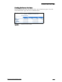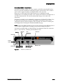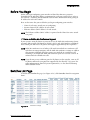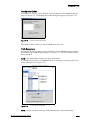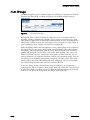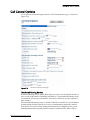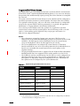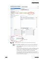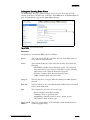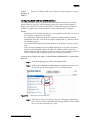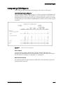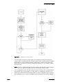
1
3HORE4EL
!DMINISTRATION'UIDE
Document and Software Copyrights
Copyright © 1998–2007 by ShoreTel, Inc., Sunnyvale, California, U.S.A. All rights reserved.
Printed in the United States of America. Contents of this publication may not be reproduced or
transmitted in any form or by any means, electronic or mechanical, for any purpose, without prior
written authorization of ShoreTel, Inc.
ShoreTel, Inc. reserves the right to make changes without notice to the specifications and
materials contained herein and shall not be responsible for any damage (including consequential)
caused by reliance on the materials presented, including, but not limited
to, typographical, arithmetic, or listing errors.
Trademarks
ShoreCare, ShoreWare and ShoreGear are registered trademarks of ShoreTel, Inc. in the United
States and/or other countries.
ShoreTel, ShorePhone, Office Anywhere and ShoreTel Smart are trademarks of ShoreTel, Inc. in the
United States and/or other countries.
Microsoft, Windows, Windows NT, and ActiveX are either registered trademarks or trademarks of
Microsoft Corporation in the United States and/or other countries. VxWorks is a trademark of
Wind River Systems. All other copyrights and trademarks herein are the property of their
respective owners.
Patents
This product is covered by one or more of the following patents: United States Patent 6,996,059,
United States Patent 7,003,091. ShoreTel, Inc. All rights reserved.
Version Information
ShoreTel 7.5 Administration Guide
Part Number: 800-1029-05
Revision 0
Date: July 12, 2007
Company Information
ShoreTel, Inc.
960 Stewart Drive
Sunnyvale, California 94085
(408) 331-3300
(408) 331-3333 fax
www.shoretel.com
Contents
PREFACE
Objectives . . . . . . . . . . . . . . . . . . . . . . . . . . . . . . . . . . . . . . . . . . . . . . . . . . . . . . . . . . . . . . . . . . . . . . . . . Preface-xi
Audience . . . . . . . . . . . . . . . . . . . . . . . . . . . . . . . . . . . . . . . . . . . . . . . . . . . . . . . . . . . . . . . . . . . . . . . . . . Preface-xi
Organization . . . . . . . . . . . . . . . . . . . . . . . . . . . . . . . . . . . . . . . . . . . . . . . . . . . . . . . . . . . . . . . . . . . . . . . Preface-xi
Documentation Overview . . . . . . . . . . . . . . . . . . . . . . . . . . . . . . . . . . . . . . . . . . . . . . . . . . . . . . . . . . . . . Preface-xii
System Documentation . . . . . . . . . . . . . . . . . . . . . . . . . . . . . . . . . . . . . . . . . . . . . . . . . . . . . . . . . . . Preface-xii
Hardware Documentation . . . . . . . . . . . . . . . . . . . . . . . . . . . . . . . . . . . . . . . . . . . . . . . . . . . . . . . . . Preface-xii
User Documentation . . . . . . . . . . . . . . . . . . . . . . . . . . . . . . . . . . . . . . . . . . . . . . . . . . . . . . . . . . . . . Preface-xii
Release Notes . . . . . . . . . . . . . . . . . . . . . . . . . . . . . . . . . . . . . . . . . . . . . . . . . . . . . . . . . . . . . . . . . Preface-xiii
Online Knowledge Base. . . . . . . . . . . . . . . . . . . . . . . . . . . . . . . . . . . . . . . . . . . . . . . . . . . . . . . . . . Preface-xiii
Document Conventions. . . . . . . . . . . . . . . . . . . . . . . . . . . . . . . . . . . . . . . . . . . . . . . . . . . . . . . . . . . . . . Preface-xiii
CHAPTER 1: USING SHOREWARE DIRECTOR
Overview of ShoreWare Director . . . . . . . . . . . . . . . . . . . . . . . . . . . . . . . . . . . . . . . . . . . . . . . . . . . . . . . . . . . . 1-1
Architectural Overview. . . . . . . . . . . . . . . . . . . . . . . . . . . . . . . . . . . . . . . . . . . . . . . . . . . . . . . . . . . . . . . . . 1-2
Multi-level Management . . . . . . . . . . . . . . . . . . . . . . . . . . . . . . . . . . . . . . . . . . . . . . . . . . . . . . . . . . . . . . . 1-2
Multi-user Management. . . . . . . . . . . . . . . . . . . . . . . . . . . . . . . . . . . . . . . . . . . . . . . . . . . . . . . . . . . . . . . . 1-3
External Telephone Number Formatting . . . . . . . . . . . . . . . . . . . . . . . . . . . . . . . . . . . . . . . . . . . . . . . . . . . 1-3
Preferences . . . . . . . . . . . . . . . . . . . . . . . . . . . . . . . . . . . . . . . . . . . . . . . . . . . . . . . . . . . . . . . . . . . . . . . . . 1-4
Prompts . . . . . . . . . . . . . . . . . . . . . . . . . . . . . . . . . . . . . . . . . . . . . . . . . . . . . . . . . . . . . . . . . . . . . . . . . . . . 1-5
Login . . . . . . . . . . . . . . . . . . . . . . . . . . . . . . . . . . . . . . . . . . . . . . . . . . . . . . . . . . . . . . . . . . . . . . . . . . . . . . . . . . 1-6
Product Registration . . . . . . . . . . . . . . . . . . . . . . . . . . . . . . . . . . . . . . . . . . . . . . . . . . . . . . . . . . . . . . . . . . . . . . 1-7
Navigation Frame . . . . . . . . . . . . . . . . . . . . . . . . . . . . . . . . . . . . . . . . . . . . . . . . . . . . . . . . . . . . . . . . . . . . . . . . 1-8
Getting Help . . . . . . . . . . . . . . . . . . . . . . . . . . . . . . . . . . . . . . . . . . . . . . . . . . . . . . . . . . . . . . . . . . . . . . . . 1-9
Logging Off . . . . . . . . . . . . . . . . . . . . . . . . . . . . . . . . . . . . . . . . . . . . . . . . . . . . . . . . . . . . . . . . . . . . . . . . 1-10
Data-Entry Frame . . . . . . . . . . . . . . . . . . . . . . . . . . . . . . . . . . . . . . . . . . . . . . . . . . . . . . . . . . . . . . . . . . . . . . . 1-10
List Pages . . . . . . . . . . . . . . . . . . . . . . . . . . . . . . . . . . . . . . . . . . . . . . . . . . . . . . . . . . . . . . . . . . . . . . . . . . 1-10
Edit Pages . . . . . . . . . . . . . . . . . . . . . . . . . . . . . . . . . . . . . . . . . . . . . . . . . . . . . . . . . . . . . . . . . . . . . . . . . 1-12
Getting Started . . . . . . . . . . . . . . . . . . . . . . . . . . . . . . . . . . . . . . . . . . . . . . . . . . . . . . . . . . . . . . . . . . . . . . . . . 1-13
CHAPTER 2: SETTING UP SYSTEM PARAMETERS
Dialing Plan . . . . . . . . . . . . . . . . . . . . . . . . . . . . . . . . . . . . . . . . . . . . . . . . . . . . . . . . . . . . . . . . . . . . . . . . . . . . . 2-2
Parameters . . . . . . . . . . . . . . . . . . . . . . . . . . . . . . . . . . . . . . . . . . . . . . . . . . . . . . . . . . . . . . . . . . . . . . . . . . 2-3
Increasing Extension Length . . . . . . . . . . . . . . . . . . . . . . . . . . . . . . . . . . . . . . . . . . . . . . . . . . . . . . . . . . . . 2-5
Digit Translation Tables. . . . . . . . . . . . . . . . . . . . . . . . . . . . . . . . . . . . . . . . . . . . . . . . . . . . . . . . . . . . . . . . . . . . 2-6
System Extensions. . . . . . . . . . . . . . . . . . . . . . . . . . . . . . . . . . . . . . . . . . . . . . . . . . . . . . . . . . . . . . . . . . . . . . . . 2-7
Parameters . . . . . . . . . . . . . . . . . . . . . . . . . . . . . . . . . . . . . . . . . . . . . . . . . . . . . . . . . . . . . . . . . . . . . . . . . . 2-8
SNMP . . . . . . . . . . . . . . . . . . . . . . . . . . . . . . . . . . . . . . . . . . . . . . . . . . . . . . . . . . . . . . . . . . . . . . . . . . . . . . . . . 2-9
Parameters . . . . . . . . . . . . . . . . . . . . . . . . . . . . . . . . . . . . . . . . . . . . . . . . . . . . . . . . . . . . . . . . . . . . . . . . . 2-10
BOOTP Server . . . . . . . . . . . . . . . . . . . . . . . . . . . . . . . . . . . . . . . . . . . . . . . . . . . . . . . . . . . . . . . . . . . . . . . . . . 2-11
Other Parameters . . . . . . . . . . . . . . . . . . . . . . . . . . . . . . . . . . . . . . . . . . . . . . . . . . . . . . . . . . . . . . . . . . . . . . . 2-12
Parameters . . . . . . . . . . . . . . . . . . . . . . . . . . . . . . . . . . . . . . . . . . . . . . . . . . . . . . . . . . . . . . . . . . . . . . . . . 2-12
Languages . . . . . . . . . . . . . . . . . . . . . . . . . . . . . . . . . . . . . . . . . . . . . . . . . . . . . . . . . . . . . . . . . . . . . . . . . . . . . 2-13
Licenses . . . . . . . . . . . . . . . . . . . . . . . . . . . . . . . . . . . . . . . . . . . . . . . . . . . . . . . . . . . . . . . . . . . . . . . . . . . . . . . 2-14
Keyed License Types . . . . . . . . . . . . . . . . . . . . . . . . . . . . . . . . . . . . . . . . . . . . . . . . . . . . . . . . . . . . . . . . . 2-16
Extension Licenses . . . . . . . . . . . . . . . . . . . . . . . . . . . . . . . . . . . . . . . . . . . . . . . . . . . . . . . . . . . . . . . . . . . 2-17
Mailbox Licenses . . . . . . . . . . . . . . . . . . . . . . . . . . . . . . . . . . . . . . . . . . . . . . . . . . . . . . . . . . . . . . . . . . . . 2-17
Additional Language Licenses . . . . . . . . . . . . . . . . . . . . . . . . . . . . . . . . . . . . . . . . . . . . . . . . . . . . . . . . . . 2-17
Self-Audited Licenses. . . . . . . . . . . . . . . . . . . . . . . . . . . . . . . . . . . . . . . . . . . . . . . . . . . . . . . . . . . . . . . . . 2-19
Contact Information . . . . . . . . . . . . . . . . . . . . . . . . . . . . . . . . . . . . . . . . . . . . . . . . . . . . . . . . . . . . . . . . . . . . . 2-20
Parameters . . . . . . . . . . . . . . . . . . . . . . . . . . . . . . . . . . . . . . . . . . . . . . . . . . . . . . . . . . . . . . . . . . . . . . . . . 2-21
Sending Contact Information . . . . . . . . . . . . . . . . . . . . . . . . . . . . . . . . . . . . . . . . . . . . . . . . . . . . . . . . . . . 2-21
Administrative Permissions . . . . . . . . . . . . . . . . . . . . . . . . . . . . . . . . . . . . . . . . . . . . . . . . . . . . . . . . . . . . . . . . 2-22
ShoreTel 7.5 Administration Guide
TOC – iii
Parameters . . . . . . . . . . . . . . . . . . . . . . . . . . . . . . . . . . . . . . . . . . . . . . . . . . . . . . . . . . . . . . . . . . . . . . . . . 2-24
Assigning an Administrative Role to a User . . . . . . . . . . . . . . . . . . . . . . . . . . . . . . . . . . . . . . . . . . . . . . . . 2-27
CHAPTER 3: SHORETEL SITES
Overview . . . . . . . . . . . . . . . . . . . . . . . . . . . . . . . . . . . . . . . . . . . . . . . . . . . . . . . . . . . . . . . . . . . . . . . . . . . . . . . 3-1
Configuring Sites. . . . . . . . . . . . . . . . . . . . . . . . . . . . . . . . . . . . . . . . . . . . . . . . . . . . . . . . . . . . . . . . . . . . . . . . . 3-2
Parameters. . . . . . . . . . . . . . . . . . . . . . . . . . . . . . . . . . . . . . . . . . . . . . . . . . . . . . . . . . . . . . . . . . . . . . . . . . . . . . 3-2
CHAPTER 4: CONFIGURING APPLICATION SERVERS
Overview . . . . . . . . . . . . . . . . . . . . . . . . . . . . . . . . . . . . . . . . . . . . . . . . . . . . . . . . . . . . . . . . . . . . . . . . . . . . . . . 4-1
Distributed Voice Mail . . . . . . . . . . . . . . . . . . . . . . . . . . . . . . . . . . . . . . . . . . . . . . . . . . . . . . . . . . . . . . . . . . . . . 4-2
Legacy Voice Mail Integration. . . . . . . . . . . . . . . . . . . . . . . . . . . . . . . . . . . . . . . . . . . . . . . . . . . . . . . . . . . . . . . 4-3
Adding Application Servers. . . . . . . . . . . . . . . . . . . . . . . . . . . . . . . . . . . . . . . . . . . . . . . . . . . . . . . . . . . . . . . . . 4-4
Parameters . . . . . . . . . . . . . . . . . . . . . . . . . . . . . . . . . . . . . . . . . . . . . . . . . . . . . . . . . . . . . . . . . . . . . . . . . . 4-6
Extension List Mapping . . . . . . . . . . . . . . . . . . . . . . . . . . . . . . . . . . . . . . . . . . . . . . . . . . . . . . . . . . . . . . . . 4-9
Fax Servers . . . . . . . . . . . . . . . . . . . . . . . . . . . . . . . . . . . . . . . . . . . . . . . . . . . . . . . . . . . . . . . . . . . . . . . . . . . . 4-10
CHAPTER 5: CONFIGURING CONFERENCE BRIDGES
Adding a Conference Bridge Server . . . . . . . . . . . . . . . . . . . . . . . . . . . . . . . . . . . . . . . . . . . . . . . . . . . . . . . . . . 5-1
Parameters . . . . . . . . . . . . . . . . . . . . . . . . . . . . . . . . . . . . . . . . . . . . . . . . . . . . . . . . . . . . . . . . . . . . . . . . . . 5-2
Checking Conference Port Status . . . . . . . . . . . . . . . . . . . . . . . . . . . . . . . . . . . . . . . . . . . . . . . . . . . . . . . . 5-3
CHAPTER 6: CONFIGURING SWITCHES
Overview . . . . . . . . . . . . . . . . . . . . . . . . . . . . . . . . . . . . . . . . . . . . . . . . . . . . . . . . . . . . . . . . . . . . . . . . . . . . . . . 6-1
Backup Operator . . . . . . . . . . . . . . . . . . . . . . . . . . . . . . . . . . . . . . . . . . . . . . . . . . . . . . . . . . . . . . . . . . . . . 6-1
Switch Models . . . . . . . . . . . . . . . . . . . . . . . . . . . . . . . . . . . . . . . . . . . . . . . . . . . . . . . . . . . . . . . . . . . . . . . 6-2
SG-90, -50, -220T1, and -220E1 Voice Switches. . . . . . . . . . . . . . . . . . . . . . . . . . . . . . . . . . . . . . . . . . . . . . . . . 6-3
ShoreGear-90 Voice Switch . . . . . . . . . . . . . . . . . . . . . . . . . . . . . . . . . . . . . . . . . . . . . . . . . . . . . . . . . . . . . 6-3
ShoreGear-50 Voice Switch . . . . . . . . . . . . . . . . . . . . . . . . . . . . . . . . . . . . . . . . . . . . . . . . . . . . . . . . . . . . . 6-6
ShoreGear-220T1 Voice Switch . . . . . . . . . . . . . . . . . . . . . . . . . . . . . . . . . . . . . . . . . . . . . . . . . . . . . . . . . . 6-9
ShoreGear-220E1 Voice Switch . . . . . . . . . . . . . . . . . . . . . . . . . . . . . . . . . . . . . . . . . . . . . . . . . . . . . . . . . 6-13
SG-120/24, -60/12, -40/8, and -T1 Switches. . . . . . . . . . . . . . . . . . . . . . . . . . . . . . . . . . . . . . . . . . . . . . . . . . . 6-17
ShoreGear-120/24 Voice Switch . . . . . . . . . . . . . . . . . . . . . . . . . . . . . . . . . . . . . . . . . . . . . . . . . . . . . . . . 6-17
ShoreGear-60/12 Voice Switch . . . . . . . . . . . . . . . . . . . . . . . . . . . . . . . . . . . . . . . . . . . . . . . . . . . . . . . . . 6-20
ShoreGear-40/8 Voice Switch . . . . . . . . . . . . . . . . . . . . . . . . . . . . . . . . . . . . . . . . . . . . . . . . . . . . . . . . . . 6-23
ShoreGear-T1 Voice Switch. . . . . . . . . . . . . . . . . . . . . . . . . . . . . . . . . . . . . . . . . . . . . . . . . . . . . . . . . . . . 6-26
IPBX-24, -12, -Teleworker, -T1, and -E1 Switches . . . . . . . . . . . . . . . . . . . . . . . . . . . . . . . . . . . . . . . . . . . . . . . 6-29
ShoreGear-24 Voice Switch . . . . . . . . . . . . . . . . . . . . . . . . . . . . . . . . . . . . . . . . . . . . . . . . . . . . . . . . . . . . 6-29
IPBX-12 Port Voice Switch . . . . . . . . . . . . . . . . . . . . . . . . . . . . . . . . . . . . . . . . . . . . . . . . . . . . . . . . . . . . . 6-32
ShoreGear-Teleworker (IPBX-TW) Voice Switch. . . . . . . . . . . . . . . . . . . . . . . . . . . . . . . . . . . . . . . . . . . . . 6-35
ShoreGear-T1 and ShoreGear-E1 Voice Switch . . . . . . . . . . . . . . . . . . . . . . . . . . . . . . . . . . . . . . . . . . . . . 6-38
Before You Begin . . . . . . . . . . . . . . . . . . . . . . . . . . . . . . . . . . . . . . . . . . . . . . . . . . . . . . . . . . . . . . . . . . . . . . . 6-41
IP Phone and Make Me Conference Support . . . . . . . . . . . . . . . . . . . . . . . . . . . . . . . . . . . . . . . . . . . . . . 6-41
Switches List Page . . . . . . . . . . . . . . . . . . . . . . . . . . . . . . . . . . . . . . . . . . . . . . . . . . . . . . . . . . . . . . . . . . . . . . . 6-41
ShoreGear-120/24, 60/12, 40/8 Configuration . . . . . . . . . . . . . . . . . . . . . . . . . . . . . . . . . . . . . . . . . . . . . . . . . 6-44
ShoreGear-120/24, -60/12, -40/8 Parameters . . . . . . . . . . . . . . . . . . . . . . . . . . . . . . . . . . . . . . . . . . . . . . 6-44
Parameters . . . . . . . . . . . . . . . . . . . . . . . . . . . . . . . . . . . . . . . . . . . . . . . . . . . . . . . . . . . . . . . . . . . . . . . . . 6-46
Adding a ShoreGear-120/24, -60/12, -40/8. . . . . . . . . . . . . . . . . . . . . . . . . . . . . . . . . . . . . . . . . . . . . . . . 6-46
ShoreGear-T1 Configuration . . . . . . . . . . . . . . . . . . . . . . . . . . . . . . . . . . . . . . . . . . . . . . . . . . . . . . . . . . . . . . . 6-48
ShoreGear-T1 Parameters . . . . . . . . . . . . . . . . . . . . . . . . . . . . . . . . . . . . . . . . . . . . . . . . . . . . . . . . . . . . . 6-49
Adding a ShoreGear-T1 . . . . . . . . . . . . . . . . . . . . . . . . . . . . . . . . . . . . . . . . . . . . . . . . . . . . . . . . . . . . . . . 6-51
ShoreGear-E1 Configuration . . . . . . . . . . . . . . . . . . . . . . . . . . . . . . . . . . . . . . . . . . . . . . . . . . . . . . . . . . . . . . . 6-53
ShoreGear-E1 Parameters . . . . . . . . . . . . . . . . . . . . . . . . . . . . . . . . . . . . . . . . . . . . . . . . . . . . . . . . . . . . . 6-54
Adding a ShoreGear-E1 . . . . . . . . . . . . . . . . . . . . . . . . . . . . . . . . . . . . . . . . . . . . . . . . . . . . . . . . . . . . . . . 6-55
SoftSwitch . . . . . . . . . . . . . . . . . . . . . . . . . . . . . . . . . . . . . . . . . . . . . . . . . . . . . . . . . . . . . . . . . . . . . . . . . . . . . 6-56
Parameters . . . . . . . . . . . . . . . . . . . . . . . . . . . . . . . . . . . . . . . . . . . . . . . . . . . . . . . . . . . . . . . . . . . . . . . . . 6-56
Replacing a ShoreGear Voice Switch . . . . . . . . . . . . . . . . . . . . . . . . . . . . . . . . . . . . . . . . . . . . . . . . . . . . . . . . 6-57
CHAPTER 7: CONFIGURING TRUNKS
TOC – iv
ShoreTel, Inc.
Overview . . . . . . . . . . . . . . . . . . . . . . . . . . . . . . . . . . . . . . . . . . . . . . . . . . . . . . . . . . . . . . . . . . . . . . . . . . . . . . . 7-1
Setting Up Trunks . . . . . . . . . . . . . . . . . . . . . . . . . . . . . . . . . . . . . . . . . . . . . . . . . . . . . . . . . . . . . . . . . . . . . . . . 7-2
Add or Edit a Trunk Group. . . . . . . . . . . . . . . . . . . . . . . . . . . . . . . . . . . . . . . . . . . . . . . . . . . . . . . . . . . . . . 7-2
Importing Local Prefixes. . . . . . . . . . . . . . . . . . . . . . . . . . . . . . . . . . . . . . . . . . . . . . . . . . . . . . . . . . . . . . . 7-10
Edit DID Range . . . . . . . . . . . . . . . . . . . . . . . . . . . . . . . . . . . . . . . . . . . . . . . . . . . . . . . . . . . . . . . . . . . . . 7-13
Edit DNIS Digit Map . . . . . . . . . . . . . . . . . . . . . . . . . . . . . . . . . . . . . . . . . . . . . . . . . . . . . . . . . . . . . . . . . 7-13
Additional Local Area Codes . . . . . . . . . . . . . . . . . . . . . . . . . . . . . . . . . . . . . . . . . . . . . . . . . . . . . . . . . . . 7-14
Nearby Area Codes . . . . . . . . . . . . . . . . . . . . . . . . . . . . . . . . . . . . . . . . . . . . . . . . . . . . . . . . . . . . . . . . . . 7-15
Prefix Exceptions . . . . . . . . . . . . . . . . . . . . . . . . . . . . . . . . . . . . . . . . . . . . . . . . . . . . . . . . . . . . . . . . . . . . 7-15
Off-System Extensions . . . . . . . . . . . . . . . . . . . . . . . . . . . . . . . . . . . . . . . . . . . . . . . . . . . . . . . . . . . . . . . . 7-16
Tandem Trunking . . . . . . . . . . . . . . . . . . . . . . . . . . . . . . . . . . . . . . . . . . . . . . . . . . . . . . . . . . . . . . . . . . . . 7-16
Centrex Flash . . . . . . . . . . . . . . . . . . . . . . . . . . . . . . . . . . . . . . . . . . . . . . . . . . . . . . . . . . . . . . . . . . . . . . . 7-17
Individual Trunks . . . . . . . . . . . . . . . . . . . . . . . . . . . . . . . . . . . . . . . . . . . . . . . . . . . . . . . . . . . . . . . . . . . . . . . . 7-18
Add or Edit a Trunk . . . . . . . . . . . . . . . . . . . . . . . . . . . . . . . . . . . . . . . . . . . . . . . . . . . . . . . . . . . . . . . . . . 7-19
CHAPTER 8: CONFIGURING IP PHONES
Overview . . . . . . . . . . . . . . . . . . . . . . . . . . . . . . . . . . . . . . . . . . . . . . . . . . . . . . . . . . . . . . . . . . . . . . . . . . . . . . . 8-1
Setting IP Address Ranges . . . . . . . . . . . . . . . . . . . . . . . . . . . . . . . . . . . . . . . . . . . . . . . . . . . . . . . . . . . . . . . . . 8-2
IP Phone Address Map . . . . . . . . . . . . . . . . . . . . . . . . . . . . . . . . . . . . . . . . . . . . . . . . . . . . . . . . . . . . . . . . . . . . 8-2
Adding Teleworking IP Phones . . . . . . . . . . . . . . . . . . . . . . . . . . . . . . . . . . . . . . . . . . . . . . . . . . . . . . . . . . 8-2
Setting IP Phone Options . . . . . . . . . . . . . . . . . . . . . . . . . . . . . . . . . . . . . . . . . . . . . . . . . . . . . . . . . . . . . . . . . . 8-4
Adding Individual IP Phones Users . . . . . . . . . . . . . . . . . . . . . . . . . . . . . . . . . . . . . . . . . . . . . . . . . . . . . . . . . . . 8-5
Adding Users with Any IP Phone . . . . . . . . . . . . . . . . . . . . . . . . . . . . . . . . . . . . . . . . . . . . . . . . . . . . . . . . . 8-5
Assigning IP Phones by User . . . . . . . . . . . . . . . . . . . . . . . . . . . . . . . . . . . . . . . . . . . . . . . . . . . . . . . . . . . . 8-8
Viewing and Editing IP Phones on the System . . . . . . . . . . . . . . . . . . . . . . . . . . . . . . . . . . . . . . . . . . . . . . . . . . 8-8
Viewing IP Phones . . . . . . . . . . . . . . . . . . . . . . . . . . . . . . . . . . . . . . . . . . . . . . . . . . . . . . . . . . . . . . . . . . . . 8-9
Renaming IP Phones . . . . . . . . . . . . . . . . . . . . . . . . . . . . . . . . . . . . . . . . . . . . . . . . . . . . . . . . . . . . . . . . . . 8-9
Deleting and Moving IP Phones. . . . . . . . . . . . . . . . . . . . . . . . . . . . . . . . . . . . . . . . . . . . . . . . . . . . . . . . . . 8-9
IP Phone State Display . . . . . . . . . . . . . . . . . . . . . . . . . . . . . . . . . . . . . . . . . . . . . . . . . . . . . . . . . . . . . . . . 8-10
Displaying ShorePhone-IP110/115/210/212k/230/530/560/560g Settings. . . . . . . . . . . . . . . . . . . . . . . . 8-11
Resetting the ShorePhone-IP110/115/210/212k/230/530/560/560g . . . . . . . . . . . . . . . . . . . . . . . . . . . . 8-11
Loading Custom Ring Tones . . . . . . . . . . . . . . . . . . . . . . . . . . . . . . . . . . . . . . . . . . . . . . . . . . . . . . . . . . . . . . . 8-11
CHAPTER 9: SETTING CALL CONTROL OPTIONS
Account Codes . . . . . . . . . . . . . . . . . . . . . . . . . . . . . . . . . . . . . . . . . . . . . . . . . . . . . . . . . . . . . . . . . . . . . . . . . . 9-3
Adding and Editing Account Codes . . . . . . . . . . . . . . . . . . . . . . . . . . . . . . . . . . . . . . . . . . . . . . . . . . . . . . 9-5
Bridged Call Appearances . . . . . . . . . . . . . . . . . . . . . . . . . . . . . . . . . . . . . . . . . . . . . . . . . . . . . . . . . . . . . . . . . 9-7
Hunt Groups . . . . . . . . . . . . . . . . . . . . . . . . . . . . . . . . . . . . . . . . . . . . . . . . . . . . . . . . . . . . . . . . . . . . . . . . . . . 9-10
Setting the Hunt Group to Busy. . . . . . . . . . . . . . . . . . . . . . . . . . . . . . . . . . . . . . . . . . . . . . . . . . . . . . . . . 9-14
Paging Groups . . . . . . . . . . . . . . . . . . . . . . . . . . . . . . . . . . . . . . . . . . . . . . . . . . . . . . . . . . . . . . . . . . . . . . . . . 9-15
Adding Overhead Paging to Paging Groups. . . . . . . . . . . . . . . . . . . . . . . . . . . . . . . . . . . . . . . . . . . . . . . 9-15
Configuration . . . . . . . . . . . . . . . . . . . . . . . . . . . . . . . . . . . . . . . . . . . . . . . . . . . . . . . . . . . . . . . . . . . . . . . 9-16
Pickup Groups . . . . . . . . . . . . . . . . . . . . . . . . . . . . . . . . . . . . . . . . . . . . . . . . . . . . . . . . . . . . . . . . . . . . . . . . . . 9-18
Configuring Pickup Groups . . . . . . . . . . . . . . . . . . . . . . . . . . . . . . . . . . . . . . . . . . . . . . . . . . . . . . . . . . . . 9-19
Route Points . . . . . . . . . . . . . . . . . . . . . . . . . . . . . . . . . . . . . . . . . . . . . . . . . . . . . . . . . . . . . . . . . . . . . . . . . . . 9-21
Parameters . . . . . . . . . . . . . . . . . . . . . . . . . . . . . . . . . . . . . . . . . . . . . . . . . . . . . . . . . . . . . . . . . . . . . . . . . 9-23
Call Control Options . . . . . . . . . . . . . . . . . . . . . . . . . . . . . . . . . . . . . . . . . . . . . . . . . . . . . . . . . . . . . . . . . . . . . 9-27
Distributed Routing Service . . . . . . . . . . . . . . . . . . . . . . . . . . . . . . . . . . . . . . . . . . . . . . . . . . . . . . . . . . . . 9-27
Parameters . . . . . . . . . . . . . . . . . . . . . . . . . . . . . . . . . . . . . . . . . . . . . . . . . . . . . . . . . . . . . . . . . . . . . . . . . 9-28
CHAPTER 10: CONFIGURING USERS
Overview . . . . . . . . . . . . . . . . . . . . . . . . . . . . . . . . . . . . . . . . . . . . . . . . . . . . . . . . . . . . . . . . . . . . . . . . . . . . . . 10-1
Classes of Service . . . . . . . . . . . . . . . . . . . . . . . . . . . . . . . . . . . . . . . . . . . . . . . . . . . . . . . . . . . . . . . . . . . . . . . 10-2
Telephony Features Permissions . . . . . . . . . . . . . . . . . . . . . . . . . . . . . . . . . . . . . . . . . . . . . . . . . . . . . . . . 10-3
Whisper Page . . . . . . . . . . . . . . . . . . . . . . . . . . . . . . . . . . . . . . . . . . . . . . . . . . . . . . . . . . . . . . . . . . . . . . . 10-8
Call Permissions . . . . . . . . . . . . . . . . . . . . . . . . . . . . . . . . . . . . . . . . . . . . . . . . . . . . . . . . . . . . . . . . . . . . 10-11
Voice Mail Permissions. . . . . . . . . . . . . . . . . . . . . . . . . . . . . . . . . . . . . . . . . . . . . . . . . . . . . . . . . . . . . . . 10-13
User Groups . . . . . . . . . . . . . . . . . . . . . . . . . . . . . . . . . . . . . . . . . . . . . . . . . . . . . . . . . . . . . . . . . . . . . . . . . . 10-16
User Group List Page Column Definitions . . . . . . . . . . . . . . . . . . . . . . . . . . . . . . . . . . . . . . . . . . . . . . . . 10-16
ShoreTel 7.5 Administration Guide
TOC – v
User Group Parameters . . . . . . . . . . . . . . . . . . . . . . . . . . . . . . . . . . . . . . . . . . . . . . . . . . . . . . . . . . . . . .
Individual Users . . . . . . . . . . . . . . . . . . . . . . . . . . . . . . . . . . . . . . . . . . . . . . . . . . . . . . . . . . . . . . . . . . . . . . . .
Individual Users List Page Column Headings. . . . . . . . . . . . . . . . . . . . . . . . . . . . . . . . . . . . . . . . . . . . . .
Private Numbers. . . . . . . . . . . . . . . . . . . . . . . . . . . . . . . . . . . . . . . . . . . . . . . . . . . . . . . . . . . . . . . . . . . .
User Import Tool . . . . . . . . . . . . . . . . . . . . . . . . . . . . . . . . . . . . . . . . . . . . . . . . . . . . . . . . . . . . . . . . . . .
General Information . . . . . . . . . . . . . . . . . . . . . . . . . . . . . . . . . . . . . . . . . . . . . . . . . . . . . . . . . . . . . . . . .
Parameters . . . . . . . . . . . . . . . . . . . . . . . . . . . . . . . . . . . . . . . . . . . . . . . . . . . . . . . . . . . . . . . . . . . . . . . .
Personal Options . . . . . . . . . . . . . . . . . . . . . . . . . . . . . . . . . . . . . . . . . . . . . . . . . . . . . . . . . . . . . . . . . . .
Voice Mail Delivery and Notifications . . . . . . . . . . . . . . . . . . . . . . . . . . . . . . . . . . . . . . . . . . . . . . . . . . .
Find Me and External Assignment . . . . . . . . . . . . . . . . . . . . . . . . . . . . . . . . . . . . . . . . . . . . . . . . . . . . . .
Programmable IP Phone Buttons . . . . . . . . . . . . . . . . . . . . . . . . . . . . . . . . . . . . . . . . . . . . . . . . . . . . . . .
Programming Personal Call Manager Toolbar . . . . . . . . . . . . . . . . . . . . . . . . . . . . . . . . . . . . . . . . . . . . .
Wireless Headset Hook Switch. . . . . . . . . . . . . . . . . . . . . . . . . . . . . . . . . . . . . . . . . . . . . . . . . . . . . . . . .
System Directory Record . . . . . . . . . . . . . . . . . . . . . . . . . . . . . . . . . . . . . . . . . . . . . . . . . . . . . . . . . . . . .
Distribution Lists. . . . . . . . . . . . . . . . . . . . . . . . . . . . . . . . . . . . . . . . . . . . . . . . . . . . . . . . . . . . . . . . . . . .
Workgroups . . . . . . . . . . . . . . . . . . . . . . . . . . . . . . . . . . . . . . . . . . . . . . . . . . . . . . . . . . . . . . . . . . . . . . .
Notify Users . . . . . . . . . . . . . . . . . . . . . . . . . . . . . . . . . . . . . . . . . . . . . . . . . . . . . . . . . . . . . . . . . . . . . . . . . . .
Anonymous Telephones . . . . . . . . . . . . . . . . . . . . . . . . . . . . . . . . . . . . . . . . . . . . . . . . . . . . . . . . . . . . . . . . .
Extension Lists . . . . . . . . . . . . . . . . . . . . . . . . . . . . . . . . . . . . . . . . . . . . . . . . . . . . . . . . . . . . . . . . . . . . . . . . .
Paging Through a List . . . . . . . . . . . . . . . . . . . . . . . . . . . . . . . . . . . . . . . . . . . . . . . . . . . . . . . . . . . . . . .
Batch Update Utility . . . . . . . . . . . . . . . . . . . . . . . . . . . . . . . . . . . . . . . . . . . . . . . . . . . . . . . . . . . . . . . . . . . .
Batch Update . . . . . . . . . . . . . . . . . . . . . . . . . . . . . . . . . . . . . . . . . . . . . . . . . . . . . . . . . . . . . . . . . . . . . .
Call Handling Mode Defaults . . . . . . . . . . . . . . . . . . . . . . . . . . . . . . . . . . . . . . . . . . . . . . . . . . . . . . . . . . . . .
Parameters . . . . . . . . . . . . . . . . . . . . . . . . . . . . . . . . . . . . . . . . . . . . . . . . . . . . . . . . . . . . . . . . . . . . . . . .
Escalation Profiles and Other Mailbox Options . . . . . . . . . . . . . . . . . . . . . . . . . . . . . . . . . . . . . . . . . . . . . . .
Parameters . . . . . . . . . . . . . . . . . . . . . . . . . . . . . . . . . . . . . . . . . . . . . . . . . . . . . . . . . . . . . . . . . . . . . . . .
Configuring Voice Mailbox Full Notifications . . . . . . . . . . . . . . . . . . . . . . . . . . . . . . . . . . . . . . . . . . . . .
Configuring Escalation Notification . . . . . . . . . . . . . . . . . . . . . . . . . . . . . . . . . . . . . . . . . . . . . . . . . . . . .
10-17
10-19
10-19
10-21
10-21
10-25
10-25
10-31
10-36
10-40
10-42
10-53
10-63
10-65
10-65
10-66
10-67
10-68
10-69
10-70
10-71
10-72
10-74
10-75
10-77
10-78
10-80
10-81
CHAPTER 11: CONFIGURING VOICE MAIL
System Distribution Lists . . . . . . . . . . . . . . . . . . . . . . . . . . . . . . . . . . . . . . . . . . . . . . . . . . . . . . . . . . . . . . . . . .
Parameters . . . . . . . . . . . . . . . . . . . . . . . . . . . . . . . . . . . . . . . . . . . . . . . . . . . . . . . . . . . . . . . . . . . . . . . . .
AMIS Voice Mail . . . . . . . . . . . . . . . . . . . . . . . . . . . . . . . . . . . . . . . . . . . . . . . . . . . . . . . . . . . . . . . . . . . . . . . .
AMIS Restrictions . . . . . . . . . . . . . . . . . . . . . . . . . . . . . . . . . . . . . . . . . . . . . . . . . . . . . . . . . . . . . . . . . . . .
Enabling AMIS . . . . . . . . . . . . . . . . . . . . . . . . . . . . . . . . . . . . . . . . . . . . . . . . . . . . . . . . . . . . . . . . . . . . . .
Voice Mail Options . . . . . . . . . . . . . . . . . . . . . . . . . . . . . . . . . . . . . . . . . . . . . . . . . . . . . . . . . . . . . . . . . . . . . .
Creating AMIS Systems . . . . . . . . . . . . . . . . . . . . . . . . . . . . . . . . . . . . . . . . . . . . . . . . . . . . . . . . . . . . . . .
Disabling AMIS Systems. . . . . . . . . . . . . . . . . . . . . . . . . . . . . . . . . . . . . . . . . . . . . . . . . . . . . . . . . . . . . . .
Setting Voice Mail User Group Permissions. . . . . . . . . . . . . . . . . . . . . . . . . . . . . . . . . . . . . . . . . . . . . . . .
AMIS Test Mailbox . . . . . . . . . . . . . . . . . . . . . . . . . . . . . . . . . . . . . . . . . . . . . . . . . . . . . . . . . . . . . . . . . . .
11-1
11-3
11-4
11-5
11-5
11-5
11-6
11-8
11-8
11-8
CHAPTER 12: CONFIGURING THE AUTO-ATTENDANT
Multiple Auto-Attendants . . . . . . . . . . . . . . . . . . . . . . . . . . . . . . . . . . . . . . . . . . . . . . . . . . . . . . . . . . . . . . . . .
Menus . . . . . . . . . . . . . . . . . . . . . . . . . . . . . . . . . . . . . . . . . . . . . . . . . . . . . . . . . . . . . . . . . . . . . . . . . . . . . . . .
Parameters . . . . . . . . . . . . . . . . . . . . . . . . . . . . . . . . . . . . . . . . . . . . . . . . . . . . . . . . . . . . . . . . . . . . . . . . .
Adding and Editing an Auto-Attendant Menu. . . . . . . . . . . . . . . . . . . . . . . . . . . . . . . . . . . . . . . . . . . . . .
Configuring an Auto-Attendant Menu . . . . . . . . . . . . . . . . . . . . . . . . . . . . . . . . . . . . . . . . . . . . . . . . . . . .
12-1
12-2
12-2
12-3
12-7
CHAPTER 13: CONFIGURING SCHEDULES
On-Hours . . . . . . . . . . . . . . . . . . . . . . . . . . . . . . . . . . . . . . . . . . . . . . . . . . . . . . . . . . . . . . . . . . . . . . . . . . 13-3
Holiday Schedule . . . . . . . . . . . . . . . . . . . . . . . . . . . . . . . . . . . . . . . . . . . . . . . . . . . . . . . . . . . . . . . . . . . . 13-4
Custom Schedule . . . . . . . . . . . . . . . . . . . . . . . . . . . . . . . . . . . . . . . . . . . . . . . . . . . . . . . . . . . . . . . . . . . . 13-6
CHAPTER 14: CONFIGURING WORKGROUPS
Overview . . . . . . . . . . . . . . . . . . . . . . . . . . . . . . . . . . . . . . . . . . . . . . . . . . . . . . . . . . . . . . . . . . . . . . . . . . . . . .
Call Routing . . . . . . . . . . . . . . . . . . . . . . . . . . . . . . . . . . . . . . . . . . . . . . . . . . . . . . . . . . . . . . . . . . . . . . . .
Call Distribution . . . . . . . . . . . . . . . . . . . . . . . . . . . . . . . . . . . . . . . . . . . . . . . . . . . . . . . . . . . . . . . . . . . . .
Call Queuing . . . . . . . . . . . . . . . . . . . . . . . . . . . . . . . . . . . . . . . . . . . . . . . . . . . . . . . . . . . . . . . . . . . . . . .
Workgroup Call Managers . . . . . . . . . . . . . . . . . . . . . . . . . . . . . . . . . . . . . . . . . . . . . . . . . . . . . . . . . . . . .
Intercom/Paging, Barge In, Record, and Monitor . . . . . . . . . . . . . . . . . . . . . . . . . . . . . . . . . . . . . . . . . . .
TOC – vi
14-1
14-1
14-1
14-2
14-2
14-3
ShoreTel, Inc.
Reporting . . . . . . . . . . . . . . . . . . . . . . . . . . . . . . . . . . . . . . . . . . . . . . . . . . . . . . . . . . . . . . . . . . . . . . . . . . 14-6
Workgroup Navigation . . . . . . . . . . . . . . . . . . . . . . . . . . . . . . . . . . . . . . . . . . . . . . . . . . . . . . . . . . . . . . . . . . . 14-7
Adding and Editing Workgroups . . . . . . . . . . . . . . . . . . . . . . . . . . . . . . . . . . . . . . . . . . . . . . . . . . . . . . . . . . . 14-8
Selecting a DNIS Trunk Group for DNIS Routing . . . . . . . . . . . . . . . . . . . . . . . . . . . . . . . . . . . . . . . . . . . . . . 14-14
Editing Workgroup Membership. . . . . . . . . . . . . . . . . . . . . . . . . . . . . . . . . . . . . . . . . . . . . . . . . . . . . . . . . . . 14-15
Editing Workgroup Queue Handling . . . . . . . . . . . . . . . . . . . . . . . . . . . . . . . . . . . . . . . . . . . . . . . . . . . . . . . 14-16
Configuring Workgroup Overflow / Interflow . . . . . . . . . . . . . . . . . . . . . . . . . . . . . . . . . . . . . . . . . . . . . 14-19
Workgroup Thresholds . . . . . . . . . . . . . . . . . . . . . . . . . . . . . . . . . . . . . . . . . . . . . . . . . . . . . . . . . . . . . . . . . . 14-21
CHAPTER 15: MANAGING THE SYSTEM DIRECTORY
System Directory . . . . . . . . . . . . . . . . . . . . . . . . . . . . . . . . . . . . . . . . . . . . . . . . . . . . . . . . . . . . . . . . . . . . . . . . 15-1
System Directory Entry Edit Page . . . . . . . . . . . . . . . . . . . . . . . . . . . . . . . . . . . . . . . . . . . . . . . . . . . . . . . 15-3
Data-Entry Fields . . . . . . . . . . . . . . . . . . . . . . . . . . . . . . . . . . . . . . . . . . . . . . . . . . . . . . . . . . . . . . . . . . . . 15-3
CHAPTER 16: MAINTENANCE
Overview . . . . . . . . . . . . . . . . . . . . . . . . . . . . . . . . . . . . . . . . . . . . . . . . . . . . . . . . . . . . . . . . . . . . . . . . . . . . . . 16-1
Quick Look . . . . . . . . . . . . . . . . . . . . . . . . . . . . . . . . . . . . . . . . . . . . . . . . . . . . . . . . . . . . . . . . . . . . . . . . . . . . 16-2
Maintenance Switches Summary . . . . . . . . . . . . . . . . . . . . . . . . . . . . . . . . . . . . . . . . . . . . . . . . . . . . . . . . 16-3
Switch Maintenance . . . . . . . . . . . . . . . . . . . . . . . . . . . . . . . . . . . . . . . . . . . . . . . . . . . . . . . . . . . . . . . . . . . . . 16-7
Switch Section . . . . . . . . . . . . . . . . . . . . . . . . . . . . . . . . . . . . . . . . . . . . . . . . . . . . . . . . . . . . . . . . . . . . . . 16-7
Link Section . . . . . . . . . . . . . . . . . . . . . . . . . . . . . . . . . . . . . . . . . . . . . . . . . . . . . . . . . . . . . . . . . . . . . . . . 16-8
Ports Section . . . . . . . . . . . . . . . . . . . . . . . . . . . . . . . . . . . . . . . . . . . . . . . . . . . . . . . . . . . . . . . . . . . . . . . 16-9
Hunt Groups Section . . . . . . . . . . . . . . . . . . . . . . . . . . . . . . . . . . . . . . . . . . . . . . . . . . . . . . . . . . . . . . . . 16-11
IP Phone Maintenance . . . . . . . . . . . . . . . . . . . . . . . . . . . . . . . . . . . . . . . . . . . . . . . . . . . . . . . . . . . . . . . 16-12
SIP Trunks Section . . . . . . . . . . . . . . . . . . . . . . . . . . . . . . . . . . . . . . . . . . . . . . . . . . . . . . . . . . . . . . . . . . 16-13
Details Section . . . . . . . . . . . . . . . . . . . . . . . . . . . . . . . . . . . . . . . . . . . . . . . . . . . . . . . . . . . . . . . . . . . . . 16-13
ShoreGear-T1 PRI and ShoreGear-E1 PRI Maintenance . . . . . . . . . . . . . . . . . . . . . . . . . . . . . . . . . . . . . 16-14
ShoreGear-12 and -Teleworker Maintenance . . . . . . . . . . . . . . . . . . . . . . . . . . . . . . . . . . . . . . . . . . . . . 16-15
Quick Look Server Maintenance—Main Server . . . . . . . . . . . . . . . . . . . . . . . . . . . . . . . . . . . . . . . . . . . . 16-16
Quick Look Server Maintenance—Distributed Servers . . . . . . . . . . . . . . . . . . . . . . . . . . . . . . . . . . . . . . 16-19
Switch Connectivity . . . . . . . . . . . . . . . . . . . . . . . . . . . . . . . . . . . . . . . . . . . . . . . . . . . . . . . . . . . . . . . . . . . . . 16-20
Conference Ports. . . . . . . . . . . . . . . . . . . . . . . . . . . . . . . . . . . . . . . . . . . . . . . . . . . . . . . . . . . . . . . . . . . . . . . 16-21
Event Log . . . . . . . . . . . . . . . . . . . . . . . . . . . . . . . . . . . . . . . . . . . . . . . . . . . . . . . . . . . . . . . . . . . . . . . . . . . . 16-22
Viewing Event Reports . . . . . . . . . . . . . . . . . . . . . . . . . . . . . . . . . . . . . . . . . . . . . . . . . . . . . . . . . . . . . . . 16-24
Services . . . . . . . . . . . . . . . . . . . . . . . . . . . . . . . . . . . . . . . . . . . . . . . . . . . . . . . . . . . . . . . . . . . . . . . . . . . . . . 16-25
Service Maintenance Page . . . . . . . . . . . . . . . . . . . . . . . . . . . . . . . . . . . . . . . . . . . . . . . . . . . . . . . . . . . . 16-26
Event Filters. . . . . . . . . . . . . . . . . . . . . . . . . . . . . . . . . . . . . . . . . . . . . . . . . . . . . . . . . . . . . . . . . . . . . . . . . . . 16-26
Editing and Creating Event Filters . . . . . . . . . . . . . . . . . . . . . . . . . . . . . . . . . . . . . . . . . . . . . . . . . . . . . . 16-27
CHAPTER 17: REPORTING
Overview . . . . . . . . . . . . . . . . . . . . . . . . . . . . . . . . . . . . . . . . . . . . . . . . . . . . . . . . . . . . . . . . . . . . . . . . . . . . . .
Reports . . . . . . . . . . . . . . . . . . . . . . . . . . . . . . . . . . . . . . . . . . . . . . . . . . . . . . . . . . . . . . . . . . . . . . . . . . . . . . .
Converting Existing CDR Data to MySQL Format . . . . . . . . . . . . . . . . . . . . . . . . . . . . . . . . . . . . . . . . . . .
Options . . . . . . . . . . . . . . . . . . . . . . . . . . . . . . . . . . . . . . . . . . . . . . . . . . . . . . . . . . . . . . . . . . . . . . . . . . . . . . .
Configuring Send CDR Out SMDR Interface . . . . . . . . . . . . . . . . . . . . . . . . . . . . . . . . . . . . . . . . . . . . . . .
Creating the Archive Database . . . . . . . . . . . . . . . . . . . . . . . . . . . . . . . . . . . . . . . . . . . . . . . . . . . . . . . . .
17-1
17-2
17-5
17-6
17-7
17-8
APPENDIX A: USING OFFICE ANYWHERE
Special Considerations . . . . . . . . . . . . . . . . . . . . . . . . . . . . . . . . . . . . . . . . . . . . . . . . . . . . . . . . . . . . . . . . . . . . A-2
Terminology . . . . . . . . . . . . . . . . . . . . . . . . . . . . . . . . . . . . . . . . . . . . . . . . . . . . . . . . . . . . . . . . . . . . . . . . . . . . A-4
Configuring Permission Settings . . . . . . . . . . . . . . . . . . . . . . . . . . . . . . . . . . . . . . . . . . . . . . . . . . . . . . . . . . . . . A-5
Configuring Off-Net External Assignment . . . . . . . . . . . . . . . . . . . . . . . . . . . . . . . . . . . . . . . . . . . . . . . . . . . . . A-7
Configuring On-Net Extension Assignment . . . . . . . . . . . . . . . . . . . . . . . . . . . . . . . . . . . . . . . . . . . . . . . . . . . A-10
Using the Telephone User Interface. . . . . . . . . . . . . . . . . . . . . . . . . . . . . . . . . . . . . . . . . . . . . . . . . . . . . . A-10
Using the ShoreTel Call Manager . . . . . . . . . . . . . . . . . . . . . . . . . . . . . . . . . . . . . . . . . . . . . . . . . . . . . . . A-11
APPENDIX B: EMERGENCY 911 OPERATIONS
Overview . . . . . . . . . . . . . . . . . . . . . . . . . . . . . . . . . . . . . . . . . . . . . . . . . . . . . . . . . . . . . . . . . . . . . . . . . . . . . . . B-1
How 911 Calls Work. . . . . . . . . . . . . . . . . . . . . . . . . . . . . . . . . . . . . . . . . . . . . . . . . . . . . . . . . . . . . . . . . . . B-2
ShoreTel 7.5 Administration Guide
TOC – vii
Roles and Responsibilities . . . . . . . . . . . . . . . . . . . . . . . . . . . . . . . . . . . . . . . . . . . . . . . . . . . . . . . . . . . . . . B-3
Selecting a PS/ALI Service Provider . . . . . . . . . . . . . . . . . . . . . . . . . . . . . . . . . . . . . . . . . . . . . . . . . . . . . . . B-4
Feature Operation. . . . . . . . . . . . . . . . . . . . . . . . . . . . . . . . . . . . . . . . . . . . . . . . . . . . . . . . . . . . . . . . . . . . . . . . B-5
Digit Collection for 911 Calls . . . . . . . . . . . . . . . . . . . . . . . . . . . . . . . . . . . . . . . . . . . . . . . . . . . . . . . . . . . . B-5
Ensuring Proper Routing of 911 Calls . . . . . . . . . . . . . . . . . . . . . . . . . . . . . . . . . . . . . . . . . . . . . . . . . . . . . B-5
Trunk Signaling for 911 Calls . . . . . . . . . . . . . . . . . . . . . . . . . . . . . . . . . . . . . . . . . . . . . . . . . . . . . . . . . . . . B-6
Selecting Caller ID Type for 911 Calls. . . . . . . . . . . . . . . . . . . . . . . . . . . . . . . . . . . . . . . . . . . . . . . . . . . . . . . . . B-7
Available Caller ID Options . . . . . . . . . . . . . . . . . . . . . . . . . . . . . . . . . . . . . . . . . . . . . . . . . . . . . . . . . . . . . B-8
Configuring Your System. . . . . . . . . . . . . . . . . . . . . . . . . . . . . . . . . . . . . . . . . . . . . . . . . . . . . . . . . . . . . . . . . . B-12
Planning Your Emergency Response. . . . . . . . . . . . . . . . . . . . . . . . . . . . . . . . . . . . . . . . . . . . . . . . . . . . . . . . . B-17
International Emergency Numbers . . . . . . . . . . . . . . . . . . . . . . . . . . . . . . . . . . . . . . . . . . . . . . . . . . . . . . . . . . B-19
Special Considerations for Netherlands. . . . . . . . . . . . . . . . . . . . . . . . . . . . . . . . . . . . . . . . . . . . . . . . . . . B-19
Verifying Your 911 Configuration . . . . . . . . . . . . . . . . . . . . . . . . . . . . . . . . . . . . . . . . . . . . . . . . . . . . . . . . . . . B-20
Additional Recommendations . . . . . . . . . . . . . . . . . . . . . . . . . . . . . . . . . . . . . . . . . . . . . . . . . . . . . . . . . . . . . . B-21
APPENDIX C: CALL DETAIL RECORD REPORTS
Overview . . . . . . . . . . . . . . . . . . . . . . . . . . . . . . . . . . . . . . . . . . . . . . . . . . . . . . . . . . . . . . . . . . . . . . . . . . . . . . . C-1
Call Accounting Service . . . . . . . . . . . . . . . . . . . . . . . . . . . . . . . . . . . . . . . . . . . . . . . . . . . . . . . . . . . . . . . . C-1
Active CDR Database. . . . . . . . . . . . . . . . . . . . . . . . . . . . . . . . . . . . . . . . . . . . . . . . . . . . . . . . . . . . . . . . . . C-2
Legacy CDR Text Files . . . . . . . . . . . . . . . . . . . . . . . . . . . . . . . . . . . . . . . . . . . . . . . . . . . . . . . . . . . . . . . . . C-2
MySQL Database. . . . . . . . . . . . . . . . . . . . . . . . . . . . . . . . . . . . . . . . . . . . . . . . . . . . . . . . . . . . . . . . . . . . . . . . . C-4
Compatibility and Pre-Configuration Requirements . . . . . . . . . . . . . . . . . . . . . . . . . . . . . . . . . . . . . . . . . . C-4
Archival and Backup Utilities . . . . . . . . . . . . . . . . . . . . . . . . . . . . . . . . . . . . . . . . . . . . . . . . . . . . . . . . . . . . C-5
Installing MySQL on a Secondary Server . . . . . . . . . . . . . . . . . . . . . . . . . . . . . . . . . . . . . . . . . . . . . . . . . . . C-7
Importing Access Database Files into MySQL Format. . . . . . . . . . . . . . . . . . . . . . . . . . . . . . . . . . . . . . . . . C-8
Performance Tuning for Report Generation. . . . . . . . . . . . . . . . . . . . . . . . . . . . . . . . . . . . . . . . . . . . . . . . C-10
Report generation time – CPU Utilization . . . . . . . . . . . . . . . . . . . . . . . . . . . . . . . . . . . . . . . . . . . . . . . . . C-10
MySQL CDR Database and Internationalization . . . . . . . . . . . . . . . . . . . . . . . . . . . . . . . . . . . . . . . . . . . . C-10
Monitor MySQL service . . . . . . . . . . . . . . . . . . . . . . . . . . . . . . . . . . . . . . . . . . . . . . . . . . . . . . . . . . . . . . . C-10
Tools for browsing MySQL database tables . . . . . . . . . . . . . . . . . . . . . . . . . . . . . . . . . . . . . . . . . . . . . . . C-10
Restrictions in the number of records returned by the MySQL CDR query . . . . . . . . . . . . . . . . . . . . . . . . C-10
Report License Error Condition . . . . . . . . . . . . . . . . . . . . . . . . . . . . . . . . . . . . . . . . . . . . . . . . . . . . . . . . . C-11
CDR Reports . . . . . . . . . . . . . . . . . . . . . . . . . . . . . . . . . . . . . . . . . . . . . . . . . . . . . . . . . . . . . . . . . . . . . . . . . . . C-12
TMS-CDR Media Stream Statistics . . . . . . . . . . . . . . . . . . . . . . . . . . . . . . . . . . . . . . . . . . . . . . . . . . . . . . . C-13
Generating CDR Reports . . . . . . . . . . . . . . . . . . . . . . . . . . . . . . . . . . . . . . . . . . . . . . . . . . . . . . . . . . . . . . C-16
Interpreting CDR Reports . . . . . . . . . . . . . . . . . . . . . . . . . . . . . . . . . . . . . . . . . . . . . . . . . . . . . . . . . . . . . . . . . C-17
User Activity Summary Report . . . . . . . . . . . . . . . . . . . . . . . . . . . . . . . . . . . . . . . . . . . . . . . . . . . . . . . . . . C-17
User Activity Detail Report . . . . . . . . . . . . . . . . . . . . . . . . . . . . . . . . . . . . . . . . . . . . . . . . . . . . . . . . . . . . . C-20
Trunk Activity Summary Report . . . . . . . . . . . . . . . . . . . . . . . . . . . . . . . . . . . . . . . . . . . . . . . . . . . . . . . . . C-23
Trunk Activity Detail Report . . . . . . . . . . . . . . . . . . . . . . . . . . . . . . . . . . . . . . . . . . . . . . . . . . . . . . . . . . . . C-25
Workgroup Agent Summary Report . . . . . . . . . . . . . . . . . . . . . . . . . . . . . . . . . . . . . . . . . . . . . . . . . . . . . C-29
Workgroup Agent Detail Report . . . . . . . . . . . . . . . . . . . . . . . . . . . . . . . . . . . . . . . . . . . . . . . . . . . . . . . . C-34
Workgroup Service Level Summary Report . . . . . . . . . . . . . . . . . . . . . . . . . . . . . . . . . . . . . . . . . . . . . . . . C-37
Workgroup Queue Summary Report . . . . . . . . . . . . . . . . . . . . . . . . . . . . . . . . . . . . . . . . . . . . . . . . . . . . . C-40
Media Stream Summary Report . . . . . . . . . . . . . . . . . . . . . . . . . . . . . . . . . . . . . . . . . . . . . . . . . . . . . . . . . C-44
Media Stream Detail Report. . . . . . . . . . . . . . . . . . . . . . . . . . . . . . . . . . . . . . . . . . . . . . . . . . . . . . . . . . . . C-46
Account Code Summary Report . . . . . . . . . . . . . . . . . . . . . . . . . . . . . . . . . . . . . . . . . . . . . . . . . . . . . . . . C-48
Account Code Detail Report . . . . . . . . . . . . . . . . . . . . . . . . . . . . . . . . . . . . . . . . . . . . . . . . . . . . . . . . . . . C-51
CDR Database . . . . . . . . . . . . . . . . . . . . . . . . . . . . . . . . . . . . . . . . . . . . . . . . . . . . . . . . . . . . . . . . . . . . . . . . . . C-52
Call Table . . . . . . . . . . . . . . . . . . . . . . . . . . . . . . . . . . . . . . . . . . . . . . . . . . . . . . . . . . . . . . . . . . . . . . . . . . C-53
Enumeration Tables: Use for the Call Table. . . . . . . . . . . . . . . . . . . . . . . . . . . . . . . . . . . . . . . . . . . . . . . . C-56
Connect Table . . . . . . . . . . . . . . . . . . . . . . . . . . . . . . . . . . . . . . . . . . . . . . . . . . . . . . . . . . . . . . . . . . . . . . . . . . C-57
Enumeration Tables Used for Connect Table . . . . . . . . . . . . . . . . . . . . . . . . . . . . . . . . . . . . . . . . . . . . . . C-60
MediaStream Table . . . . . . . . . . . . . . . . . . . . . . . . . . . . . . . . . . . . . . . . . . . . . . . . . . . . . . . . . . . . . . . . . . . . . . C-63
AgentActivity Table. . . . . . . . . . . . . . . . . . . . . . . . . . . . . . . . . . . . . . . . . . . . . . . . . . . . . . . . . . . . . . . . . . . . . . C-64
Enumeration Tables Used for AgentActivity . . . . . . . . . . . . . . . . . . . . . . . . . . . . . . . . . . . . . . . . . . . . . . . C-66
QueueCall Table . . . . . . . . . . . . . . . . . . . . . . . . . . . . . . . . . . . . . . . . . . . . . . . . . . . . . . . . . . . . . . . . . . . . . . . . C-66
Enumeration Tables Used for QueueCall. . . . . . . . . . . . . . . . . . . . . . . . . . . . . . . . . . . . . . . . . . . . . . . . . . C-69
QueueStep Table . . . . . . . . . . . . . . . . . . . . . . . . . . . . . . . . . . . . . . . . . . . . . . . . . . . . . . . . . . . . . . . . . . . . . . . C-70
TOC – viii
ShoreTel, Inc.
INDEX
ShoreTel 7.5 Administration Guide
TOC – ix
TOC – x
ShoreTel, Inc.
Preface
This preface provides information about the objectives, organization, and conventions
of the ShoreTel 7.5 Administration Guide.
Objectives
This guide explains how to use ShoreWare Director to configure, administer, and
maintain the Shoreline Communications System.
The planning and installation procedures are covered in the ShoreTel 7.5 Planning and
Installation Guide.
Audience
This guide is written for the person who uses ShoreWare Director to administer and
maintain the Shoreline Communications System.
Organization
This guide is organized to reflect the order in which you initially configure the
Shoreline Communications System.
The “Getting Started” section in the next chapter provides an ordered checklist to be
used the first time you configure your system.
ShoreTel 7.5 Administration Guide
Preface – xi
Preface
Documentation Overview
The ShoreTel system is documented as described in the following sections.
System Documentation
The following system documents are in the documentation folder on the ShoreWare
DVD and can also be accessed from ShoreWare Director:
• ShoreTel 7.5 Planning and Installation Guide provides information on how to plan
the implementation of the ShoreTel system, as well as how to install the necessary
hardware, data communications, and telecommunications elements. The ShoreTel
7.5 Planning and Installation Guide can be used in conjunction with the ShoreCare
ControlPoint project management tool.
• ShoreTel 7.5 Administration Guide (this guide) provides detailed information on
how to administer and maintain the ShoreTel system using ShoreWare Director.
This includes task-based information, as well as screen-by-screen information
regarding ShoreWare Director.
Hardware Documentation
The following hardware installation documents are packaged with their associated
ShoreGear voice switch or ShoreTel IP phone:
•
•
•
•
•
•
•
•
•
•
•
•
ShoreGear-120/24 Quick Install Guide
ShoreGear 90 Quick Install Guide
ShoreGear 90BRI Quick Install Guide
ShoreGear-60/12 Quick Install Guide
ShoreGear 50 Quick Install Guide
ShoreGear-40/8 Quick Install Guide
ShoreGear-T1 Quick Install Guide
ShoreGear-E1 Quick Install Guide
ShoreGear 220T1 Quick Install Guide
ShoreGear 220T1A Quick Install Guide
ShoreGear 220E1 Quick Install Guide
ShoreTel IP Phone Quick Install Guide
If you have also purchased one or more ShoreTel Converged Conference Bridges, please
refer to the ShoreTel Conference Bridge Quick Install Guide and the ShoreTel Converged
Conference Solution Administration Guide.
If you have purchased the ShoreTel Contact Center Solution, please refer to the ShoreTel
Contact Center Solution Administration Guide and the ShoreTel Contact Center Solution
Planning and Installation Guide.
User Documentation
End-user documentation is installed during the ShoreWare Call Manager installation.
To access it, choose the Help > Contents and Index menu item within the ShoreWare
Call Manager application.
The Telephone User Interface Analog Quick Reference and the Telephone User
Interface IP Phone Quick Reference are available from the ShoreTel web site at
www.shoretel.com, as well as from ShoreWare Director.
Preface – xii
ShoreTel, Inc.
Preface
Release Notes
The release notes listed below provide information about new releases and new features
as well as installation and upgrade information. They can be found in the
documentation folder on the associated DVD and can also be accessed from ShoreWare
Director.
• ShoreWare Server Release Notes
• ShoreWare Call Manager Release Notes
Online Knowledge Base
To access additional information about the release or to resolve issues with the product,
use the ShoreTel Communications Online Knowledge Base, accessible from the
ShoreTel web site at www.shoretel.com.
Document Conventions
The following conventions are used in this guide:
• Data-entry fields, hypertext links, control buttons, keywords, and other items
within the system management interface are in a boldface font.
• Information that you enter in data fields are in a data_entry font.
• NOTE indicates notes to the reader that contain useful information or references.
ShoreTel 7.5 Administration Guide
Preface – xiii
Preface
Preface – xiv
ShoreTel, Inc.
C
H
A
P
T
E
R
1
Using ShoreWare Director
This chapter provides information about using ShoreWare Director. Sections in this
chapter include:
•
•
•
•
•
•
Overview of ShoreWare Director
Login
Product Registration
Navigation Frame
Data-Entry Frame
Getting Started
Overview of ShoreWare Director
ShoreWare Director is a web-based administration and maintenance tool that lets you
manage your ShoreTel 7.5TM system from anywhere on your IP network. The ShoreTel
7.5 system has a unique distributed call control architecture as well as a suite of voice
applications that provides a single image system for all users across all sites. Gone are
the days of having PBXs, voice mail systems, automated attendants, or ACD systems,
each with their own dedicated management interface. ShoreWare Director lets you
manage, from a single web management interface, all your users and trunks, including
the call control features, and all the voice applications (voice mail, automated
attendant, workgroups, call detail recording, unified messaging, and desktop call
control).
ShoreTel 7.5 Administration Guide
1–1
Using ShoreWare Director
Figure 1-1
ShoreWare Director Individual Users List Page
Architectural Overview
The main ShoreWare server hosts the web site for ShoreWare Director using Microsoft
Internet Information Server. When you launch a web browser and navigate to the
ShoreWare Director web site, the server provides HTML web pages from which you can
add to, delete from, and edit the configuration of the system (see Figure 1-1). When
you click Save, your change is sent to the server and saved in the ShoreTel database. All
other system components are automatically and immediately notified and updated.
In addition to the configuration pages, ShoreWare Director has a maintenance interface
for the ShoreTel 7.5 system. When you navigate to a maintenance page in ShoreWare
Director, system status is displayed, and you can issue maintenance commands. The
commands are passed to and executed by the server. If you have distributed ShoreWare
application servers, you can navigate from the main server to each distributed server
through ShoreWare Director to view status and issue commands to the distributed
server.
NOTE
ShoreWare Director is supported only by Microsoft Internet Explorer 5.5 and
later versions. If you are running ShoreWare Director from Windows XP (SP2),
the Director site (i.e. URL) must be added to Internet Explorer’s list of “trusted
sites.”
Multi-level Management
The ShoreTel 7.5 system provides in-depth access levels to ShoreWare Director. System
parameters for administrative permissions allow many administrative roles to be
defined so as to provide only as much access to the system as each user requires. By
default, the initial system administrator has access to everything on the system.
However, by using the administrative permissions pages, you can define site
administrators, directory list managers, read-only users, and more. Each user who
needs to access Director can be assigned a level of permission tailored for his needs.
1–2
ShoreTel, Inc.
Using ShoreWare Director
Multi-user Management
ShoreWare Director allows simultaneous access to ShoreWare Director by multiple
users. To ensure data integrity, the database is locked during save transactions in
ShoreWare Director. If another user tries to save changes while the database is locked,
ShoreWare Director advises the user that the changes were not saved; the user simply
needs to save the changes again.
Most changes to the database are completed within one second, so the probability of
attempting to save while the database is locked is low.
If two users open the same record at the same time, the user who saves last “wins,”
since changes are processed in serial order. If two users open the same record at the
same time and the first user deletes the record, the second user receives an error
message upon trying to save.
External Telephone Number Formatting
Unlike the Personal Call Manager, which has a location as a reference point, ShoreWare
Director is global and has no inherent location; it has no inherent relationship to local
exchanges or countries. As a result, all external numbers in ShoreWare Director must
be entered in canonical format, as follows:
• +C… (A…) S…
“+” = International designation
“C” = Country code
“A” = Area code (also known as a city code)
“S” = Subscriber number
DID Numbers—Must be entered in canonical format.
• +1 (408) 331-3300 (U.S., Canada)
Message Notification Destinations—Must be entered in canonical format and must not
include a trunk access code. The number is presented back to the user in canonical
format.
• +1 (408) 331-3300 (U.S., Canada)
System Directory Entries—Must be entered in canonical format. The number is
presented back to the user in canonical format.
• +1 (408) 331-3300 (U.S., Canada)
Call Forward Destinations—Must be entered in canonical format and must include a
trunk access code. The number is presented back to the user in canonical format with
the trunk access code in front of the number.
• 9+1 (408) 331-3300 (U.S., Canada)
NOTE
Off-system extensions can be used as call forward destinations. You must enter
the off-system extension without a trunk access code (for example, 8 or 9) for
proper operation.
ShoreTel 7.5 Administration Guide
1–3
Using ShoreWare Director
Table 1-1 on page 1-4 gives example phone numbers for all the countries supported by
ShoreWare Director.
Table 1-1
International Phone Number Examples
Phone Number
Country
+1(408) 331-3300
U.S., Canada
+31 70 348 6486
Netherlands
+33 8 36 68 31 12
France
+34 91 845 6078
Spain
+44 20 7634 8700
UK
+49 69 571903
Germany
+55 61 429 7777
Brazil
+60 3 2693 5188
Malaysia
+61 2 9360 1111
Australia
+65 736 6622
Singapore
+852 2508 1234
Hong Kong
Preferences
ShoreWare Director saves certain preferences in “cookies” on the client PC for ease of
use. The page shown in Figure 1-2 lets you configure some of these preferences,
including how you record auto-attendant prompts and exposes some defaults. To view
this page, click Preferences under the Administration link in the navigation frame
(described later in this chapter).
Figure 1-2
1–4
Preference Edit Page
ShoreTel, Inc.
Using ShoreWare Director
The parameters that you can set on the page shown in Figure 1-2 are described here:
Play and Record
Using
This controls how you play and record an auto-attendant
prompt.
• PC—Click this button if you will play and record via
your PC’s speakers and microphone. This requires that
you have a sound card installed in your computer.
• Telephone—Click this button if you will play and
record via your telephone handset. In the Call Number
field, you must enter a telephone number or the
extension at which the system will call you.
Sorting Order
This controls the sort order of the users on the Individual
User List page. The column name you select from the
Individual Users page drop-down list defines the column
that is used to sort the user list in ascending order.
“Add New” Defaults
This defines the default when adding new records. It
includes:
•
•
•
•
User Group
Trunk Group
Trunk Group Type
Switch Type
In addition to the preferences that are exposed explicitly, ShoreWare Director will
remember other preferences as cookies and leverage them to predict good defaults
when adding new records. The following information is also stored locally in cookies:
• Extension numbers
• DID numbers
• Sort order for every list page
Prompts
Prompts on the ShoreTel system can be imported into the system using µ-law, WAV file
format (CCITT µ-law, 8KHz, 8 bit, mono). If you want your prompts to match the
voice of the ShoreTel system, contact Worldly Voices at the web site
www.worldlyvoices.com. Request that “Connie” record your prompts. Worldly Voices
provides this service for a nominal fee and provides rapid turnaround.
ShoreTel 7.5 Administration Guide
1–5
Using ShoreWare Director
Login
To access ShoreWare Director, you must enter its Uniform Resource Locator (URL) in
your web browser’s address field. Typically, this has the form:
http://<shoreware_server_name>/ShoreWareDirector
After entering the URL, click Go or press the Enter key, and the login page appears as
shown in Figure 1-3.1
NOTE
You can use the name of your ShoreWare server if you have a name resolution
service available; otherwise, use the IP address of the server.
Figure 1-3
Login Page
To log in to ShoreWare Director:
Step 1
Enter your user ID and password in the User ID and Password fields.
The default user ID and password for the system are admin and
changeme.
The admin and changeme defaults must be changed once you assign
full System Administrator permission to a user. See the “Administrative
Permissions” on page 2-22 for information.
1. Notice in Figure 1-3 that the build number for the ShoreWare software appears above the
copyright number. In previous releases, this information only appeared when the user
hovered the cursor over the ShoreTel link.
1–6
ShoreTel, Inc.
Using ShoreWare Director
Step 2
Click Login to log in or click Cancel to re-enter your user ID and
password.
NOTE
You can find the current build number associated with the
installed software in the lower left corner of the Login Page.
Product Registration
After you have logged into the system, the product registration page, shown in Figure
1-4, appears, providing you with the following registration options:
Now
Takes you to the System Parameters Edit Contacts page, which is
described in the “Contact Information” section in Chapter 2, “Setting Up
System Parameters.”
Later
By-passes registration, taking you directly to the Quick Look page. You can
register at a later date. Refer to the section called “Quick Look” on
page 16-2.
Never
Takes you directly to the Quick Look page without ever registering the
product.
ShoreTel encourages you to register ShoreWare Director so that we have the most upto-date information concerning your ShoreTel products and installation.
Figure 1-4
NOTE
Product Registration Page
If your installation does not have adequate or current licenses, the License
Requirements page appears when you have completed or skipped registration.
See “Languages” on page 2-13.
ShoreTel 7.5 Administration Guide
1–7
Using ShoreWare Director
After you have registered ShoreWare Director, the Quick Look page (shown in Figure
1-5) appears in the browser window.
Figure 1-5
Quick Look Page
Navigation Frame
The navigation frame on the left (see Figure 1-6) provides access to the following:
• List, edit, and maintenance pages that appear in the data-entry frame on the right,
as discussed in the next section
• Links to the system documentation
• A link for logging off from the system
NOTE
It is more convenient to use the navigation frame links to navigate between
pages appearing in the data-entry frame than to use your web browser
navigation buttons.
Clicking the Administration link expands and contracts the administration links
shown in Figure 1-6. Likewise, clicking the Maintenance or Documentation link
expands and contracts their associated links.
1–8
ShoreTel, Inc.
Using ShoreWare Director
Navigation frame
Figure 1-6
Data-entry
ShoreWare Director Layout
Clicking a link further expands the list or takes you directly to a page that appears in
the data-entry frame. For example, clicking System Parameters expands the list;
clicking System Extensions under the System Parameters link takes you to the
System Extensions edit page; and clicking Switches under the System Parameters link
takes you to the Switches list page.
Getting Help
To get help that pertains to the page you are working on, you can press the F1 key or
click the Help link in the data-entry frame, which provides access to the relevant
chapter from this guide. From the navigation frame, you can access this complete
guide, or other system documentation, by clicking the Documentation link to expand
the list of guides. The following documentation is provided:
•
•
•
•
•
•
ShoreTel 7.5 Administration Guide
ShoreTel Planning and Installation Guide
Telephone User Interface Guide IP Phone
Telephone User Interface Guide Analog Phone
Server Release Notes
Client Release Notes
Clicking any of the titles invokes a Portable Document Format (PDF) copy of the
corresponding document.
ShoreTel 7.5 Administration Guide
1–9
Using ShoreWare Director
Logging Off
To log off from ShoreWare Director, click the Logoff <user_name> link in the
navigation frame.
NOTE
You are automatically logged off after 60 minutes of inactivity unless you are
viewing the Quick Look page or a Switch maintenance page.
Data-Entry Frame
The data-entry frame provides a way to add, delete, or edit the system configuration, as
well as to view status and issue commands to ShoreWare Director. These pages are
referred to as list pages, edit pages, and maintenance pages.
List Pages
List pages provide tabular information about the current configuration and links for
adding to or editing the configuration.
Adding
A New or Add new control at the top of most list pages allows you to make additions to
the system configuration. Depending upon what is being added, you may have to select
a site, trunk group, trunk type, switch type, or country. For example, the Users list
page shown in Figure 1-7 allows you to add a new user at a site by selecting the desired
site and clicking Go. This brings you to the Individual Users edit page to complete the
configuration.
Figure 1-7
1 – 10
Individual Users List Page
ShoreTel, Inc.
Using ShoreWare Director
Linking to Edit Pages
List pages provide a way to navigate to individual records for the purpose of viewing,
changing, or deleting information. For example, clicking a bold user name in the first
column in Figure 1-7 takes you to the Edit User page, where you can view and change
the configuration of that user.
The items in bold on list pages link to the most common record to be changed. In
addition, other items are underlined to allow fast navigation to related edit pages.
Sorting
The records on each list page are presented in a default sort order and most pages allow
you to change the sort order by clicking an associated column heading (ascending
order only). For instance, clicking the Extension column heading on the Individual
Users list page sorts all users in ascending order by extension.
The column you click for sorting is the primary sort order. If you clicked a column
other then the First Name column, the First Name column is the secondary sort order.
List Paging
To assist enterprises with large amounts of data, several configuration screens offer
searching and sorting of the data used in a pertinent field. For example, when selecting
members of a hunt group, you can search for last names, extensions, and more. If more
data is returned than fits the window, you can page up and down through the results.
Hunt groups, extension lists, workgroup agents, and call handing delegation offer
paging.
ShoreTel 7.5 Administration Guide
1 – 11
Using ShoreWare Director
Edit Pages
Edit pages include user interface controls that let you view and change individual
system parameters. They also include command buttons that let you perform functions
such as save and delete.
Figure 1-8
1 – 12
Edit User Page
ShoreTel, Inc.
Using ShoreWare Director
Control Buttons
This section describes the functions of the five control buttons that appear on most edit
pages.
NOTE
Individual data-entry fields, drop-down lists, and option buttons are described
in the appropriate sections throughout each chapter.
New
Click to create a new record based on default values.
NOTE
Copy
This does not overwrite the values of the original record.
Click to create a new record based on the relevant values of the current
record.
NOTE
Save
This does not overwrite the values of the original record.
Click to save the record that you added or edited.
NOTE
You receive a warning if you try to navigate to another page
before saving your changes.
Delete
Click to delete the current record from the system.
Reset
Click to reset the current record to the values previously saved.
NOTE
ShoreWare Director saves certain parameters on your computer locally (using
cookies) to help present the most relevant default configuration when you click
New or Copy. This includes extension numbers and DID numbers.
Getting Started
This section lists a summary of tasks to perform to configure your ShoreTel 7.5 system
for the first time. This ordered list also follows the order in which this guide is
organized. Before you begin configuring the system, make sure it has been properly
installed as described in the ShoreTel 7.5 Planning and Installation Guide.
❑
Launch ShoreWare Director and log in using the default user ID (admin)
and password (changeme).
❑
Register ShoreWare Director from the registration page. You can by-pass
registration using the Never option.
NOTE
❑
ShoreTel encourages you to register ShoreWare Director so that we
have the most up-to-date information concerning your ShoreTel
products and installation.
If required, update your ShoreTel 7.5 licenses from the License
Requirements page. If you have not previously updated your licenses, you
will be directed to the License Requirements page after you have
registered ShoreWare Director.
NOTE
ShoreTel 7.5 Administration Guide
Until you have updated all required licenses, ShoreWare Director
will continue to open to the License Requirements page after login.
1 – 13
Using ShoreWare Director
❑
Configure system parameters from the System Parameters link:
• Install any new licenses your installation requires from the Licenses
page.
• Configure the system’s dialing plan from the Dialing Plan page. Review
the extension length as well as the dialing plan reservations for
extensions and trunk access codes.
• Configure the system’s extensions from the System Extensions page.
Review the default system extensions and change the defaults if you
need to use these extensions for other purposes.
• Review password and log file settings on the Other page. You should
be able to accept all the defaults.
• Review Administrative Permissions. People who will have permission
to change Director settings can be entered here.
❑
NOTE
After you have created users, you can return to this page and give
them administrative permissions.
NOTE
You can typically by-pass the Contact Information, SNMP, and
BOOTP Server pages.
Configure sites by clicking the Sites navigation link:
• Review the default Headquarters site information by clicking the
Headquarters link on the Site list page:
— Country location for the site
— Local area codes for 7- and 10-digit dialing
— Emergency call back number (if using ISDN PRI)
— Time zone (for correct date and time for caller ID telephones)
— Admission control bandwidth (for multiple-site configurations)
NOTE
You cannot configure Night Bell Switch or Paging Extension until
the proper switch is configured, nor can you configure Operator
Extension or Fax Redirect Extension until the proper users are
configured. You will need to return to this page later.
• Set the IP address range for the IP phones at any remote sites. You
define IP address ranges so that IP phones are assigned to the correct
site. IP phones not assigned to a remote site are associated with
Headquarters.
• Configure additional sites if desired.
❑
Configure additional ShoreWare servers from the Application Servers
page:
•
•
•
•
1 – 14
Add each ShoreWare server.
Name each server and assign it to a site.
Set the voice mail and auto-attendant extensions.
Assign a user group to the server.
ShoreTel, Inc.
Using ShoreWare Director
❑
Configure any ShoreTel Converged Conference Bridges in your system
from the Conference Bridges page. For more information, see the
ShoreWare Converged Conference Administration Guide. Then configure the
Conference Bridge server settings to enable document sharing and Make
Me conferencing (see “Adding a Conference Bridge Server” on page 5-1).
❑
Configure the ShoreTel Contact Center Solution in your system. For more
information, see the ShoreTel Contact Center Solution Administration Guide
and the ShoreTel Contact Center Planning and Installation Guide.
❑
Configure the ShoreWare System Monitor. For more information, see the
ShoreWare System Monitor Guide.
❑
Configure ShoreGear voice switches from the Switches page:
• Add each ShoreGear-120/24, ShoreGear 90, ShoreGear-60/12,
ShoreGear 50, ShoreGear-40/8, ShoreGear 220T1/T1A/E1 and
ShoreGear-T1/E1 voice switch.
• Provide a name and description and use the Find Switches button to
discover each voice switch on the network.
• Assign each switch to the proper site.
• Assign the configuration switches that manage the configuration
downloads to the IP phones. If you do not assign configuration
switches, the first two ShoreGear-120/24, ShoreGear-60/12, or
ShoreGear-40/8 switches you configure are automatically set as
configuration switches.
NOTE
❑
Your ShoreGear voice switches must have a valid IP address from a
DHCP server or from the BOOTP server on the ShoreWare server, or
an address statically configured from the maintenance port (24, T1,
and E1 only).
Configure IP phones from the IP Phones link:
• Add IP phone ports to ShoreGear-120/24, ShoreGear 90, ShoreGear-
60/12, ShoreGear 50, ShoreGear-40/8, ShoreGear 220T1/T1A/E1 and
ShoreGear-T1/E1 voice switches supporting IP phones. For each port
you assign to IP phones, the switch supports five IP phones. For more
information, see Chapter 8, “Configuring IP Phones.”
• Set the boot parameters of the IP phones. ShoreTel IP phones are set to
find boot information from a DHCP server. If your installation has
other requirements, use the IP phone set-up menu to set server and
boot configuration parameters. For more information, see the ShoreTel
7.5 Planning and Installation Guide.
NOTE
ShoreTel 7.5 Administration Guide
You can speed up the installation process by using the Office
Anywhere feature. For more information, see Chapter 8,
“Configuring IP Phones” as well as Appendix A, “Using Office
Anywhere.”
1 – 15
Using ShoreWare Director
❑
Configure the following users before you add general users to the system:
• During installation, a system administrator is set up. Assign a person at
your site to this role. When you assign a system administrator, the
default user ID and password must be changed. Make a note of the new
user ID and password, since the defaults (admin and changeme) will no
longer be available.
• Configure an Operator for each site.
This is the extension reached when 0 is dialed from the telephone.
Note that operators can span sites.
• Configure a “user” as the Fax Redirect extension for each site.
• Configure a user as the default Personal Assistant for all other users.
This is the user that calling parties are routed to when they dial “0” in
a user’s mailbox. It is important that you configure the default Personal
Assistant before adding the bulk of the users so that appropriate
defaults can be assigned. If you omit this step, you may have to spend
time reconfiguring the users later.
• Configure the Call Handling Modes Defaults and assign the Personal
Assistant.
❑
Complete configuration of sites:
• Return to each site and complete the configuration for Night Bell,
Paging, Operator, and Fax Redirect.
• If you have added additional servers, return to each Site edit page and
reconfigure as appropriate.
❑
Configure all trunk groups and trunks:
• Configure trunk groups from the Trunk Groups page. You can modify
the default trunk groups, add new trunk groups, and assign individual
trunks for Make Me conferencing.
• Configure the trunks from the Individual Trunks page. For the
ShoreGear-T1, return to the Switch edit page and assign all the
channels on the T1 to the proper trunk group.
❑
Configure the users from the Users pages:
• Configure the user groups, including all the Class of Service (CoS)
permissions from the User Group edit page. You can modify the
default user groups or add new trunk groups. Be sure to grant access to
any new trunk groups you have added.
• Configure all the users from the Individual Users edit page.
• Configure any anonymous telephones from the Anonymous
Telephone edit page.
1 – 16
❑
Configure call control parameters from the Call Control link. Set up hunt
groups and paging groups, as needed.
❑
Configure voice mail parameters and system distribution lists from the
Voice Mail Options and System Distribution Lists pages.
ShoreTel, Inc.
Using ShoreWare Director
❑
Configure the auto-attendant parameters from the Auto-Attendant edit
pages:
• Configure each auto-attendant menu from the Menus page.
❑
Set schedules from the Schedules link. These may be used by the autoattendant or paging groups.
❑
Configure the workgroups from the Workgroups edit page:
• Configure the workgroup.
• Configure the call handling modes.
• Configure the queue, including prompts.
❑
Configure the system directory from the System Directory edit page:
NOTE
ShoreTel 7.5 Administration Guide
If you use Microsoft Exchange and Microsoft Outlook, you can
leverage Contacts on the Exchange Server for common contact
information.
1 – 17
Using ShoreWare Director
1 – 18
ShoreTel, Inc.
C
H
A
P
T
E
R
2
Setting Up System Parameters
This chapter explains how to set up system-wide parameters from the System
Parameters link. Click the System Parameters link in the navigation frame to display
additional links, as shown in Figure 2-1.
Figure 2-1
System Parameters Navigation Links
ShoreTel 7.5 Administration Guide
2–1
Setting Up System Parameters
System parameters are grouped into categories corresponding to the sections in this
chapter:
•
•
•
•
•
•
•
•
•
•
Dialing Plan
Digit Translation Tables
System Extensions
SNMP
BOOTP Server
Other Parameters
Languages
Licenses
Contact Information
Administrative Permissions
Dialing Plan
The Edit Dialing Plan page (Figure 2-2) lets you define the conventions for how
extensions, trunk access codes, menu numbers, and distribution list numbers are
managed by the system.
Figure 2-2
Edit Dialing Plan Page
To reach the Edit Dialing Plan page, click the Dialing Plan link under System
Parameters in the navigation frame.
2–2
ShoreTel, Inc.
Setting Up System Parameters
Parameters
The parameters on the Edit Dialing Plan page are as follows:
Number of Extension Digits
This parameter tells you the current number of
extension digits on the system. The ShoreTel 7.5
system supports extension lengths of 3, 4, or 5
digits. The default is 3 digits.
To increase the extension length, click the Increase
Extension Length link. Due to the scope of the
change, this procedure requires you to stop and
start the ShoreWare voice services as well as the
ShoreGear voice switches. Also see “Increasing
Extension Length” on page 2-5.
Dialing Plan
These parameters let you reserve digit ranges for
the configuration of trunk access codes and dialed
numbers.
The Reservation list lets you select one of the
following:
• Extension Prefix (n digits) — For use with the
•
•
•
•
ShoreTel 7.5 Administration Guide
On Net Dialing feature. Click on the dropdown menu to the right of the desired digit and
select the number of digits you would like the
extension prefix (i.e. site code) to contain.
Extension prefixes can range from 1 to 7 digits
in length. The leading digit determines the
length of the prefix. Extension prefixes with
different leading digits do not have to contain
the same number of digits.
Note: The Configure Extension Prefix Warning
window appears with a list of each of the sites
in your system. Next to the list of sites you will
find a blank field that requires you to enter the
desired extension prefix. This prefix will be
applied to every dialed number at that
particular site. Make sure to back up the system
before clicking Save.
Extensions—Reserves this range for use by
extensions, mailboxes, distribution lists, and
menus. Note that the digit “0” cannot be
reserved for extensions.
Not Used—Does not allow this range to be
used.
Operator—Defines the digit as a shortcut for
reaching the site operator with the telephone.
By default, the system is programmed with “0”
as the operator digit.
Trunk Access Codes [1 Digit]—Defines the
range solely for 1-digit trunk access codes.
2–3
Setting Up System Parameters
Dialing Plan (cont.)
• Trunk Access Codes [2 Digit]—Defines the
range solely for 2-digit trunk access codes.
• Trunk Access Codes [3 Digit]—Defines the
range solely for 3-digit trunk access codes.
The ShoreTel system provides a single, global image
across sites and this needs to be considered in the
dialing plan. Extensions, trunk access codes,
operator digits, and emergency numbers for your
various sites must not overlap.
• The operator digit defaults to “0”, but often the
digit “0” is used as a trunk access code
internationally. If you want to use it as a trunk
access code, you will not be able to dial the
operator with this digit. ShoreTel recommends
that international customers standardize
globally on a single trunk access code for the
purposes of network call routing (for example,
use “9” for all trunk groups).
• Extensions must not conflict with the leading
digits of emergency telephone numbers, since
the ShoreTel system allows users to dial
emergency numbers with or without a trunk
access code. If you are deploying a global voice
network, this must be considered for all
emergency numbers. For instance, extensions
should not include the following, since they
relate to international emergency codes:
— 112, 112x, 112xx (Parts of Europe)
— 911, 911x, 911xx (U.S., Canada)
— 999, 999x, 999xx (Parts of Europe and Asia/
Pacific)
First System Distribution List
Last System Distribution List
These parameters define the lower and upper
boundaries, respectively, for the numbers reserved
for system distribution lists. These values must be
consistent with digit reservations for extensions.
When sending a voice mail message to a group of
users who belong to a particular system
distribution list, you enter the number of the
distribution list. These lists are created under
System Distribution Lists from the Voice Mail
navigation link. See “System Distribution Lists” on
page 11-1 also.
2–4
ShoreTel, Inc.
Setting Up System Parameters
First Menu Number
Last Menu Number
These parameters define the lower and upper
boundaries, respectively, for the numbers reserved
for menu numbers. These values must be
consistent with digit reservations for extensions.
The auto-attendant, in general, has an extension
number defined on the System Extensions edit
page. Menu numbers define the specific menu
number on the system, since the system supports a
total of 256 menus. See “Adding and Editing an
Auto-Attendant Menu” on page 12-3 also.
Increasing Extension Length
You can increase the length of the your phone extension digits. Due to the scope of this
change, you are prompted to stop all ShoreWare voice services as well as restart the
ShoreGear voice switches following the changes.
You can increase the extension length from:
• 3 to 4 digits
• 3 to 5 digits
• 4 to 5 digits
This is done by pre-pending one or two digits to all existing extensions, mailboxes,
menus, and distribution lists.
ShoreTel 7.5 Administration Guide
2–5
Setting Up System Parameters
To increase the extension length:
Step 1
Click Increase Extension Length. A warning dialog appears as shown
in Figure 2-3.
Step 2
Click Yes to increase the extension length.
Figure 2-3
Step 3
Figure 2-4
Warning Dialog Box
Specify the new digit or digits to be added in front of all existing and
future extension numbers (see Figure 2-7). Click OK to apply the
change.
Specifying New Extension Digits
Digit Translation Tables
Selecting Digit Translation Tables link from Parameters takes you to the Digit
Translation List page shown in Figure 2-5. Select the list you wish to view or edit or
click New to add a new table. An edit page, as shown in Figure 2-6 displays.
Figure 2-5
Digit Translation List Page
You can select an existing translation item for deletion by clicking the Delete button.
If you are using the ShoreTel application server as a PBX for a legacy voice mail system,
you may have, for example, 4-digit extensions on the voice mail system and 3-digit
extensions on the ShoreTel system. To translate from one to the other, use the Digit
Translation Table, as shown in Figure 2-4. Also refer to “Legacy Voice Mail
Integration” on page 4-3.
2–6
ShoreTel, Inc.
Setting Up System Parameters
When using the ShoreTel application server as a PBX, set up the Digit Translation Table
in the following way:
Actual Extensions
Digit Translation Table
ShoreTel
Legacy VM
Original Digits
Replacement
Digits
5xx
65xx
5
65
3xx
73xx
3
73
2xx
83xx
2
83
65xx
5xx
65
5
66xx
6xx
66
6
75xx
3xx
75
3
To create a digit translation table:
Step 1
Click New and the Digit Translation page appears as shown in
Figure 2-6
Digit Translation Page and Entry Dialog Box
Step 2
Enter a name for the translation table and click Save.
Step 3
Click New to add a translation rule in the Entry Dialog Box.
Step 4
Click Save to save the rule.
System Extensions
The page is divided into five areas—Voice Mail, Account Codes, AMIS, AutoAttendant and Make Me Conference—in which you configure the ShoreTel 7.5 system
extensions. To invoke the Systems Extensions edit page (shown in Figure 2-7), click
the System Extensions link under System Parameters in the navigation frame.
ShoreTel 7.5 Administration Guide
2–7
Setting Up System Parameters
Figure 2-7
System Extensions Edit Page
Parameters
The parameters on the System Extensions edit page are described below.
Voice Mail Extension
This is the extension that is used for forwarding
calls to voice mail. The value must be a valid,
unused extension.
For example, if User A is configured to have calls
forwarded to voice mail on ring no-answer, and
User B calls User A, the call is routed to this
extension after the no-answer number of rings.
Also see Chapter 11 “Configuring Voice Mail.”
Voice Mail Login Extension
This is the extension that individual users call to
log into their voice mailbox. For example, a user
who wants to check voice messages can simply
dial “#” (pound sign) or dial the voice mail login
extension.
It is recommended that users be allowed to dial in
from outside the company to retrieve their voice
mail. Typically, you direct this number to an autoattendant menu and configure the menu with a
single-digit action of “Transfer to Extension”
using the Voice Mail Login Extension parameter.
Voice Mail Broadcast Mailbox
2–8
This is the mailbox number that is used for
broadcasting a voice mail message to all users. It is
similar to a system distribution list.
ShoreTel, Inc.
Setting Up System Parameters
Account Code Extension
This is the extension on the headquarters
SoftSwitch associated with the account codes
application. When account code collection is
optional or forced, calls are routed to this
extension for an account code prompt.
See also “Account Codes” on page 9-3.
Auto-Attendant Extension
This is the extension associated with the autoattendant. If you want to dial the auto-attendant,
this is the extension you would use. Note that
there is only one auto-attendant extension, but
there can be multiple auto-attendant menu
numbers.
Backup Auto-Attendant
Extension
This is the extension associated with the backup
auto-attendant that is located in every ShoreGear
voice switch.
The backup auto-attendant provides basic
inbound call routing in case the auto-attendant on
the ShoreWare server is unavailable. In addition,
it answers calls routed to voice mail in case voice
mail on the ShoreWare server is unavailable.
The backup auto-attendant is also used when
extensions are not reachable during a network or
switch outage and the Admissions Control
Bandwidth is exceeded.
Note: Callers who are accessing the ShoreTel
system over a SIP trunk can access to the Backup
Auto-Attendant in the same manner as users who
are accessing the system via all other trunk types.
ShoreTel 7.5 supports RFC2833 (DTMF), so if the
voicemail server is down, external callers can
enter an extension using DTMF to ring the
extension of the user they are trying to reach.
Make Me Conference Extension
This is the extension associated with the
conference system. An available extension is
configured at the time of installation and upgrade.
SNMP
The ShoreGear voice switches support Simple Network Management Protocol (SNMP)
agents for the Ethernet interface. These agents provide MIB-II (Management
Information Base) statistics and allow the ShoreGear voice switches to be integrated
into standard network management applications. ShoreTel has tested and supports the
HP OpenView network management console.
ShoreTel recommends that you configure your SNMP Management station to launch
ShoreWare Director automatically when you click a ShoreGear device.
Clicking the SNMP link under System Parameters in the navigation frame invokes the
SNMP edit page (shown in Figure 2-8).
ShoreTel 7.5 Administration Guide
2–9
Setting Up System Parameters
Figure 2-8
SNMP Edit Page
Parameters
The parameters that appear on the SNMP edit page are as follows:
Community Strings
This parameter lets you set the password for the ReadOnly (Get) and Read/Write (Get/Set) strings.
NOTE
When no community string is enabled, the SNMP
agent is disabled.
• Read-Only (Get)—Set this string to enable read-only
SNMP access.
• Read/Write (Get/Set)—Set this string to enable
read-write SNMP access.
Trap Receivers
2 – 10
This parameter lets you define up to five trap receivers to
receive traps from your ShoreGear voice switches. You
must specify an IP address for each trap. You can use any
IP address that has an SNMP trap listener (UDP Port
162) installed.
ShoreTel, Inc.
Setting Up System Parameters
BOOTP Server
If your site uses a fixed IP address scheme, you can use the BOOTP server feature to
assign IP addresses to voice switches. This is accomplished from the BOOTP Server
edit page (Figure 2-9), which is invoked by clicking the BOOTP Server link from
under System Parameters in the navigation frame. Please refer to the ShoreTel 7.5
Planning and Installation Guide for more information on assigning IP addresses.
Figure 2-9
BOOTP Server Edit Page
NOTE
The BOOTP server sends an IP address when requested by a ShoreGear voice
switch whose MAC address is defined in the server’s table. When setting up the
BOOTP server’s table, you enter each voice switch’s MAC address and associate it
with an IP address.
NOTE
The subnet mask and default gateway addresses may change for ShoreGear voice
switches on other subnets in WAN environments.
The columns in the table on the BOOTP Server edit page are as follows:
Ethernet Address
This is a list of MAC addresses that are available for
configuring your ShoreGear voice switches.
IP Address
This is a list of IP addresses that are available for
configuring your ShoreGear voice switches.
Subnet Mask
This is your network’s subnet mask.
Default Gateway
This is typically set to the IP address of the nearest
router that is configured to other configured
switches and the ShoreWare server.
ShoreTel 7.5 Administration Guide
2 – 11
Setting Up System Parameters
Other Parameters
A number of system-wide site parameters can be configured from the Other Parameters
edit page (shown in Figure 2-10). To display this page, click the Other link under
System Parameters in the navigation frame.
Figure 2-10
Other Parameters Edit Page
Parameters
The parameters grouped under Passwords are defined as follows:
Max Voice Mail Errors
(2-50)
This parameter specifies how many times a caller
can make an error when using the telephone to log
into voice mail. When the user exceeds the number
of errors specified by this parameter, the system
informs the user of the error and hangs up.
Min Voice Mail Password
Length
(4-26)
This parameter specifies the minimum number of
digits for the voice mail password needed to log
into voice mail over the telephone.
Min Client Password Length
These parameters specify the minimum and
maximum number of characters for the client
password needed to log into the ShoreTel Call
Manager applications and ShoreWare Director.
Max Client Password Length
(4-26)
2 – 12
ShoreTel, Inc.
Setting Up System Parameters
The parameters grouped under Log File Storage are defined as follows:
Max Days (1–30)
This parameter specifies the number of days
information will be stored in the log files on the
ShoreWare server. Each evening, information older
than the maximum days specified here is
automatically deleted from the log files to help
manage the amount of hard disk space used.
Max Size (10–30000) MB
This parameter specifies the maximum size (in MB)
of all log files on the ShoreWare server. This sets an
upper bound on the amount of hard disk space
used on the ShoreWare server for all log files.
The parameter under General is defined as follows:
Prevent Users from Initiating
Client Upgrades (check box)
ShoreTel recommends selecting this check box to
prevent the client machines in a ShoreTel system
from initiating an upgrade on their own. This
should be selected if you will be using the Silent
Client Upgrade feature (in tandem with Microsoft
Active Directory) to install client software on
remote machines. This approach allows an
administrator to upgrade client software regardless
of the permissions associated with the client
machines (or the users logged into those
machines).
Languages
ShoreTel 7.5 supports multiple languages. You can choose the languages that will be
available in the system from the Language page, as shown in Figure 2-11, by checking
the Enable box.
Figure 2-11
Languages List Page
If licensed, other languages can be selected from the following pages in Director:
•
•
•
•
•
Site Edit
Auto-Attendant Menu Edit
User Edit
Workgroup Edit
Rout Point Edit
ShoreTel 7.5 Administration Guide
2 – 13
Setting Up System Parameters
• Trunk Group Edit.
English is enabled by default, but it may be disabled and another language selected. If
you try to disable a language already in use in the system, Director will display a
warning before disabling the language.
Licenses
Clicking Licenses in the navigation frame shows two license page links: Requirements
and Keys. The License Requirements page (shown in Figure 2-12) displays the keyed
licenses and the self-audited licenses.
Figure 2-12
License Requirements Page
The License Requirements page shows the licenses required for your system and
allows you to track and manage all licenses. The licenses are divided into keyed and
self-audited licenses.
Self-audited licenses do not have a key associated with them. They are tracked on the
license page as a tool to assist system administrators in tracking the number required
based on the current configuration versus the number that have been purchased, which
they enter manually.
Compliance
If your system is out of compliance, ShoreWare Director offers 45-days to comply with
the license requirements by either removing unneeded configurations and/or by
ordering additional licenses. The 45-day grace period allows you to make ad hoc,
unplanned changes that could temporarily exceed your license limits, but gives you
time to get back into compliance.
2 – 14
ShoreTel, Inc.
Setting Up System Parameters
WARNING
Do not upgrade from a pre-ShoreTel 6.1 release unless you are already in
license compliance. If you upgrade and you are out of compliance, you will
only have 45 days before being locked out of ShoreWare Director. Contact
your ShoreTel Partner or ShoreTel Installed Base Business Services Team at
[email protected] if you have any outstanding license issues.
Node Locking – System key
ShoreTel 6.1 introduces “node locking” to tie a customer (and their ShoreTel software
licenses) to a specific system. This is done using profile information on the main
ShoreWare Director server. Customers and partners can submit their profile
information online via ShoreWare Director. ShoreTel will then respond by sending an
email with a new system key within 3-5 days.
WARNING
After upgrading to ShoreTel 6.1, you will have 45 days to ensure the new
key is installed. If it is not installed, you will be locked out of ShoreWare
Director.
To request a System Key, do the following:
Step 1
Launch ShoreWare Director and enter the user ID and password.
Step 2
Click on the Administration link to expand the list (if it has not
already been expanded).
Step 3
Click on the System Parameters link, and then the Licenses link,
followed by the Keys link.
Step 4
Click the Request System License Key button.
Step 5
Enter the appropriate values for the following fields:
• Customer Name
• Partner Name
• Contact Name
• Contact Email
• Contact Phone
Step 6
Click Save to File if you intend to print the request form and mail
request to [email protected].
Otherwise, click the Request Online button to transfer the request to
ShoreTel.
Step 7
ShoreTel will send an acknowledgement, and within three business
days you should receive the system and additional site license keys, if
applicable.
Step 8
Return to ShoreWare Director and click Administration > System
Parameters > Licenses > Keys and click the New button to enter the
license to the Key field.
Step 9
Click Save to store your changes.
The warning message should now be cleared. If there is any license key
not in compliance, the system license can not be applied.
ShoreTel 7.5 Administration Guide
2 – 15
Setting Up System Parameters
Keyed License Types
There are several types of keyed licenses:
•
•
•
•
•
•
•
System License
Additional Site License
Extension License
Mailbox License
SoftPhone License
Additional Language License
Remote Web Reporting License
Keyed licenses are added by entering a license key string obtained from the reseller or
vendor. Embedded in the license key are the type and number of licenses associated
with that key. Once a valid key is entered, the system decodes it and details the type
and number of licenses added. Keyed licenses are additive and more than one can be
entered into ShoreWare Director over time.
These licenses are counted on the License Requirements page in Director, the Keyed
Licenses section. The licenses are grouped according to the following categories:
Keyed Licenses Count
ShoreWare System License
This count includes licenses required on a persystem basis.
ShoreWare Additional Site
License
This count includes licenses required for each site
beyond the main headquarter location. For
installed base customers, when you upgrade and
request your new system key, you will
automatically receive additional site licenses for
all configured sites.
ShoreWare Extension License This count includes all extensions licensed by
both Extension Only and Extension and Mailbox
licenses.
ShoreWare Mailbox License
This count includes all mailboxes licensed by
both Mailbox Only and Extension and Mailbox
licenses.
ShoreWare SoftPhone License This count includes SoftPhone licenses, which
are issued on a per-user basis. Obtain and install
SoftPhone licences for each SoftPhone user.
2 – 16
ShoreWare Additional
Language Licenses
This count includes licenses if more than one
language is enabled.
Remote Web Reporting
License
This count includes one license if the ability to
generate web-based CDR reports from a remote
site are desired. Only one license is needed per
system and this single license will allow many
clients to use the feature.
ShoreTel, Inc.
Setting Up System Parameters
Extension Licenses
Extension licenses required or purchased is equal to the sum of all Extension and
Mailbox and Extension-only users. If more than one key is installed, the number
purchased is the sum of all valid keys.
Extension-only users are all users that have an extension but no ShoreTel mailbox.
They may have external mailboxes using SMDI.
Mailbox Licenses
Mailbox licenses required or purchased is the sum of Extension and Mailbox, and
Mailbox-only users. If more than one key is installed, the number purchased is the sum
of valid keys.
Mailbox-only users are only those users with ShoreTel mailboxes using SMDI.
Additional Language Licenses
ShoreTel 7.5 offers additional languages as a licensed option. Each available language
may be enabled from the Language edit page. For more informations, see “Languages”
on page 2-13.
To view the details of a keyed license, click Keys under the Licenses link in the
navigation frame. The License Keys page appears as shown in Figure 2-13. From the
License Keys page you can add new licenses, delete old licenses, and e-mail or print
license information.
Figure 2-13
License Keys Page
ShoreTel 7.5 Administration Guide
2 – 17
Setting Up System Parameters
To edit comments for a key, click the license key link. A dialog box with the key,
comments, and description appears as shown in Figure 2-14. You can enter comments
about the license in the comment text box.
Figure 2-14
2 – 18
License Key Info Dialog Box
ShoreTel, Inc.
Setting Up System Parameters
Self-Audited Licenses
The licenses listed below are self-audited. If the usage exceeds the current licences, you
will be notified until licensed capacities meet or exceed usage.
Self-audited Licenses Count
ShoreWare Personal Call
Manager Software
This count includes the number of ShoreWare
Personal Call Manager licenses needed.
ShoreWare Advanced Call
Manager Software
This count includes the number of ShoreWare
Advanced Call Manager licenses needed.
ShoreWare Operator Call
Manager Software
This count includes the number of ShoreWare
Operator Call Manager licenses needed.
ShoreWare Workgroup Agent
Call Manager Software
This count includes the number of ShoreWare
Workgroup Agent Call Manager licenses needed.
ShoreWare Workgroup
Supervisor Call Manager
Software
This count includes the number of ShoreWare
Workgroup Supervisor Call Manager licenses
needed.
ShoreWare Remote Server
Software
This count includes licenses that correspond to
additional ShoreWare servers, defined in Director,
that correspond to additional voice mail servers. Up
to 20 additional ShoreWare remote servers can be
configured beyond the initial or headquarters server.
ShoreWare SIP Trunk
This count includes licenses necessary for the
implementation of SIP trunks.
ShoreWare Contact Center
Supervisor
This count includes the number of Contact Center
Supervisor licenses needed.
ShoreWare Contact Center
Agent
This count includes the number of Contact Center
Agent licenses needed.
TAPI Application Server
This count includes licenses for remote TAPI
Application Servers that have the “Allow Voice
Mailboxes” check box deselected. The number
purchased should match the number of deprioritized
servers that exist at a particular site.
The license status page has been enhanced to easily be printed or sent via e-mail for
purposes of license compliance verification. No license status will be transmitted
without explicit action on the part of the administrator.
ShoreTel 7.5 Administration Guide
2 – 19
Setting Up System Parameters
Contact Information
The System Parameters Edit Contacts page (shown in Figure 2-15) lets you provide
contact information that is used for registering your ShoreTel system with ShoreTel,
Inc. It includes the partner name, as well as the names and phone numbers of people
who are administering and maintaining the system. This information is entered the first
time ShoreWare Director is started, and is sent via email to ShoreTel, Inc.
Figure 2-15
2 – 20
System Parameters Edit Contacts Page
ShoreTel, Inc.
Setting Up System Parameters
Parameters
The parameters that appear on the System Parameters Edit Contacts page are as
follows:
Registration Update Send the information online, or Print it and mail.
Partner Name
This required field is the partner’s name.
Customer Name
This required field is the customer’s name.
Address
This required field is the customer’s address.
City
This required field is the customer’s city.
State/Province
This required field is the customer’s state.
Postal Code
This required field is the customer’s zip code.
Country
This required field is the customer’s country.
Main Phone #
This optional field is the customer’s main telephone number.
Main E-mail
This optional field is the customer’s main e-mail address.
Primary Contact
These required fields include information about the person or
entity that administers and maintains the system. Information
must be provided for the following fields:
•
•
•
•
Secondary Contact
Name
Title
Phone #
E-mail
These fields provide information for a secondary contact and
are optional.
Sending Contact Information
After providing the required information on the System Parameters Edit Contacts
page, you can send it to ShoreTel, Inc. in one of two ways—by e-mail or by regular
mail.
• To send the registration information via e-mail, click Send. This generates an e-
mail message to [email protected]. This requires that the SMTP service on
the server be properly configured and that the server be connected to e-mail. You
can re-send the contact information at any time by updating the page and clicking
Send.
NOTE
The MAC address for each ShoreGear voice switch will also be included in the
registration e-mail.
ShoreTel 7.5 Administration Guide
2 – 21
Setting Up System Parameters
• To print the registration information for mailing via regular mail, click Print. Mail
the registration information to the following address:
Global Support Services — Product Registration
ShoreTel, Inc.
960 Stewart Drive
Sunnyvale, CA 94085
Administrative Permissions
The Administrator Permissions pages allow the System Administrator to assign and
delegate administrative roles to users at one or more sites. Expand the Administrative
Permissions link to see all the administrative links. They include:
• Roles
• Administrators
Click the Roles link to see the Administrative Roles list page. This page shows each
Administrative Roles that have been created and summarize their permissions.
Figure 2-16
The Administrative Roles List Page
Clicking the New button or an administrative title from the Role column invokes the
Edit Administrative Roles page (see Figure 2-17). From here, you can define a new
administrative role or change the permissions for an existing role.
To delete a role, select the check box to the left of the entry and then click Delete. Note
that if the last role with Administrative Permissions Management enabled is removed,
then the default admin account (as created during initial installation) is re-activated
and given complete administrative permissions.
2 – 22
ShoreTel, Inc.
Setting Up System Parameters
Figure 2-17
Adding or Editing Administrative Roles
ShoreTel 7.5 Administration Guide
2 – 23
Setting Up System Parameters
Parameters
Click parameters to enable permissions. Permissions are additive; that is, the more
selections, the greater the permissions. Select as many or as few as are needed for the
administrative role being defined. As an example, a company with one system
administrator might have all parameters turned on. As another example, an
administrative assistant may only have permission to change Distribution Lists at one
site.
Name
This is the name of the Administrative Role.
Administrative This check box assigns permission to create new administrative roles
Permissions
and to assign them to any and all levels of user. This is a powerful
Management
permission and should be limited to your lead administrator(s).
Account Code
Management
This check box assigns permission to add, change, and delete
Account Codes for all sites. As an example of specialized use, very
often a department other than Information Technology wants to
manage account codes and needs no other permissions. This
permission is granted for all sites.
System
Directory
Management
This check box assigns permission to add, change, and delete entries
in the System Directory. This permission is granted for all sites.
Report
Generation
Management
This check box assigns permission to generate Call Detail Record
(CDR) reports via Director from a local host or a remote server.
Generating reports from a remote server requires a Web Report
License.
All Other
System
Management
This check box controls permission to set dialing plans, system-wide
extensions, including route point and workgroup extensions, sites, IP
phone options, digit translation tables, voice mail options, autoattendant options and schedules, user groups, trunk groups, local
prefixes, DNIS digit maps, BOOTP server, classes of service, call
control, system parameters such as password length, AMIS options,
call handling defaults, event filters, licenses, extension lists, hunt
groups, paging groups, and contact information. This permission is
granted for all sites.
User
Management
Permission to add, change, and delete users may be granted for all
sites or for a set of selected sites. Click All Sites to grant permission
system-wide. Click Selected Sites to limit permissions, then
highlight the sites to be permitted, and click Add to move them to
the permitted list.
Users whose home ports are at the site(s) selected can be managed by
an authorized administrator. This permission allows changes only to
users who have no administrative role (that is, for whom none of the
four administrative check boxes is checked). Also, changes cannot be
made to a user’s administrative role. Only Administrative Permissions
Management grants permission to change administrative roles.
Deny permission by clicking None.
2 – 24
ShoreTel, Inc.
Setting Up System Parameters
User Group
Assignment
Permission to add users to or move users between user groups may
be granted for all sites or for a set of selected sites. Click All User
Groups to grant permission system-wide. Click Selected User
Groups to limit permissions, then highlight the user groups to be
permitted, and click Add to move them to the permitted list. Be sure
to select all groups you may be moving users to or from.
Permission is not extended to adding, changing, or deleting User
Group options and Class of Service settings (an administrator would
need All Other System Management permission).
Note that checking the All User Groups includes all user groups
currently existing as well as those created after permission is first
granted.
Deny permission by checking None.
Distribution
List
Membership
Assignment
Permission to add or remove users on existing Distribution Lists may
be granted for all lists or for a set of selected lists. Click All
Distribution Lists to grant permission system-wide. Click Selected
Distribution Lists to limit permissions, then highlight the lists to be
permitted, and click Add to move them to the permitted list.
Note that permission to create or delete lists is not granted here (an
administrator would need All Other System Management
permission).
Deny permission by checking None.
Basic
Workgroup
Management
Permission to add or change options for workgroups may be granted
for all workgroups or for a set of selected workgroups. Click All
Workgroups to grant permission system-wide. Click Selected
Workgroups to limit permissions, then highlight the workgroups to
be permitted, and click Add to move them to the permitted list.
Workgroup attributes not given change permission with this option
include workgroup Name, Extension, Backup Extension, DID, DNIS,
User Group, Mailbox, Accept Broadcast Messages, Include in Dial By
Name, and Make Number Private (an administrator would need All
Other System Management permission).
Note that checking the All Workgroups includes all workgroups
currently existing as well as those created after permission is first
granted.
Deny permission by checking None.
Site
Management
Permission to add and alter sites and their related switches, trunks,
IP phones, and servers may be granted for all sites or for a set of
selected sites. Permission includes access to Quick Look at permitted
sites. Permission includes adding and deleting anonymous phones at
permitted sites.
Attributes excluded from permission include Trunk Groups (an
administrator would need All Other System Management
permission).
ShoreTel 7.5 Administration Guide
2 – 25
Setting Up System Parameters
Deny permission by checking None. Click All Sites to enable
changes to all sites in the system. Click Selected Sites and Add sites
from the list to enable access to less than all sites in the system.
NOTE
The initial administrator set up during installation has full permissions. When
upgrading the ShoreTel system, current System Administrators are granted full
permissions. Current Technical Support users have no permission to change
parameters but are allowed to read all pages.
NOTE
For some Director pages where read-only permission is given to some
parameters because all parameters on the page may not be changed, the readonly fields will be grayed out.
ShoreWare Director is delivered with the following default Administrative Roles:
•
•
•
•
•
•
•
•
•
Accounts and Directories
Call Center
Everything Except
HQ Site
Reporting
System Administrator
Technical Support
Test Admin Role
Test Role
The various default roles, along with their permissions, are shown below.
Figure 2-18
2 – 26
The Administrative Roles List Page
ShoreTel, Inc.
Setting Up System Parameters
Assigning an Administrative Role to a User
From Administrative Permissions, click the Administrators link to reach the
Administrator List page.
Figure 2-19
The Administrator List Page
The Administrator List page (see Figure 2-19) shows the administrative role assigned
to each user. A user may have only one administrative role assigned. New users are
created with no administrative role assigned to them.
Click “Search” to
see a list of
users.
Figure 2-20
Assigning an Administrative Role to a User
After defining the various Administrative Roles, you select which users will be assigned
which roles.
To assign an administrative role to a user, click New from the Administrators List
page. The pop-up shown in Figure 2-20 lets you type a User name or click Search to
select from a list of users. Then assign a Role from the drop-down list.
NOTE
Users with no administrative role may not log in to Director.
ShoreTel 7.5 Administration Guide
2 – 27
Setting Up System Parameters
Click Delete on the Administrator List page to delete users from the list.
NOTE
2 – 28
You may delete a user by checking the box to the left of a name and clicking the
Delete button. Note that you cannot delete all users. At least one user must
remain on the list to preclude the occurrence of no one being left to administer
the system.
ShoreTel, Inc.
C
H
A
P
T
E
R
3
ShoreTel Sites
This chapter explains how sites are implemented and configured in a ShoreTel system.
This chapter provides information on the:
• Site concept
• Sites list page
• Site edit page and parameters
Overview
ShoreTel supports the concept of sites. A site is defined as a geographical location that
has ShoreGear voice switches. This can be a headquarters site or a regional office.
Figure 3-1
Sites List Page
ShoreTel 7.5 Administration Guide
3–1
ShoreTel Sites
Configuring sites lets you assign features to the associated site. For example, a site has
a country, a local area code, and a site operator, as well as an admission control setting.
NOTE
ShoreTel, by default, is configured with one site, called “Headquarters.”
Configuring Sites
The Sites link in the ShoreWare Director navigation frame gives you access to the Sites
list page as shown in Figure 3-1.
The Sites list page presents sites organized in a hierarchical tree beginning with the
Headquarters site. To add a new site, select a country and click Go. The Sites edit page
appears, as shown in Figure 3-2. To edit an existing site, click the site name listed
under the Site column on the Sites list page.
Figure 3-2
Sites Edit Page
Parameters
The parameters on the Sites edit page are as follows:
3–2
Name
This is the name of a new or existing site. It must be unique.
Country
This is the name of the country in which the site is located.
ShoreTel, Inc.
ShoreTel Sites
Language
This is the default language for the site. You must obtain a
license to enable more than one language. For more
information see “Languages” on page 2-13.
Parent
The default parent site is Headquarters. Headquarters does
not display the drop-down list of sites. Sites other than
Headquarters must select a parent. This server is used for two
purposes:
• By ShoreWare Director to provide a default server when
new users are added
• By the call control software in the ShoreGear voice
switches so that it knows where to route calls that request
voice mail service
NOTE
Only valid parent sites appear in the drop-down list.
Child sites and the site currently being edited do not
appear.
Use Parent As Proxy
This allows the child site to use the parent site trunk for nonroutable calls (911, 611, 011, etc.) if no trunks are available at
the child site. The proxy site must be in the same country as
the child site.
Extension Prefix
The On-Net Dialing feature enables the division of phone
numbers into two separately managed parts, an extension
prefix (and similar in concept to a site code) and a user
extension. This division offers greater flexibility and
facilitates integration with legacy phone systems.
Note: The Extension Prefix field will not appear in this
window until after you have modified the Dialing Plan
window, thus enabling the On Net Dialing feature.
Local Area Code
This defines the local area code of the site so that users can
dial local numbers without an area code. In the United States,
this is the area code used for 7-digit dialing. For example,
when the user dials an access code followed by seven digits at
the site, this is the area code they are dialing.
This also defines the area code that is considered “local” from
a call permissions point of view.
Additional Local
Area Codes
In the United States, this defines area codes that can be dialed
using 10-digit dialing instead of 1+10-digit dialing. For
example, if the site is in an overlay area with multiple local
area codes that require 10-digit dialing, you can be consistent
with the dialing plan in your region by entering the additional
area codes in this parameter.
This also defines additional area codes that are considered
“local” from a call permissions point of view.
ShoreTel 7.5 Administration Guide
3–3
ShoreTel Sites
Caller’s Emergency
The Caller’s Emergency Service ID (CESID) is the telephone
Service Identification number sent to the service provider when a user dials an
(CESID)
emergency services number (e.g., 911 in the U.S.). This
feature is only applicable to T1 PRI trunks. See Appendix B,
"Emergency 911 Operations" for more information.
Time Zone
This is the site’s time zone that is associated with the
ShoreGear switches and is used to deliver the correct time and
date to Caller ID telephones.
Night Bell Extension
This is the extension that is used to ring the site’s night bell.
This extension must be associated with a ShoreGear switch
audio output port that you specify as the next parameter. This
extension is unique.
NOTE
You must configure the appropriate switch before
assigning the night bell extension.
Night Bell Switch
This is the ShoreGear switch associated with the night bell
extension. The night bell extension can share the same switch
port as the paging extension.
Paging Extension
This is the extension used for your overhead paging system.
This extension must be associated with a ShoreGear switch
audio output port that you specify as the next parameter.
There is only one paging extension per site.
NOTE
You must assign switches to the site and select the
switch that will support the paging extension before
you can save a paging extension.
Paging Switch
This is the ShoreGear switch associated with the paging
extension. The paging extension can share the same switch
port as the night bell extension.
Operator Extension
This is the extension to which the user is transferred when
dialing the operator digit for the site (typically “0”).
NOTE
You must configure the appropriate user before
assigning the operator extension.
This extension must not be confused with the Personal
Assistant extension defined in the user’s personal options.
The Personal Assistant lets the user define the destination to
which the caller is transferred when dialing “0” from the
user’s voice mail prompt. This might be an administrative
assistant or a colleague, rather than the operator.
3–4
ShoreTel, Inc.
ShoreTel Sites
FAX Redirect
Extension
When a fax tone is detected, incoming calls are automatically
transferred to this extension. Each site may have its own fax
redirection number. Which fax redirection number is used
depends on how the call is answered.
• If the user answers the call, the fax redirection extension
of the user’s site will be used.
• If the call is answered by voice mail, the Auto-Attendant
or other menu, or a workgroup’s queue step menu, the fax
redirection extension at the site where the call originated
is used. This is the site with the trunk that handled the
inbound external call.
NOTE
The fax redirection extension must be an existing user.
Admission Control
Bandwidth
This defines the bandwidth that voice media streams can
consume between this site and all other sites. The caller hears
a “network busy” prompt if this value is exceeded. To
compute the admission control value for the site, see Chapter
9, “Network Requirements and Preparation” in the ShoreTel
7.5 Planning and Installation Guide.
Emergency Number
List
This is the list of numbers that can be dialed at the site with
or without a trunk access code for emergency services. Note
that this number must not conflict with any extensions.
• Trunk Access Code Required – When this checkbox is
selected, a caller must dial the Trunk Access Code before
dialing the specified emergency number. If not selected,
entering the Trunk Access Code before the Emergency
number is permitted, but not required, to complete the
call.
• Data Entry Field – Enter the exact emergency number
required to contact the associated Emergency Service
Provider. If Trunk Access Code Required is selected, you
can also enter a number in canonical format.
• Add More – Click this button to create addition Data
Entry Fields for entering additional emergency numbers.
Each site is permitted to have a maximum of ten
emergency numbers to accommodate locations where
multiple emergency service numbers are required.
Edit IP Phone
Address Map
This link opens the IP Phone Address Map Info edit page
where you set the IP address range for sites other than
Headquarters (see Figure 3-3). All IP phones are assigned to
Headquarters by default. If Headquarters is your only site,
you do not need to set IP address ranges. If you have more
than one site with IP phones, you must set an IP address
range for each site (other than Headquarters).
This page is also accessible from the IP Phone Address edit
page. For more information, see Chapter 8, “Configuring IP
Phones.”
ShoreTel 7.5 Administration Guide
3–5
ShoreTel Sites
Figure 3-3
3–6
IP Phone Address Map Edit Page
Site
If you are setting the IP address range for a site other than the one
shown in the Site drop-down list, select it from the list.
Low IP Address
This is the lowest IP address of the range of addresses.
High IP Address
This is the highest IP address of the range of addresses.
Caller’s
Emergency
Service
Identification
(CESID)
Enter the Caller’s Emergency Service ID to be used for IP phones
in this IP address range. Enter, for example, +1 (408) 555-5555.
This is the telephone number sent to the service provider when a
user dials an emergency services number (e.g., 911 in the U.S.)
and does not have a DID number or is in a user group for which
the DID number is not to be used as CESID. This feature is only
applicable to ISDN PRI trunks.
Teleworkers
This call will be considered an intersite call using intersite codecs
and will adjust the bandwidth at the receiving site.
ShoreTel, Inc.
C
H
A
P
T
E
R
4
Configuring Application
Servers
This chapter explains how to set up servers in a ShoreTel system. This chapter provides
information on:
•
•
•
•
ShoreTel servers
Distributed voice mail servers
Legacy voice mail integration
How to add servers to the system
Overview
The ShoreTel system supports not only distributed call control, but also distributed
voice application servers. Distributed servers are extremely valuable for two purposes:
• Reducing WAN bandwidth by providing local voice mail and auto-attendant
services
• Increasing the scale of the system
Even though there are multiple servers, the ShoreTel system provides a single image of
your entire network. The system is currently certified to support up to 21 servers, one
main server and up to 20 distributed servers. You should begin to consider adding a
server at a site when the site exceeds 100 users. You also need to add a new server for
every 1,000 users.
The distributed servers run the following voice applications:
• Voice Mail—Each server supports 254 simultaneous voice mail or auto-attendant
connections. The voice mail system uses SMTP to transport composed messages
between the distributed servers. The ShoreTel system also supports linking to
legacy voice mail systems using AMIS protocols.
• Auto-Attendant—The system supports up to 256 menus that are hosted on every
server, and each server provides 64 voice mail/auto-attendant connections.
• Configuration—The system enables users to log in and make configuration
changes (call handling modes, etc.) from their ShoreTel Call Managers or from the
Web Access call handling mode client.
ShoreTel 7.5 Administration Guide
4–1
Configuring Application Servers
• Maintenance—The system provides a web site accessible through ShoreWare
Director for maintenance of all the remote servers.
The distributed voice applications use a Remote TAPI Service Provider that relies on
the call control information from the main server. When you want to add reliability to
your remote server, consider using redundant network paths to the main server.
Distributed Voice Mail
The ShoreTel system uses Distributed Voice Mail (DVM) to provide greater voice mail
availability. Each ShoreWare remote server has an instance of the telephony platform
included, allowing voice mail and auto-attendant services to maintain full functionality
during WAN short-term outages. The enhanced DVM included with the ShoreWare
remote server allows users with mailboxes on the remote server to receive and pickup
voice mail messages without depending on WAN connectivity to the headquarters
server. The message waiting indicator (MWI) lights will correctly update with or
without WAN connectivity.
Additionally, incoming calls can still reach the automated attendant, access the dial-byname directory, and reach their intended local party during a WAN outage. If a party
cannot be reached directly due to a WAN outage and his or her call handling would
send unanswered calls to voice mail, the call is handled by the local voice mail server.
The caller hears a generic greeting including the intended party’s recorded name and
can leave a message. This message will be forwarded at a later time to the home voice
mail server for the addressee via SMTP.
Similarly, the enhanced DVM provides greater PCM availability during WAN outages. If
the WAN loses connectivity, users will retain full PCM functionality as long as there is a
DVM server at the same site as the users, the users voice mailboxes are on that server,
and the DVM server is managing the switch that manages the users’ phones.
Although each voice mail server is autonomous in delivering voice services, it still must
have connectivity to the configuration data stored on the headquarters server in order
to make configuration changes. Specifically, users on an isolated remote server would
not be able to change call handling modes or make other changes that require
modification to the configuration data on the headquarters server.
IP Phone Limitations/Requirements
Connectivity is required between the phone and the switch that is controlling the
phone (this will be referred to as “basic connectivity”). All aspects of the phone's
operation are functional when this basic connectivity exists, with the following
exceptions:
• Directory feature: In addition to basic connectivity, the directory feature also
requires connectivity between the switch and a headquarters (HQ) server or
distributed voice mail (DVM) server that controls that switch.
• Options features, Changes to Call Handling Mode (CHM), Wrap-Up: In addition
to basic connectivity, these features require connectivity between the switch and
an HQ server or DVM server that controls that switch. In addition, if the
aforementioned switch is a DVM server, connectivity is required between that
server and the HQ server. Further, connectivity between the DVM server and the
HQ server is required for successful writes to the database.
• Switch-to-switch extension monitoring: This condition exists when a
programmed button requires monitoring activity on an extension that is serviced
by a different switch than the one that controls the phone. In this instance, call the
user's switch A, and the monitored extension's switch B. Switch A is controlled by
server X, switch B is controlled by server Y. Servers X and Y may each be DVM or
4–2
ShoreTel, Inc.
Configuring Application Servers
HQ servers, and they may be the same server or different servers. For proper
functionality of the switch-to-switch extension monitoring, the following
conditions must exist:
— Switch A must be able to talk to server X.
— Server X must be able to talk to server Y.
— Server Y must be able to talk to switch B.
— If X and Y are the same, connectivity is, of course, assumed to exist.
• Auxiliary information on incoming calls, such as trunk information and called
workgroup (WG) information, requires connectivity between the switch and a
headquarters (HQ) server or distributed voice mail (DVM) server that controls
that switch.
PCM Limitations/Requirements
• Personal Call Manager (PCM): PCM utilizes two communications channels, TAPI
and CSIS. TAPI is used to communicate with the server that manages the switch
that manages the user's phone (regardless of whether the phone is an analog or IP
phone). CSIS is used to communicate with the user's voice mail server. (These two
servers are often the same device.) As long as the client can reach these two
servers, PCM is fully functional.
• First-time PCM users: When a user logs into PCM for the first time, CSIS and
TAPI both communicate with the HQ server in order to find out which server they
need to use. Thus, for first-time users, a connection is required between the client
and the HQ server regardless of where their VM and extensions are being serviced.
• Workgroup functionality: If users are configured to have workgroup functionality,
they can access the mailboxes of all workgroups to which they belong. This
requires connectivity to the server(s) on which those mailboxes reside.
Legacy Voice Mail Integration
ShoreTel 7.5 seamlessly integrates with legacy phone systems for customers who would
like to have the freedom and flexibility to continue to use their legacy systems while
migrating toward a newer IP telephony solution. The legacy system must continue to
work flawlessly regardless of whether calls are traversing the ShoreTel PBX on their way
to the legacy voice mail system or whether they are traversing the legacy PBX on their
way to ShoreTel voice mail.
To address these needs, ShoreTel uses the Simplified Message Desk Interface (SMDI)
protocol. SMDI allows dissimilar voice mail and PBX systems to work together. The
protocol evolved at a time when voice mail services and PBX services were provided by
separate physical devices, and enabled the disparate devices to share information over
an out-of-band serial cable connection.
There are two modes of operation with respect to integrating a ShoreTel system and a
legacy system using SMDI:
• External voice mail—In this configuration, the legacy system provides voice mail
services while the ShoreTel system acts as the PBX for users.
• ShoreTel voice mail—In this configuration, the ShoreTel system provides voice
mail services while the legacy system acts as a the PBX for users.
Voice mail extension lengths for the legacy voice mail system may be different from the
ShoreTel voice mail extension lengths. In this case, digit translation information is
required. For more information on digit translation tables, see “Digit Translation
Tables” on page 2-6.
ShoreTel 7.5 Administration Guide
4–3
Configuring Application Servers
For more information about integration to legacy voice mail systems, see the ShoreTel
Planning and Installation Guide.
Adding Application Servers
The Application Servers link in the ShoreWare Director navigation frame gives you
access to the Application Servers list page as shown in Figure 4-1.
Figure 4-1
Application Servers List Page
The Application Servers list page is presented in alphabetical order.
NOTE
The ShoreTel system, by default, is configured with one server at the
“Headquarters” site. Additional sites must have been configured prior to this
step to be available. Refer to Chapter 3 “ShoreTel Sites” for more information
about adding remote sites.
To add a new server:
Step 1
Select the server site from the Add new application server at site dropdown list.
Step 2
Click Go. The Application Servers edit page appears as shown in
Figure 4-2.
Step 3
Enter parameters for the new server as described below.
Step 4
Click Save.
To edit an existing server:
4–4
Step 1
Select a server from the list in the Name column by clicking on it.
Step 2
The Application Servers edit page appears, as shown in Figure 4-2.
Step 3
Change parameters as needed for the new server.
Step 4
Click Save.
ShoreTel, Inc.
Configuring Application Servers
Figure 4-2
Application Servers Edit Page, SMDI for External Voice Mail
ShoreTel 7.5 Administration Guide
4–5
Configuring Application Servers
Figure 4-3
Application Servers Edit Page, SMDI for ShoreTel Voice Mail
Parameters
The parameters on the Application Servers edit page are as follows:
Name
This is the name of a new or existing server.
Host IP Address
This is the IP address of the server.
If you enter the server host name, Director resolves the IP
address when you click Ping this Server.
You can also use the Ping this Server button to test the
connectivity between your client PC and the new server.
Site
4–6
This is the physical location of the server. The location of
the server is used to calculate bandwidth consumption for
the purposes of admission control.
ShoreTel, Inc.
Configuring Application Servers
SoftSwitch Name
This is the name of the SoftSwitch on the server you are
editing. ShoreTel automatically creates a SoftSwitch for each
server on the system.
Maximum Trunks for
This is the maximum number of trunks that can be used in
Voice Mail Notification the event of a voice mail notification. If many escalation
(1 - 200)
profiles have been configured, it may be desirable to set this
to a relatively low number to prevent notifications from
overwhelming the system and making it impossible for
users to make an outbound call.
Allow Voice Mailboxes Select this checkbox to allow voice mailboxes on this server.
Clear this checkbox to prevent voice mailboxes to exist on
this server.
When the checkbox is disabled, voice mail configuration
fields are still available because the server may still act as a
backup VM server. However, SMDI is not available and the
drop-down menu is disabled.
If the server is being used as a VM server and mailboxes
have been configured on that server, Director does not allow
you to clear this checkbox.
By default, this checkbox is selected.
Voice Mail and Auto-Attendant
Voice Mail Extension
This extension is used by the voice mail server.
Voice Mail Login
Extension
This extension is used to log in to the voice mail server.
Auto-Attendant
Extension
This extension is used by the auto-attendant server.
Assigned User Group
This is the assigned user group for the server. Because voice
mail places outbound calls, the server must have assigned
permissions.
Default Auto-Attendant Each server can have a different default auto-attendant
Menu
menu. This is the menu reached when none is specified—
for instance, when a caller dials “9” to escape from voice
mail and return to the auto-attendant.
Simplified Message Desk Interface (SMDI) External Voice Mail
External Voice Mail
If this application server is to function as a PBX for a legacy
voice mail system, check this box.
COM Port (1-10)
This is the COM port used by SMDI.
ShoreTel 7.5 Administration Guide
4–7
Configuring Application Servers
Message Desk Number The Message Desk default is 1. Valid values are 1 through
(1-999)
999. Set the number that the voice mail system expects.
This parameter is most often set to one, since only one
system will be using the SMDI link. In some configurations,
however, a number of SMDI links can be daisy-chained
together and the Message Desk Number value is used to
allow each system to know which data belongs to it.
Number of Digits
(2-32)
This field sets the number of digits the ShoreTel system
sends in the SMDI extension fields. Set this number to the
value the voice mail system expects, most commonly 7 or
10. If the number of digits and the ShoreTel system
extension value differ, the extension number is padded. For
example, if ShoreTel needs to send extension 456 and the
Number of Digits field is equal to 7, extension 0000456 is
sent. If no padding is desired, the Number of Digits field
would be set to 2 in this example. Then, only 456 is sent.
Translation Table
Use for Call Data
This check box indicates that the digit translation table is to
be used for call data, when checked. Both Translation Table
boxes may be checked at the same time.
Translation Table
Use for MWI Data
This check box indicates that the digit translation table is to
be used for Message Waiting Indicator data, when checked.
Both Translation Table boxes may be checked at the same
time.
Extension List
(extension - port logical terminal
number)
The SMDI message must contain the user extension, port
number, and logical terminal number (exact trunk
number). Note that these extensions forward to the Backup
Auto-Attendant on No Answer or Busy.
Simplified Message Desk Interface (SMDI) ShoreTel Voice Mail
ShoreTel Voice Mail
If this application server is to function as a voice mail server
for a legacy PBX, check this box.
Trunk Group
Select the trunk group to be used by the legacy PBX for
voice mail traffic.
COM Port (1-10)
This is the COM port used by SMDI.
Message Desk Number The Message Desk default is 1. Valid values are 1 through
(1-999)
999. Set the number that the voice mail system expects.
This parameter is most often set to one, since only one
system will be using the SMDI link. In some configurations,
however, a number of SMDI links can be daisy-chained
together and the Message Desk Number value is used to
allow each system to know which data belongs to it.
4–8
ShoreTel, Inc.
Configuring Application Servers
Number of Digits
(2-32)
This field sets the number of digits the ShoreTel system
sends in the SMDI extension fields. Set this number to the
value the voice mail system expects, most commonly 7 or
10. If the number of digits and the ShoreTel system
extension value differ, the extension number is padded. For
example, if ShoreTel needs to send extension 456 and the
Number of Digits field is equal to 7, extension 0000456 is
sent. If no padding is desired, the Number of Digits field
would be set to 2 in this example. Then, only 456 is sent.
Translation Table
Select a translation table from the drop-down list. For
information on creating translation tables, see “Digit
Translation Tables” on page 2-6.
Use for Call Data
This check box indicates that the digit translation table is to
be used for call data, when checked. Both Translation Table
boxes may be checked at the same time.
Use for MWI Data
This check box indicates that the digit translation table is to
be used for Message Waiting Indicator data, when checked.
Both Translation Table boxes may be checked at the same
time.
Use Flash to Route
Calls
Select this checkbox to use flash (i.e. a short hang-up to
provide signaling instructions to a PBX) to route calls
between the ShoreTel voicemail system and the legacy PBX.
Enabling this feature may result in a more efficient trunk
allocation.
Note that analog trunks support the use of flash for this
purpose, but other types of trunks (e.g. T1) do not.
Clear this checkbox to prevent the system from attempting
to use flash to route calls.
Extension List Mapping
To add extension list mapping to an application server configured for external voice
mail, click Add found near the bottom of the Application Servers edit page. The
External Voice Mail dialog box appears.
Figure 4-4
External Voice Mail Dialog Box
Enter the Extension to be used to access the legacy voice mail system. Also enter the
physical Port to be assigned to the extension. And finally, include the Logical Terminal
ShoreTel 7.5 Administration Guide
4–9
Configuring Application Servers
Number for the extension. Trunks in the trunk group that sends calls to external voice
mail use a Logical Terminal Number. Make as many entries as are necessary.
For application servers configured for ShoreTel voice mail, select a translation table
from the Translation Table drop-down list. For more information on creating a digit
translation table, see “Digit Translation Tables” on page 2-6.
Fax Servers
ShoreWare switches support direct connection to fax servers. Users can receive faxes
sent to their voice number. When a call is answered (either by targeted user or through
call forwarding) it is redirected to the fax redirection extension. The fax redirection
extension is the first port allocated to the fax server. With multiple switch ports
dedicated to the fax server, fax calls to user voice extensions are redirected to the first
port connected to the fax server. If the first port is in a call, the fax is forwarded to the
next port.
The ShoreGear switch sends original user’s extension as DTMF immediately after call is
answered. Fax server recognizes call is finished by loop current off. Once the fax call is
complete, the fax server looks up user extension in its configuration. Fax server then
routes the fax to correct end user. Depending upon the fax server’s configuration, fax
may be delivered as an email attachment.
For more information on fax server integration, see the ShoreTel Planning and
Installation Guide.
4 – 10
ShoreTel, Inc.
C
H
A
P
T
E
R
5
Configuring Conference
Bridges
This chapter explains how to set up ShoreWare conferencing servers to support Make
Me conferencing and document sharing in a ShoreTel system. This section provides
information on:
• How to add a conference bridge, or collaboration server, to the system
• Other parameters impacting the use of conferencing
ShoreTel conferencing handles calls that share both voice and data. Up to 6 participants
may share a conference and up to 20 Microsoft Word, Excel, or PowerPoint files. Make
Me Conference calls and document sharing are independent of the ShoreTel Converged
Conference Bridge.
NOTE
Access to Converged Conferencing eDial version 5.6 through Personal Call
Manager is not currently working. The feature, which can be accessed by
launching PCM and going to Options > Configure ShoreTel System > Login
and Passwords > Converged Conference Login relies on the SSL protocol and
will be fixed in a later release.
Adding a Conference Bridge Server
The Conference Bridges link in the ShoreWare Director navigation frame provides
access to the Conference Bridges list page as shown in Figure 5-1. To add a new
conference bridge server, click New. To edit an existing server, click a server listed in
the Name column. The Conference Bridges edit page appears as shown in Figure 5-1.
ShoreTel 7.5 Administration Guide
5–1
Configuring Conference Bridges
Figure 5-1
Conference Bridges Main and Edit Pages
Enter parameters for the new server as described below and then click Save.
Parameters
The parameters on the Conference Bridges edit page are as follows:
Name
This is the name of a new or existing server.
Site
This is the physical location of the server.
Fully Qualified Domain Name
This is the server host name. If you enter the
server host name, Director resolves the IP
address for you when click Ping this Server.
You can also use the Ping this Server button to
test the connectivity between your client PC
and the new server.
Use HTTP (default port 80)
Specify the communication port to be used to
Use HTTPS (default port 443)
talk to the server.
Override Default Port with NNNN
For other parameters used in setting up conferencing, also see “Individual Users” on
page 10-19. For individual users whose Class of Service permits document sharing,
parameters need to be set to establish which conference server to use, a conference user
ID, and a conference password. The class of service also specifies the maximum
number of parties (3-6) that may be in a single Make Me conference. Also see “Setting
Call Control Options” on page 9-1 for information about the Make Me conference
timeout parameter that is set in case a participant does not end the call correctly.
Note that there may be up to six participants in a Make Me conference. Sufficient
conference ports must be reserved on a ShoreTel switch to support the maximum
simultaneous conferences you plan to support. For more information, refer to
“Configuring Switches” on page 6-1.
5–2
ShoreTel, Inc.
Configuring Conference Bridges
Checking Conference Port Status
From the Maintenance link, you can check the status of conference ports. Go to the
Switch Maintenance page and select Conference Ports.
Figure 5-2
Conference Ports List Page
ShoreTel 7.5 Administration Guide
5–3
Configuring Conference Bridges
5–4
ShoreTel, Inc.
C
H
A
P
T
E
R
6
Configuring Switches
This chapter provides a general overview of the ShoreGear voice switches as well as
information on how to configure them through ShoreWare Director. This chapter
provides information on ShoreGear voice switch:
• Models
• LEDs and LED behavior
• Configuration
Overview
The ShoreGear voice switches provide a highly reliable, highly scalable platform for the
distributed call control software. Each ShoreGear voice switch connects to the IP
network using a 10/100/1000M Ethernet port.
If more ports are required, you simply connect additional ShoreGear voice switches to
your IP network. The system is inherently scalable, unlike legacy PBX systems that
have hardware breakpoints with line cards, shelves, cabinets, and systems.
NOTE
For more information about the features supported outside the U.S. and Canada,
refer to the ShoreTel 7.5 Planning and Installation Guide, Appendix A,
“International Planning and Installation.”
Backup Operator
ShoreGear voice switches feature a backup operator in case the site operator is
unreachable due to network outages.
For most switches, the backup operator is on the same port as the Power Fail Transfer
port. Thus, to use this feature, configure port 5 on the ShoreGear-40/8, and configure
port 9 on the ShoreGear-60/12 and ShoreGear-120/24. Configure port 12 on the
following switches: SG-90, SG-50, SG-220T1, SG-220T1A and SG-220E1.
It is also necessary to connect a phone to the selected port.
ShoreTel 7.5 Administration Guide
6–1
Configuring Switches
Switch Models
ShoreTel 7 introduces four additional half-width voice switches. The switches are
standard height (i.e. IU), half the normal width, and can be rack-mounted in a tray that
holds two switches, side by side. The new switches offer higher port density in a
smaller footprint and use less power and have lower heat dissipation requirements
relative to the larger switches. In addition, the new switches offer higher granularity in
the number of IP user supported, thus allowing customers to dial in more precisely on
the switch that best meets their needs. The new switch models are: SG-50, SG-90, SG220T1, SG-220E1.
The ShoreGear-60/12 fills the gap between the existing ShoreGear-120/24 and
ShoreGear 40/8 by improving system flexibility and lowering costs. These switches are
all 1 RU and have an RJ21X connector for connection to analog phones and trunks.
They also feature redundant Ethernet LAN connections for greater availability and
reliability.
You can locate the model number of your switches, SG or IPBX, on the rear panel as
shown in Figure 6-1. This document distinguishes between switches based on the
model number and number of RUs the switch occupies.
Model Number
Figure 6-1
IPBX-24 Model Number Label
Your system may include the following third generation switches:
•
•
•
•
ShoreGear-90 (SG-90) Voice Switch (1 RU)
ShoreGear-50 (SG-50) Voice Switch (1 RU)
ShoreGear-220T1 (SG-220T1) Voice Switch (1 RU)
ShoreGear-220E1 (SG-220E1) Voice Switch (1 RU)
Your system may include the following second generation switches:
•
•
•
•
ShoreGear-120/24 Voice Switch (1 RU)
ShoreGear-60/12 Voice Switch (1 RU)
ShoreGear-40/8 Voice Switch (1 RU)
ShoreGear-T1 (SG-T1) Voice Switch (1 RU)
You may also have the following first generation switches in your system:
•
•
•
•
•
6–2
ShoreGear-24 (IPBX-24) Voice Switch (2 RU)
ShoreGear-12 (IPBX-12) Voice Switch (1.5 RU)
ShoreGear-Teleworker (IPBX-TW) Voice Switch (1.5 RU)
ShoreGear-T1 (IPBX-T1) Voice Switch (1.5 RU)
ShoreGear-E1 (IPBX-E1) Voice Switch (1.5 RU)
ShoreTel, Inc.
Configuring Switches
SG-90, -50, -220T1, and -220E1 Voice Switches
This section describes the third generation switches. For information on first
generation switches, see “IPBX-24, -12, -Teleworker, -T1, and -E1 Switches” on page 629, and for information on second generation switches, see “SG-120/24, -60/12, -40/8,
and -T1 Switches” on page 6-17.
ShoreGear-90 Voice Switch
The ShoreGear-90 (Figure 6-2) voice switches are half the normal width and are thus
best suited for environments with high IP phone concentration.
These switches support 4 analog extensions and 8 analog loop start trunks for a total of
12 analog ports. Analog ports can be swapped for configured IP phones, SIP trunks or
‘Make Me’ conference ports. When you are connecting to both LAN connectors in a
redundant network configuration, one network port will be active and the other will be
in standby mode. If one LAN connection fails, the switch automatically changes to the
other LAN connection.
The ShoreGear-90 can be configured to support up to 90 ShoreTel IP Phones (five IP
phones per IP phone port). The ShoreGear-90 ports can also be used to support SIP,
with the reservation mechanism the same as that used for IP phones. The ShoreGear-90
ports are configured for IP through the ShoreGear-90 edit page.
NOTE
If you are installing IP phones in your system, you must assign sufficient ports to
IP phone support before attempting to install and configure IP phones.
NOTE
The ShoreGear-90 and ShoreGear-50 are not supported in installations outside
the U.S. and Canada.
The ShoreGear-90 LEDs are defined below. For information about the connectors,
please see the ShoreTel 7.5 Planning and Installation Guide.
Audio In
Network
LEDs
Status LED
LAN
Connector 1
Connector 2
Default
Switch
Power LED Audio Output Port
(paging/night bell)
Figure 6-2
Maintenance Port
(DB-9 Female)
Trunk/Telephone Ports
(RJ-21X male)
ShoreGear-90 LEDs
ShoreTel 7.5 Administration Guide
6–3
Configuring Switches
Power LED
The ShoreGear-90 has one power LED, which indicates the following:
On
The switch is operating normally.
Off
The switch has no power.
Flashing
2 flashes—The switch failed its internal self-test. This indicates a
hardware failure; replace the unit and submit a Return Material
Authorization (RMA) to ShoreTel, Inc.
3 flashes—Booting via FTP. Flash memory might be corrupted. Go to
the Quick Look page to ensure that the system is running properly.
4 flashes—The IP address is unavailable. DHCP and BOOTP did not
respond to the IP address request, and the IP address is not available
in nonvolatile memory to continue boot process. The switch will
automatically reboot in five seconds and try again. Check the BOOTP/
DHCP server and the network configuration to ensure that the voice
switch is receiving a valid IP address.
5 flashes—The operating system is not available. The switch is
booting from FTP but cannot find the boot files. It automatically
reboots in five seconds. You can use BOOTP or DHCP to tell the
switch where the files are. If you are using BOOTP, set the BOOTP
server to the IP address of the ShoreWare server, and set the boot file
to /tsk/vxworks. If you are using a DHCP server that supports
options 66 and 67, set option 66 to the ShoreWare server’s IP address,
and set option 67 to /tsk/vxworks.
6 flashes—Using a previously stored IP address. A BOOTP/DHCP
transaction was attempted, but the BOOTP/DHCP server did not
respond. The switch continues to use the IP address stored in
nonvolatile memory until it receives a valid response. If the switch
receives a response that provides a different IP address, it reboots
using the new IP address. If the switch receives a response that
matches the IP address stored in nonvolatile memory, it continues
operation, and the power LED stops flashing. If the problem persists,
check the BOOTP/DHCP server and network configuration.
6–4
ShoreTel, Inc.
Configuring Switches
Network LEDs
The ShoreGear-90 network LEDs (LAN1 and LAN2) indicate the speed at which the
switch is communicating with the network and whether there is network activity.
When you are connecting to both LAN connectors in a redundant network
configuration, one network port will be active and the other will be in standby mode. If
one LAN connection fails, the switch automatically changes to the other LAN
connection.
The network LED descriptions are as follows:
Link/
Activity
When lit, this LED indicates that the switch is connected to an Ethernet
network.
This LED indicates network activity, as follows:
• When flashing, network activity is detected.
• When on (not flashing), the switch is connected to an Ethernet
network.
• When off, the switch cannot detect an Ethernet network.
NOTE
100M
This LED is not directly related to any particular switch’s individual
network activity. For example, if you have three switches that are
connected to the same hub, and one switch’s Traffic LED shows
activity, the other switches will indicate the same.
• When green, the switch is connected to a 100BaseT network.
• When off, the switch is connected to a 10BaseT network.
Status LED
The ShoreGear-90 has one status LED to provide general information about the ports.
The color and blink pattern of the LED indicate the port function:
Status LED (Green)
• When on steady, no ports are handling active calls.
• When flashing fast, at least one port is handling an active
call.
Status LED (Yellow)
• When on steady, no ports are handling active calls and at
least one port is out of service.
• When flashing slow, the switch is not connected (or has lost
connection) to a ShoreTel server.
• When flashing fast, at least one port is handling an active
call and at least one port is out of service.
Off
ShoreTel 7.5 Administration Guide
• No ports are assigned.
6–5
Configuring Switches
ShoreGear-50 Voice Switch
The ShoreGear-50 (Figure 6-3) voice switches are half the normal width and are thus
best suited for environments with high IP phone concentration.
These switches support 2 analog extensions and 4 analog loop start trunks for a total of
6 analog ports. Analog ports can be swapped for configured IP phones, SIP trunks or
‘Make Me’ conference ports. When you are connecting to both LAN connectors in a
redundant network configuration, one network port will be active and the other will be
in standby mode. If one LAN connection fails, the switch automatically changes to the
other LAN connection.
The ShoreGear-50 can be configured to support up to 50 ShoreTel IP Phones (five IP
phones per IP phone port). The ShoreGear-50 ports can also be used to support SIP,
with the reservation mechanism the same as that used for IP phones. The ShoreGear-50
ports are configured for IP through the ShoreGear-50 edit page.
NOTE
If you are installing IP phones in your system, you must assign sufficient ports to
IP phone support before attempting to install and configure IP phones.
NOTE
The ShoreGear-90 and ShoreGear-50 are not supported in installations outside
the U.S. and Canada.
The ShoreGear-50 LEDs are defined below. For information about the connectors,
please see the ShoreTel 7.5 Planning and Installation Guide.
Audio In
Network
LEDs
Status LED
LAN
Connector 1
Connector 2
Default
Switch
Power LED Audio Output Port
(paging/night bell)
Figure 6-3
6–6
Maintenance Port
(DB-9 Female)
Trunk/Telephone Ports
(RJ-21X male)
ShoreGear-50 LEDs
ShoreTel, Inc.
Configuring Switches
Power LED
The ShoreGear-50 has one power LED, which indicates the following:
On
The switch is operating normally.
Off
The switch has no power.
Flashing
2 flashes—The switch failed its internal self-test. This indicates a
hardware failure; replace the unit and submit a Return Material
Authorization (RMA) to ShoreTel, Inc.
3 flashes—Booting via FTP. Flash memory might be corrupted. Go to
the Quick Look page to ensure that the system is running properly.
4 flashes—The IP address is unavailable. DHCP and BOOTP did not
respond to the IP address request, and the IP address is not available
in nonvolatile memory to continue boot process. The switch will
automatically reboot in five seconds and try again. Check the BOOTP/
DHCP server and the network configuration to ensure that the voice
switch is receiving a valid IP address.
5 flashes—The operating system is not available. The switch is
booting from FTP but cannot find the boot files. It automatically
reboots in five seconds. You can use BOOTP or DHCP to tell the
switch where the files are. If you are using BOOTP, set the BOOTP
server to the IP address of the ShoreWare server, and set the boot file
to /tsk/vxworks. If you are using a DHCP server that supports
options 66 and 67, set option 66 to the ShoreWare server’s IP address,
and set option 67 to /tsk/vxworks.
6 flashes—Using a previously stored IP address. A BOOTP/DHCP
transaction was attempted, but the BOOTP/DHCP server did not
respond. The switch continues to use the IP address stored in
nonvolatile memory until it receives a valid response. If the switch
receives a response that provides a different IP address, it reboots
using the new IP address. If the switch receives a response that
matches the IP address stored in nonvolatile memory, it continues
operation, and the power LED stops flashing. If the problem persists,
check the BOOTP/DHCP server and network configuration.
ShoreTel 7.5 Administration Guide
6–7
Configuring Switches
Network LEDs
The ShoreGear-50 network LEDs (LAN1 and LAN2) indicate the speed at which the
switch is communicating with the network and whether there is network activity.
When you are connecting to both LAN connectors in a redundant network
configuration, one network port will be active and the other will be in standby mode. If
one LAN connection fails, the switch automatically changes to the other LAN
connection.
The network LED descriptions are as follows:
Link/
Activity
When lit, this LED indicates that the switch is connected to an Ethernet
network.
This LED indicates network activity, as follows:
• When flashing, network activity is detected.
• When on (not flashing), the switch is connected to an Ethernet
network.
• When off, the switch cannot detect an Ethernet network.
NOTE
100M
This LED is not directly related to any particular switch’s individual
network activity. For example, if you have three switches that are
connected to the same hub, and one switch’s Traffic LED shows
activity, the other switches will indicate the same.
• When green, the switch is connected to a 100BaseT network.
• When off, the switch is connected to a 10BaseT network.
Status LED
The ShoreGear-50 has one status LED to provide general information about the ports.
The color and blink pattern of the LED indicate the port function:
Status LED (Green)
• When on steady, no ports are handling active calls.
• When flashing fast, at least one port is handling an active
call.
Status LED (Yellow)
• When on steady, no ports are handling active calls and at
least one port is out of service.
• When flashing slow, the switch is not connected (or has lost
connection) to a ShoreTel server.
• When flashing fast, at least one port is handling an active
call and at least one port is out of service.
Off
6–8
• No ports are assigned.
ShoreTel, Inc.
Configuring Switches
ShoreGear-220T1 Voice Switch
The ShoreGear-220T1 (Figure 6-4) voice switches are half the normal width and are
thus best suited for environments with high IP phone concentration. These switches
can be used to support IP phones and digital trunks at the same time.
When you are connecting to both LAN connectors in a redundant network
configuration, one network port will be active and the other will be in standby mode. If
one LAN connection fails, the switch automatically changes to the other LAN
connection.
The ShoreGear-220T1 can be configured to support up to 100 ShoreTel IP Phones (five
IP phones per IP phone port) and 1 T1 digital trunk. The built in IP ports can be
swapped one for one between IP phones and SIP trunks. The ShoreGear-220T1 ports
are configured for IP through the ShoreGear-220T1 edit page.
NOTE
If you are installing IP phones in your system, you must assign sufficient ports to
IP phone support before attempting to install and configure IP phones.
The ShoreGear-220T1 LEDs are defined below. For information about the connectors,
please see the ShoreTel 7.5 Planning and Installation Guide.
Audio In
Network
LEDs
Status LED
LAN
Connector 1
Connector 2
Telco Port
Default
Switch
Power LED Audio Output Port
(paging/night bell)
Figure 6-4
Maintenance Port
(DB-9 Female)
Monitor Port
ShoreGear-220T1 LEDs
ShoreTel 7.5 Administration Guide
6–9
Configuring Switches
Power LED
The ShoreGear-220T1 has one power LED, which indicates the following:
On
The switch is operating normally.
Off
The switch has no power.
Flashing
2 flashes—The switch failed its internal self-test. This indicates a
hardware failure; replace the unit and submit a Return Material
Authorization (RMA) to ShoreTel, Inc.
3 flashes—Booting via FTP. Flash memory might be corrupted. Go to
the Quick Look page to ensure that the system is running properly.
4 flashes—The IP address is unavailable. DHCP and BOOTP did not
respond to the IP address request, and the IP address is not available
in nonvolatile memory to continue boot process. The switch will
automatically reboot in five seconds and try again. Check the BOOTP/
DHCP server and the network configuration to ensure that the voice
switch is receiving a valid IP address.
5 flashes—The operating system is not available. The switch is
booting from FTP but cannot find the boot files. It automatically
reboots in five seconds. You can use BOOTP or DHCP to tell the
switch where the files are. If you are using BOOTP, set the BOOTP
server to the IP address of the ShoreWare server, and set the boot file
to /tsk/vxworks. If you are using a DHCP server that supports
options 66 and 67, set option 66 to the ShoreWare server’s IP address,
and set option 67 to /tsk/vxworks.
6 flashes—Using a previously stored IP address. A BOOTP/DHCP
transaction was attempted, but the BOOTP/DHCP server did not
respond. The switch continues to use the IP address stored in
nonvolatile memory until it receives a valid response. If the switch
receives a response that provides a different IP address, it reboots
using the new IP address. If the switch receives a response that
matches the IP address stored in nonvolatile memory, it continues
operation, and the power LED stops flashing. If the problem persists,
check the BOOTP/DHCP server and network configuration.
6 – 10
ShoreTel, Inc.
Configuring Switches
Network LEDs
The ShoreGear-220T1 network LEDs (LAN1 and LAN2) indicate the speed at which
the switch is communicating with the network and whether there is network activity.
When you are connecting to both LAN connectors in a redundant network
configuration, one network port will be active and the other will be in standby mode. If
one LAN connection fails, the switch automatically changes to the other LAN
connection.
The network LED descriptions are as follows:
Link/
Activity
When lit, this LED indicates that the switch is connected to an Ethernet
network.
This LED indicates network activity, as follows:
• When flashing, network activity is detected.
• When on (not flashing), the switch is connected to an Ethernet
network.
• When off, the switch cannot detect an Ethernet network.
NOTE
100M
This LED is not directly related to any particular switch’s individual
network activity. For example, if you have three switches that are
connected to the same hub, and one switch’s Traffic LED shows
activity, the other switches will indicate the same.
• When green, the switch is connected to a 100BaseT network.
• When off, the switch is connected to a 10BaseT network.
Status LED
The ShoreGear-220T1 has one status LED to provide general information about the
ports. The color and blink pattern of the LED indicate the port function:
Status LED (Green)
• When on steady, no ports are handling active calls.
• When flashing fast, at least one port is handling an active
call.
Status LED (Yellow)
• When on steady, no ports are handling active calls and at
least one port is out of service.
• When flashing slow, the switch is not connected (or has lost
connection) to a ShoreTel server.
• When flashing fast, at least one port is handling an active
call and at least one port is out of service.
Off
ShoreTel 7.5 Administration Guide
• No ports are assigned.
6 – 11
Configuring Switches
Monitor and Telco LEDs
The Monitor and Telco LEDs indicate line coding, network framing, and loopback
status. These LEDs are color coded—green, yellow, and red. The Monitor and Telco
LED descriptions follow.
NOTE
Telco and Monitor LED alarms and errors are logged as switch events in
ShoreWare Director’s event log.
Line
Coding
This LED indicates line coding status, as follows:
• When green, the line coding signal is good.
• When yellow, bipolar violations (BPV) are being received at one
second intervals.
• When red, a loss of signal (LOS) has occurred.
• When flashing red, loopback is active (local or CO).
• When off, the switch has no power.
Framing
This LED indicates network framing status, as follows:
• When green, the T1/E1 signal is in frame; the signal is synchronized.
• When yellow, a yellow alarm has been received from the Central
Office.
• When flashing yellow, the frame-bit error rate has exceeded its limits.
• When flashing slow yellow, a small number of frame-bit errors
(10e-6) have occurred; this state will take up to 10 minutes to clear.
• When flashing fast yellow, a series of frame-bit errors (10e-3) have
occurred.
• When red, the T1/E1 signal is out-of-frame (OOF). The received
signal cannot be framed to the Extended Superframe (ESF) or D4
format.
• When flashing red, loopback is active (local or CO).
• When off, the switch has no power.
6 – 12
ShoreTel, Inc.
Configuring Switches
ShoreGear-220E1 Voice Switch
The ShoreGear-220E1 (Figure 6-5) voice switches are half the normal width and are
thus best suited for environments with high IP phone concentration. These switches
can be used to support IP phones and digital trunks at the same time.
When you are connecting to both LAN connectors in a redundant network
configuration, one network port will be active and the other will be in standby mode. If
one LAN connection fails, the switch automatically changes to the other LAN
connection.
The ShoreGear-220E1 can be configured to support up to 70 ShoreTel IP Phones (five
IP phones per IP phone port) and 1 E1 digital trunk. The built in IP ports can be
swapped one for one between IP phones and SIP trunks. The ShoreGear-220E1 ports
are configured for IP through the ShoreGear-220E1 edit page.
NOTE
If you are installing IP phones in your system, you must assign sufficient ports to
IP phone support before attempting to install and configure IP phones.
The ShoreGear-220E1 LEDs are defined below. For information about the connectors,
please see the ShoreTel 7.5 Planning and Installation Guide.
Audio In
Network
LEDs
Status LED
LAN
Connector 1
Connector 2
Telco Port
Default
Switch
Power LED Audio Output Port
(paging/night bell)
Figure 6-5
Maintenance Port
(DB-9 Female)
Monitor Port
ShoreGear-220E1 LEDs
ShoreTel 7.5 Administration Guide
6 – 13
Configuring Switches
Power LED
The ShoreGear-220E1 has one power LED, which indicates the following:
On
The switch is operating normally.
Off
The switch has no power.
Flashing
2 flashes—The switch failed its internal self-test. This indicates a
hardware failure; replace the unit and submit a Return Material
Authorization (RMA) to ShoreTel, Inc.
3 flashes—Booting via FTP. Flash memory might be corrupted. Go to
the Quick Look page to ensure that the system is running properly.
4 flashes—The IP address is unavailable. DHCP and BOOTP did not
respond to the IP address request, and the IP address is not available
in nonvolatile memory to continue boot process. The switch will
automatically reboot in five seconds and try again. Check the BOOTP/
DHCP server and the network configuration to ensure that the voice
switch is receiving a valid IP address.
5 flashes—The operating system is not available. The switch is
booting from FTP but cannot find the boot files. It automatically
reboots in five seconds. You can use BOOTP or DHCP to tell the
switch where the files are. If you are using BOOTP, set the BOOTP
server to the IP address of the ShoreWare server, and set the boot file
to /tsk/vxworks. If you are using a DHCP server that supports
options 66 and 67, set option 66 to the ShoreWare server’s IP address,
and set option 67 to /tsk/vxworks.
6 flashes—Using a previously stored IP address. A BOOTP/DHCP
transaction was attempted, but the BOOTP/DHCP server did not
respond. The switch continues to use the IP address stored in
nonvolatile memory until it receives a valid response. If the switch
receives a response that provides a different IP address, it reboots
using the new IP address. If the switch receives a response that
matches the IP address stored in nonvolatile memory, it continues
operation, and the power LED stops flashing. If the problem persists,
check the BOOTP/DHCP server and network configuration.
6 – 14
ShoreTel, Inc.
Configuring Switches
Network LEDs
The ShoreGear-220E1 network LEDs (LAN1 and LAN2) indicate the speed at which
the switch is communicating with the network and whether there is network activity.
When you are connecting to both LAN connectors in a redundant network
configuration, one network port will be active and the other will be in standby mode. If
one LAN connection fails, the switch automatically changes to the other LAN
connection.
The network LED descriptions are as follows:
Link/
Activity
When lit, this LED indicates that the switch is connected to an Ethernet
network.
This LED indicates network activity, as follows:
• When flashing, network activity is detected.
• When on (not flashing), the switch is connected to an Ethernet
network.
• When off, the switch cannot detect an Ethernet network.
NOTE
100M
This LED is not directly related to any particular switch’s individual
network activity. For example, if you have three switches that are
connected to the same hub, and one switch’s Traffic LED shows
activity, the other switches will indicate the same.
• When green, the switch is connected to a 100BaseT network.
• When off, the switch is connected to a 10BaseT network.
Status LED
The ShoreGear-220E1 has one status LED to provide general information about the
ports. The color and blink pattern of the LED indicate the port function:
Status LED (Green)
• When on steady, no ports are handling active calls.
• When flashing fast, at least one port is handling an active
call.
Status LED (Yellow)
• When on steady, no ports are handling active calls and at
least one port is out of service.
• When flashing slow, the switch is not connected (or has lost
connection) to a ShoreTel server.
• When flashing fast, at least one port is handling an active
call and at least one port is out of service.
Off
ShoreTel 7.5 Administration Guide
• No ports are assigned.
6 – 15
Configuring Switches
Monitor and Telco LEDs
The Monitor and Telco LEDs indicate line coding, network framing, and loopback
status. These LEDs are color coded—green, yellow, and red. The Monitor and Telco
LED descriptions follow.
NOTE
Telco and Monitor LED alarms and errors are logged as switch events in
ShoreWare Director’s event log.
Line
Coding
This LED indicates line coding status, as follows:
• When green, the line coding signal is good.
• When yellow, bipolar violations (BPV) are being received at one
second intervals.
• When red, a loss of signal (LOS) has occurred.
• When flashing red, loopback is active (local or CO).
• When off, the switch has no power.
Framing
This LED indicates network framing status, as follows:
• When green, the T1/E1 signal is in frame; the signal is synchronized.
• When yellow, a yellow alarm has been received from the Central
Office.
• When flashing yellow, the frame-bit error rate has exceeded its limits.
• When flashing slow yellow, a small number of frame-bit errors
(10e-6) have occurred; this state will take up to 10 minutes to clear.
• When flashing fast yellow, a series of frame-bit errors (10e-3) have
occurred.
• When red, the T1/E1 signal is out-of-frame (OOF). The received
signal cannot be framed to the Extended Superframe (ESF) or D4
format.
• When flashing red, loopback is active (local or CO).
• When off, the switch has no power.
6 – 16
ShoreTel, Inc.
Configuring Switches
SG-120/24, -60/12, -40/8, and -T1 Switches
This section describes the second generation switches supported by ShoreTel 7.5. For
information on first generation switches, see “IPBX-24, -12, -Teleworker, -T1, and -E1
Switches” on page 6-29.
ShoreGear-120/24 Voice Switch
The ShoreGear-120/24 (Figure 6-6) supports 24 analog ports: 8 universal telephone/
trunk ports and 16 telephone ports. The ShoreGear-120/24 interfaces to standard
analog trunks using loop start or wink start signaling, as well as to standard analog
telephones, including CLASS feature phones with Caller ID Name and Number, and
Message Waiting. When you are connecting to both LAN connectors in a redundant
network configuration, one network port will be active and the other will be in standby
mode. If one LAN connection fails, the switch automatically changes to the other LAN
connection.
The ShoreGear-120/24 can be configured to support up to 120 ShoreTel IP Phones (five
IP phones per IP phone port). The ShoreGear-120/24 ports can also be used to support
SIP, with the reservation mechanism the same as that used for IP phones. The
ShoreGear-120/24 ports are configured for IP through the ShoreGear-120/24 edit page.
NOTE
If you are installing IP phones in your system, you must assign sufficient
ShoreGear-120/24, ShoreGear-60/12, or ShoreGear-40/8 ports to IP phone
support before attempting to install and configure IP phones.
NOTE
The ShoreGear-120/24, ShoreGear-60/12, and ShoreGear-40/8 are not supported
in installations outside the U.S. and Canada.
The ShoreGear-120/24 LEDs are defined below. For information about the connectors,
please see the ShoreTel 7.5 Planning and Installation Guide.
Network LEDs
Power LED
Switch port LEDs
Trunk/Telephone Ports
(RJ-21X male)
Audio In
Audio Output Port
(paging/night bell)
Figure 6-6
Maintenance Port
(DB-9 Female)
Analog Phone RJ-11
ShoreGear-120/24 LEDs
ShoreTel 7.5 Administration Guide
6 – 17
Configuring Switches
Power LED
The ShoreGear-120/24 has one power LED, which indicates the following:
On
The switch is operating normally.
Off
The switch has no power.
Flashing
2 flashes—The switch failed its internal self-test. This indicates a
hardware failure; replace the unit and submit a Return Material
Authorization (RMA) to ShoreTel, Inc.
3 flashes—Booting via FTP. Flash memory might be corrupted. Go to
the Quick Look page to ensure that the system is running properly.
4 flashes—The IP address is unavailable. DHCP and BOOTP did not
respond to the IP address request, and the IP address is not available
in nonvolatile memory to continue boot process. The switch will
automatically reboot in five seconds and try again. Check the BOOTP/
DHCP server and the network configuration to ensure that the voice
switch is receiving a valid IP address.
5 flashes—The operating system is not available. The switch is
booting from FTP but cannot find the boot files. It automatically
reboots in five seconds. You can use BOOTP or DHCP to tell the
switch where the files are. If you are using BOOTP, set the BOOTP
server to the IP address of the ShoreWare server, and set the boot file
to /tsa/vxworks. If you are using a DHCP server that supports
options 66 and 67, set option 66 to the ShoreWare server’s IP address,
and set option 67 to /tsa/vxworks.
6 flashes—Using a previously stored IP address. A BOOTP/DHCP
transaction was attempted, but the BOOTP/DHCP server did not
respond. The switch continues to use the IP address stored in
nonvolatile memory until it receives a valid response. If the switch
receives a response that provides a different IP address, it reboots
using the new IP address. If the switch receives a response that
matches the IP address stored in nonvolatile memory, it continues
operation, and the power LED stops flashing. If the problem persists,
check the BOOTP/DHCP server and network configuration.
Switch Port LEDs
The ShoreGear-120/24 has 24 telephone/trunk port LEDs. The color of the LED
indicates the port function:
• Green when the port is a telephone port.
• Yellow when the port is a trunk port.
• Off indicates the port is reserved for IP phones, for conferencing, or is
unconfigured.
6 – 18
ShoreTel, Inc.
Configuring Switches
The following describes the switch port LED behavior and meaning:
Telephone Port
LEDs (Green)
• When on steady, the port is configured as a telephone port
and the telephone is idle.
• When flashing with ring cadence, the telephone is ringing.
• When flashing slowly, the telephone is off hook.
• When flashing fast, the port is in use (call in progress).
Trunk Port LED
(Yellow)
When on steady, the port is configured as a trunk port and the
trunk is idle.
• When flashing slowly, the trunk is off hook.
• When flashing fast, the trunk is in use (call in progress).
Port LED
Alternating Green/
Yellow
The port is out of service. The LED periodically alternates
green/yellow or yellow/green. The color of the LED between
alternating colors indicates the port type: green for phone and
yellow for trunk.
Off (IP phone)
When the LED is off, the port is reserved for IP phones, for
conferencing, or is unconfigured.
Network LEDs
The ShoreGear-120/24 network LEDs (LAN1 and LAN2) indicate the speed at which
the switch is communicating with the network and whether there is network activity.
When you are connecting to both LAN connectors in a redundant network
configuration, one network port will be active and the other will be in standby mode. If
one LAN connection fails, the switch automatically changes to the other LAN
connection.
The network LED descriptions are as follows:
Link/
Activity
When lit, this LED indicates that the switch is connected to an Ethernet
network.
This LED indicates network activity, as follows:
• When flashing, network activity is detected.
• When on (not flashing), heavy network activity is detected.
• When off, the switch has no power.
NOTE
100M
This LED is not directly related to any particular switch’s individual
network activity. For example, if you have three switches that are
connected to the same hub, and one switch’s Traffic LED shows
activity, the other switches will indicate the same.
• When green, the switch is connected to a 100BaseT network.
• When off, the switch is connected to a 10BaseT network.
• When red, this LAN connection is in standby mode.
ShoreTel 7.5 Administration Guide
6 – 19
Configuring Switches
ShoreGear-60/12 Voice Switch
The ShoreGear-60/12 supports 12 analog ports: 8 universal telephone/trunk ports and 4
telephony ports. The ShoreGear-60/12 interfaces to standard analog trunks using loop
start or wink start signaling, as well as to standard analog telephones, including CLASS
feature phones with Caller ID Name and Number, and Message Waiting. When you are
connecting to both LAN connectors in a redundant network configuration, one
network port will be active and the other will be in standby mode. If one LAN
connection fails, the switch automatically changes to the other LAN connection.
The ShoreGear-60/12 can be configured to support up to 60 ShoreTel IP phones (five IP
phones per IP phone port). The ShoreGear-60/12 ports can also be used to support SIP,
with the reservation mechanism the same as that used for IP phones. The ShoreGear60/12 ports are configured for IP phone support through the ShoreGear-60/12 edit
page.
NOTE
If you are installing IP phones in your system, you must assign sufficient
ShoreGear-120/24, ShoreGear-60/12, or ShoreGear-40/8 ports for IP phone
support before attempting to install and configure IP phones.
NOTE
The ShoreGear-60/12 is not supported in installations outside the U.S. and
Canada.
The ShoreGear-60/12 LEDs are defined below. For information about the connectors,
please see the ShoreTel 7.5 Planning and Installation Guide.
Power LED
Ethernet LEDs
Switch port LEDs
Trunk/Telephone Ports
(RJ-21X male)
Audio In
Audio Output Port
(paging/night bell)
Figure 6-7
6 – 20
Maintenance Port
(DB-9 Female)
Analog Phone RJ-11
ShoreGear-60/12 LEDs
ShoreTel, Inc.
Configuring Switches
Power LED
The ShoreGear-60/12 has one power LED, which indicates the following:
On
The switch is operating normally.
Off
The switch has no power.
Flashing
2 flashes—The switch failed its internal self-test. This indicates a
hardware failure; replace the unit and submit a Return Material
Authorization (RMA) to ShoreTel, Inc.
3 flashes—Booting via FTP. Flash memory might be corrupted. Go to
the Quick Look page to ensure that the system is running properly.
4 flashes—The IP address is unavailable. DHCP and BOOTP did not
respond to the IP address request, and the IP address is not available
in nonvolatile memory to continue boot process. The switch will
automatically reboot in five seconds and try again. Check the BOOTP/
DHCP server and the network configuration to ensure that the voice
switch is receiving a valid IP address.
5 flashes—The operating system is not available. The switch is
booting from FTP but cannot find the boot files. It automatically
reboots in five seconds. You can use BOOTP or DHCP to tell the
switch where the files are. If you are using BOOTP, set the BOOTP
server to the IP address of the ShoreWare server, and set the boot file
to /tsa/vxworks. If you are using a DHCP server that supports options
66 and 67, set option 66 to the ShoreWare server’s IP address, and set
option 67 to /tsa/vxworks.
6 flashes—Using a previously stored IP address. A BOOTP/DHCP
transaction was attempted, but the BOOTP/DHCP server did not
respond. The switch continues to use the IP address stored in
nonvolatile memory until it receives a valid response. If the switch
receives a response that provides a different IP address, it reboots
using the new IP address. If the switch receives a response that
matches the IP address stored in nonvolatile memory, it continues
operation, and the power LED stops flashing. If the problem persists,
check the BOOTP/DHCP server and network configuration.
Switch Port LEDs
The ShoreGear-60/12 has 12 telephone/trunk port LEDs. The color of the LED
indicates the port function:
• Green when the port is a telephone port.
• Yellow when the port is a trunk port.
• Off indicates the port is reserved for IP phones, for conferencing, or is
unconfigured.
The following describes the switch port LED behavior and meaning:
Telephone Port
LEDs (Green)
• When on steady, the port is configured as a telephone port
and the telephone is idle.
• When flashing with ring cadence, the telephone is ringing.
• When flashing slowly, the telephone is off hook.
• When flashing fast, the port is in use (call in progress).
ShoreTel 7.5 Administration Guide
6 – 21
Configuring Switches
Trunk Port LED
(Yellow)
When on steady, the port is configured as a trunk port and the
trunk is idle.
• When flashing slowly, the trunk is off hook.
• When flashing fast, the trunk is in use (call in progress).
Port LED
Alternating Green/
Yellow
The port is out of service. The LED periodically alternates
green/yellow or yellow/green. The color of the LED between
alternating colors indicates the port type: green for phone and
yellow for trunk.
Off (IP phone)
When the LED is off, the port is reserved for IP phones, for
conferencing, or is unconfigured.
Network LEDs
The ShoreGear-60/12 network LEDs (LAN1 and LAN2) indicate the speed at which the
switch is communicating with the network and whether there is network activity.
When you are connecting to both LAN connectors in a redundant network
configuration, one network port will be active and the other will be in standby mode. If
one LAN connection fails, the switch automatically changes to the other LAN
connection.
The network LED descriptions are as follows:
Link/
Activity
When lit, this LED indicates that the switch is connected to an Ethernet
network.
This LED indicates network activity, as follows:
• When flashing, network activity is detected.
• When on (not flashing), heavy network activity is detected.
• When off, the switch has no power.
NOTE
100M
6 – 22
This LED is not directly related to any particular switch’s individual
network activity. For example, if you have three switches that are
connected to the same hub, and one switch’s Traffic LED shows
activity, the other switches will indicate the same.
• When green, the switch is connected to a 100BaseT network.
• When off, the switch is connected to a 10BaseT network.
• When red, this LAN connection is in standby mode.
ShoreTel, Inc.
Configuring Switches
ShoreGear-40/8 Voice Switch
The ShoreGear-40/8 (Figure 6-8) supports 8 analog ports: 2 universal telephone/trunk
ports, 4 telephone ports, and 2 trunk ports. The ShoreGear-40/8 interfaces to standard
analog trunks using loop start or wink start signaling, as well as to standard analog
telephones, including CLASS feature phones with Caller ID Name and Number, and
Message Waiting. When you are connecting to both LAN connectors in a redundant
network configuration, one network port will be active and the other will be in standby
mode. If one LAN connection fails, the switch automatically changes to the other LAN
connection.
The ShoreGear-40/8 can be configured to support up to 40 ShoreTel IP phones (five IP
phones per IP phone port). The ShoreGear-40/8 ports can also be used to support SIP,
with the reservation mechanism the same as that used for IP phones. The ShoreGear40/8 ports are configured for IP phone support through the ShoreGear-40/8 edit page.
NOTE
If you are installing IP phones in your system, you must assign sufficient
ShoreGear-120/24 or ShoreGear-40/8 ports to IP phone support before
attempting to install and configure IP phones.
NOTE
The ShoreGear-40/8 is not supported in installations outside the U.S. and
Canada.
The ShoreGear-40/8 LEDs are defined below. For information about the connectors,
please see the ShoreTel 7.5 Planning and Installation Guide.
Ethernet LEDs
Power LED
Audio In
Trunk/Telephone Ports
(RJ-21X male)
Audio Output Port
(paging/night bell)
Figure 6-8
Switch port LEDs
Maintenance Port
(DB-9 Female)
Analog Phone RJ-11
ShoreGear-40/8 LEDs
ShoreTel 7.5 Administration Guide
6 – 23
Configuring Switches
Power LED
The ShoreGear-40/8 has one power LED, which indicates the following:
On
The switch is operating normally.
Off
The switch has no power.
Flashing
2 flashes—The switch failed its internal self-test. This indicates a
hardware failure; replace the unit and submit a Return Material
Authorization (RMA) to ShoreTel, Inc.
3 flashes—Booting via FTP. Flash memory might be corrupted. Go to
the Quick Look page to ensure that the system is running properly.
4 flashes—The IP address is unavailable. DHCP and BOOTP did not
respond to the IP address request, and the IP address is not available
in nonvolatile memory to continue boot process. The switch will
automatically reboot in five seconds and try again. Check the BOOTP/
DHCP server and the network configuration to ensure that the voice
switch is receiving a valid IP address.
5 flashes—The operating system is not available. The switch is
booting from FTP but cannot find the boot files. It automatically
reboots in five seconds. You can use BOOTP or DHCP to tell the
switch where the files are. If you are using BOOTP, set the BOOTP
server to the IP address of the ShoreWare server, and set the boot file
to /tsa/vxworks. If you are using a DHCP server that supports
options 66 and 67, set option 66 to the ShoreWare server’s IP address,
and set option 67 to /tsa/vxworks.
6 flashes—Using a previously stored IP address. A BOOTP/DHCP
transaction was attempted, but the BOOTP/DHCP server did not
respond. The switch continues to use the IP address stored in
nonvolatile memory until it receives a valid response. If the switch
receives a response that provides a different IP address, it reboots
using the new IP address. If the switch receives a response that
matches the IP address stored in nonvolatile memory, it continues
operation, and the power LED stops flashing. If the problem persists,
check the BOOTP/DHCP server and network configuration.
Switch Port LEDs
The ShoreGear-40/8 has 8 telephone/trunk port LEDs. The color of the LED indicates
the port function:
• Green when the port is a telephone port.
• Yellow when the port is a trunk port.
• Off indicates the port is reserved for IP phones, for conferencing, or is
unconfigured.
The following describes the switch port LED behavior and meaning.
Telephone Port
LEDs (Green)
• When on steady, the port is configured as a telephone port
and the telephone is idle.
• When flashing with ring cadence, the telephone is ringing.
• When flashing slowly, the telephone is off hook.
• When flashing fast, the port is in use (call in progress).
6 – 24
ShoreTel, Inc.
Configuring Switches
Trunk Port LED
(Yellow)
When on steady, the port is configured as a trunk port and the
trunk is idle.
• When flashing slowly, the trunk is off hook.
• When flashing fast, the trunk is in use (call in progress).
Port LED
Alternating Green/
Yellow
The port is out of service. The LED periodically alternates
green/yellow or yellow/green. The color of the LED between
alternating colors indicates the port type: green for phone and
yellow for trunk.
Off (IP phone)
When the LED is off, the port is reserved for IP phones, for
conferencing, or is unconfigured.
Network LEDs
The ShoreGear-40/8 network LEDs (LAN1 and LAN2) indicate the speed at which the
switch is communicating with the network and whether there is network activity.
When you are connecting to both LAN connectors in a redundant network
configuration, one network port will be active and the other will be in standby mode. If
one LAN connection fails, the switch automatically changes to the other LAN
connection.
The network LED descriptions are as follows:
Link/
Activity
When lit, this LED indicates that the switch is connected to an Ethernet
network.
This LED indicates network activity, as follows:
• When flashing, network activity is detected.
• When on (not flashing), heavy network activity is detected.
• When off, network activity is not detected.
NOTE
100M
This LED is not directly related to any particular switch’s individual
network activity. For example, if you have three switches that are
connected to the same hub, and one switch’s Traffic LED shows
activity, the other switches will indicate the same.
• When green, the switch is connected to a 100BaseT network.
• When off, the switch is connected to a 10BaseT network.
• When red, this LAN connection is in standby mode.
ShoreTel 7.5 Administration Guide
6 – 25
Configuring Switches
ShoreGear-T1 Voice Switch
The ShoreGear-T1 (Figure 6-9) provides higher-density trunking to the central office
using T1 or PRI signaling. The ShoreGear-T1 can also be used as a gateway to legacy
PBX systems. When you are connecting to both LAN connectors in a redundant
network configuration, one network port will be active and the other will be in standby
mode. If one LAN connection fails, the switch automatically changes to the other LAN
connection.
The ShoreGear-T1 LEDs are defined below. For information about the connectors,
please see the ShoreTel 7.5 Planning and Installation Guide.
T1 LEDs
Ethernet LEDs
Power LED
LAN1 port
(RJ-45)
Figure 6-9
6 – 26
LAN2 port
Maintenance Port
(DB-9 Female)
T1 Monitor T1 port (RJ-48C)
port
(RJ-48C)
ShoreGear-T1 LEDs
ShoreTel, Inc.
Configuring Switches
Power LED
The ShoreGear-T1 has one power LED, which indicates the following:
On
The switch is operating normally.
Off
The switch has no power.
Flashing
2 flashes—The switch failed its internal self-test. This indicates
a hardware failure; replace the unit and submit a Return
Material Authorization (RMA) to ShoreTel, Inc.
3 flashes—Booting via FTP. Flash memory may be corrupted.
Go to the Quick Look page to make sure that the system is
running properly.
4 flashes—The IP address is unavailable. DHCP and BOOTP
did not respond to the IP address request, and the IP address is
not available in nonvolatile memory to continue boot process.
The switch will automatically reboot in five seconds and try
again. Check the BOOTP/DHCP server and the network
configuration to ensure that the voice switch is receiving a valid
IP address.
5 flashes—The operating system is not available. The switch is
booting from FTP but cannot find the boot files. It
automatically reboots in five seconds.
6 flashes—Using a previously stored IP address. A BOOTP/
DHCP transaction was attempted, but the BOOTP/DHCP server
did not respond. The switch continues to use the IP address
stored in nonvolatile memory until it receives a valid response.
If the switch receives a response that provides a different IP
address, it reboots using the new IP address. If the switch
receives a response that matches the IP address stored in
nonvolatile memory, it continues operation, and the power LED
stops flashing. If the problem persists, check the BOOTP/DHCP
server and network configuration.
Network LEDs
The ShoreGear-T1 network LEDs (LAN1 and LAN2) indicate the speed at which the
switch is communicating with the network and whether there is network activity. The
network LED descriptions are as follows:
Link/
Activity
When lit, this LED indicates that the switch is connected to an Ethernet
network.
This LED indicates network activity, as follows:
• When flashing, network activity is detected.
• When on (not flashing), heavy network activity is detected.
• When off, network activity is not detected.
NOTE
ShoreTel 7.5 Administration Guide
This LED is not directly related to any particular switch’s individual
network activity. For example, if you have three switches that are
connected to the same hub, and one switch’s Traffic LED shows
activity, the other switches will indicate the same.
6 – 27
Configuring Switches
100M
• When green, the switch is connected to a 100BaseT network.
• When off, the switch is connected to a 10BaseT network.
• When red, this LAN connection is in standby mode.
Monitor and Telco LEDs
The Monitor and Telco LEDs indicate line coding, network framing, and loopback
status. These LEDs are color coded—green, yellow, and red. The Monitor and Telco
LED descriptions follow.
NOTE
Telco and Monitor LED alarms and errors are logged as switch events in
ShoreWare Director’s event log.
Line
Coding
This LED indicates line coding status, as follows:
• When green, the line coding signal is good.
• When yellow, bipolar violations (BPV) are being received at one
second intervals.
• When red, a loss of signal (LOS) has occurred.
• When flashing red, loopback is active (local or CO).
• When off, the switch has no power.
Framing
This LED indicates network framing status, as follows:
• When green, the T1/E1 signal is in frame; the signal is synchronized.
• When yellow, a yellow alarm has been received from the Central
Office.
• When flashing yellow, the frame-bit error rate has exceeded its limits.
• When flashing slow yellow, a small number of frame-bit errors
(10e-6) have occurred; this state will take up to 10 minutes to clear.
• When flashing fast yellow, a series of frame-bit errors (10e-3) have
occurred.
• When red, the T1/E1 signal is out-of-frame (OOF). The received
signal cannot be framed to the Extended Superframe (ESF) or D4
format.
• When flashing red, loopback is active (local or CO).
• When off, the switch has no power.
6 – 28
ShoreTel, Inc.
Configuring Switches
IPBX-24, -12, -Teleworker, -T1, and -E1 Switches
This section describes the connectors and LEDs of the first generation of ShoreGear
voice switches. For information on second generation switches, see “SG-120/24, -60/
12, -40/8, and -T1 Switches” on page 6-17.
ShoreGear-24 Voice Switch
The ShoreGear-24 (IPBX-24) (Figure 6-10) supports 24 analog ports in a combination
of no more then 8 standard trunk ports and 16 analog telephone ports, up to 24. The
ShoreGear-24 interfaces to standard analog trunks using loop start or wink start
signaling, as well as to standard analog telephones, including CLASS feature phones
with Caller ID Name and Number, and Message Waiting.
The ShoreGear-24 can be configured to support up to 120 ShoreTel IP phones (five IP
phones per IP phone port). The ShoreGear-24 ports are configured for IP through the
Edit ShoreGear-24 page.
NOTE
If you are installing IP phones in your system, you must assign sufficient
ShoreGear-24 ports to IP phone support before attempting to install and
configure IP phones.
NOTE
The ShoreGear-24 does not support analog trunks outside the U.S. and Canada.
In addition, the ShoreGear-24 does not support Caller ID, Message Waiting, Fax,
and modems outside the U.S. and Canada.
The ShoreGear-24 LEDs are defined below. For information about the connectors,
please see the ShoreTel 7.5 Planning and Installation Guide.
Network LEDs
Switch port
LEDs
Figure 6-10
Power LED
ShoreGear-24 LEDs
ShoreTel 7.5 Administration Guide
6 – 29
Configuring Switches
Power LED
The ShoreGear-24 has one green power LED, which indicates the following:
On
The switch is operating normally.
Off
The switch has no power.
Flashing
2 flashes—The switch failed its internal self-test. This indicates a
hardware failure; replace the unit and submit a Return Material
Authorization (RMA) to ShoreTel, Inc.
3 flashes—Booting via FTP. Flash memory might be corrupted. Go to
the Quick Look page to ensure that the system is running properly.
4 flashes—The IP address is unavailable. DHCP and BOOTP did not
respond to the IP address request, and the IP address is not available
in nonvolatile memory to continue boot process. The switch will
automatically reboot in five seconds and try again. Check the BOOTP/
DHCP server and the network configuration to ensure that the voice
switch is receiving a valid IP address.
5 flashes—The operating system is not available. The switch is
booting from FTP but cannot find the boot files. It automatically
reboots in five seconds. You can use BOOTP or DHCP to tell the
switch where the files are. If you are using BOOTP, set the BOOTP
server to the IP address of the ShoreWare server, and set the boot file
to /ts24/vxworks. If you are using a DHCP server that supports
options 66 and 67, set option 66 to the ShoreWare server’s IP address,
and set option 67 to /ts24/vxworks.
6 flashes—Using a previously stored IP address. A BOOTP/DHCP
transaction was attempted, but the BOOTP/DHCP server did not
respond. The switch continues to use the IP address stored in
nonvolatile memory until it receives a valid response. If the switch
receives a response that provides a different IP address, it reboots
using the new IP address. If the switch receives a response that
matches the IP address stored in nonvolatile memory, it continues
operation, and the power LED stops flashing. If the problem persists,
check the BOOTP/DHCP server and network configuration.
6 – 30
ShoreTel, Inc.
Configuring Switches
Switch Port LEDs
The ShoreGear-24 has 24 telephone/trunk port LEDs. The color of the LED indicates
the port function:
• Green when the port is a telephone port.
• Yellow when the port is a trunk port.
• Off indicates the port is reserved for IP phones, for conferencing, or is
unconfigured.
The following describes the switch port LED behavior and meaning:
Telephone Port
LEDs (Green)
• When on steady, the port is configured as a telephone port
and the telephone is idle.
• When flashing with ring cadence, the telephone is ringing.
• When flashing slowly, the telephone is off hook.
• When flashing fast, the port is in use (call in progress).
Trunk Port LED
(Yellow)
• When on steady, the port is configured as a trunk port and
the trunk is idle.
• When flashing slowly, the trunk is off hook.
• When flashing fast, the trunk is in use (call in progress).
Port LED (Red)
When on, the port is out of service.
Off (IP phone)
When the LED is off, the port is reserved for IP phones, for
conferencing, or is unconfigured.
Network LEDs
The ShoreGear-24 network LEDs indicate the speed at which the switch is
communicating with the network and whether there is network activity.
The network LED descriptions are as follows:
Link
When lit, the switch is connected to an Ethernet network.
100M
When lit, the switch is connected to a 100BaseT network.
When off, the switch is connected to a 10BaseT network.
Traffic
This LED indicates network activity, as follows:
• When flashing, network activity is detected.
• When on (not flashing), heavy network activity is detected.
• When off, network activity is not detected.
NOTE
ShoreTel 7.5 Administration Guide
This LED is not directly related to any particular switch’s individual
network activity. For example, if you have three switches that are
connected to the same hub, and one switch’s Traffic LED shows
activity, the other switches will indicate the same.
6 – 31
Configuring Switches
IPBX-12 Port Voice Switch
The IPBX-12 (Figure 6-11) supports 12 universal analog ports: telephone/trunk ports.
The ShoreGear-12 interfaces to standard analog trunks using loop start or wink start
signaling, as well as to standard analog telephones, including CLASS feature phones
with Caller ID Name and Number, and Message Waiting.
NOTE
The ShoreGear-12 is supported only in the United States.
The ShoreGear-12 LEDs are defined below. For information about the connectors,
please see the ShoreTel 7.5 Planning and Installation Guide.
Network LEDs
Power LED
Switch port
LEDs
Figure 6-11
6 – 32
IPBX-12 LEDs
ShoreTel, Inc.
Configuring Switches
Power LED
The IPBX-12 has one green power LED, which indicates the following:
On
The switch is operating normally.
Off
The switch has no power.
Flashing
2 flashes—The switch failed its internal self-test. This indicates a
hardware failure; replace the unit and submit a Return Material
Authorization (RMA) to ShoreTel, Inc.
3 flashes—Booting via FTP. Flash memory may be corrupted. Go to
the Quick Look page to make sure that the system is running
properly.
4 flashes—The IP address is unavailable. DHCP and BOOTP did not
respond to the IP address request, and the IP address is not available
in nonvolatile memory to continue boot process. The switch will
automatically reboot in five seconds and try again. Check the BOOTP/
DHCP server and the network configuration to ensure that the voice
switch is receiving a valid IP address.
5 flashes—The operating system is not available. The switch is
booting from FTP but cannot find the boot files. It automatically
reboots in five seconds. You can use BOOTP or DHCP to tell the
switch where the files are. If you are using BOOTP, set the BOOTP
server to the IP address of the ShoreWare server, and set the boot file
to /ts12/vxworks. If you are using a DHCP server that supports
options 66 and 67, set option 66 to the ShoreWare server’s IP address,
and set option 67 to /ts12/vxworks.
6 flashes—Using a previously stored IP address. A BOOTP/DHCP
transaction was attempted, but the BOOTP/DHCP server did not
respond. The switch continues to use the IP address stored in
nonvolatile memory until it receives a valid response. If the switch
receives a response that provides a different IP address, it reboots
using the new IP address. If the switch receives a response that
matches the IP address stored in nonvolatile memory, it continues
operation, and the power LED stops flashing. If the problem persists,
check the BOOTP/DHCP server and network configuration.
Switch Port LEDs
The IPBX-12 has two LEDs for each switch port. The LED on the left indicates trunk
activity when the port is configured as a trunk port; the LED on the right indicates
telephone activity when the port is configured as a telephone port.
The LEDs are described as follows:
Both
• When both LEDs are off, the port has not been configured.
• When both LEDs are flashing, the port is out of service.
Trunk LED (left)
• When on, the port is configured as a trunk port.
• When flashing fast, the trunk is in use (call in progress).
ShoreTel 7.5 Administration Guide
6 – 33
Configuring Switches
Telephone LED
(right)
•
•
•
•
When on, the port is configured as a telephone port.
When flashing slowly, the telephone is off hook.
When flashing with ring cadence, the telephone is ringing.
When flashing fast, the telephone is in use (call in
progress).
Network LEDs
The IPBX-12 switch’s network LEDs indicate the speed at which the switch is
communicating with the network and whether there is network activity. The network
LED descriptions are as follows:
10M
When lit, this LED indicates that the switch is connected to a 10BaseT
network.
100M
When lit, this LED indicates that the switch is connected to a 100BaseT
network.
Traffic
This LED indicates total network activity, as follows:
• When flashing, network activity is detected.
• When on (not flashing), heavy network activity is detected.
• When off, no network activity is detected.
NOTE
6 – 34
If you have three switches that are connected to the same hub, and
one switch’s Traffic LED shows activity, the other switches will
indicate the same.
ShoreTel, Inc.
Configuring Switches
ShoreGear-Teleworker (IPBX-TW) Voice Switch
The ShoreGear-Teleworker (IPBX-TW) (Figure 6-12) provides four universal analog
ports for remote teleworkers.
NOTE
The ShoreGear-Teleworker is supported only in the U.S. and Canada.
The ShoreGear-Teleworker LEDs are defined below. For information about the
connectors, please see the ShoreTel 7.5 Planning and Installation Guide.
Switch port
LEDs
Figure 6-12
Network LEDs
Power LED
ShoreGear-Teleworker LEDs
ShoreTel 7.5 Administration Guide
6 – 35
Configuring Switches
Power LED
The ShoreGear-Teleworker (IPBX-TW) has one green power LED, which indicates the
following:
On
The switch is operating normally.
Off
The switch has no power.
Flashing
2 flashes—The switch failed its internal self-test. This indicates a
hardware failure; replace the unit and submit a Return Material
Authorization (RMA) to ShoreTel, Inc.
3 flashes—Booting via FTP. Flash memory may be corrupted. Go to
the Quick Look page to make sure that the system is running
properly.
4 flashes—The IP address is unavailable. DHCP and BOOTP did not
respond to the IP address request, and the IP address is not available
in nonvolatile memory to continue boot process. The switch will
automatically reboot in five seconds and try again. Check the BOOTP/
DHCP server and the network configuration to ensure that the voice
switch is receiving a valid IP address.
5 flashes—The operating system is not available. The switch is
booting from FTP but cannot find the boot files. It automatically
reboots in five seconds. You can use BOOTP or DHCP to tell the
switch where the files are. If you are using BOOTP, set the BOOTP
server to the IP address of the ShoreWare server, and set the boot file
to /ts1/vxworks. If you are using a DHCP server that supports
options 66 and 67, set option 66 to the ShoreWare server’s IP address,
and set option 67 to /ts1/vxworks.
6 flashes—Using a previously stored IP address. A BOOTP/DHCP
transaction was attempted, but the BOOTP/DHCP server did not
respond. The switch continues to use the IP address stored in
nonvolatile memory until it receives a valid response. If the switch
receives a response that provides a different IP address, it reboots
using the new IP address. If the switch receives a response that
matches the IP address stored in nonvolatile memory, it continues
operation, and the power LED stops flashing. If the problem persists,
check the BOOTP/DHCP server and network configuration.
Switch Port LEDs
The ShoreGear-Teleworker (IPBX-TW) has two green LEDs for each switch port. The
LED on the left indicates trunk activity when the port is configured as a trunk port; the
LED on the right indicates telephone activity when the port is configured as a
telephone port.
The LEDs are described as follows:
6 – 36
Both
• When both LEDs are off, the port has not been configured.
• When both LEDs are flashing, the port is out of service.
Trunk LED
(left/green)
• When on, the port is configured as a trunk port.
• When flashing fast, the trunk is in use (call in progress).
ShoreTel, Inc.
Configuring Switches
Telephone LED
(right/green)
•
•
•
•
When on, the port is configured as a telephone port.
When flashing slow, the telephone is off hook.
When flashing with ring cadence, the telephone is ringing.
When flashing fast, the telephone is in use (call in
progress).
Network LEDs
The ShoreGear-Teleworker (IPBX-TW) network LEDs indicate the speed at which the
switch is communicating with the network and whether there is network activity.
The network LED descriptions are as follows:
10M
When lit, this LED indicates that the switch is connected to a 10BaseT
network.
100M
When lit, this LED indicates that the switch is connected to a 100BaseT
network.
Traffic
This LED indicates total network activity, as follows:
• When flashing, network activity is detected.
• When on (not flashing), heavy network activity is detected.
• When off, no network activity is detected.
NOTE
ShoreTel 7.5 Administration Guide
If you have three switches that are connected to the same hub, and
one switch’s Traffic LED shows activity, the other switches will
indicate the same.
6 – 37
Configuring Switches
ShoreGear-T1 and ShoreGear-E1 Voice Switch
The ShoreGear-T1 (Figure 6-13) provides higher-density trunking to the central office
using T1 or PRI signaling. The ShoreGear-E1 provides higher-density trunking using
E1 PRI signaling.
The ShoreGear-T1 and ShoreGear-E1 can also be used as a gateway to legacy PBX
systems.
The ShoreGear-T1 and ShoreGear-E1 LEDs are defined below. For information about
the connectors, please see the ShoreTel 7.5 Planning and Installation Guide.
Network LEDs
Figure 6-13
6 – 38
T1 LEDs
Power LED
ShoreGear-T1 and ShoreGear-E1 LEDs
ShoreTel, Inc.
Configuring Switches
Power LED
The ShoreGear-T1 and ShoreGear-E1 have one red power LED, which indicates the
following:
On
The switch is operating normally.
Off
The switch has no power.
Flashing
2 flashes—The switch failed its internal self-test. This indicates a
hardware failure; replace the unit and submit a Return Material
Authorization (RMA) to ShoreTel, Inc.
3 flashes—Booting via FTP. Flash memory may be corrupted. Go to
the Quick Look page to make sure that the system is running
properly.
4 flashes—The IP address is unavailable. DHCP and BOOTP did not
respond to the IP address request, and the IP address is not available
in nonvolatile memory to continue boot process. The switch will
automatically reboot in five seconds and try again. Check the
BOOTP/DHCP server and the network configuration to ensure that
the voice switch is receiving a valid IP address.
5 flashes—The operating system is not available. The switch is
booting from FTP but cannot find the boot files. It automatically
reboots in five seconds.
6 flashes—Using a previously stored IP address. A BOOTP/DHCP
transaction was attempted, but the BOOTP/DHCP server did not
respond. The switch continues to use the IP address stored in
nonvolatile memory until it receives a valid response. If the switch
receives a response that provides a different IP address, it reboots
using the new IP address. If the switch receives a response that
matches the IP address stored in nonvolatile memory, it continues
operation, and the power LED stops flashing. If the problem persists,
check the BOOTP/DHCP server and network configuration.
Network LEDs
The network LEDs indicate the speed at which the switch is communicating with the
network and whether there is network activity. The network LED descriptions are as
follows:
Link
When lit, this LED indicates that the switch is connected to an Ethernet
network.
100M
When lit, this LED indicates that the switch is connected to a 100BaseT
network.
When off, this LED indicates that the switch is connected to a 10BaseT
network.
ShoreTel 7.5 Administration Guide
6 – 39
Configuring Switches
Traffic
This LED indicates network activity, as follows:
• When flashing, network activity is detected.
• When on (not flashing), heavy network activity is detected.
• When off, network activity is not detected.
NOTE
This LED is not directly related to any particular switch’s individual
network activity. For example, if you have three switches that are
connected to the same hub, and one switch’s Traffic LED shows
activity, the other switches will indicate the same.
T1 and E1 LEDs
The T1 and E1 LEDs indicate line coding, network framing, and loopback status. These
LEDs are color coded—green, yellow, and red. The T1 and E1 LED descriptions follow.
NOTE
T1 and E1 LED alarms and errors are logged as switch events in ShoreWare
Director’s event log.
Line
Coding
This LED indicates line coding status, as follows:
• When green, the line coding signal is good.
• When yellow, bipolar violations (BPV) are being received at one
second intervals.
• When red, a loss of signal (LOS) has occurred.
• When off, the switch has no power.
Framing
This LED indicates network framing status, as follows:
•
•
•
•
When green, the T1/E1 signal is in frame; the signal is synchronized.
When yellow, a yellow alarm has been received from the CO.
When flashing yellow, the frame-bit error rate has exceeded its limits.
When flashing slow yellow, a small number of frame-bit errors
(10e-6) have occurred; this state will take up to 10 minutes to clear.
• When flashing fast yellow, a number of frame-bit errors (10e-3) have
occurred.
• When red, the T1/E1 signal is out-of-frame (OOF). The received
signal cannot be framed to the Extended Superframe (ESF) or D4
format.
• When off, the switch has no power.
Loopback This LED indicates loopback status for testing, as follows:
• When yellow, loopback is enabled. This may be set from within
ShoreWare Director or from the CO.
• When off, loopback is disabled.
6 – 40
ShoreTel, Inc.
Configuring Switches
Before You Begin
Before you begin configuring your switches in ShoreWare Director, you must
determine the IP and MAC address assignments for each voice switch. Please refer to
the ShoreTel 7.5 Planning and Installation Guide for more information about getting an
IP address for each voice switch.
Here are the items that you need before you begin configuring your switches:
• Name of each voice switch you are configuring.
• Internet Protocol (IP) address of each switch.
• Ethernet address (MAC address) of each switch.
NOTE
The Ethernet address (MAC address) is printed on the ShoreGear voice switch
rear panel.
IP Phone and Make Me Conference Support
If you system is using IP phone or you want to use the Make Me conferencing feature,
you must allocate ports on ShoreGear-120/24, -60/12, and -40/8 Switches accordingly.
Each switch port allocated to IP phones will support approximately five IP phones.
NOTE
Make Me conference is used when a SIP trunk is involved in a conference call
with three or more participants. All the Make Me conference settings are valid in
this situation. Although only three parties are involved in a conference call
involving a SIP trunk, four Make Me conference ports are reserved as this is an
enforced rule for all Make Me calls.
NOTE
If you do not reserve sufficient ports for IP phones on the switches, some or all
IP phones will not be recognized or supported by the ShoreTel 7.5 system. For
more information in ShoreTel system requirements, see the ShoreTel Planning
and Installation Guide.
Switches List Page
To invoke the Switches list page (see Figure 6-14), click Switches from the navigation
frame.
Figure 6-14
Switches List Page
ShoreTel 7.5 Administration Guide
6 – 41
Configuring Switches
The Switches list page includes information about the ShoreGear switches that are
configured at your site. To add a new voice switch, simply select the associated site and
type of voice switch, and then click Go. The Switch edit page appears.
6 – 42
ShoreTel, Inc.
Configuring Switches
The table columns on the Switches list page are as follows:
Name
This is the name of the switch. Clicking a name takes you to the
Switch edit page, where you can modify the switch configuration.
Description
This describes the switch. It is an optional entry that typically tells
where the switch is located or describes how it is used. For example,
the switch’s description might indicate the wiring closet where the
switch is located.
Site
This is the name of the site where the switch is located.
Server
This is the name of server configured to manage the switch.
Type
This is the type of switch.
IP Address
This is the switch’s IP address.
MAC Address This is the switch’s Ethernet MAC address.
IP Phones
In Use
This is the number of IP phones connected through the switch.
IP Phone
Capacity
This is the number of IP phones the switch can support based on the
number of ports reserved for IP phones.
SIP Trunks In This is the number of SIP trunks connected through the switch.
Use
SIP Trunks
Capacity
This is the number of SIP trunks the switch can support based on the
number of ports reserved.
Conference
Capacity
The number of ports reserved for Make Me conferences.
Hunt Groups Shows the number of hunt groups the switch is hosting.
Music Source This indicates whether there is a music source for music-on-hold.
ShoreTel 7.5 Administration Guide
6 – 43
Configuring Switches
ShoreGear-120/24, 60/12, 40/8 Configuration
This section explains how to add new switches to your ShoreTel system and how to edit
existing switch configurations. To add a new voice switch, from the Switches list page,
select a site from the Add new switch at site drop down menu then click Go, or click
the name of an existing voice switch to change its configuration.
The ShoreGear-120/24 Switch edit page is shown in Figure 6-15.
Figure 6-15
ShoreGear-120/24 Edit Page
ShoreGear-120/24, -60/12, -40/8 Parameters
Parameters that appear on the ShoreGear-120/24, -60/12, and -40/8, Switch edit pages
are summarized together as follows:
6 – 44
Name
This is the name of the voice switch.
Description
This describes the switch. It is an optional entry that typically
tells where the switch is located or describes how it is used. For
example, the switch’s description might indicate the wiring closet
where the switch is located.
Site
This describes the site where the switch is located. This is a readonly parameter. If you want to move the switch to another site,
you must move all the associated users and trunks, delete the
switch from the current site, and add the switch to the new site.
ShoreTel, Inc.
Configuring Switches
IP Address
This is the switch’s IP address.
If your DHCP/ BOOTP server is running, click Find Switches and
select an IP address from the Find Switch dialog box. This also
adds the switch’s MAC address in the Ethernet Address field. If
your DHCP/ BOOTP server is not running, you must enter the
switch’s IP address and MAC address manually in the text-entry
field.
Find Switches
This button invokes the Find Switch dialog box. It automatically
finds all voice switches of the associated type on the network.
This feature works only when the switch is on the same subnet as
the ShoreWare server. The server IP address is given to the voice
switch via DHCP/ BOOTP or via a serial port command line entry.
Ethernet Address This is the switch’s Ethernet address. It is the MAC address
printed on the switch’s rear panel.
If your DHCP/ BOOTP server is running, and you clicked Find
Switches to select an IP address from the Find Switch dialog box,
the switch’s MAC address was added at the same time in the
Ethernet Address field. If your DHCP/ BOOTP server is not
running, you must enter the switch’s MAC address manually in
the text-entry field.
Server to Manage This is the server that manages this switch. Select from the dropSwitch
down list.
Caller’s
Emergency
Service
Notification
(CESID)
This is the telephone number sent to the service provider when a
user dials an emergency services number (e.g., 911 in the U.S.).
Refer to Appendix B, "Emergency 911 Operations" for more
information.
Music On Hold
Source
This enables the music-on-hold port. Check this box to enable or
disable this feature.
Details:
• You need to have one music-on-hold source per site.
• To save bandwidth, music is not available between sites across
the WAN.
• The Music On Hold Source checkbox enables and disables
music on hold for all trunks (including SIP trunks). It acts
globally and cannot be applied to one specific type of trunk.
• Enabling or disabling MOH for a switch only affects the local
region associated with that switch. If MOH is enabled for a
remote site but the headquarters switch has MOH disabled,
then people calling into the headquarters switch will not hear
music when placed on hold. Callers who dial into the remote
site will, or course, hear music when placed on hold.
• Remember to connect a music source (such as a CD player) to
the Music On Hold jack on the front panel of the switch.
ShoreTel 7.5 Administration Guide
6 – 45
Configuring Switches
The switch port graphical view appears at the bottom of the ShoreGear-120/24, -60/12,
and -40/8 edit pages. The port, IP phone (for ShoreGear-120/24, ShoreGear-60/12,
ShoreGear-8, and IPBX-24), Conference, SIP trunks, description, jack number, and
location are displayed. Clicking a telephone or trunk port link takes you to the Port
edit page for the associated port.
TIP
You can jump to the Edit User page by clicking the Edit link in the port column.
On the ShoreGear-T1 and ShoreGear-E1 Switch edit pages, click the channel
number to get to the Port edit page.
NOTE
If your system is using IP phones or SIP trunks, you must allocated switch ports
to support these devices/trunks.
Parameters
The parameters that appear on the Port edit page are as follows:
Description
This is the descriptive name for the switch port you are viewing.
Type
This shows what type of line is connected to the port: Loop-Start
trunk, DID trunk, or telephone.
Jack #
This is the patch-panel jack number that is associated with the
trunk’s switch port.
In addition, the ShoreGear-T1 and ShoreGear-E1 pages display the transmit and receive
gain settings.
Adding a ShoreGear-120/24, -60/12, -40/8
To add a new ShoreGear-120/24, -60/12, or -40/8 switch to the ShoreTel system or to
edit an existing switch configuration:
6 – 46
Step 1
To add a new switch, select the associated site and type of voice switch
from the Switches list page and click Go.
Step 2
If you are adding a new switch, enter its name in the Name field. If you
are adding a new switch from a record that you copied, replace the
existing name with a new one.
Step 3
If you are adding a new switch, enter a descriptive name for the switch
in the Description field. If you are adding a new switch from a record
that you copied, replace the existing description with a new one, if
applicable.
Step 4
Select a site name from the Site drop-down list.
Step 5
If your DHCP/ BOOTP server is running, click Find Switches and
select an IP address from the Find Switch dialog box. This also adds
the switch’s MAC address in the Ethernet Address field.
ShoreTel, Inc.
Configuring Switches
NOTE
The Find Switches feature will only find switches on the subnet
of the server. You must manually type in the IP and Ethernet
address for remote switches.
If your DHCP/ BOOTP server is not running, enter the switch’s IP
address manually in the IP Address field and enter the switch’s MAC
address in the Ethernet Address field.
Step 6
If the switch will be used to support IP phones, select the ports you
want to dedicate to IP support (ShoreGear-120/24, ShoreGear-60/12,
ShoreGear-40/8, or IPBX-24 only).
Step 7
If the switch will be used to support Make Me conferencing, select the
ports you want to dedicate to conferencing support. Reserve as many
ports as you need to support the maximum number of conferences you
will permit to occur simultaneously. For example, if you will allow two
three-way calls at the same time, reserve 6 ports. The minimum
number of ports that can be reserved for Make Me conferencing is four.
Step 8
If the switch will be used as a music-on-hold source, enable it by
clicking the Music Source check box.
Step 9
Click Save to save the configuration. The new switch is added to the
table in the Switches page. If you modified an existing switch
configuration, the table will be updated.
NOTE
ShoreTel 7.5 Administration Guide
After you save your configuration, ports are allocated for the
switch, and a graphical view of the switch ports appears. When
you click a host name from the table in the Switches page, this
view appears automatically.
6 – 47
Configuring Switches
ShoreGear-T1 Configuration
The ShoreGear-T1 Switch edit page is shown in Figure 6-16.
Figure 6-16
6 – 48
ShoreGear-T1 Switch Edit Page
ShoreTel, Inc.
Configuring Switches
ShoreGear-T1 Parameters
Descriptions for the parameters that appear on the ShoreGear-T1 Switch edit page are
as follows:
Name
This is the name of the voice switch.
Description
This describes the switch. It is an optional entry that typically
tells where the switch is located or describes how it is used. For
example, the switch’s description might indicate the wiring closet
where the switch is located.
Site
This describes the site where the switch is located. This is a readonly parameter. If you want to move the switch to another site,
you must move all the associated trunks, delete the switch from
the current site, and add the switch to the new site.
IP Address
This is the switch’s IP address.
If your DHCP/ BOOTP server is running, click Find Switches and
select an IP address from the Find Switch dialog box. This also
adds the switch’s MAC address in the Ethernet Address field. If
your DHCP/ BOOTP server is not running, you must enter the
switch’s IP address and MAC address manually in the text-entry
field.
Find Switches
This button invokes the Find Switch dialog box. It will
automatically find all voice switches of the associated type on the
network.
This feature works only when the switch is on the same subnet as
the ShoreWare server. The server IP address is given to the voice
switch via DHCP/ BOOTP or via a serial port command line entry.
Ethernet Address This is the switch’s Ethernet address. It is the MAC address
printed on the switch’s rear panel.
If your DHCP/ BOOTP server is running, and you clicked Find
Switches to select an IP address from the Find Switch dialog box,
the switch’s MAC address was added at the same time in the
Ethernet Address field. If your DHCP/ BOOTP server is not
running, you must enter the switch’s MAC address manually in
the text-entry field.
Server to Manage This is the server that manages this switch. Select from the dropSwitch
down list.
ShoreTel 7.5 Administration Guide
6 – 49
Configuring Switches
Type
This determines the type of signaling the ShoreGear-T1 will
facilitate: T1, T1 PRI User, T1 PRI Network, T1 QSIG Master or
T1 QSIG Slave.
T1 uses in-band signaling where a portion of the bearer channel is
used for A/B bit signaling, emulating on-hook and off-hook
conditions.
T1 PRI User and T1 PRI Network (Primary Rate Interface (PRI
23B+D)) is used in conjunction with ISDN signaling
configurations. It provides a single D-channel for controlling 23
bearer channels. You can designate the T1 trunk as being User or
Network side.
The QSIG protocol handles the signaling between digital PBXs for
ISDN, handling the basic signaling functions of call setup,
handshaking, and call teardown, and thus allowing PBXs from
different third-party vendors to communicate and interoperate.
Whereas PRI employs the concept of a "user" and a "network" to
determine which network entity is controlling the D-link
channel, QSIG uses a similar "master" and "slave" concept to
determine the relationship between network elements.
Select the appropriate T1 QSIG Master or T1 QSIG Slave radio
button, depending on which type of signaling the ShoreGear-T1
will facilitate.
Central Office
Type
This provides support for the following types of Central Offices
(COs):
DMS-100
4ESS
5ESS
National ISDN-2 (NI-2)
Select an appropriate CO type from the drop-down list. The
default is 4ESS.
•
•
•
•
Enable Outbound This sends the caller name with the caller ID for outbound calls.
Caller Name
The default is disabled.
Framing Format
This is the ShoreGear-T1 switch’s framing format. Depending on
the type of T1 service provided by your telephone company’s CO,
select either ESF or D4.
The system default is ESF.
Line Code
This is the ShoreGear-T1 switch’s line code. Depending on the
type of T1 service provided by your telephone company’s CO,
select either B8ZS or AMI.
The system default is B8ZS.
6 – 50
ShoreTel, Inc.
Configuring Switches
Clock Source
This is the ShoreGear-T1 switch’s clock source. Depending on the
type of T1 service provided by your telephone company’s CO,
select either Slave or Master. Typically the ShoreGear-T1 is slave
to the central office.
The system default is Slave.
Line Build Out
This drop-down list provides a list of T1 trunk line distances,
specified in decibels (dB) and in feet. Select the appropriate line
code from the drop-down list.
Channel
This lets you configure each of the ShoreGear-T1’s channels:
• Trunk Group—This drop-down list lets you associate the
channel to a specific trunk group. The ShoreTel system
supports fractional T1 and PRI. You only need to configure
the channels you need or have ordered.
• Name/Number—This lets you enter the channel’s telephone
number or extension.
• Jack #—This lets you assign a patch panel jack number to
the channel.
• Tx Gain (db)—This is the amount of gain added to the
received digital signal. The default is 0db and may need to be
changed based on your service.
• Rx Gain (db)—This is the amount of gain added to the
transmitted digital signal. The default is 0db and may need to
be changed based on your service.
The Fill Down button, when clicked, will populate the switch
with the same trunk group, the current name with the channel
number in parentheses.
Adding a ShoreGear-T1
To add a switch to the ShoreTel system or edit an existing switch configuration:
Step 1
To add a new switch, select the associated site and pick ShoreGear-T1
from the list and click Go.
Step 2
If you are adding a new switch, enter its name in the Name field. If you
are adding a new switch from a record that you copied, replace the
existing name with a new one.
Step 3
If you are adding a new switch, enter a descriptive name for the switch
in the Description field. If you are adding a new switch from a record
that you copied, replace the existing description with a new one.
Step 4
If your DHCP/ BOOTP server is running, click Find Switches and
select an IP address from the Find Switch dialog box. This also adds
the switch’s MAC address in the Ethernet Address field.
If your DHCP/ BOOTP server is not running, enter the switch’s IP
address manually in the IP Address field and enter the switch’s MAC
address manually in the Ethernet Address field.
ShoreTel 7.5 Administration Guide
6 – 51
Configuring Switches
Step 5
WARNING
6 – 52
Determine the type of service the ShoreGear-T1 switch will provide by
clicking either the T1, T1 PRI User, or T1 PRI Network button in the
Type parameter.
If you change the Type setting, the switch automatically reboots when you
click Save.
Step 6
Select the type of CO support that the ShoreGear-T1 switch will
support from the Central Office Type drop-down list.
Step 7
If you selected T1 PRI in Step 5, select the appropriate signaling rate by
clicking either of the D-Channel Rate buttons.
Step 8
Depending on the type of T1 service provided by your telephone
company, click either the ESF or the AMI framing format button.
Step 9
Depending on the type of T1 service provided by your telephone
company, click either the B8ZS or the AMI line code button.
Step 10
Depending on the type of T1 service provided by your telephone
company, click either the Slave or the Master Clock Source button.
Step 11
Select the appropriate Line Build Out distance from the drop-down list.
Step 12
Assign a trunk group, name/number, and patch-panel jack number to
each T1 channel, or click Fill Down to configure all channels with the
same trunk group and name.
Step 13
Click Save to save the configuration. The new switch is added to the
table in the Switches page. If you modified an existing switch
configuration, the table will be updated.
ShoreTel, Inc.
Configuring Switches
ShoreGear-E1 Configuration
The ShoreGear-E1 Switch edit page is shown in Figure 6-17.
Figure 6-17
ShoreGear-E1 Switch Edit Page
ShoreTel 7.5 Administration Guide
6 – 53
Configuring Switches
ShoreGear-E1 Parameters
Descriptions for parameters that appear on the ShoreGear-E1 Switch edit page follow:
Name
This is the name of the voice switch.
Description
This describes the switch. It is an optional entry that typically
tells where the switch is located or describes how it is used. For
example, the switch’s description might indicate the wiring closet
where the switch is located.
Site
This describes the site where the switch is located. This is a readonly parameter. If you want to move the switch to another site,
you must move all the trunks, delete the switch from the current
site, and add the switch to the new site.
IP Address
This is the switch’s IP address.
If your DHCP/ BOOTP server is running, click Find Switches and
select an IP address from the Find Switch dialog box. This also
adds the switch’s MAC address in the Ethernet Address field. If
your DHCP/ BOOTP server is not running, you must enter the
switch’s IP address and MAC address manually in the text-entry
field.
Find Switches
This button invokes the Find Switch dialog box. It will
automatically find all voice switches on the network of the
associated type.
This feature works only when the switch is on the same subnet as
the ShoreWare Server. The server IP address is given to the voice
switch via DHCP/ BOOTP or via a serial port command line entry.
Ethernet Address This is the switch’s Ethernet address. It is the MAC address
printed on the switch’s rear panel.
If your DHCP/ BOOTP server is running, and you clicked Find
Switches to select an IP address from the Find Switch dialog box,
the switch’s MAC address was added at the same time in the
Ethernet Address field. If your DHCP/ BOOTP server is not
running, you must enter the switch’s MAC address manually in
the text-entry field.
Server to Manage This is the server that manages this switch. Select from the dropSwitch
down list.
Type
This determines the type of signaling the ShoreGear-E1 will
facilitate: E1 PRI User or E1 PRI Network.
E1 PRI User and E1 PRI Network (Primary Rate Interface (PRI
30B+D)) is used in conjunction with ISDN signaling
configurations. It provides a single D-channel for controlling 23
bearer channels. You can designate the E1 trunk as being User or
Network side.
Central Office
Type
6 – 54
The ShoreGear-E1 supports a single signaling type per country,
which is typically Euro-ISDN(TBR4). This is a read-only
parameter.
ShoreTel, Inc.
Configuring Switches
Framing Format
The ShoreGear-E1 uses CRC-4 framing format. This is a readonly parameter.
Line Code
The ShoreGear-E1 uses HDB3 line code. This is a read-only
parameter.
Clock Source
This is the ShoreGear-E1 switch’s clock source. Depending on the
type of E1 service provided by your telephone company’s CO,
select either Slave or Master. Typically the ShoreGear-E1 is slave
to the central office.
The system default is Slave.
Channel
This lets you configure each of the ShoreGear-E1’s channels. Note
that Channel 1 is reserved for framing and Channel 17 for DChannel signaling.
• Trunk Group—This drop-down list lets you associate the
channel to a specific trunk group. The ShoreTel system
supports fractional E1 PRI. You only need to configure the
channels you need or have ordered.
• Name/Number—This lets you enter the channel’s telephone
number or extension.
• Jack #—This lets you assign a patch panel jack number to
the channel.
• Tx Gain (db)—This is the amount of gain added to the
received digital signal. The default is +2db and may need to
be changed based on your service.
• Rx Gain (db)—This is the amount of gain added to the
transmitted digital signal. The default is -2db and may need
to be changed based on your service.
The Fill Down button, when clicked, will populate the switch
with the same trunk group, the current name with the channel
number in parentheses.
Adding a ShoreGear-E1
To add a switch to the ShoreTel system or edit an existing switch configuration:
Step 1
To add a new switch, select the associated site and pick ShoreGear-E1
from the list and click Go.
Step 2
If you are adding a new switch, enter its name in the Name field. If you
are adding a new switch from a record that you copied, replace the
existing name with a new one.
Step 3
If you are adding a new switch, enter a descriptive name for the switch
in the Description field. If you are adding a new switch from a record
that you copied, replace the existing description with a new one.
Step 4
If your DHCP/ BOOTP server is running, click Find Switches, and
select an IP address from the Find Switch dialog box. This also adds
the switch’s MAC address in the Ethernet Address field.
ShoreTel 7.5 Administration Guide
6 – 55
Configuring Switches
If your DHCP/ BOOTP server is not running, enter the switch’s IP
address manually in the IP Address field and enter the switch’s MAC
address manually in the Ethernet Address field.
NOTE
Step 5
Depending on the type of E1 service provided by your telephone
company, click either the Slave or the Master Clock Source button.
Step 6
Assign a trunk group, name/number, and patch-panel jack number to
each E1 channel, or click Fill Down to configure all channels with the
same trunk group and name.
Step 7
Click Save to save the configuration. The new switch is added to the
table in the Switches page. If you modified an existing switch
configuration, the table will be updated.
When adding a ShoreGear voice switch to a network server you may need to
manually power-cycle the voice switch to cause a software upgrade.
SoftSwitch
SoftSwitch is used to host virtual users who are not assigned a physical telephone port
on any ShoreGear voice switch. The SoftSwitch is used to host all voice mail, autoattendant, and workgroup extensions as well as route points. A SoftSwitch is
automatically created for every server added to the ShoreTel system. The server will be
listed as a SoftSwitch on the Switches list page.
To access the SoftSwitch edit page (Figure 6-18), click the name of the SoftSwitch from
the Switches list page.
Figure 6-18
SoftSwitch Edit Page
Parameters
The parameters that appear on the SoftSwitch edit page are as follows:
Name
This is the name of the SoftSwitch. The default name is SoftSwitch,
but you can change the name to suit your system.
Description
This is a descriptive name of the SoftSwitch.
The description of the SoftSwitch can be changed.
6 – 56
ShoreTel, Inc.
Configuring Switches
Site
This is the location of the SoftSwitch. This is a read-only parameter,
and cannot be changed. The SoftSwitch is always located at the main
site.
The name of the main site is defaulted to “Headquarters,” but can be
changed via the Site edit page.
IP Address
This read-only field is the IP address of the switch supporting the
SoftSwitch. Change the IP address from the Server page.
Replacing a ShoreGear Voice Switch
If you need to replace a voice switch, the following procedure is recommended:
Step 1
Make sure you are ready to deliver an IP address to the new voice
switch.
If you are using DHCP, the voice switch will request a new IP address at
power up.
If you are using the BOOTP server on the ShoreWare server, create a
new entry on the BOOTP server page.
Step 2
Physically install the new voice switch. Power-on the new voice switch.
A new IP address will be requested by the switch.
Step 3
In ShoreWare Director, open the Switch edit page for the existing voice
switch that is being replaced. Click Find Switches to discover the new
voice switch. Select the voice switch and save.
If the switch is on a different subnet of the ShoreWare server, Find
Switches will not work and you must manually type in the IP and MAC
addresses.
Step 4
Unplug the port connections (telephones, trunks) from the existing
voice switch and plug them into the new voice switch.
Step 5
In ShoreWare Director, go to the Quick Look page to confirm that the
voice switch comes back on line. This could take one or two minutes.
ShoreTel 7.5 Administration Guide
6 – 57
Configuring Switches
6 – 58
ShoreTel, Inc.
C
H
A
P
T
E
R
7
Configuring Trunks
This chapter provides instructions for configuring trunk groups and trunks from
ShoreWare Director.
The sections included in this chapter are:
• Overview
• Trunks
• Individual Trunks
The expanded Trunks link in the navigation frame is shown in Figure 7-1.
Overview
Before you begin, you should understand the different trunk types and trunk features
that are supported on the ShoreTel system.
• A very thorough description of the types of trunks and their associated features is
included in the ShoreTel 7.5 Planning and Installation Guide, Chapter 5, “Trunk
Planning and Ordering.”
• A detailed description of how the dialing plan, network call routing, and digit
manipulation operates is included in the ShoreTel 7.5 Planning and Installation
Guide, Chapter 6, “Dialing Plan and Network Call Routing.”
NOTE
For more information about the features supported outside the U.S. and Canada,
refer to the ShoreTel 7.5 Planning and Installation Guide, Appendix A,
“International Planning and Installation.”
For an overview of the various Trunk Types and Trunk Features, please refer to the
“Trunk Planning and Ordering” chapter in the ShoreTel 7.5 Planning and Installation
Guide.
ShoreTel 7.5 Administration Guide
7–1
Configuring Trunks
Setting Up Trunks
Click Trunk Groups under the Trunks link in the navigation frame to invoke the
Trunk Groups list page, as shown in Figure 7-1.
Figure 7-1
Trunk Groups List Page
The columns in the Trunk Groups list page follow:
Name
This is the name of an existing trunk group. Clicking a name invokes
the Trunk Group edit page, where you can edit the trunk group
configuration.
Type
This is the type of trunk group.
Site
This is the site of the trunk group. Note that a trunk group cannot span
sites. For information about configuring sites, refer to Chapter 3
“ShoreTel Sites”.
Trunks
This is the number of trunks in the trunk group.
DID
This column shows whether the trunk supports DID. The trunk group
supports at least one of the following:
• DID
• DNIS
• Extension
Destination
This is the destination where incoming calls are routed. This may be
the auto-attendant, the operator, or an individual user’s extension.
According to the options you have set, incoming calls are routed, in the
order they are listed, to:
•
•
•
•
DNIS
DID
Extension
Destination
Destination is always available as the last choice for routing.
Access Code This displays the access code for the trunk group.
Add or Edit a Trunk Group
To add a new trunk group, on the Trunk Groups list page, specify a site from the Add
new Trunk Group at site drop-down list, select a trunk group type from the of type
7–2
ShoreTel, Inc.
Configuring Trunks
drop-down list, and click Go. To edit an existing trunk group, click a trunk group from
the list of trunk groups in the Name column on the Trunk Groups list page.
When you add a new trunk group or click the name of an existing trunk group from
the Trunk Groups list page, the appropriate Trunk Group edit page appears. Figure 72 shows the T1 PRI Trunk Group edit page, which is a superset of all the other Trunk
Group edit pages except the E1 Trunk Group edit page and the SIP Trunk Group edit
page.
ShoreTel 7.5 Administration Guide
7–3
Configuring Trunks
Figure 7-2
7–4
Trunk Group Edit Page
ShoreTel, Inc.
Configuring Trunks
The parameters are defined as follows:
Name
This is the name of the new or existing trunk group.
Site
The Name of the site of the trunk group is displayed.
Language
Select the language for the trunk group from the drop-down
list.
Teleworkers
Note: This parameter only appears when editing SIP trunk
groups.
When this check box is enabled, third-party SIP devices will
use the public network for transmitting audio on intersite
calls, while the signaling will use intersite bandwidth. If not
selected, the call audio will use intersite bandwidth.
Enable SIP Info for
G.711 DTMF
Signaling
Note: This parameter only appears when editing SIP trunk
groups.
Enable Digest
Authentication
Note: This parameter only appears when editing SIP trunk
groups.
Enable this check box when using third-party SIP devices that
do not support DTMF negotiation via RFC 2833. If the device
does not support RFC 2833 and this check box is not enabled,
DTMF negotiation will fail.
Enable this check box when using dynamic SIP trunks to
provide enhanced security via User ID and Password
authentication.
• User ID—This is the user ID associated with the third-
party SIP device.
• Password—This is the password associated with the third-
party SIP device.
Inbound Settings
The Inbound settings let you route inbound calls to a single
destination, or route calls to a specific destination using DID
and DNIS digits.
Number of Digits
from the CO
This specifies the maximum number of digits expected from
the central office (for User PRI configured trunks). Digit
collection terminates when the maximum number of digits are
received, when the digit collection time-out is reached, or
when an exact match is found.
Network PRI trunks connected to legacy PBXs collect digits
from the legacy PBX side. When the ShoreTel system detects a
trunk access code, it ignores the Number of Digits from the
CO parameter and routes the call according to the dialing plan.
DNIS
When DNIS is checked, click Edit DNIS Map to add or delete
entries in the DNIS Map.
ShoreTel 7.5 Administration Guide
7–5
Configuring Trunks
DID
When DID is checked, click Edit DID Range to add or edit the
DID Range as well as view the DID Digit Map.
Extension
If you check this option, calls will route directly to the
extension based on the digits received from the central office
without any additional configuration. This is very useful when
configuring a tie trunk connected to a legacy PBX. Note that
the extension length must match the number of digits from the
CO.
• Translation Table—When using the On-Net Dialing
feature, this parameter allows you to specify a digit
translation table that is used to strip one or more digits
from calls between two systems with extensions of
different lengths.
• Prepend Dial In Prefix—When using the On-Net Dialing
feature, this parameter allows you to add one or more
digits to calls between two systems with extensions of
different lengths.
• Use Site Extension Prefix—When using the On-Net
Dialing feature, this parameter allows you to specify a site
extension prefix that will be added to calls from a system
that does not have a prefix to another system that does
have a prefix.
Tandem Trunking
Tandem trunking allows legacy voice systems to utilize a
ShoreTel system for outbound dialing. The ShoreTel system
supports network-side PRI, allowing ShoreTel systems to
flexibly support digital tie trunks to other systems.
• User Group—Tandem calls are associated with a user
group for outbound trunk selection. Inbound calls that are
recognized as tandem calls are then redirected to an
outbound trunk based on the call permissions and trunk
group access associated with the user group set in Director.
• Prepend Dial In Prefix—When needed, you can specify a
“dial in prefix” which is pre-pended to digits collected on
tandem calls. The concatenated set of digits is then be used
in outbound trunk selection for the tandem call.
Destination
7–6
You must enter a destination. All inbound calls are routed to a
specific extension (user, workgroup, route point) or to a
specific menu. If you selected other destination options, this is
the last choice destination.
ShoreTel, Inc.
Configuring Trunks
NOTE
Inbound calls first try to match a DNIS entry, then a
DID entry, followed by an Extension entry, and finally
Tandem Trunking. If no match is found, the inbound
call will be routed to the destination you set. If you
create a trunk group, the destination will be the default
auto-attendant.
NOTE
An individual trunk group cannot have the overlapping
DID or DNIS numbers (received digits).
NOTE
Users, Menus, Workgroups, and Route Points can have
one DID number but multiple DNIS entries.
Outbound Settings
Network Call
Routing
When enabled using the Outbound check box, this lets you
configure the following trunk group Network Call Routing
options:
• Access Code—Enter the appropriate trunk access code for
this trunk group. This is typically “9” in the U.S. and
Canada.
• Local Area Code—Enter the local area code for this trunk
group. This area code is used for Network Call Routing as
well as Digit Manipulation.
• Additional Local Area Codes—Click Edit to enter any
additional area codes that are typically associated with
overlay area codes. These additional local area codes are
used for Network Call Routing as well as Digit
Manipulation.
• Nearby Area Codes—Click Edit to enter area codes that
are considered nearby, or “free”, for this trunk group. The
nearby area codes are used for Network Call Routing.
ShoreTel 7.5 Administration Guide
7–7
Configuring Trunks
Trunk
Services
This parameter lets you configure the trunk group for the
outbound services described below. Unless specified, if an
option is not enabled, the trunk group does not provide that
service.
• Local—Select this check box to enable local calls.
• Long Distance—Select this check box to enable long-
distance calls.
• National Mobile (not shown)— This check box only
appears for PRI trunks in countries with “caller pays”
billing plans (e.g. Ireland). Select this check box to allow
users to call mobile numbers. Clear the checkbox if you do
not want to incur the associated costs of allowing users to
call mobile phones in “caller pays” environments.
• International—Select this check box to enable
international calls.
• n11 (e.g., 411 or 611, but not 911, which is specified
below)—Select this check box to enable telephone service
calls, such as directory assistance.
• 911—Select this check box to enable emergency 911 calls.
NOTE
You must have at least one trunk group per site that
allows 911 calls.
• Easy Recognizable Codes (ERC) (e.g., 800, 888, 900)—
Click this check box to enable services such as toll-free
dialing.
• Explicit Carrier Selection (e.g., 1010xxx)—Click this
check box to enable dialing special numbers that let the
caller select a long-distance carrier.
• Operator Assisted (e.g., 0+)—Click this check box to
enable the trunk group to dial the operator.
• Called ID not blocked by default—Click this check box
to pass Caller ID information by default on outbound calls.
To block all calls, clear this option. Note that in the United
States, the user can override this option with Vertical
Service Codes.
7–8
ShoreTel, Inc.
Configuring Trunks
Trunk Digit
Manipulation
This parameter lets you control how the trunk group
manipulates the telephone number before outpulsing the
digits to the central office.
Remember that all North American numbers are converted
into 1+10-digit format internally before being passed to the
trunk group for digit manipulation.
• Remove leading 1 from 1+10D—Click this check box to
drop the leading “1”. Dialing only ten digits is required by
some long-distance service providers.
• Remove leading 1 for Local Area Codes (for all prefixes
unless a specific local prefix list is provided below)—Click
this check box to drop the leading “1” for the local area
codes (Local and Additional Local). Dialing only ten digits
for local area codes, particularly with overlay area codes, is
required by some local service providers. If a local prefix
list provided, the leading “1” is removed for the all entries
in the list.
• Dial 7 digits for Local Area Code (for all prefixes unless a
specific local prefix list is provided below)—Click this
check box to enable the trunk to dial local numbers in the
local area code with seven digits. This is required by some
local service providers.
If a local prefix list provided, seven digits are dialed for all
entries in the list (Local Area Code only, not Additional
Local Area Codes).
Local
Prefixes
Click the Go to Local Prefixes List link to view, add, and edit
the local prefixes for your sites. When you are using a local
prefix list, all prefixes not listed are considered “long distance”
and calls to these numbers require a long distance trunk
service.
You can import local prefixes from a CSV file. For more
information, see “Importing Local Prefixes” on page 7-10.
Prepend this Dial
Out
Prefix
Select a prefix from the drop-down list. It will be pre-pended
to the dial-out string resulting from the other rules. A dial-out
prefix is typically required when connecting to, and leveraging
the trunks on, a legacy PBX.
NOTE
Off-System
Extensions
Click Edit to add or edit any ranges of extensions that can be
accessed through this trunk group. This is typically used when
setting up a tie trunk to a legacy PBX and configuring
coordinated extension dialing. See also “Creating AMIS
Systems” on page 11-6.
NOTE
ShoreTel 7.5 Administration Guide
The Dial Out Prefix is not applied to Off-System
Extension calls.
The Dial Out Prefix and Digit Manipulation rules are
not applied to Off-System Extensions.
7–9
Configuring Trunks
Translation Table
Specify the digit translation table that is used to strip one or
more digits from calls between two systems with extensions of
different lengths.
NOTE
ShoreTel does not apply inbound digit treatment to digit strings beginning with
a trunk access code (such as 9) as would occur in tie trunk configurations. Digit
strings beginning with a trunk access code are routed according to the dial plan.
NOTE
A user group named Account Codes Service is created for use by the Account
Codes Service. It is not available for assignment to users but it may be edited.
Importing Local Prefixes
You can import or export local prefixes in CSV format. Local prefix lists can be
purchased or obtained free from various web sites.
To import local prefixes from a CSV file:
Step 1
Click Go to Local Prefixes List from the Trunk Groups edit page. If no
local prefix lists are defined, the Local Prefixes edit page appears as
shown in Figure 7-3.
Figure 7-3 Local Prefixes Edit Page
If a local prefix list already exists, the Local Prefix list page appears as
shown in Figure 7-4. Click Add New List.
Figure 7-4 Local Prefixes List Page
7 – 10
ShoreTel, Inc.
Configuring Trunks
Step 2
Click Import. The Local Prefixes Import dialog box appears as shown
in Figure 7-5.
Figure 7-5 Local Prefixes Import Dialog Box
Step 3
Enter the path and name of the file you want to import or click Browse
to search for the file.
Step 4
Click Upload. The Local Prefixes edit page appears as shown below.
Figure 7-6 Local Prefixes Edit Page, Populated
Step 5
Edit the list as needed. You can re-name the list and add, edit, or
remove prefixes.
Step 6
Click Save. The list you created is now available from the Local Prefix
drop-down list.
ShoreTel 7.5 Administration Guide
7 – 11
Configuring Trunks
.
Figure 7-7 Saving the CSV File
To export a prefix list:
7 – 12
Step 1
Click Go to Local Prefixes List from the Trunk edit page. If a local
prefix lists already exist, the Local Prefix list page appears as shown in
Figure 7-3.
Step 2
Click the list you want to export. The Local Prefixes edit page appears
as shown in Figure 7-3.
Step 3
Click Export. Your web browser opens the file in a new window. Select
File>Save As and save the web page as a TXT file (see Figure 7-7).
Step 4
Click Save.
ShoreTel, Inc.
Configuring Trunks
Edit DID Range
To set a DID range, click Edit DID Range from the appropriate Edit Trunk Group page
to invoke the DID Range page (Figure 7-8).
Figure 7-8
DID Range Page
For each block of DID numbers, enter the base phone number and the number of
phone numbers supplied by that block in the appropriate fields, and click Add this
record. When finished, click Save. You can configure multiple ranges per trunk group.
To view the currently configured DID Digit Map (Figure 7-9), click View DID Digit
Map. From here, you can view pertinent information about each DID number in the
ShoreTel system.
Figure 7-9
DID Digit Map
Edit DNIS Digit Map
To edit the DNIS Digit Map, click Edit DNIS Map from the appropriate Trunk Group
edit page to invoke the DNIS Digit Map edit page (Figure 7-10).
Figure 7-10
DNIS Digit Map Edit Page
For each DNIS entry, enter the digits you expect from the service provider when this
number is dialed in the Received Digits field. Then, type a meaningful name into the
Dialed Number field. This can be a mix of digits and alphabetic characters. This
friendly description will be presented in the Personal Call Manager and CDR Reports.
Select a Destination extension using the Search button and then click Add this record.
ShoreTel 7.5 Administration Guide
7 – 13
Configuring Trunks
Figure 7-11
Selecting a Destination
You can also select an off-system extension to which calls will be routed. First select an
extension range and then enter the extension in the text box.
When finished, click Save.
Additional Local Area Codes
To configure additional local area codes, click the associated button on the Trunk
Group edit page (see Figure 7-2). The Addition Local Area Codes dialog box appears
(see Figure 7-12).
Figure 7-12
Additional Local Area Codes Dialog
Click New to add a new additional local area code and Remove to delete one.
7 – 14
ShoreTel, Inc.
Configuring Trunks
Nearby Area Codes
To configure nearby area codes, click the associated button on the Trunk Group edit
page (see Figure 7-2). The Nearby Area Codes dialog box appears (seeFigure 7-12).
Figure 7-13
Nearby Area Codes Dialog
Click New to add a nearby area code and Remove to delete one.
Prefix Exceptions
To configure the local prefixes list, click the link Go to Local Prefixes List located near
the bottom of the Trunk Group edit page (see Figure 7-2). The Local Prefixes dialog
box is presented.
NOTE
If you click Delete, changes take place immediately.
To configure local prefixes, click add new list or an existing list to bring up the Local
Prefixes dialog box (see Figure 7-14).
Figure 7-14
NOTE
Local Prefixes Dialog Box
Changes take place when you click OK within the Local Prefixes dialog.
ShoreTel 7.5 Administration Guide
7 – 15
Configuring Trunks
Off-System Extensions
If you are using off-system extensions, you can list them by clicking the Edit button on
the Trunk Group edit page. Off-system extensions are typically used when setting up a
tie trunk to a legacy PBX and configuring coordinated extension dialing. Also refer to
“Creating AMIS Systems” on page 11-6. Figure 7-15 shows the dialog boxes used to
define ranges of extensions.
Figure 7-15
Configuring Off-System Extensions
Tandem Trunking
Tandem trunking treats digits on an incoming trunk call as a PSTN number. Received
digits are tested against DNIS, DID, Extension, and Tandem Trunking, in that order.
When Tandem Trunking is enabled, the number of digits from the CO may have no
effect if the first digit(s) matches a Trunk Access Code. To define trunk access and call
permissions, associate a user group with the tandem trunk group.
Any Dial In Prefix is pre-pended to each set of inbound digits. You can use DNIS/DID/
Extension matching with a Dial In Prefix.
When using NI-2 signaling on PRI trunks—for example in a tie trunk scenario—Caller
ID name is also captured, when available, on all inbound calls. For outbound calls, the
Caller ID name is delivered for calls that are made to off-system extensions, but not
generally for all outbound calls.
Tandem calls are reported in the Trunk Detail and Trunk Summary reports, with
incoming and outgoing legs reported according to the reports’ formats.
7 – 16
ShoreTel, Inc.
Configuring Trunks
Centrex Flash
Centrex Flash can be programmed on one of the custom buttons, allowing users to
transfer the call to another number. When the custom button is pressed, a flash is
generated on the current call, dial tone is presented by the central office (CO), and the
user can dial any PSTN number. When ring-back is heard, the handset can be hung up
to complete the transfer.
Note that the user will be connected directly to the central office, so there will be no
access code required, no permissions checking, no account code support, and no CDR
logging of the second call.
Centrex Flash is useful in branch offices or small office environments with a limited
number of analog Centrex lines. If an external caller needs to be transferred to an
external number, the two trunks will be cleared, instead of quickly busying out the
trunks after a few transfers. In this manner, the feature reduces the number of physical
trunks needed to transfer calls, since no trunks are in use after the transfer is
completed.
Details:
• Centrex transfer is supported only on analog loop-start trunks. If the call is not on
an analog loop-start trunk, the operation will have no effect.
• The trunk on which the call exists must be configured on one of the following
switches:
• ShoreGear 40/8
• ShoreGear 60/12
• ShoreGear 120/24
• ShoreGear-E1
• ShoreGear-T1
• The feature replaces a trunk-to-trunk transfer in which two trunks are tied up for
the duration of the call.
• The current call must be connected and also must be a two-party call.
For information on configuring Centrex Flash, please see “Programmable IP Phone
Buttons” on page 10-42.
ShoreTel 7.5 Administration Guide
7 – 17
Configuring Trunks
Individual Trunks
This section explains how to configure individual trunks once you have created the
associated trunk groups as described in the “Setting Up Trunks” section of this chapter.
To invoke the Trunks by Group page, click Trunks from the navigation frame, and
then click Individual Trunks. The Trunks by Group page appears, as shown in
Figure 7-16.
Figure 7-16
Trunks by Group Page
To select a trunk group, select a site from the Add new trunk at site drop-down list,
then select a trunk group from the In trunk group drop-down list, and click Go. The
trunks belonging to the selected trunk group appear. The columns in the Trunks by
Group page are as follows:
7 – 18
Name
This is the name of an individual trunk in the group. Click an entry
in the Name column to invoke the Trunks edit page to edit the
individual trunk’s parameters.
Group
This is the trunk group name. Click a group name to invoke the
Trunk Group edit page and edit the trunk group’s parameters.
Type
This ID can range from 1 - 6 and corresponds to the trunk type
(e.g. analog DID, analog loop start, SIP, etc.)
Site
This is the location of the trunk and can be the Headquarters
location or one of the remote locations.
Switch
This is the IP host name of the ShoreGear voice switch to which the
individual trunk is connected.
Port/Channel
This is the port number or channel to which the individual trunk is
connected.
SIP IP Address
This IP address only applies to SIP trunks and corresponds to the
SIP end point device.
ShoreTel, Inc.
Configuring Trunks
Add or Edit a Trunk
Whether you choose to add a new trunk or edit an existing trunk, the Trunks edit page
shown in Figure 7-17 appears.
Figure 7-17
Trunks Edit Page
Parameters
The parameters on the Trunks edit page (for non-SIP trunk types) are as follows:
Site
This is the name of the site at which the trunk and trunk group
are located.
Trunk Group
This is the name of the trunk group to which the trunk group
belongs. You cannot change the name of the trunk group on this
page.
Name
This text-entry field lets you enter the name of the individual
trunk.
Switch Channel
This drop-down list lets you select the channel to which this
trunk is connected.
Jack #
This is the patch-panel jack number that is associated with the
trunk’s switch port. This is an optional parameter.
Figure 7-18
SIP Trunks Edit Page
ShoreTel 7.5 Administration Guide
7 – 19
Configuring Trunks
Parameters
The parameters on the Trunks edit page (for SIP trunks) are as follows:
7 – 20
Site
This is the name of the site at which the trunk and trunk group
are located.
Trunk Group
This is the name of the trunk group to which the trunk group
belongs. You cannot change the name of the trunk group on this
page.
Name
This text-entry field lets you enter the name of the individual
trunk.
Switch
This drop-down list lets you select the switch to which this trunk
is connected.
SIP Trunk Type
Use the radio button to assign a static IP address or have one
dynamically assigned.
Number of
Trunks (1 - 120)
This is the number of trunks in the trunk group. This field only
appears when a SIP trunk is first created. When the SIP trunk is
subsequently modified, this field does not appear.
ShoreTel, Inc.
C
H
A
P
T
E
R
8
Configuring IP Phones
This chapter explains how to:
•
•
•
•
•
•
•
Set IP address ranges
Set IP phone options
Add an IP phone password
Assign configuration switches to support the IP phones
Add IP phone users to the system
Select a user group for unassigned IP phones
Manage the IP phones
Overview
ShoreTel supports IP phones connected through ShoreGear-120/24, Shoregear-60/12,
and ShoreGear-40/8 voice switches. Each ShoreGear-120/24 voice switch supports up
to 120 IP phones, the ShoreGear-60/12 supports up to 60 IP phones, and the
ShoreGear-40/8 supports up to 40 IP phones.
Before you can add IP phone users through ShoreWare Director, you must first:
• Set the boot parameters in the individual IP phones if you are using static IP
addresses. For more information, see your ShoreTel 7.5 Planning and Installation
Guide.
• Add and configure all ShoreGear-120/24, ShoreGear-60/12, and ShoreGear-40-8
voice switches that will be supporting IP phones. For information on allocating
switch ports to IP phone support, see “Configuring Switches” on page 6-1.
For more information on these steps, see the instructions given in the ShoreTel 7.5
Planning and Installation Guide. When you have completed the installation process, the
ShoreTel system automatically detects IP phones connected to the network.
Click the IP Phones link in the navigation frame to expand and display additional
links, as shown in Figure 8-1.
ShoreTel 7.5 Administration Guide
8–1
Configuring IP Phones
Setting IP Address Ranges
If your system consists of more than one site (Headquarters), you must define an IP
address range for IP phones at each site in the system. Setting ranges for each site
ensures that new phones added to the system are associated with the correct site.
NOTE
The ShoreTel Converged Conference Bridge uses IP phone ports to support
conference call ports. Include the capacity of any ShoreTel Converged
Conference Bridges in your IP address range calculations.
You can review all the IP phones in the system from the IP Phone List page (see
“Viewing IP Phones” on page 8-9). You can also view IP phones by the switch
supporting them from the IP Phone Maintenance page. For more information, see
Chapter 16, “Maintenance.”
IP Phone Address Map
To view the IP address range for each site, expand the IP Phones link and click IP
Phones Address Map. The IP Address Map List page, shown in Figure 8-1, appears.
The page lists the sites and associated IP address ranges.
Figure 8-1
IP Address Map List Page
To add a new range of IP phones, click New and enter the information in the IP Phone
Address Map Info edit page (see Figure 8-1). To delete a range from the list, click the
check box to the left of the site and click Delete.
Adding Teleworking IP Phones
Improved support for teleworking IP phones no longer requires a dedicated site and
ShoreGear switch for the best codec selection and correct bandwidth management. IP
phones that fall into the IP address ranges for any teleworking IP phones operate just as
other IP phones with a few differences:
• The inter-site voice codec will be used for all calls to and from teleworking IP
phones.
• For bandwidth management purposes, the teleworking IP phone is not associated
with any site and calls to and from that phone will not deduct from the available
bandwidth of the call agent switch for that phone.
• The IP phone will be hosted by an available call agent switch at the site associated
with the IP address map. Numbers dialed from teleworking IP phones will be
interpreted in the context of the dial plan for the site associated with the IP
address map.
8–2
ShoreTel, Inc.
Configuring IP Phones
To edit the IP address range for a site:
Step 1
From the Site column on the IP Address Map List page, click the site
for which you are setting a range. The Site IP Address Range edit page
appears as shown in Figure 8-2.
Figure 8-2
Site IP Address Range Edit Page
Step 2
If you are setting the IP address range for a site other than the one
shown in the Site drop-down list, select it from the list.
Step 3
Enter the lowest IP address in the Low IP Address text-entry field.
Step 4
Enter the highest IP address in the High IP Address text-entry field.
Step 5
Enter the Caller ID number in the Caller’s Emergency Service
Identification (CESID) field that you would like to assign to the IP
phones within this address range. The CESID number will be sent to
the service provider whenever a 911 call is placed from one of these IP
phones. See Appendix B, "Emergency 911 Operations" for more
information.
Step 6
If you are setting a range for teleworking IP phones, click the
Teleworkers check box.
Step 7
To set the new range, click Save. You can set ranges for other sites in
the system by clicking Previous or Next.
ShoreTel 7.5 Administration Guide
8–3
Configuring IP Phones
Setting IP Phone Options
To set IP phone options such as passwords and configuration switches, click the
Options link under the IP Phones link in the navigation frame. Figure 8-3 shows the IP
Phone Options edit page that appears.
Figure 8-3
IP Phones Options Edit Page
The parameters on the IP Phone Options edit page are defined as follows:
IP Phone
Configuration
Switch 1
IP Phone
Configuration
Switch 2
You need to designate the switch that serves as the phone’s Call
Manager. This switch must be managed by the headquarters server.
(See “Server to Manage Switch” on page 6-45 for more
information). The IP addresses of these switches are downloaded to
the IP phones whenever the IP phones are booted. These switches
communicate with the ShoreTel server to determine which switch
manages calls for a particular IP phone. You have the option of
assigning two switches to this function, in case one switch fails.
Every installation with IP phones must have at least one
configuration switch.
To assign configuration switches, simply select an available switch
from the drop-down lists for configuration switches 1 and 2. In a
new installation, the ShoreTel system automatically assigns the first
two ShoreGear-120/24, ShoreGear-60/12, or ShoreGear-40/8
switches you configure as the configuration switches.
User Group for Unassigned IP phones are available for users configured for Any IP
Unassigned
Phone. From the drop-down list, select the user group that has the
Phones
call permissions you want unassigned IP phones to have.
IP Phone
Enter a message of the day that displays on all IP phones except the
Announcement ShorePhone-IP210 phones. The text can be up to 19 characters long
and appears left-justified on the phone display. If you wish to center
the message, add leading spaces.
IP Phone
Password
8–4
This field is used only with the ShorePhone-IP110/115/210/212k/
230/530/560/560g phones. It is initially set to “1234”. It may be
blank or be 1 through 8 digits long. It sets the default password for
new IP phones coming online.
ShoreTel, Inc.
Configuring IP Phones
Enable IP
Phone Failover
When this box is checked, IP phones send a keep-alive message to
their Call Manager switch every four minutes. If a response is not
received, the IP phone attempts to contact an alternate Call
Manager.
NOTE
Delay After
Collecting
Digits
Changing the state of this field requires a reboot of all IP
Phones. The process can take several minutes. Phones in the
process of rebooting may drop calls.
This field represents the timeout period for transferring calls.
Instead of having to press a soft key to initiate a call transfer, the
desired operation will occur automatically at the expiration of a
configurable timeout period. Once all of the necessary digits have
been entered (which could vary based on the site's dialing plan),
digit collection stops and the timeout period begins counting down.
At the end of the countdown, which can be as short as one second,
the call is transferred.
The following features will also be affected by this change:
•
•
•
•
•
•
•
•
•
Conference
Dialing from the Directory
Intercom
On-hook dialing
Park
Pickup
Redial
Transfer
UnPark
NOTE
The timeout period can only be set once for the entire
system. You cannot configure different timeout periods for
different features or for different users. The timeout period
cannot be configured via PCM or the IP phone interface.
NOTE
Note that this automatic transfer behavior applies only to
blind transfers. If a consultative transfer is placed, the call
will remain in the call stack until the far end answers.
Adding Individual IP Phones Users
There are two ways to add IP phone users to the system. The first method requires you
to assign IP phones to each user, while the second uses the Any IP Phone feature to
allow users to assign their own phone from their desktop and voice mail. Using the Any
IP Phone method simplifies the setup of multiple new users. You can use either or both
methods, depending on your specific installation.
Adding Users with Any IP Phone
To add IP phone users using Any IP Phone:
Step 1
Click Users > Individual Users from the navigation frame.
Step 2
Click Go. The Edit User page appears, as shown in Figure 8-4.
ShoreTel 7.5 Administration Guide
8–5
Configuring IP Phones
Step 3
Enter the information for the first user you wish to add.
For information on user settings, see Chapter 10, “Configuring Users.”
NOTE
Step 4
From Home Port, click IP Phones and select Any IP Phone from the
drop-down list.
Step 5
From User Group, select a user group that allows extension
reassignment. For more information, see “Telephony Features
Permissions” on page 10-3.
Step 6
When you have finished configuring the user, click Save.
Step 7
To add more users, click Copy and repeat Step 3 through Step 7 until
you have added all the new users.
Step 8
Instruct the users to log in to their voice mail from their desktop and
follow the prompts. Each user’s extension will automatically be
assigned to the IP phone he or she is using. Make sure that users know
which phone they should initially use so that phones are not accidently
assigned to the wrong users.
All IP Phones are assigned to the “Headquarters” site. When you assign a
specific IP phone, the user belongs to the site where the IP phone is located.
Only IP phones associated with the currently selected site appear in the IP
phone drop-down list.
After users have logged into voice mail to assign their IP phones, you can view the IP
phones and users from the IP Phone list page (see Figure 8-5) or the IP Phone
Maintenance page (see “IP Phones Maintenance Page” on page 16-12). For information
about editing user information, see “Individual Users” on page 10-19. For in depth
information about Office Anywhere, refer to Appendix A.
8–6
ShoreTel, Inc.
Configuring IP Phones
Step 9
From Add New User at Site, select the site for the new users.
Figure 8-4
ShoreTel 7.5 Administration Guide
Edit User Page
8–7
Configuring IP Phones
Assigning IP Phones by User
You can also assign IP phones through the Edit User page, one user at a time. You can
assign phones by specific IP addresses or assign users to Any IP Phone according to the
user’s needs.
To assign an IP phone:
Step 1
Click Users > Individual Users from the navigation frame.
Step 2
From Add New User at Site, select the site for the new user.
Step 3
Click Go. The Edit User page appears, as shown in Figure 8-4.
Step 4
Enter the information for the user you wish to add. For information
about user settings, see Chapter 10, “Configuring Users.”
Step 5
From Home Port, click IP Phones and either select the IP phone by IP
address or select Any IP Phone. Only the IP phones in the current site
are in the list.
Step 6
Click Save.
Viewing and Editing IP Phones on the System
To help you manage the IP phones, ShoreWare Director allows you to view and edit all
IP phones on the system. Figure 8-5 shows the IP Phones list and edit pages.
Figure 8-5
8–8
IP Phones List and Edit Pages
ShoreTel, Inc.
Configuring IP Phones
Viewing IP Phones
To view the IP phones on the system:
Step 1
Click IP Phones > Individual IP Phones from the navigation frame.
Step 2
From the By Site drop-down list, select the site that you want to view
(or all sites).
Step 3
To view the IP phones connected to a specific switch, select the switch
you want to view from the By Switch drop-down list.
The IP phones for the sites and switches you have selected are
displayed.
IP phones can also be viewed from the maintenance pages of ShoreWare Director. For
more information, see Chapter 16, “Maintenance.”
Renaming IP Phones
You can change the name of an IP phone from the IP Phone List. By default, IP phones
are listed by MAC address in the IP Phone List Name column.
To change the name of an IP phone:
Step 1
Click IP Phones > Individual IP Phones from the navigation frame.
Step 2
Select your viewing options so that the IP phone or phones you want to
re-name are listed in the IP Phone List.
Step 3
From the Name column, click the IP phone you want to re-name. A
dialog box displays the information for the IP phone you selected.
Step 4
Enter the new name in the Name text-entry field.
Step 5
Click Save.
Deleting and Moving IP Phones
IP phones can be deleted from the system or moved to another site.
To delete an IP phone:
Step 1
Click IP Phones > Individual IP Phones from the navigation frame.
Step 2
Select your viewing options so that the IP phone or phones you want to
delete are listed in the IP Phone List.
Step 3
Click the check box of the IP phone you want to delete.
WARNING
Make sure that you have the selected the correct phone and that no other
phones are selected.
Step 4
Click Delete. A dialog box requests confirmation.
Step 5
Click Yes to delete the phone. Click Cancel if you have selected the
wrong phone.
ShoreTel 7.5 Administration Guide
8–9
Configuring IP Phones
NOTE
If you wish to add the IP phone back into the system, you must
reboot the IP phone. It will be reconfigured during the boot
process and become available again. For more information on
IP phone configuration, see the ShoreTel 7.5 Planning and
Installation Guide.
To move an IP phone to a destination switch on a remote site, the remote site must have
an IP address range defined. You may not move an IP phone to a switch on a remote site
if the IP address of the phone is not within the IP address range of the destination site.
You may move an IP phone across switches at Headquarters without entering an IP
address range for the Headquarters site. The IP address range restrictions are only for
switches at remote sites.
To move an IP phone:
Step 1
Click IP Phones > Individual IP Phones from the navigation frame.
Step 2
Select the switch you are moving the IP phone(s) to from the dropdown list.
Step 3
Select your viewing options so that the IP phone or phones you want to
move are listed in the IP Phone List.
Step 4
Click the check box of the IP phone you want to move.
Step 5
Click Move. A dialog box requests confirmation.
Step 6
Click Yes to move the phone. Click Cancel if you have selected the
wrong phone(s).
IP Phone State Display
The following list explains the states displayed by the IP phones:
Available
<User Name> <User Ext>
Anonymous
Unavailable
8 – 10
Phone has no user assigned to it. Calls can be placed
from the phone but it does not receive calls. The Caller
ID is “Anonymous”.
The phone is assigned to <User Name>.
The assigned user has used the Office Anywhere feature.
Calls can be placed from the phone but it does not
receive calls. The Caller ID is “Anonymous.”
Note: Another method by which it can become
anonymous is if the administrator explicitly configures
anonymous phones which do not have assigned users.
The phone was once in the ShoreTel system but has been
removed using Director. The phone has no dial tone and
is not functional.
ShoreTel, Inc.
Configuring IP Phones
Displaying ShorePhone-IP110/115/210/212k/230/530/560/560g Settings
You can display the phone’s current IP parameters setting by entering a key sequence
from the phone’s keypad.
To display the phone’s IP parameter settings:
Step 1
Press the MUTE key followed by 4636# (INFO#). The phone will
display the first two parameters.
Step 2
Press # to advance the display or * to exit. The phone will resume
normal operation after the last parameter has been displayed.
Resetting the ShorePhone-IP110/115/210/212k/230/530/560/560g
You can reset the phone by entering a key sequence from the phone’s keypad.
To reset the phone:
Step 1
Press the MUTE key followed by 73738# (RESET#). The phone will
reboot.
Loading Custom Ring Tones
ShoreTel IP phones offer four different sets of ring tones, with each set consisting of
one tone for internal calls and another for external calls. The user is free to select from
the four tones as desired. However, in some densely populated work environments,
four tones may not be enough for users to be able to distinguish the sound of their
phone from that of their neighbors’ phones.
To help reduce confusion, most ShoreTel IP phones support the ability to load custom
ring tones on an IP phone so that each user can have a unique ring tone.
One set consisting of two custom ring tones can be loaded onto each IP phone. This
new set of tones displaces one of the existing sets of ShoreTel ring tones, as shown
below.
Figure 8-6
The 4th set of ShoreTel ring tones is replaced by the new custom tones
Ring tones must be in Microsoft Wave File format (i.e. .wav format). These custom ring
tones are not provided by ShoreTel, but numerous web sites offer files that can be
downloaded for free. A quick search should yield a large number of possibilities. Once
ShoreTel 7.5 Administration Guide
8 – 11
Configuring IP Phones
a set of custom ring tones has been identified, the system administrator must load these
ring tones onto a user's IP phone via an FTP server.
Details:
• This feature is supported on all ShoreTel IP phones, but is not supported on the
•
•
•
•
•
Polycom IP100 phones.
ShoreTel offers no tools for creating or managing the custom Wave Files.
Custom files must be loaded in .wav format. Other file formats, such as MP3, are
not supported.
The following formats are supported by the phone:
• µ-law: 8-bit, 8 kHz, 16 kHz, Mono
• α-law: 8-bit, 8 kHz, 16 kHz, Mono
• 16-bit, 8 kHz, Mono -or- 16-bit, 16 kHz, Mono
Only two custom tones can be loaded on a single phone. The sum total file size of
both tones must be less than 750KB. Files exceeding this size will not be
downloaded.
If the wave file has a length less than 6 seconds, the phone will loop the ring out to
a 6-second length before it is repeated.
The process of loading ring tones onto an IP phone consists of the following steps:
Step 1
Identify Wave Files for use (via online search or by creating them
manually). These files must be stored on a server that is accessible to
the IP phone via anonymous FTP. (The server does not necessarily have
to be the same as the one that is hosting the configuration files.)
Step 2
Manually create a phone-specific configuration text file and store it in
the same directory as the standard IP phone configuration files. The
name of the phone-specific file should contain the MAC address of the
target phone where the ring tone will be loaded. The MAC address can
be found on the sticker on the back of the phone. (See "Creating the
Phone-Specific Configuration File" below for details.)1
Step 3
Reboot the phone so that it will pick up the information in the text file,
along with the pointer to the Wave File. At boot time, the IP phone will
display the success or failure of downloading the phone-specific
configuration file and any configured Wave Files.
1. Alternatively, you can load the same pair of custom ring tones onto several IP phones at
the same time, but the phones must all be of the same type (i.e. all IP560g models or all
IP212k models). This approach could cause ring tone confusion if the phones were concentrated in one area of the building.
8 – 12
ShoreTel, Inc.
Configuring IP Phones
Creating the Phone-Specific Configuration File
To create a phone-specific configuration file, two new configuration parameters,
WaveRinger1 and WaveRinger2 can be inserted into a phone-specific configuration file.
These parameters identify the name and location of the custom ring tones that the IP
phone will download (via FTP) into the phone's RAM at boot time.
The name of the phone-specific configuration file should be as follows:
shore_aabbccddeeff.txt
where "aabbccddeeff" is the MAC address.1
Table 8-1
WaveRinger1 and WaveRinger2 configuration parameters
WaveRinger1
WaveRinger2
Up to 64 ASCII Characters
Used to assign one Wave File to any of the ring
tones defined in Table 2. The first value is the ring
tone, and the second value is the location of the
file on the FTP server.
Examples:
WaveRinger1 L/rg 192.168.0.20/audio/dave.wav
WaveRinger2 L/r1 192.168.0.20/audio/dave.wav
Table 8-2
Ring tones and symbols
Ring tone
Symbol
Standard - External ring
L/rg
Standard - Internal ring
L/r1
Ring 2 - External ring
L/r10
Ring 2 - Internal ring
L/r11
Ring 3 - External ring
L/r12
Ring 3 - Internal ring
L/r13
Ring 4 - External ring
L/r14
Ring 4 - Internal ring
L/r15
For example, to load one of the custom ring tones, you could replace L/r14 (i.e. Ring 4
External) and L/r15 (i.e. Ring 4 Internal) with the name and location of the file
containing the new custom ring tone.
Also note that it is possible to replace internal and external ring tones in separate sets
(e.g. Ring 2 external and Ring 4 internal), but only one set of ring tones can be active at
a time so activating either set of ring tones will only activate only one of the custom
rings tones at a time.
1. To load the same custom ring tone onto several IP phones at the same time, do not use
the MAC address in the name of the file. Instead, use the custom configuration file for
the phone type being deployed (e.g. S6 for an IP560). For example, the configuration file
name for an IP560 phone would be: S6custom.txt
ShoreTel 7.5 Administration Guide
8 – 13
Configuring IP Phones
8 – 14
ShoreTel, Inc.
C
H
A
P
T
E
R
9
Setting Call Control Options
This chapter provides information about configuring the system-wide call control
features of the ShoreTel system. You can configure:
•
•
•
•
•
•
•
Account Codes
Bridged Call Appearances
Hunt Groups
Paging Groups
Pickup Groups
Route Points
Call Control Options
ShoreTel 7.5 Administration Guide
9–1
Setting Call Control Options
Clicking the Call Control link in the navigation frame provides access to other Call
Control selections, shown in Figure 9-1.
Figure 9-1
9–2
Call Control Options Edit Page
ShoreTel, Inc.
Setting Call Control Options
Account Codes
Account codes are typically used to assist ShoreTel users in the billing of their clients.
For example, if a law firm wants to keep track of the length of calls to their clients so
that they may later bill those client for services rendered, they can enter an account
code that corresponds to that client before dialing the client's phone number. At the
end of the call, the call length, time, and date are entered in a record, thus helping the
firm to keep track of the calls made to each of their clients.
Account Codes can vary in length and be flexibly formatted. You can configure the
system to require users to enter an account code for outbound calls in a mandatory or
optional fashion. In this way, the account code can also function to prevent
unauthorized employees from dialing long-distance numbers.
ShoreTel 7.5 introduced the concept of wildcard characters in the account codes. This
enhancement allows the system to surpass the previous limit of 50,000 account codes
so that an almost unlimited number of account codes can be supported. The wildcard
character – a question mark – can be entered in place of DTMF digits in the account
code.
The use of wildcards introduces less strict validation of the account code entered by the
user. Rather than checking each individual code, a length check is performed instead.
The introduction of wildcards into the account codes does not impact the ability of the
system to assign an account code to individual clients.
You can create account codes with non-numeric characters, but these characters are
discarded during code collection. The following table gives example account codes and
shows how the Account Codes Service interprets the code.
Sample Account Code
Recorded Code
Sales 200
200
1001-3
10013
1.234A
1234
3000 Exec 2
3002
Account code collection is enabled on the basis of user groups, with the collection of
account codes set to be one of three states:
• Disabled
• Optional
• Forced
For information about account codes and User Groups, also refer to “User Groups” on
page 10-16 in Chapter 10.
Call Detail Reports include details of account codes associated with outbound calling.
Account Codes are associated with a configurable extension and have a dedicated user
group that defines ultimate call permissions and trunk group access.
A new user group named “Account Codes Service” is created for use by the Account
Codes Service. Since it is only intended for use by the Account Codes Service, this user
group does not appear in drop-down lists for the assignment of User Groups to users
and other objects such as workgroups. You can, however, change all attributes of the
Account Codes Service User Group except the fields indicating whether Account Codes
are disabled, optional, or required. Refer to “Add or Edit a Trunk Group” on page 7-2 in
Chapter 7.
ShoreTel 7.5 Administration Guide
9–3
Setting Call Control Options
When account code collection is enabled or required for a user group, calls placed via
the telephone or the Call Manager are routed to the account code extension (see
“System Parameters Edit Contacts Page” on page 2-20). The Account Codes Service
prompts the user to enter an account code followed by the “#” key. If the account code
entered does not match the digits in a stored account code, an explanation message is
played and the user can enter an account code again. When a matching account code is
collected, the call is placed according to the originally dialed number.
The call permissions define which dialed numbers will be directed to the Account
Codes Service for user groups configured with account codes. For calls that are
redirected to the account codes extension, the call will be completed with the trunk
access and call permissions of the Account Codes Service.
This structure imposes two sets of permissions to outbound calls:
1
The call permissions for the user group of the user that places the call are used to
determine whether an account code must be collected or not.
2
The call permissions for the Account Codes Service user group determines whether
calls are finally placed or if the intercept tone is played.
NOTE
Calls forwarded to external numbers are NOT subjected to account code
restrictions. Forwarding calls to external numbers is controlled from the Class of
Service settings. For more informations, see “Classes of Service” on page 10-2.
The Account Codes Service is associated with a system extension that is hosted on the
SoftSwitch running on the headquarters (HQ) server only. If the HQ SoftSwitch is not
reachable by the originating ShoreGear switch, the call will be handled according to the
setting on the caller's user group. Specifically, during such a connectivity outage, calls
placed by users who have optional account code collection will be automatically placed
and calls placed by users who have forced account code collection will be automatically
rejected.
If you have a ShoreTel Converged Conference solution installed, Account Codes can be
set up for collaborative voice and data conferencing. Document sharing is a feature
allowed in a 2-way or Make Me Conference call. Up to 20 documents can be dragged
and dropped during the call. You can create associated project codes on the conference
bridge for tracking purposes. Bridge project codes are not enforced.
9–4
ShoreTel, Inc.
Setting Call Control Options
Adding and Editing Account Codes
To configure the account code wildcard feature follow the procedure below:
Step 1
Launch ShoreWare Director and enter the user ID and password.
Step 2
Click on the Administration link to expand the list (if it has not
already been expanded).
Step 3
Click on the Call Control link to display a window similar to the one
shown below:
Figure 9-2
Account Codes Page
The top portion of the Account Codes page offers you two options for
filtering the account codes list. When you have defined one or both of these
filters, click Apply. To save your filter, click Save Filter. Clicking Clear clears
both fields.
The filtering options are:
By Name
You can filter the list by the name given to the account codes.
Enter partial account names to return a list of all accounts
beginning with matching characters.
By Account Code You can filter the list by account code. Enter partial account codes
to return a list of all accounts beginning with matching digits.
The bottom portion of the Account Codes page lists the current account
codes and allows you to create and delete account codes. To delete an account
code, click the check box to the left of the account code and click Delete.
ShoreTel 7.5 Administration Guide
9–5
Setting Call Control Options
Step 4
Figure 9-3
Click on the New button. A window appears (as shown below) that
will allow you to enter the name of a new account and the new account
code.
Account Code Info Dialog Box
Step 5
Enter a name for the account code in the Name field.
Step 6
Enter an account code in the Account Code field. Account codes can
be any length to a maximum of 15 digits. You can use prefixes to group
account codes. For example, the account codes 1234 and 12345 can
coexist. If your system will contain more than 50,000 account codes,
you can enter a string of wildcard characters (a question mark) in place
of the DTMF digits.
Note: Up to 15 wildcard characters can be entered in an account code,
but if all of the account codes in your organization have 6 digits, then
you should enter 6 wildcards in this field. A single account code cannot
contain a mix of digits and wildcard characters.
Step 7
Click Save to create the account. To create another account, click Next.
Step 8
Click Close to exit the Account Code Info dialog box.
Account codes are enabled on the basis of user groups. For more information, see “User
Groups” on page 10-16.
9–6
ShoreTel, Inc.
Setting Call Control Options
Bridged Call Appearances
The Bridged Call Appearances (BCA) feature provides "bridged" information between
many separate IP phones, offering the benefit of faster call handling between users. The
feature is intended for key system environments (a small office or branch office), such
as an auto dealership or small bank with 4 trunks and 8 IP phones.
A custom button on each IP phone is configured for BCA so that when an inbound call
arrives, that custom button blinks green on all of the phones. If someone answers the
call, the LED on that person's phone becomes solid green while the custom button on
all of the other IP phones that have been programmed with that BCA extension turns
red. In this way, the call appearance information is shared (or bridged) across the many
different phones in an organization.
You can place an outbound call using a bridged call appearance so others users can
view the call activity. To place an outbound call, press the bridged call appearance, dial
the trunk access code and then dial the number. The LED on the outbound caller's
phone becomes solid green, and the associated button on all of the other phones
become solid red. If the call is placed on hold, the associated LEDs on all phones blink
green. A button can be programmed for each position in the call stack.
NOTE
Pressing the top-most BCA custom button for outbound calls does not
necessarily access trunk 1. There is no one-to-one correlation between the
custom buttons programmed for BCA extensions and a particular trunk. Trunks
can be associated with BCA extensions in any random manner desired by the
system administrator.
Another benefit of the new BCA feature is that an outbound caller ID can be associated
with that button (configured by the system administrator). The following rules
determine which caller-id is displayed when an outgoing call is made using BCA:
• Outbound to an internal extension – the name and number of the user that
initiated the BCA call will be used, and if that user is a "private" user, then the
caller-id is blank.
• Outbound to an external number – the caller-id will be used in following order,
based on availability:
• Outbound caller-id configured for that BCA
• DID number configured for that BCA
• External identification or caller-id number of the user that initiated the BCA
call
• Outbound to an external emergency number (such as 911) – the emergency
identification or a CESID number of that user will be sent.
The system administrator can configure the BCA to deliver caller ID on inbound calls,
display caller ID on active calls, as well as turn on, turn off, or delay the ringing on
inbound calls.
Switch Support for Bridged Call Appearances
The newer ShoreGear-120/24, ShoreGear-90, ShoreGear-60/12, ShoreGear-50,
ShoreGear-40/8, and ShoreGear-220T1/E1 voice switches support BCA functionality.
However, the following caveats apply:
• Up to 24 BCA extensions can be configured per switch
• Up to 128 BCA extensions (on other switches) can be monitored.
• A maximum of 32 phones can be configured to point to the same BCA extension.
ShoreTel 7.5 Administration Guide
9–7
Setting Call Control Options
Note that BCA extensions cannot be configured on the following legacy ShoreTel voice
switch models: IPBX-24, IPBX-12, IPBX-TW, and IPBX-T1
However, these legacy switches can monitor up to 64 BCA extensions that reside on the
newer switches.
To configure the Bridged Call Appearances feature via ShoreWare Director:
Step 1
Launch ShoreWare Director and enter the user ID and password. Then
click the Login button.
Step 2
Click on the Administration link to expand the list (if it has not
already been expanded).
Step 3
Click on the Call Control link.
Step 4
Click on the Bridged Call Appearances link to display a window
similar to the one shown below:
Figure 9-4
Step 5
Setting up a new BCA
Click on one of the existing BCA links to modify, or click the New
button to add a new BCA.
A window similar to the one shown below appears:
9–8
ShoreTel, Inc.
Setting Call Control Options
Figure 9-5
Configuring details associated with new BCA
Step 6
Enter a name for the new BCA in the Name field.
Step 7
Enter an extension in the Backup Extension field, or click the Search
button to locate a backup ex-tension.
Step 8
Click on the Switch drop-down menu and select the type of switch that
will control this BCA. (See “Switch Support for Bridged Call
Appearances” on page 9-7 for details.)
Step 9
Enter an extension in the Call Stack Full field, or click the Search
button to locate an extension.
Step 10
Enter an extension in the No Answer field, or click the Search button
to locate an extension.
Step 11
Click Save to store your changes.
ShoreTel 7.5 Administration Guide
9–9
Setting Call Control Options
Hunt Groups
The Hunt Groups list page is shown in Figure 9-6. Clicking on a group name shows the
details for the hunt group, as shown in Figure 9-7 in the Hunt Groups edit page.
Figure 9-6
Hunt Groups List Page
Hunt groups allow a call to be offered to a limited set of user extensions with no
reporting, queuing, sophisticated schedules, log-in, log-out, or wrap-up states. Each
hunt group is composed of an ordered list of no more than 16 users. A maximum of 8
hunt groups totalling no more than 16 members can be assigned to a single switch. If
your requirements more complex, you should use workgroups.
Rather than being reliant on the Headquarters Server, a hunt group can be assigned to
the switch closest to the agents and/or trunks associated with it. The switch controls
the hunting, with no dependency upon the server. Hunt Groups have an extension
number and, optionally, can also have a DID and/or DNIS number. They can be call
forward extensions for users, workgroups, route points, personal assistants, site fax
redirect extensions, site operator extensions, and the target for trunk groups. They are
also allowed as the backup destination for workgroups and route points. This can be
useful to allow some basic call handling when the workgroup server is not reachable.
The caller ID displayed for a hunt call is the external caller’s ID.
A user may belong to more than one hunt group. In addition, a user assigned to a
workgroup may also be assigned to hunt groups. Each call is hunted as a new call; that
is, if the hunt mode is top down, each new call begins hunting from the top of the list.
In this case, the person at the top of the list will get most of the calls.
9 – 10
ShoreTel, Inc.
Setting Call Control Options
Figure 9-7
Configuring Hunt Groups
Fields are defined as follows:
Name
This is the name of the hunt group. Each hunt group
name must be unique.
This is a required field.
Extension
This is the extension number of the hunt group. Each
hunt group extension must be unique.
This is a required field.
ShoreTel 7.5 Administration Guide
9 – 11
Setting Call Control Options
Backup Extension
This is the backup extension of the hunt group. If the
hunt group is unreachable or the switch is down, calls
can be directed to this extension. A backup extension
may be another hunt group, a workgroup, a route point,
or a user.
This is a required field.
DID
You can assign one DID number to a hunt group.
Check the first box to select DID. Make a selection from
the drop-down list of area codes.
This is an optional field.
DNIS
The Edit DNIS Map button invokes the Select DNIS
Trunk Group dialog box. This lets you select a trunk
group for DNIS routing. Only trunk groups that are
configured for DNIS will be presented in the dialog box.
You can assign multiple DNIS numbers to a hunt group.
DNIS is typically used to route 800-number calls to a
workgroup or application.
This is an optional field.
Include in System Dial By This check box includes the hunt group in the autoName Directory
attendant dial-by-name directory. No name is recorded
for a hunt group. When a hunt group is chosen, the
extension is announced by a generic message.
This is an optional field.
Make Number Private
This check box makes the hunt group extension private.
When the hunt group is private, it is not listed in the
system directory and does not appear in the Call
Manager dialing lists. See also “Individual Users” on
page 10-19.
This is an optional field.
Switch
Select from the drop-down list of available switches. This
is the switch that will host the hunt group and do the
hunting of calls
Call Stack Depth
This lets you specify the maximum number of
simultaneous calls that can be “stacked” on the hunt
group extension. When this number is met, additional
inbound calls will be routed to the Busy Destination.
Default value is 8. Valid entries are 1 through 16.
See also “Telephony Features Permissions” on page 10-3.
9 – 12
ShoreTel, Inc.
Setting Call Control Options
Distribution Pattern
Click either Top Down or Simultaneous. Top Down
hunts sequentially through the ordered list of group
members. Simultaneous rings all group members at the
same time. The first to answer is presented with the call.
The default is Top Down.
This is a required field.
Rings Per Member
The default is 2 rings. All group member extensions ring
with the same number of rings. If the phone is not
answered, the hunt continues on to the next group
member.
This is a required field.
No Answer Number of
Rings
The default is 6 rings. This value determines the number
of ring backs a caller will hear while the call is being
hunted. Once this value is exceeded, the call is sent to
the No Answer Destination.
This is a required field.
Call Member When
Forwarding All Calls
Default is disabled. When enabled, even if a group
member’s call handling mode is Call Forward Always, the
call is offered to the member.
Skip Member if Already
on a Call
Default is disabled. When enabled, even if a group
member’s call stack is not full, if the member’s phone is
busy or currently being offered a call, the new call is not
offered to the member.
Busy Destination
An alternate call destination can be specified for calls to
be sent when all members of the hunt group are busy and
the call stacks are full.
This is an optional field.
No Answer Destination
An alternate call destination should be specified for times
when no member answers a call. The hunt will continue
until the No Answer Number of Rings value is exceeded,
after which callers are sent to this No Answer
Destination.
On-Hours Schedule
From the drop-down list, select an on-hours schedule or
None. Selecting None causes all calls to be treated as if it
is on-hours.
Holiday Schedule
From the drop-down list, select a holiday schedule or
None. Holidays are handled the same as off-hours.
Off-Hours/Holiday
Destination
Each hunt group can have a call forward destination for
use during the off-hours state.
This is an optional field.
ShoreTel 7.5 Administration Guide
9 – 13
Setting Call Control Options
Current Call Handling
Mode
You can configure several call handling modes for the
hunt group: On-Hours, Off-Hours, or Holiday. The
default is On-Hours.
Consult Chapter 13, Configuring Schedules.
This is an informational field.
Choose Members
Click a member name and then click Add to add a
member to the Hunt Group. Members can be removed
and re-ordered, as well. This is useful since the Hunt
Group membership is an ordered list.
Note that you can use filters to sort available members
into an order that makes your selection process easiest
for you.
Setting the Hunt Group to Busy
Users with correct permissions can set the hunt group to a busy state from the Switch
Maintenance page or from the telephone user interface by using a star code (*18)
followed by the hunt group extension. A confirmation prompt is played to confirm the
state of the hunt group following entry of the star code. The *18 code is used to place
the hunt group back into service, as well.
You may wish to busy out the hunt group when all members are unavailable. Calls are
then forwarded to the Busy Destination. After a switch reboots, the hunt group is
available, by default.
Hunt Groups may also be busied out or returned to service from the Switch
Maintenance page. From the Maintenance Quick Look page, select the switch that
handles the hunt group, select a hunt group, and then change the busy state.
9 – 14
ShoreTel, Inc.
Setting Call Control Options
Paging Groups
As an alternative to using an in-house paging system, you can broadcast a message over
a group of speakerphones with the Paging Groups feature. This feature allows a system
adminstrator to designate groups of extensions that can be paged by dialing a single
system extension and recording your message. This feature can be a cost-effective
alternative for environments that do not already have an overhead paging system
installed.
For environments that already have an overhead paging system, Paging Groups can be
an effective way to target your message to a select group of individuals within the
organization while not exposing the message to everyone in the building, as would
happen with an overhead page.
Adding Overhead Paging to Paging Groups
A Paging Extension (i.e. the extension which, when dialed, sends a page
announcement to a site’s overhead paging system) can be included in a Paging Group.
By merging a Paging Extension within a Paging Group, you can broadcast a message to
a select group of user extensions AND send it to the overhead paging system at the
same time. Adding multiple Paging Extensions to an extension list provides the
capability to simultaneously page the overhead paging system of multiple sites.
Details:
• Paging Group messages sent to an IP phone that is on-hook are announced on the
speaker of that IP phone. Pages sent to an IP phone or analog phone that is already
on a call are treated as a normal call and are routed to voicemail.
• Call handling does not apply to paging calls.
• A maximum of 100 extensions can be paged at one time.
• After receiving a request to play a paging message, the workgroup server
introduces a short pause to synchronize the audio across several phones. This
pause (which can last up to 6 seconds) allows calls to all affected extensions to
connect to the server, after which the server begins playing the message.1
1. This pause synchronizes the audio paging across a group of devices, thus reducing the
chance of a cluster of phones playing the message at different times (which could create
a disconcerting echoing effect if the phones were within earshot of one another). Please
refer to Product Bulletin 0200 on the ShoreCare website for more detailed network configurations.
ShoreTel 7.5 Administration Guide
9 – 15
Setting Call Control Options
Configuration
To specify who should be paged, create an extension list of paging user numbers. For
information about creating extension lists, refer to “Extension Lists” on page 10-69.
Users in the extension list used as a paging group must belong to a user group that
allows overhead paging. As an alternative to calling the paging number, group paging is
available from the auto-attendant (for internal users) and can be used if this fulfills
your paging needs. Group paging is not available to external callers.
Paging groups can be viewed, edited, or deleted beginning at the Call Control Paging
Groups list page.
Figure 9-8
Paging Groups List Page
Select an existing group for editing or click New to add a new paging group. The
Paging Groups edit page is shown in Figure 9-9.
Figure 9-9
Edit Paging Groups
The fields on the Paging Groups edit page are:
Name
This is the name of the paging group. Each paging group
name must be unique.
This is a required field.
Extension
This is the extension number of the paging group. Each
paging group extension must be unique.
This is a required field.
9 – 16
ShoreTel, Inc.
Setting Call Control Options
Include in System Dial By This check box includes the paging group in the autoName Directory
attendant dial-by-name directory. No name is recorded
for a paging group. When a paging group is chosen, the
extension is announced by a generic message.
This is an optional field.
Make Number Private
This check box makes the paging group extension
private. When the paging group is private, it is not listed
in the system directory and does not appear in the Call
Manager dialing lists.
See also “Individual Users” on page 10-19.
This is an optional field.
No Answer Number of
Rings
The default is 2 rings. This is always used for analog
phones. It is used for IP phones if the phone is busy.
This is a required field.
Extension List
ShoreTel 7.5 Administration Guide
Select the name of the extension list to be used as the
paging group from the drop-down list.
9 – 17
Setting Call Control Options
Pickup Groups
Pickup Groups is a traditional PBX and key system feature used in group environments
that allows users to answer any ringing phone in that group. The feature works best in
places where a set of people work together on a daily basis, such as design firms. If a
group member is away from her desk and across the room when her phone rings, she
can quickly answer the call from another person's IP phone by pressing the relevant
soft key or programmable button, or by using a simple star command (*13 + extension)
from an analog phone.
Similarly, if she is out of the office and her phone rings, anyone can answer her call
from another phone with a simple 'group pickup' command and take a note for her.
A pickup group can include the following types of extensions:
•
•
•
•
User extension
Workgroup extension
Bridged Call Appearance (BCA) extension
Office Anywhere extension
Details
• Pickup groups can be associated with a programmable toolbar button, or with a
•
•
•
•
•
9 – 18
programmable button on an IP phone, or on IP phones that have soft keys.
The user whose phone will be picked up must have class of service "Call Pickup
Allowed" to use this feature. However, other users need not be members of the
pickup group to pickup a call.
This feature is not supported on the following legacy ShoreTel switch models:
ShoreGear T1 and ShoreGear E1.
The pickup feature will support:
— 24 members per group
— 16 groups per switch
— The sum of all members assigned to all pickup groups on a switch cannot
exceed 80
— A single user can be a member of up to 5 pickup groups
A single switch can host a combined total of up to 24 hunt groups, bridged call
appearances, and pickup groups.
This feature can be accessed in three different ways:
— IP Phone – If a programmable button has been configured for this feature, the
user can press the button, or key, and enter the extension for the pickup group
to answer the call.
— PCM – If one of the pre-programmed buttons in PCM has been set up for
pickup groups, a user can enter the extension of the group to answer the call. If
the key has already been programmed with the extension of the pickup group,
then it is not necessary to enter the extension.
— Analog Phone – The user can enter the *13 command from the keypad, followed by the pickup group extension to answer calls from an analog phone.
ShoreTel, Inc.
Setting Call Control Options
Configuring Pickup Groups
Configuring the Pickup Groups feature consists of two separate tasks. First, you must
create an extension list and populate it with the extensions of the members that will
belong in this group (see “To create the new extension list for a pickup group:” on
page 9-19). Second, you must create and name the pickup group and associate it with
the extension list you just created (see “To create a new pickup group and associate it
with an extension list:” on page 9-20).
To create the new extension list for a pickup group:
Step 1
Launch ShoreWare Director and enter the user ID and password. Then
click the Login button.
Step 2
Click on the Administration link to expand the list (if it has not
already been expanded).
Step 3
Click on the Users link and then click on the Extension Lists link to
display the Extension Lists window.
Step 4
Click the New button to display a window similar to the one shown
below:
Figure 9-10
Creating a new extension list
Step 5
Enter the desired name in the Name field.
Step 6
Select one or more users from the list on the left pane, and click the
Add button to move them over to the Extension List Members pane on
the right.
Step 7
When you have finished adding members to the extension list, click
Save to store your changes.
ShoreTel 7.5 Administration Guide
9 – 19
Setting Call Control Options
To create a new pickup group and associate it with an extension list:
Step 1
With ShoreWare Director still open, click on the Call Control link.
Step 2
Click on the Pickup Groups link to display a window similar to the one
shown below:
Figure 9-11
Step 3
Figure 9-12
9 – 20
Creating a new pickup group
Click the New button to display a window similar to the one shown
below:
Select the new extension list
Step 4
Enter a name for the new Pickup Group in the Name field.
Step 5
The Extension field will auto-populate.
Step 6
Click on the Switch drop-down menu and select the appropriate switch
for this group. You should select the switch that is physically closest to
the members of the group.
Step 7
Click the Extension List drop-down menu and select the extension list
that you just created in the previous task.
Step 8
Click Save to store your changes.
ShoreTel, Inc.
Setting Call Control Options
Route Points
Route points allow third-party applications complete access to call control signalling
(using TAPI) and the actual voice media stream (using TAPI and WAV APIs).
Configuring a route point enables calls to be terminated and controlled by a server on
the network. To configure a route point, click the Route Points link under Call Control
in the navigation frame. The Route Points list page is shown in Figure 9-13.
Figure 9-13
Route Points List Page
ShoreTel 7.5 Administration Guide
9 – 21
Setting Call Control Options
Then click Add new to invoke the Route Point edit page (shown in Figure 9-14).
Figure 9-14
9 – 22
Route Point Edit Page
ShoreTel, Inc.
Setting Call Control Options
Parameters
The parameters that appear on the Route Point edit page are as follows:
Name
This is the name of the route point.
Extension
This is the extension number of the route point. Each
route point extension must be unique.
If you change the existing extension number to a new
number and there is an associated mailbox, messages will
be retained.
This is a required field.
DID
You can assign one DID number to a route point.
Check the first box to select DID. Make a selection from
the drop-down list of area codes. Finish by specifying a
range of DID numbers.
This is an optional field.
DNIS
The Edit DNIS Map button invokes the Select DNIS
Trunk Group dialog box. This lets you select a trunk
group for DNIS routing. Only trunk groups that are
configured for DNIS will be presented in the dialog box.
You can assign multiple DNIS numbers to a workgroup.
DNIS is typically used to route 800-number calls to a
workgroup or application.
This is an optional field.
Language
Select the route point language from the drop-down list.
User Group
This drop-down list lets you assign a user group to the
route point.
The route point requires permissions just like a user. For
instance, the route point call to external call forwarding
needs access to trunk groups and has a mailbox.
Consult “User Groups” on page 10-16.
This is a required field.
Route Point Server
This selects the server that provides route point services
for third-party applications. Third-party applications
gain control of calls handled by the ShoreTel 7.5 system
through route points.
It is recommended that the route point server be a
separate server from the headquarters server and not be
configured with mailboxes.
Consult “Adding Application Servers” on page 4-4.
This is a required field.
ShoreTel 7.5 Administration Guide
9 – 23
Setting Call Control Options
Mailbox (server)
This provides the route point with a mailbox on the
associated server. If you change the server, all messages
are automatically moved to the new server. The default
mailbox server is the headquarters server.
This is a required field.
Accept Broadcast
Messages
This check box enables the route point mailbox to
receive broadcast messages.
This is an optional field.
Include in System Dial by This check box includes the route point in the autoName Directory
attendant dial-by-name directory.
This is an optional field.
Make Number Private
This check box makes the route point extension private.
When the route point is private, it is not listed in the
system directory and does not appear in the Call
Manager dialing lists.
See also “Individual Users” on page 10-19.
This is an optional field.
Fax Redirect
This check box enables fax redirection. When the route
point answers a call and a fax tone is detected, the fax is
redirected away from the route point to the headquarters
fax extension.
See also “Configuring Sites” on page 3-2.
This is an optional field.
Call Stack Depth
This lets you specify the maximum number of
simultaneous calls that can be “stacked” on the route
point extension. When this number is met, additional
inbound calls will be routed to the call forward busy
destination.
Valid entries are 1 through 200.
See also “Telephony Features Permissions” on page 10-3.
NOTE
9 – 24
Call stack depth is a licensed feature. For more
information, see “Languages” on page 2-13.
ShoreTel, Inc.
Setting Call Control Options
Recorded Name
The Record, Play, Enter, and Import buttons let you
record a name for the route point. The Recorded Name is
used as part of the default mailbox greeting as well as in
the dial-by-name directory.
You can use your PC microphone and speakers or a
telephone to play and record within ShoreWare Director.
Please refer to the auto-attendant options for more
information.
You can also import prompts into ShoreWare Director.
Prompts must be recorded as µ-law WAV files.
This is an optional field.
Voice Mail Password
This is the password used for accessing a route point
voice mailbox over the telephone. Enter a password in
the first text-entry field and again in the Confirm field.
The default password is “1234”. Passwords may be
numeric only.
This is a required field.
Schedule
You can configure schedules for the On-Hours, Holiday,
and Custom modes that automatically change the call
handling of the route point. The rules for schedules are:
•
•
•
•
If it is custom time, use Custom mode.
If it is holiday time, use Holiday mode.
If it is on-hours time, use On-Hours mode.
Otherwise, use Off-Hours mode.
NOTE
If no schedules are specified, On-Hours mode is
used.
The Edit this schedule link provides a quick way to
navigate to the associated schedule.
This is an optional field.
Call Handling
Call Forward
These buttons let you specify when calls are forwarded.
The conditions are Always, No Answer/Busy, and
Never.
• Always—The Always condition forwards calls to the
number specified in the Always Destination
parameter immediately when a call is received.
• Busy—The Busy condition forwards calls to the Busy
Destination immediately if the user’s call stack is full.
• No Answer—This condition forwards calls if there is
no answer.
• No Answer Number of Rings—Sets the number of
rings after which a no answer condition is assumed
to exist.
This is a required field.
ShoreTel 7.5 Administration Guide
9 – 25
Setting Call Control Options
Always Destination—When the Always call forward
condition is selected, calls are forwarded immediately to
this extension. You can also forward calls to an external
number (access code required).
Busy Destination—When the No Answer/Busy call
forward condition is selected, calls are forwarded to this
extension immediately if the user’s call stack is full. You
can also forward calls to an external number (access code
required).
No Answer Destination—When the No Answer/Busy
call forward condition is selected, calls are forwarded to
this extension after the specified number of rings. You
can also forward calls to an external number (access code
required).
Mailbox
Greeting
This lets the user record a greeting for his or her mailbox,
using the Record, Play, Erase, and Import buttons.
This is on by default.
Assistant
Each route point can have a personal assistant, which is
the destination a calling party is transferred upon dialing
“0” in the route point mailbox.
This is an optional field.
Enable Calling Message
Notification
This check box enables message notification for this call
handling mode. The manner in which the user is notified
is determined by the user’s message notification settings.
The recommended default is off.
9 – 26
ShoreTel, Inc.
Setting Call Control Options
Call Control Options
Set the general call control options from the Call Control Options page, as shown in
Figure 9-15.
Figure 9-15
Call Control Options Edit Page
Distributed Routing Service
Distributed Routing Service (DRS) allows larger systems to scale beyond 60 switches to
up to a total of 200 switches (including SoftSwitches). The Distributed Routing Service
is optional on systems up to 60 switches, but must be enabled on systems with 60 or
more switches.
When Distributed Routing Service is disabled, ShoreGear switches in a system build an
internal routing database from the peer-to-peer communication with other switches.
Each ShoreGear switch contains routing information for all endpoints in the system
including information regarding trunk selection for outbound calls. When calls are
ShoreTel 7.5 Administration Guide
9 – 27
Setting Call Control Options
placed from any extension, each switch is able to route the call to the correct ShoreGear
switch based on its internal routing database.
When Distributed Routing Service is enabled, ShoreGear switches only exchange
routing information with other switches at the same site rather than exchanging
routing information with every other switch in a multi-site system. Although each
ShoreGear switch only maintains routing information within its site, each ShoreWare
server also includes an instance of the Distributed Routing Service which maintains
system-wide routing information. When calls are initiated, ShoreGear switches contact
the Distributed Routing Service in order to find the ShoreGear switch or switches
needed to complete the call.
In a system with more than one ShoreWare server, the ShoreGear switches may contact
an alternate instance of the routing service if the primary instance is not reachable.
ShoreWare servers have a hierarchical relationship and switches first try to contact the
nearest instance of the Distributed Routing Service in the hierarchy. If that instance of
DRS is not reachable, the instance of DRS at the parent server in the hierarchy will be
contacted as a fallback. If both instances of DRS are not reachable the switch will make
a best effort to route the call based on its internal routing tables built from
communicating with peer ShoreGear switches at the same site.
Parameters
The parameters on the Call Control Options edit page are as follows:
General
Use Distributed
Enables Distributed Routing Service (see preceding
Routing Service for call explanation.)
routing
9 – 28
ShoreTel, Inc.
Setting Call Control Options
Enable Monitor /
Record Warning Tone
When a 2-way or Make Me Conference call is monitored or
recorded, checking this box causes a tone to be played that
warns of monitoring or recording. This option is enabled by
default.
Deselect this check box to enable silent recording. Silent
recording allows operators and supervisors to hide the fact
that they are recording agents' calls by "silently" recording
those calls. This behavior may be desirable in certain
situations, such as monitoring the telephone manners of an
employee.
When the recording is silent or hidden, PCM offers no
visual or audible indication that the call is being recorded.
The periodic beeping sound (used to notify call participants
that their calls are being recorded) is suppressed.
Also refer to “Telephony Features Permissions” on page 103 and “Personal Options” on page 10-31 for information
that impacts recording and monitoring.
WARNING
ShoreTel does not warrant or represent that your
use of call monitoring or recording features of
the Software will be in compliance with local,
state, federal or international laws that you may
be subject to. ShoreTel, Inc. is not responsible for
ensuring your compliance with all applicable
laws.
WARNING
Before disabling the warning tone, you may wish
to consult with legal counsel regarding your
intended use.
Generate an event
when a trunk is in use
for N minutes
You can set this parameter to generate an event log when a
trunk has been in use for the specified time period.
Park Timeout after
NNNNNN seconds
You can set how long a call will remain on park before the
call returns to the party that parked the call. The timeout is
in seconds and can have a value from 1 to 100,000 seconds.
Unchecking the Park Timeout check box allows calls to be
parked indefinitely.
Hang Up Make Me
Conference after NN
minutes of silence
The default timeout is 20 minutes. If a conference is silent
for the set length of time, a hang-up will be forced.
Delay before sending
DTMF to Fax Server
Enter the amount of delay (in milliseconds) after which the
DTMF information will be sent to the fax server. Consult
your fax server documentation to find out how much delay
the fax server expects.
Enable SIP Session
Timer
Select this check box to have keepalive heartbeats sent to
SIP endpoints.
ShoreTel 7.5 Administration Guide
9 – 29
Setting Call Control Options
Session Interval
(90-3600)
Enter the number of seconds in the Session Interval field to
specify the keepalive interval at which heartbeats will be
broadcast. The heartbeat will be sent out at the specified
period and if no response is received, the session will be
dropped. (See RFC 4028 for details on this parameter.)
Refresher
Use the Refresher drop-down menu to specify whether the
SIP Session Timer will be applied to the caller or callee.
Choices are None, Caller UAC, and Caller UAS. (See RFC
4028 for details on this parameter.)
Voice Encoding and Quality of Service
Intra-Site Calls (calls
within a site)
This drop-down list lets you select the type of encoding
used when making calls within your site. Choose one of
these encodings:
•
•
•
•
•
Inter-Site Calls (calls
between sites)
This drop-down list lets you select the type of encoding
used when making calls between your sites. Choose one of
these encodings:
•
•
•
•
•
FAX and Modem Calls
Linear Broadband (256 Kbps)
Linear (128 Kbps)
G.711 (64 Kbps)—the default
ADPCM (32 Kbps)
G.729a (8 Kbps)
Linear Broadband (256 Kbps)
Linear (128 Kbps)
G.711 (64 Kbps)
ADPCM (32 Kbps)—the default
G.729a (8 Kbps)
This drop-down list lets you select the type of encoding
used for faxing or when calls are made from a modem.
Choose one of these encodings:
• Linear (128 Kbps)
• G.711 (64 Kbps)—the default
9 – 30
Maximum Inter-Site
Jitter Buffer
This parameter sets the maximum size of the jitter buffer. A
larger jitter buffer might result in more delay between
calling parties, which might degrade the quality of service.
The buffer can be set from 20 to 300 msec. The default is 50
msec.
DiffServ/TOS Byte
Enter a Types of Service (TOS) value or a DiffServ value,
whichever your network currently supports. This byte is
applied to media originating from all ShoreGear physical
switches (SoftSwitches excluded) and IP phones. The value
entered in this field must be a decimal number 0 to 255.
ShoreTel, Inc.
Setting Call Control Options
Admission control
algorithm assumes RTP
header compression is
being used
To enable this feature, select the check box.
Enable Media
Encryption
To enable this feature, select the check box. Note that
encryption occurs at the application layer and that only calls
inside a ShoreTel network will be encrypted. Once the call
passes through TDM filtering the encryption is stripped
away and the conversation is no longer encrypted.
Always Use Port 5004
for RTP
By default, this box is checked. You should clear this check
box to enable interoperability with third-party SIP devices.
Note: All IP Phones and switches must be rebooted for
settings to take effect. Failure to reboot may result in one
way media.
Trunk-to-Trunk Transfer and Tandem Trunks
This lets you manage trunk-to-trunk transfers when the
Allow Trunk-to-Trunk Transfer parameter is enabled on
the Telephone Features Permissions class of service edit
page. The field is defined in the section called “Telephony
Features Permissions” on page 10-3.
The ShoreTel system supports trunk-to-trunk transfers,
which allow a user to transfer an external caller to an
external number. Since this feature can lead to unwanted
toll charges, the system also supports a class of service
permission that only grants this feature to selected user
groups. To grant this permission, you enable the Allow
Trunk-to-Trunk Transfer parameter on the Telephone
Features Permissions class of service edit page.
Users with trunk-to-trunk transfer permission might
accidently transfer an external caller to an external number
without realizing it. This can lead to “hung” trunks,
resulting in the inability to make outbound calls or take
inbound calls.
The ShoreTel system lets you manage trunk-to-trunk
transfers using the Call Control Options page. This lets you
eliminate unwanted trunk-to-trunk transfers while ensuring
that valid trunk-to-trunk transfers are not dropped.
ShoreTel 7.5 Administration Guide
9 – 31
Setting Call Control Options
The following are considered trunk-to-trunk transfers:
• A user is talking with an external party and transfers
the external party blindly or consultatively to an
external number.
• A three-party conference call is taking place with one
user and two external parties, and the user drops from
the call.
An external party forwarded to an external number by a
user’s call handling mode is not a trunk-to-trunk transfer.
9 – 32
Hang up after N
minute(s) of silence
Enabling this parameter automatically drops trunk-to-trunk
transfers after both parties have been silent for the defined
time period. The default time period is 60 minutes.
Hang up after N
minutes
Enabling this parameter automatically hangs up the trunkto-trunk transfer after the defined time period. This
parameter should be set only as a last resort, and set for a long
time period. The default time period is 480 minutes.
ShoreTel, Inc.
C
H
A
P
T
E
R
1 0
Configuring Users
This chapter provides information about configuring user parameters. The sections in
this chapter are:
•
•
•
•
•
•
•
•
Classes of Service
User Groups
Individual Users
Notify Users
Anonymous Telephones
Extension Lists
Batch Update Utility
Call Handling
Overview
Figure 10-1
Users Navigation Links
ShoreTel 7.5 Administration Guide
10 – 1
Configuring Users
The Users link in the navigation frame, shown in Figure 10-1, gives you access to the
Individual Users, User Groups, Class of Service, Notify Users, Anonymous
Telephones, Extension Lists, Batch Update Utility, and Call Handling Mode Defaults
list and edit pages. From these pages, you can add and edit users as well as assign them
properties within the ShoreTel system.
Configuring users requires that you configure class of service first, user groups second,
and individual users last. Having the following information at hand will expedite the
user configuration process:
• A list or outline of the classes of service that will be associated with your user
groups
• A list or outline of user groups that will be associated with individual users
• A list of new users who will be added to the system
NOTE
The ShoreTel system comes with default classes of service and user groups.
Classes of Service
Configuring classes of service is the first step in configuring users. Expand the Users
link and click Class of Service. From the Class of Service page, shown in Figure 10-2,
you configure permissions for telephony features, outside calling, and voice mail usage.
Descriptions and instructions are provided for these permissions in the following
sections:
• Telephony Features Permissions
• Call Permissions
• Voice Mail Permissions
Figure 10-2
Class of Service Page
Each Class of Service type (CoS Telephony Permissions, Call Permissions, Voice Mail
Permissions) has an Add new link and a list of names associated with that Class of
Service type. To add a new CoS of a specific type (CoS Telephony, for example), click
the Add new link to display the Telephony Features edit page, shown in Figure 10-3.
If you would like to edit an existing CoS, click on the name of the desired CoS from the
list of names on the right side of the Class of Service page.
10 – 2
ShoreTel, Inc.
Configuring Users
Telephony Features Permissions
This section describes the classes of service that you configure from the Telephony
Features Permissions edit page, shown in Figure 10-3. Telephony features permissions
are assigned to user groups and define how users can use their telephone features, such
as call stack depth, paging, and call forwarding to an external number.
Figure 10-3
Telephony Features Permissions Edit Page
ShoreTel 7.5 Administration Guide
10 – 3
Configuring Users
Parameters
The parameters on the Telephony Features Permissions edit page are as follows:
Name
This lets you specify a descriptive name of the CoS that you
are creating or editing.
Max. Call Stack Depth This lets you specify the maximum number of simultaneous
calls that can be “stacked” on a user’s extension. When this
number is met, additional inbound calls are routed to the
call forward busy destination.
Valid entries are 1 through 16.
Max. Parties in Make
Me Conference
This lets you specify the maximum number of parties that
can be included in any Make Me Conference call made from
your site. Select the number of parties from the drop-down.
The default number is 3. Valid values are 3 through 6.
Allow Call Pickup
This check box enables call pickup, which lets users pick up
any ringing extension (including the night bell) or pick up
any parked call.
Allow Trunk-to-Trunk
Transfer
This check box enables trunk-to-trunk call transfers. A
trunk-to-trunk transfer is defined as follows:
• An internal party is talking with an external party. The
internal party transfers the external party blindly or
consultatively to an external party via the telephone or a
ShoreWare Call Manager application.
• A three-party conference call with one internal party
and two external parties when the internal party drops
from the call via the telephone or a ShoreWare Call
Manager application.
Allow Overhead and
Group Paging
10 – 4
NOTE
A trunk-to-trunk transfer is not an external party
forwarded to an external number by a user’s call
handling mode. This is not to be confused with Allow
External Call-forwarding.
NOTE
This feature is automatic and by-passes toll-related
call permissions. If there is the potential for toll fraud
by employees who might abuse this feature, limit this
permission to only a few select user groups. For
example, you might only give permission to the
executive and sales user groups.
NOTE
If this parameter is enabled, you can manage trunkto-trunk transfers from the Call Control Options edit
page.
This check box lets users dial any site paging extension and
make an announcement using the overhead paging system
or group paging.
ShoreTel, Inc.
Configuring Users
Allow Make Hunt
Group Busy
If granted, this permission allows the user to busy out a hunt
group or return it to service by keying *18 on the telephone
keypad. In addition, the Quick Look maintenance page can
be used to busy out or return a hunt group to service. Calls
will be forwarded to the Busy Destination set in the Hunt
Groups page.
Should a hunt group be busied out while on a holiday or offhours schedule, the schedule takes precedence.
Allow Extension
Reassignment
This check box lets users reassign their extension to another
telephone.
Allow PSTN Failover
This check box indicates that site-to-site calls that fail over
proprietary routes will be automatically made over a PSTN
number. The PSTN number to use in case of failure must be
entered on the User edit page.
Show Caller ID Name
and Number on
Monitored Extensions
Select this check box if you would like the monitoring party
to see information about the incoming calls on the
monitored party's line. Leave this check box clear if you do
not want the monitoring party to know who the monitored
party is talking to. If unchecked, the incoming call will still
be shown with an icon and LED, but not textually in the
announcement area.
Allow Customization
of IP Phone Buttons
and Call Manager
Monitor Windows
Select this check box to allow users to configure the
programmable buttons on their IP100 and IP212k/230/530/
560/560g phones or BB24 device.
Clear the check box to prevent users from being able to
configure custom buttons. This action will, for example,
prevent users from being able to configure their phones to
monitor the extension of anyone they please and will require
that extension monitor, and other features, be set up by a
system administrator.
Without the box checked, only the system administrator can
configure a user's phone for extension monitoring.
Extension Monitor will only monitor those extensions that
are monitored on the phones. If there are none, extension
Monitor is disabled.
Show Extensions with Select this check box to display extensions that have
Different Prefixes in
different prefixes. The On-Net Dialing feature often results
Directory
in a remote site having a different prefix from a headquarters
site. Enabling this check box will cause all extensions (even
those at the remote sites) to appear in the directory.
Allow Collaboration
Features
Checking this box allows document sharing. See also
“Configuring Conference Bridges” on page 5-1.
Allow Recording of
Own Calls
Checking this box grants permission to record one’s own
calls. This will also be impacted by the Enable Monitor/
Record Warning Tone parameter in Chapter 9.
ShoreTel 7.5 Administration Guide
10 – 5
Configuring Users
Directed Intercom/
Paging
The Allow initiation check box and Accept radio buttons
can be used to configure the intercom/paging calls function.
See “Intercom/Paging, Barge In, Record, and Monitor
Telephony CoS Configuration” on page 14-5 for details on
configuring this option.
Barge In
Barge In permits one party to join an existing call as a fully
conferenced participant. When barge in is initiated, a brief
intrusion tone is played to the other participants and (if
present) the monitor/record warning tone is discontinued.
Checking Allow initiation allows users with this CoS to
barge in on users with Accept Barge In enabled.
See “Intercom/Paging, Barge In, Record, and Monitor
Telephony CoS Configuration” on page 14-5 for details on
configuring this option.
Record Other’s Calls
Select this check box to allow a user to record the calls of
another user (e.g. allowing a supervisor to record the calls of
an agent in a call center environment). The monitor/record
warning tone is played, if enabled in Call Control. To make
recordings silent, disable the warning tone. See page 9-29 for
details on disabling the record warning tone.
See “Intercom/Paging, Barge In, Record, and Monitor
Telephony CoS Configuration” on page 14-5 for details on
configuring this option.
Monitor Other’s Calls
These check boxes allow the user to monitor calls. The
monitor/record warning tone is played, if enabled in Call
Control.
See “Intercom/Paging, Barge In, Record, and Monitor
Telephony CoS Configuration” on page 14-5 for details on
configuring this option.
Allow Call Handling
Changes
These check boxes allows users to make changes to their call
handling settings.
• Current Mode—Checking this box allows users to
change their current call handling mode from
ShorePhone IP phones and Personal Call Manager.
• Detailed Settings—Checking this box allows users to
change all call handling settings, such as call forward
destinations, from Personal Call Manager.
Allow External
Call-forwarding and
Find Me Destinations
This check box lets users forward incoming calls to an
external number, as restricted by the Scope, Restrictions,
and Exceptions parameters.
This must not be confused with Allow Call Transfer Trunk
to Trunk.
10 – 6
ShoreTel, Inc.
Configuring Users
Allow External
Extension
Reassignment
This check box allows users in this CoS to assign their
extension to a PSTN phone for use with the Office Anywhere
feature. By selecting this check box, the user will be able to
treat his cell phone or home phone as an extension on the
ShoreTel system.
Scope
Scope allows you to set a general permission level. Levels are
presented from the most restrictive to the most permissive.
The Restrictions and Permissions listed are applied in
addition to the general scope setting.
• Local Only allows forwarding or extension
•
•
•
•
Restrictions
reassignment only to local or additional local area
codes, as defined on the Site edit page.
National Long Distance also allows forwarding or
extension reassignment to long-distance numbers
within the country, as defined on the Site edit page.
National Mobile allows forwarding or extension
reassignment to mobile numbers. Some countries use
"caller pays" mobile calling, so do not select this radio
but if you do not want to incur the associated costs of
calls being sent to a mobile phone.
International Long Distance also allows forwarding or
extension reassignment to international numbers, as
defined on the Site edit page.
All Calls allows forwarding or extension reassignment
to any number, including 900, Operator Assisted, and
Carrier Select numbers. This is the default.
The Restrictions and Permissions listed are applied in
addition to the Scope setting. The comma-separated
restriction expressions are limited to a total of 50 characters.
Follow these guidelines for entering restrictions:
• Numbers must be entered in canonical format,
including the international designation “+” and country
code. For example, to restrict forwarding to the 408
area code in the U.S., use +1408.
• Non-routable calls (311, 411, etc.) for a country must
be designated by the country code plus the “/”
character. For example, to restrict forwarding to 311 in
the U.S., use 1/311.
• Each field can contain multiple entries as long as they
are separated by commas or semicolons.
• Each entry must consist of numbers only.
• Access codes, such as 9, must not be included.
• The wildcard of “x” can be used.
When a call is both restricted and permitted, it is permitted.
For example, restricting +1 408 and permitting +1 408 331
restricts all calls to the 408 area code except those to 408
331-xxxx.
ShoreTel 7.5 Administration Guide
10 – 7
Configuring Users
Permissions
The Restrictions and Permissions listed are applied in
addition to the Scope setting. The comma-separated
restriction expressions are limited to a total of 50 characters.
Follow these guidelines for entering permissions:
• Numbers must be entered in canonical format including
the international designation “+” and country code. For
example, to permit forwarding to the 408331 area code
and prefix in the U.S., use +1408331.
• Non-routable calls (311, 411, etc.) for a country must
be designated by the country code plus the “/”
character. For example, to permit forwarding to 311 in
the U.S., use 1/311.
• Each field can contain multiple entries as long as they
are separated by commas or semicolons.
• Each entry must consist of numbers only.
• Access codes, such as 9, must not be included.
• The wildcard of “x” can be used.
When a call is both restricted and permitted, it is permitted.
For example, restricting +1 408 and permitting +1 408 331
restricts all calls to the 408 area code except those to 408
331-xxxx.
NOTE
The Silent Monitor field has been removed from this page. For an equivalent
parameter, see the Enable Monitor/Record Warning Tone field on page 9-29.
Whisper Page
The Whisper Page feature allows an operator to break into an active call in order to
speak with an internal user. This occurs without the remote caller hearing the
interruption and without the operator hearing the remote caller.
Here's a real-world example: You are in the office on a call with a client when another
client arrives in the lobby to meet you for an appointment. The administrative assistant
knows that you are on a call, but she uses the Whisper Page feature to interrupt the call
to let you know someone is waiting for you in the lobby. You hear the voice of your
administrative assistant and the client at the same time, but neither of them can hear
one another.
Implementation details:
• The Whisper Page feature can be invoked from:
— Personal Call Manager (PCM)
— Any phone (analog or IP) by pressing the code *19
— One of the soft keys on an IP212k/230/530/560/560g phone
• While on a Whisper Page call, the internal user can mute the audio channel to the
original caller. This allows him to respond to the operator without the original
caller hearing him. This can be accomplished from:
— One of the soft keys - not the standard mute button - on an IP212k/230/530/
560/560g phone
— PCM, if you do not have an IP phone
• Both the operator and the internal user hear a tone when the Whisper Page call is
connected. The tone is the same as the one used for the intercom feature.
10 – 8
ShoreTel, Inc.
Configuring Users
• To receive a Whisper Page call, the internal user must be on the handset of an
•
•
•
•
IP212k/230/530/560/560g. If a Whisper Page call is sent to any other phone (e.g.,
IP100, SoftPhone, or analog phone) the call will be treated as an intercom call.
If a Whisper Page call is sent to a phone that is not on an active call, the feature
behaves the same as an intercom call.
Permissions to use this feature are the same as for intercom, and the feature is
enabled or disabled (via Director) along with the intercom feature.
The Whisper Page feature will not work if the internal party is on a 3-way
conference call.
No call control operations may be performed on the Whisper Page call, except to
hang up. For example, the Whisper Page call cannot be put on hold, transferred,
parked, etc.
Configuring Whisper Page
To configure the Whisper Page feature, do the following:
Step 1
Launch ShoreWare Director and enter the user ID and password.
Step 2
Click on the Administration link to expand the list (if it has not already
been expanded).
Step 3
Click on the Users link and then the Class of Service link. The Class of
Service window appears.
Step 4
Select the name of the one of the profiles in the Telephony Features
Permissions section by clicking on it. (You can either create a new
profile or modify one of the existing profiles.)
ShoreTel 7.5 Administration Guide
10 – 9
Configuring Users
Step 5
The Class of Service window appears, as shown below.
Figure 10-4
Enable Whisper Page
NOTE
Step 6
In the Directed Intercom/Paging field, enable the Allow Initiation check
box to allow this user to place a Whisper Page call. (This user would
most likely be an operator or administrator.) You can also enable the
Accept check box if the user is likely to be on the receiving end of a
Whisper call.
Step 7
Click the Save button to store your changes.
NOTE
10 – 10
There is no separate check box specifically for the Whisper
Page feature. The functionality has been coupled with the
intercom functionality.
The topic of applying a Class of Service to a User Group is
covered in the System Administration Guide. However, as a
reminder, keep in mind that once you have enabled the
Whisper Page feature in a Class of Service profile, you must
make sure that this Class of Service profile is applied to the
appropriate User Group to which you target user belongs. In
other words, the user that will be using the Whisper Page
feature must belong to a User Group that has the COS Telephony value set to the name of the profile that you just
finished modifying.
ShoreTel, Inc.
Configuring Users
Call Permissions
This section describes the classes of service that configured in the Call Permissions
edit page, shown in Figure 10-5. Call permissions are assigned to user groups,
providing users with specific telephone calling permissions.
Figure 10-5
Call Permissions Edit Page
Parameters
The parameters on the Call Permissions edit page are as follows:
Name
This is a descriptive name of the Class of Service record that you are
adding or editing.
Scope
Scope allows you to set a general permission level and is presented
from the most restrictive to the most permissive. The Restrictions and
Permissions listed are applied in addition to the general scope setting
for the Class of Service.
• Internal Only allows calls only to internal extensions and to the
configured emergency number.
• Local Only allows calls only to local or additional local area
codes, as defined on the Site edit page.
• National Long Distance also allows calls to long-distance
numbers within the country, as defined on the Site edit page.
• International Long Distance also allows calls to international
numbers, as defined on the Site edit page.
• All Calls allows calls to any number, including 900, Operator
Assisted, and Carrier Select numbers, as well as use of Vertical
Service Codes. This is the default.
ShoreTel 7.5 Administration Guide
10 – 11
Configuring Users
Restrictions
The Restrictions and Permissions listed are applied in addition to the
Scope setting. The comma-separated restriction expressions are
limited to a total of 50 characters.
Follow these guidelines for entering restrictions:
• Numbers must be entered in canonical format including the
international designation “+” and country code. For example, to
restrict calls to the 408 area code in the U.S., use +1408.
• Non-routable calls (311, 411, etc.) for a country must be
designated by the country code plus the “/” character. For
example, to restrict 311 in the U.S., use 1/311.
• Each field can contain multiple entries as long as they are
separated by commas or semicolons.
• Each entry must consist of numbers only.
• Access codes, such as 9, must not be included.
• The wildcard of “x” can be used.
When a call is both restricted and permitted, it is permitted. For
example, restricting +1 408 and permitting +1 408 331 restricts all
calls to the 408 area code except those to 408 331-xxxx.
Permissions
The Restrictions and Permissions listed are applied in addition to the
Scope setting. The comma-separated restriction expressions are
limited to a total of 250 characters.
Use the following guidelines for entering permissions:
• In general, numbers must be entered in canonical format
including the international designation “+” and country code. For
example, to permit calls to the 408331 area code and prefix in the
U.S., use +1408331.
• Non-routable calls (311, 411, etc.) for a country must be
designated by the country code plus the “/” character. For
example, to permit 311 in the U.S., use 1/311.
• Each field can contain multiple entries as long as they are
separated by commas or semicolons.
• Each entry must consist of numbers only.
• Access codes, such as 9, must not be included.
• The wildcard of “x” can be used.
When a call is both restricted and permitted, it is permitted. For
example, restricting +1 408 and permitting +1 408 331 restricts all
calls to the 408 area code except those to 408 331-xxxx.
10 – 12
ShoreTel, Inc.
Configuring Users
Voice Mail Permissions
This section describes the classes of service that you configure from the Voice Mail
Permissions edit page, shown in Figure 10-6. Voice mail permissions are assigned to
user groups, providing users with specific usage of the ShoreTel voice mail system.
Figure 10-6
Voice Mail Permissions Edit Page
Parameters
The parameters on the Voice Mail Permissions edit page are as follows:
Name
This is a descriptive name of the CoS record that you
are creating or editing.
Incoming Message Length
This is the maximum length of an incoming voice
mail message.
Valid values are from 1 to 3600 seconds. The default
is 300 seconds.
Incoming Max. Messages
This is the maximum number of messages that can be
queued in a mailbox, including new, saved, and
deleted messages.
Valid values are from 1 to 500 messages.
Outgoing Message Length
This is the maximum message length that a user can
record before sending a message to another
extension. This parameter controls both the
composed message and the greeting.
NOTE
Do not confuse this with the user’s personal
voice mail greeting.
Valid values are from 1 to 3600 seconds.
ShoreTel 7.5 Administration Guide
10 – 13
Configuring Users
Delete Saved / Unheard
Messages after (n) days
Select this check box to have the system
automatically delete saved or unheard voice mail
messages that are older than n days.
Valid values are from 30 to 2000 days. The default
value for the time limit is 0 days (meaning the feature
is disabled).
If enabled, users who have messages older than the
expiry time limit will receive multiple warnings in the
form of email and/or voice mail messages indicating
that their voice mail messages (that exceed the time
limit) will be deleted. The first warning is sent two
weeks before the expiration deadline, and a second
message is sent one week prior to deadline.
After the time limit has passed, the user will receive a
message similar to the following:
"Your mailbox was cleaned automatically; n messages
were deleted."
This message can be emailed to the user if an address
has been configured in Director > Edit User >
General tab.
Delete Heard Messages after
(n) days
Select this check box to have the system
automatically delete heard voice mail messages after
n days.
Valid values are from 30 to 2000 days. The default
value for the time limit is 0 days (meaning the feature
is disabled).
As with Saved/Unheard messages, the user will
receive several warnings before messages are deleted
(see above for details).
Lifespan of Voicemail
Password
Select this check box to have the system periodically
require users to change their TUI passwords. It is
recommended to enable this feature as requiring
periodic password changes increases the security of
the system.
The password change applies to the following Dialed
Number types:
• User extensions
• Workgroup extensions
• Route point extensions
• External user extension
Valid values are from 30 to 365 days. The default
value for the time limit is 90 days.
10 – 14
ShoreTel, Inc.
Configuring Users
Days in Advance of Password When the Lifespan of Voicemail Password is
Expiration Before Warning
selected, this option to warn users that their
password is about to expire also becomes active. You
can select the check box to enable the feature, thus
allowing users to be notified prior to the expiration of
their passwords, and giving them time to proactively
change their passwords days or weeks in advance of
the actual expiration date.
Simply enable the feature by selecting the check box
and then enter the number of days ((prior to the
password expiration), at which point group members
will begin receiving warning messages. If the check
box is not selected or if 0 is placed in the data entry
field, password expiration warning messages are not
delivered to the group member.
Valid values are from 1 to 30 days. The default value
for the time limit is 7 days.
Allow Access to Broadcast
Distribution List
This gives users access to the company-wide
distribution list. A user with this permission is able to
broadcast voice mail messages to all users throughout
the company.
Allow Access to System
Distribution Lists
This gives users access to system distribution lists.
Allow Message Notification
This enables message notification. It might be further
qualified by Allow Message Notification to External
Number.
This is enabled as a system default.
Allow Message Notification to This permits message notification to an external
External Number
number. It cannot be set unless Allow Message
Notification is enabled.
This is enabled as a system default.
ShoreTel 7.5 Administration Guide
10 – 15
Configuring Users
User Groups
Configuring user groups is the second step in configuring users. The User Groups
page, shown in Figure 10-7, lets you create user groups and edit existing user group
configurations. To access the User Groups list page, click User Groups from the
navigation frame.
Figure 10-7
NOTE
User Groups List Page
If you have not created classes of service for your user groups, refer to “Classes
of Service” on page 10-2 and configure them.
User Group List Page Column Definitions
The columns in the User Groups table are as follows:
Name
This is the name of the user group.
Telephony Features
This is the telephony features permissions CoS associated with
the user group.
Call
This is the call permissions CoS associated with the user group.
Voice Mail
This is the voice mail CoS associated with the user group.
SMDI
This is the Simplified Message Desk Interface mode set for the
user group. Also see “Legacy Voice Mail Integration” on
page 4-3.
Account Codes
This is the account code collection mode set for the user
group. Also see “Account Codes” on page 9-3.
DID As CESID
Indicates whether a DID number should be sent as the Caller’s
Emergency Service ID number for a 911 emergency call.
When you click Add new or click the name of an existing user group from the User
Groups page, the User Group edit page, shown in Figure 10-8, appears.
10 – 16
ShoreTel, Inc.
Configuring Users
Figure 10-8
User Group Edit Page
User Group Parameters
The parameters on the User Group edit page are as follows:
Name
This is a descriptive name of the group you are adding or
editing.
COS – Telephony
This is the telephony features permissions CoS associated
with the user group.
COS – Call Permissions
This is the call permissions CoS associated with the user
group.
COS – Voice Mail
This is the voice mail permissions CoS record associated
with the user group.
Simplified Message Desk Select from None, External Voice Mail, or ShoreTel Voice
Interface Mode
Mail. Select External Voice Mail if an application server is
functioning as a PBX for a legacy voice mail system. Select
ShoreTel Voice Mail if an application server is functioning
as a voice mail server for a legacy PBX. Also see “Legacy
Voice Mail Integration” on page 4-3.
ShoreTel 7.5 Administration Guide
10 – 17
Configuring Users
Account Code
Collection
Select from Disabled, Optional, or Forced account code
collection for the selected user group.
Disabled—Account collection is not active for this group.
Optional—Users are prompted to enter an account code.
If no account code is entered, the call is completed
without account code records.
Forced—Users must enter an account code for all calls
outside the bounds of the call permissions set for the user.
For more information about account codes, see “Account
Codes” on page 9-3.
Show Call Manager
users a list of account
codes when dialing
Enabling this option allows Call Manager users to select an
account code from the complete list of account codes
when prompted for an account code. Disable this feature if
you want to restricts the user’s knowledge of account
codes.
Send Caller ID as
Caller’s Emergency
Service Identification
(CESID)
The caller ID configured on the User’s page is the
telephone number sent to the service provider when a user
dials an emergency services number (e.g., 911 in the U.S.).
Default setting is checked on. If this option is not selected,
the outbound caller ID will be either the user’s DID or the
site’s CESID.
For more information on emergency and 911 calls, see
Appendix B, "Emergency 911 Operations"for more
information.
Send DID as Caller’s
Emergency Service
Identification (CESID)
This is the telephone number sent to the service provider
when a user dials an emergency services number (e.g., 911
in the U.S.) from their home phone. If this option is not
selected and Send Caller ID as Caller’s Emergency Service
Identification (CESID) is also not selected, the outbound
caller ID will be the site’s CESID.
For more information on emergency and 911 calls, see
Appendix B, "Emergency 911 Operations"for more
information.
Outgoing Trunk Groups
(Access Code)
These are the trunk groups to which this user group has
access for outgoing calls.
For more information about trunk groups, see Chapter 7,
“Configuring Trunks.”
NOTE
10 – 18
You can assign multiple trunk groups with the same
access code to the user group.
ShoreTel, Inc.
Configuring Users
Individual Users
Configuring individual users is the final step in setting up user parameters. From the
Individual Users list page, shown in Figure 10-9, you can invoke the Edit User page by
selecting a site and clicking Go. The resulting Edit User page lets you specify the user’s
general information, configure personal options, and edit distribution lists.
Backward
Forward
First Record
Last
Record
Figure 10-9
Users List Page
NOTE
If you have not configured user groups for your users, refer to the “User Groups”
on page 10-16” and configure them first.
NOTE
The User Type parameter has been removed. More complex permissions can be
entered by using the administrator permissions. For more information, see
“Administrative Permissions” on page 2-22.
If there are more users than can be displayed on one page, you can use forward and
backward arrows to page through the names and specify the number of records to
display per page.
Individual Users List Page Column Headings
The columns in the Individual Users list page are defined as follows:
First Name
Last Name
Site
User Group
Client Type
Extension
Mailbox
Switch
Port
Status
The first name of the user.
The last name of the user.
The site associated with the user.
The user group that is associated with the user.
The client type that is assigned to the user.
The user’s extension.
The user’s voice mailbox.
The switch associated with the user.
The port associated with the user or the MAC address of an IP phone.
This shows the user’s telephone port status. Home indicates that the
user is at his or her home telephone port; Assigned indicates otherwise.
ShoreTel 7.5 Administration Guide
10 – 19
Configuring Users
To add or edit a user’s profile from the Edit User page, shown in Figure 10-10, fill out
the four tabs1—General information, Personal Options for user options, Distribution
Lists, and Workgroups—as described in the following sections.
Figure 10-10
Edit User Page (General Tab)
1. For information on quickly and easily changing multiple user profiles by importing user
data from a common spreadsheet, see “User Import Tool” on page 10-21.
10 – 20
ShoreTel, Inc.
Configuring Users
Private Numbers
Users can have private numbers that are not listed in the System Directory or in Call
Manager Quick Dialer and thus have Caller ID information suppressed. This is enabled
through the check box on the Edit User page called Make Number Private. When
checked, the user's extension becomes a Private Number.
The following conditions apply to private numbers:
• The user’s Private Number extension no longer appears in the QuickDialer for
dial-by-name operations or in the ShoreTel Directory Viewer.
• Calls placed by a Private Number user show the caller's name but not their
•
•
•
•
•
•
•
•
•
number to the dialed party for internal calls. This applies to analog phones, IP
phones, and associated instances of the Call Manager. The ring style is a doublering, indicating an internal call.
Calls placed from a private number to an external party do not deliver a DirectInward-Dial (DID) number as Caller ID when PRI trunks are used for the
outbound call. The proper CESID (Caller’s Emergency Service ID) will only be
delivered for 911 calls.
Calls placed from a private number to an off-system extension on PRI trunks with
NI2 signaling deliver calling name information but not calling number
information.
Routing slips and the Call Manager and History viewer show the Private Number
user's name but not their extension number.
The Private Number users are listed with name and number in the Extension
Monitor extension selection dialog box.
The user can be dialed directly via the telephone or the Call Manager if their
extension is known.
Contacts imported from Microsoft Outlook or Exchange that reference a Private
Number user's extension are not blocked and are fully visible in the Call Manager
Quick Dialer.
CDR database records show both number and name for Private Number users. The
Caller-ID Flags field will indicate that only the name is valid however.
CDR legacy log files show the number of Private Number user calls that are
inbound or outbound calls.
The ShoreWare Director shows number information for Private Number users as
with other users, as for example on the User List page.
User Import Tool
The database import utility allows a system administrator to make changes across all
users in a system with a single action. This new feature improves the ease with which a
system administrator can modify information for large groups of users.
The system administrator creates a spreadsheet using a common application, such as
Microsoft Excel. He or she modifies the user data in the spreadsheet in "free form"
fashion, instead of having to modify each user's information, one at a time, from within
Director. For someone who is skilled at using spreadsheet software, the time savings
can be enormous.
Once the user information has been manipulated within the spreadsheet, it can be
exported to a CSV format and this CSV file can then be imported into the ShoreTel
system.
ShoreTel 7.5 Administration Guide
10 – 21
Configuring Users
Details:
• The import tool supports modify/delete/insert operations, allowing a system
administrator to add users, delete users, or modify the account of an existing user.
• Using the import tool does not require scheduled downtime. However, when
importing large files that contain many rows of information, performance may be
affected as the database is frequently queried. So depending on the size of the
imported file and the type of information that is being added or modified, it may
be recommended to perform the import during off hours.
• The ShoreTel system does not currently support the ability to export user data into
a CSV file.
• The Import utitlity does not allow the administrator to specify the Users’ Home
Port. The Home Port parameter is automatically set to SoftSwitch within each User
record added or modified by an import.
Additional CSV Details:
The following bullets represent a set of field headers that must appear as the first row in
the CSV file that will be imported. The field order can be random, but all fields are
mandatory, case sensitive, and must have data:
•
•
•
•
•
•
•
•
•
•
•
•
•
•
•
10 – 22
Extension (-1 for auto generated)
FirstName (String)
LastName (String)
UserLicenseType (Code)
• Extension-Mailbox
• Extension-Only
• Mailbox-Only
CallerID (String)
• A full canonical number (such as +1 (408) 331-3300)
UserGroup (Code. Must be one of the existing User groups configured on the
system.)
Site (String Name - Must be one of the existing Site Name)
Language (Code. Must be one of the following:)
• English(US)
• Spanish
• German
• English(UK)
• French
VMServer (String Name - Must be one of the existing Voice-mail Server Name)
CallStackSize (Number)
AcceptBroadcasts (Boolean)
MakeNumberPrivate (Boolean)
DialByName (Boolean)
AllowSoftPhone (Boolean)
ClientType (Must be one of the following:)
• Advanced
• Personal
• Workgroup Supervisor
• Workgroup Agent
ShoreTel, Inc.
Configuring Users
• Operator
• Contact Center Supervisor
• Contact Center Agent
•
•
•
•
•
•
•
•
•
•
•
•
•
•
GuiLoginName (String)
GUIPassword (String)
TUIPassword (String)
EmailDomain (String)
ConferenceServer (String Name - Must be the existing Conference Bridge Name
or "None")
ConferenceServerUserID (String - User ID for the conference bridge)
ConferenceServerPassword (String)
RingType (Code. Must be one of the following:)
• Standard
• Ring 2
• Ring 3
• Ring 4
CallWaitingToneEnabled (Boolean)
FaxSupport (Must be one of the following)
• User - No Redirect
• User - Redirect
• Fax Server
• Fax Machine
HeadsetAudioPath (Boolean)
HeadsetMode (Boolean)
PSTNFailOverType
• None
• External
• DID
PSTNFailOverNumber
• A full canonical number (such as +1 (408) 331-3300)1
• Used in case PSTNFailOverType is set to 2 (External)
• DIDRange
• A full canonical number base of range (such as +1 (408) 331-3300)
• DIDNumber
• A full canonical number (such as +1 (408) 331-3300)
• VoiceMailboxForRecordedCalls
• An existing valid extension (or can be left blank)
1. Formatting in the Excel spreadsheet is removed when the sample file is saved to CSV format. In some cases, this loss of formatting may result in the sample file containing a
number that is in an invalid format, instead of in the required canonical format.
ShoreTel 7.5 Administration Guide
10 – 23
Configuring Users
Additional considerations:
• String names fields must exist in the system. For example, if a new user is to be
•
•
•
•
created in site New York. "New York" must exist as a site name. String names are
case sensitive.
For fields that are code in nature, you must specify the displayable description as it
appears in Director. Data validation will translate the displayable value to the
appropriate code. Note that the descriptions are case sensitive.
Boolean fields can be true/false or 1/0.
All fields are mandatory when adding new users.
When updating an existing user, fields left blank will not change existing values.
Example:
The following shows a sample of the spreadsheet values before the Director import.
Figure 10-11
Spreadsheet values before Director import
The following procedure describes the process of importing data from a CSV file into
the user database. This procedure assumes that you have already successfully exported
the data from the spreadsheet into a CSV file, and stored that file in the proper location.
Step 1
Verify that the CSV file that will be imported is located on the HQ
server. It should be located in the following directory:
C:\Program Files\Shoreline Communications \ ShoreWare Server
Step 2
Open the command prompt window in the directory shown above and
run the following command:
Dbimport -log DbLog.log -err DbErr.err <CSV-file>
• -err is the flag to create an error log file.
• error.log is the file where error messages will be stored.
• CSV-file is the name of the file.
The import adds any new users and modifies any existing users in the
user database as indicated in the CSV file.
NOTE
10 – 24
When a user is updated, he or she is assigned to "Any IP Phone" on the
headquarters server.
ShoreTel, Inc.
Configuring Users
General Information
General information about new and existing users is provided under the General tab
on the Edit User page, as shown in Figure 10-10.
NOTE
Note that with this software release, the parameter called User Type has been
removed. Expanded user permissions have been added. Refer to “Administrative
Permissions” on page 2-22.
Parameters
The parameters under the General tab of the Edit User page are as follows:
First Name
This is the first name of a user, fax machine, conference room, or
other “virtual user.”
Last Name
This is the last name of the user.
Number
This is the work number for the user. The number defaults based
upon a cookie that is locally stored since the last time you saved a
user.
License Type
Set the user’s license type from the following values: Extension and
Mailbox, Extension-Only, and Mailbox-Only.
Extension and Mailbox—The user will have both a phone extension
and an internal ShoreTel mailbox for voice mail.
Extension-Only—The user will have an extension but no mailbox.
Use Extension-Only if, for example, the user has a mailbox for voice
mail on a legacy switch or PBX. Selecting Extension-Only results in
the following:
• The voice mail server drop-down menu and associated check
boxes are disabled.
• User groups with SMDI ShoreTel voice mail are not available.
Mailbox-Only—The user will have a mailbox on the ShoreTel switch
but will not have a phone extension. Selecting Mailbox-Only results
in the following:
• User groups with SMDI External voice mail are not available
• Ports cannot be assigned to Mailbox-Only users.
• Office Anywhere is not available to the Mailbox-Only users,
regardless of CoS settings.
NOTE
Caller ID
This number is used for caller ID on outbound calls. A caller ID
entered here will take precedence over the user’s DID and the site’s
CESID number (both for normal outbound and 911 calls). If no
number is entered, the user’s DID or the site’s CESID will be used for
outbound caller ID.
NOTE
ShoreTel 7.5 Administration Guide
ShoreTel 7.5 capacity is licensed by user license type. Make
sure you have licenses for all users and required types.
This feature is available only on outbound calls using a T1
PRI trunk.
10 – 25
Configuring Users
DID
This provides the user with a Direct Inward Dial (DID) number. The
number defaults based upon a cookie that is locally stored since the
last time you saved a user. This requires that DID services are
properly configured against the desired trunk group.
This is enabled by default if a DID trunk group is configured.
PSTN Failover Select from None, DID, or a specific phone number. When a specific
phone number is to be entered, a text box opens. This field supplies
the PSTN number to be dialed to complete a failed site-to-site call.
When DID is selected and a call fails, the call is routed via the PSTN
network to a local PSTN DID number for the user. When an external
number is supplied and a call fails to go directly to its intended
extension, the call is routed to the number indicated, for example, an
auto-attendant.
The user must have a Class of Service that has “Allow PSTN
Failover” enabled. See “Classes of Service” on page 10-2.
NOTE
User Group
If there is no available bandwidth or if a WAN is down for a
site to site call and if the call destination has no PSTN failover,
the call is directed to voice mail.
This displays all of your user groups. Associate one group with the
user. The default is Executives.
Clicking Go to this User Group invokes the associated user group
page.
NOTE
10 – 26
If you have not configured your site’s user groups, refer to
“User Groups” on page 10-16 and configure them before
proceeding further.
Site
This is the site for the user. This filters the list of switch ports that
you must select from as well as provide a different default DID
number if available.
Language
Select the language this user will hear for voice mail prompts from
the drop-down list of available languages.
ShoreTel, Inc.
Configuring Users
Home Port
This displays a list of available switch ports and IP phones. Select the
switch port or IP phone to be associated with this user.
If you are assigning an analog port and do not make a selection,
ShoreTel will select the next available port.
If you select IP Phone, the drop-down list displays Any IP Phone as
the default. For more information about the Any IP Phone feature,
see Appendix A, “Using Office Anywhere.
If you select Port, the drop-down list displays available ports
configured for phone use.
If you want to create a user without a port (a virtual user), select the
SoftSwitch as the home switch port.
NOTE
Current Port
Assigning users to an analog port or SoftSwitch for their home
port can cause the loss of phone service if the user selects the
Go Home option in Personal Call Manager. ShoreTel
recommends that Office Anywhere users be assigned Any IP
phone as their home port.
This field indicates the user’s current switch port. This shows you
which switch port the user has assigned himself or herself. You can
change the current port setting to the home port by clicking Go
Home.
If you click Go Home, the system forces the user back to his or her
home telephone. This option is useful when a temporary user is no
longer using that phone.
Jack #
This is the patch-panel jack number that is associated with the user’s
switch port.
Mailbox on
Server
This enables the user’s voice mailbox. The drop-down list allows you
to select the server to host this mailbox.
This is enabled by default.
NOTE
Accept
Broadcast
Messages
When you change a user’s server, the user must exit and relaunch the client to establish a connection to the new server.
When enabled, this lets individual users receive broadcast messages.
Disable this feature for users who do not want to receive broadcast
messages.
This is enabled by default.
Include in
When enabled, this causes the user’s name to be included in the
System Dial By auto-attendant’s dial-by-name directory.
Name
This is enabled by default.
Directory
Make Number
Private
ShoreTel 7.5 Administration Guide
Checking this check box removes this number from the system
directory and call handling destination lists.
10 – 27
Configuring Users
Fax Support
If a port is connected to a fax machine and is in an environment
where SIP PSTN gateways are used, this option can be configured
such that the switch will freeze the jitter buffer and disable the echo
canceller at the beginning of the call to ensure that faxes are clearly
and reliably transmitted. (While jitter buffer and echo canceller
enhance the quality of voice calls, they impede reliable fax
transmission.) Options are:
• User - No Redirect (Extension is connected to a user; do not
redirect inbound fax calls)
• User - Redirect (Extension is connected to a user; redirect
inbound fax calls to site fax redirect extension)
• Fax Server (Extension is connected to a fax server; do not
redirect inbound fax calls but pulse DTMF digits)
• Fax Machine (Extension is connected to a fax machine; do not
redirect inbound fax calls)
Client Type
The client types enable assignment of various levels of permissions
for users using the ShoreTel Call Manager application. Select from:
• Personal (default)—This client is available to all users and
delivers desktop call control, visual voice mail, call history, and
directory services, as well as options to control call handling
and message notification. Since this is the default client
configuration, it does not require a special license.
• Advanced – This Client provides all the features and abilities
users have come to know and love in Personal Call Manager.
The following additional features are included in Advanced Call
Manager: Integrated presence, document sharing and Personal
call recording.
• Workgroup Agent—This level is typically assigned to members
of a workgroup and provides access to workgroup features,
including login, logout, and wrap-up, as well as access to the
queue monitor and shared workgroup mailbox. This
configuration requires a special software license.
• Workgroup Supervisor—This level is typically assigned to the
supervisor of a workgroup and provides access to the agent
monitor. This configuration requires a special software license.
• Operator—This client level is typically assigned to operators,
secretaries, and executive assistants. It provides access to
detailed information about destination extensions, including
access to an extension monitor. This configuration requires a
special software license.
See “Languages” on page 2-13, also.
Allow Use of
SoftPhone
10 – 28
Check this box if you want this user to have access to the SoftPhone
option in Call Manager.
ShoreTel, Inc.
Configuring Users
Client User ID This is the login name that a user uses when logging into the
ShoreWare Call Manager or ShoreWare Director. By default, it is the
first initial of the user’s first name followed by the user’s entire last
name. This can be changed at your discretion.
NOTE
Client
Password
This field is automatically filled in when you enter the user’s
first and last names in the First Name and Last Name fields.
This is the password that a user will use when logging in to the
system from the ShoreWare Call Manager or ShoreWare Director.
Characters that are entered in this field appear as asterisks.
The default password is changeme. Users are asked to change this
password the first time they log in to the system.
NOTE
Voice Mail
Password
It is recommended that you do not change this password
because it is used by users who are configuring their Call
Manager for the first time.
This is the password that a user uses when logging in to his or her
voice mailbox from the telephone. Characters that are entered in this
field appear as asterisks.
The default password is 1234. Users are asked to change this
password the first time they log into the system.
NOTE
Must Change
on Next Login
It is recommended that you do not change this password
because it is used by users who are configuring their
telephone for the first time.
This check box is selected by default when a new user is created.
This forces the user to enter a new password the first time they log
into their mailbox. Once the user has entered a new password, the
system clears this checkbox.
If a user has forgotten his or her password, the system administrator
can reset this option (i.e. select the checkbox) and enter a generic
password, thus allowing the user to re-enter a new password.
Email Address This is the user’s e-mail address. By default, it is automatically
entered when you enter the user’s first and last names in the First
Name and Last Name fields. It consists of the first initial of the user’s
first name followed by the user’s entire last name—for instance,
sdemont. In addition, the @companyname.com domain is saved in a
cookie on your workstation each time you save a user. This
information is then presented as a default, which can be changed at
your discretion.
NOTE
ShoreTel 7.5 Administration Guide
Be sure to delete this field if the user does not have or use email.
10 – 29
Configuring Users
Conference
Bridge
From the drop-down list, choose the conference bridge server to be
used for conference calls. The user must also have a class of service
that permits conference calls.
Server—Select the conference bridge server to be used by this user.
User ID—Set up a conference call User ID.
Password—Set up a password for this User ID.
Edit System
Directory
Record
10 – 30
This link takes you to the System Directory Entry edit page, where
you can edit the user’s system directory information.
NOTE
For editing instructions, refer to “System Directory Record”
on page 10-65.
ShoreTel, Inc.
Configuring Users
Personal Options
To configure new and existing users’ personal options, click the Personal Options tab
(shown in Figure 10-12) on the Edit User page. After making entries, click the link at
the bottom of the page to return to the user’s edit page.
Figure 10-12
Edit User Page – Personal Options
ShoreTel 7.5 Administration Guide
10 – 31
Configuring Users
Parameters
The parameters under the Personal Options tab on the Edit User page are as follows:
CALL CONTROL OPTIONS
Current call stack size
This is the number of calls that can be stacked on
a user’s extension. When this number is exceeded,
calls are either given a busy tone or forwarded,
depending on the call handling mode that is
currently in effect.
Valid values are 1 through 16 with the limitation
that the value specified in the call stack size of the
user’s CoS becomes the upper limit.
Ring Type
Select from the drop-down list of one of the four
different ring types. The ring type will apply to
the IP110/115/210/212k/230/530/560/560g
phones. It will not apply to analog telephones.
Note that the ring type is a personal option for the
user and not a configuration setting of the phone.
When a user moves from phone to phone, their
ring type will follow them.
Also, keep in mind that most ShoreTel IP phone
models support the ability to load customized
ring tones onto each phone, so that each user can
have a unique ring tone, if desired. See “Loading
Custom Ring Tones” on page 8-11 for details.
Automatic Off-Hook Preference
Select the speakerphone, headset, or wireless
headset radio button to automatically route
incoming or outgoing calls to the desired audio
pathway. This option is intended for users who
rely primarily on a headset (standard or wireless).
This feature eliminates the requirement to
manually press the Headset button on the IP
phone to activate the headset.
The default is speakerphone.
For configuration instructions, refer to “Wireless
Headset Hook Switch” on page 10-63.
Handsfree Mode
This enables the user’s handsfree mode. When
enabled, dial tone is disabled so that the user can
use a headset or speakerphone to answer and
make calls from the desktop client.
Handsfree mode is useful for both headset and
speakerphone users.
The default is disabled.
10 – 32
ShoreTel, Inc.
Configuring Users
Call Waiting Tone Enabled
This enables the user’s call waiting tone. When
enabled, the user hears the tone from the
telephone handset when a second call is waiting.
The default is enabled.
Subtle differences can be heard in the call waiting
tone one hears for a direct extension as opposed
to a monitored BCA extension. This difference has
been implemented to help differentiate between
the two.
Trunk Group Access Code
This lets you assign the default trunk access code
for this user. Although this actually lists trunk
groups, the only parameter leveraged is the access
code. If the user has access to multiple trunk
groups with the same access code, these trunks
are seized based upon the Network Call Routing
feature operation described in the ShoreTel 7.5
Planning and Installation Guide.
This eliminates forcing every user to configure his
or her desktop client with the proper access code
for dialing.
Mailbox for Recorded Calls
Call can be monitored or recorded by people with
appropriate permissions. Indicate the mailbox to
be used for recordings. The maximum length of
recording is determined by the voice mail class of
service for the destination mailbox.
Program IP Phone Buttons
This link takes you to the Program IP Phone
Buttons page where you can assign functions to
the programmable buttons on an IP212k/230/530/
560/560g phone or ShorePhone-BB24 device.
For configuration instructions, refer to
“Programmable IP Phone Buttons” on page 10-42.
Copy
This button takes you to the Copy IP Phone
Buttons page. The Copy button reduces the
tedious work of configuring the programmable
buttons on each user’s IP phone by allowing a
system administrator to copy a programmable
button configuration from one user to another.
For configuration instructions, refer to “Copying
Programmable Buttons Configurations” on
page 10-45.
ShoreTel 7.5 Administration Guide
10 – 33
Configuring Users
Program Personal Call Manager
Toolbars
This link takes you to the Program Personal Call
Manager Toolbars page where you can create new
toolbars and assign common functions to the
buttons on that toolbar.
The customizable toolbars that extend across the
top of the Call Manager user interface. The
buttons in these toolbars can be programmed with
common operations in a manner similar to the
custom buttons on some IP phone models. PCM
users can then perform many operations (e.g.
“speed dial” or open URL) just by clicking a
button on the toolbar.
For configuration instructions, refer to
“Programming Personal Call Manager Toolbar” on
page 10-53.
External Assignment
This link takes you to the Find Me and External
Assignment page where you can set two Find Me
numbers as forwarding destinations, or where you
can enter an external PSTN phone number for use
with the Office Anywhere feature.
For configuration instructions, refer to “Find Me
and External Assignment” on page 10-40 or refer
to Appendix A, "Using Office Anywhere".
CALL HANDLING MODE
OPTIONS
Current Call Handling Mode
This lets you set the current call handling mode
for the user. Users can select and edit each call
handling mode from their desktop client.
The default is Standard.
For more information, see “Call Handling Mode
Defaults” on page 10-74.
Delegation
You have the option of delegating the call
handling management to one or more other users.
This feature is helpful for users who may want
their personal assistants to change their call
handling mode for them.
For more information, see “Call Handling Mode
Defaults” on page 10-74.
Outlook Automated Call
Handling
10 – 34
This lets a user’s Microsoft Outlook Calendar
control his or her call handling mode. Select this
check box to enable this feature.
ShoreTel, Inc.
Configuring Users
Edit Call Handling Modes
The links under this section bring you to the call
handling mode configuration pages. Call handling
modes specify how, when, and where calls are
forwarded, and whether the user requires message
notification when voice mail is received.
For configuration instructions, refer to “Call
Handling Mode Defaults” on page 10-74.
MAILBOX OPTIONS
Find Me
This link takes you to the Find Me and External
Assignment page where you can set two Find Me
numbers as forwarding destinations, or where you
can enter an external PSTN phone number for use
with the Office Anywhere feature.
For configuration instructions, refer to “Find Me
and External Assignment” on page 10-40 or refer
to Appendix A, "Using Office Anywhere".
Escalation Profiles and Other
Mailbox Options
This link takes you to the Escalation Profiles and
Other Mailbox Options page where you can
create Message Notification Escalation Profiles,
configure Email Delivery Options for a user, and
set up Automatic Message Forwarding.
For configuration instructions, refer to
“Escalation Profiles and Other Mailbox Options”
on page 10-77.
ShoreTel 7.5 Administration Guide
10 – 35
Configuring Users
Call Handling Mode Delegation
Figure 10-13 Call Handling Mode Delegation Edit Page
You can permit call handling changes to be made by other users, such as a personal
assistant or receptionist. The users with permission to modify the call handling mode
of other users must be using the Operator Call Manager client or the Web Access client.
To delegate call handling:
Step 1
From the Personal Options page (see Figure 10-12), click Delegation.
The Call Handling Mode Delegation page appears, as shown in
Figure 10-13.
Step 2
From the left column, select the user(s) to whom call handling will be
delegated and click Add.
Step 3
To remove a user from call handling delegation, from the right column,
select the user you want to remove and click Remove.
You can filter the users who are displayed on the page. If you have many users in your
organization, it may be easier to enter the first letter of the last name, for example, to
narrow your search.
Voice Mail Delivery and Notifications
The user’s voice mail notification options are edited from the Voice Mail Delivery and
Notifications page, shown in Figure 10-14. Voice mail notification parameters specify
what the user should do if notification is enabled at the time a message arrives. These
options include the user’s message notification telephone number, pager ID number,
and try options.
Voice mail may be auto-forwarded. That is, a mailbox may be configured to send any
message it receives to another mailbox. The message sent to the original mailbox can be
10 – 36
ShoreTel, Inc.
Configuring Users
automatically deleted, as an option. The target mailbox for forwarded messages may be
any user, a workgroup, a route point, AMIS address, or a system distribution list (other
than a broadcast distribution list). A message is pre-pended to the forwarded message,
along with a time-stamp, announcing that the message has been auto-forwarded. As an
example, the recipient of an auto-forwarded message might hear, “Auto-forwarded
message received at 9:10 AM from Customer Support Mailbox”.
An example of use might be the handling of off-hours calls when few support staff are
available. Off-hours calls may be routed to a back-up extension. If no one is available to
answer the back-up extension, calls may wind up in a voice mailbox that will not be
checked for hours. The back-up extension can be set to auto-forward any calls that are
received in its mailbox. Calls can be forwarded to a mailbox that is checked on a
regular basis.
Auto-forwarding is available between distributed voice mail servers. The message is
handled as any other message would be, including any message waiting indicator, any
calling notification, return receipt requests, or urgent markings. Auto-forwarded
messages can be forwarded and replied to. If the target mailbox is full, the is left in the
sending mailbox. If a message is being auto-forwarded to a list of mailboxes and one is
full, that target is skipped.
You can get to this edit page by clicking the Voice Mail Delivery and Notifications link
under the Personal Options tab on the Edit User page.
Figure 10-14
User’s Voice Mail Delivery and Notifications Page
ShoreTel 7.5 Administration Guide
10 – 37
Configuring Users
Parameters
The parameters on the Voice Mail Delivery and Notifications page are as follows:
Email Delivery
Select one of three e-mail delivery options:
Disabled. Email Notification, or Email Copy of
VM. The Email Notification option notifies the
user of the time, duration, and Caller ID of the
message that was recorded. The Email Copy of
VM options attaches the voice message to the
notification email as a WAV file.
Email Address
The email notification can be configured to be
delivered to any SMTP address.
Marked Delivered Voice Mail as
Heard
The notification can be configured to mark the
original message as heard to prevent other forms
of notification taking place and turns off the
message waiting indicator (MWI).
Automatic Message Forwarding
Destination
Messages may be auto-forwarded to a user, a
workgroup, a route point, or a system
distribution list. If the system distribution list
includes AMIS destinations, they also receive the
auto-forwarded message.
The default is None, meaning, no forwarding.
The destination may not be a broadcast
distribution list.
Delete Message After Forwarding Check the checkbox to cause the automatic
deletion of the message after forwarding. The
default is not to delete.
Notification By Phone
Voice Mail Notification
Condition
These options let you select the types of voice
mail messages that trigger a notification. Voice
mail notification is set in “Voice Mail
Permissions” on page 10-13.
• All notifies the user the first time a message
is received.
• Urgent Only notifies the user the first time
an urgent message is received.
• None does not notify the user.
10 – 38
Voice Mail Notification Method
These options let you specify how voice mail
messages are received, either by pager or by
phone.
Notification Number
This is the number where message notifications
are directed. It must contain any applicable and
long-distance dialing sequence, but must not
include an access code.
ShoreTel, Inc.
Configuring Users
Pager ID
If the notification method is Pager, this is the
pager identification number (PIN) that the paging
service provided.
Pager Data
This is the number that the user wants displayed
by the pager to indicate that a message is waiting.
NOTE
Try Count
This is the number of times that the user wants
the system to try message notification. The
ShoreTel system continues to call the user for the
number of times indicated in this parameter, with
the number of minutes between each try as
configured in the Try Interval parameter.
NOTE
Try Interval
ShoreTel 7.5 Administration Guide
It is recommended that you test pagers
with your pager service to ensure proper
functionality.
The user can stop the system from trying
simply by logging in to the voice mail
system.
This is the number of minutes that the voice mail
system waits between attempts to notify the user.
10 – 39
Configuring Users
Find Me and External Assignment
When you click the Find Me and External Assignment link on the Personal Options
page, the Find Me and External Assignment page appears, as shown in Figure 10-15.
Figure 10-15
Find Me and External Assignment Page
Find Me allow users to configure two phone numbers as forwarding destinations, so
that if they miss an incoming call, the call will be sent to voice mail, and from there, it
will be redirected to one of the pre-configured forwarding destinations. External
Assignment is also known as “Office Anywhere.” This feature offers a way to forward
calls to an off-system (PSTN) extension (see “Configuring Permission Settings” on
page A-5 for information on configuring External Assignment).
Find Me Destinations
When a caller dials a user on the ShoreTel system, if the call is not answered, it is sent
to voice mail. At this point, the caller is offered the option to “press 1 to activate Find
Me call handling,” and the system subsequently attempts to route their call to one of
the Find Me destinations that the user configured.1
When callers presses “1”, they hear a prompt telling them that the Find Me
destinations are being called. If the call is not accepted at either of the Find Me
destinations, the call is sent to voice mail.
1. There is no system prompt informing the caller that they need to press 1. The ShoreTel
user must inform callers of this “press 1 to activate Find Me” option in the outgoing
voice mail greeting.
10 – 40
ShoreTel, Inc.
Configuring Users
Alternatively, users also have the option to automate the Find Me behavior, thus
bypassing the requirement for callers to “press 1 to activate Find Me.” When Auto Find
Me is enabled, calls will be immediately sent to the Find Me destination number(s)
without any action on the part of the caller.
Details:
• Find Me destinations can be extensions or external numbers.
• Find Me call handling can be enabled/disabled for each of the five call handling
modes. The same Find Me destinations apply to all call handling modes with Find
Me enabled.
To configure Find Me destinations:
Step 1
For the primary Find Me destination, select Extension or External. You
can use the Search button to find system extensions. Enter external
numbers in the External text box.
Step 2
Enter a value in the Number of Rings field. This is the number of times
the phone must ring without being answered before the call is
forwarded to the primary Find Me destination.
Step 3
For the backup Find Me destination, select Extension or External. You
can use the Search button to find system extensions. Enter external
numbers in the External text box.
Step 4
Once again, enter a value in the Number of Rings field. This is the
number of times the phone must ring without being answered at the
primary Find Me destination before being forwarded to the backup
Find Me destination.
Step 5
Select the Send Incoming Caller ID check box if you want the caller ID
forwarded to the Find Me destination.
Step 6
Select the Enable Auto Find Me check box to automate the process of
routing calls to the Find Me destinations. With this enabled, users will
no longer have to press 1 to activate Find Me. You can deselect the
check box if you wish to continue to require callers to “press 1 to
activate the Find Me feature.”
NOTE
Step 7
ShoreTel 7.5 Administration Guide
If you enable Auto Find Me, make sure that your outgoing
voice mail message is no longer telling callers to “press 1 to
activate the Find Me feature.” The automation aspect of this
enhancement means that callers will not have to do anything
and calls will be forwarded automatically.
Click Save to store your changes.
10 – 41
Configuring Users
Programmable IP Phone Buttons
An administrator or user can change the functions associated with the custom buttons
on the BB24, IP1001, and IP212k/230/530/560/560g phones. Users can create shortcuts
for operations that would normally require pressing two or three buttons to accomplish
the same task.
The action associated with the bottom button on an IP 530/560 could be configured to
speed dial a particular extension or external number. The button above that could be
set to perform overhead paging, and so on. All of the custom buttons are configurable
except for the top-most button, which is permanently set to provide call appearance
information (i.e. ringing indicator and call timer information).
Users can keep track of which actions they perform on a regular basis and then
associate those actions with the custom buttons. Instead of having to dial a star code
(such as *14 for picking up the Night Bell) they can just press one button. See
Table 10-1 for supported functions.
Details:
• After a function is assigned to a button, users can enter a label (up to five
characters on the IP212k/230/530/560/560g and up to six characters on the IP 100
and BB24). The label appears on the LED display next to the custom button,
except on IP100 phones, where the label appears on the soft key.
• The system administrator can configure the custom buttons via ShoreWare
Director on behalf of a user, or he can enable permissions for an individual user so
that the user can modify the custom buttons on his own IP phone via the
telephone interface.
• The programmable button feature is supported on the IP100 and IP212k/230/530/
560/560g models but is not supported on the analog models or on the IP 210.
• The IP100 does not have custom buttons, but the soft keys can be configured (via
ShoreWare Director) in the same way that custom buttons are configured on the
other phones. IP 100 phones cannot be configured by the user. The buttons on
these phones must be configured by the system administrator.
Table 10-1
Supported Programmable Button Functions:
Function
Parameter
Barge In
Extension or none
Bridged Call Appearance
Extension or none
Call Appearance
None
a
Centrex Flash
None
Conference Blind
Extension or external
number
Conference Consultative
Extension or external
number
Conference Intercom
Extension or none
Dial Mailbox
Extension or none
Comments
Not supported on Button Box
1. The IP100 must be configured via Director and thus must be configured by an administrator and cannot be configured by a user.
10 – 42
ShoreTel, Inc.
Configuring Users
Table 10-1
Supported Programmable Button Functions:
Function
Parameter
Comments
Dial Number (Speed Dial)
Extension or external
number
Intercom
Extension or none
Monitor Extension
Extension or none
Page
None
Park
Extension or none
Park and Page
Extension or none
Pickup
Extension or none
Pickup Night Bell
None
Pickup/Unpark
Extension or none
Uses internal presence to
determine which operation
to perform
Record Call
None
Operates on selected call in
connected; Pressing a second
time stops the recording
Record Extension
Extension
Send Digits Over Call
Extension
Silent Monitor
Extension or none
Transfer Blind
Extension or external
number
Transfer Consultative
Extension or external
number
Transfer Intercom
Extension or none
Transfer to Mailbox
Extension or none
Transfer Whisper
Extension or none
Unpark
Extension or none
Whisper Page
Extension or none
Whisper Page Mute
None
a. For more information on Centrex Flash, see “Centrex Flash” on page 717.
Configuring Programmable Buttons via Director
To configure programmable buttons via ShoreWare Director, follow the procedure
below:
Step 1
Launch ShoreWare Director and enter the user ID and password. Then
click the Login button.
Step 2
Click on the Administration link to expand the list (if it has not
already been expanded).
ShoreTel 7.5 Administration Guide
10 – 43
Configuring Users
Step 3
Click on the Users link and then the Individual Users link to display
the list of users on this system.
Step 4
Click on the name of the user whose phone you want to modify and
then click on the Personal Options tab.
Step 5
Scroll to the bottom of the window and click on the Program Buttons
link to display a window similar to the one shown below:
Figure 10-16
10 – 44
Programming Custom Keys on IP 530 Phone
Step 6
Click on the Function drop-down menu and select the action you
would like to associate with a particular button.
Step 7
In the Label field to the right of the drop-down menu, enter a
descriptive word to remind the user which function is associated with
that button. This label will appear on the LED display adjacent to the
button. Note that this label can be up to five characters long for the
IP212k/230/530/560/560g phones and up to six characters long for the
IP 100 and BB24.
Step 8
After you have selected a function and entered a label for a particular
button, you may optionally enter destination information in the Target
field. Certain functions do not require entering a destination, but other
functions such as speed-dial or blind transfer can optionally take a
destination. Some functions take only extensions and some take any
type of phone number.
Step 9
When you have finished entering functions and labels for all of the
buttons, click the Save button at the top of the window to store your
changes.
ShoreTel, Inc.
Configuring Users
Copying Programmable Buttons Configurations
The Copy IP Phone Buttons page allows a system administrator to copy the
programmable button configuration from one use to another, thus reducing the tedious
work of configuring IP phone buttons.
The following IP phone models support this functionality: IP100, BB24 and IP212k/
230/530/560/560g.
To copy the programmable button configuration from one user’s IP phone to another,
follow the procedure below:
Step 1
Launch ShoreWare Director and enter the user ID and password.
Step 2
Click on the Administration link to expand the list (if it has not
already been expanded).
Step 3
Click on the Users link and then the Individual Users link to display
the list of users on this system.
Step 4
Click on the name of the user whose IP phone you would like to
modify, and then click the Personal Options tab to display a window
similar to the one shown below:
Figure 10-17
Accessing the Copy button via the Personal Options tab
Step 5
ShoreTel 7.5 Administration Guide
Click on the Copy button to display a window similar to the one
shown below:
10 – 45
Configuring Users
Figure 10-18
NOTE
Step 6
Click the Search button next to the “From User” field to locate the
person whose programmable button setup you wish to copy.
Step 7
Select the appropriate Phone Type check box. The phone types must
match, meaning that you cannot copy an IP100 button configuration to
an IP230.
If both users have multiple phones on their desk (e.g. an IP560 phone with a
BB24 button box), you can copy the button configuration for several devices
simultaneously, assuming the other user also has an IP560 phone and a BB24
button box). To do this, you would just select the appropriate Phone Type check
boxes. In this manner, you could copy up to four button box configurations at
once.
Step 8
10 – 46
Copy IP phone buttons pop-up window
Click the Copy button to duplicate the programmable button
configuration from one user to another.
ShoreTel, Inc.
Configuring Users
To enable a user (as opposed to a system administrator) to configure the programmable
buttons on his or her IP212k/230/530/560/560g phone, follow the procedure below:
Step 1
Launch ShoreWare Director and enter the user ID and password.
Step 2
Click on the Administration link to expand the list (if it has not
already been expanded).
Step 3
Click on the Users link and then the Individual Users link to display
the list of users on this system.
Step 4
Click on the name of the user whose profile you would like to modify
(enabling him to customize the buttons on his IP phone). A window
similar to the one shown below appears.
Figure 10-19
Accessing the User Group via the Edit User window
Step 5
ShoreTel 7.5 Administration Guide
Click on the Go to this User Group link and on the next window that
appears, click on the Go to this Class of Service link located to the
right of the COS - Telephony field. The Class of Service window
appears, similar to the one shown below.
10 – 47
Configuring Users
Figure 10-20
Enabling customization of IP phone buttons
Step 6
Enter a name for the Class of Service profile in the Name field (unless
you are modifying an existing Class of Service profile for which you
would like to preserve the existing name).
Step 7
Select the Allow Customization of IP Phone Buttons check box.
Step 8
Click the Save button to store your changes.
Details:
• The default for new Class of Service (Telephony) profiles is to have this feature
disabled, thus preventing users from modifying their own custom buttons.
• Once this Class of Service (Telephony) profile has been created, you can apply it to
every person in the system that you would like to allow to change his or her
custom buttons.
10 – 48
ShoreTel, Inc.
Configuring Users
To change the custom buttons on your IP212k/230/530/560/560g phone or BB24 via
the telephone interface, follow the procedure below:
Step 1
Press the Options button on your IP phone and enter your password,
followed by the # key.
Step 2
Scroll through the list to option 4. Program Buttons.
Step 3
Press the Edit soft key.
Step 4
Press the custom button that you would like to modify. (If you are
using the IP212k/230/530/560/560g phone interface to modify the
buttons on a BB24 device, press the button on the BB24 that you would
like to configure.)
Step 5
Scroll through the list of functions until you find the function that you
would like to apply to this button.
Step 6
When you have highlighted the appropriate function, press the Next
soft key.
Step 7
Enter an extension, external number, or leave it blank. Then, press the
Next soft key.
Step 8
Press the 1 -> Aa soft key to shift the key pad to alphabet mode.
Step 9
Use the key pad to enter a short descriptive word that will remind you
of the new function of the custom button.
Step 10
Press the Done soft key.
Step 11
Press the Done soft key again to store your changes.
Monitor Extensions from IP Phone
Extension monitoring is one of the available functions you can assign to the custom
buttons on your IP100, BB24 or IP212k/230/530/560/560g device. However, due to its
complexity the feature will be discussed separately from the other functions.
The extension monitoring function allows a user to monitor the extension of another
user and to answer that person's calls if necessary. For example, consider a hypothetical
scenario in which there are two secretaries working on different floors of the same
building. They are both responsible for answering calls from the main phone line but
they cannot see one another. If one of them is already on a call and another call arrives
on the main line, with extension monitoring enabled, the second assistant will see that
the first assistant is busy and will know to pick up the incoming call.
To configure extension monitoring, follow the directions below:
Step 1
Launch ShoreWare Director and enter the user ID and password. Then
click the Login button.
Step 2
Click on the Administration link to expand the list (if it has not
already been expanded).
ShoreTel 7.5 Administration Guide
10 – 49
Configuring Users
Step 3
Click on the Users link and then the Individual Users link to display
the list of users on this system.
Step 4
Click on the name of the user whose phone you would like to modify
and then click on the Personal Options tab.
Step 5
Scroll to the bottom of the window and click on the Customize IP
Phone Buttons link.
Step 6
Click on the Function drop-down menu for one of the programmable
buttons and select Monitor Extension to display a window similar to
the one in Figure 10-21.
Figure 10-21
Monitor Extension from IP Phone
Step 7
Enter a label for the button in the Label field.
Step 8
Enter the extension of the monitored party in the Extension field, or
click the Search button to locate the desired extension.
Step 9
Click on the Ring Delay Before Alert drop-down menu and select the
number of rings that should elapse on the monitored party's phone
before the monitoring party will receive an alert. (This delay gives the
monitored party a chance to answer and prevents the monitoring
party's phone from ringing incessantly.)
Step 10
Select the appropriate radio button in the Caller ID on Monitored
Extensions. For an IP212k/230/530/560/560g phone, choices are:
• Do Not Show – The Caller ID information does not appear, but an
indicator will show that the monitored phone is busy. This option
offers the monitored party the most privacy and should be selected
10 – 50
ShoreTel, Inc.
Configuring Users
if you do not want the monitoring party to know who the monitored party is talking to.1
• Show Only When Ringing – The Caller ID information appears
while the phone is ringing, but disappears once the call has been
answered.
• Show Always2 – The Caller ID information appears while the mon-
itored phone is ringing, and continues to appear even after the call
has been answered.
Step 11
The custom buttons can be configured to perform different actions
based on whether or not the person being monitored is on a call. To
associate a secondary function with the custom button that will apply
when the phone is inactive, click the drop-down menu and select
another action from the No Connected Call Action menu. The action
you select here will apply when the custom button is pressed AND
while the monitoring party’s phone is inactive.
Step 12
To associate a third function with the custom button, click the dropdown menu and select another action from the With Connected Call
Action menu. This action will apply when the custom button is pressed
while the monitoring party does not have a call that can be picked up
or unparked, and the user's own extension has a connected call.
Note: The idea behind these last two steps is that the custom button
can be configured to do whatever makes sense given the situation. The
button can be configured to pick up incoming calls, or park/unpark
calls when the person being monitored is on a call. And if the person
being monitored is not on a call, the custom button then becomes a
one-touch button allowing the operator to transfer a call to the
monitored extension. And if the person being monitored is not on a call
and if there are no calls to transfer, then the custom button becomes a
speed-dial button, allowing the operator to dial that person's extension
at the touch of a button.
Step 13
Click Save to store your changes.
Details:
• The custom button will illuminate red (on the monitoring-person's phone) when
the person being monitored is on a call. If that call is put on hold and a second call
is accepted on the monitored extension, the LED will turn green and will flash
twice. Similarly, the LED will flash three times if a third call is accepted. For more
information about LED flash patterns, see Table 10-2.
• The custom button (to which extension monitoring has been assigned) can serve
dual purposes based on whether the monitoring party is in a call or not. The
button can be set to speed dial, intercom, or transfer calls to the monitored
extension.
• When the "Show Caller ID Name and Number on Monitored Extensions" Class of
Service (Telephony) setting is not enabled, PCM Extension Monitor (and Agent
1. The IP560 and BB24 have an LED to indicate that the monitored phone is busy, while the
IP530 uses a phone icon to communicate this information The IP100 displays a # symbol to indicate that the monitored phone is busy.
2. Note that the Show Always radio button is not available on the BB24 and IP100.
ShoreTel 7.5 Administration Guide
10 – 51
Configuring Users
Monitor) show the number of calls on a user's stack but do not show who the user
is talking to. "Properties" is also disabled.
Table 10-2
Programmable Buttons LED Flash Patterns
State
Pattern
CALL APPEARANCE STATES
Idle
Off
Idle and DND
Orange, Steady On
Idle and Message Waiting
Off
Idle, Message Waiting and DND
Orange, Steady On
Off Hook
Green, Steady On
Active Call
Green, Steady On
Active Conference Call
Green, Steady On
Remote Hold
Green, Steady On
Offering Call
Green, 1000/1000 ms
Held or Parked Call (3)
Orange, 250/250 ms
Whisper Page Call
Red, Steady On
Active Call Whisper Muted
Red, Steady On
EXTENSION MONITOR STATES
Idle
Off
Idle and DND
Orange, Steady On
Idle and Message Waiting
Off
Idle, Message Waiting and DND
Orange, Steady On
Offering Call
Green, 1000/1000 ms
Active Call Picked Up
Green, Steady On
Held or Parked Call [3]
Orange, 250/250 ms
Monitored Ext. on Active Call
Red, Steady On
Monitored Ext. on Conference Call
Red, Steady On
Monitored Ext on Active Call + Offering Call
Green, 200/100/700/1000 ms
Picked up Monitored Ext. Call + Monitor Ext on Active Call
Green, 800/Orange 200 ms
Picked up Monitored Ext. Call and Held + Monitor Ext on
Active Call
Orange, 200/100/200/500 ms
Picked up Monitored Ext. Call + Monitor Ext held Active Call Orange, 200 ms
Green, 800 ms
Orange, 200 ms
Green, 100 ms
BRIDGED CALL APPEARANCE STATES
10 – 52
Idle
Off
Offering Call
Green, 1000/1000 ms
ShoreTel, Inc.
Configuring Users
Table 10-2
Programmable Buttons LED Flash Patterns
State
Pattern
Active Call Picked Up
Green, Steady On
Line In-Use
Red, Steady On
Held or Parked Call [3]
Orange, 250/250 ms
FEATURE KEY WITH EXTENSION TARGET STATES
Idle or Offering Call
Off
Connected or Held Call
Red, Steady On
DND
Orange, Steady On
(Dial/Transfer Mailbox Only) MWI
Red, Steady On
(Pickup, Pick/Unpark, Pickup NightBell Only) Offering
Green, 1000/1000 ms
(Unpark, Pick/Unpark Only) Held/Parked
Orange, 250/250 ms
TOGGLE FUNCTIONS (RECORD, WHISPER MUTE)
Function Off
Off
Function Available
Orange, Steady On
Record Active
Orange, 500/500 ms
Whisper Mute Active
Orange, 500/500 ms
Programming Personal Call Manager Toolbar
Programmable Toolbars for PCM are similar to regular toolbars in that they extend
across the top of the Call Manager user interface. However, the buttons in these new
toolbars can be programmed with common operations in a manner similar to the
programmable buttons on some IP phone models.
Once a user’s toolbar buttons have been configured, the user can perform many basic
telephony operations just by clicking a button in PCM. For example, a button could be
configured to "speed dial" another extension or open up the user's default browser to a
programmed URL when clicked.
In addition, Programmable Toolbars also provide the foundation for integrating
ShoreTel PCM with Contact Center’s Agent Toolbar. End users can assign Contact
Center functions to the buttons on the PCM Toolbar and control their contact center
state while accessing call control functions from a single, unified interface.
Details:
• Toolbars must be configured by the system administrator via ShoreWare Director.
• Toolbars can be configured on a per-user basis (see “Creating a Personal
Programmable Toolbar” on page 10-56) or on a global basis (see “Creating a
Global Programmable Toolbar” on page 10-60.)
• Up to 6 toolbars can be defined per user, with each toolbar supporting up to 24
programmable buttons.
ShoreTel 7.5 Administration Guide
10 – 53
Configuring Users
•
•
•
•
•
•
•
•
•
Each user can additionally inherit up to 3 global toolbars through their user group.
Each toolbar can exist on a separate row in the UI or toolbars can share a row.
Rows can be docked or moved around the top portion of the window as a group.
Individual toolbars can be shown or hidden from the View menu in the Call
Manager user inter-face (see Displaying Toolbars on page 72).
Buttons may combine an operation with a parameter (such as a user extension),
allowing one-click access to commonly performed operations, such as blindtransferring to a particular user.
Buttons assigned with a particular operation will be disabled when their
corresponding menu items are disabled. For example, some of the Contact Center
function buttons are not available as menu items, thus ensuring that the system
administrator can easily block access to those functions on a per-user basis.
Buttons that are associated with an extension (such as Blind Transfer or Extension
Monitor) will show the PCM-user when the monitored party has call activity.
Additional presence information appears if the user hovers the cursor over the
associated button.
The user can have any and all toolbars active at once.
Supported operations are listed on the following page.
Supported operations:
•
•
•
•
•
•
•
•
•
•
•
•
•
•
•
•
•
•
•
•
•
•
•
•
•
•
10 – 54
Add/Modify Contact
Agent Login
Agent Logout
Agent Wrap-Up
Answer
Answer Call Center Call
Assign to Last External Number (Office Anywhere / Extension)
Barge In
Blind Transfer Agent
Bridged Call Appearance
Change CHM
Change Default Audio Path
Conference
Conference Blind
Conference Consultative
Conference Intercom
Consult Transfer Agent
Dial Mailbox
Dial Number (Speed Dial)
Edit Call Note
End Wrap-Up
Execute DDE command
Extend Wrap-Up
Go Home
Group Pickup
Hangup
ShoreTel, Inc.
Configuring Users
•
•
•
•
•
•
•
•
•
•
•
•
•
•
•
•
•
•
•
•
•
•
•
•
•
•
•
•
•
•
•
•
•
•
•
•
•
•
•
•
•
•
•
•
•
•
•
Help
Hold
Intercom
Invoke Command line
Invoke URL
Login Group
Login Primary Groups
Logout Group
Logout Primary Groups
Monitor Extension
Open Agent Monitor
Open Conference Mgr
Open Control Panel
Open Directory
Open Extension Monitor
Open External Assignment
Open History Viewer
Open Queue Monitor
Open Soft Phone
Open Voice Mail
Page
Park
Park and Page
Pickup
Pickup Night Bell
Record Call
Record Extension
Reinsert Busy Call
Reinsert Terminated Call
Reinsert Unanswered Call
Release with Code
Resume/Release
Run Contact Center App
Send Digits Over Call
Set Agent ID
Silent Monitor
Supervisor Help
To AA
To VM
Toggle Handsfree
Transfer
Transfer Blind
Transfer Consultative
Transfer Intercom
Transfer to Mailbox
Transfer Whisper
Unpark
ShoreTel 7.5 Administration Guide
10 – 55
Configuring Users
• Whisper Page
• Whisper Page Mute
• Wrap Up Code
Creating a Personal Programmable Toolbar
To configure the buttons of a user's Call Manager Programmable Toolbar, follow the
instructions below:
Step 1
Launch ShoreWare Director and enter the user ID and password. Then
click the Login button.
Step 2
Click on the Administration link to expand the list (if it has not
already been expanded).
Step 3
Click on the Users link and then click on the Individual Users link.
Step 4
Click on the name of the user whose toolbar you would like to
configure. A window similar to the one shown below appears:
Figure 10-22
Step 5
10 – 56
Edit Personal Options window
Click the Program Personal Call Manager Toolbars link to display a
window similar to the one shown below:
ShoreTel, Inc.
Configuring Users
Figure 10-23
Program Personal Call Manager Toolbars window
Step 6
Figure 10-24
Click the New button to display a window similar to the one shown
below:
Configuring a new toolbar
Step 7
Enter a name for this toolbar in the Name field and then click on the
first Function drop-down menu (which should say "All") and select
the category. Options are:
• All - This lists all operations
• Contact Center - (E.g. Login Group, Logout Group, Answer Call
Center Call, etc.)
• Config - (E.g. toggle Handsfree mode, toggle audio path, Agent
Wrap-Up, etc.)
• Other - (E.g. Unused)
• Telephony - (E.g. Conference, Intercom, Group Pickup, etc.)
• Windowing - (E.g. Open History Viewer, Open Agent Monitor,
Open Control Panel, etc.)
NOTE
ShoreTel 7.5 Administration Guide
If you are configuring the integrated PCM/Contact Center, you
must select Contact Center from the left-most Function dropdown menu, as shown in Figure 10-24.
10 – 57
Configuring Users
Step 8
Click on the second Function drop-down menu (which should say
"Unused") and select the specific operation this button will perform.
Step 9
Enter a label in the Label field. The maximum limit for the label is 12
characters.
Step 10
In the Target field, enter the appropriate information as required for
the type of operation the button will be performing. (For example, if
the desired operation is changing the CHM, then a drop-down menu
would appear in the Target area, allowing you to select from the various
modes.)
NOTE
Parameters are mandatory for some functions (e.g. Change CHM) and are
optional for others (e.g. Blind Transfer). For optional parameters, the user
is prompted to provide information for the optional parameter the first time
the function executed via the programmable toolbar.
Step 11
NOTE
Continue programming the toolbar buttons as desired.
If a button is left unused or blank and this unused button is between other
used buttons, PCM will interpret the sequence of blank buttons as a divider
that will be visible on the toolbar.
Step 12
Once you have finished configuring the toolbar programmable buttons,
click Save to store your changes.
When finished programming the toolbar for a user, the user's Call Manager window
should now have a toolbar similar to the one shown below:
Monitor
extensions
Figure 10-25
10 – 58
Change
agent status
Add call control
functions
Launch a
browser window
to Specific URL
Call Manager window with programmable toolbar
ShoreTel, Inc.
Configuring Users
A toolbar programmed with Contact Center functions will appear as shown below:
Figure 10-26
Integrated PCM with Contact Center functions
ShoreTel 7.5 Administration Guide
10 – 59
Configuring Users
Creating a Global Programmable Toolbar
Alternatively, instead of configuring the Programmable Toolbar for an individual user,
you can configure a global Programmable Toolbar which can then be applied to many
users at once, thus simplifying the configuration process.
To create a global Programmable Toolbar, follow the instructions below:
Step 1
Launch ShoreWare Director and enter the user ID and password. Then
click the Login button.
Step 2
Click on the Administration link to expand the list (if it has not
already been expanded).
Step 3
Click on the Personal Call Manager link and then click on the Global
Toolbars link to display a window similar to the one shown below:
Figure 10-27
Step 4
Figure 10-28
10 – 60
Creating a new global programmable toolbar
Click the New button to display a window similar to the one shown
below:
Editing global toolbar
Step 5
Enter a name for this toolbar in the Name field.
Step 6
Click on the first Function drop-down menu (which should say "All")
and select the category. Options are:
ShoreTel, Inc.
Configuring Users
• All - This lists all operations
• 3rd Party - (E.g. Login Group, Logout Group, Answer Call Center
Call, etc.)
• Config - (E.g. toggle Handsfree mode, toggle audio path, Agent
Wrap-Up, etc.)
• Other - (E.g. Unused)
• Telephony - (E.g. Conference, Intercom, Group Pickup, etc.)
• Windowing - (E.g. Open History Viewer, Open Agent Monitor,
Open Control Panel, etc.)
Step 7
Click on the second Function drop-down menu (which should say
"Unused") and select the specific operation this button will perform.
Step 8
Enter a label in the Label field. The maximum limit for the label is 12
characters.
Step 9
In the Target field, enter the appropriate information as required for
the type of operation the button will be performing. (For example, if
the desired operation is changing the Call Handling Mode, then a Call
Handling Mode drop-down menu would appear in the Target area,
allowing you to select from the various CHM's.)
NOTE
Step 10
Continue programming the toolbar buttons as desired.
NOTE
Step 11
Parameters are mandatory for some functions (e.g. Change
CHM), while they are optional for others (e.g. Blind Transfer).
For optional parameters, the user is prompted to provide
information for the optional parameter the first time the
function executed via the programmable toolbar.
If a button is left unused or blank and this unused button is
between other used buttons, PCM will interpret the sequence
of blank buttons as a divider that will be visible on the toolbar.
Once you have finished configuring the toolbar's buttons, click Save to
store your changes.
Next, you will have to assign this recently-created global Programmable Toolbar to a
user profile. To do so, follow the procedure below:
Step 12
Click on the User link and then the User Groups link.
Step 13
Select one of the existing user groups from the list, or click the
Add new link to create a new user group. A window similar to the one
shown below appears:
ShoreTel 7.5 Administration Guide
10 – 61
Configuring Users
Figure 10-29
10 – 62
Associating a global toolbar to a User Profile
Step 14
In the User Profile section of the window, click on the Toolbar 1 dropdown menu and select the desired global toolbar. All members of this
user group will now have this toolbar appear on their Call Manager.
You can repeat this step if multiple toolbars are desired and up to three
global toolbars can be assigned to a user group.
Step 15
Click Save to store your changes.
ShoreTel, Inc.
Configuring Users
Wireless Headset Hook Switch
A handset lifter is a device that can be used with phones that do not support the ability
to place a call while the phone's handset is on-hook. The device is used in conjunction
with a wireless headset worn by the user. When the user wishes to answer a call, she
presses an activation button on the wireless headset which signals the handset-lifting
device to manually lift the handset, thus generating dial tone and allowing the call to be
placed. The small device attaches to the side of the phone and physically lifts the phone
handset off-hook and keeps it there for the duration of the call.
As technology has advanced, many phone systems have eliminated the need for a
physical handset lifter and have incorporated an electronic version of this device (i.e.
electronic hook switch) into the phone design. Thus, the phone can be instructed to go
off-hook electronically (as opposed to mechanically) in order to produce dial tone.
ShoreTel has incorporated the electronic handset-lifting functionality into various IP
phone models (see below for a list of supported models). These ShoreTel IP phones
work with the Plantronics CS50 wireless headset. Users who have purchased this
supported headset model can answer or end calls by pressing the activation button on
their headset when they hear their phone ring. If they are too far from their phone to
hear it ring, the headset will generate an audible cue to announce incoming calls.
Details:
• This feature is currently supported on the following ShoreTel IP phone models:
• IP560g
• IP560 – Newer models support this feature while older IP560 models do not.
(To see if your IP560 supports this feature, flip the phone and check the label
with the model number. If the model number ends with a suffix of "-03" or
higher, the phone will support this feature. If the suffix ends in "-01" or "-02"
the feature is not supported.)
• IP230
• IP212k
• Using this feature will defeat auto on-hook and off-hook behaviors.
• The feature is only supported in conjunction with Plantronics CS50 headsets.
To configure this feature via ShoreWare Director:
Step 1
Launch ShoreWare Director and enter the user ID and password. Then
click the Login button.
Step 2
Click on the Administration link to expand the list (if it has not
already been expanded).
Step 3
Click on the Users link and then click on the name of the user for
whom you will be configuring this feature.
ShoreTel 7.5 Administration Guide
10 – 63
Configuring Users
Step 4
Figure 10-30
Click on the Personal Options tab to display a window similar to the
one shown below:
Configuring Wireless Headset Hook Switch for a user
Step 5
Select the Wireless Headset radio button.
Step 6
Click Save to store your changes.
To configure this feature on an IP phone via the telephone interface:
10 – 64
Step 1
Press the Options button on the IP phone, followed by the associated
password and the # key.
Step 2
Scroll to option 2. Auto Off-Hook.
Step 3
Press the Edit soft key to select this option.
Step 4
Scroll to option 3. Wireless Headset.
Step 5
Press the OK soft key to confirm.
Step 6
Press the Done soft key to confirm.
ShoreTel, Inc.
Configuring Users
System Directory Record
When you add a new user to the system, a user entry is automatically made to the
system directory. You can edit a user’s system directory record by going to the System
Directory Entry edit page, shown in Figure 10-31.
NOTE
You can edit some or all of the fields on the System Directory Entry edit page at
your discretion. The First Name, Last Name, and E-mail Address fields are
automatically entered when you add a new user. If you modify these fields on
either page, they are automatically updated on the other page.
Figure 10-31
System Directory Edit Entry Page
Distribution Lists
A distribution list lets a user easily send a voice mail message to multiple users at one
time. Each distribution list has a descriptive name and distribution list number
associated with it.
NOTE
Distribution lists are added to the system from the “System Distribution Lists”
section in Chapter 11, “Configuring Voice Mail.”
Users can be associated with the distribution lists from either the Distribution Lists
options on the Edit User page (Figure 10-32) or the System Distribution List edit page
(see the “System Distribution Lists” section in Chapter 11, “Configuring Voice Mail.”).
When a user is associated with a distribution list, that user receives messages sent to
that list.
If the user clicks the Distribution Lists tab on the Edit User page, the System
Distribution List page appears.
The Distribution List Memberships box shows the distribution lists that are currently
available. Clicking their check boxes adds or removes the user from the indicated list.
NOTE
Users can be associated with more than one distribution list.
ShoreTel 7.5 Administration Guide
10 – 65
Configuring Users
Figure 10-32
Edit User Page (Distribution Lists Tab)
Workgroups
The Workgroups tab on the Edit User page lets you edit a user’s workgroup
membership, as shown in Figure 10-33. Users can belong to multiple workgroups;
however, a user’s login status is the same for all workgroups of which he is a member.
Figure 10-33
Edit User Page (Workgroups Tab)
The Workgroups box shows the workgroup lists that are currently available. Clicking
the check boxes adds or removes the user from the indicated list. Click the Logged In
check box to activate membership.
10 – 66
ShoreTel, Inc.
Configuring Users
Notify Users
The Notify Users page, shown in Figure 10-34, enables you to notify users that their
ShoreTel client has been installed or upgraded. Once the user receives notification that
the desktop client has been installed, the user can begin configuring personal options
and use the client. To invoke the Notify Users page, click the Notify Users link in the
navigation frame.
Figure 10-34
Notify Users Page
The options on the Notify Users page are as follows:
All users
Select this option to notify all users throughout the ShoreTel
system.
All users on
this server
Select this option to notify all users on the local server.
All users not yet
notified
Select this option to notify all users who have not been
notified.
This one user
Select this option to notify this one user on the system.
Send Email
Click this button to send the notification e-mail.
ShoreTel 7.5 Administration Guide
10 – 67
Configuring Users
Anonymous Telephones
Anonymous telephones provide flexibility to the ShoreTel system by making additional
ports or IP phones available without assigning them to any particular user extension.
When configured as anonymous telephones, these ports and IP phones cannot receive
calls but do have access to dial tone. If they have the proper Class of Service (CoS)
permissions, users can assign their extensions to these phones via the telephone user
interface. Once the port or IP phone is assigned an extension, it will receive calls to that
extension until the user unassigns it. For more information on how to use the Office
Anywhere feature, see Appendix A, “Using Office Anywhere”.
The Anonymous Telephones page (Figure 10-35) lets you configure anonymous
telephone ports and IP phones. Click the Anonymous Telephones edit page from
under the expanded Users link in the navigation frame.
Figure 10-35
Anonymous Telephones Edit Page
The Anonymous Telephones page first lists any Vacated Telephones. A vacated
telephone is a telephone that is configured as the home port or IP phone of a user on
the system, but that user is currently assigned to another telephone and no other user is
assigned to the vacated home phone.
Click Add This Record to add a new anonymous telephone port. Click the Delete link
next to a record to delete an anonymous telephone port from the ShoreWare system.
This also disconnects any calls that are in progress on the port.
NOTE
You can make multiple changes on the Anonymous Telephones page. You must
click Save to save the changes.
Assigned
User Group
This lets you select a user group that you assign to an anonymous telephone
port.
Jack #
This is the name of the telephone jack associated with the vacated port.
This is typically the physical telephone jack that the telephone plugs into.
See “General Information” on page 10-25.
Switch
This is the switch that the vacated telephone port is associated with. It can
be either an analog port or an IP phone.
Port
This is the physical switch port number or IP phone MAC address that
identifies the vacated telephone.
Current User This is the name of the user currently using the anonymous telephone port.
Current Ext
10 – 68
This is the extension of the user currently using the anonymous telephone
port or IP phone.
ShoreTel, Inc.
Configuring Users
Extension Lists
The Extension Lists list page is shown in Figure 10-36. Extension lists are lists of users
that can be used by group paging and departmental auto-attendant. Any user in the
system may be added. An extension list cannot be deleted if it is in use.
Administrative permission is required for a user to be allowed to configure extension
lists.
Figure 10-36
Extension Lists
Click an existing extension list to add users or click New to create a new list. The Edit
Extension Lists page is shown in Figure 10-37.
Figure 10-37
Edit an Extension List
Existing users are displayed and are available for selection. Highlight a user1 who is to
be added to the extension list and click Add. The user moves to the Distribution List
Members area of the page. A list member may be removed by highlighting a user in the
Distribution List Members list and click Remove.
NOTE
Users in an extension list intended for Paging Groups must belong to a user
group that has enabled the Allow Overhead and Group Paging option.
Name
The extension list must have a unique name.
1. You can also select a Paging Extension associated with overhead paging system at a site
to include it in a Paging Group. See “Paging Groups” on page 9-15.
ShoreTel 7.5 Administration Guide
10 – 69
Configuring Users
Filter Users By
Filter Users By is used to determine the order in which users
appear in the Choose Members list. Users may be displayed
in alphabetical order either by First Name or Last Name. The
third alternative is to display users by extension number.
In the Sort By drop down, select First Name, Last Name, or
Extension. For more precise sorting, enter a character or
number, as appropriate, in the First Name, Last Name, or
Extension data boxes.
For example, to see extension numbers beginning with “3”,
enter “3” in the Extension field.
To see all last names beginning with “Ban” enter those letters
in the Last Name field.
To see all Smiths whose first names begin with “A”, enter
“Smith in the Last Name field and “A” in the First Name
field.
Choose Members
Click Add or Remove to move users into and out of an
Extension List.
Paging Through a List
When a list becomes too long to display entirely on one page, you can page through the
list by using the left, maximum left, right, and maximum right arrows next to the Show
Page drop-down list. 50 items are displayed per page.
You can refine how users are displayed by using the Sort By drop-down list. Select from
First Name, Last Name, or Extension. To go to a specific extension number or letter of
the alphabet, use the Filter Users By field.
10 – 70
ShoreTel, Inc.
Configuring Users
Batch Update Utility
Under System Parameters, the Batch Update Utility option helps you make changes to
multiple users at the same time.
You can find a set of users based on any or all of the following criteria:
•
•
•
•
•
Server
User Group
Personal Assistant
Home Site
Home Switch
You can globally change one of the following parameters for the selected users:
•
•
•
•
•
•
Server
User Group
E-mail Domain Name
Personal Assistant (for all call handling modes)
Default Trunk Access Code
Collaboration Server
To navigate to this utility, click the Batch Update Utility link in the navigation frame.
You will be presented with the Batch Update Utility page (see Figure 10-38).
Figure 10-38
Batch Update Utility Page
ShoreTel 7.5 Administration Guide
10 – 71
Configuring Users
Batch Update
The Batch Update Utility allows you to find a set of users and globally change certain
parameters (Figure 10-39). Due to the scope of this change, you are prompted to stop
all ShoreWare voice services before running the batch update.
To use the batch update feature:
Step 1
Select one or more criteria to find the users.
Figure 10-39 Batch Update Utility—Find Criteria
Step 2
After you make your selection, click Find. You are presented with the
results on the Batch Update Utility Update Criteria page (Figure 1040).
3. Click Update
1. Select Entities
2. Select Update Action
4. View Results
Figure 10-40 Batch Update Utility Update Criteria Page
Step 3
10 – 72
Select the users you want to change by adding them to the list on the
right. You can add selected users from the left list, remove selected
ShoreTel, Inc.
Configuring Users
users from the right list, add all users (move all) from the left list, and
remove all users from the right list (Figure 10-41).
Figure 10-41 Batch Update Utility Page—Select Entities for Action
Step 4
Choose the parameter to globally change (Figure 10-42).
Figure 10-42 Batch Update Utility Page—Select Update Action
Step 5
Click Update to make the change on the system (see Figure 10-40).
Feedback on the action is presented in the Update Results field (Figure
10-43).
Figure 10-43 Batch Update Utility Page—Results List
When the change is complete, you can make additional batch updates.
NOTE
Remember to restart the voice services when you have finished making
your batch changes.
ShoreTel 7.5 Administration Guide
10 – 73
Configuring Users
Call Handling Mode Defaults
Call Handling Mode Defaults are the set of call handling parameters assigned each
time you add a new user. ShoreTel strongly recommends that you review and change
these defaults before you add the bulk of your users.
Once a user is saved on the system, there is no relationship between the user’s call
handling modes and the default call handling modes. Changes to the default call
handling modes do not affect the call handling modes of current users.
If you need to change the Personal Assistant of some or all users, you can use the Batch
Update Utility discussed earlier in this chapter.
There are five default call handling modes, used for initializing each user’s call handling
modes. These modes provide a quick and easy way for users to change the way their
inbound calls are handled.
The five default call handling modes are:
•
•
•
•
•
Standard
In a Meeting
Out of Office
Extended Absence
Custom
Each of the call handling modes has the same configuration parameters.
Figure 10-44
Call Handling Mode Default Values Edit Page
Call handling modes specify how, when, and where calls are forwarded, and whether
the user requires message notification when voice mail is received. The links in the Edit
Call Handling Modes section under the Personal Options tab on the Edit User page
10 – 74
ShoreTel, Inc.
Configuring Users
bring up variants of the call handling mode pages. You can edit these copies for each
user’s personal options. Users can also modify these options from their desktop client
applications.
NOTE
Users can also change their call handling settings though a web interface on the
ShoreTel server. For more information and the web interface URL, see the
ShoreTel 7.5 Planning and Installation Guide.
Parameters
The Call Handling Mode Default parameters are as follows:
Call Forward Condition
These buttons let you specify when calls are forwarded.
The conditions are Always, No Answer/Busy, and
Never.
• The Always condition forwards calls to the number
specified in the Always Destination parameter
immediately when a call is received.
• The No Answer/Busy condition forwards calls to the
No Answer Destination after the specified number
of rings, or to the Busy Destination immediately if
the user’s call stack is full.
• The Never condition disables call forwarding.
The recommended default is No Answer/Busy.
Always Destination
When the Always call forward condition is selected, calls
are forwarded immediately to this extension.
Busy Destination
When the No Answer/Busy call forward condition is
selected, calls are forwarded to this extension
immediately if the user’s call stack is full.
The recommended default is Voice Mail.
No Answer Destination
When the No Answer/Busy call forward condition is
selected, calls are forwarded to this extension after the
specified number of rings.
The recommended default is Voice Mail.
No Answer Number of
Rings
When the No Answer/Busy call forward condition is
selected, this parameter specifies how many times the
phone rings before the call is forwarded to the No
Answer Destination.
The recommended default is three rings.
ShoreTel 7.5 Administration Guide
10 – 75
Configuring Users
Personal Assistant
Each user can specify a Personal Assistant, which is the
destination to which a calling party is transferred upon
dialing “0” in the user’s mailbox. For example, executives
often want callers transferred to their own executive
assistant rather than to the operator when a caller dials
“0” in their mailbox.
If no personal assistant is defined and a caller dials “0,”
the call is transferred to the site operator. If no site
operator is defined, the call is transferred to the autoattendant.
Users can also reach the Personal Assistant from the
voice mail menu. By pressing 0 from the main voice mail
menu, users can access the assistant. Alternatively, users
can press 00 while listening to a voice mail message to
reach the assistant. This can be helpful if a user is
checking voice mails and wants to quickly reach the
assistant to communicate something heard in a voice
message.
The recommended default is an operator.
Enable Find Me
This check box enables the Find Me feature by default
for new users. When enabled, users can configure up to
two numbers where they would like to receive calls that
are forwarded from their voice mail. For more
information, see “Find Me and External Assignment” on
page 10-40.
Enable Message
Notification
This check box enables message notification for this call
handling mode. The manner in which the user is notified
is determined by the user’s message notification settings.
The recommended default is off.
Schedule
This drop-down menu lets you select the schedule that
will be associated with this call handling mode. For
example, you may want to associate the Standard CHM
with a schedule that is active from the hours of 9am to
5pm. Alternatively, you might wish to schedule the Out
of Office CHM with a “graveyard” schedule that becomes
active from the hours of 10pm to 6am.
For more information, see “Configuring Schedules” on
page 13-1.
Call Handling Note
This text entry field lets you enter a note for each call
handling mode. The call handling note is visible to users
running the Operator Call Manager.
The recommended default is to leave this blank.
10 – 76
ShoreTel, Inc.
Configuring Users
Escalation Profiles and Other Mailbox Options
The Escalation Profiles and Other Mailbox Options page can be accessed from a link
on the User’s Personal Options page. From here, you can configure Escalation Profiles
to notify employees when a voice mail is received (which can be helpful in providing
your customers with superior service/support after hours), and you can configure
Automatic Message Forwarding, and Email Delivery Options for a user, so that users
can be notified when their voice mailboxes are almost full.
The Escalation Profiles and Other Mailbox Options page is shown in Figure 10-45.
Figure 10-45
Escalation Profiles and Other Mailbox Options Page
ShoreTel 7.5 Administration Guide
10 – 77
Configuring Users
Parameters
The Escalation Profiles and Other Mailbox Options parameters are as follows:
EMAIL DELIVERY OPTIONS
Email Address
This is the user’s e-mail address. By default, it is
automatically entered when you enter the user’s first and
last names in the First Name and Last Name fields. It
consists of the first initial of the user’s first name
followed by the user’s entire last name—for instance,
sdemont. In addition, the @companyname.com domain
is saved in a cookie on your workstation each time you
save a user. This information is then presented as a
default, which can be changed at your discretion.
NOTE Be sure to delete this field if the user does not
have or use email.
Deliver Message as Email
Select one of three e-mail delivery options:
Disabled, Email Text Only, or Attach WAV File. The
Email Text Only option notifies the user of the time,
duration, and Caller ID of the message that was recorded.
The Attach WAV File option attaches the voice message
to the email as a WAV file.
Selecting the Mark Message as Heard results escalation
profiles being disabled for messages that are delivered to
"generic" email address (i.e. not the ones in the
escalation steps).
Send Email When
Mailbox is Full
Select the Send Email When Mailbox is Full check box
to enable Voice Mailbox Full Notifications. This feature
sends users a notice informing them that their mailbox is
almost full. This message is sent when the user's mailbox
approaches maximum capacity and crosses a nonconfigurable threshold (i.e. space for only 10 messages
remaining).
See “Configuring Voice Mailbox Full Notifications” on
page 10-80 for more information.
AUTOMATIC MESSAGE FORWARDING
Destination
Messages may be auto-forwarded to a user, a workgroup,
a route point, or a system distribution list. If the system
distribution list includes AMIS destinations, they also
receive the auto-forwarded message.
The default is None, meaning, no forwarding.
The destination may not be a broadcast distribution list.
Delete Message After
Forwarding
10 – 78
Select the checkbox to cause the automatic deletion of
the message after forwarding. The default is not to delete.
ShoreTel, Inc.
Configuring Users
MESSAGE NOTIFICATION ESCALATION PROFILES
Escalation Notification
Options
Escalation Paging is a traditional voice mail feature that
allows support groups to offer round-the-clock service to
their customers.
Customers can call into your system when they have a
problem, and can leave a voice message. This causes the
Escalation Paging feature to begin notifying (via email
and/or pager/voice message) the appropriate personnel.
If the first person does not respond to the notification by
listening to the customer’s voice mail message within a
certain time period, the next support person on the list is
contacted, and so on, until as many as 10 people have
been contacted.
You can choose to begin the notification process for each
new message that arrives in the voice mailbox by
selecting the Escalate for Each New Message radio
button, or you can select the Escalation Paging for First
Unheard Message radio button so that the notification
process will activate for only the first unheard voice
message (in which case subsequent unheard messages
would be regarded as redundant and would not trigger
another wave of notifications).
For more information on configuring this feature, see
“Configuring Escalation Notification” on page 10-81.
Profile
Name of the Escalation Notification Profile.
Used By
This is a user’s Call Handling Mode (CHM) that is
associated with the Escalation Notification Profile. A
profile can be associated with one or more CHM’s
Steps
This is the number of steps in that profile.
ShoreTel 7.5 Administration Guide
10 – 79
Configuring Users
Configuring Voice Mailbox Full Notifications
The Voice Mailbox Full Notification feature offers a way for users to receive an alert
that tells them their mailbox is almost full before it gets to the point that they stop
receiving messages.
When a user's mailbox approaches its maximum capacity1 (and a non-configurable
threshold has been crossed), the system sends users a notice informing them that their
mailbox is almost full and that there is only enough room for 10 additional messages.
Each time users log into voice mail, they will receive a notice telling them how much
space remains. In this way, mailbox owners are given adequate notice that they must
clean up their mailboxes and they are not caught off-guard by an unexpected (and
unwanted) "mailbox full" notification.
Details:
• The mailbox warning threshold occurs when there is room for only 10 more
•
•
•
•
•
•
messages in a user's mailbox. This threshold is non-configurable and is the same
for all users, regardless of total mailbox capacity.
As a user's mailbox approaches its limit, a warning message will be played
indicating that the user has room only for "n" number of messages where the value
"n" will be a countdown from 10 to 0. This message will be played when a user
logs into the mailbox via the telephone user interface or PCM.
The "almost full" notification will be played until a users delete their messages,
thereby reducing the number below the threshold.
When a mailbox has finally reached its limit, the mailbox owner will be notified (if
this option has been enabled for this user) and a warning NT event will be logged.
When a message is deleted, it is no longer counted against the total capacity for a
user's mailbox.
Deleted messages are temporarily held in a "deleted messages" folder. Up to 200
deleted messages can be temporarily held. Once this limit is reached, the mailbox
will be considered full and the user will be unable to receive new messages until
the deleted messages have been purged. If this happens, the mailbox owner will
receive a notification telling him, "Your mailbox is full. No more messages will be
accepted until you purge your deleted messages."
Deleted messages can be manually purged by the user or automatically by the
system. Automatic purging occurs on a nightly basis.
To enable the Voice Mailbox Full Notifications feature for a user:
Step 1
From the Escalation Profiles and Other Mailbox Options page of a
target user, verify that the Email Address field has a valid email address
for this user.
Step 2
Select the Send Email When Mailbox is Full check box.
Step 3
Click Save to store your changes.
Step 4
Repeat this process for each user for which you would like to configure
mailbox full notifications.
1. Recall that the maximum number of messages a user can receive ranges from 0 to 500
and can be set on the "Class of Service - Voice Mail" window in Director. This flexibility
implies that not all users in the system will have the same upward limit to the number of
voice mail messages they can receive.
10 – 80
ShoreTel, Inc.
Configuring Users
Configuring Escalation Notification
The ShoreTel system supports Escalation Notification. This voice mail feature allows
your organization to know when your customers need help.
For example, if a customer in a small town calls his local utility provider to complain
about a power outage at 4 a.m., it is possible nobody would be in the office at that hour
to handle his call. However, with ShoreTel’s Escalation Notification feature, the
customer could leave a voice mail, and in doing so, he would set in motion a chain of
events that would cause support personnel from the utility company to respond to his
concerns.
The message left by the customer on the voice mail system would trigger the Escalation
Notification feature to send out a page, phone call, or email to an employee in the
support department of the utility company. If this first employee ignores the beeping
pager, another person will be contacted, and so on. Each of those utility company
employees specified in the escalation profile will be contacted until someone dials into
the ShoreTel system and listens to the customer's voice mail message and handles the
problem. (See Figure 10-46 below.)
Figure 10-46
Anatomy of an escalation profile event
ShoreTel 7.5 Administration Guide
10 – 81
Configuring Users
Details for creating an Escalation Notification profile:
• Each escalation profile has ten notification steps, allowing the system
•
•
•
•
administrator to specify who will be contacted at each step and the method used to
contact that person (i.e. phone call or pager). An email can be sent to that person
in addition to the phone call or pager notification.
A maximum of nine notification profiles are supported.
Call handling modes can be associated with different notification profiles.
If a message is left, and someone listens to it, the notifications will stop. However,
if someone marks a message unheard, that will restart the notification process in
the same way that receiving a new voice message will.
Escalation notification is supported on all mailboxes, including user mailboxes
(extension and mailbox users, mailbox-only users, SMDI mailbox-only users) as
well as workgroup mailboxes.
To configure Escalation Notifications via ShoreWare Director:
Step 1
Launch ShoreWare Director and navigate to the Escalation Profiles and
Other Mailbox Options link to display a window similar to the one
shown in Figure 10-45.
Step 2
In the Message Notification Escalation Options section of the window,
select the appropriate radio button. Options are:
• Escalate for Each New Message – Selecting this will cause a new
wave of escalation notification messages to be sent out each time a
new voice mail message arrives. If several messages arrive within a
short period of time, those who are notified will receive multiple
notifications (when perhaps one notification would have been all
that was required).
• Escalate for First Unheard Message – Selecting this will cause the
escalation notifications to begin at the receipt of the first voice mail
message. Subsequent unheard voice mail messages will not trigger
another wave of notifications as long as the first message remains
unheard.
Step 3
10 – 82
Click on one of the links for the desired escalation profile (found at the
bottom left of the Escalation Profiles and Other Mailbox Options
page). The Escalation Profile page appears, as shown in Figure 10-47.
ShoreTel, Inc.
Configuring Users
Figure 10-47
Editing the first step of this profile
Step 4
Enter the name of the profile in the Name field, if the profile has not
already been named.
Step 5
Enter a value ranging from 0 to 200 in the Repeat Count field. This is
the number of times the system will loop through the 10 steps of this
profile before it quits trying to contact the various notification
members. Selecting 0 will cause the escalation notification profile to
execute once, without repeating. Selecting 1 will cause it to execute
twice (i.e. once with one repeat loop).
Step 6
Enter the number of minutes in the Timeout field (0 - 3600) that
should elapse before the next step within this profile is executed. (This
is the amount of time a message recipient has to respond to the original
voice mail before escalation occurs.)
Step 7
In the Notification by Email section of the window, click the Deliver
Message as Email drop-down menu and select the desired option. (The
default value is disabled, meaning that email notifications will not be
sent.) Your choices are:
• Email text only – Select this option to have a text message sent to
this user's email inbox. The message will contain basic information
about the message (e.g. timestamp, sender, etc.)
ShoreTel 7.5 Administration Guide
10 – 83
Configuring Users
• Attach WAV file – Select this option to have a copy of the voice
mail sent to the designated user's email inbox. This will allow the
recipient to play the message from his or her PC.
Step 8
Enter the address of the first person that should be notified in the
Email address field.
Step 9
In the Notification by Phone section, select the Pager or Phone radio
button to have a message sent to this user via one of these methods.
Step 10
Select the Extension or External radio button as appropriate, and enter
the user's phone or pager number in the field.
Step 11
Click Save to store your changes.
Step 12
Click on the next Escalation Step (above the Timeout field) and repeat
this process to configure up to ten steps within this escalation profile.
NOTE
Any unconfigured steps will be skipped over when the
escalation profile is executed.
Details:
• To “delete” an escalation profile, you can click the Clear button at the top of the
escalation profile window. This will reset all of the fields for every step in this
profile, although the profile is not actually deleted.
10 – 84
ShoreTel, Inc.
Configuring Users
To create a mapping between the Escalation Notification Profile and a Call Handling
Mode (CHM):
Step 1
With ShoreWare Director still open, click on the Users link and then
click on the name of the desired user.
Step 2
Click on the Personal Options tab, and then click on the desired Call
Handling Mode link (i.e. Standard, In a Meeting, Out of Office,
Extended Absence, Custom) to associated an escalation profile with
that mode. The CHM page appears, as shown in Figure 10-48.
Figure 10-48
Selecting the escalation profile to associate with Out of Office CHM
Step 3
In the Escalation Profile drop-down menu, select the desired escalation
notification profile.
Step 4
Click Save to store your changes.
Step 5
Repeat this process to associate different escalation notification profiles
with each of the different Call Handling Modes, as needed.
ShoreTel 7.5 Administration Guide
10 – 85
Configuring Users
10 – 86
ShoreTel, Inc.
C
H
A
P
T
E
R
1 1
Configuring Voice Mail
This chapter provides information about configuring the voice mail system, including
adding and editing system distribution lists.
Click the Voice Mail link in the navigation frame to expand it to show the links for:
• System Distribution Lists
• Voice Mail Options
• AMIS Voice Mail
Also refer to “Voice Mail Permissions” on page 10-13 for information about configuring
your voice mail system.
System Distribution Lists
System distribution lists provide a mechanism for sending the same message to
multiple users at one time. They are managed from the ShoreWare Director.
You add and edit system distribution lists from the Voice Mail System Distribution
Lists page shown in Figure 11-1.
NOTE
You can also add or remove a user from a system distribution list from the Edit
User page (see the “Individual Users” section in Chapter 10, “Configuring
Users”).
NOTE
The ShoreTel system allows users with the proper class of service to send a
broadcast message to all mailboxes. Unlike system distribution lists, the
broadcast distribution list cannot be edited. If necessary, you can selectively
remove individual mailboxes from the broadcast list on the associated Edit
Users page, Workgroup edit page, or Route Point edit page.
ShoreTel 7.5 Administration Guide
11 – 1
Configuring Voice Mail
Figure 11-1
Voice Mail System Distribution Lists Page
The columns in the System Distribution List page are as follows:
Description
This is the name of the system distribution list.
Number
This is the number that is used for sending messages to members in the
distribution list. Users can enter this number in either the ShoreWare
client or when addressing a message from the telephone user interface.
To add or edit a system distribution list, click Add new or click the name of an existing
list that appears in the Voice Mail System Distribution Lists table. When you click
either of these items, the Edit System Distribution List page appears as shown in
Figure 11-2.
Figure 11-2
11 – 2
System Distribution List Edit Page
ShoreTel, Inc.
Configuring Voice Mail
Parameters
The parameters on the System Distribution List edit page (Figure 11-2) are described
as follows:
Name
This is the name of the distribution list.
Number
This is the number that is used for sending messages to members
in the distribution list. Users can enter this number in either the
ShoreWare client or when addressing a message from the
telephone user interface.
NOTE
Recorded Name
This number cannot go beyond the range of numbers that
you defined in the First System Distribution List
Number and Last System Distribution List Number
fields in the section from the “Setting Up System
Parameters” in Chapter 2. Also, the first system
distribution list number is reserved for future use.
The buttons that correspond to this item let you Record, Play,
Erase, or Import a recorded name for the distribution list.
Click Record to record a name for the distribution list.
Click Play to play back the recording.
Click Erase to erase the recording.
Click Import to import a sound file.
Language
Select a language from the drop-down list.
Select from List
Filter Users By—If you want to search for users with certain
extension numbers or names beginning with a specific letter, use
the Filter Users By fields. You can sort by Last Name, First
Name, or Extension.
If more names fit the criteria than can be displayed, use the
Show Page controls. Either select a page number from the dropdown list or use the arrow keys to scroll through the list.
After selecting a name (or names) from the user list, click Add to
add it (or them) to the Distribution List Members box.
If you want to remove a user from the directory list, select the
user name from this box and click Remove.
AMIS Systems
ShoreTel 7.5 Administration Guide
This lets you add users on AMIS systems to the distribution list.
To add an AMIS user to the distribution list, select the AMIS
system where the user you want to add is located and click Add.
A dialog box prompts you for the extension number of the user.
Enter the number and click OK. The AMIS System ID and
extension (Mailbox ID) appears in the distribution list box.
11 – 3
Configuring Voice Mail
AMIS Voice Mail
The ShoreTel system sends and receives voice mail messages to and from legacy voice
mail systems using AMIS protocol Version 1 — Spec February 1992. To send voice mail
messages to remote AMIS sites, ShoreTel dials a phone number to access the remote
system. Likewise, to receive voice messages from a remote system, the remote system
must know the number to dial into the ShoreTel system. To reach the ShoreTel system,
the remote system must be configured to dial a number that reaches an auto-attendant
menu.
AMIS call support is enabled by default. Incoming AMIS voice mail is delivered in the
same manner as other voice mail; however, replies cannot be sent. In order to send
outbound AMIS voice mail, you must create AMIS systems in ShoreWare Director.
ShoreTel negotiates the setup, handshaking, and teardown of AMIS system calls. Each
voice mail requires a call over the AMIS delivery and call back numbers.
You can configure your AMIS systems for two addressing methods. If your system does
not use off-system extensions, a System ID number is required to direct the voice mail
to the correct site. When a user wants to send a voice mail to a recipient on an AMIS
system, they must first enter the System ID followed by the mailbox number
(extension).
Examples of Addressing with a System ID
System ID
Recipient Mailbox Number
8331
8408331
1234
45657
If your system uses off-system extensions, these extensions become “off-system
mailboxes.” In this case, users simply address the voice mail by mailbox number
without needing to enter the System ID.
Before you create AMIS systems to remote sites:
• Enable AMIS messaging from the Voice Mail Options page (default is enabled).
• Set the permissions for the Voice Mail User Group to include dialing AMIS
numbers. For more information, see “Voice Mail Permissions” on page 10-13.
• Review the extension plans for all the systems to which you are connecting. Make
sure they all use the same extension length and that there is no overlap of
extensions.
After you have made these global settings, creating AMIS systems requires the
following steps:
• Name the AMIS site and enter a System ID.
• Enter the phone number the ShoreTel system calls to connect to each remote AMIS
system.
• Enter the phone number that remote AMIS systems call to send AMIS messages.
This number must reach an auto-attendant.
• If your system is using off-system extensions, select the extension range for each
AMIS system.
11 – 4
ShoreTel, Inc.
Configuring Voice Mail
AMIS Restrictions
Some restrictions are placed on AMIS voice messages. You should be aware of the
following restrictions:
• ShoreTel establishes a call to an AMIS system for each voice mail. If a voice mail is
•
•
•
•
addressed to multiple recipients, ShoreTel delivers as many as nine voice mails in a
single call. If a voice mail has more than nine recipients, ShoreTel makes
additional calls until the voice mail is delivered to all recipients. You can optimize
AMIS voice mail delivery by using distribution lists at the remote AMIS sites.
The maximum message length permitted is eight minutes.
After ten failed attempts to complete a call to an AMIS system, ShoreTel disables
the AMIS system and generates an event log.
After ShoreTel establishes an AMIS system call, it tries three times to complete
message delivery to each recipient. If ShoreTel fails to deliver a voice message after
three attempts, it stops trying and returns the message to the sender. However, if
the sender’s voice mailbox is full, they do not receive failed messages.
Outbound voice mail messages for disabled AMIS systems are accepted and
queued. To deliver queued messages, enable the AMIS system in question from
AMIS edit page (see Figure 11-3).
Enabling AMIS
You enable AMIS systems from the Voice Mail Options edit page (see Figure 11-3).
Voice Mail Options
To reach the Voice Mail Options edit page shown in Figure 11-3, click the Options
link in the navigation frame under Voice Mail.
Figure 11-3
Voice Mail Options Edit Page
ShoreTel 7.5 Administration Guide
11 – 5
Configuring Voice Mail
The following set global AMIS parameters:
Minimum Message Length Specify minimum length a message must be to be
Accepted
acceptable. In milliseconds. The system default is 2000
milliseconds.
From Address for Email
Notifications
Specify the e-mail address to be placed in e-mail
notifications about new messages.
Enable AMIS
To enable AMIS systems support, click the check box
(enabled by default). The Enable AMIS check box
enables/disables all AMIS systems. Individual AMIS
systems can be enabled and disabled from the AMIS edit
page. For more information, see “Creating AMIS
Systems” on page 11-6.
Allow Incoming AMIS
access to Broadcast DL
To allow delivery of incoming AMIS messages to the
Broadcast Distribution List, click the check box.
Allow Incoming AMIS
access to System DL
To allow delivery of incoming AMIS messages access to
the System Distribution Lists, click the check box.
NOTE
The Voice Mail application will automatically remove silence from voice
messages. If the resultant message after silence removal is less than this
minimum message length, the message is assumed to be a hang-up and will be
deleted from the system.
Creating AMIS Systems
After you enable AMIS systems from the Voice Mail Options page, the next step is to
create and configure the individual AMIS systems. Enter the AMIS delivery and call
back number for each AMIS system you want to configure.
Expand the Voice Mail link in the navigation frame and click AMIS. The AMIS
Systems list page appears as shown in Figure 11-4.
Figure 11-4
AMIS Systems List Page
To add a new AMIS system, click Add New. To edit an existing system, click an entry in
the AMIS System column. The AMIS edit page appears, as shown in Figure 11-5.
11 – 6
ShoreTel, Inc.
Configuring Voice Mail
Figure 11-5
AMIS Edit Page
The following section describes the AMIS edit page parameters.
Name
In the Name text box, enter the name of this AMIS site.
System Enabled
Click this check box to enable this AMIS system.
Outbound voice mail for this system is queued until the system is
reset by clicking the System Enabled check box.
System ID
The System ID defines the AMIS site where the voice mail for
this system is delivered. The System ID plus a mailbox number
identifies the site and the voice mail recipient. Plan the System
ID to simplify the process of sending AMIS voice mail for your
users. The System ID consists of an access code plus a site
identifier.
The System ID must begin with a digit reserved for trunk access
codes, although it can be different from other trunk access codes.
To make the System ID intuitive to voice mail users, choose a site
identifier related to the public numbers used at the site.
For example, if the voice mail delivery number is +1 (408) 5551234, then System IDs like 8555 or 9408555 will be intuitive to
your users. Generally, the shorter the System ID number, the
easier it is to use.
The System ID plus the mailbox length cannot exceed 15 digits.
System IDs are required and can be single digits. Each AMIS
system you create must have a unique System ID.
ShoreTel 7.5 Administration Guide
11 – 7
Configuring Voice Mail
Delivery Number
This is the number ShoreTel calls to send AMIS voice messages to
the remote system. An external number is a public PSTN number
and a private number is an internal, off-system extension
connecting to an intra-site PBX system.
Call Back Number This is the number on which you receive AMIS messages. An
external number is a public PSTN number and a private number
is an internal, off-system extension connecting to an intra-site
PBX system.
Mailbox Length
Set the mailbox length of the remote sites mailboxes
(extensions). If you are using off-system extensions, the length
must match the length of your extensions.
The System ID plus the mailbox length cannot exceed 12 digits.
Off-System
Extensions
If your system is using off-system extensions, select the
extension range for each AMIS system. These extensions
function as off-system mailboxes, allowing users to address voice
mail to users on remote AMIS sites without entering a System ID.
For more information, see “Add or Edit a Trunk Group” on
page 7-2.
Disabling AMIS Systems
You can disable AMIS systems globally or by individual connections. Individual AMIS
systems are automatically disabled when ShoreTel fails to complete a call to an AMIS
system.
To globally disable AMIS systems, unselect the Enable AMIS check box in the Voice
Mail Options page (see Figure 11-3). To disable an individual AMIS system, from the
AMIS System list page, double-click the name of the AMIS system you want to disable.
The AMIS edit page appears. See Figure 11-3. Clear the System Enabled check box
and.click Save.
When you disable AMIS, ShoreTel will not send or receive AMIS voice messages.
Users can address outgoing voice messages while the system is disabled. Outbound
messages are queued until the individual AMIS system is re-enabled. Attempts to
deliver to a disabled AMIS system fail.
Setting Voice Mail User Group Permissions
You must set the permissions for the Voice Mail User Group to allow ShoreTel calls to
the AMIS system delivery numbers you have configured. For instructions on setting
these permissions, see “User Groups” on page 10-16.
AMIS Test Mailbox
ShoreTel allows you to designate a mailbox that a remote AMIS system can use to test
AMIS features. When you address a voice mail to the AMIS test mailbox, ShoreTel
automatically replies with the same message.
11 – 8
ShoreTel, Inc.
C
H
A
P
T
E
R
1 2
Configuring the
Auto-Attendant
This chapter provides information about configuring the auto-attendant. It includes the
following sections:
• Multiple Auto-Attendants
• Menus
• Scheduling
The auto-attendant can answer incoming calls and transfer a caller to an extension, a
mailbox, another menu, a workgroup, or a route point. It also includes a dial-by-name
feature that transfers callers to the system directory, where they can connect to an
extension by dialing the user’s name.
Multiple Auto-Attendants
Multiple auto-attendants can be configured for different user groups or departments,
and each auto-attendant configuration can have multiple levels of menu options.
NOTE
There are no hard limits to the number of Auto-Attendants that can be
configured in a ShoreTel system. However, in most installations, the system can
support up to 500 AA menus. This number may be affected by the complexity of
your dialing plan.
When the “main” auto-attendant is reached, it provides options for forwarding calls to
individual user extensions. It can also provide options for forwarding calls to the sales
department and customer operations department auto-attendants. From the sales or
customer operations auto-attendants, callers are given options that transfer calls to the
appropriate extension.
The dial-by-name operation of the auto-attendant can be limited to a department or
other organizational sub-group by associating the operation with an extension list. To
create extension lists, see “Extension Lists” on page 10-69. Only users that have been
selected to be included in the dial-by-name list will be included. For more information,
see “Individual Users” on page 10-19.
ShoreTel 7.5 Administration Guide
12 – 1
Configuring the Auto-Attendant
When callers are transferred back to the auto-attendant, either willingly or because of
an error, they are returned to the default auto-attendant menu on the associated server.
Menus
The auto-attendant Menus page is where you begin the configuration to add a new
auto-attendant menu or edit an existing menu.
Figure 12-1
Auto-Attendant Menus List Page
Parameters
The parameters that appear on the Menus page are as follows:
12 – 2
Name
This is the name of an existing auto-attendant menu configuration.
Clicking an auto-attendant invokes the Menus edit page.
Extension
This is the extension that is associated with an existing autoattendant menu.
On-Hours
This is the name of the On-Hours schedule, if any, that is associated
with an existing auto-attendant menu.
Holiday
This is the name of the Holiday schedule, if any, that is associated
with an existing auto-attendant menu named in the Name column.
Custom
This is the name of the Custom schedule, if any, that is associated
with an existing auto-attendant menu.
ShoreTel, Inc.
Configuring the Auto-Attendant
Adding and Editing an Auto-Attendant Menu
To add a new or edit an existing auto-attendant menu, invoke the Menus page. From
the Menus page, click Add new, or click an existing menu name in the Name column.
This invokes the Edit Menu page, as shown in Figure 12-2.
“Operation” Pull Down Menu
Figure 12-2
“Ext”
Pop-Up
Dialog
Edit Menu Page
Parameters
The parameters that appear on the Menu edit page are as follows:
Menu Name
This is the name of the auto-attendant menu.
Extension
This is the extension number associated with the auto-attendant
menu. It must fall between the first and last menu numbers
defined on the Dialing Plan edit page under System Parameters.
See “Languages” on page 2-13.
ShoreTel 7.5 Administration Guide
12 – 3
Configuring the Auto-Attendant
DID
When the check box is selected, a DID number is used to access
the associated auto-attendant menu. If you are adding a new
menu or editing an existing menu and you want to access it
using a DID number, check this box and enter a DID number in
the accompanying text-entry field. For more information about
DID, refer to “Edit DID Range” on page 7-13.
DNIS
Click this link to set up one or more DNIS mappings to this
menu. For more information about DNIS, refer to “Edit DNIS
Digit Map” on page 7-13.
Language
Select a language from the drop-down list. This is the language
that will be used by the auto-attendant menu for responses such
as “invalid entry”. Greetings must be recorded in this language.
Make Number
Private
Checking this box removes this number from the system
directory and call handling destination lists.
Allow Prompt
Recording Using
Telephone
Select this check box to enable the User Recording of AutoAttendant Menus via the menu mailbox.
Menu Password
A separate "Menu Mailbox" is created for each AA menu,
allowing users to dial into the system to change the menu
prompts. Each AA menu may have its own password and a
unique, dialable number.
User recording of auto-attendant menus allows end users to dial
into the system to record AA prompts in the same way that they
would change their personal mailbox greeting (i.e. without
having to access the recording interface through ShoreWare
Director). This frees the system administrator from the task of
recording AA menus, allowing him or her to delegate the task to
more appropriate team members.
If a password is desired, enter the password in the field provided,
and enter it a second time to confirm.
On-Hours
Off-Hours
Holiday
Custom
These are the operating modes for a new or existing autoattendant menu. You can configure them for different situations.
Click the appropriate link to view the schedules. Schedules are
set using the Schedules link. See “Configuring Schedules” on
page 13-1.
• The On-Hours mode lets you configure the auto-attendant
to handle incoming calls during regular office hours.
• Off-Hours mode covers all hours not scheduled in other
modes. This is typically when the office is closed for the
evening and weekend.
• The Holiday mode lets you configure how the autoattendant functions on holidays.
• The Custom mode is used for single days that are not
covered by the other modes such as a company special
event.
12 – 4
ShoreTel, Inc.
Configuring the Auto-Attendant
Disable Monitor/
Recording
Warning Tone
This check box can be used to stop playing the warning tone for
call recording and monitoring if the tone is turned on in the Call
Control page. To see where the warning tone is first set, refer to
“Setting Call Control Options” on page 9-1.
WARNING
ShoreTel, Inc. does not warrant or represent that your
use of call monitoring or recording features of the
Software will be in compliance with local, state,
federal or international laws that you may be subject
to. ShoreTel, Inc. is not responsible for ensuring your
compliance with all applicable laws.
Before disabling the warning tone, you may wish to
consult with legal counsel regarding your intended
use.
Timeout
Set a timeout between 0-30000 milliseconds. This is the time the
caller has to perform an action.
Prompt Text
Before recording a prompt for a new or existing auto-attendant
menu, enter the text for the prompt in this field. This also
provides a convenient record of your prompt if you should ever
need to re-record the prompt.
This is an optional parameter.
NOTE
Prompt
Prompts on the ShoreTel system can be imported into the
system using µ-law, WAV file format. If you would like
your prompts to match the voice of the ShoreTel system,
please contact Worldly Voices at www.worldlyvoices.com
and request that “Connie” record your prompts. Worldly
Voices provides this service with a rapid turnaround time
for a nominal fee.
The Record, Play, Erase, and Import buttons associated with this
parameter are used to record your auto-attendant menu prompt.
Click Record to record the prompt; Play to play it back; Erase to
erase the prompt; and Import to import a prerecorded prompt
from a sound file.
Schedule
This drop-down list shows the auto-attendant schedules: OnHours, Off-Hours, Holiday, and Custom. Select a schedule from
this list and click Go to this schedule to invoke the schedule so
that you can configure a new or existing auto-attendant menu’s
schedule.
NOTE
ShoreTel 7.5 Administration Guide
See “Configuring Schedules” on page 13-1” for more
information about setting up schedules.
12 – 5
Configuring the Auto-Attendant
Operation
Each item in the Operation drop-down list lets you select the
action that is associated with its dialpad number. This number is
located to the left of each Operation drop-down list. When
prompted by the auto-attendant, the caller is asked to enter this
number.
• Dial by first name lets the caller spell the user’s first name
from the dialpad. The auto-attendant then transfers the
caller to the user’s extension.
To limit the dial list to a department or other organizational
sub-group, select an extension list from the Ext column.
• Dial by last name lets the caller spell the user’s last name
from the dialpad. The auto-attendant then transfers the
caller to the user’s extension.
To limit the dial list to a department or other organizational
sub-group, select an extension list from the Ext column.
• Go to extension lets the user enter the extension he needs.
•
•
•
•
This functions the same as a transfer but without a voice
prompt.
Go to menu transfers the caller directly to the user’s mailbox
without ringing the user’s extension. This is also used to
send the caller to another menu. You must select the
destination from the extension (Ext) pop-up dialog box.
Hang up lets the caller disconnect the call.
Repeat prompt lets the user hear the prompt again.
Take a message lets the caller leave a message by selecting a
user’s extension.
• Take a message by first name lets the caller leave a message
by selecting a user’s name from the menu.
• Take a message by last name lets the caller leave a message
by selecting a user’s name from the menu.
• Transfer to extension transfers the caller to the user’s
extension where he or she can speak with the user or leave a
message if the user does not answer. You must select a
destination from the extension pop-up dialog box.
NOTE
Ext
Dial by last name is supported by default.
This pop-up dialog box lets you select the destination that is
associated with the Go to Menu or Transfer to extension
operation.
Used this field to select an extension list to be used by the Dial by
First Name and Dial by last Name operations.
Time Out
12 – 6
This drop-down list lets you specify the action that the autoattendant takes when the caller does not press a dialpad key in a
system-defined period of time. Typically, the action is Repeat
Prompt.
ShoreTel, Inc.
Configuring the Auto-Attendant
Too Many Errors
This drop-down list lets you specify the action that the autoattendant takes when the caller presses an invalid key too many
times in a row. You might specify a user extension, such as the
operator, for this. Typically, the action is Hang Up. If no action is
specified, Hang Up is invoked by default.
Invalid Entry
This drop-down list lets you select an action to take when a key
has been pressed that the auto-attendant does not recognize.
Typically, the action is Repeat Prompt.
Multiple-Digit
This drop-down list lets you select a multiple-digit action that
the caller takes. The choices are None, Transfer to Extension,
Take a Message, Go to Extension, and Go to Menu. The default
is None.
• None assigns no multiple-digit operation to the menu.
• Transfer to Extension assigns a multiple-digit operation to
the menu and prompts the caller to dial directly into a user’s
extension.
• Go to Menu assigns a multiple-digit operation to the menu
and prompts the caller to dial directly into a user’s mailbox.
Configuring an Auto-Attendant Menu
To configure an auto-attendant menu from the Menus page:
Step 1
Enter the name of the menu in the Menu Name field.
Step 2
If this is a new menu, enter the menu’s extension in the Number field.
If you are editing an existing menu, enter a new extension in this field
if necessary.
Step 3
If the menu will be associated with a DID number, check the DID
check box and enter the DID number in the DID text-entry field.
Step 4
If the menu will be associated with a DNIS number, click Edit DNIS
Map and set the map.
Step 5
Make Number Private only if you want to remove the number from the
system directory.
Step 6
Select the Allow Prompt Recording Using Telephone check box to
enable the User Recording of AA menus, and enter and confirm a
password for the associated mailbox.
Step 7
Click the auto-attendant mode—On-Hours, Off-Hours, Holiday, or
Custom—that will be associated with the menu.
Step 8
Set a Timeout.
Step 9
Enter the text that you will use for recording the menu’s prompt in the
Prompt Text field. This is optional.
Step 10
Click Record to record the prompt. To hear the prompt, click Play; to
erase it, click Erase. If you are importing a prerecorded prompt from a
ShoreTel 7.5 Administration Guide
12 – 7
Configuring the Auto-Attendant
WAV file, click Import and select the file from the appropriate
directory.
Step 11
Select a schedule for this menu from the Schedule drop-down list, and
click Go to this schedule. To configure the schedule, refer to the
“Configuring Schedules” on page 13-1 for instructions.
Step 12
Select the action that the auto-attendant takes in response to each
supported digit from the Operation drop-down list.
Step 13
Assign an extension to the Operation (if applicable) from the extension
(Ext) pop-up dialog box.
Step 14
Select an action from the Time out drop-down list, and select an
extension from its extension pop-up dialog (if applicable).
Figure 12-3
Step 15
Select an action from the Too many errors drop-down list
(Figure 12-4), and select an extension from its extension pop-up dialog
box (if applicable).
Figure 12-4
Too Many Errors Drop-Down List
Step 16
Select an action from the Invalid Entry drop-down list, and select an
extension from its extension pop-up dialog box (if applicable). The
options are the same as are available in the Timeout pop-up.
Step 17
Select an action from the Multiple digits drop-down list (Figure 12-5).
Figure 12-5
Step 18
12 – 8
Timeout Errors Drop-Down List
Multiple Digits drop-Down List
Click Save to save the configuration.
ShoreTel, Inc.
Configuring the Auto-Attendant
Configuring Multiple Auto-Attendant Menus
Configuring multiple auto-attendant menus lets you add menus to your main menu so
that callers can be directed to other departments in your company.
To add multiple auto-attendant menus to your main menu:
Step 1
Go to the Menus page and configure the menu you are adding to the
main auto-attendant menu, as described in the “Configuring an AutoAttendant Menu” on page 12-7.
Step 2
Go back to the main auto-attendant menu’s configuration on the Menu
edit page.
Step 3
Go to the Operations section on the Menu edit page and select Go to
menu.
Step 4
Associate the menu you are adding with a digit and the menu’s
extension. For example, if the menu’s extension is 503, select this
number from the Ext. drop-down list.
Step 5
Click Save so that your changes are recorded.
You can define the auto-attendant’s schedule when configuring an auto-attendant menu
from the Menus page or by invoking the Schedules link. Refer to Chapter 13 for
information about establishing schedules.
The following schedule pages can be edited from the Menus page or from the
Schedules link:
• On-Hours
• Holiday
• Custom
NOTE
With the exception of the Off-Hours mode, each mode has a schedule
configuration page. Off-hours is equal to all time not entered in the other
schedules.
The following logic determines which schedule is active:
1
The auto-attendant first looks for the Custom schedule.
2
If the Custom schedule is not available, the auto-attendant looks for the
Holiday schedule.
3
If the Custom or Holiday schedule is not available, the auto-attendant looks for
the On-Hours schedule.
4
If the Custom, Holiday, or On-Hours schedule is not available, the autoattendant looks for the Off-Hours schedule.
NOTE
ShoreWare Director forms the Off-Hours schedule from all the hours not
scheduled in the other modes. If you do not create a schedule for at least one of
the other modes, the Off-Hours schedule will be all possible hours.
ShoreTel 7.5 Administration Guide
12 – 9
Configuring the Auto-Attendant
12 – 10
ShoreTel, Inc.
C
H
A
P
T
E
R
1 3
Configuring Schedules
This chapter provides information about configuring scheduling. Schedules can be
used by Hunt Groups and by the Auto-Attendant.
Figure 13-1
Schedules Main
The following schedule pages can be invoked from the Schedules page:
• On-Hours
• Holiday
• Custom
NOTE
With the exception of the Off-Hours mode, each mode has a schedule
configuration page. Off-hours is equal to all time not entered in the other
schedules.
ShoreTel 7.5 Administration Guide
13 – 1
Configuring Schedules
Figure 13-2
Schedules List Page
The following logic determines which schedule is active:
1
The auto-attendant or hunt group first looks for the Custom schedule.
2
If the Custom schedule is not available, the auto-attendant or hunt group looks
for the Holiday schedule.
3
If the Custom or Holiday schedule is not available, the auto-attendant or hunt
group looks for the On-Hours schedule.
4
If the Custom, Holiday, or On-Hours schedule is not available, the autoattendant or hunt group looks for the Off-Hours schedule.
NOTE
ShoreWare Director forms the Off-Hours schedule from all the hours not
scheduled in the other modes. If you do not create a schedule for at least one of
the other modes, the Off-Hours schedule will be all possible hours.
Descriptions of the pages and instructions for configuring these schedules follow.
13 – 2
ShoreTel, Inc.
Configuring Schedules
On-Hours
The On-Hours Schedule edit page is shown in Figure 13-3.
Figure 13-3
On-Hours Schedule Edit Page
Configuring the On-Hours Schedule
To configure the On-Hours schedule:
Step 1
Click Add new or click an existing schedule from the Name column to
view the schedule page.
Step 2
Click a start time in a column, and hold down the left mouse button.
Step 3
Drag the mouse pointer to the time that you want the action to stop,
and release the mouse button.
Step 4
Repeat Step 2 and Step 3 until you are finished scheduling the week.
Step 5
You can modify time frames on the fly by clicking the right mouse
button to invoke the options shown in Figure 13-4.
• To use the same time frame throughout the week, click the Fill
Week option.
• To edit an existing time frame, click Edit.
• To delete a time, select a time frame, click the right mouse button to
bring up the options window and click Delete.
NOTE
Step 6
ShoreTel 7.5 Administration Guide
If you want to change the entire schedule, you must delete all
entries in the schedule; otherwise, duplicate entries will be
made.
Click Save to save the schedule in the database.
13 – 3
Configuring Schedules
Figure 13-4
NOTE
Time Frame Options
You can schedule a mode to start and stop multiple times in one day. For
example, on Monday, you can set the schedule to start at 4:30 am and stop at
9:00 am, and then schedule it to resume at 2:00 pm until 5:30 pm by performing
Step 2 and Step 3 again.
Holiday Schedule
The Holiday Schedule edit page is shown in Figure 13-5.
Figure 13-5
Holiday Schedule Edit Page
Parameters
The parameters that appear on the Holiday Schedule edit page are as follows:
Schedule Name Displays the name of a new or existing Holiday schedule. You can
enter a name in this field for a new schedule or edit it for an
existing Holiday schedule.
13 – 4
ShoreTel, Inc.
Configuring Schedules
Holidays
Add New Item
Click Add New Item to add a new holiday to the schedule; the
Holiday Name and Date text-entry fields are added to the Holiday
Schedule edit page.
Holiday Name,
Date
This lets you enter a name and date for a new Holiday schedule.
The date format is MM/DD or MM/DD/YY.
NOTE
Figure 13-6
Not entering a value for the year will repeat the same month
and day throughout year.
Holiday Schedule Edit Page (Add New Item)
Configuring the Holiday Schedule
To configure the Holiday schedule:
Step 1
Select a holiday from the Schedule Name drop-down list or add a new
one by clicking Add New and entering a name and date in the Holiday
Name and Date text-entry fields.
Step 2
Repeat Step 1 for all known holidays.
Step 3
To delete a holiday from the schedule, click Delete Item.
Step 4
Click Save to save the Holiday schedule to the database.
ShoreTel 7.5 Administration Guide
13 – 5
Configuring Schedules
Custom Schedule
The Custom Schedule edit page is shown in Figure 13-7.
Figure 13-7
Custom Schedule Edit Page
Parameters
The parameters that appear on the Custom Schedule edit page are as follows:
Schedule
Name
This displays the name of a new or existing Custom schedule. You
can enter a name in this field for a new schedule or edit it for an
existing Custom schedule.
Custom
Ranges
Add New
Click Add New to add a new Custom schedule; the Custom Name,
Date, Start Time, and End Time text-entry fields are added to the
Edit Custom Schedule page.
Custom Name
This displays the name of a Custom schedule. Enter the name of a
new Custom schedule or edit the name of an existing schedule in
this field.
Date
This displays the date when a Custom schedule is used. Enter the
date a new Custom schedule or edit the date of an existing schedule
in this field. The format is MM/DD or MM/DD/YYYY.
NOTE
13 – 6
Not entering a value for the year will repeat the same month
and day every year.
Start Time
This displays the start time of a Custom schedule. Enter the start
time of a new Custom schedule or edit the start time of an existing
schedule in this field. The format is hh:mm:am or hh:mm:pm.
End Time
This displays the end time of a Custom schedule. Enter the end time
of a new Custom schedule or edit the end time of an existing
schedule in this field. The format is hh:mm:am or hh:mm:pm.
ShoreTel, Inc.
Configuring Schedules
Figure 13-8
Custom Schedule Edit Page (Add New)
Configuring a Custom Schedule
To configure a Custom schedule:
Step 1
Select a holiday from the Schedule Name drop-down list or add a new
one by clicking Add New and entering a name and date for the new
holiday in the Custom Name and Date text-entry fields.
Step 2
Enter a start time in the Start Time field.
Step 3
Enter an end time in the End Time field.
Step 4
To delete a custom range, click Delete Item.
Step 5
Click Save to save the Custom schedule to the database
ShoreTel 7.5 Administration Guide
13 – 7
Configuring Schedules
13 – 8
ShoreTel, Inc.
C
H
A
P
T
E
R
1 4
Configuring Workgroups
This chapter provides information about configuring your ShoreTel system for
workgroups within your organization, such as Sales or Customer Care.
Overview
In the larger enterprise, there maybe small- to medium-sized groups working together
as a contact center. The ShoreTel Contact Center Solution includes the ability for these
workgroups to queue and distribute calls and provide agent and supervisor functions,
as well as deliver reports about the workgroup activity.
Call Routing
The ShoreTel system has many different call routing options to allow enterprises to
configure their system and telephony services to match their needs. Callers reach the
contact center by calling through a dedicated trunk pointed at the contact center,
calling a DID or DNIS number directed to the workgroup, or calling and then
navigating to an auto-attendant menu option linked to the workgroup.
Call handling options are combined with the system’s schedules to provide even greater
flexibility after callers reach the workgroup. Four call handling modes are configured
for the workgroup that are scheduled for different times of the day. Each of the four call
handling modes starts or stops according to the schedules and can invoke different
options and transfer callers to different destinations when all agents are unavailable.
Call Distribution
The ShoreTel system provides the contact center with flexibility for distributing callers
to the available agents, as well as options for managing overflow. Inbound calls directed
to the workgroup are managed by the ShoreTel server and distributed to agents in one
of four administrator-configured patterns. When no agents are available, calls can be
directed to a workgroup mailbox accessible by all agents or to a queue where calls can
be held until an agent is available.
Distribution of the inbound calls is managed based on agent status. When agents are
ready for calls, they log in and begin to receive calls. When they complete their day,
they log out and calls are no longer delivered. In addition, the workgroup can
ShoreTel 7.5 Administration Guide
14 – 1
Configuring Workgroups
optionally be configured so that all agents enter a “wrap-up” mode after every call. In
“wrap-up” mode, agents remain logged in but do not receive new calls until the
configured wrap-up time passes. This allows agents to complete any required updates
to the customer records between calls.
The following is a summary of the call distribution and call overflow options:
Call Distribution Options
• Round Robin
• Top Down
• Longest Idle
• Simultaneous Ring
Call
•
•
•
Overflow Options
Hold in queue until an agent is available
Transfer to another workgroup, extension, or external number
Transfer to the shared workgroup mailbox
Call Queuing
The queue gives the administrator of the workgroup additional flexibility in managing
his or her call flow. When all agents are busy, not logged in, or do not answer, callers
can be directed to a queue where they are held until an agent is available to take their
call. The queue offers up to five steps, each of which can be configured for different
caller interactions and to enable caller-selected routing.
The following is a summary of the call queuing options:
Queue Step Configuration Options
• Announce the caller’s estimated wait time
• Announce the configured prerecorded prompt
• Provide a menu to offer callers transfer options
Supported Menu Functions
• Customer inputs 0–9, *, #
• Transfers to menus, extensions, or mailboxes
• Repeat prompt or hang up the call
Call
•
•
•
Queue Control Options
Each step can be skipped for call routing flexibility
Callers are on hold between steps for the configured “step time”
The last step repeats until the call is delivered
Other Features
• Queue is an option only for on-hours call handling
• Callers hear the main site’s on-hold music while waiting
Workgroup Call Managers
The ShoreTel Call Manager applications for workgroup agents and supervisors provide
the information the contact center representatives need in order to be effective, and
also give them point-and-click control of their voice communications.
14 – 2
ShoreTel, Inc.
Configuring Workgroups
The Call Manager applications give agents and supervisors real-time call information,
including available Caller ID, call duration, and call state. The call’s detailed routing
information is displayed so that agents know everyone the current caller spoke with in
the enterprise before reaching the contact center. Additionally, the contact center’s
mailbox is displayed to every agent for accessing and handling the callers who chose to
leave a message rather than wait for an agent.
Agents and supervisors have access to the real-time Queue Monitor. This application
provides current information on what is happening in the contact center queue. It
displays the number of callers, specific information about each, and how long people
have been waiting.
The Agent Monitor is the supervisor’s tool for managing the workgroup agents. It
shows the supervisor the current login status of all the agents, whether they are on a
call or not, and allows for changing the agent’s status from the supervisor’s position to
manage contact center coverage.
The following is a summary of the workgroup Call Manager features:
Call Manager applications
• Display Caller ID, call duration, and call state.
• Display detailed routing information for calls.
• Display and access the shared contact center voice messages.
• Provide point-and-click access to the system’s call handling features.
• Log in and log out of the workgroup call flow.
Real-time Queue Monitor
• Display a summary of the number of callers waiting and the longest wait time.
• Show a detailed view of the information about each waiting call.
• Display warnings when the number of calls or longest wait time exceeds the
supervisor’s thresholds.
• Display or control the call handling mode.
Supervisor’s Agent Monitor
• Display the current login status of the agents in the workgroup.
• Show whether agents are on a call and how long they have been talking.
• Control agent’s login status from the supervisor’s position.
Intercom/Paging, Barge In, Record, and Monitor
Monitoring allows one party to eavesdrop on a call. It is a limited conference call where
the monitoring party hears the other parties, but the monitored parties do not hear the
monitoring party. Monitoring is undetectable by the parties being monitored, except by
a warning tone. Monitoring is typically used in workgroups to evaluate agent
performance.
A recording warning tone may be played to the customer during call recording and
monitoring. The warning tone is enabled for the entire system using a Call Control
option. For a specific call, it may be disabled by using an Auto-Attendant menu option.
No tone is played during a Barge In call.
Barge In allows one party to join an existing call as a fully conferenced participant.
When Barge In is initiated, a brief intrusion tone is played to the other participants and
(if present) the monitoring warning tone is discontinued.
ShoreTel 7.5 Administration Guide
14 – 3
Configuring Workgroups
To simplify discussion of this feature, we will refer to three parties: the supervisor, the
agent, and the customer. The supervisor initiates monitoring by selecting an agent. The
agent is on a call with another party, the customer. The customer may be an external
caller, but supervisors and agents must be on extensions.
In a monitored call, a supervisor hook flash is ignored. However, a hook flash by the
other parties works the same as in a two-party call. In particular, an agent flash puts the
call on hold and allows a consultative transfer or conference.
Because there is a limit of three parties in a conference call, if the agent or customer
makes a consultative transfer or conference, the supervisor is automatically dropped.
Similarly, if another party barges into a monitored extension, then the monitoring is
dropped.
If a conference call is already in progress, it cannot be monitored. If monitoring is
already in progress, no one else can monitor the call.
The supervisor can barge into a call he or she is monitoring. However it is not possible
to revert a barge in to just a monitored call. If desired, the supervisor can hang up and
restart monitoring.
After a barge in, the agent remains the controlling party of the call. A subsequent agent
hook flash disconnects the supervisor, who was the last party added.
14 – 4
ShoreTel, Inc.
Configuring Workgroups
Intercom/Paging, Barge In, Record, and Monitor Telephony CoS Configuration
Each telephony class-of-service permissions has check boxes and radio buttons in
ShoreWare Director for configuring Intercom/Paging, Barge In, Call Recording, and
Call Monitoring. These options appear near the bottom of the window in Figure 14-1.
For more information about setting permissions, refer to “Telephony Features
Permissions” on page 10-3.
Figure 14-1
Enhanced Class of Service Settings for Intercom, Barge, Monitoring
Allow initiation for Intercom/Paging—If this check box is selected, users within this
COS may place an intercom call or page to other system users. If cleared, then no
intercom/paging can be initiated.
Accept Intercom/Paging—Radio button choices are:
• Accept None: If selected, users within this COS may not receive intercom calls or
pages.
• Accept All: If selected, users within this COS may receive intercom calls or pages
from anyone in the COS.
ShoreTel 7.5 Administration Guide
14 – 5
Configuring Workgroups
• Accept Only From: If selected, users within this COS may only receive intercom
calls or pages from the person or extension specified in the associated field.
Allow initiation for barge in—If this check box is selected, users within this COS may
barge in on the calls of other system users. If cleared, then no barge in can be initiated.
Accept barge in—Radio button choices are:
• Accept None: If selected, users within this COS may not receive barge-in’s from
anyone.
• Accept All: If selected, users within this COS may receive barge-in’s from anyone
else in this COS.
• Accept Only From: If selected, users within this COS may only receive barge-in’s
from the person or extension specified in the field associated with this radio
button.
Allow initiation for record others calls—If this check box is selected, users within this
COS may record the calls of other system users. If cleared, then no call recording can be
initiated.
Accept record others calls—Radio button choices are:
• Accept None: If selected, users within this COS may not have their calls recorded
from anyone.
• Accept All: If selected, users within this COS may have their calls recorded from
anyone else in this COS.
• Accept Only From: If selected, users within this COS may only have their calls
recorded by the person or extension specified in the field associated with this radio
button.
Allow initiation for silent monitor—If this check box is selected, users within this
COS may monitor other system users. If cleared, then no monitoring can be initiated.
Accept silent monitor—Radio button choices are:
• Accept None: If selected, users within this COS cannot be monitored by anyone.
• Accept All: If selected, users within this COS can be monitored by anyone else in
this COS.
• Accept Only From: If selected, users within this COS can only be monitored by the
person or extension specified in the field associated with this radio button.
There are no special permissions for ShoreTel Contact Center agents or supervisors.
They must have CoS with appropriate settings to enable contact center recording,
monitoring, and barge in.
Reporting
As calls are received and handled by the agents of the contact center, records are kept to
help supervisors manage the call flow and resources. Each call to the workgroup is
logged in terms of how long it spends in the queue, how it ends, which agent handles
the call, and how long the call takes.
14 – 6
ShoreTel, Inc.
Configuring Workgroups
Three different views of contact center activity are reportable at the ShoreTel server
using these easy-to-run, standard reporting tools:
• Queue Summary Report
• Agent Summary Report
• Agent Detail Report
Please refer to Appendix C, “Call Detail Record Reports,” for more information on the
workgroup reports.
Workgroup Navigation
To invoke the Workgroups list page, click the Workgroups link in the navigation frame,
shown in Figure 14-2. From this list page, you can add a new workgroup or link to an
existing workgroup.
Figure 14-2
Workgroups List Page
The columns on the Workgroups list page are as follows:
Name
This is the name of the workgroup.
Extension
This is the workgroup extension.
# Agents
This is the number of agents that are assigned to the
workgroup. Maximum of 64 agents per workgroup or
maximum of 16 when using Simultaneous Ringing.
Agents can be assigned to multiple workgroups.
On-Hours
This is the name of the On-Hours schedule, if any, that is
associated with a workgroup (named in the Name column at
the left).
Holiday
This is the name of the Holiday schedule, if any, that is
associated with an existing workgroup.
Custom
This is the name of the Custom schedule, if any, that is
associated with an existing workgroup.
ShoreTel 7.5 Administration Guide
14 – 7
Configuring Workgroups
Adding and Editing Workgroups
This section explains how to add and edit workgroups from the Workgroups edit page,
shown in Figure 14-3. This page also lets you assign an extension, set user group
features, and configure schedules.
14 – 8
ShoreTel, Inc.
Configuring Workgroups
Figure 14-3
Workgroups Edit Page
ShoreTel 7.5 Administration Guide
14 – 9
Configuring Workgroups
Parameters
The parameters on the Workgroups edit page are as follows:
Name
This is the name of the workgroup.
This is a required parameter.
Extension
This is the extension number of the workgroup.
If you change the extension number and there is an associated
mailbox, messages will be retained.
This is a required parameter and must be unique. A maximum
of 128 workgroup extensions can be defined.
Backup Extension
This is the backup extension of the workgroup. If the
workgroup does not answer after the specified number of rings
(for example, server unavailable or network problem), the call
is routed to this extension. This allows you to configure backup
call routing in case of failures.
If the call volume is low, you can route these calls to an agent. If
the call volume is high, it is recommended that you route these
calls to a “must answer line” with a distinctive-sounding ring.
Agents can use the call pickup feature to “pick” calls from the
“must answer line” if the workgroup server is unavailable.
This is a required parameter.
DID
This lets you assign a Direct Inward Dial (DID) number to the
workgroup. You can assign one DID number to a workgroup.
This is an optional parameter.
DNIS
The Edit DNIS Map button invokes the Select DNIS Trunk
Group dialog box. This lets you select a trunk group for DNIS
routing. Only trunk groups that are configured for DNIS will be
presented in the dialog box. You can assign multiple DNIS
numbers to a workgroup. Also refer to “Select DNIS Trunk
Group Dialog Box” on page 14-14.
DNIS is typically used to route 800-number calls to a
workgroup or application.
This is an optional parameter.
User Group
This lets you assign the workgroup to a user group from the
accompanying drop-down list. The workgroup must inherit
permission from the User Group’s CoS, since it has access to
some telephony features (such as Trunk-to-Trunk Transfer and
Call Forward External), as well as some voice mail features
(such as Incoming Message Length and Message Notification).
See “User Groups” on page 10-16 and “Telephony Features
Permissions” on page 10-3.
If you are using Barge In, Record, and/or Monitor, make sure
you have created user groups with the appropriate CoS
permissions.
This is a required parameter.
14 – 10
ShoreTel, Inc.
Configuring Workgroups
Mailbox (server)
This provides the workgroup with a mailbox on the associated
server. If you change the server, all messages are automatically
moved to the new server.
Calls to the workgroup that go to voice mail end up in the
workgroup mailbox. Calls to a user that go to voice mail end up
in the user’s mailbox. The workgroup mailbox is shared by all
workgroup members who run the Workgroup Agent or
Supervisor Call Manager. In addition, you can log into the
workgroup mailbox over the telephone using the mailbox
number and voice mail password.
This is an optional parameter.
Language
Select a language from the drop-down list. This is the language
that will be used by the auto attendant for prompts played to
calls in the queue, such as “your estimated wait time is...”
Accept Broadcast
Messages
This lets the workgroup receive broadcast messages.
In general, you will want to remove the workgroup from the
broadcast message list.
This is an optional parameter.
Include in System
Dial By Name
Directory
This includes the workgroup in the auto-attendant’s dial-byname directory.
Make Number
Private
Checking this check box removes this number from the system
directory and call handling destination lists.
Recorded Name
The Record, Play, Enter, and Import buttons let you record a
name for the workgroup. This name is used as part of the
default mailbox greeting as well as in the Dial By Name
directory.
This is an optional parameter.
You can use your PC microphone and speakers or a telephone
to play and record within ShoreWare Director. Please refer to
the Auto-Attendant options for more information.
You can also import prompts into ShoreWare Director. Prompts
must be recorded as µ-law, WAV files.
This is an optional parameter.
Voice Mail
Password
This lets you enter and confirm the workgroup’s voice mail
password.
The voice mail password is used in conjunction with the
mailbox number to log in to the workgroup mailbox over the
telephone.
This is a required parameter. The initial default is “1234”.
Passwords may be numeric only.
ShoreTel 7.5 Administration Guide
14 – 11
Configuring Workgroups
Enable Automatic
Agent Logout On
Ring No Answer
This check box lets you automatically log out agents that do not
answer a workgroup call after a specified number of rings.
This feature is useful to avoid calls repeatedly being offered to
an agent who has physically left the workgroup but has
forgotten to log out.
This is an optional parameter.
Workgroup
Membership
The Edit Agents button invokes the Workgroup Membership
page, which lets you add and remove agents to and from the
workgroup. You can also change the call distribution hunt order
of agents via this page. See Figure 14-5.
This is a required parameter.
Workgroup Queue
Handling
The Edit Queue Handling button invokes the Workgroup
Queue Handling edit page. This page lets you edit the Queue
Step Menu as well as the Queue Thresholds. For more
information, see “Editing Workgroup Queue Handling” on
page 14-16.
This is a required parameter.
Wrap Up Time
Wrap Up Time allows agents a fixed period of time in seconds
to complete post-call tasks before being presented with another
call. When the call wrap-up time is set to zero, this feature is
effectively disabled.
This is an optional parameter.
Current Call
Handling Mode
The is a read-only display of the current call handling mode as
defined by any associated schedules.
Escalation Profile
Select an Escalation Profile from the drop-down menu to
associate the desired profile with this workgroup. (See
“Configuring Escalation Notification” on page 10-81 for
details.)
Schedule
You can configure schedules against the On-Hours, Holiday,
and Custom modes that automatically change the call handling
of the workgroup. The rules for schedules are:
•
•
•
•
If it is custom time, use Custom mode;
If it is holiday time, use Holiday mode;
If it is on-hours time, use On-Hours mode;
Otherwise, use Off-Hours mode.
NOTE
If no schedules are specified, On-Hours mode is used.
The Edit this schedule link provides a quick way to navigate to
the associated schedule. For tips on editing schedules, refer to
“Configuring Schedules” on page 13-1.
This is an optional parameter.
14 – 12
ShoreTel, Inc.
Configuring Workgroups
Call Handling
This lets you configure how calls are distributed to agents
Distribution Pattern within the workgroup:
• Top Down begins at the top of a list of agents and proceeds
down the list looking for an available agent until one is
found.
• Round Robin selects the next agent on the list following the
agent that received the last call and then starting again at
the top of the list and so on. This works in a looping
fashion.
• Longest Idle distributes calls to the agent who has been idle
the longest.
• Simultaneous distributes calls simultaneously to all
available agents; all phones ring at once.
This is a required parameter.
Call Forward
These buttons let you specify when calls are forwarded. The
conditions are Always or No Answer/Busy. The default is No
Answer/Busy.
The Always condition forwards calls to the number specified in
the Always Destination parameter immediately when a call is
received.
The No Answer/Busy condition forwards calls:
• to the No Answer Destination after the specified number of
rings, or
• to the Busy Destination immediately if the user’s call stack
is full.
This is a required parameter.
Always
When the Always call forward option is selected, calls are
forwarded immediately to this Extension. You can also forward
calls to an External number (access code required). If the Call
Forward parameter is set to Always, enter extensions here.
Busy
When the Busy call forward option is selected, calls are
forwarded to this extension immediately if all agents are busy.
You can also forward calls to Queue, an External number
(access code required), or Extensions here.
No Answer
When the No Answer call forward option is selected, calls are
forwarded to this extension after the specified number of rings.
You can also forward calls to Queue, an External number
(access code required), or Extensions here.
Logged Out
When the Logged Out call forward option is selected, calls are
forwarded to this extension if all agents are logged out of the
workgroup. You can also forward calls to Queue or to an
External number (access code required).
Rings per Agent
This is the number of rings attempted before the call is
forwarded to the next available agent.
ShoreTel 7.5 Administration Guide
14 – 13
Configuring Workgroups
No Answer Number This is the maximum number of rings that a call will ring before
of Rings
it is forwarded to the no-answer destination.
Mailbox
Workgroup
Greeting
The Record, Play, Enter, and Import buttons let you record a
mailbox greeting for each call handling mode of the workgroup.
Workgroup
Assistant
To assign a workgroup assistant, select one from the drop-down
list. When a caller is connected to the workgroup’s voice mail
and enters “0”, the call is transferred to the workgroup assistant
extension.
This is an optional parameter.
This is an optional parameter.
Enable Calling
Message
Notification
This check box activates the message notification feature for the
workgroup’s mailbox.
This is an optional parameter.
Selecting a DNIS Trunk Group for DNIS Routing
To set DNIS routing, click Edit DNIS Map found on the Workgroups edit page. The
DNIS Trunk Group dialog box (Figure 14-3) lets you select a trunk group for DNIS
routing.
Figure 14-4
Select DNIS Trunk Group Dialog Box
Click an available trunk group from the list, and click OK.
14 – 14
ShoreTel, Inc.
Configuring Workgroups
Editing Workgroup Membership
To build a list of workgroup members, click Edit Agents found on the Workgroups
edit page. The Workgroup Membership edit page (Figure 14-5) lets you add and
remove agents to and from the workgroup.
Figure 14-5
Workgroup Membership Edit Page
This page lets you add and remove agents to and from the workgroup, and also change
the order of agents. Note that if more members exist than can be displayed on one page,
you can use the forward and back buttons to scroll through the members or enter filter
criteria in the Filter Users By box. Also note that you can sort members by Extension,
First Name, or Last Name by using the Sort By drop-down list.
To add members to a workgroup, select a member’s name from list on the left side of
the page and click Add. The member’s name appears in the list on the right. When you
add a new workgroup member, that member is in a logged out state by default.
To remove a member from the workgroup, select that member’s name from the list at
the right side of the page and click Remove. The member’s name is returned to the list
on the left side of the page.
To change the order of a member’s hunt order in the workgroup, select the member’s
name in the right-most list and click Move Up or Move Down until the member
appears in the order you want.
To change the member’s login status, double-click the name from the right-most list
and the Edit Workgroup Member dialog box (Figure 14-6) appears.
ShoreTel 7.5 Administration Guide
14 – 15
Configuring Workgroups
Figure 14-6
Edit Workgroup Member Dialog Box
You can change the agent’s Client Type, Logged In, or Call Wrap Up status, and click
OK to commit the changes. The change is reflected in the Name list on the Workgroup
Membership edit page.
Editing Workgroup Queue Handling
The Workgroup Queue Handling edit page (Figure 14-7) lets you edit the queue
threshold and the Queue Step Menu. Click Edit Queue Handling from the
Workgroups edit page.
A calling party that reaches the queue will hear the following, in order:
1
The recorded prompt.
2
Silence for eight seconds during the “wait for digits” time-out.
3
The estimated wait time (if enabled).
4
Music on hold for the configured duration.
The calling party does not have access to the DTMF actions while listening to music on
hold.
NOTE
14 – 16
The ShoreTel system ignores DTMF actions if there is no message for the queue
step.
ShoreTel, Inc.
Configuring Workgroups
Figure 14-7
Workgroup Queue Handling Edit Page
The Allow agents to pickup from queue checkbox enables and disables the queue
handling step menu.
A five-step menus can be set for each queue.
To set the Queue Step Menu:
Step 1
To set a step, click Step 1, Step 2, Step 3, Step 4, or Last Step. To skip
a step, select Skip This Step.
Step 2
Select Announce Estimated Wait Time to enable this feature. This
informs the caller of how much time is left in queue.
Estimated wait time is a moving average based on the duration of the
previous calls and rounded to the minute. It is calculated as:
Average wait seconds = (("Average wait seconds" * 9) + "New wait time")
/ 10
ShoreTel 7.5 Administration Guide
14 – 17
Configuring Workgroups
Where the "New wait time" is the time it took the last call to get to an
agent. The wait time that is spoken to the caller is:
Spoken wait time = "Position in queue" * "Average wait seconds"
This means the wait time is based on a rolling weighted average of
previous calls. After 10 calls, 61% of the time is based on the 10 most
recent calls. After 20 calls, 86% of the time is based on the last 20 calls.
The wait time may be inaccurate with a low call volume.
Step 3
Enter the value for the Time Until Next Step routine in the Seconds
field.
Step 4
Enter the text used for the prompt in the Prompt Text field.
Step 5
Click Record to record the prompt. If you have a “canned” prompt,
click Import to import the Wave file.
Click Play to play back the recording or Wave file. If you want to erase
the recording, click Erase.
NOTE
Step 6
Prompts on the ShoreTel system can be imported into the
system using µ-law, Wave file format. If you would like your
prompts to match the voice of the ShoreTel system, please
contact Worldly Voices at www.worldlyvoices.com and request
that “Connie” record your prompts. Worldly Voices provides
this service with a rapid turnaround time for a nominal fee.
Click an operation function from the Operation drop-down list and
assign it an extension. The Single Digit Actions allow you to configure
all the digits of the telephone keypad (0–9, #, *) for operations similar
to an auto-attendant menu. The following actions are supported:
•
•
•
•
•
•
None
Repeat prompt
Go to menu
Transfer to extension
Take a message
Hang up
Details:
• For information about overflowing / interflowing calls to a workgroup call, see
“Configuring Workgroup Overflow / Interflow” on page 14-19.
14 – 18
ShoreTel, Inc.
Configuring Workgroups
Configuring Workgroup Overflow / Interflow
Workgroup overflow and interflow capabilities offer a way to reduce the wait time for
callers who are dialing into an Automatic Call Distribution (ACD). This helps to ensure
faster service and greater customer satisfaction.
Calls can be overflowed (i.e. transferred from one workgroup queue to another higher
priority queue once a wait time threshold has been exceeded) in order to ensure that
certain customers who have paid for a higher level of support service (e.g. "Gold
Level") have their calls answered faster.
Alternatively, calls can be interflowed to any dialable number (e.g. an extension, menu,
or an external number) when a wait time threshold has been exceeded. This external
number could be, for example, a cell phone number for a supervisor who could answer
the call immediately.
Note that interflowing a call is typically done as the final step in a series of overflows.
In other words, if a call is sent from one workgroup queue to another without being
answered, the call is interflowed from the Last Step to an external number (such as the
supervisor's cell phone).
To configure the Workgroup Overflow / Interflow feature:
Step 1
The overflow / interflow functionality is set as the Last Step within the
Queue Step Menu. Thus, you must follow the procedure “To set the
Queue Step Menu:” on page 14-17 before configuring the overflow /
interflow option.
Step 2
Click on the Last Step tab and scroll down to the Overflow / Interflow
section toward the bottom of the window, as shown below:
ShoreTel 7.5 Administration Guide
14 – 19
Configuring Workgroups
Figure 14-8
Step 3
Overflow / Interflow options found at Last Step of WG Queue Handling
In the Overflow / Interflow section, select the desired radio button:
• Selecting None will result in the Overflow / Interflow behavior
being disabled.
• Selecting Extension will enable the Overflow or Interflow behavior.
If this is selected, click the Search button to locate the desired
extension where calls will be overflowed or interflowed.
• Selecting External will enable the Interflow behavior. Enter the
desired dialable number in the field. This is where calls will be sent
once the threshold is exceeded.
14 – 20
ShoreTel, Inc.
Configuring Workgroups
Step 4
Select the Maintain Wait Time check box to store information about
the length of time a caller has been waiting. The starting time
associated with a call will be preserved even after the call has been
transferred from one workgroup queue to another, and the caller’s
“place in line” will be reserved within the next queue. If the check box
is disabled, the wait time will be lost when the caller is transferred and
the caller will go to the back of the line in the new queue.
NOTE
Step 5
If the call is interflowed to an external number, the wait time
cannot be retained. The system will recognize if these
conditions are present and the Maintain Wait Time check box
will be grayed out.
Click Save to store your changes.
Details:
• Keep in mind that the number of seconds in the Time Until Next Step field for
Steps 1 through the Last Step, when added up, represent the total amount of time
the caller will have to wait before being overflowed / interflowed.
Workgroup Thresholds
To adjust the queue threshold, click Edit Alert Thresholds found on the Workgroup
Queue Handling page. The Workgroup Thresholds page (Figure 14-9) appears.
Figure 14-9
Workgroup Thresholds Page
The threshold of Calls in Queue Warning specifies the number of calls in queue that
triggers an alert in the Queue Monitor in the workgroup Call Manager application.
The Calls Waiting Time Warning specifies the number of seconds that triggers an alert
in the Queue Monitor for the longest wait time of any caller in the workgroup queue.
ShoreTel 7.5 Administration Guide
14 – 21
Configuring Workgroups
14 – 22
ShoreTel, Inc.
C
H
A
P
T
E
R
1 5
Managing the System
Directory
This chapter discusses how the system directory is used and provides instructions for
adding new entries and editing existing ones.
System Directory
The system directory is a company-wide address book that lists a user or outside
contact by name and provides additional information, such as home address and phone
numbers. This directory is read-only by general users through the ShoreWare clients; it
can be updated by system administrators through ShoreWare Director. Users can copy
system directory entries to their personal directories.
Individual users are added to the system directory when you add them to the system
from the Edit User page (refer to the “Individual Users” section in Chapter 10,
“Configuring Users”). You can also add new and edit existing entries from the System
Directory page shown in Figure 15-1. In this way you can add commonly accessed
outside contacts to the directory as well.
NOTE
ShoreWare Call Manager automatically populates each user’s Quick Dialer with
entries from the system directory, the user’s personal directory, and all Microsoft
Outlook Contact folders. This includes each user’s personal contacts as well as
any contacts on the Microsoft Exchange Server.
ShoreTel 7.5 Administration Guide
15 – 1
Managing the System Directory
To access the system directory, click System Directory from the navigation frame.
Figure 15-1
System Directory Page
The system directory can be filtered by site or dial number. You can also page through
the directory by page, with a configurable number of records per page displayed.
The columns that appear in the table on the System Directory page are as follows:
15 – 2
First Name
This is the first name of an existing directory entry.
Last Name
This is the last name of an existing directory entry.
Ext.
This is typically a contact’s telephone number or extension.
Type
This is the type of extension, such as workgroup, fax, and so on.
Site
This is the site where the extension is located.
Trunk Group
This is the trunk group associated with the extension.
DID
This is the direct inward dial number for the user.
Work
This is the work number for the user.
Home
This is the home number for the user.
Fax
This is the fax number for the user.
Cell
This is the cell number for the user.
ShoreTel, Inc.
Managing the System Directory
System Directory Entry Edit Page
To add new or edit existing user entries in the system directory, click the Add new link
or an existing user first name in the table. The System Directory Entry edit entry page,
shown in Figure 15-1, appears.
Figure 15-2
System Directory Edit Entry Page
Data-Entry Fields
Descriptions for each data-entry field on the System Directory Edit Entry page follow:
First Name
This field displays the user’s first name.
Last Name
This field displays the user’s last name.
NOTE
If you are editing an existing Shoreline Communications
System user’s information, this field was automatically
entered when you added the user on the Edit User page. If
you modify this field on the System Directory edit entry page,
it is reflected on the Edit User page and in all other lists.
Refer to the “Individual Users” section in Chapter 10,
“Configuring Users” for details.
Home Phone
This is the user’s home telephone number.
Work Phone
This is a work telephone number for the user other than his or her
extension. Do not enter a user extension number in this field.
Fax Phone
This is the user’s fax number.
Cell Phone
This is the user’s cellular telephone number.
Pager
This is the user’s pager number.
ShoreTel 7.5 Administration Guide
15 – 3
Managing the System Directory
E-mail Address
This is the user’s e-mail address.
NOTE
If you are editing an existing user’s information, this field was
automatically entered when you added the user on the Edit
User page. If you modify this field on the System Directory
edit entry page, it is reflected on the Edit User page and in all
other lists.
For more information, see “Individual Users” on page 10-19
in Chapter 10.
Go to This User Link
The Go to this user link appears on the System Directory edit entry page when you are
editing an existing Shoreline Communications System user’s directory entry. This link
takes you to the Edit User page so that you can edit the user’s general, personal, and
distribution list options.
15 – 4
ShoreTel, Inc.
C
H
A
P
T
E
R
1 6
Maintenance
This chapter provides information about the maintenance of the ShoreTel system. The
sections in this chapter are:
•
•
•
•
•
•
•
Overview
Quick Look
Switch Maintenance
Switch Connectivity
Event Log
Services
Event Filters
Overview
The ShoreTel system provides maintenance information through ShoreWare Director,
so you can check the operational status of a switch, port, server, or service. It also
provides information to resolve an event or error that might occur while the system is
running. Operational status and events are tracked by the system. The information is
displayed on the maintenance pages that you access from the Maintenance link in the
navigation frame, as shown in Figure 16-1.
Figure 16-1
Maintenance Link in Navigation Frame
ShoreTel 7.5 Administration Guide
16 – 1
Maintenance
Maintenance pages include:
•
•
•
•
•
•
Quick Look
Switch Maintenance
Switch Connectivity
Event Log
Services
Event Filters
Quick Look
The Quick Look maintenance page, shown in Figure 16-2, provides a snapshot of the
entire ShoreTel system. It includes information about each site and the corresponding
switches and servers.
Figure 16-2
Quick Look Page
The Quick Look page is described as follows:
Refresh
Click this link to update the information displayed on the page. The
Quick Look page automatically updates every 60 seconds.
Switches
This area lists all of the sites on your system. Sites without servers are
listed beneath their associated site that has a server. The following is
represented under Switches:
• Site—Clicking the name of a site will bring you to the
Maintenance Switches Summary page. See Figure 16-3.
• TMS Comm—This summarizes the communication state of all
switches at the site. The first number represents switches with
which TMS can currently communicate. The second number is
the total number of switches at the site.
• Usage—Shows either an Idle or In Use state.
• Service—This summarizes the service state of all the switches at
the site.
16 – 2
ShoreTel, Inc.
Maintenance
Servers
This area lists all of the ShoreWare servers.
• Server—Sites that have a server list the server in bold and a link
to the Quick Look Server Maintenance page is provided. Sites
without servers list the associated server they are served by.
• Status—This summarizes the status of the server.
• Services—This summarizes the status of the ShoreWare services
on the server.
• Today’s Events—This summarizes the events that have been
recorded in the event log on the server. See “Quick Look Server
Events” on page 16-18.
Maintenance Switches Summary
The Maintenance Switches Summary page (shown in Figure 16-3) is accessed by
clicking on a site name listed on the Quick Look page. The switches summary lists all
ShoreGear voice switches configured at the site. Switches are identified by name and IP
address.
Figure 16-3
Maintenance Switches Summary Page
The Restart All and Restart All When Idle buttons restart all switches. When clicked,
Restart All restarts all switches and discontinues any calls in progress. Clicking Restart
All When Idle restarts each switch only after all calls have ended.
The columns on the Switches Summary page are as follows:
Switch
ShoreTel 7.5 Administration Guide
Clicking a switch name invokes the Switch Maintenance page for that
switch. Clicking a SoftSwitch name invokes the Server Maintenance
page. See Figure 16-14.
16 – 3
Maintenance
IP Phones
This column lists the number of IP phones served by the switch and
the IP phone capacity of the switch according to the number of ports
set to support IP phones. This information is presented as a ratio: IP
phones/capacity.
SIP Trunks
This column lists the number of SIP trunks served by the switch and
the SIP capacity of the switch according to the number of ports set to
support SIP trunks. This information is presented as a ratio: SIP
trunks/capacity.
Type
This displays the type of this voice switch:
•
•
•
•
•
•
•
•
•
•
120/24: ShoreGear-120/24 voice switch
24: ShoreGear-24 voice switch
T1: ShoreGear-T1 voice switch
TW: ShoreGear-Teleworker voice switch
SW: SoftSwitch on any server
60/12: ShoreGear-60/12 voice switch
12: ShoreGear-12 voice switch
40/8:ShoreGear-40/8 voice switch
8: ShoreGear-8 voice switch
E1: ShoreGear-E1 voice switch (outside USA only)
IP Address
This is the switch’s IP address.
MAC
Address
This is the switch’s Ethernet address.
Comm
This indicates the number of voice switches with which this switch is
currently communicating. This is expressed as a fraction (# switches
communicating /# total switches).
Clicking the Comm fraction takes you to the Switch Connectivity
page, which provides more detail on each switch’s communication
status. See Figure 16-17.
Conference
Indicates the number of conference ports currently in use.
Hunt Groups Indicates the number of hunt groups on the switch.
Usage
This is the usage state of the switch.
• Unknown—The usage state is unknown. This might be true
because communication between the server and the switch might
have been lost.
• In Use—At least one port or IP phone has an active call.
• Off Hook—At least one port or IP phone is off-hook, but no ports
are in use.
• Idle—There are no ports or IP phones off-hook or in-use.
16 – 4
ShoreTel, Inc.
Maintenance
Service
This is the service state of the switch.
• Lost Communication—The server lost communication with the
•
•
•
•
•
•
•
•
•
ShoreTel 7.5 Administration Guide
voice switch. Note that the voice switch may be fully operational
but the ShoreWare server cannot see the voice switch due to a
networking issue. This also occurs when the voice switch is
powered off.
Upgrade in Progress—The voice switch is currently being
upgraded with a new software version.
Restart Pending—A Restart when idle command was issued but
the restart did not occur because ports are still in use.
Firmware Version Mismatch—The voice switch is running a
version of software that does not match the version on the server.
The voice switch continues to run call control but does not have
access to any voice services on the server. This typically happens
on software upgrades after the server was upgraded but before the
voice switches were restarted and upgraded. Note that voice
switches at the same firmware version also continue to operate
together.
Firmware Update Available—This means the server has a new
optional version of firmware available for the voice switch. A voice
switch in this state continues to run call control as well as access
the voice services on the server. This state typically happens when
you install a patch on the ShoreWare server. If you want, or need,
the patch to propagate to the voice switches, you must restart
them.
FTP Booted—This means the ShoreGear voice switch did not boot
from FLASH memory but booted from an FTP server, most likely
on the ShoreWare server. You can correct this problem by
rebooting the voice switch. If this does not correct the problem,
please contact ShoreTel’s Customer Response Center.
Port Out of Service—This means all ports on the ShoreGear voice
switch are out of service.
IP Phone(s) Out of Service—This means one or more IP phones
associated with the switch are out of service.
Port Out of Service—This means one or more, but not all, ports or
IP phones are out of service on the ShoreGear voice switch. Ports
or IP phones typically go out of service because either someone
manually put them out of service or the call control software
automatically put them out of service due to a signaling problem
(for example, the dial tone was not received from the central
office).
In Service—This means the configured ports or IP phones are
ready for service.
16 – 5
Maintenance
The Command drop-down list displays a list of commands, as shown in Figure 16-4.
These commands let you change the service status of voice switch.
Figure 16-4
Switch Operation Commands
The service state of the switch can be changed with the following commands:
Restart
This restarts the voice switch. Active calls are dropped.
This is a forceful way to shed traffic from a voice switch
when you are performing a software upgrade.
Restart when idle
This restarts the voice switch once all ports are idle. All idle
ports are put out of service and remaining ports are put out
of service when they go idle. Once all ports are out of
service, the voice switch restarts.
This is a graceful way to shed traffic from a voice switch
when you are performing a software upgrade. Note that
active calls are completed but no new calls can be made or
received until the voice switch restarts.
Put in service
This puts all ports on the voice switch in service. Ports
already in service with active calls are not affected.
Put out of service
This places all ports on the voice switch out of service.
Active calls are dropped.
This is a forceful way to shed traffic from a voice switch
when you need to replace the switch.
Put out of service when All idle ports are put out of service and remaining ports are
idle
put out of service when they go idle.
This is a graceful way to shed traffic from a voice switch
when you need to replace the switch.
NOTE
16 – 6
SoftSwitches only have Restart and Restart When
Idle in the command list.
ShoreTel, Inc.
Maintenance
Switch Maintenance
Clicking an individual switch name on the Switches Summary page brings you to the
associated Switch Maintenance page. The individual Switch Maintenance pages are
very similar but may vary to some degree. Examples of each Switch Maintenance subsection are shown on the pages that follow. Each type of switch may show less than all
of the details show.
Figure 16-5
Switch Section of the Switch Maintenance Page
Switch Section
The top of the Switch Maintenance page repeats some of the information on the
Switches Summary page. The Switch Maintenance page also expose the individual
ports as well as more detailed information on the switch operation.
The following is additional state information for ShoreGear-120/24, ShoreGear-60/12,
ShoreGear-40/8, ShoreGear-T1, and ShoreGear-E1:
Fan
Status of the fan, with the following states:
OK
Slow
Failed
Unknown
Switches: 24, 12, 8, T1, E1
•
•
•
•
Temperature
Status of the temperature, with the following states:
OK
Yellow Alarm
Red Alarm
Unknown
Switches: 24, 12, 8, T1, E1
•
•
•
•
Talk Battery Voltage
Status of the Talk Battery Voltage, with the following
states:
• OK
• Failed
• Unknown
Switches: 24, 12, 8
ShoreTel 7.5 Administration Guide
16 – 7
Maintenance
Ring Voltage
Status of the Ring Voltage, with the following states:
• OK
• Failed
• Unknown
Switches: 24, 12, 8
Link Section
The ShoreGear-T1 and ShoreGear-E1 uses T1, T1 PRI, or E1 PRI signaling and
additional information is presented on the status of the link and on the status of the
PRI D-Channel.
Figure 16-6
Link Section of the Switch Maintenance Page
The following is the link state information for the ShoreGear-T1 and ShoreGear-E1:
D-Channel (PRI only)
States: In Service, Out of Service, Unknown
Commands: Reset, Put in service, Put out of service,
Put out of service when idle
16 – 8
ShoreTel, Inc.
Maintenance
Signal
States: OK, Bipolar Violations, Loss of Signal,
Unknown
Framing
States: OK, Yellow Alarm, Bit Error, Out of Frame,
Unknown
Line Loopback
States: Off, On, Unknown
Commands: Turn On, Turn Off
Payload Loopback
States: Off, On, Unknown
Commands: Turn On, Turn Off
The following is the link performance information for the ShoreGear-T1 and
ShoreGear-E1:
Error Free Seconds
The number of error-free seconds that occurred in the
last 15 minutes and 24 hours.
Errored Seconds
The number of errored seconds that occurred in the last
15 minutes and 24 hours.
Severely Errored Seconds
The number of severely errored seconds that occurred in
the last 15 minutes and 24 hours.
Unavailable Seconds
The number of seconds the server was not available.
Bit Error Rate
Not used.
Out of Frame
The number of times the link has been out of frame in
the past 15 minutes and 24 hours.
Ports Section
Each Switch Maintenance page has a Ports section, where the configured ports are
shown. The Ports section shows the port number, port description (first and last name
or trunk name), usage state, service state, and available commands. Refer to Figure 167.
The following are the port Usage states:
Unknown
The state is unknown, likely because communication
between the server and the switch has been lost.
In Use
The port has at least one active call.
Off Hook
The port is off-hook and has no active calls.
The following are the port Service states:
In Service
(green arrow up)
ShoreTel 7.5 Administration Guide
The port is in service.
16 – 9
Maintenance
Out of Service
(red arrow down)
The port is out of service.
On telephone ports, outbound calls cannot be made (no
dial tone) and inbound calls will not be offered.
On trunk ports, outbound calls will not seize the trunk,
and inbound calls are not answered. On loop start
trunks, the trunk is seized to emulate a busy condition
to the central office.
Out of Service
(operational)
(red arrow down)
Figure 16-7
16 – 10
The port is out of service due to a manual “put out of
service” command.
Applies only to trunks. The trunk failed to seize. The
switch automatically attempts to seize the trunk on a
periodic basis. When successful, the trunk is
automatically put back in service.
Ports, Hunt Groups, and Details Sections of Switch Maintenance Page
ShoreTel, Inc.
Maintenance
The following are the port Commands:
Reset
Resets the port (puts the port out of service then
automatically back in service). Active calls are dropped.
Put in service
Puts the port back in service.
Put out of service
Puts the port out of service. Active calls are dropped.
Put out of service when
idle
Puts an idle port out of service and puts an in-use port
out of service when it goes idle.
Hunt Groups Section
Double-clicking on a Hunt Group on the Switch Maintenance Page shows the Hunt
Groups edit page. You can use the Command drop-down to busy out a hunt group or
return it to normal service from this page.
Figure 16-8
Changing State of a Hunt Group
This section shows the number of Hunt Groups configured on the Switch, The
information provided in the Hunt Groups section includes:
Extension
The extension number of the hunt group.
Description
The text name of the hunt group.
Usage
The current usage state of the hunt group: Idle or
Normal
Service
Current service state of the hunt group: In Service, Out
of Service, Unknown
Command
Choose between Normal or Make Busy. Selecting Make
Busy idles out the Hunt Group.
ShoreTel 7.5 Administration Guide
16 – 11
Maintenance
IP Phone Maintenance
The ShoreGear-120/24 Switch Maintenance screen has an additional section for IP
phones. It shows how many IP phones are connected through the switch and the
capacity of the switch. ShoreGear-120/24 switches can support as many as 120 IP
phones, the ShoreGear 60/12 can support up to 60 IP phones, and the ShoreGear-40/8
can support up to 40 IP phones.
Figure 16-9
IP Phones Section of Switch Maintenance Page
Phones
Lists the number of IP phones on the switch.
Usage
The current usage state of the IP phones: Idle or Normal
Service
Current service state of the IP phones: In Service, Out of
Service, Unknown
You can perform several functions on the IP phones connected to the switch by doubleclicking the IP Phones Maintenance link. Figure 16-10 shows the IP Phones
Maintenance page.
Figure 16-10
TIP
16 – 12
IP Phones Maintenance Page
You can view the service history of a phone by clicking on its name from the IP
Phone Maintenance page.
ShoreTel, Inc.
Maintenance
SIP Trunks Section
The Switch Maintenance screen has an additional section for SIP trunks. This section
shows how many SIP trunks are connected through the switch and the capacity of the
switch.
Figure 16-11
SIP Trunks Maintenance Page
Trunks
Lists the number of SIP trunks on the switch.
Usage
The current usage state of the trunk group: Idle or
Normal
Service
Current service state of the trunk group: In Service, Out
of Service, Unknown
Details Section
The following additional information is provided in the Details section:
Last Boot Time
The last time the switch booted.
Boot Source
Flash, FTP boot, or unknown boot source.
Connect Time
The last time the server re-established a connection with
the switch.
Boot ROM Version
The boot ROM version number. Recommended 2.0.x.x
or higher.
Firmware Version
The firmware version number the voice switch is
running.
CPU Board Version
The version number of the switch’s CPU board.
Telephony Board Version
The version number of the telephony board.
Ethernet Negotiation
The rate at which the voice switch negotiated the
Ethernet interface. Ethernet states include:
•
•
•
•
ShoreTel 7.5 Administration Guide
10: Half-Duplex
10: Full-Duplex
100: Half
100: Full
16 – 13
Maintenance
ShoreGear-T1 PRI and ShoreGear-E1 PRI Maintenance
When you click the name of a ShoreGear-T1 switch configured for PRI of the
ShoreGear-E1 on the Switches Summary page, the Switch Maintenance page shown in
Figure 16-12 appears.
Figure 16-12
16 – 14
ShoreGear-T1 PRI or ShoreGear-E1 PRI Switch Maintenance Page
ShoreTel, Inc.
Maintenance
ShoreGear-12 and -Teleworker Maintenance
When you click the name of a ShoreGear-12 or ShoreGear-Teleworker switch on the
Switches Summary page, you go to the respective Switch Maintenance page, as shown
in Figure 16-13.
Figure 16-13
ShoreGear-12 and -Teleworker Switch Maintenance Page
ShoreTel 7.5 Administration Guide
16 – 15
Maintenance
Quick Look Server Maintenance—Main Server
Click a server from the list on the Quick Look Server Maintenance page. The main
server is shown in Figure 16-14. It is divided into three sections: Status, Services, and
Events.
Figure 16-14
Quick Look Main Server Maintenance
Quick Look Server Status Area
The information displayed in the Status areas is as follows:
TAPI
States:
• OK—The TSP on the main server knows that the applications
on the server have logged into TAPI
• Lost TAPI—The TSP on the main server knows that the
applications on the server are not logged into TAPI.
16 – 16
ShoreTel, Inc.
Maintenance
SMTP Send
States:
• OK—The SMTP messages for the server are leaving.
• Failed—The SMTP outbound queue on the server is not
sending e-mail messages. The SMTP transport is used to send
voice messages between voice mail servers.
Quick Look Server Services Area
The Services area provides details about the ShoreWare services areas shown in
Table 16-1.
Table 16-1
ShoreWare Service Areas
Name
Description
Details
ShoreTel-ACC
ShoreWare Account Codes
Collection Server
This service collects call information by
account code and reports call activity in
the call detail reports.
ShoreTel-CDR
ShoreWare Call Accounting
This service records call accounting
information, call queueing data, and
media stream data.
ShoreTel-CSISSVC
ShoreWare CSIS Server
This service manages communications
between the server and the Call Manager.
ShoreTel-DTASSvc
ShoreWare Distributed
This service provides connectivity
Telephony Application Service between applications and instances of
distributed TMS.
ShoreTel-DRS
ShoreWare Distributed
Routing Service
This service allows the ShoreTel system to
scale beyond 60 switches.
ShoreTel-EventWatch
ShoreWare EventWatch
Server
This service monitors the event log and
delivers e-mail notifications on certain
events.
ShoreTel-IPCS
ShoreWare IP Phone
Configuration Service
This service automatically configures IP
phones as they are inserted into the
system.
ShoreTel-IPDS
ShoreWare IP Phone Display
Service
This service manages the IP phone display.
ShoreTel-MailServ
ShoreWare Voice Mail
Message Server
This service is part of the ShoreWare Voice
Mail system.
ShoreTel-PortMgr
ShoreWare Voice Mail Port
Manager
This service is part of the ShoreWare Voice
Mail system.
ShoreTel-SoftSwitch
ShoreWare Software
Telephony Switch
This is the ShoreWare call control
software running the server generally used
to host virtual users.
ShoreTel-TMS
ShoreWare Telephony
Management Server
This service provides the telephony
platform for ShoreWare applications and
services.
ShoreTel-Vmail
ShoreWare Voice Mail
Application
This service is part of the ShoreWare Voice
Mail system.
ShoreTel-WGSvc
ShoreWare Workgroup Server This service manages workgroups and
queues.
ShoreTel-Zin
ShoreWare Database
Management Service
ShoreTel 7.5 Administration Guide
This service manages and updates the
ShoreWare database.
16 – 17
Maintenance
Clicking the ShoreWare service name takes you to a page use for starting or stopping
that service, as shown in Figure 16-15.
Figure 16-15
Service Maintenance Page
Quick Look Server Events
The Quick Look Events area provides a quick summary of event activity and lists all
events that have been logged during the last two days—Today and Yesterday. Clicking
the Application Log icon takes you to the Application Event Log maintenance page.
See “Event Log” on page 16-22” for more information.
The information displayed in the Quick Look Events area includes:
16 – 18
Date
The day the event was reported: Today or Yesterday.
Errors
The number of errors that were reported. Errors require your
immediate attention.
Warnings
The number of warning messages that were reported. Warnings alert
you to potential errors.
Informational
The number of informational messages that were reported.
Informational messages provide the status of a service, switch, or
port.
ShoreTel, Inc.
Maintenance
Quick Look Server Maintenance—Distributed Servers
The Quick Look Distributed Server Maintenance page is shown in Figure 16-16. This
page is hosted on a web site on the distributed server. The information provided is a
subset of the main server maintenance page, since not all ShoreWare services run on
the distributed server.
Figure 16-16
Quick Look Server Maintenance—Distributed Server
ShoreTel 7.5 Administration Guide
16 – 19
Maintenance
Switch Connectivity
The Switch Connectivity page (Figure 16-17) lists all ShoreGear voice switches when
Distributed Routing Service (DRS) is disabled. When DRS is enabled, the switch
connectivity table is organized by site.
Figure 16-17
Switch Connectivity Page
The Switch Connectivity page includes the following:
Connectivity
Grid
The following indicators provide information about the listed
switch:
• Green (C) indicates that the switch is connected and
communicating with other switches in the system.
• Yellow (U) indicates that the switch connectivity is unknown
because it cannot communicate with TMS.
• Red (N) indicates that the switch has lost communications
with the server.
For more detailed information about a switch, place the mouse cursor over the
connectivity cell in question and status information is displayed in the status bar at the
bottom of your browser.
16 – 20
ShoreTel, Inc.
Maintenance
Conference Ports
The Conference Ports page shows the number of ports currently being used for
conferencing and the number of free ports allocated for conferencing for each site in
the system. The number of Make Me Conference calls active at each site is also shown.
As with the Quick Look page, clicking on an entry in the Site column displays the
Maintenance Switches Summary page described earlier in this chapter (refer to Figure
16-3).
Figure 16-18
Conference Ports Page
There are two main section displayed on the Conference Ports page. The first is data
about in-use ports and the second is data about free ports.
In-Use
Active Calls
Lists the number of calls active on the ports at a site
Ports
The number of ports that are in use at each site.
Free
Ports
The number of ports that are free at each site.
Percent
The percentage of total ports at a site that are currently free.
ShoreTel 7.5 Administration Guide
16 – 21
Maintenance
Event Log
All events are reported to and viewed from the System Event Log and Application
Event Log maintenance pages (see Figure 16-19). To refresh these pages, click the
refresh link. Clicking the Quick Look link takes you to the Quick Look maintenance
page, described in the “Quick Look” section.
Figure 16-19
16 – 22
Application Event Log Page
ShoreTel, Inc.
Maintenance
Figure 16-20
NOTE
System Event Log Page
ShoreTel system events can also be viewed with the Windows Event Viewer.
Event categories for ShoreWare sources are reported to the applications log, in the
following categories:
•
•
•
•
•
•
•
•
•
•
Event Watch
Java Client
Java Server
Notification
Port Mapper
Software Telephony Switch
Switch
System Management Database
System Management Interface
Voice Mail Application
ShoreTel 7.5 Administration Guide
16 – 23
Maintenance
• Voice Mail Message Server
• Voice Mail Port Mapper
• Workgroup Server
Viewing Event Reports
To view an event report, click an entry in the Date column on the Services or
Application Event Log page. The associated Event Info page is invoked as shown in
Figure 16-20.
Figure 16-21
Event Info Page
The Event Info page provides the following information, from which you can ascertain
the severity of the event:
•
•
•
•
•
•
Source reporting the event
Category of the event
Event number
Event description
Date and time
Event type (error, warning, or information)
Clicking the Go back link takes you back to the top-level event log (System or
Application) page.
16 – 24
ShoreTel, Inc.
Maintenance
Services
The Services maintenance page, shown in Figure 16-22, lists all the services that reside
on the server. It includes the name of the service, its description, and its operational
status (running, not running, or paused).
Figure 16-22
Services Page
To refresh the page, click the refresh link. Clicking the Quick Look link takes you to
the Quick Look maintenance page, described in the “Quick Look” section.
Green, upward-pointing arrows indicate that the service or application is running. Red,
downward-pointing arrows indicate that the service or application is not running or
paused.
ShoreTel 7.5 Administration Guide
16 – 25
Maintenance
Service Maintenance Page
To start a service that is not running or paused, click the service name to invoke the
Service Maintenance page, shown in Figure 16-15.
Figure 16-23
Service Maintenance Page
From this page you can start or stop the service by clicking the Start or Stop button.
Clicking the Quick Look link takes you back to the Quick Look maintenance page,
described in the “Quick Look” section. Clicking the Go back link takes you back to the
Services page.
Event Filters
Event filters specify the criteria for which e-mail notifications are sent after an event
has been reported. The Event Filters list page, shown in Figure 16-24, displays a list of
event filters that you create. You invoke this page by clicking Event Filters from under
the Maintenance link in the navigation frame.
Figure 16-24
Event Filters List Page
The Event Filters list page provides the following information:
Source
The name of the event source.
Category
The category for the source.
Event ID
The event number that is assigned to the filter.
Type
The event type that is assigned to the filter.
Server
The server that the event filter runs on.
Email
The e-mail address that the filter reports to.
To edit an existing event filter, click its name in the Source column. This invokes the
Event Filter edit page. Instructions for editing an existing filter and creating a new
filter are provided in the “Editing and Creating Event Filters” subsection.
16 – 26
ShoreTel, Inc.
Maintenance
Editing and Creating Event Filters
The Event Filter edit page, shown in Figure 16-25, lets you create new and edit
existing event filters. To add a new event filter, click add new on the Event Filters list
page, or click New or Copy on the Event Filter edit page.
Figure 16-25
Event Filter Edit Page
Parameters
The parameters on the Event Filter edit are as follows:
Server
This is the server that the event filter runs on. Click All or choose a
server from the drop-down list.
Source
These options define the event source for the filter. Select from the
following:
• ShoreWare—Notifies about ShoreWare events. The associated
drop-down list lets you select the ShoreWare category. Selecting
Any reports events about all ShoreWare categories.
• Services—Notifies about any non-ShoreTel service.
• Other—Notifies about any event source.
Category
This lets you select a category when the Services or Other option is
selected.
Event ID
This lets you select the event identification number that is referenced
in the e-mail notification.
Type
These options let you select the severity type:
•
•
•
•
Error—Requires immediate attention.
Warning—Alerts to potential errors.
Information—Provides status of service, switch, or port.
All—Notifies about all three types.
Target E-mail This is the e-mail address of the intended system administration or
Address
technical support entity.
ShoreTel 7.5 Administration Guide
16 – 27
Maintenance
To create or edit an event filter:
Step 1
If you are editing an existing filter, click the filter’s name on the Event
Filters page. To create a new filter, click add new.
Step 2
Click All or choose a server from the Server drop-down list.
Step 3
Select a source by clicking the ShoreWare, Services, or Other option.
NOTE
Step 4
Sources may have more than one filter associated with them,
depending on how you set the criteria. For example, the
Shoretel Event Watch service might have two or more filters,
each having different event types assigned to them.
Select a source and category based on the following:
• If the ShoreWare option is selected, select an event category from
the
Category drop-down list or select Any for all.
• If Services is selected, select a service from the drop-down list, as
well as a category.
• If Other is selected, enter a service name, as well as a category.
16 – 28
Step 5
Enter an event number from the Event ID drop-down list or select Any.
Step 6
Select an event type by clicking the Error, Warning, Information, or
All option.
Step 7
Enter an e-mail address in the Target E-mail Address field.
Step 8
Click Save to save the service’s filter criteria.
ShoreTel, Inc.
C
H
A
P
T
E
R
1 7
Reporting
This chapter provides information about the reporting capabilities of the ShoreTel
system. The sections in this chapter are:
• Overview
• Reports
• Options
Overview
The ShoreTel system provides reporting information through ShoreWare Director, so
you can generate Call Detail Record (CDR) reports via Director, or you can modify the
reporting options. The information is displayed on the reporting pages that you access
from the Reporting link in the navigation frame, as shown in Figure 17-1.
Figure 17-1
Reporting Link in Navigation Frame
ShoreTel 7.5 Administration Guide
17 – 1
Reporting
Reporting pages include:
• Reports
• Options
Reports
Director is used to generate web-based Call Detail Record (CDR) reports from a local
host or a remote server. Generating Reports from a remote server requires a Web Report
License.
To generate reports from a local host:
Step 1
Log into director by entering http://localhost/ShoreWareDirector/
login.asp
Step 2
Access the Reports page by selecting Reporting -> Reports in the menu
panel
To generate reports from a remote site:
Step 1
Log into director by entering http://<remote_address>/
ShoreWareDirector/login.asp, where <remote_address> is the IP
address of the system you are accessing.
Step 2
Access the Reports page by selecting Reporting -> Reports in the menu
panel
A Web Report License is required to access this page remotely.
The Reports page, shown in Figure 17-2, generates web-based Call Detail Records
(CDR) reports. This page is the primary method of accessing and viewing the CDR data
in the MySQL database.
Reports can be run from ShoreWare Director. After the report has been generated, it can
be printed, exported, and navigated interactively, similar to compiled reports. By
purchasing the proper keyed license (i.e. the Remote Web Reporting License) users can
run a web-based report remotely from clients other than the headquarters machine (see
“Licenses” on page 2-14 and “Remote Web Reporting License” on page 2-16 for more
information on obtaining the proper license).
Details:
• No more than two users should run reports at the same time. Having more than
two people generating reports simultaneously could adversely impact system
performance.
• The content and layout of all existing reports are essentially unchanged relative to
the compiled reports that existed in versions prior to ShoreTel 7, except for the
following:
— Enhancements associated with WG overflow
— Ability to report on internal calls for User reports
— Ability to report on LAN calls for Media Stream reports
• The ability to generate web-based CDR reports is part of the ShoreTel 7 offering
and is associated with the changeover from the Microsoft JET database
management system to the MySQL database management system. See “Converting
Existing CDR Data to MySQL Format” on page 17-5 for information on porting
over existing CDR data to the new MySQL format if you are upgrading to ShoreTel
17 – 2
ShoreTel, Inc.
Reporting
7 (or higher) from a prior release, and if you want this old CDR data to appear in
the web-based reports.
Figure 17-2
Reports Page
Reports
Please Select
the Database
ShoreTel 7.5 Administration Guide
This drop-down menu lists the active and archive databases from
which you can generate reports.
17 – 3
Reporting
Please select
This drop-down lists all of the different types of reports that can be
the report you run. Options are:
want to run:
• Account Detail Report
• Account Summary Report
• Media Stream Detail Report
• Media Stream Summary Report
• Trunk Activity Detail Report
• Trunk Activity Summary Report
• Workgroup Queue Summary Report
• Workgroup Service Level Summary Report
• User Activity Detail Report
• User Activity Summary Report
• Workgroup Agent Detail Report
• Workgroup Agent Summary Report
Refer to “CDR Reports” on page C-12 for more information.
Parameters
Enter the
account
code(s) you
want to report
on
Account codes are typically used to assist ShoreTel users in the
billing of their clients (eg. a law firm tracking the length of a call).
Enter the account code(s) that corresponds to one or more clients in
the field provided and click the Add button to enter the number.
Enter the
extension, or
range of
extensions,
you want to
report on
Enter a single extension or a range of extensions in the fields
provided to generate a report on only those extensions. You can also
leave the fields blank to run the report on all extensions. You can
enter an upper or lower extension and then select the No lower
value or the No upper value radio button and to run a report on all
extensions up to a specified extension.
Enter the date Click on the Calendar icon to select a Start of Range date and/or a
End of Range date in the fields provided to generate a report on only
range you
want to report those extensions.
on
Select the No lower value radio button and the No upper value radio
button to run a report on run a report on all valid dates for which the
system has CDR data.
Enter the time
range you
want to report
on
Click on the Start of Range radio button and use the drop-down
menus to select the start time for the report. Click the End of Range
radio button and use the drop-down menus to select the outside time
limit for the report.
Select the No lower value radio button and the No upper value radio
button to run a report on run a report on all hours within the
specified dates.
17 – 4
ShoreTel, Inc.
Reporting
Converting Existing CDR Data to MySQL Format
Releases prior to ShoreTel 7 relied on the Microsoft Joint Engine Technology (JET)
database management system to store Call Detail Records (CDR) and to manipulate the
data within the database. This approach limited the size of the database to 2 gigabytes,
thus potentially limiting the scalability of the ShoreTel system.
ShoreTel 7 replaced the Microsoft JET database management system with the more
scalable MySQL technology. The maximum size for MySQL tables under Windows
tables is 2 terabytes (TB), and the maximum size for the entire database is 64TB.
The Microsoft JET database management system automatically created a new database
at the beginning of each month, and these database files could be viewed by simply
double-clicking on them. In contrast, the MySQL technology does not partition the
CDR data into separate files. Instead, all of the CDR data is stored in one large file,
which can be viewed using a new Web-based Reporting feature via ShoreWare Director.
Upon installing ShoreTel 7, CDR data is stored in the MySQL database rather than the
Microsoft Access database that was previously used by Microsoft JET. However, if a
system is being upgraded to ShoreTel 7 (or higher) from a prior release, the original
database will be retained on that system. New information will go into the MySQL
database, and old information will remain in the old format.
When a system has been upgraded and a CDR report is generated on that system, only
the MySQL database will be tapped to generate the report. Data in the old Microsoft
Access database will be ignored when the report is generated. The old data will not
appear in the report unless it has been converted to the new MySQL format using the
command line utilities shown in the procedure below.
To import CDR data from a Microsoft Access database into MySQL:
Step 1
Open a command prompt window
Step 2
Change the command prompt directory to C:\Program Files\Shoreline
Communications \ ShoreWare Server
Step 3
Run the following command: ImportCDR -s server -d
databasename -f mdb-file
• server is IP address of the mysql shorewarecdr database.
• databasename is shorewarecdr.
• mdb-file is the name of the mdb file (e.g. CDR.mdb).
The parameters are optional.
Details:
• By default, data is imported into the main CDR database on localhost.
• The main CDR.mdb is imported before any of the Archive mdb.
• Errors are written to error log, MakeCDRMMDDYYY.log. The log will be present
in Shoreline Data\Logs.
ShoreTel 7.5 Administration Guide
17 – 5
Reporting
Options
The Reporting Options page (shown in Figure 17-3) is accessed by clicking on the
Options link under Reporting.
The ShoreTel system supports the ability to send CDR data out a serial port on the main
ShoreWare server. The Reporting Options page allows a system administrator to
designate which COM port to enable. CDR data is subsequently sent out this port (in
addition to being sent to the regular text file and/or a database). Sending the CDR data
out the serial port does not change the formatting.
Figure 17-3
Reporting Options Page
The Reporting Options Page is described as follows:
Refresh this
page
Click this link to update the information displayed on the page. The
Reporting Options page automatically updates every 60 seconds.
COM Port for Select the desired COM port on the headquarters server when CDR
CDR Output data will be sent.
The default value is none, with a valid range of 1 – 10.
Retention
This value ranges from 1 day to 2000 days.
Period for
Default value is 125 days.
CDR Archive
Retention
Period for
CDR Data
This value ranges from 1 day to 2000 days.
Enable
Archiving
Select this check box to enable archiving.
Archive
Database
Name
Enter the name of the archive database. Saving the name of the
database will not create the archive database; a separate utility must be
used.
Default value is 125 days.
See “Creating the Archive Database” on page 17-8 for details on
creating an archive database.
17 – 6
ShoreTel, Inc.
Reporting
Archive
Database IP
Address
Enter the IP address of the server where the archive database is stored.
Configuring Send CDR Out SMDR Interface
The ShoreTel system captures Call Detail Records (CDR) in a database in a text file
format. However, for legacy call accounting systems that cannot read CDR from a
database, the CDR data can also be delivered via a Station Messaging Detail Record
(SMDR) serial port on the main ShoreWare server by designating a COM port.
Details:
• Formatting of the CDR data remains the same, regardless of whether it is sent out
the COM port or written to the database.
• The application should auto-detect the serial port configuration by extracting
information about the status of the serial port configuration (e.g. baud rate) from
the Windows registry.
• The feature will be disabled by default and must be enabled by selecting a COM
port.
• If the serial port should become unavailable through an event such as becoming
locked by extremely high volumes of traffic, the CDR data will be queued in a
buffer for 300 seconds to help prevent the loss of data. If the serial port returns to
service within the 300-second time period, the streaming will resume.
To designate a COM port in order to Send CDR Out SMDR Interface via ShoreWare
Director:
Step 1
From the Reporting page, click on the Options link.
Step 2
Click on the COM Port for CDR Output drop-down menu and select
the desired port on the headquarters server, as shown below:
Figure 17-4
Selecting the desired COM port
Step 3
ShoreTel 7.5 Administration Guide
Click Save to store your changes. Once the COM port configurations
have been saved, the system will begin directing CDR data to the SMDR
port as calls move through the system.
17 – 7
Reporting
Creating the Archive Database
The following procedure describes the process of creating a separate (optional) archive
database using the MakeCDRArchive.exe command line utility.
Step 1
To run this utility, verify that the following required files are located in
the same directory:
• MakeCDR.dll
• MakeCDR.sql
• MakeCDR_sp.sql
NOTE
Step 2
By default, the installer puts them at the following location on
the headquarters server:
C:\Program Files\Shoreline Communications \ ShoreWare Server
Open the command prompt window in the directory shown above and
run the following command:
MakeCDRArchive -s localhost -d databasename
• databasename is the name of the archive database to be created. The
database name must be the same as the name created on the
Options page.
• If no name is defined, the default name of shorewarecdrarchive will
be created within the following directory:
C:\Shoreline Data \ Call Records2 \ Data
NOTE
17 – 8
Records from main database will be archived to the archive
database when the services start up and every night at
approximately 12 a.m.
ShoreTel, Inc.
A
P
P
E
N
D
I
X
A
Using Office Anywhere
Office Anywhere is a feature of the ShoreTel system that allows a user to quickly and
easily re-assign his or her extension to any telephone on the system or off the system.
The user’s communications profile is reassigned to that telephone, and calls placed to
the user will be routed to that telephone, while calls placed from that telephone will
reflect proper caller ID information.
The Office Anywhere feature might be used by the following types of users:
• Multi-site users, such as executives or managers, who might use the system across
multiple locations. Office Anywhere allows these users to pick up a telephone at
any location on the enterprise network, log into voice mail, and assign their
extension to that telephone. (See “Configuring On-Net Extension Assignment” on
page A-10.)
• Office hotel users, such as contractors or telecommuters, who may occasionally be
out of the office or who might share a cubicle (and thus a phone) with another
employee. Office Anywhere allows these users to have their own extension and
mailbox, yet not have a dedicated switch port. They can simply assign their
extension to a telephone on the network when they are in the office while allowing
another user to usurp that phone when they are done with it. (See “Configuring
On-Net Extension Assignment” on page A-10.)
• Remote or mobile users, such as employees in sales or support, who might travel
frequently and would like to have all calls directed to their cell phone or home
office PSTN phone. Office Anywhere allows these users to have their own
extension and mailbox, yet not have a dedicated switch port, thus optimizing
system resources. (See “Configuring Off-Net External Assignment” on page A-7.)
• Legacy PBX Users, such as users with Off-System Extensions working with PCM.
(See “Configuring Off-Net External Assignment” on page A-7.)
Office Anywhere also allows the system administrator to configure all telephones as
anonymous telephones and all users as virtual users, eliminating administrative costs
associated with frequent moves. When a move occurs, users simply assign their
extension to the telephone at the new location.
The feature also allows an off network user to manage a call via PCM, so while the
conversation occurs over the cell phone or home phone, the call appears via PCM and
can be controlled using many of the features available via PCM. Note that this requires
ShoreTel 7.5 Administration Guide
A–1
Using Office Anywhere
the user to be located near a PC that has access to a broadband connection and that
PCM is running.
Other benefits to the (Off-Net) Office Anywhere user include:
• Use the existing PSTN line for voice while managing the call via PCM over an
•
•
•
•
•
ordinary broadband Internet connection
Emulate analog extension hook switch actions via star-star (**) for FLASH and
pound-pound (##) for on-hook/off-hook
Access the user's directory numbers at the office
The user appears to be calling from the office
Keep communication costs minimized with flexible IP & trunking requirements
Retain call management features of the ShoreTel system over a broadband
connection while maintaining audio quality over PSTN.
Special Considerations
The following considerations apply when using Office Anywhere:
• When an Office Anywhere call is completed and the carrier has not reported back
•
•
•
•
•
•
•
•
•
A–2
to the ShoreTel system that the far side has disconnected, instead of the call
remaining active for a very long period of time, it will now remain active for
approximately 5 seconds, after which it will disconnect. To initiate a new call
during the 5-second window, you can press “##”.
To use the Office Anywhere feature, the user must be in a user group that has a
Telephony Class of Service of Allow Extension Reassignment. See “Configuring
Permission Settings” on page A-5.
SIP is not supported as the external number to which the user is reassigned.
ShoreTel supports up to 1,000 virtual users.
Incoming calls to the user's extension assigned to an off-net location will ring on
their cell phone or Off-System Extension. If the call is not answered, normal call
handling allows the caller to leave a message in the user's ShoreTel mailbox.
Office Anywhere, when assigned to an off-net location, is fully controllable using
PCM, except for answering a call, which must be done manually. The feature will
also have limited TUI functionality.
Office Anywhere calls that are terminated by hanging up using PCM do not
produce standard dial tone. Office Anywhere uses a unique set of internal and
external dial tones. This difference in tones may be important in certain
installations if network devices have been configured to listen for normal class
progress tones before taking action on a call, such as hanging up.
Calls placed or answered using Office Anywhere, when assigned to an off-net
location, will continue to show in the PCM call stack. Normal call control
functions such as hold, unhold, conference, transfer, and park will continue to
work. Park to the Office Anywhere extension, when assigned to an off-net
location, is not supported.
Office Anywhere, when assigned to an off-net location, will function somewhat
like an automated "Find Me" feature, except the caller will not have to "press 1 to
find me" because the PSTN phone number will be called immediately. The call can
be answered by lifting the handset and pressing the DTMF digit 1 in response to
the repeated prompt.
Prompts (such as those used for Find Me) may be used to confirm answering.
Answer style can be configured to one of two possibilities:
ShoreTel, Inc.
Using Office Anywhere
— Wait for DTMF - The call is not put through until the user presses DTMF '1'
(This is the default setting.)
— Wait for Answer - The call is put through as soon as far-end answer is detected.
(Note that far-end answer detection is not supported by the central office for
some trunk types, in which case the user must press '1'). (DTMF will be audible
to the caller.)
ShoreTel 7.5 Administration Guide
A–3
Using Office Anywhere
Terminology
The terms used to describe Office Anywhere are as follows:
A–4
Anonymous telephone
A telephone not currently assigned a user. You can make a
call from an anonymous telephone, but you cannot call an
anonymous telephone.
Any IP Phone
The feature that lets users assign their extension to any IP
phone on the enterprise network.
Assign
The command that assigns an extension to a telephone.
Assigned
The status of a user who is currently assigned to a
telephone that is not their home phone.
Current telephone
The telephone to which the user is currently assigned
(also known as the current switch port).
Go Home
The command to assign a user’s extension back to his or
her home telephone.
Home
The status of a user who is assigned to his or her home
telephone.
Home telephone
The telephone to which the user is normally assigned
(also know as the home switch port). This is the
telephone to which the user returns when using the Go
Home command.
Office Anywhere
The feature that lets users assign their extension to any
telephone, on-system or off-system extension.
Unassign
The command that unassigns an extension from a
telephone.
Vacated telephone
A home telephone that currently does not have a user
assigned. These are listed on the Anonymous Telephones
edit page under Vacated Telephones.
Virtual user
A user who does not have a physical telephone port and is
currently assigned to the SoftSwitch.
ShoreTel, Inc.
Using Office Anywhere
Configuring Permission Settings
To configure the Office Anywhere feature, the system administrator must first give the
end user permission to use the feature by following the procedure below:
Step 1
Launch ShoreWare Director and enter the user ID and password.
Step 2
Click on the Administration link to expand the list (if it has not
already been expanded).
Step 3
Click on the User Groups link.
Step 4
Create a new user group for the Office Anywhere users, or click on the
name of an existing user group (in which all members will have access
to Office Anywhere).
Step 5
For the COS - Telephony field, click on the Go to this Class of Service
link to display the following window:
ShoreTel 7.5 Administration Guide
A–5
Using Office Anywhere
Figure A-1
Configuring the Edit Telephony COS window for Office Anywhere
Step 6
Select the Allow Extension Reassignment check box.
Step 7
Select the Allow External Call Forwarding and Find Me Destinations
check box and the appropriate Scope radio button.
Step 8
Click Save to store your changes.
Details:
• If you are intending for a user to have access to the Office Anywhere feature, you
should verify that he or she belongs to a User Group that is associated with the
Class of Service you just modified above.
A–6
ShoreTel, Inc.
Using Office Anywhere
Configuring Off-Net External Assignment
The off-net external assignment is intended for mobile users who are not always in the
office. These employees may travel frequently or may work from home, and they could
benefit from having all calls directed to an “off-net” device, such as their cell phone or
home office PSTN phone. Office Anywhere allows these users to have their own
ShoreTel extension and mailbox without requiring a dedicated switch port and physical
telephone in the office.
To assign your extension to an off-net location, follow the procedure below:
Step 1
Launch Personal Call Manager (PCM) on the client machine.
Step 2
Click on the File menu to display and select External Assignment, as
shown below.
Figure A-2
Using PCM to configure the client machine for Office Anywhere
Step 3
Figure A-3
When you select External Assignment, a pop-up window similar to the
one shown below appears.
Select the Enable External Assignment check box
ShoreTel 7.5 Administration Guide
A–7
Using Office Anywhere
Step 4
Select the Enable External Assignment check box
Step 5
Click on the Phone Number drop-down menu and select the external
phone number where calls will be routed. (This can be your cell, home
or other PSTN number that is not within the ShoreTel system.) If the
external number has not already been entered, you can do so now.
NOTE
You cannot configure a PSTN number that would require the call to go out a
SIP trunk.
Step 6
Select the desired Activation Settings radio button. Office Anywhere
initiates a dialog at the external number prompting the user to press
their keypad "1" to accept the call.
• Wait for Answer - The calling party will be connected to the OA
user as soon as he answers his cell or home phone.
• Wait for DTMF - The calling party will be connected to the OA
after the OA user touches the appropriate DTMF key.
Step 7
Click the OK button to store your changes.
Step 8
Click the Options menu and select Configure Call Handling.
Step 9
In the Call Forwarding Condition area of the window, select the When
No Answer or Busy radio button (if it has not already been selected).
Step 10
Under the Call Forwarding Destination area of the window, click the
Edit Destination button to display a window similar to below:
Figure A-4
A–8
No Answer Number of Rings
ShoreTel, Inc.
Using Office Anywhere
Step 11
In the Forward after x rings, select 4 or more rings. (The default, 3
rings, may make it difficult to answer calls before they are sent to
voicemail.)
Step 12
Click OK.
Details:
• When finished, you can verify that Office Anywhere is enabled on your client
machine by looking for the cell phone icon at the bottom right corner of the PCM
window (see below).
• By hovering over the cell phone icon, a pop-up window displays the phone
number you entered above, indicating that the phone number has been
successfully mapped to your this extension.
Figure A-5
Verifying proper PCM configuration
ShoreTel 7.5 Administration Guide
A–9
Using Office Anywhere
Configuring On-Net Extension Assignment
On-net extension assignment is intended for users who may travel frequently, acessing
the ShoreTel system from multiple sites “on the network.” These users can benefit from
not being tied down to a single physical telephone, and Office Anywhere allows them
the freedom to pick up a ShoreTel telephone and assign their extension to that
telephone via the voicemail menu.
To assign or unassign an extension to any on-net telephone using the voicemail
Telephone User Interface (below) or using PCM (see page A-11), follow the
appropriate procedure below:
Using the Telephone User Interface
To assign an extension to a telephone:
NOTE
Step 1
Log in to voice mail.
Step 2
Press 7 to select Change Mailbox Options.
Step 3
Press 3 to select Re-assign Extension.
Step 4
Press 1 to select Assign.
Step 5
Wait for a dial tone, then hang up.
This option is available only from telephone ports and not trunk ports.
To unassign an extension from a telephone:
NOTE
A – 10
Step 1
Log in to voice mail.
Step 2
Press 7 to select Change Mailbox Options.
Step 3
Press 3 to select Re-assign Extension.
Step 4
Press 2 to select Unassign.
Step 5
Wait for a dial tone, then hang up.
If no other user is assigned to the home telephone port, the extension
automatically reverts back to the home telephone. If another user is assigned to
the home telephone port, the extension will be assigned to the SoftSwitch until
the home telephone port becomes available. A user can “kick out” the other user
from the home telephone port by assigning the extension from their home
telephone using the procedure above.
ShoreTel, Inc.
Using Office Anywhere
Using the ShoreTel Call Manager
The ShoreTel Call Manager login is integrated into Microsoft Windows. If you want to
run the ShoreTel Call Manager from another workstation, you must exit Windows, and
log in using your profile. You must have a valid profile on the workstation, as well as a
properly installed ShoreTel Call Manager.
To return to a home telephone port:
Step 1
Verify the user status displayed in the lower-right corner of PCM.
Step 2
Click the Go Home icon on the status bar, as shown below, or select Go
Home from the File menu.
Figure A-6
Office Anywhere Status and Go Home Function from the Status Bar of PCM
ShoreTel 7.5 Administration Guide
A – 11
Using Office Anywhere
A – 12
ShoreTel, Inc.
A
P
P
E
N
D
I
X
B
Emergency 911 Operations
The following sections are included in the chapter:
•
•
•
•
•
•
•
Overview
Feature Operation
Selecting Caller ID Type for 911 Calls
Configuring Your System
International Emergency Numbers
Verifying Your 911 Configuration
Additional Recommendations
Overview
This chapter explains the chain of events in the call flow when a 911 call is placed. This
chapter also provides instructions for configuring your ShoreTel system to ensure that
emergency services are dispatched to the correct location. And finally, the chapter tells
you how to select which of the various pieces of caller ID information will be used to
identify callers when a 911 call is placed.
WARNING
We do not recommend placing Emergency 911 calls from SIP device.
ShoreTel supports SIP trunks, but does not support SIP extensions. Users
should not place 911 calls from any device that they believe is a SIP
extension.
ShoreTel 7.5 Administration Guide
B–1
Emergency 911 Operations
How 911 Calls Work
The figure below shows a simple 911 call-flow scenario.
PSTN
2
CO
3
1
4
Small office
PSAP / dispatcher
5
Figure B-1
B–2
Simplified 911 call flow scenario
1
A 911 call is placed from an office and is routed through the ShoreTel equipment
to an outbound trunk. Caller ID information is provided by the PBX (for PRI
trunks) or by the service provider (for non-PRI trunks).
2
The Public Switched Telephone Network (PSTN) forwards the call to the service
provider’s Central Office (CO).
3
The CO then passes the call to a Public Safety Answering Point (PSAP). This is
the location of the emergency services dispatcher.
4
The dispatcher at the PSAP gets a “screen pop” which displays information
contained in a 911 database. The database contains a mapping between the
caller ID number and the geographic location of the caller.
5
The dispatcher sends emergency response personnel to the calling party’s
location.
ShoreTel, Inc.
Emergency 911 Operations
For 911 calls placed from residential or a single-site businesses, determining the
location of the calling party is fairly simple and straightforward. However, when
dealing with large offices and campus environments, your 911 configuration can get
complex. If you are maintaining a configuration that has many remote sites, it is
imperative that you do the following:
• keep your 911 information current with your PSAP
• work with your service provider to find out what kinds of caller ID information
they will accept
• work with the local PSAP to ensure that any changes in your 911 configuration
(i.e. names, phone numbers, locations of the members) are mirrored in the PSAP’s
database
Roles and Responsibilities
Each participant in a 911 call has a different role to fill and a different set of
responsibilities to handle.
The role of the PBX is to:
• route the call out the proper trunk
• pass the correct caller ID number to the CO (PRI only)
The role of the CO is to:
• work with you, the customer, to ensure that the correct caller ID number is passed
to the PSAP
• pass the “billing number” of the trunk to the PSAP if no other caller ID number
has been specified
The role of the PSAP is to:
• host a database that maps the caller ID numbers to the physical location of the
users
• receive 911 calls
• display information about the calling party to a dispatcher
• send the proper emergency response personnel to the caller’s location
The role of the customer (i.e. you) is to:
• decide which type of caller ID information best fits your needs for 911 calls
• work with the service provider to verify that they will accept your preferred type of
caller ID information
• communicate any changes to your 911 configuration to ensure the PSAP is current
ShoreTel 7.5 Administration Guide
B–3
Emergency 911 Operations
Selecting a PS/ALI Service Provider
In addition to working with your local PSAP to provide accurate logistical information,
we also recommend subscribing to a PS/ALI (Private Switch/Automatic Location
Information) service provider.
A PS/ALI service provider maintains a database that stores specific address information
for each extension or DID on your system. Subscribing to PS/ALI services ensures that
accurate ANI (automatic number identification) information is passed to the PSAP in
the event of an emergency call, and prevents the ambulance from showing up at the
wrong building!
A subscription to a PS/ALI service provider is particularly recommended in situations
where a ShoreTel system is deployed in an environment where a single PRI is used to
serve multiple locations (for example, if a single PRI is used for several schools in the
same district). In such environments, it is possible for a user to make an emergency call
from one of the elementary schools and have the emergency crews dispatched to the
wrong location. This can happen if the local trunks are busy and the call gets routed
across an analog trunk and across the WAN to the first available PRI, which might be at
one of the other schools in the district. With no PS/ALI database to provide accurate
information about the origination of the call, the emergency services providers see the
call originating at the wrong location.While the correct phone number is sent to
emergency services, the association is with the PRI instead of the school where the call
originated.
This critical error can be prevented if a PS/ALI database is in place. Such a database
(maintained by a PS/ALI service provider) can identify the location associated with a
specific DID.
Note that this service is not available without an explicit request. ShoreTel does not
provide PS/ALI service but can provide referrals to companies that specialize in this
service. For questions about working with a PS/ALI service provider, or for a list of
companies that provide this service, please contact ShoreTel customer support at
1 (800) 742-2348.
B–4
ShoreTel, Inc.
Emergency 911 Operations
Feature Operation
Digit Collection for 911 Calls
A ShoreTel user who dials 911 or <access_code> + 911 will be routed to a 911-capable
trunk.
• If the user dials an access code followed by 911, digit collection terminates
immediately and the call is routed to a 911-capable trunk.
• If the user forgets to dial an access code before dialing 911, the system waits five
seconds before routing the call to a 911-capable trunk. This pause has been
introduced to eliminate accidental calls to 911. Most systems use an access code of
9 for outbound calls, making it easy for a user to mistakenly dial 911 on a longdistance call by adding an extra 1 before the area code (for example, if he or she
dialed the following number 9-1-1-408-555-1212). If additional digits are entered
after 9-1-1 during the five-second timeout period, the system will consider it a
dialing error and the calling party will hear a reorder tone.
Ensuring Proper Routing of 911 Calls
Call permissions are ignored when a 911 call is placed to ensure that a user can dial 911
from any extension on the system, regardless of the permissions associated with that
user or the extension from which he or she is calling.
Once the user dials 911, the call leaves the extension, arrives at the switch, and is
routed to any available 911-capable trunk at the originating site. If the user belongs to a
user group that does not have access to any 911-capable trunks, then the call will not
be placed.
WARNING
When adding users to the ShoreTel system, make sure each user is placed in
a user group that has access to a 911-capable trunk group. If a user is placed
in a user group that does not have access to a 911-capable trunk (e.g. a user
group with long-distance trunks only), members of that user group will not
be able to dial 911, and they will get reorder tone when attempting to do so.
To better understand this, you must realize that users are placed into user groups when
added to the ShoreTel system. The user groups are assigned to trunk groups, and these
trunk groups have different capabilities, one of which is the ability to place 911 calls. If
a user belongs to only one user group, that group must have access to a 911-capable
trunk. It is crucial that each site have at least one 911-capable trunk.
For details on adding users to a user group that has access to a 911-capable trunk, see
“User Groups” on page 10-16.
Always confirm with your service provider that a trunk supports 911 calls. In some
instances, this may not be the case (for example, with long-distance trunks). If the
trunk does not support 911, be sure to un-check 911 as an available service in the
associated trunk group in Director.
If you have mistakenly set up a site that has no available 911-capable trunks, 911 calls
will be routed to the 911-capable trunk at the proxy site if one has been designated. By
routing the call to a proxy site, the ShoreTel system is making a “last ditch” attempt to
place the 911 call. This failover behavior can be unreliable and should not be relied
upon to ensure that users on your system can dial 911. If you use the "parent as proxy"
configuration, make sure the boundary between the two sites never traverses
geographic locations that would send a 911 call to the incorrect 911 service provider.
For example, if improperly configured, a caller in Houston could pick up a phone, dial
911, and reach a 911 service in Boston because the system was configured to have the
Boston site as the parent of the Houston site with "parent as proxy" checked.
ShoreTel 7.5 Administration Guide
B–5
Emergency 911 Operations
Each site should have at least one 911-capable trunk. If there will only be one trunk at
a particular site, that trunk should be capable of placing a 911 call. You should also be
aware that if there is only one trunk at a site, only one 911 call can be placed at a time.
Therefore, you should make sure you have enough 911 trunks at each site to
accommodate the (realistic) potential 911 traffic for that site.
Trunk Signaling for 911 Calls
When a 911 call is routed out an analog or digital loop-start or a digital wink start
trunk, the service provider is responsible for passing caller ID information to the PSAP.
When a 911 call is routed through a T1 PRI trunk, the ShoreTel System sends the
proper caller ID information to the service provider, and the service provider must
forward the information to the PSAP.
NOTE
Contact your local telecommunications service provider to communicate your
911 implementation plans and have them approved. It is important to ensure
that the service provider will accept, and subsequently pass to the PSAP, the
caller ID information configured within the ShoreTel system. In some cases,
without proper planning, a provider will reject the caller ID information as
configured in the ShoreTel system and will simply pass the caller ID information
associated with the trunk to the PSAP. If this happens, the dispatcher may get a
number telling them to go to the wrong location.
NOTE
User’s have a “home port” defined in ShoreWare Director. If a user is not at his
home port, it could change the caller ID number delivered to the service
provider on 911 calls.
For mobile workers who travel between sites, the user must have access to a 911capable trunk at every site. In remote locations, the user should use the 911 trunk
associated with that remote location.
B–6
ShoreTel, Inc.
Emergency 911 Operations
Selecting Caller ID Type for 911 Calls
There are a number of different caller ID choices available within ShoreWare that can
be used by the PSAP to identify callers when they place a 911 call. The list below
summarizes the available choices for sending the caller ID to the service provider for
911 calls. Options are listed in the order of precedence, meaning that if the first item on
this list is not configured within the ShoreTel system, then the next piece of
information on the list will be sent. Additional details about each of these caller ID
options appears after the list.
1
User’s Caller ID number
2
User’s Direct Inward Dialing (DID) number
3
Caller’s Emergency Service Identification ID (CESID) for an IP address range
4
CESID of the controlling switch
5
CESID of the site
6
Nothing sent by ShoreTel system (the service provider sends the caller ID
number associated with the trunk)
For details on selecting the best choice for your situation, refer to “Available Caller ID
Options” on page B-8.
If you are configuring a system in the Netherlands, please see “Special Considerations
for Netherlands” on page B-19.
ShoreTel 7.5 Administration Guide
B–7
Emergency 911 Operations
Available Caller ID Options
User’s Caller ID number – Each user can be assigned a caller ID number that will
identify him during outbound calls. This caller ID number is typically used for
outbound calls from the ShoreTel system when you do not want the receiving party to
know the calling party’s DID number. For example, an ACD agent may use caller ID to
ensure that returned calls will go to a queue of sales agents, rather than directly to his
desk. Similarly, this caller ID number can be sent to the service provider to identify the
user when he places an outbound 911 call. The user’s caller ID number is a very specific
way of identifying the location of an individual user and is therefore likely to become
less accurate over time as the PSAP’s 911 database becomes out of date. Sending the
CESID for outbound 911 calls is best for smaller organizations (see ) and is defined on
the User Edit page. You must select the “Send Caller ID as Caller’s Emergency Service
Identification” check box on the user group page.
NOTE
In the scenarios described above and below, the user’s caller ID number will only
be sent when the user is at his home port. If the user is not at his home port,
then the next available caller ID type is sent (refer to the list on page B-7).
User’s DID number – The DID number (Direct Inward Dialing) is the number someone
dials from outside the ShoreTel system to reach a user at her desk. The DID is what
most people would consider to be a “normal” telephone number. This DID number can
be sent to the service provider to identify the user when she places an outbound 911
call. Although this is the most granular way of identifying users, it is also the most
likely to become out of date in the PSAP’s 911 database as people come and go. Sending
the DID number for outbound 911 calls is most appropriate for smaller organizations
(see ) and is defined on the User Edit page. You must select the “Send DID as Caller’s
Emergency Service Identification” check box on the user group page.
Figure B-2
B–8
Caller ID Options for Small Offices
ShoreTel, Inc.
Emergency 911 Operations
CESID of the Specified IP Address Range – The CESID of an IP address range can also
be delivered to the service provider during outbound 911 calls. A single CESID number
is assigned to a range of IP addresses such that any IP phone that has an IP address that
falls within the specified range will have this CESID sent for outbound 911 calls. This
option works best for identifying a phone in an office that has many floors and many
extensions. Typically, a specific IP address range is configured for each floor of a
building so that all users on that floor use the same CESID for 911 calls.
If a DHCP server is present, an IP phone will automatically receive an IP address within
the specified range when it is connected to the network.
Sending the CESID for a specified IP address range for outbound 911 calls works best
for larger organizations where simply identifying the site’s street address would not
provide enough information for an emergency response team to locate the caller (see ).
Furthermore, this option offers the best flexibility, the highest accuracy, and is the least
likely to become out of date in the PSAP’s 911 database. This option is defined on the IP
Phone Address Map page.
Figure B-3
IP Address Mapping – Best for Larger Offices
CESID of the controlling switch – Similar to the previous option, the Caller’s
Emergency Service Identification ID (CESID) of the controlling switch can also be sent
to the service provider during outbound 911 calls. With this option, a CESID number
is assigned to a phone switch and for any phone plugged into this switch, the switch’s
CESID is sent for outbound 911 calls. This option is best for larger organizations in
which users are calling from analog phones (see ). Using the IP Phone Address Map
method will not work with analog phones. This approach ensures that the emergency
response team is sent to the approximate vicinity of the calling party. This option is
defined on the Switch Edit page.
ShoreTel 7.5 Administration Guide
B–9
Emergency 911 Operations
Site (Caller's Emergency Service Identification (CESID) – This option delivers the
CESID associated with the site to the service provider during 911 calls. This approach
might not be granular enough for larger enterprises, but it could work well for singlesite organizations or for situations in which it would be adequate to provide the
emergency response personnel with a building address. This option is defined on the
Site Edit page. (See ).
Figure B-4
B – 10
Send the Site CESID for Medium-Sized Offices
ShoreTel, Inc.
Emergency 911 Operations
Table 2-1 shows several common customer scenarios and provides recommendations
for how E911 should be configured, along with reasons why that is the preferred
configuration.
Rules and regulations for E911 vary from one region to the next.Check with the local
public safety agency to ensure you configure the system to meet the necessary
requirements.
Table 2-1
E911 configuration options
Scenario
Note
Small site with analog trunks
• No 911 configuration necessary
College dormitory rooms
(with PRI)
• Emergency response personnel must be dispatched to a specific
room
• Consider sending Caller ID or DID (we recommend turning off
extension assignment for this application)
Classroom
(with PRI)
• Emergency response personnel must be dispatched to a specific
room
• Send DID or Caller ID (Consider turning off extension
assignment)
Multi-building campus or
office complex
(with centralized PRI)
• Caller ID or DID may be too granular with too much
management overhead
Large building with multiple
floors
(with PRI)
• Caller ID or DID may be too complex
SoftPhones or travelling user
• Use home phone or hotel phone for 911 calls
Remote IP phones
(with PRI at headquarters)
• Dial 911 with home phone
ShoreTel 7.5 Administration Guide
• Consider using IP phone address mapping and/or the switch
CESID
• Consider using IP phone address mapping and/or the switch
CESID
• Use the IP phone address map (home CESID) as a backup
B – 11
Emergency 911 Operations
Configuring Your System
The following subsections provide information for configuring your ShoreTel system
for proper Emergency 911 operation.
Trunk Groups
Make sure you have an outbound trunk group with outbound access that also supports
the 911 trunk service. If there is no 911-capable trunk group configured, you should
create one on the appropriate Trunk Group edit page (). See Chapter 7, “Configuring
Trunks,” for trunk group configuration information.
Figure B-5
Trunk Group Edit Page (T1 PRI Trunk Group)
As a precaution, you should review all other trunk groups to make sure that the 911
check box is not inadvertently enabled on a trunk that is not 911-capable.
B – 12
ShoreTel, Inc.
Emergency 911 Operations
User Groups
Make sure each user group has access to a 911-capable trunk group. You can select the
desired 911 Caller ID choice on the User Group edit page.
• If you would like to send the Caller ID as the CESID number, then make sure the
Send Caller ID as Caller’s Emergency check box is selected.
• If you would like to send the DID as the CESID number, then make sure the Send
DID as Caller’s Emergency check box is selected.
See “User Groups” on page 10-16 for more information about configuring user groups.
NOTE
Make sure you give access to trunk groups at other sites in case users in the
group use the Office Anywhere feature from another site.
Figure B-6
User Group Edit Page
ShoreTel 7.5 Administration Guide
B – 13
Emergency 911 Operations
Users
Make sure the Caller ID field is configured if you are sending Caller ID as CESID for
this user. Similarly, make sure the DID check box is selected (and contains a valid
number in the DID field) if you are sending DID as CESID for this user.
Make sure each user belongs to the correct user group. Use the Edit User page () to
associate users with the appropriate user group. See “Individual Users” on page 10-19”
for more configuration information.
NOTE
You cannot configure any user (including workgroups or route points) with a
911, 911x, or 911xx extension. These extension ranges are reserved for the 911
feature operation.
Figure B-7
B – 14
Edit User Page
ShoreTel, Inc.
Emergency 911 Operations
IP Phone Address Map
Use the IP Phone Address Map () to assign a CESID to a range of IP addresses. See the
section entitled “Edit IP Phone Address Map” on page 3-5 for more configuration
information.
Figure B-8
IP Phone Address Map
ShoreTel 7.5 Administration Guide
B – 15
Emergency 911 Operations
Switch
Use the Switch edit page () to configure a CESID number for a switch for outbound
911 calls. See “ShoreGear-120/24, 60/12, 40/8 Configuration” on page 6-44 for more
configuration information.
Figure B-9
Switch Edit Page
Sites
Use the Site edit page () to configure a site’s CESID number. See Chapter 3, “ShoreTel
Sites,” for additional configuration information.
NOTE
In the United States and Canada, make sure the Emergency Number field is set
to 911. The emergency number is configurable by site since it can vary by
country.
Figure B-10
B – 16
Site Edit Page
ShoreTel, Inc.
Emergency 911 Operations
Planning Your Emergency Response
When a 911 call is made, the system automatically generates an event in the Windows
event log at the beginning of the call. With the use of an event filter, you can
automatically send an e-mail message to the appropriate people in your organization to
help coordinate your local response (i.e. at the organizational level) whenever 911 is
dialed.
NOTE
We recommend training the personnel at all sites on the emergency operations
of your ShoreTel IP voice system. All users should know how to access 911
emergency services during normal and power outage situations.
Call Notification
You can set up an event filter to generate an e-mail message to help coordinate your
emergency response. Use the Event Filter edit page () to configure the event filter for
the following parameters:
Source
ShoreWare
Category
Switch
Event ID
1319
Type
All
Target Email Email address(es) of the appropriate people in your organization or an
email distribution list
See “Event Filters” on page 16-26 for more configuration information.
Figure B-11
Event Filter Edit Page
ShoreTel 7.5 Administration Guide
B – 17
Emergency 911 Operations
shows a typical logging message that would result after a 911 call was placed –
assuming notifications had been properly configured.
Figure B-12
NOTE
B – 18
911 Event Log
We suggest naming your switches with location information such that you can
understand which site the call was made from.
ShoreTel, Inc.
Emergency 911 Operations
International Emergency Numbers
The ShoreTel system allows dialing of emergency numbers with and without trunk
access codes. For this reason, you should reserve the dialing plan space for this feature.
For example:
• “112” is used in Europe and other countries.
• “000” is used in Australia.
• “999” is used in Asia.
Thus, to make use of this feature, extensions should not begin with “112”, “911,” or
“999”. Note that extensions should never begin with “0”.
Each site can have a maximum of ten emergency numbers to accommodate locations
where multiple emergency service numbers are required.
For more information on international installations, see the ShoreTel 7.5 Planning and
Installation Guide.
Special Considerations for Netherlands
It is against the law in the Netherlands to "spoof" Caller ID. Caller ID will only be sent
if the configured caller ID corresponds to the incoming DID that is associated with a
particular trunk.
Thus, any number entered in the CESID field in the “Switch Edit Page” or “Site Edit
Page” (see Appendix Figure B-9 or Appendix Figure B-10 ), will only be sent if this
number matches the number associated with the incoming DID for that trunk.
ShoreTel 7.5 Administration Guide
B – 19
Emergency 911 Operations
Verifying Your 911 Configuration
After you have finished configuring your system for 911 operation, we recommend
working with your local 911 dispatch center to test your configuration in order to
verify that it has been correctly configured, is sending out the desired caller ID
information, and is dispatching emergency response personnel to the proper location.
We recommend calling your local law enforcement agency’s non-emergency number to
understand how to go about the test and to arrange a call time during non-peak hours.
Do not place your 911 test call without making prior arrangements! (Note that
depending on where you are located, it may be necessary to have an officer on-site
when the test call is being made.)
Table 2-2 is intended to help you plan your test call to the local dispatch center.
Table 2-2
Site
B – 20
911 Test Call Matrix
Extension
User
Expected
Caller ID
Actual
Caller ID
Pass or Fail
ShoreTel, Inc.
Emergency 911 Operations
Additional Recommendations
• All sites should be configured with a designated power failure emergency phone
configured appropriately. Each designated power failure emergency phone should
be configured on the following ports, based on type of switch, to take advantage of
ShoreTel's emergency line power failure feature:
• SG40/8 – Port 5
• SG60/12 – Port 9
• SG120/24 – Port 9
ShoreTel 7.5 Administration Guide
B – 21
Emergency 911 Operations
B – 22
ShoreTel, Inc.
A
P
P
E
N
D
I
X
C
Call Detail Record Reports
Call detail record (CDR) reports are used to review the ongoing call activity on the
ShoreTel system. Sections in this appendix include:
•
•
•
•
•
Overview
MySQL Database
CDR database
Generating a CDR Report
Interpreting CDR Reports
Overview
The ShoreTel system tracks all call activity and generates call detail records into a
database as well as into a text file on the ShoreWare server. The call detail records are
used to generate CDR reports. The system comes bundled with twelve CDR reports
based on data from the CDR database. In addition, the text files provide third-party call
accounting systems with a simple and standard way to access the call data.
If the ShoreWare server is not up and running, call detail records will not be generated,
and the associated calls cannot be presented in the CDR reports.
In the event of a WAN outage, CDR data is stored for up to two hours on the
distributed server. When WAN connectivity is restored, the stored data is forwarded to
the Headquarters database. After two hours, the distributed server deletes the data and
logs an error to the NT event log.
Call Accounting Service
The ShoreTel system has a call accounting service running on the main server that
generates call detail records into a database, as well as into a space-delimited text file
for use by third-party call accounting applications. The call accounting service is also
responsible for archiving all the CDR data.
The CDR files are located on the ShoreWare server in the following folders:
• ShoreTel Data / Call Records 1—This contains call records for releases prior to
Shoreline3 Release 3.1k.
ShoreTel 7.5 Administration Guide
C–1
Call Detail Record Reports
• ShoreTel Data / Call Records 2—This contains call records for Shoreline3 Release
3.1k and later releases.
Active CDR Database
The call accounting service generates call detail records into the active CDR database.
This file includes all call activity for the period of time specified in the Retention Period
for CDR Data parameter in the Director Reporting Options panel, as shown in Figure
C-1. To access this panel, select Reporting -> Options from the Director menu.
Figure C-1
Reporting Options panel
When Enable Archiving is selected on the Reporting Options panel, a nightly routine
automatically moves call detail records that are older than the limit specified by the
Retention Period for CDR Data into the Archive database.
Refer to “Archival and Backup Utilities” on page C-5 for instructions on setting up the
Archive database.
Legacy CDR Text Files
The call accounting service automatically generates a daily legacy CDR text file for use
by third-party call accounting applications. These packages typically provide numerous
reports, including:
•
•
•
•
•
•
Call accounting, cost allocation
Most frequently dialed numbers
Most costly dialed numbers
Most costly users
Trunk utilization
Toll fraud
The CDR*.log files are text files created daily at midnight. It contains call records from
midnight to midnight. Any call records that span the midnight hour will be recorded on
the day that calls are completed.
Format
The filenameformat for the daily legacy CDR log file is “CDR-MMDDYY.log” where
“MM,” “DD,” and “YY” are two-character, zero-padded month, day, and year numbers
respectively.
C–2
ShoreTel, Inc.
Call Detail Record Reports
Call records are entered in the log file in the order of when the call was completed and
not when it began.
It is the responsibility of the third-party reporting application to delete the daily log
files.
The format of the record is column based, must be justified correctly, and end with a
carriage return and line feed. A single blank character is inserted between each data
field for readability.
The following are the field definitions:
Field
Column
Length
Comment
Call ID
1
10
right justified
Date
12
10
Date of the call given in month, day, and year: mm/dd/yyyy
Time
23
8
Start of the call given in hours, minutes, and seconds: hh:mm:ss
Extension
32
16
left justified
Inbound or outbound extension ID. Last valid party on the call.
Valid parties include user extension and operator but not voice
mail or auto-attendant.
Duration
49
8
Call duration given in hours, minutes, and seconds. hh:mm:ss
Call Direction
58
1
Incoming/outgoing flag.
0 -- Incoming
1 -- Outgoing
2 -- Tandem Trunking – Inbound Tandem Call
3 -- Tandem Trunking – Outbound Tandem Call
Dialed Number
60
16
left justified
Contains the number dialed but does not include any access code,
such as 9, to seize the trunk.
Valid only for outbound calls.
Caller ID
77
16
left justified
Blocked or unavailable information will be reported as blocked or
unavailable in text.
Valid only for incoming calls.
Trunk Member
94
4
right justified
The Port ID of the trunk.
Trunk Group
99
3
right justified
The Trunk group ID.
Account Code
103
20
CR /LF
124
ShoreTel 7.5 Administration Guide
A unique ID that represents the call. The Call ID is meant to be
unique for the duration while it's active.
The account code entered by the caller.
Carriage return.
C–3
Call Detail Record Reports
MySQL Database
CDR records are maintained and queried through MySQL database. The maximum
MySQL database size is 64 terabytes (TB) with database tables restricted to a maximum
size of 2 TB.
The data in the MySQL files can be viewed using a new Web-Based Reporting feature
from ShoreWare Director (see “Reports” on page 17-2 for more information).
Alternatively, the user can use common database command utilities via a command line
interface to dump and restore files.
MySQL was introduced to ShoreWare in version 7.0. Previous versions of ShoreWare
stored CDR records using Microsoft Joint Engine Technology (JET) database
management. After ShoreWare version 7.0 is installed, call detail records are stored in
the MySQL database. Systems upgraded from a prior release maintains the previous
database stored in the Microsoft format.
When a CDR report is generated on an upgraded system, only the MySQL database will
be tapped to generate the report. Data in the older Microsoft database is ignored until it
has been converted to the MySQL format. This process is described in “Importing
Access Database Files into MySQL Format” on page C-8.
CDR reports are generated from Director, as described in “Reports” on page 17-2.
MySQL database service can be monitored or restarted from Director by selecting
Maintenance -> Services in the menu panel, then selecting MySQL in the table on the
Services page.
Compatibility and Pre-Configuration Requirements
Disk Space Requirements
Storing call detail records for 50,000 workgroup calls requires a 1.5 GB MySQL
database. Implementing a database of this size typically requires 4.0 GB of disk space.
This includes disk space for the main database (1.5 GB), the archive database (1.5 GB),
and temporary space required to generate reports (1.0 GB).
Although the main and archive databases are typically stored on the same server,
MySQL permits the storage of the databases on different servers.
Compatibility with Utility Programs
ShoreWare should be run on a dedicated server. Other programs that access MySQL
databases may not be compatible with ShoreWare, resulting in installation and data
integrity issues. Before installing ShoreWare on any server, remove all pre-existing
MySQL programs and databases.
Virus Checkers: MySQL database files must be excluded from all virus checker utilities
running on the server. Failure to exclude the database will crash the MySQL service.
Disk or Backup utilities: MySQL database files must be excluded from all disk or
backup utilities running on the server. Failure to exclude the database will crash the
MySQL service.
To restart the database after a crash, access the MySQL Service panel from ShoreWare
Director by selecting Maintenance -> Services in the menu panel, then selecting MySQL
in the table on the Services page.
C–4
ShoreTel, Inc.
Call Detail Record Reports
Archival and Backup Utilities
The following section describes database archival, backup, and replication tools.
Table C-1 summarizes the service availability for these features.
Backup
Archive
(Secondary Server)
Replication
Technical Assistance Support
Yes
Yes
No
Additional MySQL License
Required
No
Yes
Yes
Manual
Daily
Online
Reports run on remote machine
No
Yes
No
Complete restoration if HQ fails
Yes
possible through
manual recovery
Yes
Field
Execution
Table C-1
Archival, Backup, and Replication Services Availability
Record Retention Periods
You configure the number of days that a database stores a Call Detail Record in the
Report Options panel. To access the Report Options panel, as shown in Figure C-2,
open ShoreWare Director and select Reporting -> Options from the Director Menu.
• Retention Period for CDR Data specifies the number of days that records remain in
the main CDR database. Older records are removed from the database each day.
• Retention Period for CDR Archive specifies the number of days that records remain
in the archive database. Older records are removed from the database each day.
Default values for each parameter is 125 days.
Figure C-2
Report Options panel
Database Archive Utility
The archive utility provides a method of removing older records from the main
database and storing them in an archive database. Archiving older records into a
separate database reduces the storage requirements of the main database, which
reduces the time required to search for specific records or generate reports. The
archived database provides the same set of services as the main database.
ShoreTel 7.5 Administration Guide
C–5
Call Detail Record Reports
Archival services are configured and enabled in ShoreWare director, where you can
specify the number of days that records are maintained in the main database and in the
archive database. When archiving is enabled, archival services are performed daily. The
archival service copies records to the archive database that exceed the main database
age limit, then removes those records from the main database. Records that exceed the
age limit for the archive database are removed from the archive database. Age limits are
established separately for each database; valid limits range from one to 2000 days. The
default age limits for each database is 125 days.
Example: A sample implementation sets a 30 day limit on the main database and a
365 day limit on the archive database. In this case, the main database contains
records for calls handled during the past 30 days while the archive database
contains records for calls handled during the past 365 days.
The Backup utility can be used for record storage requirements that exceed 2000 days.
To create an archive database:
Step 1
Run MakeCDRArchive –d databasename, where databasename is the
name of the archive database to be created,
Step 2
Access the Reporting Options panel in ShoreWare Director (Reporting |
Options from the Menu panel) to configure ShoreWare to access the
archive database.
Database Backup Utility
The Backup utility creates a copy of a specified database, which can be restored at a
later time and different location. The Backup utility differs from the Archival utility as
follows:
• Archiving is configured once then performed daily. Backups are performed only
when a command is executed.
• Archival operations are configured from ShoreWare director. Backups are
performed from the command line.
• Archive databases can be accessed directly to generate reports. Backup databases
must be restored before performing search and report generation tasks.
Backup and Restore operations can be performed without shutting down the MySQL
service. Performing these operations during off peak hours reduces the execution time
and the impact on other system services.
The file located at "C:\Program Files\Shoreline Communications\Shoreware
Server\MySQL\MySQL Server 5.0\Examples\dump1.bat" is an example of a batch file
that backs up a MySQL CDR database under generic default conditions. This file can be
used as a template for creating a batch file that backs up the database under specific
conditions. The password is shorewaredba. Backing up a 1.5 GB database requires 200
seconds.
Refer to http://dev.mysql.com/doc/refman/5.0/en/disaster-prevention.html for MySQL
backup tools, add-ons, and documentation.
Database Restore Utility
Restoring a database copies the records in the backup database file to the database
specified in the restore command. Records in the backup file that are duplicates of
records in the target database are listed in the log file and are not restored.
C–6
ShoreTel, Inc.
Call Detail Record Reports
The file located at "C:\Program Files\Shoreline Communications\Shoreware
Server\MySQL\MySQL Server 5.0\Examples\restore1.bat" is an example of a batch file
that restores a MySQL CDR database under generic default conditions. This file can be
used as a template for creating a batch file that restores the database under specific
conditions. The password is shorewaredba. Restoring a 1.5 GB database requires 1200
seconds.
Database Replication
MySQL provides a Database Replication tool. Access the following web pages for more
information:
• http://www.howtoforge.com/mysql_database_replication provides MySQL
database replication setup information.
• http://solutions.mysql.com/solutions/tools?type=25 lists tools and add-ons that
assist with database replication.
Installing MySQL on a Secondary Server
Although the archive database is normally stored on the main ShoreWare server,
MySQL databases can be installed on a Secondary Server to conserve main server
resources. A separate licensed copy of MySQL Enterprise Server 5.0 is required to
install the database on a Secondary Server.
To install MySQL on a secondary server, perform the following procedure (Replace
c:\Program Files\... in the instructions to the location where MySQL is installed on the
server).
Step 1
Install MySQL Enterprise Server 5.0 on a Secondary server.
Step 2
Select all the default values during installation except for the following
items:
• use root for UserID
• use shorewaredba for the password,
• utf8 for the character set as part of the installation
Step 3
Backup the file c:\Program Files\MySQL\MySQL Server 5.0\my.ini from
the Secondary server to a safe location (i.e. c:\MySQL_backup).
Step 4
Backup the files c:\Program Files\MySQL\MySQL Server
5.0\Data\[ib_logfile*] from the Secondary server to a safe location (i.e.
c:\MySQL_backup).
Step 5
Select Start->Administrative Tools->Services->MySQL
Step 6
Click “Stop the service” and check that MySQL service status is blank
Step 7
Compare the file from the Main server directory c:\Program
Files\Shoreline Communications\ShoreWare
Director\example\archive_MySQL_my.ini with a Secondary server file
c:\windows\my.ini. Make sure that all the parameters specified in the
archive_MySQL_my.ini are set appropriately in my.ini.
Step 8
Archive_MyAQL_my.ini values are as follows.
ShoreTel 7.5 Administration Guide
C–7
Call Detail Record Reports
[mysql]
default-character-set=utf8
[mysqld]
default-character-set=utf8
tmp_table_size = 30M
key_buffer_size=2M
read_buffer_size=2M
read_rnd_buffer_size=2M
sort_buffer_size=2M
innodb_additional_mem_pool_size=2M
innodb_flush_log_at_trx_commit=0
innodb_log_buffer_size=5M
innodb_buffer_pool_size=150M
innodb_log_file_size=24M
default-storage-engine=INNODB
Step 9
Delete the file ib_logfile* from the Secondary server directory
(c:\Program Files\MySQL\MySQL Server 5.0\Data).
Step 10
Check that innodb_flush_log_at_trx_commit=0 on Secondary server
c:\windows\my.ini file. If the value is not zero, archiving write
operations will be more than 20 times slower.
Step 11
Select Start->Administrative Tools->Services->MySQL
Step 12
Click “Restart the service” and verify that MySQL service comes back
up
To convert the Secondary server database into an archive database, perform the
following procedure
Step 1
Verify the following files are placed in an equivalent location on the
Secondary Server to that on the Main servers (default location is
\\Shoreline Communications \\ Shoreware Server)
• MakeCDR.dll
• MakeCDR.sql
• MakeCDR_sp.sql
• MackCDRArchive.exe
Step 2
Run MakeCDRArchive –d databasename, where databasename is the
name of the archive database to be created.
Access the Reporting Options panel in ShoreWare Director (Reporting | Options from
the Menu panel) to configure the name of the archive database within ShoreWare.
Importing Access Database Files into MySQL Format
When an existing system is upgraded to ShoreTel 7 from a prior release, CDR data is
stored in the MySQL format. However, CDR data that was saved prior to the upgrade is
stored in the Microsoft Access database files created by the JET database management
system. This preexisting data will not appear in the web-based reports generated by
Director unless the older data is imported from Microsoft Access to MySQL format.
C–8
ShoreTel, Inc.
Call Detail Record Reports
Importing a 2 GB database (500,000 workgroup calls) requires about 100 minutes on a
2-Quad Core Intel Xeon 2.80 GHz CPU, 4 GB memory, 300 GB HD.
The following procedure describes the process of importing CDR data from a Microsoft
Access database into MySQL.
Step 1
1.Set the Retention Period for the database that will receive the records
to a value larger than the oldest record that will be imported.
See “Record Retention Periods” on page C-5 for instructions on setting
the Retention period.
Step 2
Open a command prompt window.
Step 3
Change the command prompt directory to:
C:\Program Files\Shoreline Communications \ ShoreWare Server
Step 4
Run the following command (parameters are optional):
ImportCDR -s server -d databasename –f mdb-file
• server is IP address of the mysql shorewarecdr database.
• databasename is shorewarecdr.
• mdb-file is the name of the mdb file (e.g. CDR.mdb).
Details:
• By default, data is imported into the main CDR database on localhost.
• The main CDR.mdb is imported before any of the Archive mdb.
• Errors are written to error log, MakeCDRMMDDYYY.log. The log will be present
in Shoreline Data\Logs.
Migrating Custom Reports
Users who wrote custom reports to access MS Access database must modify their
custom report generator to work with MySQL CDR database. The user id
(st_cdrreport) and password (passwordcdrreport) may be used to read the CDR
database.
The CDR reports are located in C:\Program Files\Shoreline
Communications\ShoreWare Director\WebReports\Reports. Shoreware reports can be
viewed using Crystal Reports XI. Any custom report applications should ensure that
they have their process set to either “low” or “below normal” to avoid impacting
negatively the call processing performance.
CDR Schema changes in ShoreTel 7
SIP GUID added to Call table.
SIP GUID added to MediaStream table.
A_Extension and B_Extension added to Media Stream table – Extension value passed
from Tms to TmsCDR. No extension number is available for anonymous calls or for
trunk calls.
ShoreTel 7.5 Administration Guide
C–9
Call Detail Record Reports
Performance Tuning for Report Generation
To improve on the CDR report generation performance, increase
INNODB_BUFFER_POOL_SIZE defined in c:\windows\my.ini based as specified
Default setting:
• INNODB_BUFFER_POOL_SIZE = 150 MB
If the database contains more than 350,000 records, set
• INNODB_BUFFER_POOL_SIZE = 200 MB
If the database contains more than 500,000 records, set
• INNODB_BUFFER_POOL_SIZE = 250 MB
Report generation time – CPU Utilization
Based on the size of the data requested for the report, the display time for the last page
of the report from the first page may require ten minutes. Even though the priority of
Report Generation process is set to below normal, generating large reports may
potentially impact the call processing performance. To avoid performance degradation
issues, do not generate large CDR reports during peak call loads.
MySQL CDR Database and Internationalization
MySQL CDR Database supports the UTF-8 character set. All CDR data in the database
is stored in UTF-8 character set.
Monitor MySQL service
To monitor and, when necessary, restart the MySQL service from ShoreWare Director,
access the Services page by selecting Maintenance | Services in the menu panel, then
select MySQL in the table on the Services page.
Tools for browsing MySQL database tables
MySQL provides MySQL Query Browser as part of their GUI Tools (http://
dev.mysql.com/downloads/gui-tools/5.0.html). MySQL Query Browser can be used to
browse and view the queries. The open source tool (http://www.webyog.com/en/
downloads.php) is available to view the CDR tables defined in MySQL.
Browsing a large CDR database on the Main server may potentially degrade the call
processing server.
Large amount of temporary disk space may be used by these MySQL browser tools. To
avoid affecting call processing performance on HQ, a query with LIMIT criteria can be
used to show a subset of rows.
Restrictions in the number of records returned by the MySQL CDR query
CDR database queries that exceed 300,000 records may cause performance degradation
when generating certain reports, such as Trunk Activity Detail and Trunk Activity
Summary. Increasing the amount of free disk space may mitigate this problem, as will
modifying the query filter to reduce the number of records returned by the query to
under 300,000.
C – 10
ShoreTel, Inc.
Call Detail Record Reports
Report License Error Condition
Crystal Reports licensing limits the number of requests that can be simultaneously
processed. A request is defined as any user interaction to the report engine that requires
report processing, such as first page viewing, printing, drill down, or exporting.
The Crystal Reports license supplied with the ShoreWare Remote Web Reporting
License permits a maximum of three simultaneous requests. One license is utilized
while the system processes a user’s request. When the system has completed processing
the request, the license becomes available for another user.
If report requests are terminated before the request completes, the license may not be
freed back to the system. There may be instances where a request may result in an
"Error occurred reading records: A crystal report job failed because a free license could
not be obtained in the time allocated" condition. If this error persists for over 30
minutes, the ReportsAppPool for web reporting in IIS Application pool may require
recycling.
IIS ReportsApppool recycle procedure:
Step 1
Select Start->Administrative Tool->Internet Information Services (IIS)
Manager
Step 2
Click Application Pools on the left pane
Step 3
Right click on “ReportsApppool” and select “Recycle” from the drop
down menu.
ShoreTel 7.5 Administration Guide
C – 11
Call Detail Record Reports
CDR Reports
The ShoreTel system comes bundled with 12 CDR reports generated using data from
the active CDR database on the ShoreWare server. CDR reports present information
about users, trunks, WAN links, workgroup queues, account codes, and workgroup
agents. Reports are grouped into two categories: summary and detail.
Summary reports provide a high-level view of activity that occurred in a particular area,
while detail reports provide a detailed view of activity beyond that of the summary
report. Typically, you use the summary report to identify any discrepancies or
problems, and the detail report to uncover more specific information. The workgroup
queue report only has a summary report.
User Activity Summary
User Activity Detail
Trunk Activity Summary
Trunk Activity Detail
Workgroup Agent Summary
Workgroup Agent Detail
Workgroup Queue Summary
Workgroup Service Level
Summary
Media Stream Summary
Media Stream Detail
Account Code Summary
Account Code Detail
C – 12
Summarizes all calls for each user.
Lists every call for each user.
Summarizes all calls for each trunk.
Lists every call for each trunk.
Summarizes all inbound workgroup calls for each
agent.
Lists every inbound workgroup call for each agent
and optionally, outbound calls. Non-workgroup calls
for the agent are also reported.
Summarizes queue activity for every workgroup,
including calls that went directly to agents.
Summarizes data on call processing by the workgroup
server.
Summarizes media stream traffic and call quality for
calls made over the WAN in multi-site deployments.
Lists media stream made over the WAN in multi-site
deployments.
Summarizes call information for each account; counts
of calls each day, along with their total and average
duration. There are also totals for the reporting
period.
Provides a detailed list of calls that occurred for each
account. For each call the date/time of the call,
number dialed, the extension making the call and the
duration of the call is included. For each account, a
summary is provided of the number of calls, along
with their total and average duration.
ShoreTel, Inc.
Call Detail Record Reports
TMS-CDR Media Stream Statistics
The TMS-CDR Media Stream Statistics feature offers a method of formatting and
storing Call Detail Records (CDR) data on media streams and stores that formatted
information into a log file on the system, making it easier for the ShoreTel system to
integrate with various third-party SNMP monitoring tools, and enabling users to
acquire a more accurate picture of the traffic patterns in their network. This
information can be useful in performing load analysis, identifying peak traffic times,
and assisting the customer in setting up competitive pricing strategies.
The system processes media statistics for all calls and formats the raw data into separate
lines, with each line partitioned into several columns separated by a comma. Formatted
data is then saved in a text file and is subjected to appropriate rollovers similar to the
other ShoreWare server logs.
One media stream statistic record will be generated for each RTP stream on a call. Thus,
a 3-way fully-meshed conference call would generate 6 records.
Formatting
Media statistics are collected and deposited line by line into a file. A delimiter separates
one column from the previous one, with no delimiter prior to the first column and
none after the last column. The column values will be left-justified and padded with
spaces to the right. A value that exceeds the fixed-width column limit will be truncated
so that it fits within the limit.
Each line will look similar to the line below:
value-1,value-2,value-3,…..,value-n
ShoreTel 7.5 Administration Guide
C – 13
Call Detail Record Reports
The table below summarizes the details of the individual columns:
Table C-2
CDR Media Stream Statistics Formatting
Column number
Type
Width
Description
1
Integer
20
ID of the line in decimal
2
String
20
Extension Number
For anonymous calls, extension number is not available. In such
cases, an empty string will be placed at this column.
3
String
16
Name of Extension or Trunk or Phone (UTF-8)
4
Integer
2
Party type in decimal
0 Unknown
1 Station
2 Trunk
3 Virtual
4 Workgroup
5 AutoAttendant
6 VMForward
7 VMLogin
8 BackupAA
9 Anonymous Phone
10 Nightbell
11 Paging
12 Workgroup Agent
13 Unknown
14 RoutePoint
15 ACC
16 HuntGroups
17 GroupPaging
5
String
32
SIP Call ID
6
String
16
Local IP Address (Switch or Trunk Switch or IP Phone etc.) in
dotted decimal form
7
String
16
Remote IP Address (Remote end point. Switch or Trunk or IP
Phone etc.) in dotted decimal form
8
Integer
20
Local Site ID (Site ID of extension or trunk or phone that
generated starts)
9
String
16
Local Site Name (UTF-8)
10
Integer
3
Code Type
0 Unknown
1 ALAW
2 MULAW
3 Linear – 8 MHz.
4 ADPCM
5 G-729-A
6 G-729-B
11
Integer
10
Payload size (in milliseconds)
12
Integer
2
Status code
0 – Normal
1 - Failure
13
String
12
Starting time of the collection in string HH:MM:SS.MSEC format
14
Integer
20
Duration (in seconds) of the collection in decimal.
15
Integer
20
Number of received packets
16
Integer
20
Number of lost packets
17
Integer
20
Max jitter
C – 14
ShoreTel, Inc.
Call Detail Record Reports
Table C-2
CDR Media Stream Statistics Formatting
Column number
Type
Width
Description
18
Integer
20
Underruns
19
Integer
20
Overruns
This feature is applicable only on the main (i.e. headquarter) ShoreTel server, and is
disabled by default. Enabling the TMS-CDR Media Stream Statistics feature requires
making the appropriate changes to the registry settings.
WARNING
Do not make any changes to the registry settings unless you are certain you
know what you are doing!
Step 1
Click Start and select Run.
Step 2
Select the regedit application to display a window similar to the one
shown below:
Figure C-3
Registry Editor window
Step 3
Navigate to SOFTWARE\Shoreline Teleworks\Call Accounting
Step 4
Double-click the file named LogMediaStatsToFile to open the following
window:
ShoreTel 7.5 Administration Guide
C – 15
Call Detail Record Reports
Figure C-4
Step 5
Value data field
Enter 1 in the Value data field and click OK to store your changes and
enable this feature.
Generating CDR Reports
Refer to “Reports” on page 17-2 for instructions on generating CDR Reports.
C – 16
ShoreTel, Inc.
Call Detail Record Reports
Interpreting CDR Reports
This section provides information on interpreting each of the 12 CDR reports.
User Activity Summary Report
The User Activity Summary Report (Figure C-5) shows a summary of all inbound and
outbound calls for each user. This includes the type of calls made, as well as the total
duration for all calls. This report can be run as an interval report in which user activity
is subtotaled by the selected interval. Additionally, the summary can be run for selected
extensions.
Figure C-5
User Activity Summary Report
Calls Included
The User Activity Summary Report always displays External Calls and can be
configured to display Internal Calls. External calls are those calls where the record in
the Call table has a CallType of 2 (Inbound) or 3 (Outbound).
Name (Extension Field)
For outbound calls, the Name (Extension) field of the Call record always reports the
party that initiated the call.
ShoreTel 7.5 Administration Guide
C – 17
Call Detail Record Reports
Inbound calls are reported according to the last party involved in the call (excluding
voice mail and the auto-attendant). For example, if a call to extension 320 is not
answered and the user’s Call Handling Mode (CHM) forwards the call to the assistant at
extension 452—who answers the call—the Extension field in the Call record contains
452.
When an inbound call is forwarded to voice mail, the Name (Extension) field records
the party involved in the call before it was forwarded to voice mail. For example, if a
user with extension 320 doesn't answer a call and his or her Call Handling Mode
(CHM) forwards the call to voice mail, the extension field is set to 320.
The User Activity Summary Report is described as follows:
Field
Presence/Frequency
Description
Name (Extension) Once for each
extension
reported.
The name of the user, last name first. Users
without a last name are presented first.
Inbound All - Qty, Once for each
Duration, Average period reported.
Duration
The quantity, total duration, and average
duration for inbound calls during the
reporting period are presented. A call is
considered inbound if the CallType field of
the Call table record is set to 2 (Inbound).
Non-users such as Workgroups, Voice Mail,
Voice Mail Login, and Auto-attendant are
included in the report. The names for these
extensions are reported for calls that only
interact with these extensions (not a user
extension).
If the report is run with intervals, the call is
only reported for the interval in which it
started, even if it ends in a different interval.
The StartTime field in the Call table is used to
determine when the call started.
Duration represents that extensions time on
the call. This is found in the Connect table
record's Duration field for this connection
(where the Connect.CallTableID matches the
Call.ID and Connect.PartyID matches
Call.Extension). Since a call is reported
during the period in which it starts, but may
end during another interval, the duration can
be longer than the 30-minute interval
period—the total call duration time is
reported during the interval in which the call
begins.
Total Duration during any period is the sum
of the duration for the Inbound calls during
the period. Average duration is found by
dividing this total by the number of calls
during the period.
C – 18
ShoreTel, Inc.
Call Detail Record Reports
Field
Presence/Frequency
Outbound All Once for each
Qty,
period reported.
Duration, Average
Duration
Description
The quantity, total duration, and average
duration for Outbound calls during the
reporting period are presented. A call is
considered outbound if the CallType field of
the Call table record is set to 3 (Outbound).
Duration is calculated here in the same
manner as for Inbound calls. Please see that
description for details.
Total All - Qty
Once for each
period reported.
The quantity, total duration, and average
duration of all calls during this period. This
simply represents both the Inbound and
Outbound columns. Inbound and Outbound
quantity and total duration are added together
and then averaged.
Outbound NonOnce for each
Local Trunk - Qty period reported.
The quantity, total duration, and average
duration for Outbound non-local calls during
the reporting period are presented. A call is
considered outbound if the CallType field of
the Call table record is set to 3 (Outbound). A
call is considered Non-Local if the
LongDistance field in the Call table is set to
true. This flag indicates whether or not the
call was long distance from the perspective of
the trunk that was used for the call.
The calls reported here, are a subset of the
calls reported under Outbound all.
Duration is calculated in the same manner as
for Inbound calls. Please see that description
for details.
Outbound WAN
Trunk- Qty
Once for each
period reported.
The quantity, total duration, and average
duration for Outbound non-local calls during
the reporting period are presented. A call is
considered outbound if the CallType field of
the Call table record is set to 3 (Outbound). A
call is considered a WAN call if a media
stream was established between 2 sites. This is
determined by looking in the MediaStream
table for any records of media stream for this
call (the MediaStream CallID will equal the
CallID in the Call table record for the call.
The calls reported here, are a subset of the
calls reported under Outbound all.
Duration is calculated here in the same
manner as for Inbound calls. Please see that
description for details.
Grand Total
ShoreTel 7.5 Administration Guide
The totals for all the users in the system.
C – 19
Call Detail Record Reports
User Activity Detail Report
The User Activity Detail Report (Figure C-6) shows a list of every call for each user by
user. This includes the time a call was received or made, the number dialed, and the
trunk used. This report can be run as an interval report in which user activity is subtotaled by the selected interval.
Figure C-6
User Activity Detail Report
Calls Included
The User Activity Detail Report always displays External Calls and can be configured to
display Internal Calls. External calls are those calls where the record in the Call table
has a CallType of 2 (Inbound) or 3 (Outbound). All specified calls that have at least one
leg with a TalkTime greater than zero is included in the report.
Name (Extension Field)
For outbound calls, the Name (Extension) field of the Call record always reports the
party that initiated the call.
Inbound calls are reported according to the last party involved in the call (excluding
voice mail and the auto-attendant). For example, if a call to extension 320 is not
answered, and the user’s Call Handling Mode (CHM) forwards the call to his or her
assistant at extension 452, who answers the call, the Extension field in the Call record
contains 452.
When an inbound call is forwarded to voice mail, the Name (Extension) field records
the party involved in the call before it was forwarded to voice mail. For example, if a
user with extension 320 doesn't answer a call and his or her Call Handling Mode
(CHM) forwards the call to voice mail, the extension field is set to 320.
C – 20
ShoreTel, Inc.
Call Detail Record Reports
The User Activity Detail Report is described as follows:
Field
Presence/Frequency
Description
Name
(Extension)
Once for each
The Last Name, First Name, and Extension
extension reported. being reported upon. These come from the
PartyIDLastName, PartyIDName, and PartyID
for the Connect record that matches the
extension in the Call table.
Non-users such as Workgroups, Voice Mail,
Voice Mail Login, and Auto-attendant are
included in the report. The names for these
extensions are reported for calls that only
interact with these extensions (not a user
extension).
Date/Time
Once for each call
reported.
The date and time when the call being
reported started. These fields come from the
StartTime field in the Call table record for the
call being reported. When interval reports are
generated, the actual time the call started is
reported even if the call continues into
another interval.
In/Out
Once for each call
reported.
If the CallType field of the Call record for the
call is 2 (Inbound), “In-Int” is shown for
internal calls and “In-Ext” for external calls.
If the CallType is 3 (Outbound), “Out-Int” is
shown for internal calls and “Out-Ext” is
shown for external calls.
Workgroup
Once for each call
reported.
The Workgroup field of the Call record for the
call is examined. “Yes” or “No” is displayed
depending upon whether or not the field
indicates a workgroup call.
WAN
Once for each call
reported.
A call is considered a WAN call if a media
stream was established between 2 sites. This is
determined by looking in the MediaStream
table for any media stream records for this
call. The MediaStream CallID will equal the
CallID in the Call table record for the call.
“Yes” or “No” is displayed as appropriate
based upon the CDR data.
ShoreTel 7.5 Administration Guide
C – 21
Call Detail Record Reports
Field
Presence/Frequency
Description
Dialed #
Once for each call
reported.
For outbound calls, this is the number the
user dialed and is reported in full, canonical
format (including country code).
For inbound calls, this is the destination of
the call. If the call was a DID or DNIS call, this
is the DID or DNIS information for the
number dialed. For other types of calls, this is
the extension where the call first terminates.
The dialed number is retrieved from the
Dialed Number field of the Call table record
for the call.
Calling #
Once for each call
reported.
For inbound calls, this is the calling
number—ANI or Caller ID—received by the
ShoreTel system and is reported as delivered
by the PSTN (may or may not include the 1 in
front of the area code). The dialed number is
retrieved from the CallerID field of the Call
table record.
For outbound calls, this is the extension of the
user that placed the call. In the case of
Outbound calls, this data is retrieved from the
PartyID field of the Connect record for the
party that initiated the call.
Trunk
Duration
Once for each call
reported.
This is the first trunk that was used for the
call. This data is retrieved from the PortName
field of the Connect record for the trunk’s
involvement in the call.
The duration of the call at the indicated
extension.
For an inbound call, the duration of the call
begins when the telephone rings. The
duration ends when the user hangs up or
when the external party hangs up and
disconnect supervision is received by the
ShoreTel system.
For an outbound call, the duration of the call
begins when the user completes dialing. The
duration ends when the user hangs up or
when the external party hangs up and
disconnect supervision is received by the
ShoreTel system.
This data is retrieved from the Duration field
of the Connect table’s record for this
connection (where the Connect.CallTableID
matches the Call.ID and Connect.PartyID
matches Call.Extension).
C – 22
ShoreTel, Inc.
Call Detail Record Reports
Field
Presence/Frequency
Description
Total
The total number of calls, total duration, and
average duration for the user.
Grand Total
The total number of calls, total duration, and
average duration for all users.
Trunk Activity Summary Report
The Trunk Activity Summary Report (Figure C-7) shows a summary of all calls for each
trunk by trunk group. This includes the type of calls, durations, and average durations
made on each trunk.
Figure C-7
Trunk Activity Summary Report
Calls Included
Any trunk activity is reported in the Trunk Activity Summary Report. These calls
always have Call records with CallType of 2 (Inbound), 3 (Outbound), or 4 (Tandem).
However, with ShoreTel, Release 2.0 and greater, the report is based on the
TrunkDirection field in the Connect records representing trunk usage, not the CallType
record. There is a 30-day change-over period for upgrades, during which the report
reflects both methods of collecting this data.
ShoreTel 7.5 Administration Guide
C – 23
Call Detail Record Reports
The Trunk Activity Summary Report is described as follows:
Field
Presence/Frequency
Trunk Group
Name
Once for each
This is the name of the TrunkGroup being
TrunkGroup being reported upon. It's retrieved from the
reported upon.
GroupName field of the Connect record
representing a trunk’s involvement in a call.
Trunk Name
Once for each
trunk being
reported upon.
Inbound
Once for each
Qty,
trunk being
Duration, and
reported upon.
Average Duration
Description
The name of the specific trunk used for a call.
This is retrieved from the PortName field of
the Connect record representing a trunk’s
involvement in a call.
The quantity, total duration, and average
duration for all inbound trunk activity for
this trunk during the reporting period are
presented.
Trunk activity is considered inbound if the
TrunkDirection field in the Connect record is
set to 2 (Inbound).
The quantity is simply a count of the Connect
table records during the reporting period for
this trunk that indicate inbound trunk usage.
Duration is the sum of all the Duration fields
for the Connect table records during the
reporting period for this trunk that indicate
inbound trunk usage.
The average duration is found by dividing
this total by the quantity reported here.
Outbound
Once for each
Qty,
trunk being
Duration, and
reported upon.
Average Duration
The quantity, total duration, and average
duration for all outbound trunk activity for
this trunk during the reporting period are
presented.
Trunk activity is considered outbound if the
TrunkDirection field in the Connect record is
set to 3 (Outbound).
The quantity is simply a count of the Connect
table records during the reporting period for
this trunk that indicate outbound trunk
usage.
Duration is the sum of all the Duration fields
for the Connect table records during the
reporting period for this trunk that indicate
outbound trunk usage.
Average duration is found by dividing this
total by the quantity reported here.
C – 24
ShoreTel, Inc.
Call Detail Record Reports
Field
Presence/Frequency
Description
Total Qty
Once for each
trunk being
reported upon.
The total calls for the trunk.
Duration
Once for each
trunk being
reported upon.
The total duration of calls, in hours, minutes,
and seconds.
Average Duration Once for each
trunk being
reported upon.
The average duration of calls, in hours,
minutes, and seconds.
Total
The totals for all trunks in the trunk group.
Grand Total
The totals for all trunks in the system.
Trunk Activity Detail Report
The Trunk Activity Detail Report (Figure C-8) shows a list of every call for each trunk
by trunk group. This includes the date and time, the number dialed, and the user’s
name.
Figure C-8
Trunk Activity Detail Report
ShoreTel 7.5 Administration Guide
C – 25
Call Detail Record Reports
Calls Included
Any trunk activity is reported in the Trunk Activity Detail Report. These calls always
have Call records with CallType of 2 (Inbound), 3 (Outbound), or 4 (Tandem).
However, with ShoreTel Release 2.0 and greater, the report is based on the
TrunkDirection field in the Connect records representing trunk usage, not the CallType
record. There is a 30-day crossover period for upgrades during which the report will
reflect both methods of collecting this data.
The Trunk Activity Detail Report is described as follows:
C – 26
Field
Presence/Frequency
Description
Trunk Group
Name
Once for each
This is the name of the TrunkGroup being
TrunkGroup being reported upon. This data is retrieved from the
reported upon.
GroupName field of the Connect record
representing a trunk's involvement in a call.
If the trunk
activity for a
TrunkGroup
requires more than
one page to report,
then the name is
repeated at the top
of each additional
page.
Trunk Name
Once for each
The name of the specific trunk used. This
TrunkGroup being data is retrieved from the PortName field of
reported upon.
the Connect record representing a trunk's
involvement in a call.
If the trunk
activity for a
TrunkGroup
requires more than
one page to report,
then the name is
repeated at the top
of each additional
page.
Date
Once for each
trunk activity in
the report.
The date is extracted from the ConnectTime
field in the Connect record representing the
trunk's involvement in the call. This is the
date the trunk was added to the call.
Time
Once for each
trunk activity in
the report.
The time is extracted from the ConnectTime
field in the Connect record representing the
trunk's involvement in the call. This is the
time the trunk was added to the call.
In/Out
Once for each
trunk activity in
the report.
Trunk activity is considered “In” if the
TrunkDirection field in the Connect record is
set to 2 (Inbound), otherwise it is considered
“Out.”
ShoreTel, Inc.
Call Detail Record Reports
Field
Presence/Frequency
Description
Dialed #
Once for each
trunk activity in
the report.
For outbound calls, this is the number the
user dialed and is reported in full, canonical
format (including country code, etc.). For an
inbound call this is the destination of the call.
If the call was a DID or DNIS call, this is the
DID or DNIS information for the number
dialed. For other types of calls, this is the
extension where the call first terminates.
For inbound calls (CallType = 2 in Call
record) this data is retrieved from the
DialedNumber field in the Call record. For
other calls, it is retrieved from the PartyId
field of the Connect record for the trunk
activity.
NOTE
Calling #
Once for each
trunk activity in
the report.
Inbound and outbound are relative to
the call, not trunk usage.
For inbound calls, this is the calling
number—ANI or Caller ID—received by the
ShoreTel system and is reported as delivered
by the PSTN (may or may not include the 1 in
front of the area code).
For outbound calls, this is the extension of
the user that placed the call.
For outbound calls (CallType = 3 in Call
record) this data is retrieved from the
Extension field in the Call record. For other
types of calls, it is retrieved from the CallerID
field in the Call table.
NOTE
ShoreTel 7.5 Administration Guide
Inbound and outbound are relative to
the call, not trunk usage.
C – 27
Call Detail Record Reports
Field
Presence/Frequency
Description
User
Once for each
trunk activity in
the report.
The name associated with the extension that
was the initial target of the call. For outbound
calls (CallType = 3 in Call record), the user is
the extension that first initiated the call. For
inbound calls (CallType = 2 in Call record),
the user is the extension that was the initial
target of the call. In the case of Tandem calls
(CallType = 4 in the Call record), nothing is
shown.
This data is retrieved from the PartyIDName
and PartyIDLastName fields of the Connect
record for the party that initiated the call
(ConnectReason = 19, “Originate” for an
outbound call) or was the target of the call
(ConnectReason = 17, “Called” for inbound
call).
NOTE
Duration
Once for each
trunk activity in
the report.
Inbound and outbound are relative to
the call, not trunk usage.
The duration of the trunk activity. This data is
retrieved from the Duration field of the
Connect record for the trunk's involvement
in the call.
For an inbound call, the duration of the call
begins when the trunk is seized and includes
the ring time, talk time, and hold time. The
duration ends when the user hangs up or
when the external party hangs up and
disconnect supervision is received by the
ShoreTel system.
For an outbound call, the duration of the call
begins when the trunk is seized. The duration
ends when the user hangs up, or when the
external party hangs up and disconnect
supervision is received by the ShoreTel
system.
C – 28
Subtotal
The total of calls for the trunk.
Total
The total of calls for the trunk group.
Grand Total
The total of calls for all trunks in the system.
ShoreTel, Inc.
Call Detail Record Reports
Workgroup Agent Summary Report
The Workgroup Agent Summary Report (Figure C-9) shows a summary of inbound
workgroup calls and agent activity by the workgroup.
Figure C-9
Workgroup Agent Summary Report
Calls Included
This report includes calls routed to workgroup agents by the workgroup server, and
non-workgroup calls (both inbound and outbound). The report assigns nonworkgroup calls to an agent's membership within a workgroup by examining the
workgroup the agent was logged into during or before the call. No calls are reported
when an agent is logged out. You can find Agent logins by examining the AgentActivity
table for records with State = 5 (LogInOut).
Workgroup agents can be a member of more than one workgroup. When they log in,
their login time is reported for all workgroups of which they are a member.
Non-workgroup calls are reported against the workgroup with the lowest dial number
that the agent is a member of when the call is made. For example, if the agent is a
member of workgroups with dial numbers of 1100, 1200, and 1250, non-workgroup
calls are reported against 1100.
The StartTimeStamp field in these Agent Activity records represents the time that an
agent logged into a specific workgroup (identified by the WorkgroupDN and
WorkgroupName fields). The EndTimeStamp field records the time the agent logged
out (this can be null when the agent is still logged into the workgroup).
This report is call centric. While it does report agent activity, which consists of agent
wrap-up and login time, the report will only show this information for periods during
which there was a call for the agent (workgroup or non-workgroup).
ShoreTel 7.5 Administration Guide
C – 29
Call Detail Record Reports
The Workgroup Agent Summary Report is described as follows:
Field
Presence/
Frequency
Description
Name
The name of the workgroup agent.
Inbound
Once for each
Workgroup Calls period reported.
- Qty,
Duration, and
Average
Duration
The total number of inbound workgroup calls
the agent received.
Quantity of calls, along with total duration and
average duration of these calls is included.
A call is categorized as an inbound workgroup
call if the user joined the call as a workgroup
agent. This is determined by examining the
Connect record for the user's time on the call.
The PartyType in the Connect record must be
12 (Workgroup Agent), and the workgroup
must have been the party that handed the call
over to the agent (the Connect record's
CtrlPartyID must be the workgroup DN).
Internal calls (with CallType = 1 in the Call
table) are only reported if the option is taken
when running the report to include internal
calls.
Since a call is reported during the period in
which it starts (as identified by the StartTime in
the Call table record for the call), but may end
during another interval, the duration can be
longer than the 30- or 60-minute interval
period. The total duration is reported during
the interval in which the call begins.
Duration reports the time of the agent's
involvement in the call. It's reported by
summing the TalkTime, RingTime, and
HoldTime fields in the Connect record
representing involvement in the call.
Total Duration during any period is the sum of
the duration for the individual calls being
reported upon. Average duration is found by
dividing this total by the number of calls during
the period.
C – 30
ShoreTel, Inc.
Call Detail Record Reports
Field
Presence/
Frequency
Description
Inbound User
Calls
Once for each
period reported.
Quantity of calls, along with total duration and
average duration of these calls, is included.
A call is categorized as an inbound user call if
the user's Connect record has PartyType = 1
(station), and the user was not the originator of
the call (ConnectReason in the Connect table
not equal to 19—originate).
Internal calls (with CallType = 1 in the Call
table) will only be reported if the option is
taken when running the report to include
internal calls).
Since a call is reported during the period in
which it starts (as identified by the StartTime in
the Call table record for the call), but may end
during another interval, the duration can be
longer than the 30- or 60-minute interval
period. The total duration is reported during
the interval in which the call begins.
Duration reports the time of the user's
involvement in the call. It's reported by
summing the TalkTime, RingTime, and
HoldTime fields in the Connect record
representing involvement in the call.
Total Duration during any period is the sum of
the duration for the individual calls being
reported upon. Average duration is found by
dividing this total by the number of calls during
the period.
ShoreTel 7.5 Administration Guide
C – 31
Call Detail Record Reports
Field
Presence/
Frequency
Outbound User
Calls
Once for each
period reported.
Description
Quantity of calls, along with total duration and
average duration, of these calls is included.
However, these columns are reported only if the
option is taken when running the report to
include outbound calls.
A call is categorized as outbound if the user
originated the call (as shown by the Connect
record having ConnectReason = 19). These
calls have CallType = 1 or 3 (internal or
outbound) in the call record, but the internal
calls are only included in the report if the
option is taken when running the report to
include internal calls.
Since a call is reported during the period in
which it starts (as identified by the StartTime in
the Call table record for the call), but may end
during another interval, the duration can be
longer than the 30- or 60-minute interval
period. The total duration is reported during
the interval in which the call begins.
Duration reports the time of the user's
involvement in the call. It's reported by
summing the TalkTime, RingTime, and
HoldTime fields in the Connect record
representing involvement in the call.
Total Duration during any period is the sum of
the duration for the individual calls being
reported upon. Average duration is found by
dividing this total by the number of calls during
the period.
C – 32
ShoreTel, Inc.
Call Detail Record Reports
Field
Presence/
Frequency
Agent Activity Total Wrap-Up
Once for each
period reported.
Description
This is the total wrap-up during the reporting
period. This includes both end of call wrap-up
and manual wrap-up. As noted earlier, since
this report is call centric, agent wrap-up and
login only appears in the report when it
overlaps with periods when calls are being
reported.
Total wrap-up is calculated by finding
AgentActivity records with State = 3 (wrap-up),
which have time during the period being
reported (some or all of the time from
StartTimeStamp to EndTimeStamp is within the
period being reported). Total wrap-up is the
sum of the time within the reporting period for
these records.
Unlike calls, where the entire duration is
reported in the period when the call starts,
wrap-up and login are reported specifically for
the period being shown in the report. In other
words, if wrap-up or login starts in one
reporting period being reported and ends in
another, the time is appropriately divided
between the two periods. If you want to know
the end of call wrap-up for a specific call, you
can use the workgroup detail report.
Average WrapUp
Once for each
period reported.
This is calculated by dividing the total wrap-up
time reported by the number of wrap-up
records that included data used in the
calculation of total wrap-up time. Note that
manual wrap-up records are included.
Total Login
Once for each
period reported.
This is total login time during the reporting
period. As noted earlier, since this report is call
centric, agent wrap-up and login only appears
in the report when it overlaps with periods
when calls are being reported.
Total login is calculated by finding
AgentActivity records with State = 5
(LogInOut) which have time during the period
being reported (some or all of the time from
StartTimeStamp to EndTimeStamp is within the
period being reported). Total login is the sum of
the time within the reporting period for these
records.
Total
The totals for all agents in the workgroup.
Grand Total
The totals for all workgroups in the system.
ShoreTel 7.5 Administration Guide
C – 33
Call Detail Record Reports
Workgroup Agent Detail Report
The Workgroup Agent Detail Report (Figure C-10) shows a list of every call for each
agent by workgroup.
Figure C-10
NOTE
Workgroup Agent Detail Report
An agent appears in the Workgroup Agent Detail Report if the agent had any
workgroup call activity during the reporting period.
Calls Included
This report includes calls routed to workgroup agents by the workgroup server, and
non-workgroup calls (both inbound and outbound). The report assigns nonworkgroup calls to an agent's membership within a workgroup by examining the
workgroup the agent was logged into during or before the call. Non-workgroup calls
made while an agent is logged out are not reported.
Workgroup agents can be a member of more than one workgroup. When they log in,
their login time is reported for all workgroups of which they are a member.
Non-workgroup calls are reported against the workgroup with the lowest dial number
that the agent is a member of when the call is made. For example, if the agent is a
member of workgroups with dial numbers of 1100, 1200, and 1250, non-workgroup
calls are reported against 1100.
You can find agent logins by examining the AgentActivity table for records with State =
5 (LogInOut). The StartTimeStamp field in these AgentActivity records represents the
time that an agent logged into a specific workgroup (identified by the WorkgroupDN
C – 34
ShoreTel, Inc.
Call Detail Record Reports
and WorkgroupName fields). The EndTimeStamp field records the time the agents
logged out (this can be null when the agent is still logged into the workgroup).
The Workgroup Agent Detail Report is described as follows:
Field
Presence/Frequency
Description
Workgroup Name Once for each
workgroup being
reported upon.
The name of the workgroup agent.
Agent Name
The name of the agent and his or her
extension.
Once for each agent
reported upon
(within an interval
if intervals are
selected when
running the
report).
These come from the AgentActivity table's
AgentLastName, AgentFirstName, and
AgentDN fields.
Date/Time
Once for each call The date and time for the call being reported.
reported.
These fields come from the StartTime field in
the Call table record for the reported call.
When interval reports are generated, the call is
reported for the time when it starts even if it
continues into another interval.
Dialed #
Once for each call For inbound calls, this is the destination of the
reported.
call. If the call was a DID or DNIS call, this is
the DID or DNIS information for the number
dialed. For other types of calls, this is the
extension where the call first terminates.
The number dialed to initiate the call. This
comes from the Call record's DialedNumber
field.
Calling #
Once for each call The caller that initiated the call. For inbound
reported.
calls, this is the calling number—ANI or Caller
ID—received by the ShoreTel system and is
reported as delivered by the PSTN (may or
may not include the “1” in front of the area
code).
This comes from the Call table's CallerID field.
ShoreTel 7.5 Administration Guide
C – 35
Call Detail Record Reports
Field
Presence/Frequency
Description
Call Type
Once for each call Indicates whether this is an incoming
reported.
workgroup call (“InWG”), an inbound nonworkgroup call (“In”), or an outbound call
(“Out”).
A call is categorized as an inbound workgroup
call if the user joined the call as a workgroup
agent. This is determined by examining the
Connect record for the user's time on the call.
The PartyType in the Connect record must be
12 (Workgroup Agent).
A call is categorized as an inbound nonworkgroup call if the Call record's CallType = 1
or 2 (internal or inbound), and the user's
Connect record has PartyType = 1 (station),
and the user was not the originator of the call
(ConnectReason in the Connect table not
equal to 19-- originate).
A call is categorized as outbound if the user
originated the call (as shown by the Connect
record having ConnectReason = 19). These
calls have CallType = 1 or 3 (internal or
outbound) in the call record.
Note that for all calls, those calls with CallType
= 1 (internal) are included only if the option to
include internal calls is chosen.
Calls that involve multiple legs are also
reported as:
•
•
•
•
Other Calls
Once for each call Indicates calls that do not belong to Call Type
reported.
(i.e. those that are no In, InWG, or Out). This
includes:
•
•
•
•
Trunk
C – 36
Transfer—Call was transferred.
Conference—Call was conferenced
Monitor—Call was monitored
Barge-In—Call was barged
Transfer—Call was transferred.
Conference—Call was conferenced
Monitor—Call was monitored
Barge-In—Call was barged
Once for each call This is the first trunk that was used for the
reported.
call. This data is retrieved from the PortName
field of the Connect record for the trunk's
involvement in the call. In the case of calls not
involving a trunk, it will be blank (this can
occur with internal calls).
ShoreTel, Inc.
Call Detail Record Reports
Field
Presence/Frequency
Description
Call Duration
Once for each call The duration of the call. Duration reports the
reported.
time of the user's involvement in the call. It's
reported by summing the TalkTime, RingTime,
and HoldTime fields in the Connect record
representing involvement in the call.
Since a call is reported during the period in
which it starts (as identified by the StartTime
in the Call table record for the call) but may
end during another interval, the duration can
be longer than the 30- or 60-minute interval
period. The total duration is reported during
the interval in which the call begins.
Wrap-Up Duration Once for each call Only applicable to inbound workgroup calls.
reported.
This is the amount of time, if any, the agent
spent in wrap-up after completing the call.
The Wrap-up Duration is the difference
between the StartTimeStamp and
EndTimeStamp in the wrap-up record in the
AgentActivity table for that agent.
Queue Duration
Once for each call Only applicable to inbound workgroup calls,
reported.
the amount of time that the call was in the
workgroup queue before it was assigned to the
agent. This data is retrieved from the Duration
field of the QueueCall table record for the call.
Total Duration
Once for each call The Total Duration includes the Queue
reported.
Duration, Call Duration, and Wrap-up
Duration. It is generally less than the total time
the call spends within the ShoreTel system.
The time between when the trunk was seized
and the call was accepted by the workgroup, or
any time the call spends with a menu or other
extension, is not reflected.
Sub-total
The total calls for the workgroup agent.
Total
The total calls for all agents in the workgroup.
Grand Total
The total calls for all agents in the system.
Workgroup Service Level Summary Report
The Workgroup Service Level Summary Report provides information related to the
workgroup server call processing. Every time the workgroup server processes a call, a
record about its disposition is added to the QueueCall table. Generally, this occurs once
when the call gets processed by the server. However, in the case of call forwarding, the
same call can pass through the workgroup server more than once.
For example, a call made to the workgroup server is transferred to an extension. If that
extension’s call handling mode forwards the call to the same or a different workgroup,
the call passes through the workgroup server more than once. The rule in these cases is
ShoreTel 7.5 Administration Guide
C – 37
Call Detail Record Reports
simple—for each time the workgroup server disposes of a call, a record is added to the
QueueCall table.
External calls to a workgroup are always included in the report. Internal workgroup
calls are only included in the report if the option is taken to include them (the default is
not included). The CallType field in the Call table is examined to determine if the call is
internal or external. If the CallType is 1 (extension to extension), it is an internal call;
otherwise it is an external call. The QueueCall record for a call processed by the
workgroup server has a ConnectTableID that identifies the Connect table entry for the
workgroup server being added to the call. The Connect table entry has a CallTableID
field that is examined to determine the Call table record for the call, whether the call is
internal or external.
If the workgroup service is not operational, the call is not processed by the workgroup
server (it simply goes to the backup extension). Calls directed to the workgroup but
not processed by the service because it is down, are not included in this report. When
this occurs, there is no record of the call in the QueueCall table, since records are only
added to the table when the workgroup server processes the call.
Figure C-11
C – 38
Workgroup Service Level Summary Report
ShoreTel, Inc.
Call Detail Record Reports
The Workgroup Service Level Summary Report is described below.
Field
Presence/Frequency
Description
Wait Time (sec.)
Shown once for each
30-second period in
workgroup/internal
where there are calls
to be reported.
Range of wait-for-service times, The wait
time is divided into 30-second intervals.
Information for the calls is reported for the
interval in which it falls, according to when
the call moved off the workgroup.
The actual wait or service time for each
workgroup call is found in the Duration
field of the QueueCall table. This duration
is the time from when the call is offered to
the workgroup server until it leaves the call
queue.
Abandoned
Once for each period Number of callers who abandoned the call
reported.
(hung up) during the period. Those
QueueCall records with the ExitReason set
to 7 (Abandoned) are counted as
abandoned.
Handled by Agent
Once for each period Number of calls handled by agents during
reported.
the period.
Those QueueCall records with the
ExitReason set to 1 (TransferToAgent) are
counted as handled by an agent. A call that
is picked up or unparked by an agent that
is a member of the same workgroup is also
counted as Handled by Agent.
Handled by Voice
Mail
Once for each period Number of calls that went to the
reported.
workgroup’s voice mail (either as a result of
call handling, or when the caller chose the
transfer to voice mail option).
Those QueueCall reports with the
TargetType set to 3 (mailbox) and
ExitReason set to 2, 3, 4, or 5
(ForwardAlways, ForwardBusy,
ForwardNoAnswer, or
ForwardNoLoginAgent), or 9
(TransferVM) with the TargetDN field
equal to the workgroup DN itself are
counted as Handled by Voice Mail.
Transfer
Once for each period Number of calls transferred by WorkGroup
reported.
agents.
Interflow / Overflow Once for each period Number of automatic call transfers, based
reported.
on caller wait time to a dialable number
(interflow) or to another WorkGroup
queue (overflow).
ShoreTel 7.5 Administration Guide
C – 39
Call Detail Record Reports
Field
Presence/Frequency
Description
Handled by Others Once for each period Number of calls handled by others (not
reported.
workgroup agents or voice mail).
Any call for the workgroup that isn’t
reported as Abandoned, Handled by Agent,
or Handled by Voice Mail is counted as
Handled by Others. Calls that are picked
up by non-agents, or agents that do not
belong to the group are counted as Handled
by Others.
Total Calls
Once for each period Sum of Abandoned, Handled by Agent,
reported.
Handled by Voice Mail, Picked Up from the
Queue, Unparked from the Queue, and
Handled by Others for the period.
Workgroup Queue Summary Report
The Workgroup Queue Summary Report (Figure C-12) shows a summary of queue
activity and how the calls interact with the queue. You can run the report with fixed
interval sub-totals.
Figure C-12
Workgroup Queue Summary Report
Calls Included
The key determinant in this report is which workgroup server processes the call. Each
time the workgroup server processes a call, a record about the call’s disposition is added
to the QueueCall table. In most cases the call is recorded just once, but if forwarded, a
call can be recorded twice. Normally the call comes in and is processed by the server
where it is routed to an agent. The caller then chooses to go to voice mail or another
destination, or hangs up (abandons the call) before it is routed beyond the workgroup.
Since the report shows how the call was disposed of by the workgroup server, the call is
reported once in the report. However, if the call is forwarded, the same call can pass
through the workgroup server more than once.
C – 40
ShoreTel, Inc.
Call Detail Record Reports
For example, a call is made to the workgroup server. While on the call, the user
chooses to transfer to an extension. That extension's call handling mode then forwards
the call to the same or a different workgroup. In this case, the call passes through the
workgroup server more than once and is reported on once each time the workgroup
server disposes of it. For each time the workgroup server disposes of a call there is a
record added to the QueueCall table.
External calls to a workgroup are always included in the report. Internal workgroup
calls are only included in the report if the option to include them is enabled (by default
they are not). The CallType field in the Call table is examined to determine if the call is
internal or external. If the CallType is 1 (extension to extension), it is an internal call;
otherwise it is an external call. The QueueCall record for a call processed by the
workgroup server has a ConnectTableID that identifies the Connect table entry for the
workgroup server being added to the call. The Connect table entry has a CallTableID
field that is then examined to determine the Call table record for the call. It is this
record's CallType that is examined to determine whether the call is internal or external.
If the workgroup service is not operational, the call is not processed by the workgroup
server (it simply goes to the backup extension). These calls are not included in the
report. When this occurs, there is no record of the call in the QueueCall table, since
records are only added to that table when the workgroup server processes the call.
The Workgroup Queue Summary Report is described as follows:
Field
Presence/
Frequency
Description
Workgroup Name
The name of the workgroup.
Maximum Wait
Time
The longest time any caller spent waiting in
queue.
Average Wait Time
The average time for callers to be held in queue.
Calls Abandoned Once for each
The number of callers who hung up or otherwise
period reported. disconnected while waiting in queue.
Those QueueCall records with the ExitReason
set to 7 (abandoned) are counted as Abandoned.
Calls Handled by Once for each
The number of calls that were answered by
Agent
period reported. agents in the workgroup.
Those QueueCall records with the ExitReason
set to 1 (TransferToAgent) are counted as
Handled by Agent.
Calls Handled by Once for each
Number of calls that went to the workgroup's
Voice Mail
period reported. voice mail (either as a result of call handling or
when the caller chose to transfer to voice mail).
Those QueueCall records with the TargetType
set to 3 (Mailbox), and ExitReason set to 2, 3, 4,
or 5 (ForwardAlways, ForwardBusy,
ForwardNoAnswer, or ForwardNoLoginAgent)
or 9 (TransferVM) with the TargetDN field equal
to the workgroup DN itself are counted as
Handled by Voice Mail.
ShoreTel 7.5 Administration Guide
C – 41
Call Detail Record Reports
Field
Presence/
Frequency
Description
Transfer
Once for each
Number of calls transferred by WorkGroup
period reported agents.
Overflow /
Interflow
Once for each
Number of automatic call transfers, based on
period reported. caller wait time to a dialable number (interflow)
or to another WorkGroup queue (overflow).
Calls Handled by Once for each
Number of calls handled by others (not
Others
period reported. workgroup's agents or voice mail).
Any call for the workgroup that isn't reported as
Abandoned, Handled by Agent, Picked Up from
the Queue, Unparked from the Queue, or
Handled by Voice Mail is counted as Handled by
Others.
Maximum
Abandoned Time
Once for each
The maximum time during the period that a
period reported. caller who abandoned the call stayed on the line.
The QueueCall records are examined for calls
reported as abandoned during this period. The
DurationSeconds field with the largest value for
abandoned calls is reported.
Average
Abandoned Time
Once for each
The average time during the period that those
period reported. callers who abandoned the call stayed on the
line.
The sum of the DurationSeconds field in all of
the QueueCall records for abandoned calls
during the period divided by the number of such
calls to report the average time abandoned.
Maximum
Handled Time
Once for each
The maximum time during the period that a
period reported. caller stayed on the line before the call was
handled (by agent, voice mail, or others). Note
that the maximum time could be zero even
though there were handled calls in the case of
the call being forwarded immediately to voice
mail.
The QueueCall records are examined for calls
reported as handled during this period. The
DurationSeconds field with the largest value for
abandoned calls is reported.
C – 42
ShoreTel, Inc.
Call Detail Record Reports
Field
Average Handled
Time
Presence/
Frequency
Description
Once for each
The average time during the period that a caller
period reported. was on the line before the call was handled (by
an agent, voice mail, or others). Note that the
average time could be zero even though there
were handled calls in the case of the call being
forwarded immediately to voice mail.
The sum of the DurationSeconds field in all of
the QueueCall records for handled calls during
the period divided by the number of such calls
to report the average time abandoned.
Total Calls
Once for each
All calls passed through the workgroup. This
period reported. includes calls that go straight to agents without
waiting in queue.
Sum of Abandoned, Handled by Agent, Handled
by Voice Mail, and Handled by Others for the
period.
ShoreTel 7.5 Administration Guide
C – 43
Call Detail Record Reports
Media Stream Summary Report
The Media Stream Summary Report (Figure C-13) shows the summary of call quality
and call traffic for calls made over the WAN in multi-site deployments. By
understanding the amount of time the WAN is used for calls, you can estimate the
amount of toll charges your organization is saving. In addition, by understanding the
jitter and packet loss, you can get an approximation of the quality of the WAN link and
use this to influence your service provider if required.
The Media Stream Report lists a matrix of all sites and the links to other sites on the
system. Media streams are reported rather than calls, since this report focuses on the
exact amount of bandwidth used. Calls can be quite complex involving multiple
parties, including users, voice mail, and auto-attendant. Each media stream that is
reported includes the associated Call ID (Call Identification) that can be correlated to
the parties on the call for troubleshooting purposes using the CDR database.
Figure C-13
Media Stream Summary Report
Calls Included
This report summarizes media streams (not calls) between the two sites. Media streams
can be for extensions or trunks. You can configure the report to display information for
all calls or for only intersite calls.
NOTE
IP phone media streams are not included in this report.
The Media Stream Summary Report is described as follows:
Field
Presence/Frequency
Description
Site A
Once for each pair The name of the site. This data is retrieved
of sites being
from the ASiteName field in the MediaStream
reported.
table.
Site B
Once for each pair The name of the site that communicates to Site
of sites being
A. This data is retrieved from the BSiteName
reported.
field in the MediaStream table.
Quality - Avg Jitter Once for each pair The average jitter is the average of the perof sites being
media stream maximum jitter between the
reported.
sites given in milliseconds. This data is
retrieved from the A MaxJitter and B MaxJitter
fields in the MediaStream table.
C – 44
ShoreTel, Inc.
Call Detail Record Reports
Field
Presence/Frequency
Description
Quality - Max
Jitter
Once for each pair The maximum jitter is the worst jitter
of sites being
encountered on any media stream between the
reported.
sites given in milliseconds. This data is
retrieved from the A MaxJitter and B MaxJitter
fields in the MediaStream table. The jitter
buffer should be larger than this value for
proper operation.
Note: The 'max jitter' value in this report is
only recorded up to the maximum jitter buffer
value configured in Director.
Quality - % Packet Once for each pair This is the number of packets that were
Loss
of sites being
expected to arrive but did not arrive at the
reported.
destination. Lost packets were mostly likely
dropped on their way through the network.
Quality - Blocked Once for each pair The number of media that were not routed
Calls
of sites being
across the WAN due to insufficient WAN
reported.
bandwidth (admission control reached). This
could indicate that more WAN bandwidth is
required.
This is a count of the number of records in the
MediaStream table between the two sites with
FailureCode = 1 (Admission Control Inhibited
Call).
Traffic Volume Total
Once for each pair The number of media streams used between
of sites being
the two sites as recorded in the MediaStream
reported.
table.
Traffic Volume Duration
Once for each pair The duration of all the media streams used
of sites being
between the two sites. The value is the sum of
reported.
duration for all records between the two sites
in the MediaStream table.
Traffic Volume Avg Duration
Once for each pair The average duration of all the media streams
of sites being
used between the two sites. The average is
reported.
total duration of the media streams between
the two sites divided by the number of such
media streams.
ShoreTel 7.5 Administration Guide
C – 45
Call Detail Record Reports
Media Stream Detail Report
The Media Stream Detail Report (Figure C-14) shows details of each media stream
placed over the WAN. You can configure the report to display information for all calls
or for only intersite calls.
Figure C-14
Media Stream Detail Report
Call Included
See the Media Stream Summary Report for information about selection. This report
calls out each media stream established between two sites.
NOTE
IP phone media streams are not included in this report.
The Media Stream Detail Report is described as follows:
Presence/
Frequency
Description
Site A
Once for each
media stream.
The name of the site. This data is retrieved from the
ASiteName field in the MediaStream table.
Site B
Once for each
media stream.
The name of the site that communicates to Site A.
This data is retrieved from the BSiteName field in the
MediaStream table.
Start Time
Once for each
media stream.
The time the media stream began. This data is
retrieved from the StartTime field in the
MediaStream table.
WAN
Once for each
media stream
“Yes” indicates the media stream accessed the WAN.
“No” indicates the media stream did not access the
WAN.
Field
C – 46
ShoreTel, Inc.
Call Detail Record Reports
Field
CallID
Presence/
Frequency
Once for each
media stream.
Description
The Call Identification number for the media stream
listed on the detail report. By matching the CallID in
the report to the CallID of a WAN call with voice
quality issues, you can understand the cause of the
problems.
This data is retrieved from the CallID field in the
MediaStream table.
Encoding
Once for each
media stream.
The method of voice encoding used for the media
stream. This data is retrieved from the EncodingType
field in the MediaStream table. The EncodingType
field can have the following values for encoding
methods: 1=ALAW, 2=MULAW, 3=LINEAR,
4=ADPCM, 5=G729A, or 6=G729B.
Max Jitter
Once for each
media stream.
The maximum jitter encountered. This value is the
maximum of the A MaxJitter or B MaxJitter for the
record in the MediaStream table for the media
stream.
If a significant number of calls are reported with a
Max Jitter value close or equal to the Maximum Jitter
Buffer value, you may want to increase the
Maximum Jitter Buffer or investigate the cause of
excess jitter in the network.
% Packet Loss Once for each
media stream.
This is the number of packets that were expected to
arrive but did not arrive at the destination. Lost
packets were mostly likely dropped on their way
through the network.
Duration
The duration of time the media stream was used
across the WAN connection.
Once for each
media stream.
This data is retrieve from the DurationSeconds field
of the MediaStream table record for this call.
ShoreTel 7.5 Administration Guide
C – 47
Call Detail Record Reports
Account Code Summary Report
Summarizes call information for each account, including number of calls each day,
along with their total and average duration. There are also totals for the reporting
period. This report allows the administrator to indicate whether there should be
summary information for each account. If this is desired, each extension’s use of the
account is summarized. If not, there's a simple total for the entire account code.
Account Codes are only applicable to outgoing calls. Outgoing calls are identified in
the Call table of the CDR database with the CallType field set to 3 (Outbound). The
only outgoing calls that appear in the report are those calls for which an Account Code
was collected (the account code is recorded in the BillingCode field of the Call table). If
the user does not provide an account code on an outgoing call (because it isn't
required, or it is optional and they choose not to provide it), that call does not show up
on the report.
Figure C-15
C – 48
Account Code Summary Report
ShoreTel, Inc.
Call Detail Record Reports
The Account Code Summary Report fields are described below.
Field
Presence/Frequency
Account
Shown once for each The account code that users enter to identify
account being
the account that a call is logged against. The
reported on.
name of the account code as configured in
Director is also shown. For example, “300
(Marketing),” where “300” is the account
code and “Marketing” is the name. For each
call where account code information is
collected, the account code is stored in the
BillingCode field of the Call table. The name
of the account code is stored in the
FriendlyBillingCode field.
User
Only shown if the
report option is
selected to “Enable
User Breakdown.”
Shown once for each
user who made calls
for the account
being reported
upon.
The user, along with his or her extension
number, who originated calls being
summarized in the report. For example,
“John Smith (x3415).”
Repeated for each
row.
The total number of calls for a particular day
for the account. The total is broken down by
user within each account if the “Enable User
Breakdown” option is selected. A call is
reported for the day on which the call started.
That is, if a call starts on one day but ends on
the next day, it is only reported for the day on
which it started. The start of the call comes
from the StartTime field in the Call table
record for each call.
Total Calls
ShoreTel 7.5 Administration Guide
Description
The Extension field in the Call table identifies
the party who originated the account code
call. The extension field is where the report
gets the extension number information. The
name of the user comes from the PartyID (the
first name) and PartyIDLastName (the last
name) fields of the Connect record for the
party that originated the call. The Connect
record is tied to the Call table record, by the
CallTableID field in the Connect table. All the
Connect records for a particular call have the
same CallTableID setting.
C – 49
Call Detail Record Reports
Field
Presence/Frequency
Description
Total Duration
Repeated for each
row.
The total duration of the calls being reported
on the row. The duration is the total call
duration, even if the call was transferred to
parties such that the originator of the call was
not on the call for the entire period. Duration
is reported in the day the call started, but
includes the entire call duration. For
example, a call starts on 1/17 (with 20
minutes on 1/17) and ends on 1/18 (with 30
minutes on 1/18). The call is reported on 1/17
with duration of 50 minutes. This is then
included in the total duration for all calls on
1/17.
The duration of each call in this report comes
from the Duration field in the call table.
Average Duration Repeated for each
row.
C – 50
Calculated by dividing the total duration for a
row by total calls.
ShoreTel, Inc.
Call Detail Record Reports
Account Code Detail Report
Provides a detailed list of calls that occurred for each account. For each call the date
and time of the call, number dialed, the extension making the call, and the duration of
the call is included. For each account, a summary is provided of the number of calls,
along with their total and average duration.
Account codes are only applicable to outgoing calls. Outgoing calls are identified in the
Call table of the CDR database with the CallType field set to 3 (Outbound). The only
outgoing calls that appear in the report are those calls for which an account code was
collected (the account code is recorded in the BillingCode field of the Call table). If the
user does not provide an account code on an outgoing call (because it isn't required, or
it is optional and they choose not to provide it) that call does not show up on the
report.
Figure C-16
Account Code Detail Report
The Account Code Detail Report fields are described below.
Field
Presence/Frequency
Description
Account
Shown once for
The account code that users enter to identify
each account being the account that a call is logged against. The
reported on
name of the account code as configured in
Director is also shown. For example, “300
(Marketing),” where “300” is the account
code and “Marketing” is the name.
For each call where account code
information is collected, the account code is
stored in the BillingCode field of the Call
table. The name of the account code is stored
in the FriendlyBillingCode field.
ShoreTel 7.5 Administration Guide
C – 51
Call Detail Record Reports
Field
Presence/Frequency
Description
Date
Repeated for each
call.
The date on which the call started. A call is
reported for the day on which the call started.
That is, if a call starts on one day, but ends on
the next day, it is only reported for the day
that it started on.
The Date is extracted from the StartTime field
in the Call record for each call in the report.
Time
Dialed Number
Repeated for each
call.
The time at which the call started.
Repeated for each
call.
The number that was dialed to begin the call.
Calling Extension Repeated for each
call.
Time comes from the StartTime field in the
Call table record for each call in the report.
Dialed Number comes from the
DialedNumber field in the Call table record
for each call in the report.
The number of the user that originated the
call.
Calling Extension comes from the Extension
field in the Call table record for each call in
the report.
Duration
Repeated for each
call.
The total duration of the calls being reported
on the row. The duration is the call duration,
even if the call was transferred to parties such
that the originator of the call was not on the
call for the entire period.
The duration of each call in this report comes
from the Duration field in the Call table.
CDR Database
This appendix specifies how data is stored in the CDR database tables. The CDR
database records call data in the following tables:
• Call Table: An entry is made in the Call table for each call in the ShoreTel system.
Other tables often reference the entries to the Call table.
• Connect Table: An entry is made in the Connect table for each connection to a
•
•
•
•
C – 52
call. When used with the Call table, a complete call history is provided.
MediaStream Table: An entry is made in the MediaStream table each time there is
a media stream between two switches that are at different sites. In some cases, such
as for conference calls, there may be multiple media streams per call.
AgentActivity Table: An entry is made in the AgentActivity table each time a
workgroup agent logs into a workgroup and when he or she completes wrap-up.
QueueCall Table: An entry is made in the QueueCall table for each call that is
handled by a workgroup server. The entry identifies how the call leaves the
workgroup—either by abandonment or for handling.
QueueStep Table: An entry is made in the QueueStep table for each step where
the workgroup server either hunts for agents or walks through workgroup queue
ShoreTel, Inc.
Call Detail Record Reports
steps. This provides more detailed information about how the call was disposed of
by the workgroup server.
• QueueDepth Table: An entry is made in the QueueDepth table each time the
depth of a workgroup server's call queue changes.
In addition to the tables listed above, the database contains a number of enumeration
tables, which are documented below when discussing the tables that reference these
enumeration/lookup tables.
NOTE
Logged data is reflective of the time of the logging. For example, certain records
contain the name of a trunk group from the configuration database. The name of
the trunk group may be changed in the configuration database. New log entries
reflect the changed name, but existing logs continue to have the old name.
Call Table
The CDR database reflects all calls within the system with a few exceptions which are
listed below. These exceptions reflect the ShoreWare Telephony Management Server
(TMS) that allows calls to continue even when portions of the system or network are
not available. As the TAPI service provider for the ShoreWare Server, TMS manages the
call control communications between all other ShoreWare services.
The exceptions are:
• If TMS is not connected to any of the call endpoints, the call is not recorded in the
Call table. Because of network outages, TMS may not be connected to call
endpoints, yet the call endpoints may have the connectivity necessary to complete
the call (for example, the switches are able to communicate with each other but
not to TMS).
• If TMS is not connected to some of the call endpoints (for example, a switch
involved in the call), the information about the call can be incomplete (for
example, the information in the Connect table as explained in the next section
would only reflect some of the parties involved in the call).
• If TMS is restarted, any call entries that were incomplete, along with their
associated Connect entries are destroyed. Incomplete calls do not show “Yes” in
the locked field.
• Also at TMS restart time, TMS logs any calls in progress.
The following flow chart illustrates how new entries are added to the Call table
whenever there is a call in the ShoreTel system. Note that an entry is added to the Call
table when the call begins (or when TMS starts up, for any calls in progress) and is
updated when the call ends.
ShoreTel 7.5 Administration Guide
C – 53
Call Detail Record Reports
Figure C-17
New Entries in the Call Table
The Call table is reference by other tables, most important among them being the
Connect table. You can analyze the Call and Connect tables to understand the complete
disposition of a call as attempts are made to add parties, transfers occur, and so on.
Other tables can index the Call table, through the primary key “ID,” which is unique
for each record.
NOTE
There is a CallID field that is used internally by the ShoreTel system to identify
calls. This, however, should not be used as the index into the table).
Close examination of the Call table shows that there are more calls recorded than you
may initially expect. For example, if a call is made to a workgroup, you will see an
initial call, generally from an incoming trunk. As agents are hunted, calls are made by
the workgroup server to agents. If multiple agents are hunted, there will be multiple
C – 54
ShoreTel, Inc.
Call Detail Record Reports
calls. Once one of the agents is successfully hunted, if you looked at the Connect table
you see the agent being attached to the original call.
Field Name
Data Type
Description
ID
AutoNumber
Unique identifier. (4-byte integer, required)
CallID
Number
Unique number for the existence of the call. (4-byte integer)
SIP GUID
Text
SIP Unique Global ID number (32 characters, zero-length)
StartTime
Date/Time
For an inbound call, this is when the trunk has been seized. For
an outbound call, this is when the user has completed dialing.
(8-byte date/time, required)
StartTimeMS
Number
Append this information to the StartTime to reduce the absolute
start time to the millisecond when the call began. (2-byte integer,
required)
EndTime
Date/Time
Time when the call terminates (either by the near end hanging
up or when the end external to the system hangs up) and the
ShoreTel switch receives the notification of the disconnect.
(8-byte date/time)
EndTimeMS
Number
Append this information to the StartTime to reduce the absolute
start time to the milliseconds of when the call began
(milliseconds). (2-byte integer, required)
CallNote
Text
User entered Call Note. This can be added from the ShoreTel
desktop client. (64 characters, zero-length)
BillingCode
Text
Account code assigned to the call. (32 characters, zero-length)
Locked
Yes/No
Read-only status for this call (set once call has ended). Not
locked means the call is still in progress. (boolean)
Extension
Text
For an outbound or extension-to-extension call, the extension
has the dialed number of the originator of the call.
This field is blank for an outbound call from an anonymous
phone with no currently assigned DN.
For an inbound call, the extension field contains the DN of the
last party involved in the call (excluding voice mail or autoattendant). For instance, an incoming call to an extension that
transferred the call to extension 300 has “300” in the extension
field (the complete history of parties connecting to the call can
be found on the Connect table).
All calls to an extension that forwarded to voice mail have the
extension of the called party and not the voice mail number. (15
characters, zero-length)
Duration
Date/Time
Elapsed time of the call from beginning to end. Calculated by
subtracting StartTime from EndTime. Start time begins when the
first party is added to a call. End time is when the last party
leaves resulting in the end of the call. (8-byte date/time).
CallType
Number
See enumeration in CallType table. (1-byte integer, required)
WorkGroupCall
Yes/No
Is this a workgroup call? Yes indicates that the workgroup server
was involved in processing the call.
If the call was directed toward a workgroup server, but that
server was unavailable, then this field is set to “No” because the
workgroup server never becomes involved in the call. (boolean)
LongDistance
Yes/No
From the perspective of the trunk for the call, did this call
involve a long distance connection? The first connect record of
the call is used to determine whether a call is long distance. If
the first leg is an extension call, the value is always No.
Note A trunk call can be transferred or conferenced, so the
total long distance time can only be determined by
examining all Connect records. (boolean)
ShoreTel 7.5 Administration Guide
C – 55
Call Detail Record Reports
Field Name
Data Type
Description
DialedNumber
Text
Extension-to-extension and outbound: Number dialed plus
trunk access code if any. (15 characters, zero-length)
CallerID
Text
For CallType=Inbound only: Caller-ID number if present. If
blocked or unavailable text is provided by the PSTN to indicate
caller ID as unavailable it is included here; for example, the text
may be “blocked” or “unavailable” (15 characters, zero-length)
Archived
Yes/No
Has this call been archived? (boolean)
Enumeration Tables: Use for the Call Table
Call Type
C – 56
Call Type
Name
Description
0
Null
1
ExtToExt
Extension-to-extension call.
2
Inbound
A trunk is the originating party.
3
Outbound
An extension is originating and a trunk is called.
ShoreTel, Inc.
Call Detail Record Reports
Connect Table
The Connect table contains a record for each party in a call. There are many different
types of parties that can be reflected in the table including individual user extensions,
workgroups, workgroup agents, and trunks.
The following flow chart illustrates how new entries are added to the Connect table
each time a party is added to a call within the ShoreTel system.
Figure C-18
New Entries in the Connect Table
Field Name
Data Type
Description
ID
AutoNumber
Unique identifier. (4-byte integer, required)
PartyType
Number
See Party Type enumeration below. (1-byte integer, required)
CallTableID
Number
Link to Call Table ID Key. (4-byte integer, required)
LineID
Number
TAPI permanent line ID for this party. (4-byte integer, required)
SwitchID
Number
Switch ID for this party. A unique ID assigned to the ShoreGear
switch by the configuration database. This information is only
visible in the database and not available through ShoreWare
Director. (4-byte integer, required).
The number is 0 if the party is a workgroup, voice mail, or an
unassigned user (in all these cases, such DNs are not assigned to
a specific switch/port).
ShoreTel 7.5 Administration Guide
C – 57
Call Detail Record Reports
Field Name
Data Type
Description
PortNumber
Number
Port number for this party. It is the physical port or channel
number on the ShoreTel switch. The number is 0 if the party is a
workgroup, voice mail or an unassigned user. (2-byte integer,
required)
PortID
Number
Port ID for this party (if any). A unique ID assigned to the
ShoreTel switch port by the configuration database. This
information is only visible in the database and not available
through Director. The number is 0 if the party is a workgroup,
voice mail, or an unassigned user. (4-byte integer, required)
PortName
Text
Name of the port (Trunk or Extension) defined by the user in
Director. (50 characters, zero-length)
GroupID
Number
Unique ID assigned by the configuration database. For
PartyType=Trunk a TrunkGroupID and for PartyType=Station it
is a UserGroupID. The ID will be 0 if it is not applicable. (4-byte
integer, required)
GroupName
Text
Name of the User-Group for PartyType=Station, or Trunk-Group
for PartyType=Trunk. This information is defined by the user in
Director. (50 characters, zero-length)
ConnectTime
Date/Time
The time when the party was added to the call. For the initial
parties on an inbound call, this is when the trunk has been
seized. For the initial parties on an outbound call, this is when
the user has completed dialing. (8-byte date/time)
ConnectTimeMS
Number
This information should be appended to the ConnectTime to get
the absolute start time down to the milliseconds of when the call
began (milliseconds). (2-byte integer)
DisconnectTime
Date/Time
Time when this party disconnected from the call. (8-byte date/
time)
DisconnectTimeMS
Number
This information should be appended to the DisconnectTime to
get the absolute end time down to the milliseconds of when this
party disconnected from the call (milliseconds). (2-byte integer)
ConnectReason
Number
Reason for the connect. See ConnectReason definition below.
(1-byte integer, required)
DisconnectReason
Number
Reason for the disconnect. See Disconnect Reason table below.
(1-byte integer, required)
PartyIDFlags
Text
Caller ID flags that describe what information is available in the
ID and Name fields. For an internal party it shows the number,
name, and last name from the System address book. For an
external party the information corresponds to the caller ID field
provided by the PSTN. For details on Flag types for external
calls, see PartyIDFlags description below. (1-byte integer,
required)
PartyID
Text
Party ID (Number). (50 characters, zero-length)
PartyIDName
Text
Party ID (Name). (50 characters, zero-length)
PartyIDLastName
Text
Party ID (Last Name) This will always be blank for an external
party. PartyIDName contains both the first and last name of the
external party provided by the PSTN Caller ID service. (50
characters, zero-length)
CtrlPartyIDFlags
Number
Controlling caller ID flags for the ID and Name fields. Refer to
the PartyIDFlags for further detail. Control-Party is the party
that caused this event to occur.
For example, if an entry contains a call where the partyID is
extension 300 and it was a call that was transferred from
extension 400, extension 400 would be the controlling party.
The original call will not have a control party. (1-byte integer,
required)
CtrlPartyIDName
Text
Controlling Party ID (Name). (50 characters, zero-length)
CtrlPartyIDLastName Text
C – 58
Controlling Party ID (Last Name). (50 characters, zero-length)
ShoreTel, Inc.
Call Detail Record Reports
Field Name
Data Type
Description
MailboxID
Text
Mailbox ID (if the Party is voice mail as indicated by
PartyType=VMForward or VMLogin). For VMForward, this is
the voice mail mailbox to which the call was forwarded. For
VMLogin, it is the mailbox being logged into. (15 characters,
zero-length)
RelatedCallTableID
Number
Link to a related “ID” field in the Call Table. This field is only
relevant for transfer, conference, and hunt calls where there is a
separate call entry in the call table that is related to this call.
(4-byte integer)
TalkTime
Date/Time
Total connect time (not on hold by the ShoreTel system). A call
with the talk time lasting longer than 24 hours includes the
date. For example, a 25 hour call will contain 1 day and 1 hour
as the duration of talk time. 1 hour call will not include the date.
(8-byte date/time)
TalkTimeSeconds
Number
An integer expressing the TalkTime in number of seconds.
(4-byte integer).
HoldTime
Date/Time
Total time spent on hold (near or far). A call with the hold time
lasting longer than 24 hours will include the date.
For example, a 25 hour hold time contains 1 day and 1 hour as
the duration of hold time. 1 hour hold time will not include the
date. (8-byte date/time)
RingTime
Date/Time
Total time spent in offering (inbound calls) or ringback
(outbound calls) A call with the ring time lasting longer than 24
hours will include the date.
For example, a 25 hour ring time contains 1 day and 1 hour as
the duration of hold time. 1 hour ring time will not include the
date. (8-byte date/time)
Duration
Date/Time
Sum of Talk, Hold, and Ring times. (8-byte date/time)
Duration does not equal sum when there is reorder.
LongDistance
Yes/No
For PartyType=Trunk, for outgoing and incoming calls is the
trunk connected long distance? (boolean)
ShoreTel 7.5 Administration Guide
C – 59
Call Detail Record Reports
Enumeration Tables Used for Connect Table
PartyType
PartyType
Name
Description
0
Null
1
Station
User extension which is currently assigned a home port
sometimes referred to as a “logged in user”).
2
Trunk
Trunk (of any kind).
3
Virtual
A user extension which does not currently have an assigned
home port (some times referred to as a “logged out user”).
4
Workgroup
Workgroup extension.
5
AutoAttendant
Auto-Attendant extension.
6
VMForward
Voice mail forward extension (take a message).
7
VMLogin
Voice mail login extension.
8
BackupAA
Backup auto-attendant (built into switch).
9
AnonPhone
Anonymous telephone.
10
Nightbell
Nightbell extension.
11
Paging
Paging extension.
12
WorkdgroupAgent
Workgroup agent. An record is marked with WorkgroupAgent
type only when a call is transferred from a Workgroup to an
Agent. Direct inbound calls to an agent have Station party type.
13
Unknown
Unknown type.
14
RoutePoint
Route point.
PartyIDFlag
C – 60
PartyIDFlag
Name
Description
0
Null
1
Blocked
Blocked
2
OutOfArea
Out-Of-Area
4
Name
Name
8
Address
Address
12
NameAddress
Name & Address
16
Partial
Partial
32
Unknown
Unknown
64
Unavailable
Unavailable
ShoreTel, Inc.
Call Detail Record Reports
ConnectReason
ConnectReason
Name
0
Null
1
Direct
The party was connected to the call when TMS was not
available. Information is logged about the connection, but
there is no more specific ConnectReason information.
2
ForwardBusy
The party was connected because the previous party's call
handling mode indicated that the call should be forwarded if
the previous party was busy--that condition was met.
3
ForwardNoAnswer
The party was connected because previous party's call
handling mode indicated that the call should be forwarded if
the previous party didn't answer--that condition was met.
4
ForwardAll
The party was connected because previous party's call
handling mode indicated that the call should be forwarded
under all circumstances.
5
Pickup
The party was connected to the called party because the
called party did “Pickup” the call.
6
Unpark
Unpark
7
Redirect
Redirect
8
Completion
Completion
9
Transfer
The party was connected to the call because the call was
transferred to the party.
10
Reminder
Reminder
11
Unknown
Unknown
12
Unavailable
Unavailable
13
Intrude
Intrude
14
Parked
Parked
15
CampedOn
CampedOn
16
RouteRequest
RouteRequest
17
Called
The party was added to the call because it was the initial
target of the call.
18
Forward
Forward
19
Originate
The party initiated this call.
20
Conference
The party was added to the call because the party was
conferenced into the call.
ShoreTel 7.5 Administration Guide
Description
C – 61
Call Detail Record Reports
Disconnect Reasons
C – 62
Disconnect Reason
Name
Description
0
Null
1
Normal
Normal termination
2
Unknown
Unknown reason
3
Reject Call
Call was rejected
4
Pickup Call
Call picked up by other destination
5
Forwarded Call
Call forwarded to another destination
6
Busy
Busy destination
7
NoAnswer
No answer by destination
8
BadAddress
Bad address
9
Unreachable
Destination cannot be reached
10
Congestion
Inadequate bandwidth
11
Incompatible
Destination is incompatible
12
Unavailable
Destination is unavailable
13
NoDialTone
No dial tone from the trunk
14
NumberChanged
Destination number changed
15
OutOfOrder
Destination out of order
16
TempFailure
Temporary failure
17
QoSUnavailable
QoS not available
18
Blocked
Destination blocked
19
DoNotDisturb
Do not disturb
20
Cancelled
Call cancelled
21
Unpark
Call unparked to different destination
ShoreTel, Inc.
Call Detail Record Reports
MediaStream Table
The MediaStream table logs media information about InterSite Calls. At a high level,
there is one such entry for each InterSite call. Information about both parties involved
in the call is recorded.
Table C-3
Media Stream
Field Name
Data Type
Description
ID
AutoNumber
Unique identifier. (4-byte integer, required)
CallID
Number
Unique number for the existence of the call. (4-byte integer)
SIP GUID
Text
SIP Unique Global ID number (32 characters, zero-length)
EncodingType
Number
Encoding type used for media stream. (1-byte integer)
PayloadSize
Number
Media payload size in bytes for each media packet. (4-byte integer)
StartTime
Date/Time
Date and time the call started.
Duration
Date/Time
Elapsed time of call from begin to end. (8-byte date/time)
DurationSeconds
Number
Elapsed seconds time of call from begin to end. (4-byte integer)
FailureCode
Number
Enumeration of error code. See MediaFailureCode table below for
enumerations (1-byte integer)
A PartyType
Number
Party A's type enumeration. See the PartyType table. (1-byte
integer)
A SiteID
Number
Party A's Site ID. (4-byte integer)
A SiteName
Text
Party A's Site Name. (50 characters, zero-length)
A LineID
Number
TAPI permanent line ID for party A. (4-byte integer)
A Name
Text
Call type name for party A. (50 characters, zero-length)
A_Extension
Text
Call extension number for party A (32 characters, zero-length)
A IP Address
Text
Local IP Address for party A. (15 characters, zero-length)
A TotalPackets
Number
Total packets received by party A. (4-byte integer)
A LostPackets
Number
Total packets lost by party A. (4-byte integer)
A MaxJitter
Number
Maximum jitter (ms) for party A. (4-byte integer)
A Underruns
Number
Number of receive underruns for party A. (4-byte integer)
A Overruns
Number
Number of receive underruns for party A. (4-byte integer)
B PartyType
Number
Party B's type enumeration. (1-byte integer)
B SiteID
Number
Party B's Site ID. (4-byte integer)
B SiteName
Text
Party B's Site Name. (50 characters, zero-length)
B LineID
Number
TAPI permanent line ID for party B. (4-byte integer)
B Name
Text
Call type name for party B. (50 characters, zero-length)
B_Extension
Text
Call extension number for party B (32 characters, zero-length)
B IP Address
Text
Local IP Address for party B. (15 characters, zero-length)
B TotalPackets
Number
Total packets received by party B. (4-byte integer)
B LostPackets
Number
Total packets lost by party B. (4-byte integer)
B MaxJitter
Number
Maximum jitter (ms) for party B. (4-byte integer)
B Underruns
Number
Number of receive underruns for party B. (4-byte integer)
B Overruns
Number
Number of receive overruns for party B. (4-byte integer)
InterSite
Yes/No
Boolean to indicate whether the call logged is InterSite. Currently
only Intersite calls are logged. (boolean)
Archived
Yes/No
Has this entry been archived? (boolean)
ShoreTel 7.5 Administration Guide
C – 63
Call Detail Record Reports
AgentActivity Table
The AgentActivity Table records information about workgroup agent's availability.
Entries are made to record agents’ Login/Logout from the workgroup and to reflect
their time in Wrapup mode.
The following flow chart illustrates how new entries are added to the AgentActivity
table. The left flow shows how each time a workgroup agent logs in, a LogInOut entry
is added, which is then updated at logout time. The right flow shows how the
AgentActivity table is also updated as agents complete their handling of workgroup
calls.
Figure C-19
C – 64
Entries to the AgentActivity Table
ShoreTel, Inc.
Call Detail Record Reports
Field Name
Data Type
Description
ID
AutoNumber
Unique identifier. (4-byte integer, required)
CallID
Number
Unique number for the existence of the call. Provided in
wrapup records only. (4-byte integer)
AgentDN
Text
WorkGroup Agent’s dialed number (extension). (15 characters,
zero-length)
AgentFirstName
Text
WorkGroup Agent’s First Name (50 Characters, zero-length).
AgentLastName
Text
WorkGroup Agent’s Last Name (50 Characters, zero-length)
(may be blank if the agent doesn’t have a last name in the
configuration database)
State
Number
Enumerated Agent State—set AgentStateLUT for possible
values.
WorkGroupDN
Text
WorkGroup dialed number (extension) for which this agent
activity is for (15 characters, zero-length)
WorkGroupName
Text
Workgroup’s name. (50 Characters, zero-length)
StartTimeStamp
Date/Time
Start time stamp. For LogInOut records, StartTimeStamp
indicates the time when the agent logged into the workgroup.
For wrapup records, the StartTimeStamp indicates the time
when the agent entered wrapup time. See notes below. (8-byte
date/time).
EndTimeStamp
Date/Time
End time stamp (8-byte date/time).
Archived
Yes/No
Has this entry been archived? (boolean)
Notes
• Two types of records are placed in the AgentActivity table. The State field identifies
•
•
•
•
•
•
•
the type of record.
LogInOut Records record the time that an agent is logged into the workgroup.
Wrapup records record the time that an agent is in wrapup state.
All records in the table should have ID, AgentDN, AgentFirstName,
AgentLastName (unless blank), State, WorkGroupDN, WorkGroupName,
StartTimeStamp, and Archived.
LogInOut Records may exist for agents that have Logged into the workgroup but
have not yet logged out. For these records the StartTimeStamp indicates the time
when the agent logged into the workgroup. The EndTimeStamp is updated when
the agent logs out of the workgroup with the time of the logout.
For wrapup records the StartTimeStamp indicates the time when the agent entered
wrapup time and EndTimeStamp indicates when they exit wrapup state.
Wrapup records can contain a CallID to identify the Call that the agent was
wrapping up from for the Wrapup record. This will not be provided in cases where
the agent is manually placed in wrapup state when not on a call.
There is always a wrapup record when an agent wraps up a call, even for the case
where wrapup time is set to zero.
ShoreTel 7.5 Administration Guide
C – 65
Call Detail Record Reports
Enumeration Tables Used for AgentActivity
AgentState
Name
Description
0
Null
1
Reserved
(Used in the past for Login)
2
Reserved
(Used in the past for Logout)
3
Wrap_Up
Agent performing post-call wrap-up
4
Reserved
(Used temporarily for Outcalls)
5
LogInOut
Agent Login later updated with Logout time.
6
SecLogInOut
Secondary login activity. This occurs if an agent belongs to
more than one Workgroup.
Notes
• Login and Logout are no longer used.
QueueCall Table
Each time a call is processed by the workgroup server, an entry is made in the
QueueCall table. A workgroup is a call queuing mechanism, thus the name
“QueueCall” in the CDR database.
Each time a call is made to a workgroup when the workgroup server is operational, an
entry is made in the QueueCall table; moreover, there is only one entry for each call. In
other words, one and only one entry appears for each call. A call can be made to the
workgroup dialed number, but if the workgroup server does not process the call, an
entry is not made in the QueueCall table for the call. Moreover, the call will not be
marked as a workgroup call in the call table.
The following flows chart illustrates how updates are made to the QueueCall table.
C – 66
ShoreTel, Inc.
Call Detail Record Reports
Figure C-20
New Entries to the CallQueue Table
Each entry in the QueueCall table contains the following fields:
Field Name
Data Type
Description
ID
AutoNumber
Unique identifier. (4-byte integer, required)
CallID
Number
Unique number for the existence of the call. (4-byte integer)
ConnectTableID
Number
Link to Connect Table ID Key. You can find more information about
the connection to the call in the connect table. The Connect table
entry here is for the Workgroup DNs connection to the call.
If you want information from the Call table entry for this call, the
reference to the Call table in the Connect entry should be used to
find the Call table entry. (4-byte integer)
StartTime
Date/Time
The time at which the call is answered by the workgroup server,
thereby beginning it’s time on the call queue (workgroup) DN.
(8-byte date/time)
ShoreTel 7.5 Administration Guide
C – 67
Call Detail Record Reports
Field Name
Data Type
Description
Duration
Date/Time
Time from when the call is offered to the workgroup DN until it
leaves the call queue. The call leaves the queue when it is answered
by an agent, is abandoned by the calling party, or leaves the queue
for other reasons. The complete lists of reasons for leaving the
queue are found in the QueueExitReasonLUT table. (8-byte date/
time)
DurationSeconds
Number
Duration expressed in number of seconds. (4-byte integer)
QueueName
Text
Name of the call queue (workgroup). (50 characters, zero-length)
QueueDN
Text
Extension number of the call queue (workgroup). (15 characters,
zero-length)
ExitReason
Number
Enumerated reason the call left the call queue (see the
QueueExitReasonLUT for enumerations). (1-byte integer)
TargetType
Number
Enumerated type of handoff target (see TargetTypeLUT for
enumerations). (1-byte integer)
TargetFirstName
Text
Name or first name of target. (50 characters, zero-length)
TargetLastName
Text
Last name of target if applicable (blank if the target agent doesn’t
have a last name in the configuration database). (50 characters,
zero-length)
TargetDN
Text
Dialed number of target. (15 characters, zero-length)
Archived
Yes/No
Has this entry been archived? (boolean)
Notes
• Partial records are never written. A record is written only once, either when the
•
•
•
•
C – 68
call is abandoned, the call is connected to an agent, or leaves the queue for other
reasons as enumerated in QueueExitReasonLUT.
If a call is abandoned (QueueExitReason = Abandon) all target (TargetType,
TargetFirstName, TargetLastName, TargetDN) information is meaningless and will
be blank.
If QueueExitReason is TransferToAgent, the TargetFirstName and TargetLastName
are filled in with information about the agent.
If the QueueExitReason is Forwarding (2, 3, 4, or 5 for forward always, busy, no
answer, or no logged in agent) or transfer (9, 10, and 11 for transfer to a menu,
extension or voice mail), the DN that the call is being forwarded or transferred to
is provided in the TargetDN field. However, the TargetFirstName and
TargetLastName are not provided.
A QueueExitReason is always entered. The field will never be blank. “Unknown”
will only be used in the case of failure (and maybe not at all).
ShoreTel, Inc.
Call Detail Record Reports
Enumeration Tables Used for QueueCall
ExitReason
Name
Description
0
Null
1
TransferToAgent
Hunt succeeded and transferred to agent.
2
ForwardAlways
Workgroup forwarding all calls.
3
ForwardBusy
All logged in agents on call.
4
ForwardNoAnswer
All available agents did not answer.
5
FwdNoLoginAgent
No logged in agents.
6
Reserved
7
Abandon
8
Reserved
9
TransferVM
Option taken to transfer to voice mail
10
TransferExtension
Option taken to transfer to an extension.
11
TransferMenu
Option taken to transfer to a menu.
12
Pickup
Agent picked up call from queue.
13
Unpark
Agent parked call from queue.
Call dropped while in WG or Queue.
Notes
• ForwardMaxRings is no longer used.
• Exit Reasons for Forwarding (2-5) reflects the call being forwarded from the
workgroup. These are used when the call leaves the workgroup as a result of call
handling and the call handling indicates to forward the call to an internal or
external number. Call handling can also indicate that the call is entering the call
queue for the workgroup. In that case, these exit reasons are not used because the
call does not exit the queue at that point.
• Exit Reason 8, Abandon, is used when the caller drops the call either by physically
hanging up or by taking an option on a Queue Step to hang up.
• Even after a call is forwarded to the queue, it remains on the queue and it may still
be successfully transferred to an agent or abandoned. Exit Reason 1 or 7 is
recorded if either of these occurs.
• In addition to a call being successfully hunted or abandoned while on the queue, it
may exit the queue because of an option taken during a queue step. The call will
exit the queue if the caller takes any of the following options:
— Take a message
—
Transfer to extension
—
Go to menu
—
Exit reasons 9, 10, and 11 have been added to cover these cases.
TargetType
Name
0
Null
1
Agent
Workgroup agent.
2
Menu
A menu on the ShoreTel system.
3
Mailbox
A mailbox on the ShoreTel system.
4
OtherIntrnExtrn
Any other extensions to which the call is targeted.
ShoreTel 7.5 Administration Guide
Description
C – 69
Call Detail Record Reports
QueueStep Table
The QueueStep table logs data about time spent in queue steps or in hunting for agents.
Field Name
Data Type
Description
ID
AutoNumber
Unique identifier. (4-byte integer, required)
QcallTableID
Number
Link to the Autonumber field in the QueueCall table. This
essentially identifies the QueueCall that this step is associated
with. (4-byte integer)
StartTime
Date/Time
Time at which the call first enters this step. (8-byte date/time)
Duration
Date/Time
Elapsed time spent in this step. (8-byte date/time)
DurationSeconds
Number
Elapsed seconds spent in this step. (4-byte integer)
StepNumber
Number
Step number if this is not a hunting record (as identified by
the Hunting field set to Yes). The step number corresponds to
the step number in the workgroup configuration.
ExitReason
Number
Enumerated reason for exit from step. (1-byte integer)
Hunting
Yes/No
If true the times correspond to hunting, or else this indicates a
queue step. (boolean)
Notes
• There is a record for each period that the call spends hunting and for each period a
call spends in a queue step. For example, if a call to a workgroup initially hunts for
agents, then goes to the queue and exits the workgroup from that queue step, there
will be two records for the call in the QueueStep table. The first record would be
for hunting (the duration may be zero if, for example, no agents were logged in).
The second record is for the first queue step from which the call exited.
C – 70
ShoreTel, Inc.
Index
Symbols
# of Extension Digits parameter
described 2-11
Numerics
0+ calling 7-8
1010nnn 7-8
311 calling 10-7, 10-8, 10-12
411 calling 7-8, 10-7, 10-8, 10-12
611 calling 7-8
800 calling 7-8
900 calls 10-7, 10-11
911 calling 7-8
A
Accept Broadcast Messages parameter 10-27
Access codes 10-7, 10-8, 10-12
Account Code Collection parameter 10-18
Account Codes 10-18
Adding individual loop-start trunks 7-19, 7-20
Allow Access o Broadcase Distribution List field
10-15
Allow Access to System Distribution Lists 10-15
Allow Call Pickup field 10-4
Allow Extension Reassignment parameter 10-5
Allow External Call-forwarding field 10-6
Allow Message Notification to External Number
field 10-15
Allow PSTN Failover parameter 10-5
Allow Trunk-to-Trunk Transfer field 10-4
AMIS 11-3
Broadcast DL 11-6
disabling systems 11-8
enabling 11-5
maximum message length 11-5
restrictions 11-5
setup and tear-down 11-4
System DL 11-6
test mailbox 11-8
AMIS Voice Mail 11-4
analog ports 10-27
Area Codes 3-3
ShoreTel 7.5 Administration Guide
area codes 10-11
Auto-Attendant
configuring schedules 13-1
Auto-attendant
described 12-1
Auto-attendant parameters
Custom 12-2, 14-7
DID 12-4
Extension 12-2
Holiday 12-2, 14-7
Invalid Entry 12-7
Menu Name 12-2, 12-3
Multiple-Digit 12-7
On-Hours 12-2, 14-7
Operation 12-6
Prompt Text 12-5
Schedule 12-5
Time Out 12-6
Too Many Errors 12-7
auto-attendant. 7-7
avoiding overlap of extensions 11-4
B
bandwidth management 8-2
Barge In 14-3
Barge In field 10-6
boot parameters, IP phones 8-1
Broadcast Distribution Lists 10-15
Broadcast messages 10-27
C
call agent switch, hosting IP phone 8-2
Call Control Options edit page 10-4
Call Control Options parameters
Admission control algorithm assumes RTP
header compression is being used 931
Enable Monitor / Record Warning Tone 9-29
Generate an event when a trunk is in use for
X minutes 9-29
Hang Up Make Me Conference after X minutes of silence 9-29
I–1
Index
Park Timeout after nnnnnn seconds 9-29
Use Distributed Routing Service 9-28
Voice Encoding and Quality of Service 9-30
Call Control page 9-2
Call handling mode parameters
Always Destination 9-13, 9-26, 10-75
Call Manager 10-28
login name 10-29
password 10-29
Call parameter 10-16
Call Permissions
all calls 10-11
Call permissions 10-16
all 10-11
all calls 10-7
internal only 10-11
international long distance 10-7
local only 10-7
national long distance 10-7
Call permissions parameters 10-11
Restrictions 10-12
International Long Distance 10-11
Local Only 10-11
Name 10-11
National Long Distance 10-11
Permissions 10-12
Scope 10-11
Caller ID blocking 7-8
carrier codes 7-8
Carrier Select numbers 10-7, 10-11
CESID 3-4, 10-21
CESID, caller id emergency services 8-3
changeme default password 10-29
Class of Service 10-16, 10-17
Class of service
system distribution lists 11-1
Client Password parameter 10-29
Client Type Parameter
Personal 10-28
Client Type parameter 10-19, 10-28
Operator 10-28
Workgroup Agent 10-28
Workgroup Supervisor 10-28
Client User ID parameter 10-29
Collaborative Servers parameters
Fully Qualified Domain Name 5-2
Name 5-2
Override Default Port 5-2
Site 5-2
Use HTTP 5-2
I–2
Conference Bridge Server 5-1
conference call handling 10-4
Conference Port Status, checking 5-3
conference server 5-2
conferencing, setting up 5-2
Configuration pages
described 1-10
Control buttons
Copy 1-13
Delete 1-13
New 1-13
Reset 1-13
Save 1-13
Converged Conference Bridge, and IP phone
ports 8-2
cookie use 10-25, 10-26
COS Call Permissions parameter 10-17
COS Telephony parameter 10-17
COS Voice Mail parameter 10-17
country code 10-7, 10-12
Current Port parameter 10-27
D
Data-entry fields
conventions Preface-xiii
Data-entry frame
described 1-10
Default password 10-29
default password 10-29
Dial by Name 10-27
DID 7-6, 10-21, 14-10
trunk group 10-26
Digit collection 7-5
digit collection 8-5
Digit Translation Table 2-6
digital tie trunk support 7-6
Directed Intercom/Paging field 10-6
Director
login name 10-29
password 10-29
Disabled account code collection 10-18
Distributed Routing Service 9-27
DNIS 14-10
DNSI 7-5
E
Edit DID Range link 7-6
Edit DNIS Map link 7-5
E-mail address 10-29
Emergency Call Back Number 3-4
Enable Fax Redirection parameter 10-28
ShoreTel, Inc.
Index
enable international calls 7-8
enable local calls 7-8
enable long-distance calls 7-8
Enable Message Notification parameter 14-14
Event categories
Java Client 16-23
Java Server 16-23
Notification 16-23
Port Mapper 16-23
Switch 16-23
System Management Database 16-23
System Management Interface 16-23
Voice Mail Application 16-23
Voice Mail Message Server 16-24
Voice Mail Port Mapper 16-24
Event filters
editing 16-27
Event filters parameters
Category 16-27
Event ID 16-27
Source 16-27
Target E-mail Address 16-27
Type 16-27
Event log 16-22
errors 16-18
Executives user group 10-26
Extension parameter 7-6, 10-19
F
Fax redirection 10-28
Find Me Destinations 10-6
First System Dist. List Number parameter
described 2-4
Forced account code collection 10-18
forward a message 10-13
G
General information parameter
Edit System Directory Record 10-30
General information parameters
Accept Broadcast Messages 10-27
Allow Use of Soft Phone 10-28
Client Password 10-29
Client Type 10-28
Client User ID 10-29
Current Port 10-27
DID 10-26
Email Address 10-29
email Address 10-29
Enable Fax Redirection 10-28
Home Port 10-27
ShoreTel 7.5 Administration Guide
Include in Dial By Name Directory 10-27
Jack # 10-27
Mailbox 10-27
Make Number Private 10-27
Name 10-25
Number 10-25
Site 10-26
Switch Port 10-27
TUI Password 10-29
User Group 10-26
Voice Mail Password 10-29
Go Home command 10-27
H
Handsfree Mode parameter 10-32
Holiday Schedule, configuring 13-4
Home Port parameter 10-27
HTTP port use 5-2
HTTPS (default port 443) 5-2
Hunt Groups
configuring schedules 13-1
Hypertext links
conventions Preface-xiii
I
Inbound settings parameter 7-5
Include in Dial by Name Directory parameter 1027
Incoming Max Messages field 10-13
Individual loop-start trunk parameters 7-19
Individual loop-start trunk paramters 7-20
Individual users
Client Type 10-19
Extension 10-19
Mailbox 10-19
Name 10-19
Port # 10-19
Site 10-19
Status 10-19
Switch 10-19
system directory 15-1
User Group 10-19
Internal Only call permissions 10-11
International Long Distance call permission 10-7,
10-11
IP Address Map 8-2
IP address range 8-2
IP address range, editing for a site 8-3
IP Address Ranges, setting 8-2
IP phone
adding users 8-5
I–3
Index
announcement 8-4
enabling failover 8-5
how to move 8-10
password 8-4
setting options 8-4
IP phones
assigning by user 8-8
renaming 8-9
viewing 8-9
IPBX-12 switch
edit 6-57
Host Name 6-43
LEDs 6-5, 6-8, 6-11, 6-15, 6-19, 6-22, 6-25, 627, 6-31, 6-34, 6-37
switch port graphical view 6-56
telephone ports 6-3, 6-4, 6-6, 6-7, 6-9, 6-10,
6-13, 6-14, 6-17, 6-18, 6-23, 6-29, 632
IPBX-12 switch configuration parameters
Description 6-44, 6-49, 6-54
Ethernet Address 6-45, 6-49, 6-54
IP Address 6-45, 6-49, 6-54
J
Jack # parameter 10-27
L
legacy PBXs 7-5
legacy voice mail 2-6
Licenses 10-28
list pages
described 1-10
Local Only call permission 10-7, 10-11
Login
password 1-6
login name 10-29
Loop-start group parameters
Name 7-5
M
Mailbox parameter 10-19, 10-27
Maintenance
event categories 16-23
quick look services 16-16
Make Me conference 10-4
Make Me conference, six participants 5-2
Make Me conferencing 5-2
Make Number Private parameter 10-27
Max Call Stack Depth field 10-4
Max Parties in Make Me Conference parameter
I–4
10-4
Max. TUI Errors parameter
described 2-12, 9-5
Menu Name parameter 12-2
message notification 10-15
messaging multiple users 11-1
modes, starting and stopping 13-4
MySQL database C-4–C-11
N
Name (Call Permissions) field 10-11
Name (Individual User) parameter 10-25
Name (Individual Users) parameter 10-19
Name (User Group) field 10-16
Name (User Group) parameter 10-17
Name (Users) field 10-4
Name (voice mail) field 10-13
National Long Distance call permission 10-7, 1011
National Mobile 10-7
navigation frame
described 1-8
Night bell 3-4
night bell 10-4
Notify New Users 10-67
Notify New Users parameters
Method 10-67, 10-68
Status 10-67
User Name 10-67, 10-68
Number parameter 10-25
O
off-system mailboxes 11-4
On-Hours Schedule, configuring 13-3
Operator 10-28
Operator Assisted calls 10-7, 10-11
Optional account code collection 10-18
Other site parameters
# of Extension Digits 2-3
First System Dist. List Number 2-4
Last System Dist. List Number 2-4
Max. GUI Password Length 2-12
Max. TUI Errors 2-12, 9-5
Min. GUI Password Length 2-12
Outgoing Message Length field 10-13
Outgoing Trunk Groups parameter 10-18
Override Default Port with NNNN 5-2
P
parked calls 10-4
ShoreTel, Inc.
Index
Password
login 1-6
password, IP phones 8-4
patch-panel jack number 10-27
Permissions field 10-8, 10-12
personal assistant 3-4
Personal client type 10-28
Personal Options page 10-32
Personal options parameters 10-32
Call Waiting Tone Enabled 10-33
Current call stack size 10-32
Default Trunk Group 10-33
Edit Call Handling Modes 10-35
Edit System Directory Record 10-30
Port parameter 10-19
PRI configuration 7-5
Private numbers 10-27
PSTN Failover 10-26
PSTN numbers 10-5
Q
queued messages 10-13
Quick Look
system maintenance 16-2
Quick look
events 16-17, 16-18
refresh 16-2, 17-3
Switches 16-2
Quick look event log
Errors 16-18
Informational 16-18
Warnings 16-18
R
reassign an extension 10-5
resetting IP phones 8-11
Restrictions field 10-7
S
schedule
configuring for holidays 13-4
format for end time 13-6
schedules
configuring custom 13-6
custom 13-1
determining which is active 13-2
Holiday 13-1
Off-Hours 13-2
On-Hours 13-1, 13-3
schedules, configuring 13-1
ShoreTel 7.5 Administration Guide
Scope field 10-11
Server parameters
Name 4-6
NameAssigned User Group 4-7
NameAuto-Attendant Extension 4-7
NameCOM Port 4-7, 4-8
NameDefault Auto-Attendant Menu 4-7
NameExtension List 4-8
NameHost IP Address 4-6
NameMessage Desk Number 4-8
NameNumber of Digits 4-8, 4-9
NameSite 4-6
NameSoftSwitch Name 4-7
NameUse for Call Data 4-8, 4-9
NameUse for MWI Data 4-8, 4-9
NameVoice Mail Extension 4-7
NameVoice Mail Login Extension 4-7
Shoreline as PBX 2-6
ShorePhone-IP110, resetting 8-11
ShoreWare Director administration and maintenance client
configuration pages 1-12
control buttons 1-13
data-entry frame 1-10
list pages 1-10
login page 1-6
Show Call Manager Users parameter 10-18
site
editing IP address range 8-3
High IP Address 8-3
Low IP Address 8-3
Site page 10-7, 10-11
Site parameter 10-19, 10-26
Sites parameters
Additional Local Area Codes 3-3
Admission Control Bandwidth 3-5
Country 3-2
Edit IP Phone Address Map 3-5
Emergency Call Back Number 3-4
Emergency Number 3-5
Fax Redirect Extension 3-5
Local Area Code 3-3
Name 3-2
Night Bell Switch 3-4
Nightbell Extension 3-4
Operator Extension 3-4
Paging Extension 3-4
Paging Switch 3-4
Parent 3-3
Time Zone 3-4
Use Parent As Proxy 3-3
I–5
Index
SoftPhone
User general information parameters
Allow Use of Soft Phone 10-28
stacked calls 10-4
Status parameter 10-19
Switch parameter 10-19
switch port 10-27
Switch port graphical view 6-48, 6-53
switch ports 10-26
System Directory 10-30
System directory
Go To This User Link 15-4
Name 15-2
outside contacts 15-1
System directory data-entry fields
Cell Phone 15-3
E-mail Address 15-4
Fax Phone 15-3
First Name 15-3
Home Phone 15-3
Last Name 15-3
Pager 15-3
Work Phone 15-3
System Directory Entry page 10-30
System Distribution List
configuring parameters 11-3
system distribution list
editing 11-2
System distribution list parameters 11-3
AMIS Systems 11-3
Name 11-3
Number 11-3
Type or select from list 11-3
System Distribution Lists 10-15, 11-1
System distribution lists
add new 11-2
Edit User page 11-1
System extensions parameters
Account Code Extension 2-9
Auto-Attendant Extension 2-9
Make Me Conference Extension 2-9
Voice Mail Broadcast Mailbox 2-8
Voice Mail Forward Extension 2-8
Voice Mail Login Extension 2-8
System maintenance
quick look 16-2
T
telephone port 10-19
Telephony Features parameter 10-16
Telephony features permissions parameters
I–6
Allow Call Pickup 10-4
Allow Call Transfer Trunk to Trunk 10-4
Allow Extension Reassignment 10-5
Allow External Call-forwarding & Find Me
Dest 10-6
Allow PSTN Failover 10-5
Barge In 10-6
Directed Intercom/Paging 10-6
Max Parties in Make Me Conference 10-4
Max. Call Stack Depth 10-4
Permissions 10-8
Restrictions 10-7
teleworking IP phones, adding 8-2
Time Zone parameter 3-4
toll fraud 10-4
Trunk Group parameters
911 7-8
Called ID not blocked by default 7-8
Destination 7-6
DID 7-6
DNIS 7-5
Easy Recognizable Codes 7-8
Explicit Carrier Selection 7-8
Extension 7-6
Inbound 7-5
International calls 7-8
Local calls 7-8
Long Distance calls 7-8
n11 calls 7-8
Operator Assisted 7-8
Outbound-Trunk Services 7-8
Trunk Digit Manipulation 7-9
trunk ports 6-3, 6-4, 6-6, 6-7, 6-9, 6-10, 6-13, 614, 6-17, 6-18, 6-23, 6-29, 6-32
trunk-to-trunk transfer 10-4
U
User general information parameters
Accept Broadcast Messages 10-27
Client Password 10-29
Client Type 10-28
Client User ID 10-29
Current Port 10-27
Edit System Directory Record 10-30
Email Address 10-29
email Address 10-29
Enable Fax Redirection 10-28
Home Port 10-27
Include in Dial By Name Directory 10-27
Jack # 10-27
Mailbox 10-27
ShoreTel, Inc.
Index
Make Number Private 10-27
Name 10-25
Number 10-25
PSTN Failover 10-26
Site 10-26
Switch Port 10-27
TUI Password 10-29
User Group 10-26
Voice Mail Password 10-29
User Group parameter 10-19, 10-26
User Groups parameters
Name 10-16
Voice Mail 10-16
User groups parameters
Outgoing Trunk Groups 10-18
Show Call Manager users a list of account
codes when dialing 10-18
User groups paramters 10-17
Account Code Collection 10-18
COS-Call Permissions 10-17
COS-Telephony 10-17
COS-Voice Mail 10-17
Name 10-17
User Groupsparameters
Call 10-16
Telephony Features 10-16
User personal options parameters
Call Waiting Tone Enabled 10-33
Current Call Handling Mode 10-34
Current Call Stack Size 10-32
Current call stack size 10-32
Default Trunk Group 10-33
Edit Call Handling Modes 10-35
Edit System Directory Record 10-30
Handsfree Mode 10-32
Ring Type 10-32
V
Vertical Service Codes 7-8, 10-11
voice codec, inter-site 8-2
Voice Mail
password 10-29
setting options 11-5
setting User Group permissions 11-8
voice mail
AMIS 11-4
Voice mail notification parameters
Notification Number 10-38
Pager Data 10-39
Pager ID 10-39
Retry Count 10-39
ShoreTel 7.5 Administration Guide
Retry Interval 10-39
Voice Mail Notification Condition 10-38, 1068
Voice Mail Notification Method 10-38
Voice Mail parameter 10-16
Voice mail permissions parameters 10-13
Allow Access to Broadcast Distribution List
10-15
Allow Access to System Distribution Lists 1015
Allow Notification 10-15
Allow Notification to External Number 10-15
Incoming Max. Messages 10-13
Incoming Message Length 10-13
Name 10-13
Outgoing Message Length 10-13
W
Workgroup Agent 10-28
Workgroup Supervisor 10-28
Workgroups parameters
Accept Broadcast Messages 14-11
Backup Extension 14-10
Call Forward 14-13
Call Handling Distribution Pattern 14-13
Current Call Handling Mode 14-12
DID 14-10
DNIS 14-10
Enable Automatic Agent Logout On Ring No
Answer 14-12
Enable Message Notification 14-14
Extension 14-10
Include in Dial By Name Directory 14-11
Logged Out 14-13
Mailbox 14-11
Mailbox Workgroup Greeting 14-14
Name 14-10
Recorded Name 14-11
Rings per Agent 14-13
Schedule 14-12
User Group 14-10
Voice Mail Password 14-11
Workgroup Assistant 14-14
Workgroup Membership 14-12
Workgroup Queue Handling 14-12
Wrap Up Time 14-12
I–7
Index
I–8
ShoreTel, Inc.