1
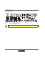
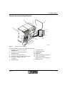
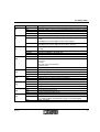
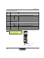
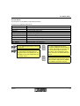
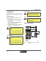
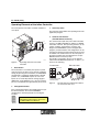
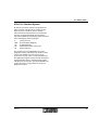
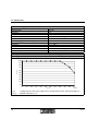
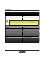
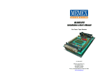
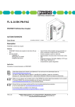
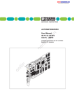
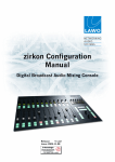
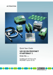
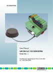
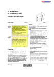
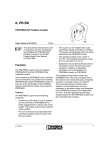
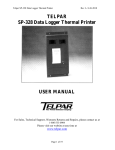
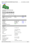
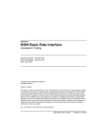
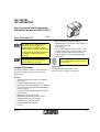
ILC 200 IB ILC 200 IB-PAC Inline Controller with Programming Capabilities According to IEC 61131-3 Data Sheet 5883C04 07/2010 ILC 200 IB and ILC 200 IB-PAC only differ in the scope of supply (see "Ordering Data" on page 20). Their function and technical data are identical. For greater clarity, the Order Designation ILC 200 IB is used throughout this document. This data sheet is only valid in association with the IB IL SYS PRO UM E User Manual, order no. 27 43 04 8. Product Description The Inline Controller is a Remote Field Controller for the Inline installation system with IEC 61131-3 programming. 5 8 8 3 B 0 0 1 – – – – Direct connection of Inline I/O terminals INTERBUS remote bus devices can be connected via branch bus terminal. (as first device) Four 24 V DC inputs (two thereof can be used as 5 V inputs alternatively) and two 24 V DC outputs as high speed I/Os (fast inputs and outputs). Function modules for parameterizing the high speed inputs. For further technical details please refer to the ILC 200 IB UM E user manual, order no. 27 29 72 9. Applications Distributed modular automation control (function units) in machines and systems. Features – – – – – – – – – – Automation and control functions according to IEC 61131-3 Configuring and Programming using the automation software PC WORX 2 or PC WORX 3 Project and program download via INTERBUS or RS-232 interface Preprocessing and application program on the Inline Controller INTERBUS protocol (IEC 61158) Master/slave functionality (system coupler) Complete Generation 4 functionality Comprehensive system diagnostics Firmware download via RS-232 PCP 4.x 5883C04 1 ILC 200 IB (-PAC) Internal Circuit Diagram 2 I1 R D B A 2 4 U S 2 I2 µ P T R R C I4 I3 Q 1 L o c a l b u s I P M S M C 6 8 3 3 2 U M N V R A M Q 2 U L U L F L A S H 2 R A M 2 R e s e t S U P I µ P 7 V 5 V 5 V 5 V 2 4 V S R E 1 R S -4 2 2 In te rfa c e / R S -4 2 2 In te rfa c e R S -4 2 2 In te rfa c e 2 4 V / / R S -4 2 2 In te rfa c e 2 4 V 2 4 V 2 4 V 2 4 V / + 2 4 V (U 1 1 2 + 2 4 V (U ) S M ) 2 5 8 8 3 D 0 0 6 Figure 1 Internal wiring of the terminal points The symbols are explained in the IB IL SYS PRO UM E User Manual. 2 5883C04 ILC 200 IB (-PAC) Connecting and Operating Elements 1 2 1 1 1 0 1 3 9 R E S E T 2 2 C O N F 2 3 3 S T A R T S T O P 3 4 4 R S 2 3 2 4 8 7 5 6 4 3 2 1 Figure 2 Structure of the ILC 200 IB The Inline Controller consists of the following components: 1 Connector 1: remote bus connection 7 (INTERBUS IN) 8 2 Connector 2: remote bus connection 9 (INTERBUS OUT) 10 3 Connector 3: input terminal points 11 4 Connector 4: input and output terminal points 12 5 Connector 5: segment, main and ILC supply 13 6 RS-232 interface 5883C04 5 9 4 5 B 0 0 7 Start/Stop Switch Configuration button RESET button End plate Diagnostics and status indicators FE contact to DIN rail (right housing side, covered here) Electronics base 3 ILC 200 IB (-PAC) Local Diagnostic and Status Indicators 1 3 5 6 B A R D I1 R C T R I3 7 9 F C R U N I2 I4 1 1 2 Figure 3 Des. BA (1) 2 1 4 1 1 2 1 1 1 S Y S F A IL Q 1 Q 2 11 2 1 1 (2) RD (3) TR (4) I1, I2, I3, I4 (5) Q1, Q2 (6) 4 U M U L 1 1 1 8 1 1 0 1 4 U S R D Y /R U N B S A F A IL P F 2 2 2 1 1 2 1 5 5 9 4 5 B 0 1 5 ILC 200 IB with appropriate connectors Color Green LED ON Flashing RC 1 3 1 1 OFF Green LED ON OFF Yellow LED ON OFF Green LED ON OFF: Yellow LED ON OFF Yellow LED ON OFF Meaning Remote bus active Data transmission on INTERBUS active (Status of the higher-level controller board: Run) ID cycle; no data transmission (Status of the higher-level controller board: Active) No data transmission Remote bus check Higher-level controller board is connected Connection to the higher-level controller board interrupted or not yet established Remote bus disabled Outgoing remote bus interface switched off Outgoing remote bus interface not switched off PCP active (transmission) Inline Controller receiving or sending data Inline Controller receiving or sending no data Input status Corresponding input set Corresponding input not set Output status Corresponding output set Corresponding output not set 5883C04 ILC 200 IB (-PAC) Des. FCRUN (7) SYSFAIL (8) Color Green LED ON Flashing OFF Yellow LED ON OFF RDY/RUN Green LED (9) FAIL (10) BSA (11) PF (12) US (13) UM (14) UL (15) ON Flashing OFF Red LED ON OFF Yellow LED ON OFF Yellow LED ON OFF Green LED ON OFF Green LED ON OFF Green LED ON OFF 5883C04 Meaning Field Controller running IEC 61131 runtime system successfully initialized and a program is running IEC 61131 runtime system successfully initialized IEC 61131 runtime system not ready to operate System failure A runtime error has occurred in the program of the IEC 61131 runtime system; as intelligent bus terminal: higher-level bus bus stopped No error as intelligent bus terminal: higher-level bus bus is running Module ready to operate/data transmission active (INTERBUS ready/ running) Submaster in RUN state Submaster in READY or ACTIVE state Controller board not ready to operate/no data transmission Controller failure One of the following errors has occurred: - User error - I/O error - Bus error in the lower-level bus - Controller error None of the above mentioned errors occurred Bus segment aborted At least one bus segment in the lower-level bus disconnected No bus segment in the lower-level bus disconnected Peripheral fault Peripheral fault on a device in the lower-level bus No peripheral fault in the lower-level bus Segment supply Voltage present in segment circuit Voltage not present in segment circuit Main supply Voltage present in main circuit Voltage not present in main circuit ILC supply Supply present (24 V controller supply/ 7.5 V communications power/interface supply, 24 V analog supply) Supply not present 5 ILC 200 IB (-PAC) Terminal Point Assignment 1 1 1 1 1 2 .1 1 .2 2 2 2 .2 3 3 2 .3 4 4 1 .1 1 1 2 .1 1 .2 2 2 2 .2 1 .3 3 3 1 .4 4 4 2 .3 1 .1 1 1 2 .1 1 .2 2 2 2 .2 1 .3 3 3 2 .3 4 2 .4 1 .4 4 1 .5 1 .6 1 , 2 Figure 4 2 .4 5 2 1 .3 1 .4 2 1 .1 2 2 .4 5 6 6 2 .5 5 2 .6 3 , 4 5 8 8 3 B 0 0 4 Terminal point assignment The connectors are supplied with the ILC 200 IB-PAC Inline controller. The connectors are not supplied with the ILC 200 IB Inline controller. Refer to the "Ordering Data" on page 20 for ordering the appropriate connector set. 6 5883C04 ILC 200 IB (-PAC) Incoming and Outgoing Remote Bus Terminal Point Connector 1 1.1 2.1 1.2 2.2 1.3 2.3 1.4, 2.4 Connector 2 1.1 2.1 1.2 2.2 1.3 2.3 1.4, 2.4 Assignment Wire Color/Remark Incoming Remote Bus Receive DO1 DO1 Receive DI1 Send DI1 Send Ground Not used Shield Outgoing Remote Bus DO2 DO2 DI2 DI2 Ground RBST Shield Send Send Receive Receive Wire color in the INTERBUS standard cable: green Wire color in the INTERBUS standard cable: yellow Wire color in the INTERBUS standard cable: pink Wire color in the INTERBUS standard cable: gray Wire color in the INTERBUS standard cable: brown Connected with a capacitor to FE of the potential jumper Wire color in the INTERBUS standard cable: green Wire color in the INTERBUS standard cable: yellow Wire color in the INTERBUS standard cable: pink Wire color in the INTERBUS standard cable: gray Wire color in the INTERBUS standard cable: brown Directly connected to FE of the potential jumper . If the outgoing remote bus interface is not used you must install a jumper (second connector). Terminal points 1.3/2.3 must be jumpered (see Figure 5). B A R D I1 R C T R I3 I2 I4 1 2 1 2 1 2 1 1 1 1 1 1 2 2 2 2 2 2 3 3 3 3 3 3 4 4 4 4 4 4 5 6 5 6 IN T E R B U S IN Figure 5 5883C04 5 8 8 3 C 0 0 9 Jumper position 7 ILC 200 IB (-PAC) Fast Inputs and Outputs Terminal Point Connector 3 1.1 2.1 1.2 2.2 1.3 2.3 1.4 2.4 1.5 2.5 1.6 2.6 Connector 4 1.1 2.1 1.2 2.2 1.3 2.3 1.4 2.4 1.5 2.5 1.6 2.6 Assignment Wire Color/Remark 24 V Input Terminals I1 Input 1 I2 Input 2 24 V (UMAIN) Main circuit (initiator supply) Main circuit (initiator supply) 24 V (UMAIN) SGND Signal ground SGND Signal ground I3 Input 3 I4 Input 4 24 V (UMAIN) Main circuit (initiator supply) Main circuit (initiator supply) 24 V (UMAIN) SGND Signal ground SGND Signal ground 5 V Input Terminals and Output Terminals I1’ I2’ SGND SGND FE FE Q1 Q2 SGND SGND FE FE Input 1 for 5 V (either I1 or I1’ to be used) Input 2 for 5 V (either I2 or I2’ to be used) Signal ground Signal ground Functional earth ground Functional earth ground Output 1 Output 2 Signal ground Signal ground Functional earth ground Functional earth ground The maximum total current flowing through the potential jumpers is 8 A. 8 For further information on the high-speed inputs and outputs please refer to the ILC 200 IB UM E User Manual. 5883C04 ILC 200 IB (-PAC) Function Blocks Function blocks are available for input parameterization. Overview of ILC 200 IB function blocks Function Block DIGITAL_IN DIGITAL_OUT DIO_CTU DIO_CTD DIO_EXT_CTU DIO_EXT_CTD DIO_PPWA DIO_PWM EVENT_INIT GET_EVENT Short description Reads the digital I/O channel Sets the digital I/O channel Up counter with gate function Down counter with gate function Up counter with gate and additional function Down counter with gate and additional function Measures pulse or period length Creates a variable square-wave frequency Links an input with an event task Reads the state of an event input The ILC 200 IB function blocks cannot be instantiated. Each of the four input channels can only be assigned one operating mode for program runtime. The channels are only available for other operating modes after a controller restart. For a more detailed function block description including the technical data for the inputs and outputs in connection with the function blocks (limit frequencies, delay times, gate-controlled rise times) please refer to the ILC 200 IB UM E User Manual. For additional information on programming the function blocks, please refer to the online help of the PC WORX 2 or PC WORX 3 automation software. 5883C04 9 ILC 200 IB (-PAC) Supply Voltages 1 U IN L IN E Figure 6 C O N T R O L 2 1 1 2 2 3 3 4 4 + + + - IL C IL C - U - S M 2 0 0 IB 5 8 8 3 A 0 1 0 Connection example Terminal Assignment Point Connector Power Connector 5 1.1 24 V DC 24 V segment voltage supply (US) 1.2 24 V DC 24 V supply (UILC) 2.1, 2.2 24 V DC (UM) 1.3 LGND 2.3 SGND 1.4, 2.4 FE 10 U 24 V segment main voltage supply (Main Power) Reference potential logic ground Reference potential segment ground Functional earth ground (FE) Wire Color/Remark The supplied voltage is directly routed to the potential jumper. The 7 V communications power (UL) for the ILC and the connected local bus devices is generated from this voltage. The 24 V analog power (UANA) for the local bus devices is also generated. The main voltage is routed to the local bus devices via the potential jumpers. The potential is the reference ground for the communications power. The reference potential is directly led to the potential jumper and is, at the same time, ground reference for the main and segment supply. Functional earth ground must be connected through the voltage supply. The contacts are directly connected to the potential jumper and the FE spring on the bottom of the housing. The terminal is grounded when it is snapped onto a grounded DIN rail. Functional earth ground is only used to discharge interference. 5883C04 ILC 200 IB (-PAC) 24 V Segment supply/ 24 V Main supply 24 V ILC Supply The 24 V ILC supply has protection against polarity reversal and surge voltage. These protective elements are only used to protect the power supply unit. The segment supply and main supply must have the same reference potential. A floating architecture is not possible. 24 V Segment Supply There are several ways of providing the segment voltage at connector 5: 1. You can provide the segment voltage separately at the terminal points 1.1 and 2.3 (GND) (see Figure 6). 2. You can jumper the connections 1.1 and 2.1 (or 2.2) to ensure that the segment circuit is supplied from the main circuit. 3. You can create a switched segment circuit with a switch between terminal points 1.1 and 2.1 (or 2.2). Jumpers Terminals 1.3 and 2.3 on connector 5 can be jumpered if the communications power and the segment power are not to be electrically isolated. Connection Example The 24 V segment supply has protection against polarity reversal and surge voltage. B A R D I1 R C T R I3 F C R U N 1 It does not have short-circuit protection. 2 1 2 1 S Y S F A IL Q 1 I4 Q 2 11 2 U S R D Y /R U N B S A F A IL P F I2 U M U L 1 2 2 2 1 1 1 1 1 1 1 1 1 1 1 2 2 2 2 2 2 2 2 2 2 2 The user must provide short-circuit protection. The rating of the preconnected fuse must be such that the maximum permissible load current is not exceeded. + + 3 3 3 3 3 3 3 3 4 4 4 4 4 4 4 4 4 U 3 IL C - + 3 4 4 - 3 U U S M 24 V Main Power: 5 5 5 5 IN L IN E The 24 V main supply has protection against polarity reversal and surge voltage. 6 6 6 C O N T R O L IL C 2 0 0 IB 6 It does not have short-circuit protection. The user must provide short-circuit protection. The rating of the preconnected fuse must be such that the maximum permissible load current is not exceeded. 5883C04 IN T E R B U S IN Figure 7 IN T E R B U S O U T 5 8 8 3 C 0 0 5 Typical cable connection to the Inline controller 11 ILC 200 IB (-PAC) Operating Elements of the Inline Controller The control panel of the Inline Controller is behind a cover plate. 3 Start/stop switch The start/stop switch defines the operating state of the application program. 4 1 R E S E T C O N F 2 3 3 S T A R T S T O P 3 4 4 R S 2 3 2 4 2 2 2 3 4 5 8 8 3 B 0 0 7 Figure 8 Operating elements of the Inline Controller Serial RS-232 interface (mini-DIN female connector) The serial interface (RS-232) of the Inline Controller connects an IBM-compatible PC with the PC WORX automation software. This operating software can be used to configure, parameterize, program, and diagnose the INTERBUS system. The application program, parameterization, and configuration can be stored on the internal parameterization memory using PC WORX. The serial interface on the front plate of the Inline Controller has been designed as a 6-pos. Mini-DIN female connector (PS/2). The board is connected to the PC via the RS-232 cable PRG CAB MINI DIN (Order No. 27 30 61 1) as shown in the following. F r o n tb le n d e 1 Reset button The reset button is covered by the operator’s panel and can only be set with a pen to prevent accidental setting. By pressing the reset button, the INTERBUS masterboard is completely initialized and re-booted (selftest, etc.). INTERBUS outputs are reset and inputs are not read. All parameter settings (logical addressing, event definitions, etc.) are lost. The boot process is completed after approximately 40 seconds. 2 1 2 4 5 6 T X R X G N R T C T R S -2 3 2 -K a b e l B u c h s e n s e ite D 6 D 5 D S 4 1 2 2 3 4 5 3 2 1 S 6 - p o lig e M in i- D IN B u c h s e (P S /2 ) Figure 9 5 8 8 3 B 0 0 8 RS-232 interface and RS-232 cable for the connection with a PC Configuration button If the configuration button is pressed during start up of the Inline Controller, the current INTERBUS configuration is read and passed on to the higherlevel bus. For further information on the configuration buttons please refer to the ILC 200 IB UM E User Manual. 12 5883C04 ILC 200 IB (-PAC) IEC-61131 Runtime System An IEC 61131 runtime system is integrated in the Inline Controller. This IEC 61131 runtime system allows to process simple as well as complex automation and control functions. The automation functions are programmed with the automation software PC WORX. Programming may be carried out in the following IEC-61131 languages: IL FBD LD OB ST (Instruction List) (Function Block Diagram), (Ladder Diagram), (Sequential Function Chart) and (Structured Text) The program can be modified while the control program is running. The IEC-61131 runtime system can process multiple user tasks which can be processed in a cyclic, time, or event-controlled way. The application program may be stored in the internal parameterization memory. Remanent flags (retain variables) may be stored in an 8 Kbyte NVRAM. The system also offers a large number of safety and diagnostic functions. 5883C04 13 ILC 200 IB (-PAC) Technical Data General Data Order designation Order no. Dimensions Without connectors With connectors Weight Without connectors With connectors 24 V Main Supply/24 V Segment Supply Connection method Recommended cable lengths Voltage continuation Safety measure Surge voltage Polarity reversal ILC 200 IB ILC 200 IB-PAC 27 29 80 0 28 62 28 8 110 mm x 120 mm x 71.5 mm (1.890 x 3.346 x 6.535 in.) 110 mm x 141.1 mm x 71.5 mm (1.890 x 3.346 x 6.535 in.) 320 g 420 g Spring-cage terminals 30 m (98.43 ft.), maximum; routing cables through outdoor areas is not permissible Through potential routing Input protective diodes (can be destroyed by permanent overload) Pulse loads up to 1500 W are short circuited by the input protective diode. Parallel polarity protection diodes; in the event of an error the high current through the diodes causes the preconnected fuse to blow. This 24 V area must be provided with an external fuse. The power supply unit must be able to supply 4 times the nominal current of the external fuse, to ensure that the fuse blows safely in the event of an error. 14 5883C04 ILC 200 IB (-PAC) 24 V Inline Controller Supply Connection method Recommended cable lengths Voltage continuation Safety measure Surge voltage Polarity reversal Spring-cage terminals 30 m (98.43 ft.), maximum; routing cables through outdoor areas is not permissible Through potential routing Input protective diodes (can be destroyed by permanent overload) Pulse loads up to 1500 W are short circuited by the input protective diode. Serial diode in the lead path of the power supply unit; in the event of an error only a low current flows. In the event of an error, the fuse in the external power supply unit does not trip. Ensure protection of 2 A by fuses through the external power supply unit. This 24 V area must be provided with an external fuse. The power supply unit must be able to supply 4 times the nominal current of the external fuse, to ensure that the fuse blows safely in the event of an error. Nominal value Tolerance Ripple Permissible range Minimum current consumption at nominal voltage Maximum current consumption at nominal voltage 5883C04 24 V DC -15 % / +20 % (acc. to EN 61131-2/IEC 61131-2) ±5 % 19.2 V to 30 V 153 mA DC (At no-load operation, i.e., incoming remote bus connected, no local bus devices are connected, bus inactive) 2.4 A DC 15 ILC 200 IB (-PAC) 24 V Module Supply - Communications Power (Potential Jumper) Nominal value Tolerance Ripple Maximum output current Safety measure - Analog Supply (Potential Jumper) Nominal value Tolerance Ripple Maximum output current Safety measure 7.5 V DC ±5 % ±1.5 % 2 A DC (observe derating) Electronic short-circuit protection 24 V DC -15 % / +20 % ±5 % 0.5 A DC (observe derating) Electronic short-circuit protection Derating of the Communications Power and the Analog Terminal Supply - I/O Supply Current Load at the Bus Terminal: 8 A, Maximum 1 0 0 9 0 8 0 7 0 P [% ] 6 0 5 0 4 0 3 0 2 0 1 0 0 0 5 1 0 1 5 2 0 2 5 3 0 T P [%] TA [°C] 16 U [° C ] 3 5 4 0 4 5 5 0 5 5 5 5 2 0 A 0 1 2 Loading capacity of the power supply unit for communications power and analog supply in % Ambient temperature in °C 5883C04 ILC 200 IB (-PAC) Safety Equipment Surge voltage (segment supply/main supply/bus terminal supply) Polarity reversal (segment supply/main supply) Polarity reversal (bus terminal supply) INTERBUS Generation 4 features Number of I/O points Number of devices per configuration Number of remote bus devices Number of PCP devices Number of remote bus levels Bus Interface Higher-Level Bus Module ID Number of process data words Number of PCP words Operating mode Electrical Isolation 5883C04 Input protective diodes (can be destroyed by permanent overload) Pulse loads up to 1500 W are short circuited by the input protective diode. Parallel polarity protection diodes; in the event of an error the high current through the diodes causes the preconnected fuse to blow. Serial diode in the lead path of the power supply unit; in the event of an error only a low current flows. In the event of an error, the fuse in the external power supply unit does not trip. Ensure protection of 2 A by fuses through the external power supply unit. 4096, maximum 512, maximum 254, maximum 62, maximum 16, maximum Variable: 3dec, 232dec, 233dec, 235 dec (default: 233dec) Configurable: = 0 words up to 10 words (default: 0 words) Configurable: 0, 1, 2 or 4 words (default: 4 words) PCP and process data operation with the higher-level INTERBUS controller board On both interfaces 17 ILC 200 IB (-PAC) Bus Interface Lower-Level Bus Interface Inline local bus Electrical Isolation No Number of devices (Number of devices that can be connected) Limitation through software 63, maximum Limitation through current consumption from - Communications power UL 2 A DC 0.5 A DC - Analog supply UANA Observe the current consumption of the modules Observe the logic current consumption of each device when configuring an Inline station. This information is given in every module-specific data sheet. The current consumption can differ depending on the individual module. The permissible number of devices that can be connected depends on the specific station structure. Diagnostic Interface Connection method Interface type Transmission rate Electrical Isolation 6-pos. MINI-DIN female connector (PS/2) RS-232 9600 baud No Optical Diagnostics Higher-level INTERBUS Voltage Supply IEC -61131 Runtime System Lower-level INTERBUS BA, RC, RD, TR UL, UM, US FCRUN, SYSFAIL RDY/RUN, BSA, FAIL, PF IEC 61131 Runtime System Speed Shortest cycle time (for cycle task) Program memory capacity Number of control tasks Memory for retentive data 1.3 ms for instructions (typical) 5 ms 384 kbytes, 32 kbytes instruction in IL, typical 8 control tasks 8 kbytes NVRAM 18 5883C04 ILC 200 IB (-PAC) Ambient Conditions Degree of protection Temperature (according to EN 60204-1/IEC 60204-1) Operation Storage and transport: Humidity (according to EN 60204-1/IEC 60204-1) Storage and operation: Air pressure Operation Vibration Conformance With EMC Directive 98/37/EG Noise Immunity Test According to EN 61000-6-2 Electrostatic discharge (ESD) EN 61000-4-2 IEC 61000-4-2 Fast transients (burst) Conducted interference Noise emission of housing -25°C to 55°C (-13°F to 131°F) -25°C to +75°C (-13°F to 167°F) 75 % on the average, 85 % occasionally (EN 60204-1/IEC 60204-1); no condensation 70 kPa to 108 kPa (up to 3000 m [9843 ft.] above sea level) 66 kPa to 108 kPa (up to 3500 m [11483 ft.] above sea level) 2g, criterion 1 acc. to EN 60068-2-6/IEC 60068-2-6 Storage and transport Electromagnetic fields IP20 (EN 60529/IEC 60529) EN 61000-4-3 IEC 61000-4-3 EN 61000-4-4/ IEC 61000-4-4 EN 61000-4-6 IEC 61000-4-6 EN 55011 Criterion B 6 kV contact discharge 8 kV air discharge Criterion A Field strength: 8 V/m Criterion B Supply lines: 2 kV Signal/data lines: 2 kV Criterion A Test voltage 10 V Class A Portable radiotelephone equipment (P 2 W) must not be operated any closer than 2 m (6.56 ft). There should be no strong radio transmitters or ISM (industrial scientific and medical) devices in the vicinity. 5883C04 19 ILC 200 IB (-PAC) Ordering Data Ordering Data for Hardware and Software Description Inline Controller; including connectors and labeling fields Inline Controller Order Designation ILC 200 IB-PAC Order No. 28 62 28 8 ILC 200 IB 27 29 80 0 The listed connector set is needed for the complete fitting of the ILC 200 IB controller. Connector set for the Inline Controller RS-232 cable IBS PC WORX 2 automation software (license-free version) Automation softwarePC WORX 3 DEMO ILC IB-PLSET PRG CAB MINI DIN IBS PCWORX 27 29 62 2 27 30 61 1 27 29 35 0 PC WORX 3 DEMO 27 30 96 7 The automation software IBS PC WORX 2 and PC WORX 3 is available with different licence levels. For the order number of the licence you need, please refer to the current "INTERBUS & AUTOMATION" catalog by Phoenix Contact. 20 5883C04 ILC 200 IB (-PAC) Ordering Data for Documentation Description Configuring and Installing INTERBUS Inline User Manual Quick Start Guide IBS PC WORX 2.0 PC WORX 2 User Manual (binder) The binder includes the following documents: SYSTEM WORX Reference Manual PROGRAM WORX User Manual PROGRAM WORX User Manual Functions and Function Blocks PROGRAM WORX User Manual Machine Sequential Function Chart - MSFC PC WORX 3.0 Quick Start Guide Diagnostics Guide Order Designation IB IL SYS PRO UM E IBS PCWORX 2.0 QS UM E IBS PCWORX UM E Order No. 27 43 04 8 90 00 05 3 27 47 55 2 IBS SYSTEM WORX 2.0 UM E IBS PROGRAM WORX 2.0 UM E IBS PROGRAM WORX 2.0 FUB UM E IBS MACHINE WORX UM E 90 00 04 7 90 00 04 9 90 00 05 1 PC WORX 3 QS UM E IBS SYS DIAG DSC UM E 28 28 72 7 27 47 29 3 93 55 56 5 Technical modifications reserved Make sure you always use the latest documentation. This is available to be downloaded at www.phoenixcontact.com. © Phoenix Contact 07/2010 Phoenix Contact GmbH & Co. KG Flachsmarktstr. 8 32825 Blomberg Germany + 49 - (0) 52 35 - 3-00 + 49 - (0) 52 35 - 3-4 12 00 www.phoenixcontact.com 21 5883C04