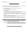
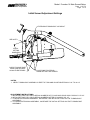
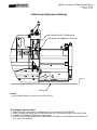
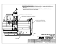
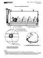
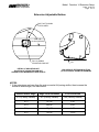
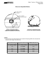
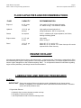
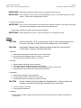
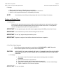
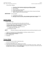
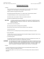
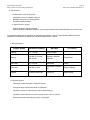
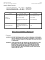
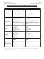
1
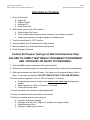
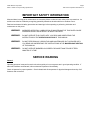
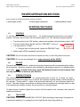
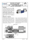
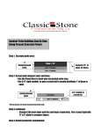
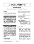
PAVER OPERATION MANUAL MODEL 1550-D Paver Serial Number _ ______________________________ Paver Specification Number _ ______________________________ Engine Serial Number _ ______________________________ SOLD & SERVICED BY: TABLE OF CONTENTS SECTION ITEM PAGE 1.0 Daily Start-up Checklist ................................................................................................ 3 2.0 Important Safety Information ....................................................................................... 4 3.0 Service Warning ............................................................................................................ 4 4.0 Starting the Paver ........................................................................................................ 4 5.0 Screed Operation .......................................................................................................... 7 5.1 Screed Heating System ......................................................................................... 7 5.2 Crowning the Screed .............................................................................................. 7 5.3 Setting the Extensions ........................................................................................... 9 5.4 Before you Pave ...................................................................................................... 10 5.5 Null your Screed ..................................................................................................... 10 Fluids & Capacities ....................................................................................................... 11 Engine Coolant ....................................................................................................... 11 LUBRICATION & SERVICE PROCEDURES ................................................................ 11 7.1 Air Filters ................................................................................................................. 11 7.2 Battery ..................................................................................................................... 12 7.3 Engine & Engine Filters ......................................................................................... 13 7.4 Hydraulic System .................................................................................................... 14 7.5 Conveyor System ................................................................................................... 14 7.6 Troubleshooting Guide .......................................................................................... 15 7.7 Component Removal & Installation ...................................................................... 17 7.8 Recommended Preventive Maintenance Intervals .............................................. 18 Warranty ......................................................................................................................... 20 6.0 6.1 7.0 8.0 Calder Brothers Corporation Model: 1550-D Conveyor Feeding Asphalt Paver Page 3 1550-C Paver Operation Manual Rev 1.3 Daily Start-up Checklist 1. Check Fluid Levels: a. b. c. d. Engine Oil Engine Coolant Hydraulic Oil Wash Down fluid 2. With the key switch in the “ON” position: a. Check Engine Fuel Level b. Turn on wash down pump and verify operation, turn off when complete. c. Verify proper operation of engine gauges or indicator lights. 3. Turn Key switch back to “OFF” position. 4. Remove asphalt from all mechanical moving surfaces 5. Remove asphalt from all screed burner heating areas 6. Check Propane Tank level. Perform All Propane Testing In A Well Ventilated Area Only! FAILURE TO COMPLY MAY RESULT IN DAMAGE TO EQUIPMENT AND / OR INJURY OR DEATH TO PERSONNEL. 7. Verify that ALL propane valves are in the closed position. 8. Pressurize the propane system by opening the master valve located on the propane tank. 9. With system pressurized, listen for leaks. Run hand over all propane fittings to feel for leaks. If any leaks are detected, DO NOT OPERATE UNTIL THEY ARE REPAIRED! 10. Check pressure regulator is set to 4 PSI on Freedom™ IV Screed. a. If regulated pressure is too high, open main screed valve only allowing gas to escape. b. Adjust regulator to 4 PSI on Freedom™ IV Screed. c. Close main screed valve. 11. Close the master valve located on the propane tank. 12. Verify & if necessary follow procedure to set screed. 13. Perform a machine walk around looking for: a. b. c. d. Any signs of physical damage Any signs of a leak, (fuel, engine oil, hydraulic oil, engine coolant) Welded steel junctions Hydraulic cylinder pins all secure Calder Brothers Corporation Model: 1550-D Conveyor Feeding Asphalt Paver Page 4 1550-C Paver Operation Manual Rev 1.3 IMPORTANT SAFETY INFORMATION Most accidents involving paver maintenance are caused by failure to observe basic safety rules or precautions. An accident can often be avoided by recognizing potentially hazardous situations before an accident occurs. Read and understand all safety precautions and warnings, before operating or performing lubrication and maintenance on this paver. WARNING: IMPROPER OPERATION, LUBRICATION OR MAINTENANCE OF THIS PAVER CAN BE DANGEROUS AND COULD RESULT IN INJURY OR DEATH. WARNING: DO NOT OPERATE THIS PAVER UNTIL YOU READ AND UNDERSTAND THE INSTRUCTIONS IN THE OPERATION SECTION OF THIS MANUAL. WARNING: DO NOT PERFORM ANY LUBRICATION AND MAINTENANCE ON THIS PAVER UNTIL YOU READ AND UNDERSTAND THE INSTRUCTIONS IN THE MAINTENANCE SECTION OF THIS MANUAL. WARNING: DO NOT OPERATE BURNERS ON SCREED FOR MORE THAN TEN OR FIFTEEN MINUTES AT A TIME. SERVICE WARNING General Operating personnel must perform service checks regularly to be sure systems are in good operating condition. If abnormal conditions are detected, inform maintenance personnel immediately. Check all systems for proper operation. Check chassis and all components for physical damage and security of all fasteners and connectors. Calder Brothers Corporation Model: 1550-D Conveyor Feeding Asphalt Paver Page 5 1550-C Paver Operation Manual Rev 1.3 PAVER OPERATION SECTION Prior to starting the following procedures must be completed. 1. Check engine oil level 2. Check engine coolant level 3. Check hydraulic oil level STARTING THE PAVER 1.0 STARTING To start the paver first check to make sure t he forward and reverse levers are in the neutral position. The paver will not start if the red indicator light is not “ON” indicating a neutral position. Turn key switch to the “ON” position, adjust steer handles until red indicator light is “ON” Turn key switch back to the left, position “PRE-HEAT” count to 5 If Glow Plug Turn key switch to “START”. If engine does not start quickly, repeat the PRE-HEAT step equipped Adjust engine RPM as needed for smooth idle. CAUTION: Do not Pre-heat more than 5 seconds at a time, or Glow Plug failure will occur. CAUTION: Do not use any starting fluid, or engine warranty will be VOID!!!! 2.0 DRIVING The paver will move forward by pushing both levers forward and will move backwards by pulling the levers back. Steering a course is acco mplished by adjusting the speed of one handle relative to the other. HINT - to make driving easy, push both handles forward to desired speed, then use only one handle to fine-tune your direction. 3.0 STEERING TENSION The steer handles can be adjusted for operator preference on tensi on, (or drag). In a loose position the handles will spring return to neutral, this requires constant pressure on the handles by the operator. Tension can be added to the point were the handl es are locked and cannot be moved. The ideal setting is somewhere in-between were the handles have enough tension to stay in the position the operator chooses, but not so stiff as to produce fatigue. To adjust tension: loosen or tighten the nut locat ed at the center of the aluminum discs were the handles are attached. 4.0 TWO SPEED CAUTION: INJURY/OR DAMAGE MAY OCCUR: When switching to high range, bring paver to a stop before switching. To engage from low to high flip the High range switch up. Calder Brothers Corporation Model: 1550-D Conveyor Feeding Asphalt Paver Page 6 1550-C Paver Operation Manual Rev 1.3 MATERIAL FEED OPERATION The 1550-D and 1500-C allow you to configure the auger and conveyor operation of the paver for both an Automatic mode and a Manual mode. Use the automatic mode whenever possible to increase the useful life of the f eed augers, and to maintain a more co nsistent “Head of Material” in front of the screed. In either mode the lower selector switch can be set to “IN” for reverse material flow. SETUP Each side of the paver must be set independently. AUTOMATIC FEED OPERATION MANUAL FEED OPERATION 1.0 Go to the LH operators station 1.0 Go to the LH operators station 2.0 Locate the AUTO – MAN switch labeled: 2.0 Locate the AUTO – MAN switch labeled: 3.0 Set the switch to “AUTO” 3.0 Set the switch to “MAN” 4.0 Locate the CONV & AUG switches labeled: 4.0 Locate the CONV & AUG switches labeled: 5.0 Set the AUG switch to “OUT” 5.0 Set the AUG switch to “OUT” 6.0 Follow the dotted line and set the CONV switch to the “locked” setting. 6.0 Follow the dotted line and set the CONV switch to the “locked” setting. 7.0 To control size of the head of material: 7.0 To control size of the head of material set the AUG switch to OUT or OFF as desired. 7.1 1550-D – Adjust the control knob to #7 7.2 1500-C – Adjust height of switch by end gate. Calder Brothers Corporation Model: 1550-D Conveyor Feeding Asphalt Paver Page 7 1550-C Paver Operation Manual Rev 1.3 SCREED HEATING SYSTEM The new Freedom™ IV Screed™ has one burner in each extension and two main screed burners. The proper way to light the burner system is the following procedure. 1. Make sure all shutoff valves are in the off position and lighting wand is off. 2. Fully extend the extensions. 3. Turn on gas at tank, and set gauge pressure at 4 p.s.i. 4. Ignite the lighting wand. 5. Use the lighting wand to open the flap style burner lighting access door towards the bottom inboard zone of the LEFT HAND screed extension to ignite the burner. 6. Turn on the gas to the LEFT HAND extension. Repeat step 5 & 6 for right hand extension. 7. The extension burners will have changed from a hissing noise to a roaring noise confirming ignition. 8. After extension burners are ignited, position the lighting wand at the opening found on the back side of the LEFT HAND main screed burner. 9. Turn on gas to the main screed. After ignition of the LEFT HAND main burner, quickly reposition the lighting wand and ignite the right hand main burners the same as the left. Only use burners for 10 - 15 minutes at any given time. Damage to screed plate will occur. WARNING: NEVER USE SYSTEM WITHOUT DIRECT CONSTANT SUPERVISION PERSONAL INJURY OR DEATH MAY RESULT. WARNING: EXCESS GAS ACCUMULATING BEFORE LIGHTING BURNERS MAY CAUSE AN EXPLOSION RESULTING IN PERSONAL INJURY OR DEATH. MAULDIN R PAVING PRODUCTS Model: Freedom 14 Main Screed Setup Date: 11-07-12 Page: 1 of 2 Calder Brothers Corporation Initial Screed Adjustment Settings EXTENSION TURNBUCKLE LOCK BOLT SEE NOTE 1 INITIAL SETTING DIMENSION CHECK TO MAKE SURE THERE ARE NO GAPS ALONG THESE EDGES. LOCATIONS FOR STRING WHEN SETTING THE SCREED. NOTES: 1. VERIFY TURNBUCKLE ASSEMBLY IS FREE TO TURN AND ADJUSTABLE FROM 15-1/4" TO 16-1/4" ADJUSTMENT INSTRUCTIONS: 1. INITIAL SETTING FOR 1550-D SERIAL NUMBERS UP TO AND INCLUDING XXX-XXXXX-XX: 15-3/4" 2. INITIAL SETTING FOR 1550-D SERIAL NUMBERS AFTER XXX-XXXXX-XX: 16" 3. TO RAISE EXTENSION ASSEMBLY, DECREASE THE INITIAL SETTING ON THE TURNBUCKLE ASSEMBLY. 4. TO LOWER EXTENSION ASSEMBLY, INCREASE THE INITIAL SETTING ON THE TURNBUCKLE ASSEMBLY. MAULDIN Model: Freedom 14 Main Screed Setup R PAVING PRODUCTS Date: 11-07-12 Page: 2 of 2 Calder Brothers Corporation Initial Screed Adjustment Settings EXTENSION SLOPE TURNBUCKLE EXTENSION TURNBUCKLE LOCK BOLT STRING NOTES: 1. POSITION EXTENSION AT HALF WAY OUT POSITION. ADJUSTMENT INSTRUCTIONS: 1. RUN BOTH LEFT AND RIGHT EXTENSION OUT TO THE HALF OUT POSITION. 2. USE A STRING AND ALIGN WITH TRAILING EDGE OF EXTENSION SCREED PLATE BOTTOM. 3. LOOSEN EXTENSION TURNBUCKLE LOCK BOLT. 4. ADJUST THE EXTENSTION SLOPE TURNBUCKLE TO MAKE THE EXTENSION SCREED PLATE FLAT WITH THE STRING. ADJUSTMENT INSTRUCTIONS: 1. TO RAISE EXTENSION ASSEMBLY, DECREASE THE 16" DIMENSION ON THE TURNBUCKLE ASSEMBLY. 2. TO LOWER EXTENSION ASSEMBLY, INCREASE THE 16" DIMENSION ON THE TURNBUCKLE ASSEMBLY. EXTENSION TURNBUCKLE LOCK BOLT VERIFY TURNBUCKLE ASSEMBLY IS FREE TO TURN AND ADJUSTABLE FROM 15-3/4" TO 16-1/4". 16.000 INITIAL SETTING DIMENSION CHECK TO MAKE SURE THERE ARE NO GAPS ALONG THESE EDGES. CHECK TO MAKE SURE THERE ARE NO GAPS ALONG THESE EDGES. DRAWN: LOCATIONS FOR STRING WHEN SETTING THE SCREED. SCREED SETTING INSTRUCTIONS PAGE 1 OF 2 W D Calder 05-15-12 W D Calder 05-15-12 ENGINEER: D M Calder 05-15-12 CAD FILE: 111-209000.slddrw 02-01-11 MAULDIN R PAVING PRODUCTS TITLE: CHECKED: CAD MODEL NO.: FREEDOM FOURTEEN S209 FINAL ASSEMBLY 111-209000 MODEL S209 SHEET NO.: S209-000-03 ADJUSTMENT INSTRUCTIONS: 1. RUN BOTH LEFT AND RIGHT EXTENSION OUT TO THE HALF OUT POSITION. 2. USE A STRING AND ALIGN WITH TRAILING EDGE OF EXTENSION SCREED PLATE BOTTOM. 3. LOOSEN EXTENSION TURNBUCKLE LOCK BOLT. 4. ADJUST THE EXTENSTION SLOPE TURNBUCKLE TO MAKE THE EXTENSION SCREED PLATE FLAT WITH THE STRING. EXTENSION SLOPE TURNBUCKLE EXTENSION TURNBUCKLE LOCK BOLT POSITION EXTENSION AT HALF WAY OUT POSITION. SCREED SETTING INSTRUCTIONS PAGE 2 OF 2 MAULDIN R PAVING PRODUCTS STRING DRAWN: W D Calder 05-15-12 W D Calder 05-15-12 ENGINEER: D M Calder 05-15-12 CAD FILE: 111-209000.slddrw 02-01-11 TITLE: CHECKED: CAD MODEL NO.: FREEDOM FOURTEEN S209 FINAL ASSEMBLY 111-209000 MODEL S209 SHEET NO.: S209-000-04 MAULDIN Model: Freedom 14 Extension Setup R PAVING PRODUCTS Date: 01-03-13 Page: 1 of 3 Calder Brothers Corporation Extension Adjustable Bottom 1/2-13, 1.5" LONG BOLT WITH LOCK WASHER. HINGED EXTENSION SCREEDING PLATE, P/N 112-209830. FACTORY SETTING FOR BOLT ON CAM NUT IS IN THE HORIZONTAL POSITION (OR 3:00 O'CLOCK POSITION). P/N 113-209800 ADJUSTING CAM NUT. 4.0° END VIEW OF EXTENSION BOTTOM (ATTACK ANGLE SHOWN IS FACTORY DEFAULT) DETAIL OF ADJUSTING CAM NUT (POSITION OF ADJUSTING CAM NUT SHOWN IS FACTORY DEFAULT) NOTES: 1. Extensions are factory shipped with P/N 113-209801 non-adustable cam nut. 2. If adjusting the attack angle of the extension screeding plate is required, replace P/N 113-209801 with P/N 113-209800 adjusting cam nut. See the following two (2) pages for instructions to raise or lower the extension screeding plate profile to obtain seemless mat paving performance. MAULDIN Model: Freedom 14 Extension Setup R PAVING PRODUCTS Date: 01-03-13 Page: 2 of 3 Calder Brothers Corporation Extension Adjustable Bottom BOLT NOT SHOWN FOR CLARITY. 75.0° UP (12:30 POSITION) P/N 113-209800 ADJUSTING CAM NUT. DETAIL OF ADJUSTING NUT (POSITION OF ADJUSTING CAM NUT SHOWN IS FOR MAXIMUM ATTACK ANGLE) 6.0° END VIEW OF EXTENSION BOTTOM (ATTACK ANGLE SHOWN IS MAXIMUM) NOTES: 1. If the extensions are lower than the main screed at full paving widths, then increase the extension attack angle, see table below. Desired Attack Angle Angle from Horizontal O'Clock Position 4.0 (Factory Default) 90 (Factory Default) 3:00 (Factory Default) 4.5 15 UP 2:30 5.0 30 UP 2:00 5.5 45 UP 1:30 6.0 75 UP 12:30 MAULDIN Model: Freedom 14 Extension Setup R PAVING PRODUCTS Date: 01-03-13 Page: 3 of 3 Calder Brothers Corporation Extension Adjustable Bottom BOLT NOT SHOWN FOR CLARITY. P/N 113-209800 ADJUSTING CAM NUT. 75.0° DOWN (5:30 POSITION) 2.0° DETAIL OF ADJUSTING CAM NUT (POSITION OF ADJUSTING CAM NUT SHOWN IS FOR MINIMUM ATTACK ANGLE) END VIEW OF EXTENSION BOTTOM (ATTACK ANGLE SHOWN IS MINIMUM) NOTES: 1. If the extensions are higher than the main screed at full paving widths, then decrease the extension attack angle, see table below. Desired Attack Angle Angle from Horizontal O'Clock Position 4.0 (Factory Default) 90 (Factory Default) 3:00 (Factory Default) 3.5 15 DOWN 3:30 3.0 30 DOWN 4:00 2.5 45 DOWN 4:30 2.0 75 DOWN 5:30 Calder Brothers Corporation Model: 1550-C Conveyor Feeding Asphalt Paver Page 11 1550-C Paver Operation Manual Rev 1.3 FLUID CAPACITIES AND RECOMMENDATIONS FLUID CAPACITY RECOMMENDATION Engine oil 8 U.S. quarts 7.5 liters High quality CC/CD multi-grade lubricating oil. Above 14 deg. F use 15W40 or 20W40. Hydraulic 15.5 U.S. gal. 60 liters High quality anti-wear hydraulic oil (Original equipment, Gulf C-3 torque fluid). Grease As required N.G.L.I. consistency #2, high temperature, anti-friction, bearing lubricating grease. Engine coolant 2.1 U.S. gal. 8 liters High quality Above 14 deg. F Diesel 12.5 U.S. gal. 47 liters Above 40°, (5° C), use No. 2-D. Below 40°, (5° C), use No. 1-D. Power loss up to 4% can be expected due to lower viscosity ENGINE COOLANT All engines are shipped from the factory with proper engine coolant and levels. Customers are responsible for filling and maintaining the engine's cooling system s. The use of improper coolant mixtur es in diesel engines can result in serious engine damage due to liner erosion and pitting. Refer to the Operator's Manual for information regarding engine coolant (antifreeze), and change interval recommendations. LUBRICATION AND SERVICE PROCEDURES Air Filters IMPORTANT: Service the engine air filters only when the need is indicated by the air cleaner service indicator, (if equipped), or in accordance with the preventative maintenance decal. Excessive service will cause premature wear. 1. Engine Main Element a. Unbuckle clips to remove element container end cap. b. Pull gently to remove main element. c. Use compressed air with an element-cleaning nozzle Calder Brothers Corporation Model: 1550-C Conveyor Feeding Asphalt Paver Page 12 1550-C Paver Operation Manual Rev 1.3 IMPORTANT: Main element should be replaced after six cleanings or 500 hours use. IMPORTANT: Do not attempt to clean element using a standard air nozzle. Do not strike element on a hard surface. Either action will damage the element. 2. Engine Safety Element IMPORTANT: Do not remove safety element under heavy dust or blowing conditions (in the field). Even slight amounts of dust entering the engine can lead to premature wear. Inspect safety element for contamination and physical damage. IMPORTANT: When safety element is dirty, it should be replaced. Do not attempt to clean. Battery CAUTION: BATTERY ELECTROLYTE IS A CAUSTIC ACID. KEEP IT AWAY FROM SKIN AND EYES. IF CONTACT OCCURS, FLUSH THE AFFECTED AREA WITH LOTS OF WATER. CAUTION: DISCONNECT GROUND CABLE FROM THE NEGATIVE BATTERY POST BEFORE ATTEMPTING TO SERVICE OR REMOVE BATTERY. 1. Removal a. Open engine compartment, locate battery to your near left side. b. Disconnect ground (negative) cable from battery (-) terminal. c. Disconnect positive cable from battery (+) terminal. 2. Cleaning a. b. c. d. Remove battery, following correct procedures. Thoroughly clean terminals with a battery-cleaning tool. Mix a paste solution of baking soda and water and apply to battery and terminals. Rinse battery and paver area near battery liberally with water. 3. Installation a. Clean battery, following correct procedures. b. Be certain battery area is clean and clear of debris. c. Install battery and connect positive (+) cable to terminal. CAUTION: DO NOT CONNECT NEGATIVE (GROUND) TERMINAL FIRST. ARCING CAN OCCUR, POSSIBLY CAUSING SEVERE BURNS AND/OR BATTERY EXPLOSION. d. Connect negative (-) terminal. e. Close engine compartment. 4. Charging a. Connect charger leads to proper battery terminals then proceed according to charger manufacturer's instructions. Calder Brothers Corporation Model: 1550-C Conveyor Feeding Asphalt Paver Page 13 1550-C Paver Operation Manual Rev 1.3 5. Storage a. Remove and clean battery, following correct procedures. b. Bring battery to full charge, following charger manufacturer's instructions. c. Store in a cool dry place where there is no possibility of freezing. Check battery every 30 days during storage and return to full charge if necessary. NOTE: Engine and Engine Filters 1. Initial Break-In Proper break-in procedures are a must to realize maximum engine power output and longest engine life. Engine should show noticeable power gain through the first 30 hours service. Power gain will continue until approximately 200 hours if properly broken-in. IMPORTANT: Do not operate engine above 3/4 throttle, (approximately 2100 RPM), for the first 25 hours. IMPORTANT: Use full throttle only for short intervals during the first 25 hours. IMPORTANT: Do not "lug" engine during the break-in period. IMPORTANT: Replace the original oil and oil filters after the first 20 hours of operation. 2. Fuel Filter / Water Separator i. ii. The fuel filter and water separator is a combined unit, PLEASE NOTE it is NOT disposable. There is also a separate in-line fuel pre-filter which is disposable. BOTH DIESEL FUEL AND GASOLINE ARE HIGHLY FLAMMABLE AND EXPLOSIVE UNDER CERTAIN CONDITIONS. DO NOT SMOKE OR ALLOW SPARKS OR OPEN FLAME WHEN HANDLING. a. To Change: CAUTION: 1. Stop engine. Wait 15 minutes for engine and surrounding parts to cool before proceeding. 2. Unscrew and discard fuel and sediment. 3. Clean bowl thoroughly and fill cleaned bowl with clean fuel. 4. Lightly coat the seal ring with oil, then screw on filter/separator until seal meets flange. 5. Tighten an additional 1/2 to 3/4 turns by hand. IMPORTANT: Do not over tighten. Calder Brothers Corporation Model: 1550-C Conveyor Feeding Asphalt Paver Page 14 1550-C Paver Operation Manual Rev 1.3 b. Oil and Filter Changing: 1. 2. 3. 4. 5. 6. 7. Stop engine. Wait 15 minutes or engine oil to cool before proceeding. On the hopper side, remove drain plug and position capturing bucket. Drain crankcase. Unscrew and discard existing filters. Fill new elements with fresh oil. Lightly coat the seal rings with oil, and then screw on filters until seals meet flanges. Tighten an additional 1/2 to 3/4 turns by hand. IMPORTANT: Do not over tighten. 8. Fill crankcase to correct level. 9. Start engine and run at low idle. Have an assistant visually check seal areas for leaks. 10. Stop engine. Wait a few minutes, and then check engine oil level once again. Hydraulic System 1. Hydraulic Fluid Change a. b. c. d. e. Stop engine. Allow system pressure to drop and remove filler cap. Remove suction hose and drain into appropriate container for disposal. Remove hydraulic filter. Replace filter element and reinstall. RETRACT ALL HYDRAULIC CYLINDERS! Replace fluid to approximately 1" from top of reservoir. Operate paver and recheck level. f. Check visually for oil leaks. NOTE: 1. 2. 3. 4. 5. Each paver should be thoroughly inspected after each use and during maintenance cycle for: Tightness of mounting bolts and attaching hardware on bearings, couplings, frame, etc. Leaks, cracks and loose electrical and fluid fittings. Malfunctioning indicators or controls. Worn or damaged tires. Cleanliness. Conveyor System Conveyor drive system should be inspected annually. 1. Check for worn sprockets and chain. 2. Check keys and keyways for wear. Replace keys if needed. 3. Tighten large conveyor chains with slack adjustors mounted to the underside of the conveyor. Tighten until the chains pull up to within 7” – 8” of the underside of the conveyor deck. Measurement should be made from the peak of the arc in the chains. Do not over tighten. Calder Brothers Corporation Model: 1550-C Conveyor Feeding Asphalt Paver Page 15 1550-C Paver Operation Manual Rev 1.3 TROUBLESHOOTING 1. General Proper troubleshooting begins with an organized approach to the problem at hand. Begin with investigation of the most probable cause, following the guidelines below. Study the problem thoroughly before taking action: Did warning signs precede the problem? If so, what were they? What would they indicate? Is scheduled maintenance current on all parts and systems involved? Has similar trouble occurred before? What action was taken at that time? Can engine be operated without further damage? CAUTION: IF RUNNING INSPECTION MUST BE MADE, GET ASSISTANCE. OPERATOR SHOULD REMAIN ON PAVER THROUGHOUT INSPECTION. MAKE SURE TRANSMISSION IS IN NEUTRAL POSITION. Check the most convenient things first. Don't begin major work before checking all other possibilities. Reconsider all known facts and clues before proceeding to more in-depth work. Correct the basic cause. Remember, failure of a certain part may be caused by malfunction of another part or system. 2. Use of Schematics The Parts & Service manual incorporates electrical and hydraulic diagrams formatted for ease of use by maintenance and for the training of personnel. 3. Troubleshooting chart The troubleshooting chart lists problems that might be encountered in the operation of the vehicle. The remedies listed may direct the repairman to a possible faulty component. WARNING: THE TROUBLESHOOTING CHART AND PROCEDURES OUTLINED IN THIS SECTION SHOULD NOT BE ATTEMPTED BY OTHER THAN EXPERIENCED MECHANICS OR PERSONNEL UNDER THE DIRECT SUPERVISION OF AN EXPERIENCED MECHANIC. FAILURE TO COMPLY MAY RESULT IN DAMAGE TO EQUIPMENT AND/OR INJURY OR DEATH TO PERSONNEL. A. Engine For engine troubleshooting see charts indicating faults and recommended repair procedures, refer to Manufacturer's Operation and Maintenance Manual. If your particular problem is not covered or you are unsure of what steps to take, contact your dealer for assistance. Calder Brothers Corporation Model: 1550-C Conveyor Feeding Asphalt Paver Page 16 1550-C Paver Operation Manual Rev 1.3 B. Transmission 1. Vehicle fails to move under power. Inadequate oil level in hydraulic reservoir. Damaged wiring loom to steering station Driveline mechanical failure 2. Vehicle moves in neutral. Steering levers are actually engaged Steering calibration adjustment required, (must be performed by authorized MAULDIN service technician) For detailed troubleshooting information on hydrostatic transmission, refer to Trouble Shooting Manual, Rexroth Hydrostatic Transmissions, available from a Rexroth representative or dealer. C. Electrical System Engine Status Voltmeter Reading Indicates To Correct Running 13.5 - 14 Volts Normal Condition Running Less than 13.5 or more than 14 Volts Alternator or Regulator Malfunction Contact Dealer Won’t Start 12 - 12.5 Volts Weak battery Charge Won’t Start Less than 12 Volts Weak battery or Defective Cell Charge or Replace Stopped Excessive current Draw Short Circuit Inspect System D. Hydraulic System Thoroughly review description of hydraulic system. Use logical steps to determine cause of malfunction. Identify the function or functions that require troubleshooting. If possible, trace malfunction to source; pump, control, motor or cylinder. Determine pressure operating the function as specified: Calder Brothers Corporation Model: 1550-C Conveyor Feeding Asphalt Paver Page 17 1550-C Paver Operation Manual Rev 1.3 Hydraulic System Pressures Priority circuit, triple gear pump 2,500 – 2,800 p.s.i. Main circuit, Rexroth tandem pump 300 – 400 p.s.i. Main circuit, Rexroth tandem pump up to 4,500 p.s.i. Charge circuit, Rexroth tandem pump 300 – 400 p.s.i. Problem No Power or Inadequate Power Surging of hydraulic items Relief Pressure Neutral Position Relief Pressure Possible Cause Correction Worn or Malfunctioning pump or motor Repair or replace pump or motor Stuck relief valve cartridge. Repair or replace Low system pressure caused by worn pump. Repair or replace pump Air in system due to low level of oil, cavitating pump, leaky fittings, pinched hose, etc. Correct Removal and Installation of Equipment 1. Preparation WARNING: BEFORE PERFORMING INSTALLATION OR REMOVAL PROCEDURES THE FOLLOWING PRECAUTIONS MUST BE ADHERED TO IN ORDER TO PREVENT POSSIBLE DAMAGE TO EQUIPMENT OR INJURY OR DEATH TO PERSONNEL. WARNING: TURN THE ENGINE OFF BY TURNING THE IGNITION SWITCH TO OFF. DISCONNECT THE BATTERY CABLES BEFORE SERVICING THE ENGINE START OR STOP CIRCUITS. DISCONNECTING BATTERY NEGATIVE GROUND BEFORE REMOVING OR CONNECTING THE POSITIVE BATTERY CABLE CAN PREVENT SHORT CIRCUITING OF THE BATTERY BY TOOLS. Calder Brothers Corporation Model: 1550-C Conveyor Feeding Asphalt Paver Page 18 1550-C Paver Operation Manual Rev 1.3 Recommended Preventive Maintenance Intervals INTERVAL Initial Break-In ITEM - AFTER FIRST 50 HOURS Change all hydraulic filters Check for hydraulic leaks Change engine oil and filter Check for loose nuts and bolts Check for excessive wear on all working parts PROCEDURE Tighten as necessary Check hydraulic fluid level Check oil level Engine air cleaner system Check for loose bolts Remove asphalt from all working surfaces Add as necessary Add as necessary Check service indicator and inspect Tighten as necessary Spray down with approved release agent and clean-off 50 hours All 10 hour items All bearings Tires (tire units only) Track system (tension, etc.) All linkages As above Grease Visual Inspection Adjust if necessary Grease 250 hours All 50 hour items Engine air cleaner Engine crankcase Engine oil filter Fuel tank Hydraulic return filter As above Replace element Drain and refill Replace Drain water and sediment Replace* 500 hours All 250 hour items Fuel filters As above Replace 1000 hours or yearly All 500 hour items Hydraulic system Engine Radiator As above Drain and refill Adjust valves Clean fins with degreaser Daily or 10 hours * Change after first 50 hours service, every 250 thereafter, and replace with BP Energol HVI 46 or equal hydraulic fluid. Calder Brothers Corporation Model: 1550-C Conveyor Feeding Asphalt Paver A copy of this schedule is attached to the paver in the form of a decal. It can be seen to the right. Be sure to follow the Hour interval recommendations whenever the paver is equipped with an engine hour meter. Time intervals are considered not to exceed recommendations. NOTE: FAILURE TO PERFORM PROPER SCHEDULED MAINTENACE WILL ADVERSLY EFFECT THE PERFORMANCE OF THE PAVER, AND MAY VOID YOUR WARRANTY IN PART OR IN ENTIRETY. Page 19 1550-C Paver Operation Manual Rev 1.3 Calder Brothers Corporation Model: 1550-C Conveyor Feeding Asphalt Paver Page 20 1550-C Paver Operation Manual Rev 1.3 MAULDIN ® CALDER BROTHERS CORPORATION (LIMITED) PRODUCT WARRANTY Calder Brothers Corporation warr ants that the Paver under this program will be free from defects in material and workmanship for a period of (12) tw elve months from date of installation. Written notice of any claimed defect must be given to Ca lder Brothers Corporat ion within the warranty period and within (30) thirty days a fter such defect is discovered. Liability under this warranty is limited to replacing or repairing, at Calder Brothers Corporation’ s election, any part or parts deemed defective after examinati on by Calder Brothers Corporat ion or an Authorized Service Representative. Any paver or any of its parts returned by customer to Calder Brothers Corporation or an Authorized Se rvice Representative via prepaid transportation and which is found to be defective will be repaired or replaced and returned to the customer via prepaid surface transportation within the continental United States. Should any part be found not defective, Calder Brothers Corporation or an Au thorized Service Representative may charge inspection and handling to the customer. EXCLUSIONS: This warranty does not apply to rout ine wearable parts of the Mauldin paver such as seals, points, plugs, hoses or similar items. This warranty does not extend to any paver or part replaced or repaired under this warranty. This warranty does not cover any repair or replacement labor of any part or parts found defective after examination by Calder Brothers Corpor ation or an Authorized Service Representative. This warranty does not apply to defects caused by casualty or unreasonable use, including faulty repairs by others and failure to provide reasonable and necessary maintenance. THIS WARRANTY SET FORTH HEREIN IS IN LIEU OF AND EXCLUDES ANY AND ALL OTHER WARRANTIES, EXPRESSED OR IMPLIED, ARISING BY OPERATION OF LAW OR OTHERWISE, INCLUDING, BUT NOT LI MITED TO, ANY IMPLIED WARRANTY OF MERCHANTABILITY OR FITNESS FOR A PARTICULAR PURPOSE, AND CUSTOMER WAIVES ANY OBLIGATION OF LIABILITY OF CALDER BROTHERS CORPORATION ARISING IN TORT OR STRICT LIABILI TY IN TORT, OR FOR LOSS OR USE, REVENUE OR PROFIT WITH RESPECT TO MAULDIN PAVER AND/OR PARTS FOR ANY LIABILTIY OF CUSTOMER TO ANY THIRD PARTY, OR FOR OTHER DIRECT, INCIDENTAL OR CONSEQUENTIAL DAMAGES. Calder Brothers Corporation Model: 1550-C Conveyor Feeding Asphalt Paver Notes: Page 21 1550-C Paver Operation Manual Rev 1.3 PAVER OPERATION MANUAL Model 1550-D