1
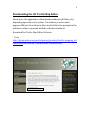
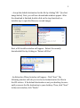
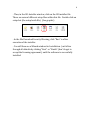
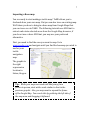
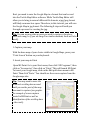
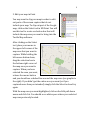
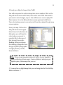
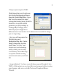
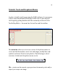
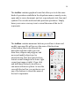
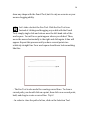
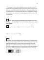
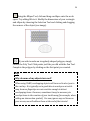
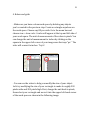
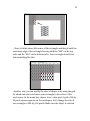
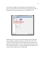
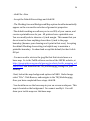
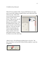
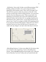
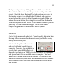
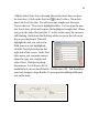
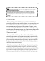
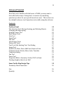
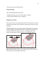
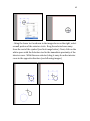
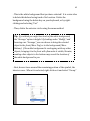
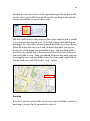
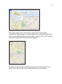
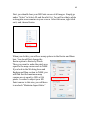
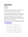
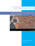
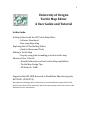
University of Oregon
Tactile Map Editor
A User Guide and Tutorial
In this Guide:
Getting Started with the UO Tactile Map Editor
- Software Download
- Base-map Importing
Exploring the UO Tactile Map Editor
- Guide to Menus and Tools
Making a Tactile Map
- Step-by-step guide to making your first tactile map
Advanced User Tutorial
- Detailed elaboration of tools and editing capabilities
- Tactile Map Design Tips
- MS Paint for TaME
Supported by NSF-HRD-Research in Disabilities Education (grants
#0533251, #0928074)
Any opinions, findings, and conclusions or recommendations expressed in this
material are those of the author(s) and do not necessarily reflect the views of the
National Science Foundation.
1
2
Copyright 2011 Spatial and Map Cognition Research Laboratory, Department of
Geography, University of Oregon
Acknowledgements:
Special thanks to Matt Millett, for his helpful contributions to early drafts of the
tutorial.
We thank Pol Jackson for his assistance, and material provided in early versions of
this User Guide and Tutorial. We would like to extend our thanks to Xiangkui Yao,
who was the primary programmer of TaME, and helped in tutorial testing. We also
thank the participants who assisted in early versions of the workshops as well as in
reviewing the materials.
Please note that this user manual contains instructions and screen captures
for TaME downloaded with default settings and run on a typical PC desktop or
laptop. If you run TaME under other conditions, the instructions and screens
may appear somewhat different.
3
Welcome to the UO Tactile Map Editor!
The following tutorials are designed to get you started on tactile map
production using the University of Oregon Tactile Map Editor. This
document comes in three sections. The first section, Getting Started
with the UO Tactile Map Editor, shows you how to download the
software and import a basemap. The second section, Working With the
Tactile Map Editor, shows you how to use several of the common tools
the program provides. The third section, Make Your First Tactile Map,
provides a short exercise to work through, to help you get more
comfortable with the software.
After you are familiar with the basics, begin exploring the tools in
greater depth. The final section, the Advanced Tutorial offers detailed
explanations of tool usage, and includes tutorials for more advanced
operations. Also, make use of the Help menu, which includes both
assistance with tasks and additional tips.
Contents
Downloading the UO Tactile Map Editor
Importing a Base-map
4
7
Tools and Dropdown Menus
12
Advanced Tutorial
39
Make Your First Tactile Map
Computer Braille Tips
25
72
Downloading the UO Tactile Map Editor
4
Please note: the appearance of downloads windows will likely vary
depending upon the user’s system. If a window you encounter
appears different from those in this tutorial, follow the prompts in the
window in order to proceed with the software download.
Download the Tactile Map Editor Software.
- Go to
http://geography.uoregon.edu/geocog/products/tactile_mapping_sof
tware.html and click on “Download the Software Here”.
5
- Accept the default destination for the file by clicking "OK." (See first
image below) Next, you will see a downloads window appear. After
the download is finished, double-click on the top download, uoinstaller.zip, to open the files (see second image).
Next, a UO-Installer window will appear. Extract the recently
downloaded files by clicking on “Extract all Files.”
- An Extraction Wizard window will appear. Click “Next.” The
following window will ask you to select a destination for the files in
the ZIP archive. If the default destination is not your desktop, browse
until you move the file destination to your desktop. Then, click “Next.”
In the next window, click “Finish.”
6
- Then, in the UO-Installer window, click on the UO installer file.
There are several different setup files within this file. Double-click on
setup.bat (the setup batch file). (See graphic)
- In the File Download Security Warning, click “Run” to allow
execution of the installer.
- You will then see a Wizard window for Installation. Just follow
through all defaults by clicking “Next” or “Finish” (don’t forget to
accept the licensing agreement), until the software is successfully
installed.
Importing a Base-map
7
You are ready to start making a tactile map! TaME allows you to
freehand draw your own map. But you can also trace an existing map.
We’ll show you how to bring in a base-map from Google Maps that
you can trace over in TaME. The following tutorial uses MS Paint to
extract and rotate selected areas from the Google Map; however, if
you do not use or have MS Paint, you may use your preferred
alternative.
First, you need to find the area you want to map. Go to
www.google.com and navigate until you find the basemap you wish to
use for your
tactile
navigation
map.
The graphic to
the right
represents a
location in
Salem, Oregon.
Tip: While your map user needs will likely vary from
person to person, start with a scale similar to that in the
previous graphic. Also, you may want to expand the frame
of the Google Map. You can do this by grabbing the left side of
the map area and dragging it leftward.
8
Next, you need to save the Google Map in a format that can be read
into the Tactile Map Editor software. While Tactile Map Editor will
allow you to bring in several different file formats, a jpg/jpeg format
will likely consume less space. Therefore, in this tutorial, you will save
the Google Map in jpg format. The following 8 steps will walk you
through a process for creating the jpg.
Tip: You can use any other process you wish to capture a Google or
other web map (i.e. if you use Snag-It or similar methods, those will also
work).
1. Capture your map
With the base-map of your choice visible in Google Maps, press your
“Print Screen” button on your keyboard.
2. Insert your map in Paint
Open MS Paint. Go to your Start menu, then click “All Programs”, then
click on “Accessories”, then click on “Paint.” This will launch MS Paint.
To insert your Google map, click on the Edit pull-down menu in MS
Paint. Then click “Paste.” You should see the screen capture from the
Google maps site.
Tip: You may need to move the
window’s scrolling bars around
until you see the part of the map
you want to capture (see graphic
for example of screen capture
pasted in MSPaint as well as
identification of the scrolling bars
– the ovals).
9
3. Edit your map in Paint
You may want to clip your map in order to edit
out parts of the screen capture that do not
include your map. To clip-out part of the Google
map, click on the Select tool in MS Paint. You will
use this tool to create a selection box that will
include the map area you want to bring into the
Tactile Map software.
After clicking on the Select
tool, place your mouse in
the upper-left corner of the
map area that you want to
capture. While holding the
left-mouse button down,
drag the selection box to
the bottom-right corner of
the map area you want to
capture. When you have
selected the area you want,
release the mouse button
and you should see a dashed line around the map area (see graphic to
the right). If you didn’t get the entire area you want (or if you
captured more than you intended) simply click the Select tool and try
again.
With the map area you want highlighted, click on the Edit pull-down
menu and click Cut. You should see a white space where your selected
map was previously located.
10
4. Ready your Map for Import Into TaME
You will now paste the selected map into a new window. Click on the
File pull-down menu in MS Paint, then select new. If MS Paint asks if
you want to save changes, say no. You will then see a new empty MS
Paint canvas. Go to the Edit pull-down menu again and click Paste.
Your selected map area is now extracted from the original Google map
screen capture.
Save your map. Click on the
File pull-down menu again.
Select Save As. In the Save As
dialog box, you will need to
select where you want to
save the file. In the case of
this tutorial, choose the
Desktop. After you choose
the desktop, change the Save
As type to JPEG (see graphic
on right). Name your file,
then click Save.
Tip: On your own computer system, it will be to your benefit to
build a collection of base maps. Create a folder in which you put
digital copies of base maps that you use.
!! You now have a digital map that you can bring into the Tactile Map
Editor software. !!
11
5. Import your map into TaME
Finish importing your Google map
into the tactile mapping software.
Open the Tactile Map Editor. If you
don’t see the canvas (the white
rectangular drawing area), click File
then New. Accept the default
geometric property settings by
clicking OK (see image). Note:
different projects might need
different sizes. You can also set the dimensions to match the image
you are importing.
- Next, you will encounter the
Working Area and
Background Map Box. Under
Image, change the selection
from “None,” to “File,” and
then browse on the desktop
until you find your recently
created map. Select that map,
accept the default working
area size and canvas, and click
OK.
- Congratulations! You have created a base-map and brought it into
TaME. At this point, you can close this new document without saving
your changes, and move on to the Tools and Dropdown Menus
Tutorial.
Tutorial: Tools and Dropdown Menus
12
In order to build a tactile map using the TaME software, it is necessary
to have some foundational knowledge of the tools at your disposal.
Let’s begin by getting familiar with the commonly used tools of the
Tactile Map Editor – the menu bar, the tool bar and the toolbox.
The menu bar allows you to access a series of dropdown menus to
create and edit documents, insert text and images, modify lines and
symbols, and turn off and on tool palettes. The following is a brief
overview of what each dropdown menu can do:
File – create new documents, open previous documents, print and/or
export your map as an image
13
Edit – cut, copy, and paste text, lines and symbols; undo and redo
previous operations
View – zoom in and zoom out, change the size of the work-space,
show and snap to grid, show ruler, and turn on and off items in the
tool bar. The “Working Area in Canvas” option is helpful in designing
your tactile map to fit a printable page.
Insert – insert an image
Modify – transform, arrange, group and ungroup, combine and break
apart, and perform other operations on lines, symbols and text in the
work space
Tools – use options to set the size of gridlines, set the default
document size and manage fonts; this is where you can also import a
background map.
Window – can make visible or invisible the Toolbox, Text Styles
Menu, and Symbol Library
Help – offers an in-depth index of topics concerning the Tactile Map
Editor
14
The tool bar contains graphical icons that allow you to do the same
kinds of operations available in the dropdown menus, namely create,
open and/or save a document, and cut, copy and paste text, lines and
symbols. You can also undo and redo previous operations. Simply
hover your cursor over any icon to reveal the name of the tool it
represents.
The toolbox contains numerous buttons you will use to draw and
modify your map. We will go over the some of the functions
of the toolbox later in the tutorial, but
know that with the toolbox you can
draw lines, ellipses and polygons, and
move and modify objects you’ve
already drawn. Note that some buttons
feature a small triangle in the lower right
corner (see image at right). If you click
and hold these buttons, you will see a
sub-menu with more options. As was the
case with the tool bar, you can hover over
any of the buttons to reveal the name of
the tool it represents.
15
-The Text Style menu and Symbol Library will also be helpful in your
use of TAME. In the “Text Style” menu, you can
change the font, font size, font weight (the
thickness or boldness of the font), style (italic or
oblique), the variant (normal or small-caps), and
the amount of stretching that is applied to the
font. The “Symbol Library” contains both builtin and custom symbols (ex. You can use the
specified symbol for elevation change, or you
can customize symbols as needed.)
Now that you are familiar with the menu bar, toolbar, toolbox, text
style menu, and symbol library, we can get started.
1. Create a new document.
Choose file > new from the menu bar, or click the “new” button in the
tool bar to create a new document. Accept the default size setting by
clicking “OK,” and then accept the “None” option in the Working Area
and Background Map default box, and click “OK.”
2. Create some lines.
There are several kinds of line tools available and each of them
works a little bit differently. Begin by clicking on the Pencil
Tool. Click and drag a straight, horizontal line across the white space
(called the work space) in the middle of the page. The line will
probably appear a bit wavy. That’s because the Pencil Tool works just
like a real pencil. Wherever you drag it, a line will appear. You can
16
draw any shape with the Pencil Tool, but it’s only as accurate as your
mouse-dragging ability.
Let’s take a look at the Pen Tool. Click the Pen Tool icon.
Instead of clicking and dragging as you did with the Pencil
Tool, simply single click and release near the left-hand side of the
work-space. You will see a point appear where you clicked. Then,
move the mouse horizontally to the right and click again. A line will
appear. Repeat this process until you have several points in a
relatively straight line. Your work space should now look something
like this:
- The Pen Tool is also useful for creating curved lines. To draw a
curved path, you should click on a point, then click on a second point,
hold, and drag to create a curved line. Try it!
- In order to close the path of a line, click on the Selection Tool.
17
You can modify the newly created line using the Remove
Point Tool. This tool is very helpful for editing crooked or
inaccurate lines. First, however, you must make sure the line you
wish to modify is selected. Do this by either, choosing the Select Tool
and then clicking on the line, or by choosing the lasso tool and clicking
and drawing a circle around part of the line. Try both ways.
Once the line is selected, click on the Move Point icon and hold
your mouse button down. A sub-menu of three icons will be
revealed. Choose the Remove Point icon:
- The points you used to make the line should appear as blue squares.
Click on the points that make up the middle of your line (see image
below). As you do, you will see your line becoming straighter.
18
Tip:
Zooming In and Out
You can change your screen view in two distinct ways: 1) Click and
hold down the Zoom Tool
zoom out.
to reveal the options, zoom in or
2) In the bottom left corner of your working area, you can select
the percentage view of your choice.
Now let’s try using the Line/Street Tool. Click the Line/Street
icon, and then click and drag a horizontal line under the line you just
created with the Pen Tool. You’ll notice that the line can be made
perfectly straight by carefully placing the second point so that it is
“level” with the first. The Line Tool is your best choice to make
straight lines with beginning and end points.
Finally, let’s look at some special
line tools: the One-Way Street, Stair/Ramp, Water, Railroad, Sidewalk,
and Fence buttons. These require you to use the Pen or Pencil Tool,
creating the path you would like the special line tool to follow. After
you are satisfied with your line, select the line with the Selection Tool,
and click on the special line that you would like to be applied.
19
- You may get to a point where your work-space becomes cluttered
with practice lines. Simply use the Lasso Tool to draw a circle around
what you want deleted and hit the delete key. Alternatively, you can
also delete objects by clicking on the Selection Tool and then clicking
on the object. Once you see a rectangle appear around the object, hit
the delete key.
If you delete something accidentally and would like to retrieve
it, simply click on the “Undo” blue arrow in the tool bar, and the object
will reappear.
To redo an action, click on the forward-facing blue arrow.
3. Create some polygons and fills.
Now that you’re familiar with how lines work, let’s take a look
at creating some polygons. Make sure you have a clean work-space by
deleting any lines you’ve created in the previous step. Choose the
Rectangle Tool and click and drag a rectangle onto the workspace.
With the rectangle still selected, choose any one of the fills available in
the toolbox: Building, Parking Lot, Flexible, Water, Park, or Ground.
20
Using the Ellipse Tool, click and drag an ellipse onto the work
space. Try adding fills to it. Modify the dimensions of your rectangle
and ellipse by choosing the Selection Tool and clicking and dragging
the corners of the object (see image).
If you wish to make an irregularly shaped polygon, simply
choose the Poly Tool. Click points just like you did with the Pen Tool.
Complete the polygon by clicking on the first point you created.
Tip:
Why do some of my objects turn red?
When using TaME, overlapping objects will turn red to alert you to
the overlap. It is typically not a good idea to overlap on a tactile
map, because fingertips are not sensitive enough to detect
overlapping items. However, sometimes it may be necessary to
overlap items in the creation of your tactile map (for example, when
adding an intersection symbol). For now, ignore any red items on
your screen; we will address them at the end of the tutorial.
21
4. Rulers and grids
- Make sure you have a clean work space by deleting any objects
you’ve created in the previous step. Create a rectangle anywhere on
the work space. Choose any fill you wish. Go to the menu bar and
choose view > show ruler. A ruler will appear at the top and left side of
your work-space. The unit of measurement of the rulers is pixels. You
can change the unit of measurement to inches by clicking on the
square in the upper left corner of your image area that says “px.” The
ruler will convert to inches. Try it!
- You can use the rulers to help you modify the size of your object.
Let’s try modifying the size of your rectangle to make it roughly 300
pixels wide and 200 pixels high. First, change the unit back to pixels,
then select your rectangle and move it into the upper left-hand corner
of the work space as shown in the following image.
22
- Next, click the lower-left corner of the rectangle and drag it until the
outermost edge of the rectangle lines up with the “300” on the top
ruler and the “200” on the bottom ruler. Your rectangle should now
look something like this:
- Another way you can modify the sizes of shapes is by using the grid.
Go ahead and select and move your rectangle to the center of the
work-space. In the menu bar, choose view > show grid. A grid of 50-by50 pixel squares appears on the workspace. Let’s change the size of
our rectangle to 200-by-100 pixels. Make sure the object is selected
23
and move it so that the corner of it roughly matches the corner of one
of the grid cells.
Click and drag the corner of the rectangle until it is roughly 200 pixels
wide and 100 pixels high. Since the grid cells are 50-by-50 pixels, your
newly modified rectangle should be 4 grid cells wide and 2 high:
If you wish to change the size of the grid cells, simply click tools >
options in the menu bar. Use the “Grid Line Every (px)” dropdown in
the general tab to select the pixel size you would like. Try it!
24
Finally, choose view >snap to grid in the menu bar. Select and drag
your rectangle around the work-space. You will notice that it will
“snap” to the nearest grid line. This is handy if you want to place an
object in a particular place, or line up objects with each other. Turn it
off by simply choosing view > snap to grid again in the menu bar. You
are now ready to make your first tactile map!
Tutorial: Make Your First Tactile Map
25
This tutorial is designed to lead you through the production of a
tactile map using the UO Tactile Map Editor (TaME) software. These
steps will take you through the production of a single street map.
Along the way, tips will be offered and symbol use recommended.
However, all map users are individuals. Therefore, what may work
for one may not be as helpful for another. Ideally, the map-maker
either knows the map user or at least knows the needs of the map
user. Use this tutorial as a starting point. After you are comfortable
with the mapping process and user needs, customize symbols and
design to best suit your map user.
What you’ll need:
1.
2.
3.
4.
5.
UO Tactile Map Editor Software
Desktop or laptop computer
TM_Workshop.jpg file (found on SMCRL website)
Printing technology for microcapsule paper
Tactile image enhancer (or similar)
1. Begin with a Base-map
Base-maps are often a necessary tool in the creation of a tactile
map. The “Getting Started with the Tutorial,” section
demonstrates how to load a digital map (from Google, for
example) into TaME, using an image editing tool like MS Paint. For
the purposes of this tutorial, however, a base-map is already
provided.
26
- click File > New
- Accept the Default Size settings and click OK.
- The Working Area and Background Map option should automatically
appear on the screen after selection of geometric properties.
-The default working area allows you to use 80% of your canvas, and
creates a printable area for you. All printers have a printable area.
You are usually safe to observe a ½ inch margin. This means that you
do not want to draw anything closer than ½ inch to the page
boundary (because your drawing won’t print in that area). Accepting
the default Working Area setting is a helpful way to maintain a
printable boundary. Go ahead and accept this default, but don’t click
OK yet.
- You now need to retrieve the jpeg file that this tutorial uses as a
base-map. Go to the TaME software section of the SMCRL website, at
http://geography.uoregon.edu/geocog/products/tactile_mapping_sof
tware.html, and download the TM_Workshop.jpg, saving it to your
desktop.
-Next, look at the map background options in TaME. Under Image,
select “File.” Click Browse, and navigate to the TM_Workshop.jpg.
Once you have completed these steps, click OK.
-You should now see the base-map in your on-screen workspace. This
map is located on the background. You cannot modify it. You will
draw your tactile map over this base-map.
27
2. Build the Street Network
-Make all street symbols visible. If your symbol library is not open,
you can open it by clicking on Symbol Library on the right side of the
software screen. Click on the
arrow in the drop down menu
at the top of the Symbol
Library. When you do, you will
see a selection of symbol
libraries; choose Built-In. With
the Symbol Library open, you
may not be able to see all of the
map area. You can re-size the
Library by positioning your
cursor on the left side of the
Library window; click, hold
and drag the window, resizing
it until you can see the entire map.
-Add the streets. We will begin by adding a line to Scott Ave. The
Insert Line/Street tool from the Toolbox will be suitable to create this
straight line.
28
Position your cursor on the left end of Scott Ave (on the basemap).
Click, HOLD and drag your mouse cursor to the location where you
want the street to end. Once you release the mouse button, your
street will appear.
Remember: Save Often!
Tip: Tactile maps are often more legible when simplified.
Therefore, although Scott Ave has a bend in it on the map, create
a straight line in order to reduce unnecessary tactual “clutter.”
Your choice of tool will depend on the nature of the street, or line
that you want to create, since not all street lines are straight. If
your line is not straight, and you would like to represent the
variation in the line on your map, the Pen Tool in the Toolbox is
the most useful.
-Next add SE 25th Ct. (this is the street that runs vertically on the right
side of the lake). Again, select the Street tool. Begin at the bottom of
the map and stop before your line intersects with Scott Ave. You
should have a gap between Scott Ave and SE 25th Ct. We’ll fix that
now.
-You will use the Move Point tool to fix the gap. But first, let’s practice
with ZOOMING.
29
- Editing is sometimes easier when you zoom-in. In this step, you will
move the top point on the 25th Ct. line so that it intersects Scott Ave.
First, zoom in to the location you wish to
edit. Select the Zoom In Tool and
position your cursor over the location
where you will zoom (the gap between
the streets). Continue clicking until you
have zoomed to about the same level in
the graphic on the right. You may need
to move the window scrolling bars to
keep your zoom location centered in
your screen.
- You’re now ready to move the point. The Move/Add/Remove Point
tool is one of the most helpful editing tools you will use in tactile map
making. Click and hold down the left mouse button while positioned
over the tool. You will see the three options – Move, Add, and
Remove. For this step, make sure Move is
selected. In order to move a point on a
drawn object, that object must be selected.
If the 25th Ct. street line is not selected (i.e.
doesn’t have the blue dashed lines with
blue squares on the ends), use the
Selection Tool from the Toolbox to select
the line again. After the line is selected,
click the Move Point Tool again. You should now see the street line
with a single blue square on each end. If you don’t see that, go back to
the beginning of this step and try again.
30
-With the street selected and the Move Point Tool active, position the
mouse (you’ll see that the cursor is a cross) over the end point on 25th
Ct. that you will move to intersect Scott Ave. Click, HOLD, and drag
the point until it sits on the Scott
Ave. line. When you release the
mouse button, the line will be redrawn and the two lines
intersect.
-Return to full-screen zoom level by selecting Zoom – 100% from the
View pull-down menu.
-Make sure you have deselected the last line you created, and then
finish adding the remaining streets. Remember, if your streets don’t
intersect as you want them to, you can always zoom-in and move the
endpoints. Also, if you have multi-segmented streets (i.e. streets with
a jag in them that you want to include on the map) you may want to
use the Pen Tool from the toolbox. This tool allows you to create a
single line that contains multiple vertices (as opposed to the
line/street tool, which allows you to create lines with only beginning
and end points). You can practice using the Pen Tool here.
-Add the intersection symbols. The built-in Symbol Library contains
symbols for various types of intersections, including: without traffic
control (the open circle), with traffic control along one of the streets
(the circles with vertical and horizontal lines) and with traffic control
(traffic lights and signs) along both streets (the circle with vertical and
31
horizontal line). For this tutorial, you may choose symbols randomly
to use at the different intersections.
-To add intersection symbols to street intersections, click, HOLD, and
drag one of the intersection symbols from the Symbol Library to the
desired location on the map. When you release the mouse button, the
intersection symbol will be placed where you want it. However, if you
don’t like the location, you can simply select the symbol (using the
Selection Tool) and drag it to where you want it to be.
-You can also change the size of the intersection symbol. To do that,
select the intersection symbol and then click and hold down a corner
point on the symbol. With the corner point held down, move inward if
you would like to decrease the size of the object, or outward if you
would like it increased. Make sure to keep the shape of the symbol
consistent when resizing. Add intersection symbols to all of the
intersections on the map.
-If you have changed the size of your intersection symbol, you may
prefer to copy and paste the edited symbol, rather than resizing all of
your symbols. To copy your symbol, select it with the Selection Tool,
and within “Edit” in the Menu Bar, click on “Copy.” Then, deselect the
symbol, choose “Edit” in the Menu Bar again, and click on “Paste.” The
color of the symbol will change from black to red, because the newly
32
copied symbol is directly on top of the original symbol. Select the
symbol and move it, revealing the duplicated symbol.
Tip:
Want to keep your sizes consistent?
Hold down the shift key while you drag to re-size
3. Add Unique Features to Your Map
Add the railroad tracks. Select the Pen Tool in the
Toolbox. Position your cursor in the upper-left corner at the
beginning of the railroad. Click at various points along the path of the
railroad. Remove points as necessary to create a line that runs along
the railroad. When you are satisfied with your line, select it with the
Selection Tool and click on the Rail-Line Tool in the toolbox.
- Edit the railroad tracks. The following example reveals a rail line in
need of editing. If you drew your rail line perfectly, draw another rail
line in a different location on the page to practice this editing. Make
sure the railroad line is selected. Now click and hold the
Move/Add/Remove Point tool until Remove Points is highlighted.
You will see the Rail Line turn back into a Pen Line, with all of the
points revealed (see second graphic below). By removing the points
in the curve, the line will straighten and better resemble the correct
path of the rail line. To remove points, simply click on them (with the
33
Remove Point Tool activated). When the line is suitably straight, reclick the Selection Tool, and the line will reappear as a Rail Line.
34
- Add the lake. Notice in the Toolbox several different polygon “fills” –
building, parking lot, flexible, water, park, and ground. Before
beginning to draw the lake, zoom in. Next, select the Polygon Tool.
You will click on points to define the perimeter of the lake. Add a
point at a location where the line changes direction. You can achieve
smoother lines by adding more points. When you get back to the
beginning of your perimeter line, click on the original/start point.
From the Toolbox, click the Water fill. Your polygon should now be
filled with the water symbol texture. If you polygon did not fill, you
may not have “closed” your polygon (clicked on the beginning point).
Or, you may have deselected the polygon. If that is the case, select it
using the Selection tool, then click the water fill. Remember, you
cannot make any changes to an object unless that object is selected.
-Add additional features. You have now added all of the features that
were included on the original map. Practice with adding other
features. Draw a stream through the bottom right corner of the map.
Use the Waterline Tool in the Toolbox; this tool works like the Rail
35
Tool you used previously. Add a park in one of the square blocks.
Remember to allow for some blank space between the park and the
streets. Select the Insert Rectangle Tool and position your cursor in
the interior corner of one of the blocks. Click, hold, and drag your
mouse to the other corner to define the entire rectangle. When you
release the mouse button, the rectangle is formed. Now click on the
Park texture symbol in the Toolbox. You now have installed a park on
your map. You can also use the Polygon Tool to create a more
complex polygon; then fill with the Park texture symbol.
4. Add Text
-Not all tactile maps need added text. You will need to determine how
the map will be used as well as the user’s needs (and Braille reading
ability) before adding text.
-The Tactile Map Editor allows you to
add any font that is loaded into your
computer. Therefore, the availability of
specific fonts, especially Braille, is not
dependent exclusively on TaME, but is also dependent on the number
and types of fonts that are available on your computer. The Swell
Braille font is already included in the software. If you want to add
additional Braille fonts, some freely downloadable fonts are available.
Instructions on how to use Braille font are included in at the end of
this tutorial.
36
-Add the label, Scott Ave to the map (above the street line you drew
for Scott Ave). Click on the Text tool
in the Toolbox. Then click
above the Scott Ave line. You will see some sample text that says
“here is the text.” That text is highlighted blue. You can type the new
text (Scott Ave), which will replace the highlighted sample text. When
you get to the end of the text (the “e” in Ave in this case), the cursor is
still blinking. Hold down the Shift key while you press the left arrow
key on your keyboard. This will
highlight the text you just wrote.
With your new text highlighted,
click the Text Style button on the
right side of the screen. In the Text
Style menu, you can make choices
about the type, size, weight, and
style of font. Click the top dropdown menu. You will see a list of
available font; choose Swell Braille. Set the size to 24. You should see
your text change to large Braille. You can practice adding additional
text on the map.
37
Tip:
When Saving Your Map- You can save different versions of the
same map using different file names. For example, if you are
working with two students and think they each need different
symbols/objects on their tactile maps, save a version for each
student.
6. Print your map
- Before printing, you should change any red items to black if you
would like them to have the option of puffing. You can remove the red
from individual items by first moving the item to a place where it is
not overlapping any other objects, then clicking on “Modify” in the
menu, de-selecting the “Check Constraint” option, and finally moving
the item back to its intended location. Or, if you would all items on the
page to be black, simply click on “Modify” in the menu, and select
“Convert Red to Black.”
- You can print the tactile map either with or without the base-map
present on the printout (you probably do not want to print the basemap as it will just cause clutter). To print without the base-map, go to
the File pull-down menu and select Page Setup. Then, in the Include
Background or Not window, click on Print without Background (you
can always change these settings).
- To finish your print, go to File, Print Image. Be patient, it may take a
moment for the printing options to appear. Then select your print
method (this will vary depending on the print system you have). Click
OK. Remove the map from the inkjet (be careful, as the ink smears).
Allow your map to dry (at least 10 minutes is ideal). Send your map
38
through the tactile image enhancer (again, you may use a different
method, depending on what tools you have at your disposal).
Congratulations!! You’ve made your first tactile map with TaME!!
Use this as well as the other provided tutorials to continue exploring
TaME features. The best way to learn software is to get in there and
use it!
Advanced Tutorial
39
Now that you’re familiar with the basics of TaME, you may want to
learn alternative ways of using tools, or answer any remaining
questions you have for your specific needs as a user. This section can
be a helpful reference tool if questions arise while using the software.
Contents:
Toolbox Panel
The Selection Tool: Moving, Resizing, and Deleting Objects
Grouping and Ungrouping
Using the Lasso Tool
Basic Shape Tools
Poly Tool
Pencil Tool
Pen Tool
Line Feature Tools
Pattern Fill Tools
Text Tool: Edit Existing Text, Text Styling
Image Tool
Point Tools: Move Point, Add Point, Remove Point
Transform Tools: Rotate, Skew, Scale, Translate
Transform Dialog
Pan Tool
Zoom Tool
Properties Editor: Geometry, Stroke, Fill, Text Style
Printing Graphics that do not Puff
41
41
43
43
44
44
45
45
46
46
47
47
48
49
51
51
52
52
54
Size
Quantity
56
56
Some Tactile Map Design Tips
Proximity: Check Constraint
55
55
40
Some Tactile Map Symbols
About
Symbol Library
Create Custom Symbols
Breaking Apart Symbols
57
57
58
58
61
MSPaint for TaME: Cropping, Rotating, Resizing
65
What is TaME?
Computer Braille Tips
71
72
Toolbox Panel
41
The Toolbox panel consists of various tools that you can use to create
and edit your map. It contains tools that allow you to select, draw, and
edit objects. It also includes common line features such as water,
sidewalk, one-way street, and railways. Additionally, it contains
pattern features such as water, park, ground and building. There are
many useful tools and operations in TaME. This section details the
ways that you can use the many tools in TaME.
The Selection Tool is used to select object(s) for manipulation.
There are two types of Selection Tools:
-The Normal Selection Tool is constrained by the grouping element. It
will select the entire group if the object(s) you select is contained
within a group.
- The Direct Selection Tool allows you to directly select object(s)
regardless of the grouping element.
Before you can modify an object, you need to select the object first.
You do that by selecting the object with the Selection Tool. Once
you've selected an object, or a part of an object, you can edit it by
moving, deleting, or resizing.
42
To select an object or objects:
-Click the Selection Tool.
-In the canvas, drag the mouse to enclose the object(s).
If the object is successfully selected, the object will show the selection
border and the properties window will show the properties of that
object.
Note: To add selections, hold down Shift while selecting additional
objects.
Moving Objects
You can move a selected object by dragging it. To move an object or
objects:
-Use the Selection tool to select an object or objects.
- Move the mouse inside the selection border.
-Press, hold, and drag the mouse into the new location.
Resizing Objects
You can resize the object by dragging the selection border into the
desired size. To resize an object or objects:
- Use the Selection tools to select an object or objects.
- Move the mouse inside the selection border's border.
- Press, hold, and drag the mouse into desired size.
Deleting Objects
To delete an object or objects:
-Use the Selection tools to select an object or objects.
43
- On the canvas, press the delete key.
Group/Ungroup
You can group/ungroup object(s) by:
- Using the Selection tool to select an object or objects.
- Going to Menu Modify: Group or Ungroup
Using the Lasso Tool
The Lasso Tool is a convenient alternative to the Selection Tool, and is
especially useful when your document contains many objects in close
proximity.
- When using the Lasso, it is not necessary to draw the Lasso around
the entire object you would like to select. Simply draw a small circle
around an EDGE of the object that is not overlapping with other
objects, and that object will be selected. (see following images)
Note: Simply drawing a lasso circle inside an object will not select it,
the Lasso must cross an edge of the object.
Basic Shape Tools
Rectangle, Ellipse, and Line are the basic shapes from which you can
choose. You can draw basic shapes by dragging with one of these
tools.
To draw a basic shape:
- Click the Rectangle, Ellipse, or Line tool.
- Press, hold, and drag the mouse into the desired size.
Poly Tool
Tactile Map Editor provides a special tool to draw poly objects
(polyline or polygon). To draw a poly object:
- Click the Poly tool.
- Press, hold, and drag the mouse into the desired size and location.
- To create a closed shape, click the initial point.
44
Pencil Tool (Freeform tool)
The Pencil tool is used to draw a freeform path that follows the
direction of mouse movement. To draw a freeform path:
- Click the Pencil tool.
- Press, hold, and drag the mouse into the desired size and location.
Pen Tool
The Pen tool lets you draw a curved path. To draw a curved path:
- Click the Pen tool.
- On the canvas, click the location of the desired point.
- Press, hold, and drag the mouse into the desired size and location,
where dragging forms the curve.
- To close the path, click on the Selection tool.
Note: To draw a straight line, just click the location of the desired
starting point and end point, and then click on the Selection tool to
close the path.
45
Line Feature Tools
46
Line feature tools are used to create different line styles on the map;
they follow the direction of mouse movement. The line features
included in this tool are One-way Street, Stairs or Ramps in Sidewalk,
Water Line, Railway, Sidewalk, and Fence.
-Draw and select a path or line on the canvas. Then click on the line
feature you want.
-The path/line you select will be automatically converted to the
corresponding line feature.
Pattern Fill Tools
Pattern fill tools are used to show area features on the map. The
pattern fill features included in this tool are Building, Parking Lot,
Flexible, Water, Park, and Ground. This is how you use pattern fill
tools:
-Draw an object with area on the canvas, using tools like Rectangle,
Ellipse, or Poly-line tools.
-Select the object.
-Click on the pattern fill feature you would like to apply to the area.
-The interior of the object will be automatically filled with that pattern
(area) feature.
Text Tool
47
The Text Tool allows you to add text to the canvas. To use the Text
Tool:
- Click the Text icon.
- On the canvas, click the location of the desired text.
- Leaving, “here is the text” highlighted, type your desired text.
Edit Existing Text
- Click the Text icon.
- On the canvas, highlight the location of the existing text.
- Using keypad arrows, move the cursor left or right to position the
Text cursor in the desired location.
- Type the text.
Text Styling
- Highlight the Text using shift left or right.
- In the Text Style Editor, choose the desired font characteristics.
Image Tool
Image tool lets you add an Image (Raster or SVG) into the canvas. To
use the Image tool:
- Click the Image icon.
- Press, hold, and drag the mouse into the desired size.
- Insert Image Window will open.
48
- Browse until the desired image is selected, and click OK.
- If you are using this method, some properties are automatically filled
up for you (x,y,width,height). However, you can override these values
by typing new values.
Point Tools
You can reshape an object by adjusting a point's handles using Point
Tools. These Point Tools consist of: Move, Add, Delete, and Point.
Note: The manner in which the Point Tool works depends upon the
nature of the object. For example, Add/Delete Point will only work on
Poly-line, Polygon, and Path objects.
Move Point
To adjust the points of a selected object or objects:
- Use the Selection Tool to select an object or objects.
- Click the Move Point Tool.
- Drag the desired point to a new location.
- Please note that if the path is created by the Pen tool, it may be a
curve. In that case, it is very likely that you need to move reference
points for a particular curve. To do that, 1) Click on the point (solid
square) you select, and some points (unfilled squares) will appear; 2)
Move these points to adjust the curves.
Add Point
49
To add a point to a selected object or objects:
- Use the Selection tools to select an object or objects.
- Click the Add Point Tool.
- Click on the path of the shape to add a new point.
Remove Point
To remove a point from a selected object or objects:
- Use the Selection tools to select an object or objects.
- Click the Remove Point Tool.
- Click on the desired point to delete the point.
Transform Tools
The transform tools consist of: Rotate, Skew, Scale, and Translate.
These tools use the transform matrix to modify the objects.
You can also transform selected objects using Transform Dialog.
Rotate
You can rotate the selected objects using the Rotate tool. To rotate the
selected object:
- Use the Selection Tool to select an object or objects.
- Click the Rotate tool.
- Drag the mouse on the canvas in the direction that you would like
the object to turn.
50
Skew
You can skew/shear selected objects using the Skew tool. To skew the
selected object:
- Use the Selection Tool to select an object or objects.
- Click the Skew tool.
- Move the mouse into the border of selected objects on the mark
provided.
- Drag the mouse on the canvas.
Scale
You can scale, or enlarge, selected objects using the Scale tool. To scale
the selected object:
- Use the Selection Tool to select an object or objects.
- Click the Scale tool.
- Move the mouse into the border of selected objects on the mark
provided.
- Drag the mouse on the canvas.
- If you want to keep the shape of your object consistent (maintaining
a fixed ratio between width and height), press the SHIFT key while
dragging your mouse.
Translate
You can translate, or move and adjust, the selected objects using the
Translate tool. To translate the selected object:
- Use the selection tools to select an object or objects.
- Click the Translate tool.
- Move the mouse into the border of selected objects.
51
- Drag the mouse on the canvas.
Transform Dialog
Transform dialog enables you to make precise modifications to an
object, such as specifying the degree of rotation or the specific extent
you would like a shape to be skewed. In the transform dialog window,
you can change the transform attribute of selected objects. Simply
type the desired value into the text field provided, click the apply
button, and the changes will be reflected automatically on the canvas.
In order to access this window:
- Choose Menu > Modify > Transform > Transform Dialog.
Pan Tool
You can pan the canvas (move around the area of your canvas that is
displayed) using Pan tool. To pan the canvas:
- Click the Pan tool
- Press, hold, and drag the mouse on the canvas.
52
Zoom Tools
You can zoom in or out to magnify or reduce your view using the
Zoom Tool. To zoom your view in or out:
- Click the Zoom Tool (zoom in or zoom out).
- Click the mouse on the canvas.
Properties Editor
The properties of most objects that are represented in the canvas can
be viewed in a properties panel. In this panel, the properties of
selected objects are shown. The properties window is divided into 4
categories: geometry, stroke, fill, and filter. In each of the categories
you can change the value shown in the canvas.
This section contains the following:
Geometry Properties
In the geometry properties, you can change the geometric value of
selected objects. For instance, you could adjust the size of an object to
a set pixel value. Simply type the desired value into the text field
provided, press enter, and the changes will be reflected automatically
on the canvas.
Stroke Properties
53
Stroke properties enables you to edit various stroke (line) values of
selected objects, such as color, width, line cap, line join, miter limit,
opacity, etc. To use the stroke properties, type the desired value into
the text field provided and press enter; or use the combo box to set
the predefined value, and the changes will be reflected automatically
on the canvas.
Fill Properties
Fill properties lets you edit various fill values of selected objects, such
as color, rule, and opacity. To use the fill properties, type the desired
value into the text field provided and press enter; or use the combo
box to set the predefined value, and the changes will be reflected
automatically on the canvas.
Using Text Style Editor
Text Style Editor lets you edit various text styles of the selected text
object, such as font, font size, font weight, underline/overline, etc.
Before you change the text property, you must select and highlight the
text that you would like to modify:
- Use the Text tool to select the particular text.
- Highlight the Text using shift left or right.
- On the Text Style Editor, choose the desired value eg: font-size, fontweight, etc.
- Please note that the tool installs Swell Braille font. If you need to use
other Braille fonts, you need to install them under windows, and then
go to the Option menu and choose the Braille fonts you install.
Note: To change the available font, choose Edit Font List on the Font
ComboBox.
Printing Graphics that do not Puff
54
- In order to create graphics or text that will not puff, it is necessary to
decrease the saturation of the
black color in the object. This can
be accomplished within the
Properties Editor. First, you must
Select the object that you do not
want to puff, and then within the
Fill section of the Properties
Editor, click on Color.
Selecting a dark gray instead of
black will likely be sufficiently unsaturated to not puff; however, if
you would like to be more precise,
you can click on the RGB tab to
manually decrease the saturation.
You can do this by increasing the
amount of red, green, and blue, as
shown in the image to the right.
Some Tactile Map Design Tips
55
Before you start using the tool, you may want to know some tips
about designing tactile maps.
We have adopted many of the tactile graphic design guidelines
proposed by the Braille Authority of North America (BANA). The three
primary guidelines include: proximity, size, and quantity.
Proximity:
The software includes a proximity warning feature. If a map object is
placed too closely to another object (within .7cm), then the object that
is being placed turns red. Once that object is a sufficient distance from
other objects, it returns to the original color. The map designer has
the option to follow the guidelines and move the object or to print the
object that is violating the proximity guideline (i.e. red objects will
print).
Check Constraint
For tactile maps to
be "readable" by
fingertips, objects on
maps should not be
too close to each
other. The “Check
Constraint” tool has
a built-in
functionality to
check this important
component of tactile
maps.
56
You can turn the function on/off by go to "Modify" menu and click on
the "Check Constraint" toggle button shown above. Also, the “Convert
Red to Black” option is useful, because it will remove the red from all
objects in your document.
The Check Constraint tool works by:
- Whenever a new object is drawn or moved onto the canvas, this tool
checks whether that particular object is too close to other existing
objects on canvas. If it is, the stroke of this object will be painted red.
- Once this object is moved far enough away from other objects, its
stroke will be painted black again.
- Note: If you need to change the colors of elements on the canvas (for
example, when decreasing the saturation of black to make printable
objects that do not puff), you need to uncheck the check constraint
button.
Size:
All of the embedded symbols are drawn at a size of at least .7cm. The
map design has the option to resize (and reshape if desired) all of the
symbols. But, we recommend that designers adhere to the BANA
guideline of size – that all objects should be at least .7cm.
Quantity:
A third guideline concerns the number of map objects placed on the
map. A general guideline suggests that a maximum of three point, line,
and polygon symbols are included. This guideline is more flexible, as
some map users can remember and distinguish more and some less.
Some Tactile Map Symbols
57
About our map symbols:
We have developed a set of symbols, which are divided into three
categories: point symbols, line symbols, and area/polygon symbols.
These symbols were developed through three years of research,
which included surveys from professionals in the field, consultation
from researchers and professionals in the field, and field testing.
Realizing that not all environmental features can be represented with
distinct and discriminable symbols, our objective was to identify the
most important environmental features and assign symbols that have
been shown to be discriminable. We adopted a Flexible Symbology
approach. This approach allows us to use modifier symbols that we
can add to the existing symbol set, providing either new or altered
meaning to the existing symbols. For example, we use a Triangle
symbol to indicate direction. Placed in a road, the triangle indicates a
one-way street (with traffic flowing in the direction of the triangle
tip). Placed on a sidewalk, the triangle indicates a distinct dip or rise,
or, placed with the passage symbols, the triangle indicates either a
bridge or a tunnel. These are examples, however the triangle can be
used with any symbol to indicate some form of direction. Also, we
have used the small Square (point symbols) to represent a Challenging
feature. This is a feature that can change from map to map. For
example, if construction is present, the Challenging symbol would be
placed on the map and the map user would know to check the key for
an explanation of the Challenging feature. Like the Triangle, this
symbol is flexible (though meaning is restricted to something that is
challenging). Finally, we have adopted the filled Circle (point feature)
and Circle pattern (area/polygon feature) to be a completely flexible.
When these symbols are used on the map, again, the map user is
prompted to check the key for an explanation of the special object the
Circle is representing.
58
All of the symbols are embedded in the software, either as drag-anddrop point symbols or as patterns that can be applied to line or
area/polygons.
A complete symbol set is available in PDF form in the help section of
the software.
Symbol Library
The Symbol Library provides various symbols for Drag and Drop
operation onto the canvas. There are more than a dozen "built-in"
symbols for making tactile maps that are included with TaME. Also,
users may define their own "custom" symbols and save them into the
symbol library. To open the symbol library, go to the "Window" menu
and select "Symbol Library".
To Drag and Drop a symbol onto the Canvas:
- Click on the desired symbol.
- Drag the symbol onto its preferred location on the canvas and
release.
Create Custom Symbols
While the symbols that are built into the software will satisfy the
needs of most users, you may want to create your own customized
symbol to refer to a particular type of object or intersection.
59
- In order to create and save your custom symbol, you should first
design it using shape tools such as rectangle, ellipse, or polygon, or by
using the pen or pencil tool. Note: The software will not allow you to
create a symbol using the special line tools such as railway line tool or
water line tool.
- The “Arrange” options may be helpful when designing your symbol.
These can be found under “Modify” in the menu bar. When you hover
over “Arrange,” you will see the following options: Move Top, Move
Up, Move Down, and Move Bottom. These options will enable you to
rearrange or layer the objects composing your symbol in whichever
order you prefer.
- The “Transform” options, also found under “Modify” in the menu
bar, consist of “Flip Horizontal,” “Flip Vertical,” and “Transform
Dialog.” These first two options enable you to reflect your images
vertically or horizontally. The third option, “Transform Dialogue,”
enables you to make more precise modifications to your objects, such
as specifying the degree of rotation or specific extent you would like a
shape to be skewed.
60
- If overlaps within your symbol are creating red lines or objects, you
should select your entire symbol. Then, under “Modify,” click on
“Convert Red to Black.”
- Next, right click on your symbol again and select the “Create Symbol”
option. You will be asked to choose a name for this new symbol. Do
so, and then press, “OK.” When you open the Symbol Library, you
should see your new custom symbol within it.
- If you would like to delete a custom symbol, simply highlight the
symbol within the symbol library by clicking on it and then press the
delete key on your keyboard.
Breaking Apart Symbols
61
While using the software, you may want to modify a built-in symbol to
suit your needs. To do this, it is not necessary to create a new
customized symbol; you can simply break apart the existing built-in
symbol.
- To break apart a built-in symbol, begin by dragging it from the
symbol library onto your canvas. For this exercise, let’s use the 4-way
control symbol found in the Built-In Symbol Library.
- After dragging the symbol onto your canvas, select it, right click on it,
and select “Ungroup.” Generally, when you ungroup a symbol it will
separate into a background (which is white, and often difficult to
find!), an interior of the object, and its exterior. For this exercise, let’s
assume you would like to modify the 4-way control symbol so that it
only contains the interior cross, and does not have the circle around it
or the white background.
62
- Using the Lasso tool as shown in the image above on the right, select
a small portion of the exterior circle. Drag the selected area away
from the rest of the symbol (see first image below.) Next, click on the
white space with the Selection tool in the immediate proximity of the
interior cross. With this area selected, drag it away from the interior
cross in the opposite direction (see following images.)
63
- This is the white background that you have selected! It is a wise idea
to delete this before losing track of its location. Delete the
background using the delete key on your keyboard, or by rightclicking and selecting “Cut.”
- Then, delete the exterior circle using the same method.
Tip: If you think you might lose track of the white background,
the “Arrange” option is helpful. By looking under “Modify,” and
hovering over “Arrange,” you can choose to bring the selected
object to the front (Move Top) or to the background (Move
Bottom). If the white background is overlapping with any other
objects, bringing it to the front will often make it visible; likewise,
sending other objects to the bottom may reveal the location of
the white background to you.
- Next, draw a lasso around the remaining portion of the symbol, the
interior cross. When it is selected, right-click on it and select “Group.”
64
- You have now broken apart a built-in symbol! If you think you will
use this modified symbol in the future, you can save it as a custom
symbol using the method described in the “Creating Custom Symbols”
section of the tutorial.
MS Paint for TaME
65
A paint program has been included in all versions of Windows
computers, and can be a useful tool for base-map importation when
using TaME. If you have not yet used MS Paint on your computer, it
should be located in the “Accessories” folder among the list of all your
computer’s programs.
The three base-map modifications contained in this tutorial are 1)
cropping, 2) rotating, and 3) resizing. To begin, you should bring in a
base-map from Google Maps or a similar website. For instructions on
how to do this, see the earlier section, “Getting Started with the UO
Tactile Map Editor.”
Cropping
It is often essential to crop a base-map prior to bringing it into TaME.
Frequently, screen captures from websites such as Google Maps will
contain many elements unrelated to the map. The following image
contains an example of such visual clutter.
66
In order to crop out sections of the captured image that are not useful,
use the Select tool in MS Paint, and then click and drag to the desired
area you would like to use as a base-map.
You may want to move the portion of the screen capture that is visible
to you prior to selecting an area. To do this, simply click and drag on
the image. Or, if you have already pressed the Select tool, then choose
Select All within the Select tool, and click and drag until you can see
the section of the image you would like to use. You may then need to
re-click on the dotted box of the Select tool in order to select the area
you would like to crop. Then, you should click and drag until you have
a rectangular area you would like to use for a base-map, right click on
this selected area, and click on the “crop” option.
Rotating
Now that you have selected the screen area you would like to use for a
base-map, you may find it necessary to rotate it.
67
The above image shows the various options for changing the
orientation of your image. For this tutorial, let’s say you would like to
rotate your image 90 degrees to the right. Simply click on that option,
and your image will be rotated to that degree.
Because we will use this rotated basemap in the next section, it is a
good idea at this point to save this basemap to your desktop.
Resizing
68
The default sizing options in TaME utilize 80% of your canvas area for
your base-map. At times, you may find that you would prefer to use
all of your canvas with your base-map, or would like to have a smaller
base-map, and a more open area on the canvas. You can adjust these
preferences within TaME, in the initial options presented in the
Working Area and Background Map box. This area enables you to
choose the percentage of the canvas that you would like the base-map
to occupy, and also allows you to adjust the specific pixel size of the
working area.
However, at times you may want to have a base-map that does not
occupy all of your working area. In this instance, MS Paint will be
helpful for resizing your image.
In this exercise, let’s assume that you would like to have a base-map
that is oriented vertically, and takes up half of your working area.
This might happen, for instance, if you would like a large amount of
text to accompany your map. Using the map that has been rotated 90
degrees in MS Paint, let’s adjust the sizing of your base-map.
69
First, you should clear your MS Paint screen of all images. Simply go
under “Select” to Select All, and then hit Cut. You will see that a white
rectangular area remains on your screen. Select this area, right click
on it, and choose Resize.
When you do this, you will see many options in the Resize and Skew
box. You should first change the
Resize option to Resize by Pixels.
Then, you want to make the pixel area
equal to the map canvas area in TaME.
If you look in the Working Area and
Background Map section in TaME, you
will find that the maximum map
canvas area is equal to 1056 x 816
pixels. In order to adjust your MS
Paint canvas to this size, you will have
to uncheck “Maintain Aspect Ratio.”
70
Then, type in the pixel size of the TaME canvas, and click OK.
Next, Copy and Paste your rotated basemap onto MS Paint. Then,
Select the map, and click on the Resize option. To prevent skewing,
you will want to leave the Maintain Aspect Ratio box checked when
resizing the basemap itself.
To have a basemap that takes up half of your canvas, you should
adjust your pixels accordingly. Fifty percent is of your working space
equals 528 x 652 pixels. In MS Paint, if you input the width, the height
will adjust automatically. The area of your basemap will likely differ
from exactly 50 percent, in order to retain its proportions. Click OK,
click and drag your map to your preferred location on the white
canvas area, and save the image.
When you open this basemap in TaME, it will retain the open area
within your working space, enabling you to input whatever text or
alternative items you may want included.
What is Tactile Map Editor?
71
Tactile Map Editor is a vector drawing application for making tactile
maps based on SVG. It features various tools for optimizing content
creation, giving designers unsurpassed support for creativity. It offers
both visual design tool and source editing tools. More importantly, it
has built-in map features and symbols for making tactile maps. Also, it
allows users to make their own symbol libraries.
What is SVG?
SVG (Scalable Vector Graphics) is an open standard language for
describing two-dimensional (2D) graphics in XML. It is a W3C
recommendation. SVG allows for three types of graphic objects: vector
graphic shapes (e.g., paths consisting of straight lines and curves),
images and text. Graphical objects can be styled, transformed and
composited into previously rendered objects. The feature set includes
nested transformations, clipping paths, alpha masks, filter effects and
template objects.
Where do I find the SVG specification?
The SVG specification is available at http://www.w3.org/TR/SVG/.
Computer Braille Tips
72
The fundamental unit of Braille is the Braille cell, composed of six dots,
two columns across and three rows down. Dots in the cell are
numbered from one to six, as shown in the above figure.
There are two grades of Braille, Grade 1: in which words are formed
from letters alphabetically, and Grade 2 (or contracted English Braille):
in which words are written using abbreviations and contractions.
Swell Braille font is included in the software, which can be used to
produce both Braille 1 and Braille 2 script. In Grade 2 Braille, a wholeword contraction is shorthand for a whole word; a whole-word symbol
can be either one cell or a sequence of cells.
Whole-word contractions need to be either memorized or looked up in
a Braille dictionary. You can see BANA recommendations and updates
at www.brailleauthority.org