1
ModelSim
®
Advanced Verification and Debugging
SE
Graphical Interface Reference
Version 6.0c
GR-2
Copyright© Mentor Graphics Corporation 2005
All rights reserved.
This document contains information that is proprietary to Mentor Graphics Corporation.
The original recipient of this document may duplicate this document in whole or in part for
internal business purposes only, provided that this entire notice appears in all copies. In
duplicating any part of this document, the recipient agrees to make every reasonable effort
to prevent the unauthorized use and distribution of the proprietary information.
This document is for information and instruction purposes. Mentor Graphics reserves the
right to make changes in specifications and other information contained in this publication
without prior notice, and the reader should, in all cases, consult Mentor Graphics to
determine whether any changes have been made.
The terms and conditions governing the sale and licensing of Mentor Graphics products are
set forth in written agreements between Mentor Graphics and its customers. No
representation or other affirmation of fact contained in this publication shall be deemed to
be a warranty or give rise to any liability of Mentor Graphics whatsoever.
MENTOR GRAPHICS MAKES NO WARRANTY OF ANY KIND WITH REGARD TO
THIS MATERIAL INCLUDING, BUT NOT LIMITED TO, THE IMPLIED
WARRANTIES OR MERCHANTABILITY AND FITNESS FOR A PARTICULAR
PURPOSE.
MENTOR GRAPHICS SHALL NOT BE LIABLE FOR ANY INCIDENTAL,
INDIRECT, SPECIAL, OR CONSEQUENTIAL DAMAGES WHATSOEVER
(INCLUDING BUT NOT LIMITED TO LOST PROFITS) ARISING OUT OF OR
RELATED TO THIS PUBLICATION OR THE INFORMATION CONTAINED IN IT,
EVEN IF MENTOR GRAPHICS CORPORATION HAS BEEN ADVISED OF THE
POSSIBILITY OF SUCH DAMAGES.
RESTRICTED RIGHTS LEGEND 03/97
U.S. Government Restricted Rights. The SOFTWARE and documentation have been
developed entirely at private expense and are commercial computer software provided with
restricted rights. Use, duplication or disclosure by the U.S. Government or a U.S.
Government subcontractor is subject to the restrictions set forth in the license agreement
provided with the software pursuant to DFARS 227.7202-3(a) or as set forth in
subparagraph (c)(1) and (2) of the Commercial Computer Software - Restricted Rights
clause at FAR 52.227-19, as applicable.
Contractor/manufacturer is:
Mentor Graphics Corporation
8005 S.W. Boeckman Road, Wilsonville, Oregon 97070-7777.
This is an unpublished work of Mentor Graphics Corporation.
Contacting ModelSim Support
Telephone: 503.685.0820
Toll-Free Telephone: 877-744-6699
Website: www.model.com
Support: www.model.com/support
Contact technical writer: www.mentor.com/supportnet/documentation/reply_form.cfm
TRADEMARKS: The trademarks, logos and servicemarks ("Marks") used herein are the property
of Mentor Graphics Corporation or other third parties. No one is permitted to use these Marks without
the prior written consent of Mentor Graphics or the respective third-party owner. The use herein of a
third-party Mark is not an attempt to indicate Mentor Graphics as a source of a product, but is
intended to indicate a product from, or associated with, a particular third party. A current list of
Mentor Graphics trademarks may be viewed at: www.mentor.com/terms_conditions/trademarks.cfm.
ModelSim SE GUI Reference
Technical support and updates
GR-3
Technical support and updates
Support
Model Technology online and email technical support options, maintenance renewal, and
links to international support contacts:
www.model.com/support/default.asp
Mentor Graphics support:
www.mentor.com/supportnet
Updates
Access to the most current version of ModelSim:
www.model.com/downloads/default.asp
Latest version email
Place your name on our list for email notification of news and updates:
www.model.com/products/informant.asp
ModelSim SE GUI Reference
GR-4
Where to find our documentation
ModelSim documentation is available from our website at www.model.com/support or in
the following formats and locations:
Document
Format
How to get it
ModelSim Installation &
Licensing Guide
paper
shipped with ModelSim
PDF
select Help > Documentation; also available from the Support
page of our web site: www.model.com
ModelSim Quick Guide
(command and feature
quick-reference)
paper
shipped with ModelSim
PDF
select Help > Documentation, also available from the Support
page of our web site: www.model.com
ModelSim Tutorial
PDF, HTML
select Help > Documentation; also available from the Support
page of our web site: www.model.com
ModelSim User’s Manual
PDF, HTML
select Help > Documentation
ModelSim Command
Reference
PDF, HTML
select Help > Documentation
ModelSim GUI Reference
PDF, HTML
select Help > Documentation
Foreign Language
Interface Reference
PDF, HTML
select Help > Documentation
Std_DevelopersKit User’s
Manual
PDF
www.model.com/support/documentation/BOOK/sdk_um.pdf
The Standard Developer’s Kit is for use with Mentor Graphics
QuickHDL.
Command Help
ASCII
type help [command name] at the prompt in the Transcript pane
Error message help
ASCII
type verror <msgNum> at the Transcript or shell prompt
Tcl Man Pages (Tcl
manual)
HTML
select Help > Tcl Man Pages, or find contents.htm in
\modeltech\docs\tcl_help_html
Technotes
HTML
select Technotes dropdown on www.model.com/support
ModelSim SE GUI Reference
GR-5
ModelSim SE GUI Reference
GR-5
Table of Contents
Technical support and updates . . . . . . . . . . . . . . . . . . . . . . . . . . .GR-3
Where to find our documentation . . . . . . . . . . . . . . . . . . . . . . . . . .GR-4
. . . . . . . . . . . . . . . . . . . . . . . . . . . . . . . . . . . . . . .GR-5
1 - Simulator windows (GR-12)
Introduction . . . . . . . . . . . . . . . . . . . . . . . . . . . . . . . . . GR-14
Design object icons and their meaning . . . . . . . . . . . . . . . . . . . . . GR-15
Setting fonts . . . . . . . . . . . . . . . . . . . . . . . . . . . . . . . GR-16
Main window . . . . . . . . . . . . .
Workspace . . . . . . . . . . . .
Transcript . . . . . . . . . . . .
Multiple document interface (MDI) frame
Main window status bar . . . . . . .
Main window menu bar . . . . . . .
File menu . . . . . . . . . . .
Edit menu . . . . . . . . . .
View menu . . . . . . . . . .
Format menu . . . . . . . . .
Compile menu . . . . . . . . .
Simulate menu . . . . . . . . .
Add menu . . . . . . . . . .
Tools menu . . . . . . . . . .
Waveform Compare sub-menu . .
Code Coverage sub-menu . . . .
Functional Coverage sub-menu . .
Profile sub-menu . . . . . . . .
C Debug sub-menu . . . . . . .
Window menu . . . . . . . . .
Help menu . . . . . . . . . .
Main window toolbar . . . . . . . .
Main window dialogs . . . . . . . .
Create Project dialog . . . . . .
Create a New Library dialog . . .
Open File dialog . . . . . . . .
Import Library Wizard dialog . . .
Evcd Import dialog . . . . . . .
Save As dialog . . . . . . . . .
Create Project File dialog . . . .
Add file to Project dialog . . . .
Optimization Configuration dialog .
Simulation Configuration dialog . .
Add Folder dialog . . . . . . .
Find in Transcript dialog . . . . .
Dataset Browser dialog . . . . .
Project Compiler Settings . . . .
Project Settings dialog . . . . . .
Compile Source Files dialog . . .
.
.
.
.
.
.
.
.
.
.
.
.
.
.
.
.
.
.
.
.
.
.
.
.
.
.
.
.
.
.
.
.
.
.
.
.
.
.
.
.
.
.
.
.
.
.
.
.
.
.
.
.
.
.
.
.
.
.
.
.
.
.
.
.
.
.
.
.
.
.
.
.
.
.
.
.
.
.
.
.
.
.
.
.
.
.
.
.
.
.
.
.
.
.
.
.
.
.
.
.
.
.
.
.
.
.
.
.
.
.
.
.
.
.
.
.
.
.
.
.
.
.
.
.
.
.
.
.
.
.
.
.
.
.
.
.
.
.
.
.
.
.
.
.
.
.
.
.
.
.
.
.
.
.
.
.
.
.
.
.
.
.
.
.
.
.
.
.
.
.
.
.
.
.
.
.
.
.
.
.
.
.
.
.
.
.
.
.
.
.
.
.
.
.
.
.
.
.
.
.
.
.
.
.
.
.
.
.
.
.
.
.
.
.
.
.
.
.
.
.
.
.
.
.
.
.
.
.
.
.
.
.
.
.
.
.
.
.
.
.
.
.
.
.
.
.
.
.
.
.
.
.
.
.
.
.
.
.
.
.
.
.
.
.
.
.
.
.
.
.
.
.
.
.
.
.
.
.
.
.
.
.
.
.
.
.
.
.
.
.
.
.
.
.
.
.
.
.
.
.
.
.
.
.
.
.
.
.
.
.
.
.
.
.
.
.
.
.
.
.
.
.
.
.
.
.
.
.
.
.
.
.
.
.
.
.
.
.
.
.
.
.
.
.
.
.
.
.
.
.
.
.
.
.
.
.
.
.
.
.
.
.
.
.
.
.
.
.
.
.
.
.
.
.
.
.
.
.
.
.
.
.
.
.
.
.
.
.
.
.
.
.
.
.
.
.
.
.
.
.
.
.
.
.
.
.
.
.
.
.
.
.
.
.
.
.
.
.
.
.
.
.
.
.
.
.
.
.
.
.
.
.
.
.
.
.
.
.
.
.
.
.
.
.
.
.
.
.
.
.
.
.
.
.
.
.
.
.
.
.
.
.
.
.
.
.
.
.
.
.
.
.
.
.
.
.
.
.
.
.
.
.
.
.
.
.
.
.
.
.
.
.
.
.
.
.
.
.
.
.
.
.
.
.
.
.
.
.
.
.
.
.
.
.
.
.
.
.
.
.
.
.
.
.
.
.
.
.
.
.
.
.
.
.
.
.
.
.
.
.
.
.
.
.
.
.
.
.
.
.
.
.
.
.
.
.
.
.
.
.
.
.
.
.
.
.
.
.
.
.
.
.
.
.
.
.
.
.
.
.
.
.
.
.
.
.
.
.
.
.
.
.
.
.
.
.
.
.
.
.
.
.
.
.
.
.
.
.
.
.
.
.
.
.
.
.
.
.
.
.
.
.
.
.
.
.
.
.
.
.
.
.
.
.
.
.
.
.
.
.
.
.
.
.
.
.
.
.
.
.
.
.
.
.
.
.
.
.
.
.
.
.
.
.
.
.
.
.
.
.
.
.
.
.
.
.
.
.
.
.
.
.
.
.
.
.
.
.
.
.
.
.
.
.
.
.
.
.
.
.
.
.
.
.
.
.
.
.
.
.
.
.
.
.
.
.
.
.
.
.
.
.
.
.
.
.
.
.
.
.
.
.
.
.
.
.
.
.
.
.
.
.
.
.
.
.
.
.
.
.
.
.
.
.
.
.
.
.
.
.
.
.
.
.
.
.
.
.
.
.
.
.
.
.
.
.
.
.
.
.
GR-17
GR-18
GR-19
GR-20
GR-23
GR-24
GR-24
GR-26
GR-27
GR-28
GR-29
GR-30
GR-30
GR-31
GR-33
GR-34
GR-34
GR-35
GR-35
GR-36
GR-37
GR-38
GR-42
GR-42
GR-43
GR-44
GR-45
GR-46
GR-47
GR-48
GR-49
GR-50
GR-51
GR-52
GR-53
GR-54
GR-55
GR-62
GR-64
ModelSim SE GUI Reference
GR-6
Table of Contents
Compiler Options dialog . . . .
SystemC Link dialog . . . . .
Compile Order dialog . . . . .
Design Optimization dialog . .
Start Simulation dialog . . . .
Runtime Options dialog . . . .
Restart dialog . . . . . . . .
Waveform Compare dialogs . . . .
Load Coverage Data dialog . . .
Coverage Report dialog . . . .
Filter instance list dialog . . . .
Profile Report dialog . . . . .
Modify Breakpoints dialog . . .
Signal Breakpoint dialog . . . .
File Breakpoint dialog . . . . .
C Debug setup dialog . . . . .
Command entry dialog . . . .
Tcl debugger . . . . . . . .
Macro dialog . . . . . . . .
Drag and Drop Preferences dialog
Preferences dialog . . . . . .
Customize Toolbar dialog . . .
.
.
.
.
.
.
.
.
.
.
.
.
.
.
.
.
.
.
.
.
.
.
.
.
.
.
.
.
.
.
.
.
.
.
.
.
.
.
.
.
.
.
.
.
.
.
.
.
.
.
.
.
.
.
.
.
.
.
.
.
.
.
.
.
.
.
.
.
.
.
.
.
.
.
.
.
.
.
.
.
.
.
.
.
.
.
.
.
.
.
.
.
.
.
.
.
.
.
.
.
.
.
.
.
.
.
.
.
.
.
.
.
.
.
.
.
.
.
.
.
.
.
.
.
.
.
.
.
.
.
.
.
.
.
.
.
.
.
.
.
.
.
.
.
.
.
.
.
.
.
.
.
.
.
.
.
.
.
.
.
.
.
.
.
.
.
.
.
.
.
.
.
.
.
.
.
.
.
.
.
.
.
.
.
.
.
.
.
.
.
.
.
.
.
.
.
.
.
.
.
.
.
.
.
.
.
.
.
.
.
.
.
.
.
.
.
.
.
.
.
.
.
.
.
.
.
.
.
.
.
.
.
.
.
.
.
.
.
.
.
.
.
.
.
.
.
.
.
.
.
.
.
.
.
.
.
.
.
.
.
.
.
.
.
.
.
.
.
.
.
.
.
.
.
.
.
.
.
.
.
.
.
.
.
.
.
.
.
.
.
.
.
.
.
.
.
.
.
.
.
.
.
.
.
.
.
.
.
.
.
.
.
.
.
.
.
.
.
.
.
.
.
.
.
.
.
.
.
.
.
.
.
.
.
.
.
.
.
.
.
.
.
.
.
.
.
.
.
.
.
.
.
.
.
.
.
.
.
.
.
.
.
.
.
.
.
.
.
.
.
.
.
.
.
.
.
.
.
.
.
.
.
.
.
.
.
.
.
.
.
.
.
.
.
.
.
.
.
.
.
.
.
.
.
.
.
.
.
.
.
.
.
.
.
.
.
.
.
.
.
.
.
.
.
.
.
.
.
.
.
.
.
.
.
.
.
.
.
.
.
. GR-65
. GR-73
. GR-74
. GR-75
. GR-81
. GR-90
. GR-93
. GR-93
. GR-94
. GR-95
. GR-98
. GR-99
.GR-101
.GR-103
.GR-104
.GR-105
.GR-106
.GR-107
.GR-108
.GR-109
.GR-110
.GR-112
.
.
.
.
.
.
.
.
.
.
.
.
.
.
.
.
.
.
.
.
.
.
.
.
.
.
.
.
.
.
.
.
.
.
.
.
.
.
.
.
.
.
.
.
.
.
.
.
.
.
.
.
.
.
.
.
.
.
.
.
.
.
.
.
.
.
.
.
.
.
.
.
.
.
.
.
.
.
.
.
.GR-114
.GR-114
.GR-115
.GR-115
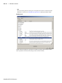
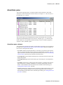
Assertions pane . . . . . . . . . . . . . . .
Assertions pane columns . . . . . . . . .
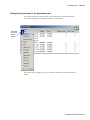
Hiding/showing columns in the Assertions pane
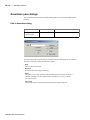
Assertions pane dialogs . . . . . . . . . .
Find in Assertions dialog . . . . . . . .
Configure assertions dialog . . . . . . .
.
.
.
.
.
.
.
.
.
.
.
.
.
.
.
.
.
.
.
.
.
.
.
.
.
.
.
.
.
.
.
.
.
.
.
.
.
.
.
.
.
.
.
.
.
.
.
.
.
.
.
.
.
.
.
.
.
.
.
.
.
.
.
.
.
.
.
.
.
.
.
.
.
.
.
.
.
.
.
.
.
.
.
.
.
.
.
.
.
.
.
.
.
.
.
.
.GR-116
.GR-116
.GR-118
.GR-119
.GR-119
.GR-120
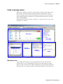
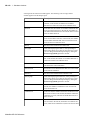
Code coverage panes . . . . .
Workspace pane . . . . .
Missed Coverage pane . .
Current Exclusions pane . .
Instance Coverage pane . .
Details pane . . . . . .
Objects pane toggle coverage
Code coverage toolbar . .
.
.
.
.
.
.
.
.
.
.
.
.
.
.
.
.
.
.
.
.
.
.
.
.
.
.
.
.
.
.
.
.
.
.
.
.
.
.
.
.
.
.
.
.
.
.
.
.
.
.
.
.
.
.
.
.
.
.
.
.
.
.
.
.
.
.
.
.
.
.
.
.
.
.
.
.
.
.
.
.
.
.
.
.
.
.
.
.
.
.
.
.
.
.
.
.
.
.
.
.
.
.
.
.
.
.
.
.
.
.
.
.
.
.
.
.
.
.
.
.
.
.
.
.
.
.
.
.
.
.
.
.
.
.
.
.
.
.
.
.
.
.
.
.
.
.
.
.
.
.
.
.
.
.
.
.
.
.
.
.
.
.
.
.
.
.
.
.
.
.
.
.
.
.
.
.
.
.
.
.
.
.
.
.
.
.
.
.
.
.
.
.
.GR-122
.GR-122
.GR-126
.GR-127
.GR-128
.GR-129
.GR-131
.GR-133
Dataflow window . . . . . .
Objects you can view . . .
Dataflow window menu bar
File menu . . . . . .
Edit menu . . . . .
View menu . . . . .
Navigate menu . . . .
Trace menu . . . . .
Tools menu . . . . .
.
.
.
.
.
.
.
.
.
.
.
.
.
.
.
.
.
.
.
.
.
.
.
.
.
.
.
.
.
.
.
.
.
.
.
.
.
.
.
.
.
.
.
.
.
.
.
.
.
.
.
.
.
.
.
.
.
.
.
.
.
.
.
.
.
.
.
.
.
.
.
.
.
.
.
.
.
.
.
.
.
.
.
.
.
.
.
.
.
.
.
.
.
.
.
.
.
.
.
.
.
.
.
.
.
.
.
.
.
.
.
.
.
.
.
.
.
.
.
.
.
.
.
.
.
.
.
.
.
.
.
.
.
.
.
.
.
.
.
.
.
.
.
.
.
.
.
.
.
.
.
.
.
.
.
.
.
.
.
.
.
.
.
.
.
.
.
.
.
.
.
.
.
.
.
.
.
.
.
.
.
.
.
.
.
.
.
.
.
.
.
.
.
.
.
.
.
.
.
.
.
.
.
.
.
.
.
.
.
.
.
.
.
.
.
.
.GR-134
.GR-134
.GR-135
.GR-135
.GR-135
.GR-136
.GR-136
.GR-137
.GR-137
Active Processes pane . . . . . . .
Process status . . . . . . . . .
Active Processes dialogs . . . .
Find in Active Processes dialog
ModelSim SE GUI Reference
.
.
.
.
GR-7
Window menu . . . . . .
Dataflow window toolbar . . .
Dataflow window dialogs . . .
Print dialog . . . . . . .
Print Postscript dialog . . .
Dataflow Page Setup dialog
Find in dataflow dialog . .
Dataflow Options dialog . .
Customize Toolbar dialog .
.
.
.
.
.
.
.
.
.
.
.
.
.
.
.
.
.
.
.
.
.
.
.
.
.
.
.
.
.
.
.
.
.
.
.
.
.
.
.
.
.
.
.
.
.
.
.
.
.
.
.
.
.
.
.
.
.
.
.
.
.
.
.
.
.
.
.
.
.
.
.
.
.
.
.
.
.
.
.
.
.
.
.
.
.
.
.
.
.
.
.
.
.
.
.
.
.
.
.
.
.
.
.
.
.
.
.
.
.
.
.
.
.
.
.
.
.
.
.
.
.
.
.
.
.
.
.
.
.
.
.
.
.
.
.
.
.
.
.
.
.
.
.
.
.
.
.
.
.
.
.
.
.
.
.
.
.
.
.
.
.
.
.
.
.
.
.
.
.
.
.
.
.
.
.
.
.
.
.
.
.
.
.
.
.
.
.
.
.
.
.
.
.
.
.
.
.
.
.GR-137
.GR-138
.GR-141
.GR-141
.GR-143
.GR-144
.GR-145
.GR-146
.GR-148
Functional Coverage pane . . . . . . . . . . . . . . . .
Functional Coverage window columns . . . . . . . . .
Hiding/showing columns in the Functional Coverage window
Functional Coverage pane dialogs . . . . . . . . . . .
Functional coverage reload dialog . . . . . . . . .
Functional coverage report dialog . . . . . . . . .
Find in Functional Coverage dialog . . . . . . . .
Configure cover directives dialog . . . . . . . . .
Functional coverage filter dialog . . . . . . . . . .
Customize Toolbar dialog . . . . . . . . . . . .
.
.
.
.
.
.
.
.
.
.
.
.
.
.
.
.
.
.
.
.
.
.
.
.
.
.
.
.
.
.
.
.
.
.
.
.
.
.
.
.
.
.
.
.
.
.
.
.
.
.
.
.
.
.
.
.
.
.
.
.
.
.
.
.
.
.
.
.
.
.
.
.
.
.
.
.
.
.
.
.
.
.
.
.
.
.
.
.
.
.
.
.
.
.
.
.
.
.
.
.
.
.
.
.
.
.
.
.
.
.
.GR-149
.GR-149
.GR-150
.GR-151
.GR-151
.GR-152
.GR-154
.GR-155
.GR-157
.GR-158
List window . . . . . . . . . . . .
Objects you can view . . . . . . .
List window menu bar . . . . . .
File menu . . . . . . . . . .
Edit menu . . . . . . . . .
View menu . . . . . . . . .
Tools menu . . . . . . . . .
Window menu . . . . . . . .
The List window context menu . . .
List window dialogs . . . . . . .
Open Dataset . . . . . . . .
Find in .list dialog . . . . . .
List Signal Search dialog . . . .
List Signal Properties dialog . .
Combine Selected Signals dialog
Modify Display Properties dialog
Customize Toolbar dialog . . .
.
.
.
.
.
.
.
.
.
.
.
.
.
.
.
.
.
.
.
.
.
.
.
.
.
.
.
.
.
.
.
.
.
.
.
.
.
.
.
.
.
.
.
.
.
.
.
.
.
.
.
.
.
.
.
.
.
.
.
.
.
.
.
.
.
.
.
.
.
.
.
.
.
.
.
.
.
.
.
.
.
.
.
.
.
.
.
.
.
.
.
.
.
.
.
.
.
.
.
.
.
.
.
.
.
.
.
.
.
.
.
.
.
.
.
.
.
.
.
.
.
.
.
.
.
.
.
.
.
.
.
.
.
.
.
.
.
.
.
.
.
.
.
.
.
.
.
.
.
.
.
.
.
.
.
.
.
.
.
.
.
.
.
.
.
.
.
.
.
.
.
.
.
.
.
.
.
.
.
.
.
.
.
.
.
.
.
.
.
.
.
.
.
.
.
.
.
.
.
.
.
.
.
.
.
.
.
.
.
.
.
.
.
.
.
.
.
.
.
.
.
.
.
.
.
.
.
.
.
.
.
.
.
.
.
.
.
.
.
.
.
.
.
.
.
.
.
.
.
.
.
.
.
.
.
.
.
.
.
.
.
.
.
.
.
.
.
.
.
.
.
.
.
.
.
.
.
.
.
.
.
.
.
.
.
.
.
.
.
.
.
.
.
.
.
.
.
.
.
.
.
.
.
.
.
.
.
.
.
.
.
.
.
.
.
.
.
.
.
.
.
.
.
.
.
.
.
.
.
.
.
.
.
.
.
.
.
.
.
.
.GR-159
.GR-159
.GR-160
.GR-160
.GR-160
.GR-161
.GR-161
.GR-161
.GR-161
.GR-162
.GR-162
.GR-162
.GR-163
.GR-165
.GR-167
.GR-168
.GR-171
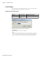
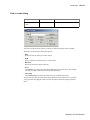
Locals pane . . . . . . . . . . . .
Locals dialogs . . . . . . . . . .
Change Selected Variable dialog
Find in Locals dialog . . . . .
.
.
.
.
.
.
.
.
.
.
.
.
.
.
.
.
.
.
.
.
.
.
.
.
.
.
.
.
.
.
.
.
.
.
.
.
.
.
.
.
.
.
.
.
.
.
.
.
.
.
.
.
.
.
.
.
.
.
.
.
.
.
.
.
.
.
.
.
.
.
.
.
.
.
.
.
.
.
.
.
.GR-172
.GR-173
.GR-173
.GR-174
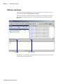
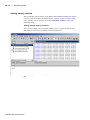
Memory windows . . . . . . . . . . .
Memories you can view . . . . . . .
Viewing memory contents . . . . . .
Direct address navigation . . . . . .
Splitting the memory contents window .
Memory popup menu commands . . .
Memory tab popup menu . . . .
Memory contents pane popup menus
Memory dialogs . . . . . . . . . .
.
.
.
.
.
.
.
.
.
.
.
.
.
.
.
.
.
.
.
.
.
.
.
.
.
.
.
.
.
.
.
.
.
.
.
.
.
.
.
.
.
.
.
.
.
.
.
.
.
.
.
.
.
.
.
.
.
.
.
.
.
.
.
.
.
.
.
.
.
.
.
.
.
.
.
.
.
.
.
.
.
.
.
.
.
.
.
.
.
.
.
.
.
.
.
.
.
.
.
.
.
.
.
.
.
.
.
.
.
.
.
.
.
.
.
.
.
.
.
.
.
.
.
.
.
.
.
.
.
.
.
.
.
.
.
.
.
.
.
.
.
.
.
.
.
.
.
.
.
.
.
.
.
.
.
.
.
.
.
.
.
.
.
.
.
.
.
.
.
.
.
.GR-175
.GR-176
.GR-177
.GR-178
.GR-178
.GR-179
.GR-179
.GR-179
.GR-181
ModelSim SE GUI Reference
GR-8
Table of Contents
Load Memory dialog . .
Save Memory dialog . .
Change Memory dialog .
Compare Memory dialog
Find dialog . . . . . .
Properties dialog . . . .
.
.
.
.
.
.
.
.
.
.
.
.
.
.
.
.
.
.
.
.
.
.
.
.
.
.
.
.
.
.
.
.
.
.
.
.
.
.
.
.
.
.
.
.
.
.
.
.
.
.
.
.
.
.
.
.
.
.
.
.
.
.
.
.
.
.
.
.
.
.
.
.
.
.
.
.
.
.
.
.
.
.
.
.
.
.
.
.
.
.
.
.
.
.
.
.
.
.
.
.
.
.
.
.
.
.
.
.
.
.
.
.
.
.
.
.
.
.
.
.
.
.
.
.
.
.
.
.
.
.
.
.
.
.
.
.
.
.
.GR-181
.GR-183
.GR-185
.GR-187
.GR-188
.GR-189
Objects pane . . . . . . . . . .
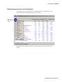
Filtering the objects list . . . .
Objects dialogs . . . . . . .
Force Selected Signal dialog
Define Clock dialog . . .
Find in Objects dialog . . .
Modify Breakpoints dialog .
.
.
.
.
.
.
.
.
.
.
.
.
.
.
.
.
.
.
.
.
.
.
.
.
.
.
.
.
.
.
.
.
.
.
.
.
.
.
.
.
.
.
.
.
.
.
.
.
.
.
.
.
.
.
.
.
.
.
.
.
.
.
.
.
.
.
.
.
.
.
.
.
.
.
.
.
.
.
.
.
.
.
.
.
.
.
.
.
.
.
.
.
.
.
.
.
.
.
.
.
.
.
.
.
.
.
.
.
.
.
.
.
.
.
.
.
.
.
.
.
.
.
.
.
.
.
.
.
.
.
.
.
.
.
.
.
.
.
.
.
.
.
.
.
.
.
.
.
.
.
.
.
.
.
.GR-190
.GR-191
.GR-192
.GR-192
.GR-194
.GR-196
.GR-197
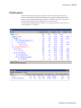
Profile panes . . . . . . . . . . . . . . .
Profile pane columns . . . . . . . . . .
Hiding/showing columns in the Profile panes
Profiler popup menu commands . . . . . .
Profiler toolbar . . . . . . . . . . . .
Profiler dialogs . . . . . . . . . . . .
Profile Report dialog . . . . . . . .
.
.
.
.
.
.
.
.
.
.
.
.
.
.
.
.
.
.
.
.
.
.
.
.
.
.
.
.
.
.
.
.
.
.
.
.
.
.
.
.
.
.
.
.
.
.
.
.
.
.
.
.
.
.
.
.
.
.
.
.
.
.
.
.
.
.
.
.
.
.
.
.
.
.
.
.
.
.
.
.
.
.
.
.
.
.
.
.
.
.
.
.
.
.
.
.
.
.
.
.
.
.
.
.
.
.
.
.
.
.
.
.
.
.
.
.
.
.
.
.GR-198
.GR-199
.GR-200
.GR-201
.GR-202
.GR-203
.GR-203
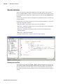
Source window . . . . . . . . . . . . . . . . . . . . .
Opening source files . . . . . . . . . . . . . . . . .
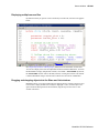
Displaying multiple source files . . . . . . . . . . . . .
Dragging and dropping objects into the Wave and List windows
Language templates . . . . . . . . . . . . . . . . .
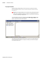
Setting file-line breakpoints . . . . . . . . . . . . . .
Checking object values and descriptions . . . . . . . . .
Finding and replacing in a Source window . . . . . . . .
Marking lines with bookmarks . . . . . . . . . . . . .
Customizing the Source window . . . . . . . . . . . .
Source window menus . . . . . . . . . . . . . . . .
.
.
.
.
.
.
.
.
.
.
.
.
.
.
.
.
.
.
.
.
.
.
.
.
.
.
.
.
.
.
.
.
.
.
.
.
.
.
.
.
.
.
.
.
.
.
.
.
.
.
.
.
.
.
.
.
.
.
.
.
.
.
.
.
.
.
.
.
.
.
.
.
.
.
.
.
.
.
.
.
.
.
.
.
.
.
.
.
.
.
.
.
.
.
.
.
.
.
.
.
.
.
.
.
.
.
.
.
.
.
.GR-205
.GR-205
.GR-206
.GR-206
.GR-207
.GR-209
.GR-209
.GR-210
.GR-210
.GR-211
.GR-212
Watch pane . . . . . . . . . . . . .
Objects you can view . . . . . . . .
Adding objects to the pane . . . . . .
Expanding objects to show individual bits
Grouping and ungrouping objects . . .
Saving and reloading format files . . .
Other Watch pane commands . . . . .
.
.
.
.
.
.
.
.
.
.
.
.
.
.
.
.
.
.
.
.
.
.
.
.
.
.
.
.
.
.
.
.
.
.
.
.
.
.
.
.
.
.
.
.
.
.
.
.
.
.
.
.
.
.
.
.
.
.
.
.
.
.
.
.
.
.
.
.
.
.
.
.
.
.
.
.
.
.
.
.
.
.
.
.
.
.
.
.
.
.
.
.
.
.
.
.
.
.
.
.
.
.
.
.
.
.
.
.
.
.
.
.
.
.
.
.
.
.
.
.
.
.
.
.
.
.
.
.
.
.
.
.
.
.GR-214
.GR-214
.GR-214
.GR-215
.GR-215
.GR-215
.GR-215
Wave window . . . . .
Wave window panes .
Objects you can view .
Wave window menu bar
File menu . . . .
Edit menu . . .
View menu . . .
Insert menu . . .
Format menu . .
Tools menu . . .
Window menu . .
.
.
.
.
.
.
.
.
.
.
.
.
.
.
.
.
.
.
.
.
.
.
.
.
.
.
.
.
.
.
.
.
.
.
.
.
.
.
.
.
.
.
.
.
.
.
.
.
.
.
.
.
.
.
.
.
.
.
.
.
.
.
.
.
.
.
.
.
.
.
.
.
.
.
.
.
.
.
.
.
.
.
.
.
.
.
.
.
.
.
.
.
.
.
.
.
.
.
.
.
.
.
.
.
.
.
.
.
.
.
.
.
.
.
.
.
.
.
.
.
.
.
.
.
.
.
.
.
.
.
.
.
.
.
.
.
.
.
.
.
.
.
.
.
.
.
.
.
.
.
.
.
.
.
.
.
.
.
.
.
.
.
.
.
.
.
.
.
.
.
.
.
.
.
.
.
.
.
.
.
.
.
.
.
.
.
.
.
.
.
.
.
.
.
.
.
.
.
.
.
.
.
.
.
.
.
.
.
.
.GR-217
.GR-219
.GR-220
.GR-222
.GR-222
.GR-223
.GR-223
.GR-224
.GR-224
.GR-225
.GR-225
ModelSim SE GUI Reference
.
.
.
.
.
.
.
.
.
.
.
.
.
.
.
.
.
.
.
.
.
.
.
.
.
.
.
.
.
.
.
.
.
.
.
.
.
.
.
.
.
.
.
.
.
.
.
.
.
.
.
.
.
.
.
.
.
.
.
.
.
.
.
.
.
.
.
.
.
.
.
.
.
.
.
.
.
GR-9
2-
Wave window toolbar . . . . . . .
Waveform editor toolbar . . . . .
Wave window dialogs . . . . . .
Open Dataset dialog . . . . .
Write Postscript dialog . . . .
Print dialog . . . . . . . . .
Page Setup dialog . . . . . .
Cursor Properties dialog . . . .
Find in .wave dialog . . . . .
Wave Signal Search dialog . . .
Force Selected Signal dialog . .
Define Clock dialog . . . . .
Wave Signal Properties dialog .
Wave Divider Properties dialog .
Bookmark Properties dialog . .
Start Comparison dialog . . . .
Add Signal Options dialog . . .
Add Comparison by Region dialog
Add Clocks dialog . . . . . .
Comparison Options dialog . . .
Modify Breakpoints dialog . . .
Bookmark Selection dialog . . .
Dataset Snapshot dialog . . . .
Combine Selected Signals dialog
Window Preferences dialog . .
.
.
.
.
.
.
.
.
.
.
.
.
.
.
.
.
.
.
.
.
.
.
.
.
.
.
.
.
.
.
.
.
.
.
.
.
.
.
.
.
.
.
.
.
.
.
.
.
.
.
.
.
.
.
.
.
.
.
.
.
.
.
.
.
.
.
.
.
.
.
.
.
.
.
.
.
.
.
.
.
.
.
.
.
.
.
.
.
.
.
.
.
.
.
.
.
.
.
.
.
.
.
.
.
.
.
.
.
.
.
.
.
.
.
.
.
.
.
.
.
.
.
.
.
.
.
.
.
.
.
.
.
.
.
.
.
.
.
.
.
.
.
.
.
.
.
.
.
.
.
.
.
.
.
.
.
.
.
.
.
.
.
.
.
.
.
.
.
.
.
.
.
.
.
.
.
.
.
.
.
.
.
.
.
.
.
.
.
.
.
.
.
.
.
.
.
.
.
.
.
.
.
.
.
.
.
.
.
.
.
.
.
.
.
.
.
.
.
.
.
.
.
.
.
.
.
.
.
.
.
.
.
.
.
.
.
.
.
.
.
.
.
.
.
.
.
.
.
.
.
.
.
.
.
.
.
.
.
.
.
.
.
.
.
.
.
.
.
.
.
.
.
.
.
.
.
.
.
.
.
.
.
.
.
.
.
.
.
.
.
.
.
.
.
.
.
.
.
.
.
.
.
.
.
.
.
.
.
.
.
.
.
.
.
.
.
.
.
.
.
.
.
.
.
.
.
.
.
.
.
.
.
.
.
.
.
.
.
.
.
.
.
.
.
.
.
.
.
.
.
.
.
.
.
.
.
.
.
.
.
.
.
.
.
.
.
.
.
.
.
.
.
.
.
.
.
.
.
.
.
.
.
.
.
.
.
.
.
.
.
.
.
.
.
.
.
.
.
.
.
.
.
.
.
.
.
.
.
.
.
.
.
.
.
.
.
.
.
.
.
.
.
.
.
.
.
.
.
.
.
.
.
.
.
.
.
.
.
.
.
.
.
.
.
.
.
.
.
.
.
.
.
.
.
.
.
.
.
.
.
.
.
.
.
.
.
.
.
.
.
.
.
.
.
.
.
.
.
.
.
.
.
.
.
.
.
.
.
.
.
.
.
.
.
.
.
.
.
.
.
.GR-226
.GR-228
.GR-231
.GR-231
.GR-232
.GR-234
.GR-236
.GR-238
.GR-239
.GR-240
.GR-242
.GR-242
.GR-243
.GR-247
.GR-248
.GR-249
.GR-250
.GR-251
.GR-252
.GR-253
.GR-255
.GR-256
.GR-257
.GR-259
.GR-261
Customizing the GUI layout . . . . . .
Moving, docking, and undocking panes
Zooming panes . . . . . . . . .
Columnar information display . . .
Quick access toolbars . . . . . . .
.
.
.
.
.
.
.
.
.
.
.
.
.
.
.
.
.
.
.
.
.
.
.
.
.
.
.
.
.
.
.
.
.
.
.
.
.
.
.
.
.
.
.
.
.
.
.
.
.
.
.
.
.
.
.
.
.
.
.
.
.
.
.
.
.
.
.
.
.
.
.
.
.
.
.
.
.
.
.
.
.
.
.
.
.
.
.
.
.
.
.
.
.
.
.
.
.
.
.
.
.GR-264
.GR-264
.GR-266
.GR-268
.GR-269
Creating and managing breakpoints . . . . . . . . . . . . . . . . . . . . . . . .GR-270
Signal breakpoints . . . . . . . . . . . . . . . . . . . . . . . . . . . . .GR-270
File-line breakpoints . . . . . . . . . . . . . . . . . . . . . . . . . . . .GR-270
2 - ModelSim GUI changes (UM-272)
Main window changes . . . . . . . . .
Panes and Windows . . . . . . . .
Multiple document interface (MDI) frame
Context Sensitivity . . . . . . . . .
File menu . . . . . . . . . . . .
View menu . . . . . . . . . . . .
Simulate menu . . . . . . . . . .
Tools menu . . . . . . . . . . . .
Window menu . . . . . . . . . .
.
.
.
.
.
.
.
.
.
.
.
.
.
.
.
.
.
.
.
.
.
.
.
.
.
.
.
.
.
.
.
.
.
.
.
.
.
.
.
.
.
.
.
.
.
.
.
.
.
.
.
.
.
.
.
.
.
.
.
.
.
.
.
.
.
.
.
.
.
.
.
.
.
.
.
.
.
.
.
.
.
.
.
.
.
.
.
.
.
.
.
.
.
.
.
.
.
.
.
.
.
.
.
.
.
.
.
.
.
.
.
.
.
.
.
.
.
.
.
.
.
.
.
.
.
.
.
.
.
.
.
.
.
.
.
.
.
.
.
.
.
.
.
.
.
.
.
.
.
.
.
.
.
.
.
.
.
.
.
.
.
.
.
.
.
.
.
.
.
.
.
UM-273
UM-273
UM-274
UM-274
UM-275
UM-278
UM-279
UM-280
UM-281
List window changes . . . . . . . . . . . . . . . . . . . . . . . . . . . . . UM-282
File menu . . . . . . . . . . . . . . . . . . . . . . . . . . . . . . . UM-282
Memory window changes . . . . . . . . . . . . . . . . . . . . . . . . . . . UM-283
File menu . . . . . . . . . . . . . . . . . . . . . . . . . . . . . . . UM-284
ModelSim SE GUI Reference
GR-10
Table of Contents
Edit menu . . . . . . . . . . . . . . . . . . . . . . . . . . . . . . . UM-285
View menu . . . . . . . . . . . . . . . . . . . . . . . . . . . . . . . UM-286
Signals (Objects) window . . . . . . . . . . . . . . . . . . . . . . . . . . . UM-287
File menu . . . . . . . . . . . . . . . . . . . . . . . . . . . . . . . UM-287
Edit menu . . . . . . . . . . . . . . . . . . . . . . . . . . . . . . . UM-288
Source window changes . . . . . . . . . . . . . . . . . . . . . . . . . . . UM-289
File menu . . . . . . . . . . . . . . . . . . . . . . . . . . . . . . . UM-289
View menu . . . . . . . . . . . . . . . . . . . . . . . . . . . . . . . UM-290
Variables (Locals) window . . . . . . . . . . . . . . . . . . . . . . . . . . UM-291
Edit menu . . . . . . . . . . . . . . . . . . . . . . . . . . . . . . . UM-291
3 - Setting GUI preferences (GR-292)
ModelSim GUI preferences . . . . . . . . . . . . . . . . . . . . . . . . . . .GR-293
Setting variables from the GUI . . . . . . . . . . . . . . . . . . . . . . . .GR-294
Setting variables from the command line . . . . . . . . . . . . . . . . . . . .GR-294
Index (GR-276)
ModelSim SE GUI Reference
GR-11
2-
ModelSim SE GUI Reference
GR-12
1 - Simulator windows
Chapter contents
Introduction . . . . . . . .
Design object icons and their meaning
.
.
.
.
.
.
.
.
.
.
.
.
.
.
. GR-14
. GR-15
Setting fonts . . . . . . .
Font scaling . . . . . .
Controlling fonts in an X-session .
.
.
.
.
.
.
.
.
.
.
.
.
.
.
.
.
.
.
.
.
.
.
.
.
. GR-16
. GR-16
. GR-16
Main window . . . .
Main window menu bar
Main window toolbar .
Main window status bar
Main window dialogs .
.
.
.
.
.
.
.
.
.
.
.
.
.
.
.
.
.
.
.
.
.
.
.
.
.
.
.
.
.
.
.
.
.
.
.
.
.
.
.
.
.
.
.
.
.
.
.
.
.
.
.
.
.
.
.
.
.
.
.
.
Active Processes pane . . .
Active Processes dialogs .
.
.
.
.
.
.
.
.
.
.
.
.
.
.
.
.
.
.
.
.
. GR-114
. GR-115
Assertions pane
. . .
Assertions pane dialogs
.
.
.
.
.
.
.
.
.
.
.
.
.
.
.
.
.
.
.
.
.
.
.GR-116
.GR-119
Code coverage panes . .
Code coverage toolbar
.
.
.
.
.
.
.
.
.
.
.
.
.
.
.
.
.
.
.
.
.
.
. GR-122
.GR-133
.
.
.
.
.
.
.
.
.
.
.
.
.
.
.
.
.
.
.
.
.
.
.
.
.
.
.
.
.
.
.
.
.
.
.
.
.
.
.
.
. GR-134
. GR-135
. GR-138
.GR-141
Functional Coverage pane . . . .
Functional Coverage pane dialogs
.
.
.
.
.
.
.
.
.
.
.
.
.
.
.
.
. GR-149
.GR-151
List window . . . .
List window menu bar.
List window dialogs .
.
.
.
.
.
.
.
.
.
.
.
.
.
.
.
.
.
.
.
.
.
.
.
.
.
.
.
.
.
.
.
.
.
. GR-159
. GR-160
.GR-162
Locals pane. . .
Locals dialogs .
.
.
.
.
.
.
.
.
.
.
.
.
.
.
.
.
.
.
.
.
.
.
. GR-172
.GR-173
Memory windows . . . . . .
Memory popup menu commands .
Memory dialogs . . . . .
.
.
.
.
.
.
.
.
.
.
.
.
.
.
.
.
.
.
.
.
.
.
.
.
. GR-175
. GR-179
. GR-181
Objects pane . .
Objects dialogs
.
.
.
.
.
.
.
.
.
.
.
.
.
.
.
.
.
.
. GR-190
. GR-192
Profile panes . . . . . .
Profiler popup menu commands
Profiler dialogs . . . .
Profiler toolbar . . . .
.
.
.
.
.
.
.
.
.
.
.
.
.
.
.
.
.
.
.
.
.
.
.
.
.
.
.
.
.
.
.
.
.
.
.
.
. GR-198
. GR-201
. GR-203
. GR-202
Source window. . . .
Source window menus
.
.
.
.
.
.
.
.
.
.
.
.
.
.
.
.
.
.
. GR-205
.GR-212
Dataflow window . . . .
Dataflow window menu bar
Dataflow window toolbar .
Dataflow window dialogs .
.
.
.
.
.
.
.
.
.
.
.
.
.
.
.
.
GR-17
GR-24
GR-38
GR-23
GR-42
ModelSim SE GUI Reference
GR-13
1 - Simulator windows
Watch pane. . . . . . . . . .
Adding objects to the pane . . . .
Expanding objects to show individual bits
Grouping and ungrouping objects. . .
.
.
.
.
.
.
.
.
.
.
.
.
.
.
.
.
.
.
.
.
.
.
.
.
. GR-214
. GR-214
. GR-215
. GR-215
Wave window . . . .
Wave window menu bar
Wave window toolbar .
Wave window dialogs.
.
.
.
.
.
.
.
.
.
.
.
.
.
.
.
.
.
.
.
.
.
.
.
.
.
.
.
.
. GR-217
. GR-222
. GR-226
. GR-231
Customizing the GUI layout . . . .
Moving, docking, and undocking panes
Columnar information display . .
Quick access toolbars . . . . .
.
.
.
.
.
.
.
.
.
.
.
.
.
.
.
.
.
.
.
.
.
.
.
.
.
.
.
.
. GR-264
.GR-264
. GR-268
. GR-269
Creating and managing breakpoints
.
.
.
.
.
.
.
. GR-270
.
.
.
.
.
.
.
.
.
.
.
.
.
.
.
.
.
.
This chapter describes the various windows, menus, and commands that comprise the
ModelSim Graphical User Interface (GUI). Chapters earlier in the User’s Manual also
discuss the GUI but are organized more in a task-based format as opposed to the reference
structure of this appendix.
ModelSim SE GUI Reference
Introduction
GR-14
Introduction
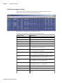
ModelSim’s graphical user interface (GUI) consists of various windows that give access to
parts of your design and numerous debugging tools. Some of the windows display as panes
within the ModelSim Main window, some display as windows in the Multiple Document
Interface (MDI) frame, and some display as standalone windows.
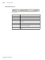
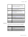
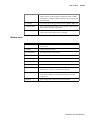
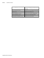
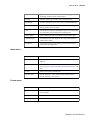
The following table summarizes all of the available windows and panes.
Window/pane name
Description
More details
Main
central GUI access point
"Main window" (GR-17)
Active Processes
displays all processes that are scheduled to run
during the current simulation cycle
"Active Processes pane" (GR-114)
Assertions
manages PSL assertions
"Assertions pane" (GR-116)
Code coverage
a collection of panes that display code coverage
data
"Code coverage panes" (GR-122)
Dataflow
displays "physical" connectivity and lets you
trace events (causality)
"Dataflow window" (GR-134)
Functional Coverage
manages PSL cover directives
"Functional Coverage pane" (GR149)
List
shows waveform data in a tabular format
"List window" (GR-159)
Locals
displays data objects that are immediately
visible at the current PC of the selected process
"Locals pane" (GR-172)
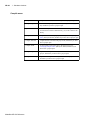
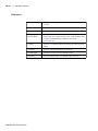
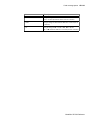
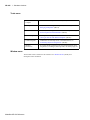
ModelSim SE GUI Reference
GR-15
1 - Simulator windows
Window/pane name
Description
More details
Memory
a Workspace tab and MDI windows that show
memories and their contents
"Memory windows" (GR-175)
Watch
displays signal or variable values at the current
simulation time
"Watch pane" (GR-214)
Objects
displays all declared data objects in the current
scope
"Objects pane" (GR-190)
Profile
two panes that display performance and
memory profiling data
"Profile panes" (GR-198)
Source
a text editor for viewing and editing HDL,
SystemC, DO, etc. files
"Source window" (GR-205)
Transcript
keeps a running history of commands and
messages and provides a command-line
interface
"Transcript" (GR-19)
Wave
displays waveforms
"Wave window" (GR-217)
Workspace
provides easy access to projects, libraries,
compiled design units, etc.
"Workspace" (GR-18)
The windows and panes are customizable in that you can position and size them as you see
fit, and ModelSim will remember your settings upon subsequent invocations. See
"Customizing the GUI layout" (GR-264) for more details.
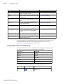
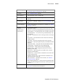
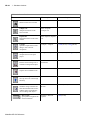
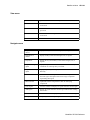
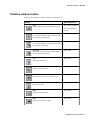
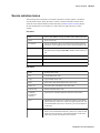
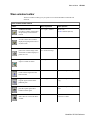
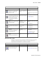
Design object icons and their meaning
The color and shape of icons convey information about the language and type of a design
object. Here is a list of icon colors and the languages they indicate:
icon color
language
light blue
Verilog
dark blue
VHDL
green
SystemC
magenta
PSL
orange
virtual object
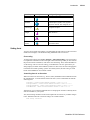
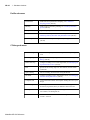
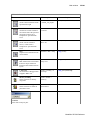
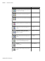
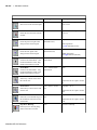
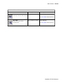
Here is a list of icon shapes and the design object types they indicate:
icon shape
square
ModelSim SE GUI Reference
example
design object type
blocks (entity/architecture, module, SC
module, etc.)
Introduction
icon shape
example
GR-16
design object type
circle
process
diamond
valued object (signals, nets, registers,
SystemC channel, PSL endpoint, etc.)
caution sign
comparison object
triangle
PSL assertion
up arrow
PSL cover directive
diamond with
red dot
an editable waveform created with the
waveform editor
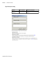
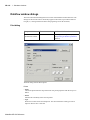
Setting fonts
You may need to adjust font settings to accommodate the aspect ratios of wide screen and
double screen displays or to handle launching ModelSim from an X-session.
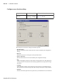
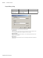
Font scaling
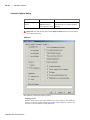
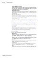
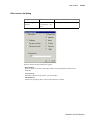
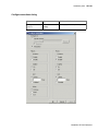
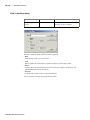
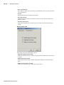
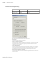
To change font scaling, select Tools > Options > Adjust Font Scaling. You’ll need a ruler
to complete the instructions in the lower right corner of the dialog. When you have entered
the pixel and inches information, click OK to close the dialog. Then, restart ModelSim to
see the change. This is a one time setting; you shouldn't have to set it again unless you
change display resolution or the hardware (monitor or video card). The font scaling applies
to Windows and UNIX operating systems. On UNIX systems, the font scaling is stored
based on the $DISPLAY environment variable.
Controlling fonts in an X-session
When executed via an X-session (e.g., Exceed, VNC), ModelSim uses font definitions from
the .Xdefaults file. To ensure that the fonts look correct, create a .Xdefaults file with the
following lines:
vsim*Font: -adobe-courier-medium-r-normal--*-120-*-*-*-*-*
vsim*SystemFont: -adobe-courier-medium-r-normal--*-120-*-*-*-*-*
vsim*StandardFont: -adobe-courier-medium-r-normal--*-120-*-*-*-*-*
vsim*MenuFont: -adobe-courier-medium-r-normal--*-120-*-*-*-*-*
Alternatively, you can choose a different font. Use the program "xlsfonts" to identify which
fonts are available on your system.
Also, the following command can be used to update the X resources if you make changes
to the .Xdefaults and wish to use those changes on a UNIX machine:
xrdb -merge .Xdefaults
ModelSim SE GUI Reference
GR-17
1 - Simulator windows
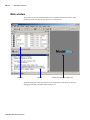
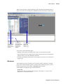
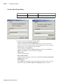
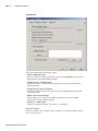
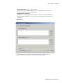
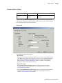
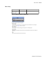
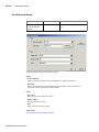
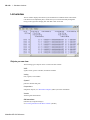
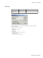
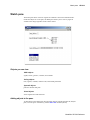
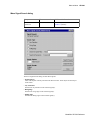
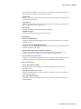
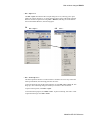
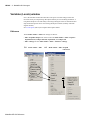
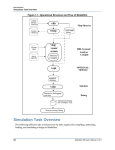
Main window
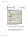
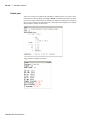
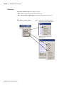
The primary access point in the ModelSim GUI is called the Main window. Here is what
the Main window looks like the very first time you start the tool:
Workspace
Transcript
Multiple document interface (MDI) pane
The Main window provides convenient access to design libraries and objects, source files,
debugging commands, simulation status messages, etc.
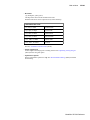
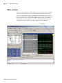
ModelSim SE GUI Reference
Main window
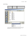
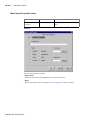
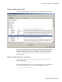
GR-18
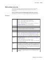
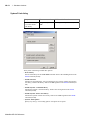
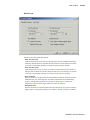
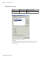
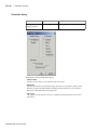
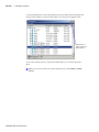
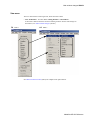
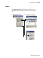
When you load a design, or bring up debugging tools, ModelSim adds additional panes or
opens new windows. For example, here is the Main window after loading a simple design.
Workspace tabs
organize design
elements in a
hierarchical tree
structure
The Transcript
pane reports status
and provides a
command-line
interface
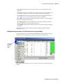
The Objects pane
displays data
objects in the
current scope
Notice some of the elements that appear:
• Workspace tabs organize and display design objects in a hierarchical tree format
• The Transcript pane tracks command history and messages and provides a command-line
interface where you can enter ModelSim commands
• The Objects pane displays design objects such as signals, nets, generics, etc. in the current
design scope
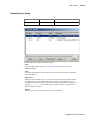
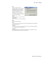
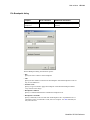
Workspace
The Workspace provides convenient access to projects, libraries, design files, compiled
design units, simulation/dataset structures, and Waveform Comparison objects. It can be
hidden or displayed by selecting View > Workspace (Main window).
The Workspace can display the types of tabs listed below.
• Project tab
Shows all files that are included in the open project. See Chapter 2 - Projects in the
ModelSim User’s Manual for details.
ModelSim SE GUI Reference
GR-19
1 - Simulator windows
• Library tab
Shows design libraries and compiled design units. See "Managing library contents" (UM61) for details.
• Structure tabs
Shows a hierarchical view of the active simulation and any open datasets. There is one
tab for the current simulation (named "sim") and one tab for each open dataset. See
"Viewing dataset structure" (UM-228) for details.
An entry is created by each object within the design. When you select a region in a
structure tab, it becomes the current region and is highlighted. The Source window (GR205) and Objects pane (GR-190) change dynamically to reflect the information for that
region. This feature provides a useful method for finding the source code for a selected
region because the system keeps track of the pathname where the source is located and
displays it automatically, without the need for you to provide the pathname.
Also, when you select a region in the structure pane, the "Active Processes pane" (GRis updated. The Active Processes window will in turn update the Locals pane (GR172).
114)
• Files tab
Shows the source files for the loaded design.
You can disable the display of this tab by setting the PrefMain(ShowFilePane) preference
variable to 0. See "ModelSim GUI preferences" (GR-293) for information on setting
preference variables.
• Memories tab
Shows a hierarchical list of all memories in the design. To display this tab, select View
> Debug Windows > Memory. When you select a memory on the tab, a memory
contents page opens in the MDI frame. See "Memory windows" (GR-175).
• Compare tab
Shows comparison objects that were created by doing a waveform comparison. See
Chapter 9 - Waveform analysis for details.
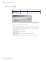
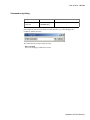
Transcript
The Transcript portion of the Main window maintains a running history of commands that
are invoked and messages that occur as you work with ModelSim. When a simulation is
running, the Transcript displays a VSIM prompt, allowing you to enter command-line
commands from within the graphic interface.
You can scroll backward and forward through the current work history by using the vertical
scrollbar. You can also use arrow keys to recall previous commands, or copy and paste
using the mouse within the window (see "Main and Source window mouse and keyboard
shortcuts" (UM-607) for details).
Saving the transcript file
Variable settings determine the filename used for saving the transcript. If either
PrefMain(file) in the modelsim.tcl file or TranscriptFile in the modelsim.ini file is set,
then the transcript output is logged to the specified file. By default the TranscriptFile
variable in modelsim.ini is set to transcript. If either variable is set, the transcript contents
are always saved and no explicit saving is necessary.
ModelSim SE GUI Reference
Main window
GR-20
If you would like to save an additional copy of the transcript with a different filename, click
in the Transcript pane and then select File > Save As, or File > Save. The initial save must
be made with the Save As selection, which stores the filename in the Tcl variable
PrefMain(saveFile). Subsequent saves can be made with the Save selection. Since no
automatic saves are performed for this file, it is written only when you invoke a Save
command. The file is written to the specified directory and records the contents of the
transcript at the time of the save.
Using the saved transcript as a macro (DO file)
Saved transcript files can be used as macros (DO files). See the do command (CR-153) for
more information.
Disabling creation of the transcript file
You can disable the creation of the transcript file by using the following ModelSim
command immediately after ModelSim starts:
transcript file ""
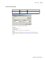
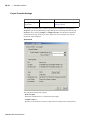
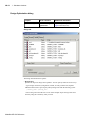
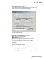
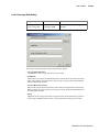
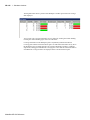
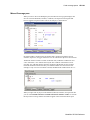
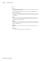
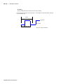
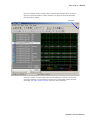
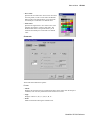
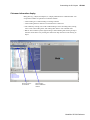
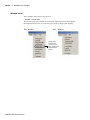
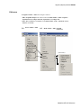
Multiple document interface (MDI) frame
The MDI frame is an area in the Main window where source editor, memory content, and
wave windows display. The frame allows multiple windows to be displayed
simultaneously, as shown below. A tab appears for each window.
Object name
Window tabs
ModelSim SE GUI Reference
GR-21
1 - Simulator windows
The object name is displayed in the title bar at the top of the window. You can switch
between the windows by clicking on a tab.
ModelSim SE GUI Reference
Main window
GR-22
Organizing windows with tab groups
The MDI can quickly become unwieldy if many windows are open. You can create "tab
groups" to help organize the windows. A tab group is a collection of tabs that are separated
from other groups of tabs.
The graphic below shows how the collection of files in the picture above could be
organized into two tab groups.
The commands for creating and organizing tab groups are accessed by right-clicking on any
window tab. The table below describes the commands associated with tab groups:
Command
Description
New Tab Group
Creates a new tab group containing the selected tab
Move Next Group
Moves the selected tab to the next group in the MDI
Move Prev Group
Moves the selected tab to the previous group in the MDI
View > Vertical /
Horizontal
Arranges tab groups top-to-bottom (vertical) or right-to-left
(horizontal)
Note that you can also move the tabs within a tab group by dragging them with the middle
mouse button.
ModelSim SE GUI Reference
GR-23
1 - Simulator windows
Main window status bar
Fields at the bottom of the Main window provide the following information about the
current simulation:
ModelSim SE GUI Reference
Field
Description
Project
name of the current project
Now
the current simulation time
Delta
the current simulation iteration number
Profile Samples
the number of profile samples collected during the current
simulation
Memory
the total memory used during the current simulation
environment
name of the current context (object selected in the active
Structure tab of the Workspace)
line/column
line and column numbers of the cursor in the active Source
window
Main window
GR-24
Main window menu bar
The following commands are available from the Main window menu bar. Many of the
commands become enabled/disabled depending upon which pane of the window is
currently active.
Some commands behave differently depending upon which window pane is active. For
example, if a Source window is active, the File > Open command opens a standard Open
dialog. However, if a memory list is active, the command opens the Load Memory dialog.
File menu
New
provides these options:
Folder – create a new folder in the current directory
Source – create a VHDL, Verilog, or Other source file
Project – create a new project
Library – create a new design library and mapping; see "Create a New
Library dialog" (GR-43)
Window – create a new window of the specified type
Open
open a file; specify type by clicking Files of Type drop-down list
Load
executes or loads a previously saved format file (e.g. wave.do,
waveedit.do, watch.do) in the Wave or Watch windows
Close
close a file or simulation
Import
provides these options:
Library – import FPGA libraries; see "Importing FPGA libraries" (UM-69)
EVCD – import a previously saved extended EVCD file; see "Signal
mapping and importing EVCD files" (GR-295); this item is enabled only
when a Wave window is active in the MDI frame of the Main window
Export
provides these options:
Waveform – export a created waveform; see "Exporting waveforms to a
stimulus file" (GR-294);
Image – saves a bitmap image of the Wave window.
These items are enabled only when a Wave window is active in the MDI
frame of the Main window
Save
saves datasets, waveform formats, or waveform edits – depending upon
which pane is active. If the Wave window is active in the MDI frame, this
command will open the Save Format dialog, which will allow the user to
save waveform formats, waveform edits, or both. If the Workspace pane
is active and the sim tab selected, this command allows the user to save
the current dataset as a .wlf file.
Save As
save a file with a new name; the file to be saved depends upon which pane
is active (e.g., if the Transcript pane is active, this command saves the
transcript)
ModelSim SE GUI Reference
GR-25
1 - Simulator windows
Report
produce a textual report from the active pane
Change
Directory
change to a different working directory; disabled if you have a project or
dataset open or a simulation running
Use Source
specify an alternative file to use for the current source file; this alternative
source mapping exists for the current simulation only
Source
Directory
add to a list of directories to search for source files; you can set this
permanently using the SourceDir variable in the modelsim.tcl file
Environment
provides different options depending upon which pane is selected:
Follow Current Dataset – update the Objects pane based on the current
dataset
Fix to dataset <name> – fix the Objects pane content to a specific dataset
Follow Process Selection – update the Locals pane content based on the
selection in the "Active Processes pane" (GR-114)
Fix to Current Process – fix the Locals pane content to the current
process; do not update
Follow Context Selection – update the pane contents based upon the
selection in the structure tab of the Workspace
Fix to Current Context – maintain the current view; do not update
ModelSim SE GUI Reference
Add to
Project
provides these options:
New File – add new files to the open Project; see "Step 2 — Adding items
to the project" (UM-41)
Existing File – add existing files to the open Project; see "Step 2 —
Adding items to the project" (UM-41)
Simulation Configuration – add an object representing a design unit(s)
and its associated simulation options; see "Creating a Simulation
Configuration" (UM-48)
Folder – add an organization folder to the current project; see "Organizing
projects with folders" (UM-50)
Page Setup
configure page settings for printing waveforms; this item is enabled only
when a wave window is active in the MDI frame of the Main window
(Windows only)
Print
print the contents of the Transcript pane, a Source window, or an
embedded wave window
Print
Postscript
save or print the active Source file or wave window as a Postscript file
(Windows only)
Recent
Directories
displays a list of the most recent working directories
Recent
Projects
displays a list of the most recent projects
Quit
quit ModelSim
Main window
GR-26
Edit menu
Undo
undo the last edit
Redo
redo the previously undone edit
Cut
cut the selected text
Copy
copy the selected text
Paste
paste the previously cut or copied text
Delete
deletes an object from the active Wave window in the MDI frame
Clear
clear the Transcript pane
Select All
select all text in the active window
Unselect All
deselect all text in the active window
Expand
provides these options:
Expand Selected – expand the hierarchy of the selected instance
Collapse Selected – collapse the hierarchy of the selected instance
Expand All – expand the hierarchy of all instances in the active
window
Collapse All – collapse the hierarchy of all instances in the active
window
Advanced
provides these options:
Force – force a value on the item selected in the Objects pane; see
"Force Selected Signal dialog" (GR-192)
Noforce – cancel a previous force command
Clock – define a clock; see "Define Clock dialog" (GR-194)
Change – change the value of the selected object
Comment/Uncomment Selected – add or remove comment
characters from the lines selected in the active Source window
Examine – display the current value of the object selected in the
active Source window; same as the examine (CR-164) command
Describe – display information about the object selected in the
active Source window; same as the describe command (CR-149)
Drivers – list the names of all drivers of the object selected in the
active Source window
Readers – list the names of all readers of the object selected in the
active Source window
Wave
this menu is enabled only when a wave window is active in the
MDI frame of the Main window; most of the options on this menu
relate to Waveform Editor (see "Editing waveforms" (GR-290);
Edit Cursor – edit the name or time of the selected cursor
Delete Cursor – delete the selected cursor
Wave Signal Search – search the wave window for a signal name
or value, or an expression
ModelSim SE GUI Reference
GR-27
1 - Simulator windows
Find
search the active window for the specified text string
Replace
find and replace text in the active window
Find in Files
search for text in saved files
Previous Coverage
Miss
find the previous line with missed coverage in the active Source
window; see "Viewing coverage data in the Source window" (UM342)
Next Coverage Miss
find the next line with missed coverage in the active Source
window; see "Viewing coverage data in the Source window" (UM342)
View menu
Debug Windows
open various debugging windows/panes
Sort
sort the Objects or Locals pane
Filter
select the type of objects displayed in the Objects, Locals, or
Memory list panes
Justify
justify left or right the object names in the Locals window
Split screen
split the active memory contents window; see "Splitting the
memory contents window" (GR-178)
Datasets
open the Dataset Browser to open, close, rename, or activate a
dataset
Wave
this menu is enabled only when a wave window is active in the
MDI frame of the Main window
provides these options:
Object Declaration – open the source file in the Source window
and highlight the declaration for the currently selected object
Refresh Display – clear the Wave window, empty the file cache,
and rebuild the window from scratch
Zoom – choose various zoom commands
Mouse Mode – toggle mouse pointer between Select Mode (click
left mouse button to select, drag with middle mouse button to
zoom) and Zoom Mode (drag with left mouse button to zoom,
click middle mouse button to select)
Cursors – choose a cursor to go to from a list of available cursors
Bookmarks – choose a bookmark to go to from a list of available
bookmarks
See "Code coverage panes" (GR-122) for details on these panes.
ModelSim SE GUI Reference
Main window
Code Coverage
GR-28
provides these options:
Current Exclusions – hide or show the Exclusions pane
Missed Coverage – hide or show the Missed Coverage pane
Instance Coverage – hide or show the Instance Coverage pane
Details – hide or show the Details pane
See "Code coverage panes" (GR-122) for details on these panes.
Profile
provides these options:
View – hide or show Profile pane
View Details – hide or show Profile Details pane
Source
provides these options:
Show line numbers–toggle display of line numbers
Show language templates–toggle display of the Language
templates (GR-207) pane
Read Only–toggles read only status of selected source file
Workspace
hide or show the Workspace (GR-18) pane
Show Tabs
toggle display of window tabs in MDI frame
Tabbed MDI
toggle MDI frame mode from tab-based mode to floating window
mode; see "Multiple document interface (MDI) frame" (GR-20) for
more information
Goto
jump to the specified line number or memory address
Encoding
select from alphabetical list of encoding names that enable proper
display of character representations used by various operating
systems or file systems, such as Unicode, ASCII, or Shift-JIS.
Project Settings
show information about the open project
Properties
show information about the object selected in the Workspace
Format menu
The options on this menu are enabled only when a wave window is active in the MDI frame
of the Main window. To view a wave window in the MDI frame, use the view mdiwave
command.
Radix
set the selected objects’ radix
Format
set the waveform format for the selected objects – Literal, Logic,
Event, Analog
Color
set the color for the selected objects from a color palette
Height
set the waveform height in pixels for the selected objects
ModelSim SE GUI Reference
GR-29
1 - Simulator windows
Compile menu
Compile
Compile Options
compile source files; not enabled if you have a project open
set various compile options; see "Compiler Options dialog" (GRdisabled if you have a project open
65);
ModelSim SE GUI Reference
SystemC Link
collects the object files created in the different design libraries,
and uses them to build a shared library (.so) in the current work
library
Compile All
compile all files in the open project; see "Step 3 — Compiling the
files" (UM-43) for details; disabled if you don’t have a project open
Compile Selected
compile the files selected in the project tab; disabled if you don’t
have a project open
Compile Order
set the compile order of the files in the open project; see
"Changing compile order" (UM-46) for details; disabled if you
don’t have a project open
Compile Report
report on the compilation history of the selected file(s) in the
project; disabled if you don’t have a project open
Compile Summary
report on the compilation history of all files in the project;
disabled if you don’t have a project open
Main window
GR-30
Simulate menu
Design
Optimization
open the Design Optimization dialog to configure simulation
optimizations
Start Simulation
load the selected design unit; see "Start Simulation dialog" (GR-81)
Runtime Options
set various simulation runtime options; see "Runtime Options
dialog" (GR-90)
Run
provides these options:
Run <default> – run simulation for one default run length; change
the run length with Simulate > Runtime Options, or use the Run
Length text box on the toolbar
Run -All – run simulation until you stop it; see also the run
command (CR-254)
Continue – continue the simulation; see also the run command
(CR-254) and the -continue option
Run -Next – run to the next event time
Step – single-step the simulator; see also the step command (CR274)
Step -Over – execute without single-stepping through a
subprogram call
Restart – reload the design elements and reset the simulation time
to zero; only design elements that have changed are reloaded; you
specify whether to maintain the following after restart–List and
Wave window environment, breakpoints, logged signals, virtual
definitions, and assertion and functional coverage settings; see
also the restart command (CR-248)
Break
stop the current simulation run
End Simulation
quit the current simulation run
Wave
add objects from the selected pane to the Wave window; objects
vary depending on which pane is active–for example, if the
Assertions pane is selected, you can add assertions, whereas if the
Objects pane is selected, you can add signals
List
add objects from the selected pane to the List window; objects
vary depending on which pane is active–for example, if the
Assertions pane is selected, you can add assertions, whereas if the
Objects pane is selected, you can add signals
Add menu
ModelSim SE GUI Reference
GR-31
1 - Simulator windows
Log
add objects from the selected pane to the active log file; objects
vary depending on which pane is active–for example, if the
Assertions pane is selected, you can add assertions, whereas if the
Objects pane is selected, you can add signals
Divider
insert a divider in the Wave window; this item is enabled only
when a Wave window is active in the MDI frame of the Main
window
Breakpoint
add a breakpoint on the selected signal; see "Signal breakpoints"
(GR-270); this item is enabled only when a wave window is active
in the MDI frame of the Main window
Bookmark
add a bookmark with the current zoom range and scroll location;
see "Saving zoom range and scroll position with bookmarks" (UM250); this item is enabled only when a wave window is active in
the MDI frame of the Main window
Cursor
add a cursor to the Wave window; "Saving zoom range and scroll
position with bookmarks" (UM-250); this item is enabled only
when a wave window is active in the MDI frame of the Main
window
Window Pane
split the pathname, values and waveform window panes to
provide room for a new waveset; this item is enabled only when a
wave window is active in the MDI frame of the Main window
Waveform
Compare
see "Waveform Compare sub-menu" (GR-33)
Code Coverage
see "Code Coverage sub-menu" (GR-34)
Functional
Coverage
see "Functional Coverage sub-menu" (GR-34)
Toggle Coverage
add toggle coverage tracking to the Objects pane; see "Enabling
Toggle coverage" (UM-344)
Profile
see "Profile sub-menu" (GR-35)
Breakpoints
open the Breakpoints dialog box; see "Setting file-line
breakpoints" (GR-209) for details
Bookmarks
add, edit, delete, and goto bookmarks; see "Saving zoom range
and scroll position with bookmarks" (UM-250)
Dataset Snapshot
enable periodic saving of simulation data to a WLF file; see
"Saving at intervals with Dataset Snapshot" (UM-231)
Tools menu
ModelSim SE GUI Reference
Main window
Combine Signals
combine the selected objects into a user-defined bus; see
"Combining objects/creating busses" (UM-265)
C Debug
see "C Debug sub-menu" (GR-35)
Execute Macro
call and execute a .do or .tcl macro file
Macro Helper
GR-32
UNIX only - invoke the Macro Helper tool; see "Macro helper"
(UM-494)
Tcl Debugger
invoke the Tcl debugger, TDebug; see "The Tcl Debugger" (UM495)
TclPro Debugger
invoke TclPro Debugger by Scriptics®, if installed; see "TclPro
Debugger" (UM-499)
Options
(all options are set
for the current
session only)
provides these options:
Adjust Font Scaling – set font scaling factor when using dual
monitors; you must restart ModelSim after setting the font scaling
Transcript File – set a transcript file to save for this session only
Command History – set a file for saving command history only,
no comments
Save File – set filename for Save Transcript, and Save Transcript
As
Saved Lines – limit the number of lines saved in the transcript
(default is 5000)
Line Prefix – specify the comment prefix for the transcript
Update Rate – specify the update frequency for the Main window
status bar
ModelSim Prompt – change the title of the ModelSim prompt
VSIM Prompt – change the title of the VSIM prompt
Paused Prompt – change the title of the Paused prompt
HTML Viewer – specify the path to your browser; used for
displaying online help
PDF Viewer – specify the path to your PDF viewer; used for
displaying documentation
Examine Now – sets the examine command to read values at the
current simulation time
Examine Current Cursor – sets the examine command to read
values at the active cursor time
Wave Preferences – format the Wave window; see "Window
Preferences dialog" (GR-261)
Drag and Drop Preferences – set the action to be performed when
a file is dragged and dropped into the Project, Transcript or Wave
windows
Edit Preferences
set various preference variables; see "Preference variables located
in Tcl files" (UM-542) for more information
ModelSim SE GUI Reference
GR-33
1 - Simulator windows
Waveform Compare sub-menu
ModelSim SE GUI Reference
Start Comparison
start a comparison; see "Start Comparison dialog" (GR-249)
Comparison Wizard
use the Comparison Wizard to configure a comparison; see
"Comparison Wizard" (UM-272)
Run Comparison
compute the number of differences from time zero to the end of
the simulation run, from time zero until the maximum total
number of differences per signal limit is reached, or from time
zero until the maximum total number of differences for all signals
compared is reached
Add
provides these options:
Compare by Signal – designate signals for the comparison; see
"Add Signal Options dialog" (GR-250)
Compare by Region – designate a reference region for the
comparison; see "Add Comparison by Region dialog" (GR-251)
Clocks – Define clocks for a clocked comparison; see "Add
Clocks dialog" (GR-252)
Options
define waveform comparison options; see "Comparison Options
dialog" (GR-253)
Differences
provides these options:
Clear – clear all differences and reset the comparison
Show – display differences in the Main window transcript
Save – save differences to a file that can be reloaded later
Rules
provides these options:
Show – display rules used to set up the comparison
Save – save rules to a file so you can recreate the comparison later
Reload
open previously saved differences and rules files; see "Saving and
reloading comparison results" (UM-283)
Main window
GR-34
Code Coverage sub-menu
Load
load a previously saved code coverage analysis; see "Saving and
reloading coverage data" (UM-356)
Save
save current code coverage data; see "Saving and reloading
coverage data" (UM-356)
Reports
produce textual output of code coverage statistics; see "Reporting
coverage data" (UM-351)
Clear
clear code coverage data from the active database
Hide coverage data
hide/show the statement coverage column in a Source window
Hide branch
coverage
hide/show the branch coverage column in a Source window
Show coverage
numbers
display numbers rather than graphics in the coverage columns of
a Source window
Show coverage by
Instance
display counts only for the instance selected in the Workspace
structure tab
Functional Coverage sub-menu
Design Unit Mode
when selected, the functional coverage pane is organized by
design unit
Save
save current functional coverage data; see "Saving functional
coverage data" (UM-397)
Reload
reload a previously saved functional coverage data file; see
"Reloading/merging functional coverage data" (UM-398)
Reports
create reports on functional coverage data; see "Reporting
functional coverage statistics" (UM-393)
Configure
configure coverage directives; see "Configuring functional
coverage directives" (UM-388)
Filter
filter directives from the Functional Coverage pane; see "Filtering
data in the pane" (UM-390)
Comment
add a comment to the selected directive(s)
Clear
clear data from the active functional coverage database; see
"Clearing functional coverage data" (UM-399)
ModelSim SE GUI Reference
GR-35
1 - Simulator windows
Profile sub-menu
Performance
enable statistical performance sampling; see A statistical
sampling profiler (UM-318)
Memory
enable memory allocation profiling; see A memory allocation
profiler (UM-318)
Collapse Sections
report collapsed processes and functions
Clear Profile Data
clear all statistical performance and memory allocation data; see
Collecting memory allocation and performance data (UM-321)
Profile Report
enable the Profile Report dialog; see Reporting profiler results
(UM-332)
C Debug sub-menu
ModelSim SE GUI Reference
Start C Debug
turn on C Debug so you can set breakpoints and step through C
code
C Debug setup
specify the location of your gdb installation; see "C Debug setup
dialog" (GR-105)
Enable auto step
configure C Debug to run in auto-step mode; see "Identifying all
registered function calls" (UM-409)
Run
provide access to step, step-over, run-continue, and run-finish
commands
Quit C Debug
turn off C Debug; do this before exiting ModelSim
Init mode
configure C Debug to run in initialization mode; see "Debugging
functions during elaboration" (UM-412)
Complete load
cancel initialization mode and complete loading the rest of your
design
Auto find bp
set breakpoints at all the FLI/PLI/VPI function entry points that
are known (registered) when you make this menu selection
Info bp
list all currently set breakpoints including the source file names,
line numbers, and breakpoint ids
Show
show the values of the local variables and arguments of the
current C function
Main window
Traceback
identify the HDL source line from which the C function was
called, if known; when running in initialization mode, no HDL
information is available, and this command will list only the gdb
traceback stack
C Interrupt
"re-activate" the C debugger when you are stopped in HDL code
Command entry
open a command prompt dialog so you can enter commands even
if the CDBG> prompt is inaccessible;
Refresh
reopen a C source file if you close the Source window
inadvertently while stopped in the C debugger
Initial Layout
restore all windows to the size and placement of the initial fullscreen layout
Cascade
cascade all open windows
Tile Horizontally
tile all open windows horizontally
Tile Vertically
tile all open windows vertically
Icon Children
icon all but the Main window
Icon All
icon all windows
Deicon All
restore all windows
Customize
add a button to either the tool or status bar of the specified
window; see "Customize Toolbar dialog" (GR-112)
<window_name>
list of up to nine open windows including one for each file opened
in the Source window; use the Windows menu item to see a
complete list
Windows
open a dialog with a complete list of open windows
GR-36
Window menu
ModelSim SE GUI Reference
GR-37
1 - Simulator windows
Help menu
ModelSim SE GUI Reference
About ModelSim
display ModelSim application information (e.g., software
version)
Release Notes
view current release notes
Welcome Menu
open the Welcome screen
HTML/PDF
Documentation
open and read ModelSim documentation in PDF or HTML
format; PDF files can be read with a free Adobe Acrobat reader
available on the ModelSim installation CD or from
www.adobe.com
Tcl Help
open the Tcl command reference (man pages) in Windows help
format
Tcl Syntax
open Tcl syntax documentation in a browser
Tcl Man Pages
open the Tcl /Tk 8.3 manual in HTML format
Technotes
select a technical note to view from the drop-down list
Main window
GR-38
Main window toolbar
Buttons on the Main window toolbar give you quick access to various ModelSim
commands and functions.
Main window toolbar buttons
Button
Menu equivalent
New File
create a new source file
File > New > Source
Open
open the Open File dialog
File > Open
Save
save the contents of the active
pane
File > Save
Print
open the Print dialog
File > Print
Cut
cut the selected text to the
clipboard
Edit > Cut
Copy
copy the selected text to the
clipboard
Edit > Copy
Paste
paste the clipboard text
Edit > Paste
Undo
undo the last edit
Edit > Undo
Redo
redo the last undone edit
Edit > Redo
Command equivalents
ModelSim SE GUI Reference
GR-39
1 - Simulator windows
Main window toolbar buttons
Button
Menu equivalent
Command equivalents
Find
find text in the active window
Edit > Find
Collapse All
collapse all instances in the
active window
Edit > Expand >
Collapse All
Expand All
expand all instance in the active
window
Edit > Expand > Expand
All
Compile
open the Compile Source Files
dialog to select files for
compilation
Compile > Compile
vcom (CR-313) or vlog (CR-360)
Compile All
compile all files in the open
project
Compile > Compile All
vcom (CR-313) or vlog (CR-360)
Simulate
load the selected design unit or
simulation configuration object
Simulate > Start
Simulation
vsim (CR-375)
Break
stop the current simulation run
Simulate > Break
Environment up
move up one level in the design
hierarchy
Restart
reload the design elements and
reset the simulation time to zero,
with the option of maintaining
various settings and objects
Run Length
specify the run length for the
current simulation
ModelSim SE GUI Reference
Simulate > Run >
Restart
restart (CR-248)
Simulate > Runtime
Options
run (CR-254)
Main window
GR-40
Main window toolbar buttons
Button
Menu equivalent
Command equivalents
Run
run the current simulation for the
specified run length
Simulate > Run > Run
<default_run_length>
run (CR-254)
Continue Run
continue the current simulation
run until the end of the specified
run length or until it hits a
breakpoint or specified break
event
Simulate > Run >
Continue
run -continue
Run -All
run the current simulation
forever, or until it hits a
breakpoint or specified break
event
Simulate > Run >
Run -All
run (CR-254) -all
Step
step the current simulation to the
next statement
Simulate > Run > Step
step (CR-274)
Step Over
HDL statements are executed but
treated as simple statements
instead of entered and traced line
by line
Simulate > Run >
Step -Over
step (CR-274) -over
C Interrupt
reactivates the C debugger when
stopped in HDL code
Tools > C Debug > C
Interrupt
cdbg (CR-80) interrupt
Memory Profiling
enable collection of memory
usage data
Tools > Profile >
Memory
Performance Profiling
enable collection of statistical
performance data
Tools > Profile >
Performance
Contains
filter items in Objects pane
ModelSim SE GUI Reference
GR-41
1 - Simulator windows
Main window toolbar buttons
Button
Menu equivalent
Previous Zero Hits
jump to previous line with zero
coverage
Next Zero Hits
jump to next line with zero
coverage
Show Language Templates
display language templates
ModelSim SE GUI Reference
View > Source > Show
language templates
Command equivalents
Main window
GR-42
Main window dialogs
This section describes the dialogs that are accessed via the Main window menu bar. The
dialogs are listed in the order in which they appear on the menus, top-to-bottom and leftto-right (i.e., starting with the File menu and progressing across the menu bar). Not all
dialogs are documented (e.g., Change Directory dialog).
Create Project dialog
Purpose
Menu command
Create a new project
File > New > Project
Additional information
"Getting started with projects" (UM40)
The Create Project dialog includes these options:
• Project Name
The name of the new project.
• Project Location
The directory in which the project .mpf file will be created.
• Default Library Name
The name of the working library. See "Working library versus resource libraries" (UM-58)
for more details on work libraries. You can generally leave the Default Library Name
set to "work." The name you specify will be used to create a working library subdirectory
within the Project Location.
ModelSim SE GUI Reference
GR-43
1 - Simulator windows
Create a New Library dialog
Purpose
Menu command
Additional information
Create a new library
File > New > Library
"Working with design libraries" (UM-60)
The Create a New Library dialog includes these options:
• Create a new library and a logical mapping to it
Type the new library name into the Library Name field. This creates a library subdirectory in your current working directory, initially mapped to itself. Once created, the
mapped library is easily remapped to a different library.
• Create a map to an existing library
Type the new library name into the Library Name field, then type into the Library
Maps to field or Browse to select a library for the mapping.
• Library Name
The name of the new library.
• Library Physical Name
The physical path to the library. Visible only when Create a new library and a logical
mapping to it is selected.
• Library Maps to
Type or Browse for a mapping for the specified library. This field is visible and can be
changed only when the Create a map to an existing library option is selected.
ModelSim SE GUI Reference
Main window
GR-44
Open File dialog
Purpose
Menu command
Open a previously
saved file
File > Open
Additional information
The Open File dialog is the standard Open dialog used by your operating system, and it may
look slightly different on your system than the one above. The key field in this dialog is
Files of Type. Select an item here to show the file type you want to open.
ModelSim SE GUI Reference
GR-45
1 - Simulator windows
Import Library Wizard dialog
ModelSim SE GUI Reference
Purpose
Menu command
Additional information
Map to a vendorsupplied library
File > Import > Library
"Importing FPGA libraries" (UM-69)
Main window
GR-46
Evcd Import dialog
Purpose
Menu command
Additional information
Import a previously
saved EVCD file as
stimulus
File > Import > EVCD
"Signal mapping and importing EVCD
files" (GR-295)
ModelSim SE GUI Reference
GR-47
1 - Simulator windows
Save As dialog
ModelSim SE GUI Reference
Purpose
Menu command
Save a file for the first
time
File > Save As
Additional information
Main window
GR-48
Create Project File dialog
Purpose
Menu command
Additional information
Add a new file to the
open project
File > Add to Project>
New File
"Create New File" (UM-42)
The Create Project File dialog includes these options:
• File Name
The name of the new file.
• Add file as type
Select from a variety of types (e.g., Tcl, Verilog, SDF, etc.).
• Folder
The organization folder in which you want the new file placed. You must first create
folders in order to access them here. See "Organizing projects with folders" (UM-50) for
details.
ModelSim SE GUI Reference
GR-49
1 - Simulator windows
Add file to Project dialog
Purpose
Menu command
Additional information
Add an existing file to
the open project
File > Add to Project>
Existing File
"Add Existing File" (UM-42)
The Add file to Project dialog includes these options:
• File Name
The name of the file to add. You can add multiple files at one time.
• Add file as type
The type of the file. "Default" assigns type based on the file extension (e.g., .v is type
Verilog).
• Folder
The organization folder in which you want the file placed. You must first create folders
in order to access them here. See "Organizing projects with folders" (UM-50) for details.
• Reference from current location/Copy to project directory
Choose whether to reference the file from its current location or to copy it into the project
directory.
ModelSim SE GUI Reference
Main window
GR-50
Optimization Configuration dialog
Purpose
Menu command
Additional information
Add an optimization
configuration to the
open project
File > Add to Project>
Optimization
Configuration
"Optimization Configurations" (UM-49),
"Design Optimization dialog" (GR-75)
When adding an optimization configuration, you are presented with a modified version of
the "Design Optimization dialog" (GR-75) that includes two additional options:
• Optimization Configuration Name
The name you want for the Optimization Configuration.
• Place in Folder
The organization folder in which you want the Optimization Configuration placed. Click
Add Folder to create a new folder. See "Organizing projects with folders" (UM-50) for
details.
ModelSim SE GUI Reference
GR-51
1 - Simulator windows
Simulation Configuration dialog
Purpose
Menu command
Additional information
Add a simulation
configuration to the
open project
File > Add to Project>
Simulation
Configuration
"Creating a Simulation Configuration"
(UM-48), "Start Simulation dialog" (GR81)
When adding a simulation configuration, you are presented with a modified version of the
"Start Simulation dialog" (GR-81) that includes two additional options:
• Simulation Configuration Name
The name you want for the Simulation Configuration.
• Place in Folder
The organization folder in which you want the Simulation Configuration placed. Click
Add Folder to create a new folder. See "Organizing projects with folders" (UM-50) for
details.
ModelSim SE GUI Reference
Main window
GR-52
Add Folder dialog
Purpose
Menu command
Additional information
Add a folder to the
open project
File > Add to Project>
Folder
50)
"Organizing projects with folders" (UM-
The Add Folder dialog includes these options:
• Folder Name
The name you want for the new folder.
• Folder Location
The organization folder in which you want the new folder placed. The first folder you
create can be placed only in "Top Level."
ModelSim SE GUI Reference
GR-53
1 - Simulator windows
Find in Transcript dialog
Purpose
Menu command
Additional information
Search for text in the
current transcript
Edit > Find
NA
You must activate the Transcript pane by clicking in it before this dialog will be available.
The Find in Transcript dialog includes these options:
• Find
The text string you want to search for in the transcript. Backslashes are used to escape
special interpretation of basic regular expression characters. To search explicitly for a
backslash character, it is necessary to escape the character. For example, to match \Arch
Signal 1\, the pattern \\Arch... is required.
• Case sensitive
If checked, the search will be case sensitive.
• Regular expression
Check this box if you are using regular expression in the search string.
• Search backwards
Search progresses backwards from the current cursor location in the transcript pane.
ModelSim SE GUI Reference
Main window
GR-54
Dataset Browser dialog
Purpose
Menu command
Additional information
Manage datasets
View > Datasets
"Managing multiple datasets" (UM-229)
The Dataset Browser dialog includes these options.
• Open
Opens the Open Dataset dialog (see "Open File dialog" (GR-44)) so you can open
additional datasets.
• Close
Closes the selected dataset. This will also remove the dataset’s Structure tab in the Main
window workspace.
• Make Active
Makes the selected dataset "active." You can also effect this change by double-clicking
the dataset name. "Active" dataset means that if you type a region path as part of a
command and omit the dataset prefix, the active dataset will be assumed. It is equivalent
to typing env <dataset>: at the VSIM prompt. The active dataset is displayed at the
bottom of the Main window.
• Rename
Allows you to assign a new logical name to the selected dataset.
ModelSim SE GUI Reference
GR-55
1 - Simulator windows
Project Compiler Settings
Purpose
Menu command
Additional information
Configure settings for
project files
View > Properties
"Specifying file properties and project
settings" (UM-52)
This dialog is accessible only if you have a project open. In addition to selecting View >
Properties, you can open this dialog by right-clicking a file in the Project tab and selecting
Properties, or by selecting Compile > Compile Properties. The tabs that are displayed
will depend on the type of file(s) you select. When you select a SystemC file, only the
General tab will be displayed.
General tab
The General tab includes these options:
• Do Not Compile
Determines whether the file is excluded from the compile.
• Compile to library
Specifies to which library you want to compile the file; defaults to the working library.
ModelSim SE GUI Reference
Main window
GR-56
• Place in Folder
Specifies the folder in which to place the selected file(s). See "Organizing projects with
folders" (UM-50) for details on folders.
• File Properties
A variety of information about the selected file (e.g, type, size, path). Displays only if a
single file is selected in the Project tab.
• Change Type
Change the type that ModelSim assigns the file. ModelSim uses file extensions (e.g., .v
or .vhd) to assign file types.
VHDL tab
• Language Syntax
Specifies which version of the 1076 standard to use when compiling. The default for
versions 5.8 and later is 2002. Changing the VHDL standard (UM-541) variable in the
modelsim.ini file will make the setting permanent.
• Don’t put debugging info in library
Models compiled with this option do not use any of the ModelSim debugging features.
ModelSim SE GUI Reference
GR-57
1 - Simulator windows
Consequently, your user will not be able to see into the model. This also means that you
cannot set breakpoints or single step within this code. Don’t compile with this option
until you are done debugging. Same as the -nodebug argument to the vcom command
(CR-313). See "Protecting source code using -nodebug" (UM-70) for more details. Edit the
NoDebug (UM-529) variable in the modelsim.ini file to set a permanent default.
• Use explicit declarations only
Used to ignore an error in packages supplied by some other EDA vendors; directs the
compiler to resolve ambiguous function overloading in favor of the explicit function
definition. Same as the -explicit argument to the vcom command (CR-313). Edit the
Explicit (UM-529) variable in the modelsim.ini file to set a permanent default.
Although it is not intuitively obvious, the = operator is overloaded in the std_logic_1164
package. All enumeration data types in VHDL get an “implicit” definition for the =
operator. So while there is no explicit = operator, there is an implicit one. This implicit
declaration can be hidden by an explicit declaration of = in the same package (LRM
Section 10.3). However, if another version of the = operator is declared in a different
package than that containing the enumeration declaration, and both operators become
visible through use clauses, neither can be used without explicit naming, for example:
ARITHMETIC.”=”(left, right)
This option allows the explicit = operator to hide the implicit one.
• Disable loading messages
Disables loading messages in the Transcript pane. Same as the -quiet argument for the
vcom command (CR-313). Edit the Quiet (UM-529) variable in the modelsim.ini file to set
a permanent default.
• Show source lines with errors
Causes the compiler to display the relevant lines of code in the transcript. Same as the
-source argument to the vcom command (CR-313). Edit the Show_source (UM-530)
variable in the modelsim.ini file to set a permanent default.
• Disable all optimizations
Instructs the compiler to remove all optimizations. Same as the -O0 argument to the
vcom command (CR-313). Useful when "Measuring code coverage" (UM-335), where
optimizations can skew results.
Check for:
• Synthesis
Turns on limited synthesis-rule compliance checking. The checks apply only to signals
used (read) by a process; also, the checks understand only combinational logic, not
clocked logic. Edit the CheckSynthesis (UM-529) variable in the modelsim.ini file to set a
permanent default.
• VITAL Compliance
Toggle Vital compliance checking. Edit the NoVitalCheck (UM-529) variable in the
modelsim.ini file to set a permanent default.
ModelSim SE GUI Reference
Main window
GR-58
Report Warnings on:
• Unbound component
Flags any component instantiation in the VHDL source code that has no matching entity
in a library that is referenced in the source code, either directly or indirectly. Edit the
Show_Warning1 (UM-530) variable in the modelsim.ini file to set a permanent default.
• Process without a WAIT statement
Flags any process that does not contain a wait statement or a sensitivity list. Edit the
Show_Warning2 (UM-530) variable in the modelsim.ini file to set a permanent default.
• Null range
Flags any null range, such as 0 down to 4. Edit the Show_Warning3 (UM-530) variable in
the modelsim.ini file to set a permanent default.
• No space in time literal (e.g. 5ns)
Flags any time literal that is missing a space between the number and the time unit. Edit
the Show_Warning4 (UM-530) variable in the modelsim.ini file to set a permanent default.
• Multiple drivers on unresolved signals
Flags any unresolved signals that have multiple drivers. Edit the Show_Warning5 (UM530) variable in the modelsim.ini file to set a permanent default.
Optimize for:
• StdLogic1164
Causes the compiler to perform special optimizations for speeding up simulation when
the multi-value logic package std_logic_1164 is used. Unless you have modified the
std_logic_1164 package, this option should always be checked. Edit the Optimize_1164
(UM-529) variable in the modelsim.ini file to set a permanent default.
• VITAL
Toggle acceleration of the VITAL packages. Edit the NoVital (UM-529) variable in the
modelsim.ini file to set a permanent default.
Other VHDL options:
• PSL File
Click this button to add a PSL file. See Chapter 14 - PSL Assertions for additional
information about using assertions.
• Enter any other valid vcom arguments. See the vcom command (CR-313) in the ModelSim
Command Reference for a complete list.
ModelSim SE GUI Reference
GR-59
1 - Simulator windows
Verilog tab
The Verilog tab includes the following options:
• Language Syntax
Specify which version of the standard should be used to compile the selected file(s). The
default is Verilog 2001. Selecting Use Verilog 1995 simply disables 2001 keywords.
Similarly, selecting Use SystemVerilog simply enables SystemVerilog keywords.
• Enable runtime hazard checks
Enables the run-time hazard checking code. Same as the -hazards argument to the vlog
command (CR-360). Edit the Hazard (UM-527) variable in the modelsim.ini file to set a
permanent default.
• Disable debugging data
Models compiled with this option do not use any of the ModelSim debugging features.
Consequently, your user will not be able to see into the model. This also means that you
cannot set breakpoints or single step within this code. Don’t compile with this option
until you are done debugging. Same as the -nodebug argument for the vlog command
(CR-360). See "Protecting source code using -nodebug" (UM-70) for more details. Edit the
NoDebug (UM-529) variable in the modelsim.ini file to set a permanent default.
ModelSim SE GUI Reference
Main window
GR-60
• Convert identifiers to upper-case
Converts regular Verilog identifiers to uppercase. Allows case insensitivity for module
names. Same as the -u argument to the vlog command (CR-360). Edit the UpCase (UM-528)
variable in the modelsim.ini file to set a permanent default.
• Disable loading messages
Disables loading messages in the Transcript pane. Same as the -quiet argument for the
vlog command (CR-360). Edit the Quiet (UM-529) variable in the modelsim.ini file to set a
permanent default.
• Show source lines with errors
Causes the compiler to display the relevant lines of code in the transcript. Same as the
-source argument to the vlog command (CR-360). Edit the Show_source (UM-530) variable
in the modelsim.ini file to set a permanent default.
• Disable all optimizations
Instructs the compiler to remove all optimizations. Same as the -O0 argument to the vlog
command (CR-360). Useful when running "Measuring code coverage" (UM-335), where
optimizations can skew results.
• Enable `protect usage
Enables encryption of regions of your Verilog source code. See "ModelSim compiler
directives" (UM-155) for more details. Same as the +protect argument for the vlog
command (CR-360). Edit the Protect (UM-528) variable in the modelsim.ini file to set a
permanent default.
• Use vopt flow
Instructs ModelSim that you will be optimizing the design (see "Optimizing Verilog
designs" (UM-124) for more information). This prevents the compiler from producing
code. Same as the -vopt argument to the vlog command (CR-360).
Other Verilog Options:
Specify any valid vlog command (CR-360) arguments.
• Library Search
Specifies the Verilog source library directory to search for undefined modules. Same as
the -y <library_directory> argument for the vlog command (CR-360).
• Extension
Specifies the suffix of files in the library directory. Multiple suffixes can be used. Same
as the +libext+<suffix> argument for the vlog command (CR-360).
• Library File
Specifies the Verilog source library file to search for undefined modules. Same as the -v
<library_file> argument for the vlog command (CR-360).
• Include Directory
Specifies a directory for files included with the ‘include filename compiler directive.
Same as the +incdir+<directory> argument for the vlog command (CR-360).
• Macro
Defines a macro equivalent to one created with the ‘define macro_name macro_text
compiler directive. Same as the +define+<macro_name> [ =<macro_text> ] argument
for the vlog command (CR-360).
ModelSim SE GUI Reference
GR-61
1 - Simulator windows
• PSL File
Add a PSL file. See Chapter 14 - PSL Assertions for additional information about using
assertions.
Note: When you specify Other Verilog Options, they are saved into a file called vlog.opt.
If you do this while a project is open, an OptionFile entry is written into your project file.
If you do this when a project is not open, an OptionFile entry is written into the
modelsim.ini file that you are currently using.
Coverage tab
The definitions for the options on the Coverage tab can be found in "Enabling code
coverage" (UM-339).
ModelSim SE GUI Reference
Main window
GR-62
Project Settings dialog
Purpose
Menu command
Additional information
Configure default
project properties
View > Project Settings
"Specifying file properties and project
settings" (UM-52)
The Project Settings dialog includes these options:
• Display compiler output
Prints verbose compile output to the Transcript. By default verbose output is produced in
the Compile Report only.
• Save compile report
Saves verbose compile output to disk. You can access the report by right-clicking a file
and selecting Compile > Compile Report.
• Location map
Specifies whether physical paths for the project files should be saved as soft paths if they
are present in the location map. See "Referencing source files with location maps" (UM67) for more details on using location maps.
• Additional Properties
Specifies whether all previously opened project source files will be reopened when a
project is reopened. Default: "Automatically reopen all source files..." is enabled.
ModelSim SE GUI Reference
GR-63
1 - Simulator windows
• Double-click Behavior
Specifies the action to take when you double-click a type of file. If you select Custom,
you can specify a Tcl command in the text box below the file type.
You can use %f for filename substitution. For example, if you want double click on a Tcl
file to open the file with Notepad, you would insert the following in the text box:
notepad %f
ModelSim will substitute the %f with the filename that was clicked on, then execute the
string.
ModelSim SE GUI Reference
Main window
GR-64
Compile Source Files dialog
Purpose
Menu command
Additional information
Compile Verilog or
VHDL source files
Compile > Compile
(disabled when a
project is open)
"Compiling Verilog files" (UM-114),
"Compiling VHDL files" (UM-73),
"Compiling SystemC files" (UM-164)
The Compile Source Files dialog includes these options:
• Library
The library into which you want the source code compiled.
• Look in
The directory you want to look in for source files.
• File name
The name of the file(s) you want to compile. Specify the file name and then click the
Compile button. Alternatively, double-click a file in the list to compile it.
• File of type
Filter the list to show only files of a certain type (e.g., HDL files, Verilog files, etc.).
• Default Options
Configure compiler options for the Verilog, VHDL, and SystemC compilers and Code
Coverage. See "Compiler Options dialog" (GR-65) for details.
• Edit Source
View or edit the selected file in the Source window.
ModelSim SE GUI Reference
GR-65
1 - Simulator windows
Compiler Options dialog
Purpose
Menu command
Additional information
Configure compiler
options
Compile > Compile
Options (disabled
when a project is open)
vlog command (CR-360), vcom
command (CR-313), sccom command
(CR-256)
Important: Note that changes made in the Compiler Options dialog become the default
for all future simulations.
VHDL tab
The VHDL tab includes the following options:
• Language Syntax
Specifies which version of the 1076 standard to use when compiling. The default for
versions 5.8 and later is 2002. Changing the VHDL standard (UM-541) variable in the
modelsim.ini file will make the setting permanent.
ModelSim SE GUI Reference
Main window
GR-66
• Don’t put debugging info in library
Models compiled with this option do not use any of the ModelSim debugging features.
Consequently, your user will not be able to see into the model. This also means that you
cannot set breakpoints or single step within this code. Don’t compile with this option
until you are done debugging. Same as the -nodebug argument to the vcom command
(CR-313). See "Protecting source code using -nodebug" (UM-70) for more details. Edit the
NoDebug (UM-529) variable in the modelsim.ini file to set a permanent default.
• Use explicit declarations only
Used to ignore an error in packages supplied by some other EDA vendors; directs the
compiler to resolve ambiguous function overloading in favor of the explicit function
definition. Same as the -explicit argument to the vcom command (CR-313). Edit the
Explicit (UM-529) variable in the modelsim.ini file to set a permanent default.
Although it is not intuitively obvious, the = operator is overloaded in the std_logic_1164
package. All enumeration data types in VHDL get an “implicit” definition for the =
operator. So while there is no explicit = operator, there is an implicit one. This implicit
declaration can be hidden by an explicit declaration of = in the same package (LRM
Section 10.3). However, if another version of the = operator is declared in a different
package than that containing the enumeration declaration, and both operators become
visible through use clauses, neither can be used without explicit naming, for example:
ARITHMETIC.”=”(left, right)
This option allows the explicit = operator to hide the implicit one.
• Disable loading messages
Disables loading messages in the Transcript pane. Same as the -quiet argument for the
vcom command (CR-313). Edit the Quiet (UM-529) variable in the modelsim.ini file to set
a permanent default.
• Show source lines with errors
Causes the compiler to display the relevant lines of code in the transcript. Same as the
-source argument to the vcom command (CR-313). Edit the Show_source (UM-530)
variable in the modelsim.ini file to set a permanent default.
• Disable all optimizations
Instructs the compiler to remove all optimizations. Same as the -O0 argument to the
vcom command (CR-313). Useful when "Measuring code coverage" (UM-335), where
optimizations can skew results.
Check for:
• Synthesis
Turns on limited synthesis-rule compliance checking. The checks apply only to signals
used (read) by a process; also, the checks understand only combinational logic, not
clocked logic. Edit the CheckSynthesis (UM-529) variable in the modelsim.ini file to set a
permanent default.
• VITAL Compliance
Toggle Vital compliance checking. Edit the NoVitalCheck (UM-529) variable in the
modelsim.ini file to set a permanent default.
ModelSim SE GUI Reference
GR-67
1 - Simulator windows
Report Warnings on:
• Unbound component
Flags any component instantiation in the VHDL source code that has no matching entity
in a library that is referenced in the source code, either directly or indirectly. Edit the
Show_Warning1 (UM-530) variable in the modelsim.ini file to set a permanent default.
• Process without a WAIT statement
Flags any process that does not contain a wait statement or a sensitivity list. Edit the
Show_Warning2 (UM-530) variable in the modelsim.ini file to set a permanent default.
• Null range
Flags any null range, such as 0 down to 4. Edit the Show_Warning3 (UM-530) variable in
the modelsim.ini file to set a permanent default.
• No space in time literal (e.g. 5ns)
Flags any time literal that is missing a space between the number and the time unit. Edit
the Show_Warning4 (UM-530) variable in the modelsim.ini file to set a permanent default.
• Multiple drivers on unresolved signals
Flags any unresolved signals that have multiple drivers. Edit the Show_Warning5 (UM530) variable in the modelsim.ini file to set a permanent default.
Optimize for:
• StdLogic1164
Causes the compiler to perform special optimizations for speeding up simulation when
the multi-value logic package std_logic_1164 is used. Unless you have modified the
std_logic_1164 package, this option should always be checked. Edit the Optimize_1164
(UM-529) variable in the modelsim.ini file to set a permanent default.
• VITAL
Toggle acceleration of the VITAL packages. Edit the NoVital (UM-529) variable in the
modelsim.ini file to set a permanent default.
• Other VHDL options
Enter any other valid vcom arguments. See the vcom command (CR-313) in the ModelSim
Command Reference for a complete list.
ModelSim SE GUI Reference
Main window
GR-68
Verilog tab
The Verilog tab includes the following options:
• Language Syntax
Specify which version of the standard should be used to compile the selected file(s). The
default is Verilog 2001. Selecting Use Verilog 1995 simply disables 2001 keywords.
Similarly, selecting Use SystemVerilog simply enables SystemVerilog keywords.
• Enable runtime hazard checks
Enables the run-time hazard checking code. Same as the -hazards argument to the vlog
command (CR-360). Edit the Hazard (UM-527) variable in the modelsim.ini file to set a
permanent default.
• Disable debugging data
Models compiled with this option do not use any of the ModelSim debugging features.
Consequently, your user will not be able to see into the model. This also means that you
cannot set breakpoints or single step within this code. Don’t compile with this option
until you are done debugging. Same as the -nodebug argument for the vlog command
(CR-360). See "Protecting source code using -nodebug" (UM-70) for more details. Edit the
NoDebug (UM-529) variable in the modelsim.ini file to set a permanent default.
ModelSim SE GUI Reference
GR-69
1 - Simulator windows
• Convert identifiers to upper-case
Converts regular Verilog identifiers to uppercase. Allows case insensitivity for module
names. Same as the -u argument to the vlog command (CR-360). Edit the UpCase (UM-528)
variable in the modelsim.ini file to set a permanent default.
• Disable loading messages
Disables loading messages in the Transcript pane. Same as the -quiet argument for the
vlog command (CR-360). Edit the Quiet (UM-529) variable in the modelsim.ini file to set a
permanent default.
• Show source lines with errors
Causes the compiler to display the relevant lines of code in the transcript. Same as the
-source argument to the vlog command (CR-360). Edit the Show_source (UM-530) variable
in the modelsim.ini file to set a permanent default.
• Disable all optimizations
Instructs the compiler to remove all optimizations. Same as the -O0 argument to the vlog
command (CR-360). Useful when running "Measuring code coverage" (UM-335), where
optimizations can skew results.
• Enable `protect usage
Enables encryption of regions of your Verilog source code. See "ModelSim compiler
directives" (UM-155) for more details. Same as the +protect argument for the vlog
command (CR-360). Edit the Protect (UM-528) variable in the modelsim.ini file to set a
permanent default.
• Use vopt flow
Instructs ModelSim that you will be optimizing the design (see "Optimizing Verilog
designs" (UM-124) for more information). This prevents the compiler from producing
code. Same as the -vopt argument to the vlog command (CR-360).
Other Verilog Options:
Specify any valid vlog command (CR-360) arguments.
• Library Search
Specifies the Verilog source library directory to search for undefined modules. Same as
the -y <library_directory> argument for the vlog command (CR-360).
• Extension
Specifies the suffix of files in the library directory. Multiple suffixes can be used. Same
as the +libext+<suffix> argument for the vlog command (CR-360).
• Library File
Specifies the Verilog source library file to search for undefined modules. Same as the -v
<library_file> argument for the vlog command (CR-360).
• Include Directory
Specifies a directory for files included with the ‘include filename compiler directive.
Same as the +incdir+<directory> argument for the vlog command (CR-360).
• Macro
Defines a macro equivalent to one created with the ‘define macro_name macro_text
ModelSim SE GUI Reference
Main window
GR-70
compiler directive. Same as the +define+<macro_name> [ =<macro_text> ] argument
for the vlog command (CR-360).
Note: When you specify Other Verilog Options, they are saved into a file called vlog.opt.
If you do this while a project is open, an OptionFile entry is written into your project file.
If you do this when a project is not open, an OptionFile entry is written into the
modelsim.ini file that you are currently using.
Coverage tab
The Coverage tab lets you select which types of Code Coverage statistics will be collected
during the simulation. See "Enabling code coverage" (UM-339) for details.
ModelSim SE GUI Reference
GR-71
1 - Simulator windows
SystemC tab
The SystemC tab includes the following options:
• Enable compilation log file
Writes the compilation output to a file name, specified in the File path field. Same as the
-log argument to the sccom command (CR-256).
• Include SystemC verification library
Includes the SystemC verification library. Same as the -scv argument to the sccom
command (CR-256).
• Include SystemC master slave library
Includes the SystemC master slave library. Same as the -scms argument to the sccom
command (CR-256).
• Enable verbose sccom messages
Echoes subprocess invocations with command arguments. Same as the -verbose
argument to the sccom command (CR-256).
• Custom g++ compiler path
Enables you to specify a path for your custom g++ installation.
Other CPP Options
Specify any valid g++/aCC compiler options. All options are accepted, with the exception
of the -o and -c options.
ModelSim SE GUI Reference
Main window
GR-72
• Include Directory
Includes a directory that contains source files. Same as the -I argument to g++/aCC.
• Macro
Defines a macro. Same as the -D argument to g++/aCC.
• Enable Debug Mode
Compiles SystemC code with debugging information. By default SystemC code is
compiled without debugging information. Same as the -g argument to g++/aCC.
• Optimization level
Specifies an optimization value you wish to use. By default, no optimization is
performed. Same as the -O# argument to g++/aCC.
ModelSim SE GUI Reference
GR-73
1 - Simulator windows
SystemC Link dialog
Purpose
Menu command
Additional information
Build a shared library
(.so) in the current
work library
Compile > SystemC
Link
"Linking the compiled source" (UM-172)
The SystemC Link dialog includes these options:
• Work Library
Sets the work library for the sccom -link command. Same as the -work argument to the
sccom command (CR-256).
• Include Libraries
Includes any specified library. You can Add (browse for) a library, Modify the selection
of a library, or Delete the library. Same as the -lib argument to the sccom command (CR256).
• Include SystemC verification library
Includes the SystemC verification library. Same as the -scv argument to the sccom
command (CR-256).
• Include SystemC master slave library
Includes the SystemC master slave library. Same as the -scms argument to the sccom
command (CR-256).
• SystemC Link Options
Specify any valid g++/aCC linking options. All options are accepted.
ModelSim SE GUI Reference
Main window
GR-74
Compile Order dialog
Purpose
Menu command
Additional information
Set the order in which
files in a project are
compiled
Compile > Compile
Order (disabled unless
project is open)
"Changing compile order" (UM-46)
Group button
Ungroup button
• Up arrow
Move selected file(s) up in compile order.
• Down arrow
Move selected file(s) down in order.
• Group button
Groups several files together so they are sent to the compiler at the same time. See
"Grouping files" (UM-47) for further details.
• Ungroup button
Ungroups a previously created group.
• Auto Generate
Determines the correct compile order by making multiple passes over the files. See
"Auto-generating compile order" (UM-46) for further details.
ModelSim SE GUI Reference
GR-75
1 - Simulator windows
Design Optimization dialog
Purpose
Menu command
Additional information
Optimize a design
Simulate > Design
Optimization
"Optimizing Verilog designs" (UM-124),
vopt command (CR-373)
Design tab
The Design tab includes these options:
• Design Unit(s)
Specifies the top-level design unit to optimize. You can specify names one of two ways:
- Type a design unit name (configuration, module, or entity) into the field, separate
additional names with a space. Specify library/design units with the following syntax:
[<library_name>.]<design_unit>
- Select a design unit from the list. You can select multiple top level design units from
the list by using the control key when you click.
ModelSim SE GUI Reference
Main window
GR-76
• Output Design Name (vopt -o <design_name>)
Specify a name for the optimized design. This is a required option. See "Naming the
optimized design" (UM-125) for more information.
• Simulation Start Immediately
Automatically loads the design after optimization is complete. Click the Options button
to specify Simulation options (see "Start Simulation dialog" (GR-81) for a description of
the options).
Libraries tab
Use the Libraries tab to override any library search options you specified when you
compiled the design. See the "Libraries tab" (GR-85) for further details.
ModelSim SE GUI Reference
GR-77
1 - Simulator windows
Visibility tab
Use the Visibility tab to selectively enable access to parts of your design. See "Enabling
design object visibility with the +acc option" (UM-126) for additional information. The tab
includes these options:
• No design object visibility
vopt applies all possible optimizations with no concern for debugging visibility. Many
of the nets, ports, and registers are unavailable by name in user interface commands and
in the various graphic interface windows. In addition, many of these objects do not have
PLI Access handles, potentially affecting the operation of PLI applications.
• Apply full visibility...(+acc)
vopt maintains full access to all design objects. This may substantially reduce simulator
performance.
ModelSim SE GUI Reference
Main window
GR-78
• Customized visibility
Click the Add button to open the Add Access Flags dialog.
• Selected Module(s)
Specify one or more module names for which you want to add access flags. You can type
the names or use the library browser to select modules with the mouse.
• Recursive
Applies flags recursively into sub-regions of the specified module(s).
• Apply to all modules
Applies flags to all modules in the design.
• Access Visibility Specifications
Specify to which design objects you need access. Options include:
Registers (+acc=r)
Enable access to registers (including
memories, integer, time, and real types).
Nets (+acc=n)
Enable access to nets.
Ports (+acc=p)
Enable access to ports.
ModelSim SE GUI Reference
GR-79
1 - Simulator windows
ModelSim SE GUI Reference
Line debugging (+acc=l)
Enable line number directives and process
names for line debugging, profiling, and code
coverage.
Bits of vector nets (+acc=b)
Enable access to individual bits of vector nets.
Cells (+acc=c)
Enable access to library cells.
Generics/Parameters (+acc=g)
Enable access to generics and parameters.
Tasks and functions (+acc=t)
Enable access to tasks and functions.
System tasks and functions (+acc=s)
Enable access to system tasks
Main window
GR-80
Options tab
The Options tab includes these options:
• Optimization Level (-O)
Specify the optimization level for the design. This option is ignored for VHDL and
SystemC designs.
• Command Files (-f)
Click Add to include one or more command files. A command file is a text file that
includes additional command arguments.
• Enable Hazard Checking (-hazards)
Enables hazard checking in Verilog modules. This overrides settings from your Verilog
compiler invocation.
• Keep delta delays (-keep_delta)
Disables optimizations that remove delta delays. This overrides settings from your
Verilog compiler invocation.
• Disable Timing Checks in Specify Blocks (+notimingchecks)
Disables the timing check system tasks ($setup, $hold,...) in specify blocks. This
overrides settings from your Verilog compiler invocation.
• Verilog Delay Selection (+mindelays | +typdelays | +maxdelays)
Use the drop-down menu to select timing for min:typ:max expressions.
• Other Vopt Options
Specify any other vopt command (CR-373) arguments.
ModelSim SE GUI Reference
GR-81
1 - Simulator windows
Start Simulation dialog
Purpose
Menu command
Additional information
Simulate a compiled
design unit
Simulate > Start
Simulation
"Verilog simulation" (UM-111), "VHDL
simulation" (UM-71), "SystemC
simulation" (UM-159), "Mixed-language
simulation" (UM-187), vsim command
(CR-375)
Design tab
The Design tab includes these options:
• Design Unit(s)
Specifies the design unit(s) to simulate. You can specify the top-level design unit in one
of two ways:
- Type a design unit name (configuration, module, entity, optimized design) into the
field, separating additional names with a space. Specify library/design units with the
following syntax:
[<library_name>.]<design_unit>
- Select a design unit from the list. You can select multiple design units from the list by
using the control key when you click.
ModelSim SE GUI Reference
Main window
GR-82
• Resolution
(-t [<multiplier>]<time_unit>)
The drop-down menu sets the simulator time units.
Simulator time units can be expressed as any of the following:
Simulation time units
1fs, 10fs, or 100fs
femtoseconds
1ps, 10ps, or 100ps
picoseconds
1ns, 10ns, or 100ns
nanoseconds
1us, 10us, or 100us
microseconds
1ms, 10ms, or 100ms
milliseconds
1sec, 10sec, or 100sec
seconds
See also, "Simulator resolution limit" (UM-78).
• Enable Optimization
Invokes vopt on the design prior to loading. Please read "Optimizing Verilog designs"
(UM-124) before using this option.
• Optimization Options
Specify optimization options for vopt. See "Start Simulation dialog" (GR-81) for details
on this dialog.
ModelSim SE GUI Reference
GR-83
1 - Simulator windows
VHDL tab
The VHDL tab includes these options:
VITAL
• Disable Timing Checks (+notimingchecks)
Disables timing checks generated by VITAL models.
• Use Vital 2.2b SDF Mapping (-vital2.2b)
Selects SDF mapping for VITAL 2.2b (default is Vital95).
• Disable Glitch Generation (-noglitch)
Disables VITAL glitch generation.
TEXTIO files
• STD_INPUT (-std_input <filename>)
Specifies the file to use for the VHDL textio STD_INPUT file. Use the Browse button
to locate a file within your directories.
• STD_OUTPUT (-std_output <filename>)
Specifies the file to use for the VHDL textio STD_OUTPUT file. Use the Browse button
to locate a file within your directories.
Other Options
• Treat non-existent VHDL files...(-absentisempty)
Specifies that files opened for read that target non-existent files be treated as empty,
rather than ModelSim issuing fatal error messages.
ModelSim SE GUI Reference
Main window
GR-84
• Do not share file descriptors...(-nofileshare)
Turns off file descriptor sharing. By default ModelSim shares a file descriptor for all
VHDL files opened for write or append that have identical names.
Verilog tab
The Verilog tab includes these options:
Pulse Options
• Disable pulse error and warning messages (+no_pulse_msg)
Disables path pulse error and warning messages.
• Rejection Limit (+pulse_r/<percent>)
Sets the module path pulse rejection limit as a percentage of the path delay.
• Error Limit (+pulse_e/<percent>)
Sets the module path pulse error limit as a percentage of the path delay.
Other Options
• Enable Hazard Checking (-hazards)
Enables hazard checking in Verilog modules.
• Disable Timing Checks in Specify Blocks (+notimingchecks)
Disables the timing check system tasks ($setup, $hold,...) in specify blocks.
• User Defined Arguments (+<plusarg>)
Arguments are preceded with “+”, making them accessible through the Verilog PLI
routine mc_scan_plusargs. The values specified in this field must have a "+" preceding
them or ModelSim may parse them incorrectly.
ModelSim SE GUI Reference
GR-85
1 - Simulator windows
• Delay Selection (+mindelays | +typdelays | +maxdelays)
Use the drop-down menu to select timing for min:typ:max expressions.
Libraries tab
The Libraries tab includes these options:
• Search Libraries (-L)
Specifies the libraries to search for design units instantiated from Verilog.
• Search Libraries First (-Lf)
Same as Search Libraries but these libraries are searched before ‘uselib.
ModelSim SE GUI Reference
Main window
GR-86
SDF tab
The SDF (Standard Delay Format) tab includes these options:
SDF Files
Click the Add button to
specify the SDF files to
load for the current
simulation. You may
also select an existing file
on the listing to Delete or
Modify.
From the Add SDF
Entry dialog you can set
the following options:
• SDF file ([<region>] =
<sdf_filename>)
Specifies the SDF file
to use for annotation. Use the Browse button to locate a file within your directories.
• Apply to region ([<region>] = <sdf_filename>)
Specifies the design region to use with the selected SDF options.
• Delay (-sdfmin | -sdftyp | -sdfmax)
The drop-down menu selects delay timing (min, typ, or max) to be used from the
specified SDF file. See also, "Specifying SDF files for simulation" (UM-442).
ModelSim SE GUI Reference
GR-87
1 - Simulator windows
SDF options
• Disable SDF warnings (-sdfnowarn)
Select to disable warnings from the SDF reader.
• Reduce SDF errors to warnings (-sdfnoerror)
Change SDF errors to warnings so the simulation can continue.
• Multi-Source Delay (-multisource_delay <sdf_option>)
Select max, min, or latest delay. Controls how multiple PORT or INTERCONNECT
constructs that terminate at the same port are handled. By default, the Module Input Port
Delay (MIPD) is set to the max value encountered in the SDF file. Alternatively, you can
choose the min or latest of the values.
ModelSim SE GUI Reference
Main window
GR-88
Others tab
The Others tab includes these options:
Generics/Parameters
The Add button opens a
dialog that allows you to
specify the value of generics/
parameters within the current
simulation. You can also
select an existing generic/
parameter from the list to
Delete or Edit.
From the Specify a Generic/
Parameter dialog you can set
the following options:
• Name (-g
<Name>=<Value>)
The name of the generic or parameter. Enter the name as it appears in your source code.
Verilog parameters are case sensitive; VHDL generics are case insensitive.
• Value
Specifies a value for all generics/parameters in the design with the given name (above)
that have not received explicit values in generic maps (such as top-level generics and
generics that would otherwise receive their default value). The value must be appropriate
for the declared data type of the generic/parameter. No spaces are allowed in the
specification (except within quotes) when specifying a string value.
ModelSim SE GUI Reference
GR-89
1 - Simulator windows
• Override Instance - specific Values (-G <Name>=<Value>)
Select to override generics/parameters that received explicit values in generic maps. The
name and value are specified as above. The use of this switch is indicated in the Override
column of the Generics/Parameters list.
• Enable code coverage (-coverage)
Turn on collection of Code Coverage statistics. You must also specify which type of
statistics you want when you compile the design. See Chapter 13 - Measuring code
coverage for more information.
• Enable memory profiling (-memprof)
Causes memory allocation data to be collected during elaboration and simulation. See
Chapter 12 - Profiling performance and memory use for more information.
• WLF File (-wlf <filename>)
Specify the name of the wave log format (WLF) file to create. The default is vsim.wlf.
• Assert File (-assertfile <filename>)
Designate an alternative file for recording assertion messages. By default assertion
messages are output to the file specified by the TranscriptFile variable in the
modelsim.ini file (see "Creating a transcript file" (UM-539)).
• Other options
Specify any other vsim command (CR-375) argument.
ModelSim SE GUI Reference
Main window
GR-90
Runtime Options dialog
Purpose
Menu command
Additional information
Configure simulation
options
Simulate > Runtime
Options
(UM-531)
"[vsim] simulator control variables"
Changes made in the Runtime Options dialog are written to the active modelsim.ini file,
if it is writable, and affect the current session as well as all future sessions. If the file is readonly, the changes affect only the current session.
Defaults tab
The Defaults tab includes these options:
• Default Radix
Sets the default radix for the current simulation run. You can also use the radix (CR-243)
command to set the same temporary default. The chosen radix is used for all commands
(force (CR-182), examine (CR-164), change (CR-82) are examples) and for displayed
values in the Objects, Locals, Dataflow, List, and Wave windows. Corresponding
modelsim.ini variable is DefaultRadix (UM-533).
• Suppress Warnings
Selecting From Synopsys Packages suppresses warnings generated within the
accelerated Synopsys std_arith packages. Corresponding modelsim.ini variable is
StdArithNoWarnings (UM-536).
Selecting From IEEE Numeric Std Packages suppresses warnings generated within the
accelerated numeric_std and numeric_bit packages. Corresponding modelsim.ini
variable is NumericStdNoWarnings (UM-535).
ModelSim SE GUI Reference
GR-91
1 - Simulator windows
• Default Run
Sets the default run length for the current simulation. Corresponding modelsim.ini
variable is RunLength (UM-535).
• Iteration Limit
Sets a limit on the number of deltas within the same simulation time unit to prevent
infinite looping. Corresponding modelsim.ini variable is IterationLimit (UM-534).
• Default Force Type
Selects the default force type for the current simulation. Corresponding modelsim.ini
variable is DefaultForceKind (UM-533).
Assertions tab
The Assertions tab includes these options:
• Break on Assertion
Selects the assertion severity that will stop simulation. Corresponding modelsim.ini
variable is BreakOnAssertion (UM-532).
• Ignore Assertions For
Selects the assertion type to ignore for the current simulation. Multiple selections are
possible. Corresponding modelsim.ini variables are IgnoreFailure, IgnoreError,
IgnoreWarning, and IgnoreNote (UM-534).
When an assertion type is ignored, no message will be printed, nor will the simulation
halt (even if break on assertion is set for that type).
Note: Assertions that appear within an instantiation or configuration port map clause
conversion function will not stop the simulation regardless of the severity level of the
assertion.
ModelSim SE GUI Reference
Main window
GR-92
WLF Files tab
The WLF Files tab includes these options:
• WLF File Size Limit
Limits the WLF file by size (as closely as possible) to the specified number of megabytes.
If both size and time limits are specified, the most restrictive is used. Setting it to 0 results
in no limit. Corresponding modelsim.ini variable is WLFSizeLimit (UM-537).
• WLF File Time Limit
Limits the WLF file by size (as closely as possible) to the specified amount of time. If
both time and size limits are specified, the most restrictive is used. Setting it to 0 results
in no limit. Corresponding modelsim.ini variable is WLFTimeLimit (UM-537).
• WLF Attributes
Specifies whether to compress WLF files and whether to delete the WLF file when the
simulation ends. You would typically only disable compression for troubleshooting
purposes. Corresponding modelsim.ini variables are WLFCompress (UM-537) for
compression and WLFDeleteOnQuit (UM-537) for WLF file deletion.
• Design Hierarchy
Specifies whether to save all design hierarchy in the WLF file or only regions containing
logged signals. Corresponding modelsim.ini variable is WLFSaveAllRegions (UM-537).
ModelSim SE GUI Reference
GR-93
1 - Simulator windows
Restart dialog
Purpose
Menu command
Additional information
Specify which
settings are retained
after a restart
Simulate > Run >
Restart
restart command (CR-248)
The Restart dialog includes the following options:
• List Format
Retain all objects in the List window and their formats.
• Wave Format
Retain all objects in the Wave window and their formats.
• Breakpoints
Re-install all breakpoints after simulation is restarted.
• Logged Signals
Retain logging of all currently logged objects.
• Virtual Signals
Retain currently defined virtual definitions (e.g., virtual functions, virtual signals, etc.).
• Assertions and Functional Coverage
Retain assertion and functional coverage settings.
Waveform Compare dialogs
These dialogs, accessed via the Tools > Waveform Compare menu, are documented in
the "Wave window" (GR-217) section.
ModelSim SE GUI Reference
Main window
GR-94
Load Coverage Data dialog
Purpose
Menu command
Additional information
Reload previously
saved coverage data
Tools > Code
Coverage > Load
(UM-356)
"Saving and reloading coverage data"
The Load Coverage Data dialog includes the following options:
• Coverage Data Pathname
The pathname to the coverage data file you want to load.
• Install Path
Adds whatever you specify as additional hierarchy on the front end of instance and signal
names in the data file. This option allows you to merge coverage results from simulations
that have different hierarchies.
• Levels of Hierarchy to Strip
Removes the specified levels of hierarchy from instance and signal names in the data file.
Enter an integer. This option allows you to merge coverage results from simulations that
have different hierarchies.
• Merge
Merges the saved coverage data with coverage data in the current simulation. If you don’t
check merge, ModelSim clears existing coverage data before loading the saved data.
ModelSim SE GUI Reference
GR-95
1 - Simulator windows
Coverage Report dialog
ModelSim SE GUI Reference
Purpose
Menu command
Additional information
Save textual reports of
Code Coverage data
Tools > Code
Coverage > Reports
"Reporting coverage data" (UM-351)
Main window
GR-96
The Coverage Report dialog includes these options:
• Report on all files
Saves a textual summary for each file in the design.
• Report on all instances
Saves a textual summary for each instance in the design.
• Report on all design units
Saves a textual summary for each design unit in the design.
• Report on a specific DU
Saves a textual summary for the specified design unit (DU). The selected design unit
automatically appears in the DU Name field. You can browse for other design units.
• Report on a specific instance
Saves a textual summary for the specified instance. The selected instance automatically
appears in the Instance Name field. You can browse for other instances.
• Report on a source file
Saves a textual summary for the specified source file. The selected file automatically
appears in the File Name field. You can browse for other source files.
• Report on a specific package
Saves a textual summary for the specified HDL package. The selected package
automatically appears in the Package Name field. You can browse for other HDL
packages.
Coverage Type
Select the type of coverage to be reported – statement, branch, condition, expression,
toggle, and extended toggle coverage.
Toggle coverage is relevant only when reporting on instances. Consequently, toggle
statistics are excluded if you select Report on all files or Report on a source file.
Filter
Specifies whether to filter the report based on coverage percentage. You can choose to filter
objects with coverage above or below a certain percentage.
Other Options
• Zero Coverage Only
Saves a textual summary of statement and branch coverage that includes columns for the
number of statements and branches not executed.
• Include Line Details
Saves a detailed textual report of the statement and branch coverage for every line of
code.
• Coverage Totals Only
Saves a text report of the coverage totals by files and by instances. Includes total hits and
coverage percentages for all active statements and branches.
• Disable Source Annotation
Removes source code from coverage reports.
ModelSim SE GUI Reference
GR-97
1 - Simulator windows
• Recursive
Reports on the specified instance, and all included instances, recursively.
• Write XML format
Produces output in an XML-structured format. See "XML output" (UM-352) for an
example.
Report Pathname
Specify a pathname for the output file.
• Append to file
Appends output to an existing file rather than overwriting the file.
ModelSim SE GUI Reference
Main window
GR-98
Filter instance list dialog
Purpose
Menu command
Additional information
Filter coverage
statistics
Right-click in Instance
Coverage pane > Set
Filter
"Setting a coverage threshold" (UM-347)
The Filter instance dialog includes these options:
• Filter method
Specifies whether you want to filter objects that exceed the threshold or fall below the
threshold.
• Coverage Type
Determines which coverage statistics you want to filter.
• Threshold level
Specifies the percentage above or below which objects are filtered.
ModelSim SE GUI Reference
GR-99
1 - Simulator windows
Profile Report dialog
Purpose
Menu command
Additional information
Create textual reports from
performance and memory
profile results
Tools > Profile > Profile
Report
Reporting profiler results
(UM-332) or profile report
command (CR-233)
The Profile Report dialog includes the following options:
• Type
Save a textual report from Call Tree, Ranked, and Structural profile data. The Structural
option allows you to designate the root instance for the report, include the function call
hierarchy, and specify the structure level. You can also create a Function to instance
report for the designated function, and a report of Instances using the same definition as
the designated instance.
• Performance/Memory data
Elect to save performance profile data only, memory allocation data only, or both.
• Cutoff percent
Report results including and above the designated or Default percentage.
ModelSim SE GUI Reference
Main window
GR-100
• Output
Writes the textual report directly to the transcript or to a file. Will also display the file
immediately after it is created if "View file" is selected.
ModelSim SE GUI Reference
GR-101
1 - Simulator windows
Modify Breakpoints dialog
Purpose
Menu command
Add or manage signal
and file breakpoints
Tools > Breakpoints
Additional information
"Creating and managing breakpoints"
(GR-270)
The Breakpoints dialog includes these options:
• Breakpoints
List of all existing breakpoints. Breakpoints set from anywhere in the GUI, or from the
command line, are listed. A red ’X’ through the hand icon means the breakpoint is
currently disabled.
ModelSim SE GUI Reference
Main window
GR-102
• Add
Create a new signal or file-line
breakpoint. When you click Add to add a
new breakpoint, you will see the Add
Breakpoint dialog. Choose whether to
create a signal breakpoint or a file-line
breakpoint and then select Next.
Depending on which type of breakpoint
you are creating, you will see one of the
two dialogs described below.
• Modify
Change properties of an existing breakpoint.
• Disable/Enable
De-activate or activate the selected breakpoint.
• Delete
Delete the selected breakpoint.
• Label
Text label of the selected breakpoint. Entered in the Signal Breakpoint or File Breakpoint
dialog (described below).
• Condition
The condition under which the breakpoint will be hit. Entered in the Signal Breakpoint
or File Breakpoint dialog (described below).
• Command
The command that will be executed when the breakpoint is hit. Entered in the Signal
Breakpoint or File Breakpoint dialog (described below).
ModelSim SE GUI Reference
GR-103
1 - Simulator windows
Signal Breakpoint dialog
Purpose
Menu command
Add/modify signal
breakpoints
Tools > Breakpoints
Additional information
"Creating and managing breakpoints"
(UM-239)
The Signal Breakpoint dialog includes these options:
• Breakpoint Label
Specify an optional text label for the breakpoint.
• Breakpoint Condition
Specify condition(s) to be met for the command(s) to be executed. See the when
command (CR-409) for more information on creating the condition statement.
• Breakpoint Commands
Specify command(s) to be executed when the condition is met. Any ModelSim or Tcl
command or series of commands are valid, with one exception – the run command (CR254) cannot be used.
ModelSim SE GUI Reference
Main window
GR-104
File Breakpoint dialog
Purpose
Menu command
Add/modify file
breakpoints
Tools > Breakpoints
Additional information
"Creating and managing breakpoints"
(UM-239)
The File Breakpoint dialog includes these options:
• File
Specify the file in which to set the breakpoint.
• Line
Specify the line number on which to set the breakpoint. Note that breakpoints can be set
only on executable lines.
• Instance Name
Specify a region in which to apply the breakpoint. If left blank the breakpoint affects
every instance in the design.
• Breakpoint Condition
Specify a condition that determines whether the breakpoint is hit.
• Breakpoint Commands
Specify command(s) to be executed when the breakpoint is hit. Any ModelSim or Tcl
command or series of commands is valid, with one exception – the run command (CR254) cannot be used.
ModelSim SE GUI Reference
GR-105
1 - Simulator windows
C Debug setup dialog
Purpose
Menu command
Additional information
Configure C Debug
Tools > C Debug > C
Debug setup
"Setting up C Debug" (UM-404)
The C Debug setup dialog includes these options:
• C debugger path
Specifies the path to the installed copy of gdb. Select "default" to point at the Model
Technology supplied gdb or "custom" to point at another installation of gdb. See
"Supported platforms and gdb versions" (UM-403) for the supported versions.
• Stop on quit
Allows you to debug functions that get called when the simulator is exiting. See
"Debugging functions when quitting simulation" (UM-416) for details.
• Keep user init bps
Leaves enabled any breakpoints you set while running in initialization mode (see
"Debugging functions during elaboration" (UM-412)). Normally breakpoints set during
initialization mode are disabled once the design is finished loading.
• Show source balloon
Enables name/value popup in the Source window when you hover your mouse pointer
over a variable name.
ModelSim SE GUI Reference
Main window
GR-106
Command entry dialog
Purpose
Menu command
Additional information
Enter C Debug
commands
Tools > C Debug >
Command entry
NA
This dialog lets you enter C Debug commands even if the CDBG> prompt is inaccessible. The
GUI prompt may become inaccessible in certain situations (e.g., when debugging FLI
LoadDone callback functions)
The Command entry dialog includes this field:
• Enter command
Specify the debugging command to execute.
ModelSim SE GUI Reference
GR-107
1 - Simulator windows
Tcl debugger
TclDebugger and TclPro Debugger are third-party tools we make available through
ModelSim. They are described briefly in the Tcl chapter. See "The Tcl Debugger" (UM-495)
and "TclPro Debugger" (UM-499).
ModelSim SE GUI Reference
Main window
GR-108
Macro dialog
Purpose
Menu command
Additional information
Record a series of
mouse movements
and key strokes
Tools > Macro Helper
"Macro helper" (UM-494)
This tool is available for UNIX only (excluding Linux).
The macro dialog includes these options.
• Macro name
Type a filename for the macro. The resulting file can be called from a more complex
macro by using the play (CR-220) command.
• Record/Stop
Record begins recording and toggles to Stop once a recording begins.
• Insert Pause
Inserts a .5 second pause into the macro file. Press the button more than once to add more
pause time.
• Play
Play the macro specified in the file name field.
ModelSim SE GUI Reference
GR-109
1 - Simulator windows
Drag and Drop Preferences dialog
Purpose
Menu command
Set the action to be
performed when a file is
dragged and dropped into
the Project, Transcript or
Wave windows
Tools > Options > Drag
and Drop Preferences
Additional information
The dialog contains four fields:
• Location
Select the Project pane, the Transcript pane or the Wave window. When a file of the type
specified in the File Type field is dragged and dropped into the selected location, the
specified action will be performed.
• File Type
Select from a list of file types that includes: Verilog, VHDL, PSL, Text, SystemC, TCL,
Macro, VCD, SDF, XML and Logfile. When a file of the type specified is dragged and
dropped into the specified location, the specified action will be performed.
• Action
Allows you to select the following actions: Open, Execute, Add to Project, and Custom.
When Custom is selected, the Custom field becomes active.
• Custom
Allows you to specify a custom action to be performed when the specified file type is
dragged and dropped to the specified location. The action is defined with a Tcl command.
If the command requires a pathname of an object, place "%f" in the command. ModelSim
will substitute the appropriate pathname and execute the appropriate action.
ModelSim SE GUI Reference
Main window
GR-110
Preferences dialog
Purpose
Menu command
Additional information
Edit ModelSim Tcl
preference variables
Tools > Edit
Preferences
"Preference variables located in Tcl
files" (UM-542)
By Window tab
The By Window tab includes the following options:
• Window List
Select a window type.
• Color Scheme
Select a window component of which you want to change the color. Select a color from
the Palette.
• Font
Choose a font for text in the selected window type.
• Apply
Apply the changes for the current ModelSim session only.
ModelSim SE GUI Reference
GR-111
1 - Simulator windows
• OK
Saves the current preference settings to a user preference file that is invoked each time
ModelSim is invoked. See "ModelSim GUI preferences" (GR-293) for further details.
By Name tab
The By Name tab organizes Tcl preference variables by category rather than by window.
Select a preference item then click Change Value to edit the variable.
ModelSim SE GUI Reference
Main window
GR-112
Customize Toolbar dialog
Purpose
Menu command
Additional information
Add user-defined
toolbar buttons
Window > Customize
NA
The Customize Toolbar dialog includes the following options:
• Tool Bar
Adds the button to a new toolbar in the specified window.
• Footer
Adds the button to the window’s status bar.
• Placement options
Justify the button on the right-side, left-side, top/center, or bottom/center of the toolbar
or footer.
• Window Name
The window to which you want to add the button.
• Button Name
The text that will appear on the button.
• Function
Any command or macro you might execute from the ModelSim command line. For
example, you might want an add wave button in the Wave window.
Making the button persistent
User-defined buttons exist only until you close the window unless you add the button code
to the window’s user hook variable. When you create a button, the underlying commands
are echoed in the transcript. You can use these commands to make the button appear every
time you invoke the window. Follow these steps:
1 Create a button.
2 Copy the commands from the transcript into a Tcl procedure in the modelsim.tcl file. If
you don’t have a modelsim.tcl file already, create a new text file with that name and set
the MODELSIM_TCL environment variable to the full path of the modelsim.tcl file.
ModelSim SE GUI Reference
GR-113
1 - Simulator windows
3 Append the procedure name to the window’s user_hook Tcl variable. See "Preference
variables located in Tcl files" (UM-542) for more information on Tcl preference variables.
An example will help clarify. Say you create a button in the Wave window that adds all
signals from the selected region to the Wave window. The button code will look something
like this:
_add_menu .wave controls right SystemButtonFace black AddWaves {add wave *}
You would insert that code into a Tcl procedure in the modelsim.tcl file and then append
the procedure to the PrefWave(user_hook) variable. The entire entry in the modelsim.tcl
file would look as follows:
proc AddWaves winname {
_add_menu .wave controls right SystemButtonFace black AddWaves {add wave *}
}
lappend PrefWave(user_hook) AddWaves
Now, any time you start ModelSim and open the Wave window, it will have a button
labeled "AddWaves" that executes the command "add wave *".
ModelSim SE GUI Reference
Active Processes pane
GR-114
Active Processes pane
The Active Processes pane displays a list of HDL and SystemC processes.
Processes are also displayed in the structure tabs of the Main window Workspace. To filter
displayed processes in the structure tabs, select View > Filter > Processes.
Process status
Each object in the scrollbox is preceded by one of the following indicators:
• <Ready>
Indicates that the process is scheduled to be executed within the current delta time. If you
select a "Ready" process, it will be executed next by the simulator.
• <Wait>
Indicates that the process is waiting for a VHDL signal or Verilog net or variable to
change or for a specified time-out period. SystemC objects cannot be in a Wait state.
• <Done>
Indicates that the process has executed a VHDL wait statement without a time-out or a
sensitivity list. The process will not restart during the current simulation run. SystemC
objects cannot be in a Done state.
ModelSim SE GUI Reference
GR-115
1 - Simulator windows
Active Processes dialogs
This section describes the processes-related dialogs that are accessed via the Main window
menu bar. Not all dialogs are documented (e.g., File > Save).
Find in Active Processes dialog
Purpose
Menu command
Additional information
Locate object names
Edit > Find
NA
You must activate the Active Processes pane by clicking in it before this dialog will be
available.
The Find in Active Processes dialog includes these options:
• Find
Specify the text for which you want to search.
• Field
Specify which column of the pane to search.
• Direction
Specify which direction to start searching.
• Exact
Check Exact if you only want to find objects that match your search exactly. For
example, searching for "initial" without Exact will find #INITIAL74#, #INITIAL104#,
etc.
• Auto Wrap
Check Auto Wrap to continue the search at the top or bottom of the pane.
ModelSim SE GUI Reference
Assertions pane
GR-116
Assertions pane
The Assertions pane provides a convenient interface to PSL assertions in the current
simulation. For more information on PSL assertions, see Chapter 14 - PSL Assertions in
the ModelSim User’s Manual.
The Assertions pane lists all embedded and external assertions that were successfully
compiled and simulated during the current session. The plus sign (’+’) to the left of the
Name column lets you expand the assertion hierarchy to show its elements (properties,
sequences, clocks, and HDL signals).
Assertions pane columns
The Assertions pane includes the columns described below, though only five are displayed
by default. See "Hiding/showing columns in the Assertions pane" (GR-118) for details on
how to show or hide particular columns.
• The Name column lists the PSL statement or vunit name you specified in the assertion
code. For vunits the individual assertion names are listed under the vunit name. Also, any
signal referenced in an assertion will be part of the hierarchy as well. See "Understanding
assertion names" (UM-372) for more details on assertion names.
• The Design Unit column identifies the design unit to which the assertion is bound. Not
displayed by default.
• The Design Unit Type column lists the HDL type of the design unit. Not displayed by
default.
• The Failure column shows "enabled" when failure checking is enabled on the assertion.
If the column shows "disabled", ModelSim isn’t currently checking that assertion's
failures. Once ModelSim reaches the Failure limit, it disables failure checking (see
"Setting failure and pass limits" (UM-381)).
• The Pass column shows "enabled" when pass checking is enabled on the assertion. If the
column shows disabled, ModelSim isn’t currently tracking that assertion's checking.
Once ModelSim reaches the Pass limit, it disables pass checking (see "Setting failure and
pass limits" (UM-381)).
ModelSim SE GUI Reference
GR-117
1 - Simulator windows
• The Failure Count column counts the total number of times the assertion has failed in
the current simulation. These counts are maintained between runs unless you reset the
count for the assertion.
• The Pass Count column counts the total number of times the assertions has passed in the
current simulation. These counts are maintained between runs unless you reset the count
for the assertion.
• The Attempted column shows a green checkmark when an assertion has triggered and a
red ’X’ when it has not triggered. Not displayed by default.
• The Failure Action column lists the action that ModelSim takes when the assertion
passes or fails. Not displayed by default.
• The Failure Log column shows "enabled" when failure messages will be logged to the
transcript. The column shows "disabled" when failure messages will not be logged to the
transcript. Not displayed by default.
• The Pass Log column shows "enabled" when pass messages will be logged to the
transcript. The column shows "disabled" when pass messages will not be logged to the
transcript. Not displayed by default.
• The Failure Limit column shows the number of times ModelSim will respond to a failure
event on an assertion. Not displayed by default.
• The Pass Limit column shows the number of times ModelSim will respond to a pass
event on an assertion. Not displayed by default.
ModelSim SE GUI Reference
Assertions pane
GR-118
Hiding/showing columns in the Assertions pane
You can hide or show any of the columns in the Assertions pane. Click the drop-down
arrow on the left-hand side of the dialog and select a column name.
Click here
to hide or
show a
column
The selection acts as a toggle–select it once to hide a column; select it again to show the
column.
ModelSim SE GUI Reference
GR-119
1 - Simulator windows
Assertions pane dialogs
This section describes the assertions-related dialogs that are accessed via the Main window
menu bar.
Find in Assertions dialog
Purpose
Menu command
Additional information
Locate text in the
Assertions pane
Edit > Find
NA
You must activate the Assertions pane by clicking in it before this dialog will be available.
The Find in Assertions dialog includes these options:
• Find
The text you want to locate.
• Direction
Specify the direction to begin searching.
• Exact
Check Exact if you only want to find objects that match your search exactly. For
example, searching for "read" without Exact will find assert_check_read and
test_read_response.
• Auto Wrap
Check Auto Wrap to continue the search at the top or bottom of the list.
ModelSim SE GUI Reference
Assertions pane
GR-120
Configure assertions dialog
Purpose
Menu command
Additional information
Configure assertion
behavior
Edit > Advanced >
Change
"Managing assertions" (UM-378)
ModelSim SE GUI Reference
GR-121
1 - Simulator windows
The Configure assertions dialog includes these options:
• Specific instance
Specifies a particular instance whose assertions will be modified by the configuration
settings.
• Recursive
Searches for assertions in subregions of the specified instance.
• All assertions
Specifies that all assertions will be modified by the configuration settings.
• Assertions
Enables or disables failure and pass checking for the specified assertions.
• Logging
Enables or disables failure and pass logging for the specified assertions.
• Limit
Determines how many times ModelSim responds to an assertion pass or failure before
disabling the assertion. If you select Limited, enter an integer in the Times field.
• Action
Determines what action ModelSim takes when an assertion fails. ’Continue’ logs the
assertion failure and proceeds with the simulation; ’Break’ pauses the simulation; ’Exit’
stops and then quits the simulation.
ModelSim SE GUI Reference
Code coverage panes
GR-122
Code coverage panes
When you run simulations with code coverage enabled, a number of panes display in the
Main window. These panes dissect and organize the data collected during coverage
analysis. Each pane contains context menus (right-click in the pane to access the menus)
with commands appropriate to that pane. You can hide and show the panes by selecting
View > Code Coverage.
For details about using code coverage, see Chapter 13 - Measuring code coverage in the
ModelSim User’s Manual.
Workspace
Missed Coverage
Current
Exclusions
Instance
Coverage
Details
Workspace pane
The Workspace pane displays code coverage information in the Files tab and in the
structure tabs (e.g., the sim tab) that display structure for any datasets being simulated.
When coverage is invoked, several columns for displaying coverage data are added to the
Workspace pane. You can toggle columns on/off by right-clicking on a column name and
ModelSim SE GUI Reference
GR-123
1 - Simulator windows
selecting from the context menu that appears. The following code coverage-related
columns appear in the Workspace pane:
ModelSim SE GUI Reference
Column name
Description
Stmt count
in the Files tab, the number of executable statements in
each file; in the sim tab, the number of executable
statements in each level and all levels under that level
Stmt hits
in the Files tab, the number of executable statements that
were executed in each file; in the sim tab, the number of
executable statements that were executed in each level and
all levels under that level
Stmt misses
in the Files tab, the number of executable statements that
were not executed in each file; in the sim tab, the number
of executable statements that were not executed in each
level and all levels under that level
Stmt %
the current ratio of Stmt hits to Stmt count
Stmt graph
a bar chart displaying the Stmt %; if the percentage is
below 90%, the bar is red; 90% or more, the bar is green;
you can change this threshold percentage by editing the
PrefCoverage(cutoff) preference variable
Branch count
in the Files tab, the number of executable branches in each
file; in the sim tab, the number of executable branches in
each level and all levels under that level
Branch hits
the number of executable branches that have been
executed in the current simulation
Branch misses
the number of executable branches that were not executed
in the current simulation
Branch %
the current ratio of Branch hits to Branch count
Branch graph
a bar chart displaying the Branch %; if the percentage is
below 90%, the bar is red; 90% or more, the bar is green;
you can change this threshold percentage by editing the
PrefCoverage(cutoff) preference variable
Condition rows
in the Files tab, the number of conditions in each file; in the
sim tab, the number of conditions in each level and all
levels under that level
Condition hits
in the Files tab, the number of times the conditions in a file
have been executed; in the sim tab, the number of times the
conditions in a level, and all levels under that level, have
been executed
Condition misses
in the Files tab, the number of conditions in a file that were
not executed; in the sim tab, the number of conditions in a
level, and all levels under that level, that were not executed
Code coverage panes
Column name
Description
Condition %
the current ratio of Condition hits to Condition rows
Condition graph
a bar chart displaying the Condition %; if the percentage is
below 90%, the bar is red; 90% or more, the bar is green;
you can change this threshold percentage by editing the
PrefCoverage(cutoff) preference variable
Expression rows
in the Files tab, the number of executable expressions in
each file; in the sim tab, the number of executable
expressions in each level and all levels subsumed under
that level
Expression hits
in the Files tab, the number of times expressions in a file
have been executed; in the sim tab, the number of times
expressions in a level, and each level under that level, have
been executed
Expression misses
in the Files tab, the number of executable expressions in a
file that were not executed; in the sim tab, the number of
executable expressions in a level, and all levels under that
level, that were not executed
Expression %
the current ratio of Expression hits to Expression rows
Expression graph
a bar chart displaying the Expression %; if the percentage
is below 90%, the bar is red; 90% or more, the bar is green;
you can change this threshold percentage by editing the
PrefCoverage(cutoff) preference variable
Toggle nodes
the number of points in each instance where the logic will
transition from one state to another
Toggle hits
the number of nodes in each instance that have transitioned
at least once
Toggle misses
the number of nodes in each instance that have not
transitioned at least once
Toggle %
the current ratio of Toggle hits to Toggle nodes
Toggle graph
a bar chart displaying the Toggle %; if the percentage is
below 90%, the bar is red; 90% or more, the bar is green;
you can change this threshold percentage by editing the
PrefCoverage(cutoff) preference variable
GR-124
ModelSim SE GUI Reference
GR-125
1 - Simulator windows
The diagram below shows a portion of the Workspace window pane with code coverage
data displayed.
You can sort code coverage information for any column by clicking the column heading.
Clicking the column heading again will reverse the order.
Coverage information in the Workspace pane is dynamically linked to the Missed
Coverage pane and the Current Exclusions pane. Click the left mouse button on any file in
the Workspace pane to display that file’s un-executed statements, branches, conditions,
expressions, and toggles in the Missed Coverage pane. Lines from the selected file that are
excluded from coverage statistics are displayed in the Current Exclusions pane.
ModelSim SE GUI Reference
Code coverage panes
GR-126
Missed Coverage pane
When you select a file in the Workspace pane, the Missed Coverage pane displays that
file’s un-executed statements, branches, conditions, and expressions and signals that
haven’t toggled. The pane includes a tab for each object, as shown below.
Each tab includes a column for the line number and a column for statement, branch,
condition, expression, or toggle on that line. The "X" indicates the object was not executed.
The Branch tab also includes a column for branch code (conditional "if/then/else" and
"case" statements). "XT" indicates that only the true condition of the branch was not
executed. "XF" indicates that only the false condition of the branch was not executed.
Fractional numbers indicate how many case statement labels were not executed. For
example, if only one of six case labels executed, the Branch tab would indicate "X 1/6."
When you right-click any object in the Statement, Branch, Condition, or Expression tabs
you can select Exclude Selection or Exclude Selection for Instance <name> to exclude
the object from coverage statistics and make it appear in the Current Exclusions pane.
ModelSim SE GUI Reference
GR-127
1 - Simulator windows
Current Exclusions pane
The Current Exclusions pane lists all files and lines that are excluded from coverage
statistics. See "Excluding objects from coverage" (UM-348) for more details.
The pane does not display by default. Select View > Code Coverage > Current
Exclusions to display the it.
ModelSim SE GUI Reference
Code coverage panes
GR-128
Instance Coverage pane
The Instance Coverage pane displays coverage statistics for each instance in a flat, nonhierarchical view. It allows sorting of data columns to be more meaningful, and not
confused by hierarchy. The Instance Coverage pane contains the same code coverage
statistics columns as in the "Workspace" (GR-18) pane.
A partial view of the Instance Coverage pane is shown below.
ModelSim SE GUI Reference
GR-129
1 - Simulator windows
Details pane
After code coverage is invoked and the simulation is loaded and run, you can turn on the
Details pane by selecting View > Coverage > Details. The Details pane shows the details
of missed coverage. When an object is selected in the Missed Coverage pane, the details of
that coverage are displayed in the Details pane. Truth tables will be displayed for condition
and expression coverage, as shown here.
Toggle details are displayed as follows:
ModelSim SE GUI Reference
Code coverage panes
GR-130
By clicking the left mouse button on the statement Hits column in the Source window, all
coverage information for that line will be displayed in the Details pane as shown here:
ModelSim SE GUI Reference
GR-131
1 - Simulator windows
Objects pane toggle coverage
Toggle coverage data is displayed in the Objects pane in multiple columns, as shown
below. There is a column for each of the six transition types.
Right click any column name to toggle a column on or off.
The following table provides a description of the available columns:
ModelSim SE GUI Reference
Column name
Description
Name
the name of each object in the current region
Value
the current value of each object
Kind
the object type
Mode
the object mode (internal, in, out, etc.)
1H -> 0L
the number of times each object has transitioned from a 1
or a High state to a 0 or a Low state
0L -> 1H
the number of times each object has transitioned from a 0
or a Low state to 1 or a High state
0L -> Z
the number of times each object has transitioned from a 0
or a Low state to a high impedance (Z) state
Z -> 0L
the number of times each object has transitioned from a
high impedance state to a 0 or a Low state
1H -> Z
the number of times each object has transitioned from a 1
or a High state to a high impedance state
Z -> 1H
the number of times each object has transitioned from a
high impedance state to 1 or a High state
# Nodes
the number of scalar bits in each object
# Toggled
the number of nodes that have transitioned at least once
% Toggled
the current ratio of the # Toggled to the # Nodes for each
object
Code coverage panes
Column name
Description
% 01
the percentage of 1H -> 0L and 0L -> 1H transitions that
have occurred (transitions in the first two columns)
% Full
the percentage of all transitions that have occurred (all six
columns)
%Z
the percentage of 0L -> Z, Z -> 0L, 1H -> Z, and
Z -> 1H transitions that have occurred (last four columns)
GR-132
ModelSim SE GUI Reference
GR-133
1 - Simulator windows
Code coverage toolbar
When you simulate with code coverage enabled, the following toolbar is added to the Main
window.
The toolbar has the following buttons:.
Covfilter toolbar buttons
Button
Enable Filtering
enables display filtering of coverage statistics in the Workspace and
Instance Coverage panes of the Main window
Threshold above
displays all coverage statistics above the Filter Threshold for selected
columns
Threshold below
displays all coverage statistics below the Filter Threshold for selected
columns
Filter Threshold
specifies the display coverage percentage for the selected
coverage columns
Statement
applies the display filter to all Statement coverage columns in the
Workspace and Instance Coverage panes of the Main window
Branch
applies the display filter to all Branch coverage columns in the
Workspace and Instance Coverage panes of the Main window
Condition
applies the display filter to all Condition coverage columns in the
Workspace and Instance Coverage panes of the Main window
Expression
applies the display filter to all Expression coverage columns in the
Workspace and Instance Coverage panes of the Main window
Toggle
applies the display filter to all Toggle coverage columns in the
Workspace and Instance Coverage panes of the Main window
ModelSim SE GUI Reference
Dataflow window
GR-134
Dataflow window
The Dataflow window allows you to explore the "physical" connectivity of your design; to
trace events that propagate through the design; and to identify the cause of unexpected
outputs.
Note: ModelSim versions operating without a dataflow license feature have limited
Dataflow functionality. Without the license feature, the window will show only one
process and its attached signals or one signal and its attached processes. Contact Model
Technology sales for more information if you don’t have a dataflow license feature.
Objects you can view
The Dataflow window displays processes; signals, nets, and registers; and interconnect.
The window has built-in mappings for all Verilog primitive gates (i.e., AND, OR, etc.). For
components other than Verilog primitives, you can define a mapping between processes
and built-in symbols. See "Symbol mapping" (UM-313) for details.
Note: You cannot view SystemC objects in the Dataflow window.
ModelSim SE GUI Reference
GR-135
1 - Simulator windows
Dataflow window menu bar
The following commands are available from the Dataflow window menu bar. Many of the
commands are also available from the context menu (click right or 3rd mouse button).
File menu
New Window
create a new Dataflow window
Page setup
configure page formatting for printing
Print
print the current view of the Dataflow window (Windows only)
Print Postscript
print/save the current view of the Dataflow window to a postscript
device/file
Close
close the Dataflow window; note that this erases whatever is
currently displayed in the window
Undo
undo the last action
Redo
redo the last undone action
Cut
cut the selected object(s)
Copy
copy the selected object(s)
Paste
paste the previously cut or copied object(s) into the display
Erase selected
clear the selected object from the window
Select all
select all objects in the window
Unselect all
deselect all currently selected objects
Erase highlight
remove green highlighting from interconnect lines
Erase all
clear all objects from the window
Regenerate
clear and redraw the display using an optimal layout
Find
search for an instance or signal
Find next
search for the next occurrence of an instance or signal
Edit menu
ModelSim SE GUI Reference
Dataflow window
GR-136
View menu
Show Wave
open the embedded wave viewer pane
Select
set left mouse button to select mode and middle mouse button to
zoom mode
Zoom
set left mouse button to zoom mode and middle mouse button to
pan mode
Pan
set left mouse button to pan mode and middle mouse button to
zoom mode
Default
set mouse to default mode
Expand net to
drivers
display driver(s) of the selected signal, net, or register
Expand net to
readers
display reader(s) of the selected signal, net, or register
Expand net
display driver(s) and reader(s) of the selected signal, net, or
register
Expand to design
inputs
display the top-level driver of the net, which will most likely be in
a testbench or in the top entity or module
Expand to hierarchy
inputs
display the primary driver (port) of the net within its level of
hierarchy
Hide selected
remove the selected component and all other components from
the same region and replace them with a single component
representing that region
Show selected
expand the selected component to show all underlying
components
View region
clear the window and display all signals from the current region
Add region
display all signals from the current region without first clearing
the window
View all nets
clear the window and display all signals from the entire design
Add ports
add port symbols to the port signals in the current region
Navigate menu
ModelSim SE GUI Reference
GR-137
1 - Simulator windows
Trace menu
TraceXTM
step back to the last driver of an unknown (X) value
ChaseXTM
jump to the source of an unknown (X) value
TraceX Delay
step back in time to the last driver of an unknown (X) value
ChaseX Delay
jump back in time to the point where the output value transitions
to X
Trace next event
move the next event cursor to the next input event driving the
selected output
Trace event set
jump to the source of the selected input event
Trace event reset
return the next event cursor to the selected output
Load built-in
symbol map
load a .bsm file for mapping symbol instances; see "Symbol
mapping" (UM-313)
Load symlib library
load a user-defined symbol library
Create symlib index
create an index for a user-defined symbol library
Options
configure Dataflow window preferences
Tools menu
Window menu
The Window menu is identical in all windows. See "Window menu" (GR-36) for a
description of the commands.
ModelSim SE GUI Reference
Dataflow window
GR-138
Dataflow window toolbar
The buttons on the Dataflow window toolbar are described below.
Button
Menu equivalent
Print
print the current view of the Dataflow window
File > Print (Windows)
File > Print Postscript
(UNIX)
Select mode
set left mouse button to select mode and middle
mouse button to zoom mode
View > Select
Zoom mode
set left mouse button to zoom mode and middle
mouse button to pan mode
View > Zoom
Pan mode
set left mouse button to pan mode and middle
mouse button to zoom mode
View > Pan
Cut
cut the selected object(s)
Edit > Cut
Copy
copy the selected object(s)
Edit > Copy
Paste
paste the previously cut or copied object(s)
Edit > Paste
Undo
undo the last action
Edit > Undo
Redo
redo the last undone action
Edit > Redo
Find
search for an instance or signal
Edit > Find
ModelSim SE GUI Reference
GR-139
1 - Simulator windows
Button
ModelSim SE GUI Reference
Menu equivalent
Trace input net to event
move the next event cursor to the next input event
driving the selected output
Trace > Trace next event
Trace Set
jump to the source of the selected input event
Trace > Trace event set
Trace Reset
return the next event cursor to the selected output
Trace > Trace event
reset
Trace net to driver of X
step back to the last driver of an unknown value
Trace > TraceX
Expand net to all drivers
display driver(s) of the selected signal, net, or
register
Navigate > Expand net
to drivers
Expand net to all drivers and readers
display driver(s) and reader(s) of the selected
signal, net, or register
Navigate > Expand net
Expand net to all readers
display reader(s) of the selected signal, net, or
register
Navigate > Expand net
to readers
Erase highlight
clear the green highlighting which identifies the
path you’ve traversed through the design
Edit > Erase highlight
Erase all
clear the window
Edit > Erase all
Regenerate
clear and redraw the display using an optimal
layout
Edit > Regenerate
Dataflow window
Button
GR-140
Menu equivalent
Zoom In
zoom in by a factor of two from current view
none
Zoom Out
zoom out by a factor of two from current view
none
Zoom Full
zoom out to show all components in the window
none
Stop Drawing
halt any drawing currently happening in the
window
none
Show Wave
display the embedded wave viewer pane
View > Show Wave
ModelSim SE GUI Reference
GR-141
1 - Simulator windows
Dataflow window dialogs
This section describes the dialogs that are accessed via the Dataflow window menu bar. The
dialogs are listed in the order in which they appear on the menus, top-to-bottom and leftto-right (i.e., starting with the File menu and progressing across the menu bar).
Print dialog
Purpose
Menu command
Print the contents of
the Dataflow window
File > Print
Additional information
"Printing and saving the display" (UMon Windows platforms"
310)"Printing
(UM-311)
The Print dialog includes these options:
Printer
• Name
Choose the printer from the drop-down menu. Set printer properties with the Properties
button.
• Status
Indicates the availability of the selected printer.
• Type
Printer driver name for the selected printer. The driver determines what type of file is
output if "Print to file" is selected.
ModelSim SE GUI Reference
Dataflow window
GR-142
• Where
The printer port for the selected printer.
• Comment
The printer comment from the printer properties dialog.
• Print to file
Make this selection to print the display to a file instead of a printer. The printer driver
determines what type of file is created. Postscript printers create a Postscript (.ps) file,
non-Postscript printers create a .prn or printer control language file. To create an
encapsulated Postscript file (.eps) use the File > Print Postscript menu selection.
ModelSim SE GUI Reference
GR-143
1 - Simulator windows
Print Postscript dialog
Purpose
Menu command
Print/save a postscript
file of the Dataflow
window
File > Print Postscript
Additional information
"Printing and saving the display" (UM310)
The Print Postscript dialog includes these options:
Printer
• Print command
Enter a UNIX print command to print the display in a UNIX environment.
• File name
Enter a filename for the encapsulated Postscript (.eps) file to create; or browse to a
previously created .eps file and use that filename.
Paper
• Paper size
Select the paper size used by the printer.
• Border width
Specify the border in inches.
• Font
Specify the font to use for printing.
Setup button
See "Dataflow Page Setup dialog" (GR-144).
ModelSim SE GUI Reference
Dataflow window
GR-144
Dataflow Page Setup dialog
Purpose
Menu command
Additional information
Set up page layout for
printing
File > Page setup
"Configuring page setup" (UM-312)
The Dataflow Page Setup dialog includes these options:
• View
Specifies Full (everything in the window) or Current View (only that which is visible).
• Highlight
Specifies that highlighting (see "Tracking your path through the design" (UM-303)) is On
or Off.
• Color Mode
Specifies Color (256 colors), Invert Color (gray-scale) or Mono (monochrome) color
mode.
• Orientation
Specifies Landscape (horizontal) or Portrait (vertical) orientation.
• Paper
Specifies the font to use for printing (Windows only).
ModelSim SE GUI Reference
GR-145
1 - Simulator windows
Find in dataflow dialog
Purpose
Menu command
Additional information
Locate a signal or
process
Edit > Find
"Finding objects by name in the
Dataflow window" (UM-309)
The Find in dataflow dialog includes the following options:
• Find
Enter the object name you want to locate.
• Type
Specify whether to search Instance, Signals, or both (Any) for the object name.
• Exact
Find only those objects that match your search exactly. For example, searching for "clk"
without Exact will find /top/clk and clk1.
• Zoom To
If checked the window zooms in on the located object.
You can continue searching using the Find Next button.
ModelSim SE GUI Reference
Dataflow window
GR-146
Dataflow Options dialog
Purpose
Menu command
Additional information
Configure Dataflow
window options
Tools > Options
"Configuring window options" (UM-315)
The settings affect only the current session.
General options tab
The General options tab includes these options:
• Hide Cells
By default the Dataflow window automatically hides instances that have either
'celldefine, VITAL_LEVEL0, or VITAL_LEVEL1 attributes. Unchecking this disables
automatic cell hiding.
• Keep Dataflow
Keeps previous contents when adding new signals or processes to the window.
• Show Hierarchy
Displays connectivity using hierarchical references. Note that selecting this will erase the
current contents of the window.
• Bottom inout pins
Places inout pins on the bottom of components rather than on the right with output pins.
• Disable Sprout
Displays only the selected signal or process with its immediate fanin/fanout. Configures
window to behave like the Dataflow window of versions prior to 5.6.
ModelSim SE GUI Reference
GR-147
1 - Simulator windows
• Select equivalent nets
If the object you select traverses hierarchy, then ModelSim selects all connected objects
across the hierarchy.
• Log nets
Logs signals when they are added to the window.
• Select Environment
Updates the Structure, Objects, and Source windows to reflect the net selected in the
Dataflow window.
• Automatic Add to Wave
Adds signals automatically to the Wave pane or window when executing ChaseX or
TraceX.
Warning options tab
The Warning options tab includes these options:
• Enable diverging X fanin warning
Enables the warning message, "ChaseX: diverging X fanin. Reduce the selection list and
try again."
• Enable depth limit warning
Enables the warning message, "ChaseX: Stop because depth limit reached! Possible
loop?"
• Enable X event at time 0 warning
Enables the warning message, ""Driving X event at time 0."
ModelSim SE GUI Reference
Dataflow window
GR-148
Customize Toolbar dialog
This dialog is the same for all windows. See "Customize Toolbar dialog" (GR-112) under
the Main window for details.
ModelSim SE GUI Reference
GR-149
1 - Simulator windows
Functional Coverage pane
The Functional Coverage pane displays a list of functional coverage directives in the
current region (which is selected via the structure pane in the Main window). See Chapter
15 - Functional coverage with PSL and ModelSim in the ModelSim User’s Manual for more
information on functional coverage.
The Functional Coverage pane lists all embedded and external directives that were
successfully compiled and simulated during the current session. The plus sign (’+’) to the
left of the Name column lets you expand the directive hierarchy to show its elements
(properties, sequences, clocks, and HDL signals).
The pane can be sorted by design unit or by cover directive. Select Tools > Functional
Coverage > Design Unit Mode to change the sorting.
Functional Coverage window columns
The Functional Coverage window includes the columns described below, though only
seven are displayed by default. See "Hiding/showing columns in the Assertions pane" (GR118) for details on how to show or hide particular columns.
• The Name column lists directive names and design units. Also, any signals referenced in
a directive are included in the hierarchy. See "Understanding assertion names" (UM-372)
for details on how ModelSim names directives.
• The Design Unit column identifies the design unit to which the directive is bound. Not
displayed by default.
• The Design Unit Type column lists the HDL type of the design unit. Not displayed by
default.
• The Enabled column shows a green checkmark when a directive is enabled and a red X
when a directive is disabled.
• The Log column indicates whether data for the directive is currently being added to the
functional coverage database.
ModelSim SE GUI Reference
Functional Coverage pane
GR-150
• The Count column shows how many times a directive has "fired" during the current
simulation.
• The AtLeast column shows how many times a directive has to fire to be considered 100%
covered. See "Configure cover directives dialog" (GR-155) for more information.
• The Weight column shows the weighting factor that has been applied to the directive.
See "Configure cover directives dialog" (GR-155) for more information.
• The Cmplt% column shows the coverage percentage for a directive. The percentage is
the lesser of 100% or Count/AtLeast.
• The Cmplt graph column shows a graphical bar chart of the completion percentage.
Directives with 100% coverage are displayed in green.
• The Included column indicates whether the directive is included in aggregate statistics
and reports.
You can also view this same information in textual format using the fcover report
command (CR-175).
Hiding/showing columns in the Functional Coverage window
You can hide or show any of the columns in the Functional Coverage window. Click the
drop-down arrow on the left-hand side of the dialog and select a column name.
Click here
to hide or
show a
field
The selection acts as a toggle–select it once to hide a column; select it again to show the
column.
ModelSim SE GUI Reference
GR-151
1 - Simulator windows
Functional Coverage pane dialogs
This section describes the functional coverage-related dialogs that are accessed via the
Main window menu bar. Not all dialogs are documented (e.g., Tools > Functional Coverage
> Save).
Functional coverage reload dialog
Purpose
Menu command
Additional information
Load a saved
coverage database
Tools > Functional
Coverage > Reload
"Reloading/merging functional
coverage data" (UM-398)
The Functional coverage reload dialog includes these options:
• Filename
The file to reload. Must be a functional coverage database previously saved with the File
> Save command or the fcover save command (CR-177).
• Strip Instance Paths
A number of levels of hierarchy to strip from all instance pathnames. Use this to delete
levels of hierarchy when merging statistics from different runs of the same design that
were performed in different contexts (e.g., block simulation vs. chip-level simulation vs.
system simulation).
• Add Prefix to Instance Paths
A prefix to add to all instance paths. Use this to add levels of hierarchy when merging
statistics from different runs of the same design that were performed in different contexts
(e.g., block simulation vs. chip-level simulation vs. system simulation).
• Merge into existing data
Merges the file into the current functional coverage database. If left unchecked, the
loaded file replaces the current database.
ModelSim SE GUI Reference
Functional Coverage pane
GR-152
Functional coverage report dialog
Purpose
Menu command
Additional information
Create ASCII report
of coverage statistics
Tools > Functional
Coverage > Report
"Reporting functional coverage
statistics" (UM-393)
The Functional coverage filter dialog includes these options:
• Specific instance
An instance for which statistics will be reported.
• Recursive
Searches for directives in subregions of the specified instance.
• All cover directives
Specifies that all directives in the current design will be included in the report.
• Filtering
Filters report data. You can report on all directives, directives with zero coverage, or
directives that had a coverage percentage within a specific range.
ModelSim SE GUI Reference
GR-153
1 - Simulator windows
Contents
• Include aggregated results
Outputs aggregated statistics when reporting on all directives or directives in a specified
instance. See "Understanding aggregated statistics" (UM-395) for more details.
• Include detailed results
Includes details (e.g., "count") associated with each directive.
• Include config info
Includes the current configuration settings for each directive.
• Include comments
Includes any comment meta-data associated with each directive.
Other Options
• Use XML format
Outputs the report in XML format. See "Formatting output in XML" (UM-394).
• Write to file
Writes output to the specified file. If unchecked, the results are output to the Main
window transcript.
• Append to existing file
Appends output to the specified file. If unchecked, the output will overwrite the specified
file if it already exists.
ModelSim SE GUI Reference
Functional Coverage pane
GR-154
Find in Functional Coverage dialog
Purpose
Menu command
Additional information
Locate text in the
Functional Coverage
window
Edit > Find
NA
You must activate the Functional Coverage pane by clicking in it before this dialog will be
available.
The Find in Functional Coverage dialog includes these options:
• Find
The text you want to locate.
• Direction
Specify the direction to begin searching.
• Exact
Check Exact if you only want to find objects that match your search exactly. For
example, searching for "instance" without Exact will find /instance1/cover__1 and /
instance2/cover__1.
• Auto Wrap
Check Auto Wrap to continue the search at the top or bottom of the list.
ModelSim SE GUI Reference
GR-155
1 - Simulator windows
Configure cover directives dialog
Purpose
Menu command
Additional information
Configure coverage
directives
Tools > Functional
Coverage > Configure
"Configuring functional coverage
directives" (UM-388)
The Configure cover directives dialog includes these options:
• Specific instance
Specifies a particular instance whose directives will be modified by the configuration
settings.
• Recursive
Searches for directives in subregions of the specified instance.
• All cover directives
Specifies that all directives will be modified by the configuration settings.
• Log
Turns on/off logging of directive counts to the Transcript pane. Even with logging off,
coverage counts are incremented in the underlying database for the specified coverage
directive(s).
• Counting
Enables/disables counting for the specified coverage directive(s). Disabled directives
still count toward overall coverage if they had coverage events prior to being disabled.
• Inclusion
Includes/excludes the specified coverage directive(s). Excluded directives will still show
ModelSim SE GUI Reference
Functional Coverage pane
GR-156
up in the Functional Coverage pane but they do not count toward coverage totals nor do
they show up in reports.
• Set Weight to
Applies a weighting to the specified coverage directive(s). Enter a natural integer (>= 0).
See "Weighting coverage directives" (UM-389) for more information.
• Set AtLeast count to
Determines the number of times a directive must fire to be considered 100% covered. See
"Choosing "AtLeast" counts" (UM-389).
ModelSim SE GUI Reference
GR-157
1 - Simulator windows
Functional coverage filter dialog
Purpose
Menu command
Additional information
Filter display of
directives
Tools > Functional
Coverage > Filter
"Filtering data in the pane" (UM-390)
The Functional coverage filter dialog includes these options:
• None
All directives are displayed.
• Zero coverage only
Only directives with zero coverage are displayed.
• Range
Specify percentage(s) that define a range from which you want directives displayed.
Note that filtering does not affect the gathering of data nor the calculation of aggregated
statistics. It merely affects the data display.
ModelSim SE GUI Reference
Functional Coverage pane
GR-158
Customize Toolbar dialog
This dialog is the same for all windows. See "Customize Toolbar dialog" (GR-112) under
the Main window for details.
ModelSim SE GUI Reference
GR-159
1 - Simulator windows
List window
The List window displays the results of your simulation run in tabular format. The window
is divided into two adjustable panes, which allow you to scroll horizontally through the
listing on the right, while keeping time and delta visible on the left.
Objects you can view
The following type of objects can be viewed in the List window:
VHDL
signals, aliases, process variables, and shared variables
Verilog
nets, registers, and variables
SystemC
primitive channels and ports
Comparisons
comparison objects; see "Waveform Compare" (UM-271) for more information
Virtuals
Virtual signals and functions
PSL assertions
(indicated by a magenta triangle)
see "Viewing assertions in the Wave window" (UM-384)
ModelSim SE GUI Reference
List window
GR-160
List window menu bar
The following menu commands are available from the List window menu bar. Some of the
commands are also available on a context menu accessed by clicking the right mouse button
on an entry in the right-hand pane.
File menu
New Window
create another instance of the List window
Open
provides these options:
Dataset – open a dataset
Format – run a List window format DO file previously saved with
Save Format
Save
provides these options:
Dataset – save the current simulation to a WLF file
Format – save the current List window display and signal
preferences to a DO (macro) file; running the DO file will
reformat the List window to match the display as it appeared when
the DO file was created
Write List
save the List window data to a text file in one of three formats; see
"Saving List window data to a file" (UM-264) for details
Close
close this copy of the List window
Cut
cut the selected object field from the listing; see "Formatting
objects in the List window" (UM-260)
Copy
copy the selected object field
Paste
paste the previously cut or copied object to the left of the currently
selected object
Delete
delete the selected object field
Select All
select all signals in the List window
Unselect All
deselect all signals in the List window
Add Marker
add a time marker at the currently selected line
Delete Marker
delete the selected marker from the listing
Find
find the specified object label within the List window
Edit menu
ModelSim SE GUI Reference
GR-161
1 - Simulator windows
Search
search the List window for a specified value, or the next transition
for the selected signal
Signal Properties
set label, radix, trigger on/off, and field width for the selected
object
Goto
choose the time marker to go to from a list of current markers
Combine Signals
combine the selected objects into a user-defined bus; keep copies
of the original objects rather than moving them; see "Combining
objects/creating busses" (UM-265)
Window
Preferences
set display properties for all objects in the window: delta settings,
trigger on selection, strobe period, label size, and dataset prefix
View menu
Tools menu
Window menu
The Window menu is identical in all windows. See "Window menu" (GR-36) for a
description of the commands.
The List window context menu
The following commands are available by clicking the right mouse button on an entry in
the right-hand pane:
ModelSim SE GUI Reference
Examine
display the value of the object at the time selected
Annotate Diff
Add a note to explain a comparison difference. See "Waveform
Compare" (UM-271) for further information.
Ignore Diff
Disregard the selected comparison difference. See "Waveform
Compare" (UM-271) for further information.
Add Marker
add a time marker at the currently selected line
Delete Marker
delete the selected marker from the listing
List window
GR-162
List window dialogs
This section describes the dialogs that are accessed via the List window menu bar. The
dialogs are listed in the order in which they appear on the menus, top-to-bottom and leftto-right (i.e., starting with the File menu and progressing across the menu bar). Not all
dialogs are documented (e.g., File > Write List).
Open Dataset
This is the same dialog as accessed via the Main window File menu. See "Open File dialog"
(GR-44).
Find in .list dialog
Purpose
Menu command
Additional information
Locate object names
Edit > Find
"Finding signal names" (UM-251)
The Find in .list dialog includes these options:
• Find
The text you want to locate.
• Field
Specify Name to search the real pathnames of the objects or Label to search their
assigned names (see "Setting List window display properties" (UM-260)).
• Direction
The direction to search through the List window.
• Exact
Check Exact if you only want to find objects that match your search exactly. For
example, searching for "clk" without Exact will find /top/clk and clk1.
• Auto Wrap
Check Auto Wrap to continue the search at the beginning of the window.
ModelSim SE GUI Reference
GR-163
1 - Simulator windows
List Signal Search dialog
Purpose
Menu command
Locate signal values
or transitions
Edit > Search
Additional information
"Searching for values or transitions"
(UM-252)
The List Signal Search dialog includes these options:
• Signal Name(s)
A list of the objects currently selected in the List window. These objects are the subject
of the search.
• Any Transition
Searches for any transition in the selected signal(s).
• Rising Edge
Searches for rising edges in the selected signal(s).
• Falling Edge
Searches for falling edges in the selected signal(s).
ModelSim SE GUI Reference
List window
GR-164
• Search for Signal Value
Searches for the value specified in the Value field; the value should be formatted using
VHDL or Verilog numbering conventions (see "Numbering conventions" (CR-20) for
more information).
Note: If your signal values are displayed in binary radix, see "Searching for binary signal
values in the GUI" (CR-29) for details on how signal values are mapped between a binary
radix and std_logic.
• Search for Expression
Searches for the expression specified in the Expression field evaluating to a boolean
true. See "Using the Expression Builder for expression searches" (UM-253) for
information on the Builder button.
The expression can involve more than one signal but is limited to signals logged in the
List window. Expressions can include constants, variables, and DO files. If no expression
is specified, the search will give an error. See "Expression syntax" (CR-23) for more
information.
• Match Count
Indicates the number of transitions or matches to search.You can search for the nth
transition or the nth match on value.
• Ignore Glitches
Ignores zero width glitches in VHDL signals and Verilog nets.
The Search Results are indicated at the bottom of the dialog.
ModelSim SE GUI Reference
GR-165
1 - Simulator windows
List Signal Properties dialog
Purpose
Menu command
Additional information
Format signal display
properties
View > Signal
Properties
(UM-260)
"Formatting objects in the List window"
The List Signal Properties dialog includes these options:
• Signal
Shows the full pathname of the selected signal.
• Display Name
An alias for the signal pathname that will appear at the top of the List window. Labels
can make List window data more discernible by un-cluttering the top of the window.
• Radix
Specifies the radix (base) in which the object value is expressed. The default radix is
symbolic, which means that for an enumerated type, the List window lists the actual
values of the enumerated type of that object. See "Formatting objects in the List window"
(UM-260) for more information on setting the radix.
ModelSim SE GUI Reference
List window
GR-166
• Width
Allows you to specify the desired width of the column used to list the object value. The
default is an approximation of the width of the current value.
• Trigger: Triggers line
Specifies that a change in the value of the selected object causes a new line to be
displayed in the List window.
• Trigger: Does not trigger line
Specifies that a change in the value of the selected object does not affect the List window.
See "Configuring new line triggering in the List window" (UM-266) for more information
about triggering.
ModelSim SE GUI Reference
GR-167
1 - Simulator windows
Combine Selected Signals dialog
Purpose
Menu command
Additional information
Combine signals into
a bus
Tools > Combine
Signals
(UM-265)
"Combining objects/creating busses"
The Combine Selected Signals dialog includes these options:
• Name
Specifies the name of the newly created bus.
• Order of Indexes
Specifies in which order the selected signals are indexed in the bus. If set to Ascending,
the first signal selected in the List window will be assigned an index of 0. If set to
Descending, the first signal selected will be assigned the highest index number. Note that
the signals are added to the bus in the order that they appear in the window. Ascending
and descending affect only the order and direction of the indexes of the bus.
• Remove selected signals after combining
Specifies whether you want to remove the selected signals from the List window once the
bus is created.
ModelSim SE GUI Reference
List window
GR-168
Modify Display Properties dialog
Purpose
Menu command
Additional information
Configure window
display properties
Tools > Window
Preferences
"Formatting the List window" (UM-260)
Window Properties tab
The Window Properties tab includes these options:
• Signal Names
Sets the number of path elements to be shown in the List window. For example, "0"
shows the full path. "1" shows only the leaf element.
• Max Title Rows
Sets the maximum number of rows in the name pane.
• Always Show Dataset Prefixes
Displays the dataset prefix associated with each signal pathname. Useful for displaying
signals from multiple datasets.
• Show Dataset Prefix if 2 or more
Displays dataset prefixes if there are signals in the window from 2 or more datasets.
ModelSim SE GUI Reference
GR-169
1 - Simulator windows
• Never Show Dataset Prefixes
Turns off display of dataset prefixes.
Triggers tab
The Triggers tab controls the triggering for the display of new lines in the List window. See
"Configuring new line triggering in the List window" (UM-266) for more details.
The Triggers tab includes the following options:
• Expand Deltas
When selected with the Trigger on: Signal Change check box, displays a new line for
each time step on which objects change, including deltas within a single unit of time
resolution.
• Collapse Deltas
Displays only the final value for each time unit.
• No Deltas
Hides the simulation cycle (delta) column.
• Trigger On Signal Change
Triggers on signal changes. Defaults to all signals. Individual signals can be excluded
from triggering by using the View > Signal Properties dialog or by originally adding
them with the -notrigger option to the add list command (CR-48).
ModelSim SE GUI Reference
List window
GR-170
• Trigger On Strobe
Triggers on the Strobe Period you specify; specify the first strobe with First Strobe at:.
• Use Gating Expression
Enables triggers to be gated on (a value of 1) or off (a value of 0) by the specified
Expression. See "Using gating expressions to control triggering" (UM-267) for more
information.
• Use Expression Builder (button)
Opens the Expression Builder to help you write a gating expression. See "Using gating
expressions to control triggering" (UM-267).
• Expression
Enter the expression for trigger gating into this field, or use the Expression Builder (select
the Use Expression Builder button). The expression is evaluated when the List window
would normally have displayed a row of data (given the trigger on signals and strobe
settings above).
• On Duration
Determines for how long triggering stays enabled after the gating expression returns to
false (0). The default of 0 duration will enable triggering only while the expression is true
(1). The duration is expressed in x number of default timescale units.
ModelSim SE GUI Reference
GR-171
1 - Simulator windows
Customize Toolbar dialog
This dialog is the same for all windows. See "Customize Toolbar dialog" (GR-112) under
the Main window for details.
ModelSim SE GUI Reference
Locals pane
GR-172
Locals pane
The Locals pane displays data objects that are immediately visible from the statement that
will be executed next (that statement is denoted by a blue arrow in the Source editor
window). The contents of the window change from one statement to the next.
The Locals pane includes two columns. The first column lists the names of the immediately
visible data objects. The second column lists the current value(s) associated with each
name.
ModelSim SE GUI Reference
GR-173
1 - Simulator windows
Locals dialogs
This section describes the locals related dialogs that are accessed via the Main window
menu bar. Not all dialogs are documented (e.g., File > Save).
Change Selected Variable dialog
Purpose
Menu command
Additional information
Edit a variable value
Edit > Advanced >
Change
change command (CR-82)
The Change Selected Variable dialog includes these options:
• Variable Name
The variable name whose value you are changing.
• Value
The new value for the specified variable. You can enter any value that is valid for the
variable. An array value must be specified as a string (without surrounding quotation
marks). To modify the values in a record, you need to change each field separately.
ModelSim SE GUI Reference
Locals pane
GR-174
Find in Locals dialog
Purpose
Menu command
Additional information
Locate objects or
values
Edit > Find
NA
You must activate the Locals pane by clicking in it before this dialog will be available.
The Find in Locals dialog includes these options:
• Find
Specify the text for which you want to search.
• Field
Specify whether to search the name or value column.
• Direction
Specify the direction to begin searching.
• Exact
Check Exact if you only want to find objects that match your search exactly. For example
searching for "addr" without Exact will find addr and addr_r.
• Auto Wrap
Check Auto Wrap to continue the search at the top or bottom of the pane.
You can also do a quick find from the keyboard. When the Locals pane is active, each time
you type a letter the highlight will move to the next object whose name begins with that
letter.
ModelSim SE GUI Reference
GR-175
1 - Simulator windows
Memory windows
The Main window lists and displays the contents of memories in your design. To view
memories, select View > Debug Windows > Memory.
There are two windows related to memories: the memory list is displayed as a tab in the
Main window Workspace; the memory contents windows display in the Main window
MDI frame.
Memory list
Memory contents
The memory list is from the top-level of the design. In other words, it is not sensitive to the
context selected in the Structure tab.
ModelSim SE GUI Reference
Memory windows
GR-176
Memories you can view
The Memory tab identifies and lists the following types of arrays as memories:
• reg, wire, bit, and std_logic arrays
Any signal or variable that is an array of two dimensions (including arrays of arrays) are
identified as memories and listed if the base type is a Verilog reg or wire type, or a VHDL
enumerated type with values in std_ulogic, bit, and all related sub-types.
• Integer arrays
Single dimensional arrays of integers are interpreted as 2D memory arrays. In these
cases, the word width listed in the Memory List pane is equal to the integer size, and the
depth is the size of the array itself. The appearance of this type of array in the memory
list can be disabled via the View menu or the ShowIntMem (UM-535) variable in the
modelsim.ini file.
• Single dimensional arrays of VHDL enumerated types other than std_logic or bit
These enumerated type value sets must have values that are longer than one character.
The listed width is the number of entries in the enumerated type definition and the depth
is the size of the array itself. The appearance of this type of array in the memory list can
be disabled via the View menu or the ShowEnumMem (UM-535) variable in the
modelsim.ini file.
• 3D or greater arrays
Memories with three or more dimensions display with a plus sign ’+’ next to their names
in the Memory List. Click the ’+’ to show the array indices under that level. When you
finally expand down to the 2D level, you can double-click on the index, and the data for
the selected 2D slice of the memory will appear in a memory contents window in the
MDI frame. The appearance of this type of array in the memory list can be disabled via
the View menu or the Show3DMem (UM-535) variable in the modelsim.ini file.
ModelSim SE GUI Reference
GR-177
1 - Simulator windows
Viewing memory contents
When you double-click an instance on the Memory tab, ModelSim automatically displays
a memory contents window in the MDI frame (see "Multiple document interface (MDI)
frame" (GR-20)). You can also enter the command add mem <instance> at the vsim
command prompt.
Viewing multiple memory instances
You can view multiple memory instances simultaneously. A window tab appears in the
MDI frame for each instance you double-click in the Memory list.
See "Organizing windows with tab groups" (GR-22) for more information on the window
tabs.
ModelSim SE GUI Reference
Memory windows
GR-178
Direct address navigation
You can navigate to any address location directly by editing the address in the address
column. Double-click on any address, type in the desired address, and hit Enter. The
address display scrolls to the specified location.
Splitting the memory contents window
To split a memory contents window into two screens displaying the contents of a single
memory instance, select View > Split Screen (or right-click in the pane and select Split
Screen from the pop-up menu). This allows you to view different address locations within
the same memory instance simultaneously.
ModelSim SE GUI Reference
GR-179
1 - Simulator windows
Memory popup menu commands
The following commands are available when you right-click in the Memory tab of the Main
window Workspace or the Memory contents pane in the MDI frame.
Memory tab popup menu
View Contents
view memory data for the selected memory in the Memory
address pane
Memory
Declaration
display the source code declaration for the selected memory in the
MDI frame
Compare Contents
compare the contents of the selected memory with a selected
reference memory or file; see "Compare Memory dialog" (GR-187)
Memory contents pane popup menus
When you right-click any memory address (first column in the Memory contents pane) the
following popup menu commands are available:
Goto
go to specific memory address in currently displayed memory
instance
Split Screen
split the memory contents window horizontally; see "Splitting the
memory contents window" (GR-178)
Properties
set Address radix, Data radix, and line wrap options (words per
line); see "Properties dialog" (GR-189).
Close Instance
close the Memory contents pane display of the currently selected
memory instance
Close All
close the Memory contents pane display of all memory instances
When you right-click any memory data field in the Memory contents pane the following
popup menu commands are available:
ModelSim SE GUI Reference
Edit
allows you to manually edit the selected data
Change
change the memory contents for all addresses or a range of
addresses in the currently displayed memory instance; see
"Change Memory dialog" (GR-185)
Load
load memory data to the currently displayed memory instance
from a file; see "Load Memory dialog" (GR-181)
Save As
save currently displayed memory data (all or a range) to a file; see
"Save Memory dialog" (GR-183)
Memory windows
Find
searches for a specified memory data pattern in the currently
displayed memory instance
Split Screen
split the memory contents window horizontally; see "Splitting the
memory contents window" (GR-178)
Properties
set Address radix, Data radix, and line wrap options (words per
line); see "Properties dialog" (GR-189).
Close Instance
close the Memory contents pane display of the currently selected
memory instance
Close All
close the Memory contents pane display of all memory instances
GR-180
ModelSim SE GUI Reference
GR-181
1 - Simulator windows
Memory dialogs
This section describes the memory-related dialogs that are accessed via the Main window
menu bar. The dialogs are listed in the order in which they appear on the menus, top-tobottom and left-to-right (i.e., starting with the File menu and progressing across the menu
bar). Not all dialogs are documented (e.g., Goto).
Load Memory dialog
Purpose
Menu command
Additional information
Initialize memories
File > Open (with
memory pane active)
mem load command (CR-201)
You can initialize memories in your design by either loading the contents from a file or by
using an interactive command. An entire memory, a specific range of addresses, or an
individual word can be overwritten. Choose the type of Load operation to be performed in
the Load Type area. When either File Only or Data Only is selected, the unused section of
the dialog is grayed out.
ModelSim SE GUI Reference
Memory windows
GR-182
The Load Memory dialog includes these options:
• Instance Name
Displays the name of the memory instance being loaded.
• Load Type
Defines the type of load function you will perform. Your choices for loading data are:
File Only, Data Only or Both File and Data.
• Address Range
Specifies all addresses or a range of addresses in the memory that you want to load. The
address radix of the displayed memory is shown in parentheses.
• File Load
Contains all inputs related to loading from a file. This area of the dialog is grayed out if
Load Type is specified as Data Only.
• File Format
Specifies the format of the file to be loaded. Verilog Hex, Verilog Binary, or MTI format
can be explicitly set, or the format can be determined automatically from the file (if the
file was created with the mem save command).
• File name
The name of the memory file to load. You can manually edit this field or click Browse to
select a file.
• Data Load
Contains all inputs related to loading memory data. This area of the dialog is grayed out
if Load Type is specified as File Only.
• Fill Type
Specifies how to apply the fill data, either directly as a value, or algorithmically. See the
mem load command (CR-201) for more information on Fill Type and Fill Data.
• Fill Data
Specifies the fill data for addresses not contained in the load file.
• Skip
Specifies the number of words to skip when applying a fill pattern sequence.
ModelSim SE GUI Reference
GR-183
1 - Simulator windows
Save Memory dialog
Purpose
Menu command
Additional information
Save memories
File > Save (with
memory pane active)
mem save command (CR-204)
The Save Memory dialog includes these options:
• Instance Name
The memory instance being saved.
ModelSim SE GUI Reference
Memory windows
GR-184
• Address Range
Specifies all or a range of addresses to be saved into the file.
• File Format
Specifies whether memory is to be saved in Verilog Hex, Verilog Binary, or MTI format.
Also, specify the Address and Data radix for MTI format.
• No addresses
Specifies that no addresses are to appear in the saved file. This enables the file to be
reloaded anywhere in the memory.
• Compress
Applies a simple ASCII compression to the saved file. The compression algorithm
replaces repeating lines with a single asterisk, like is done with the Unix “od” command.
• Line Wrap
Designates that lines of memory data will Fit in Window or allows user to designate
Words per Line.
• Filename
Name of file to be saved.
MTI memory data file format
The MTI memory data file format is as illustrated in the following example:
// memory data file
// (do not edit the following line - required for mem load use)
// format=mti addressradix=d dataradix=s direction=ascending
0: 110 110 110 110 110 110
6: 110 110 110 110 000 000
12: 000 000 000 000 000 000
18: 000 000 000 000 000 000
24: 000 000 000 000 000 000
30: 000 000
The possible format, address radix, data radix, and direction settings are as specified by the
corresponding options in the mem save command (CR-204) and mem load command (CR201).
ModelSim SE GUI Reference
GR-185
1 - Simulator windows
Change Memory dialog
Purpose
Menu command
Additional information
Edit memory data
values
Edit > Advanced >
Change (with memory
pane active)
NA
The Change Memory dialog includes the following:
• Instance Name
Displays the name of the memory instance being loaded.
• Address Range
Specifies all addresses or a starting and ending address to be changed. The address radix
of the currently displayed memory is shown in parentheses.
• Fill Data
Specifies the fill data for specified addresses.
• Fill Type
Specifies how to apply the fill data, either directly as a value, or algorithmically. See the
mem load command (CR-201) for more information on Fill Type and Fill Data.
• Skip
Specifies the number of words to skip after applying a fill pattern sequence.
ModelSim SE GUI Reference
Memory windows
GR-186
Changing data for individual addresses
To edit memory data
in place, doubleclick (or right-click
and select Edit ) any
word in a memory
contents window.
The data is
highlighted. Type in
the desired change.
Pressing <Enter>
commits the change;
<Esc> aborts it.
<Tab> scrolls down
the list of data entries, while <Shift>-<Tab> scrolls up the list.
ModelSim SE GUI Reference
GR-187
1 - Simulator windows
Compare Memory dialog
Purpose
Menu command
Additional information
compare selected
memory to reference
memory or file
right click Memory tab of Main
window Workspace > select
Compare Contents
NA
The Compare Memory dialog includes the following fields:
• Actual Memory
Specifies the name of the memory that will be compared to a reference memory or file.
You can manually edit this field or click Browse to select a memory.
• Reference Memory
Specifies the name of the reference memory. You can manually edit this field or click
Browse to select a memory.
• Reference File
Specifies the name of the reference file. You can manually edit this field or click Browse
to select a file.
ModelSim SE GUI Reference
Memory windows
GR-188
Find dialog
Purpose
Menu command
Additional information
Locate a value in the
memory contents
Edit > Find
NA
You must activate a memory content window in the MDI frame by clicking in it before this
dialog will be available.
The Find dialog includes these options:
• Search for:
The value you want to find.
• Replace with
An optional value to replace the located value.
• Search backwards
Search backwards through the memory.
ModelSim SE GUI Reference
GR-189
1 - Simulator windows
Properties dialog
Purpose
Menu command
Additional information
Configure window
display properties
View > Properties
mem display command (CR-198)
The Properties dialog includes these options:
• Address Radix
The radix for the address. Can be Hexadecimal or Decimal.
• Data Radix
The radix for the data. Non-enumerated type memories can be Symbolic, Binary, Octal,
Decimal, Unsigned, and Hexadecimal. Enumerated type memories are only symbolic
data types, and all other options are grayed out.
• Line Wrap
The number of words per line can be set, or arbitrarily determined based on the size of
the window.
ModelSim SE GUI Reference
Objects pane
GR-190
Objects pane
The Objects pane shows the names and current values of declared data objects in the current
region (selected in the structure tabs of the Workspace). Data objects include signals, nets,
registers, constants and variables not declared in a process, generics, parameters, and
member data variables of a SystemC module.
Clicking an entry in the window highlights that object in the Dataflow and Wave windows.
Double-clicking an entry highlights that object in a Source editor window (opening a
Source editor window if one is not open already). You can also right click an object name
and add it to the List or Wave window, or the current log file.
ModelSim SE GUI Reference
GR-191
1 - Simulator windows
Filtering the objects list
You can filter the objects list by name or by object type.
Filtering by name
To filter by name, start typing letters in the Contains field on the Main window toolbar.
As you type letters, the objects list filters to show only those signals that contain those
letters.
As you type letters
in the Contains:
field...
...the objects list
filters dynamically
to show only
objects that match
your entry
To display all objects again, click the Eraser icon to clear the entry.
Filters are stored relative to the region selected in the Structure window. If you re-select a
region that had a filter applied, that filter is restored. This allows you to apply different
filters to different regions.
Filtering by signal type
The View > Filter menu selection allows you to specify which signal types to display in
the Objects window. Multiple options can be selected.
ModelSim SE GUI Reference
Objects pane
GR-192
Objects dialogs
This section describes the objects related dialogs that are accessed via the Main window
menu bar. Not all dialogs are documented (e.g., File > Save).
Force Selected Signal dialog
Purpose
Menu command
Additional information
Apply stimulus to a
signal or net
Edit > Advanced >
Force
force command (CR-182)
The Force function (unavailable for SystemC) allows you to apply stimulus to the selected
signal or net. Multiple signals can be selected and forced; the force dialog remains open
until all of the signals are either forced, skipped, or you close the dialog. To cancel a force
command, use the Edit > Advanced > NoForce command.
The Force Selected Signal dialog includes these options:
• Signal Name
Specifies the signal or net for the applied stimulus.
• Value
Initially displays the current value, which can be changed by entering a new value into
the field. A value can be specified in radixes other than decimal by using the form (for
VHDL and Verilog, respectively):
base#value -or- b|o|d|h’value
16#EE or h’EE, for example, specifies the hexadecimal value EE.
ModelSim SE GUI Reference
GR-193
1 - Simulator windows
Kind
• Freeze
Freezes the signal or net at the specified value until it is forced again or until it is unforced
with a noforce command (CR-210).
Freeze is the default for Verilog nets and unresolved VHDL signals and Drive is the
default for resolved signals.
If you prefer Freeze as the default for resolved and unresolved signals, you can change
the default force kind in the modelsim.ini file (see "Preference variables located in INI
files" (UM-526)).
• Drive
Attaches a driver to the signal and drives the specified value until the signal or net is
forced again or until it is unforced with a noforce command (CR-210). This type of force
is illegal for unresolved VHDL signals.
• Deposit
Sets the signal or net to the specified value. The value remains until there is a subsequent
driver transaction, or until the signal or net is forced again, or until it is unforced with a
noforce command (CR-210).
• Delay For
Allows you to specify how many time units from the current time the stimulus is to be
applied.
• Cancel After
Cancels the force after the specified period of simulation time.
ModelSim SE GUI Reference
Objects pane
GR-194
Define Clock dialog
Purpose
Menu command
Additional information
Add clock signals
Edit > Advanced >
Clock
force command (CR-182)
The Define Clock dialog includes the following options:
• Clock Name
The name of the clock signal.
• Offset
The time after the current simulation time that the first transition will occur.
• Duty
The percentage of the period that the clock is high or low.
• Period
The period of the clock signal.
• Cancel
A simulation period after which the clock definition should be cancelled.
• Logic Values
If the signal type is std_logic, std_ulogic, bit, verilog wire, verilog net, or any other logic
type where 1 and 0 are valid, then 1 is the default High Value and 0 is the default Low
Value. For other signal types, you will need to specify a High Value and a Low Value for
the clock.
ModelSim SE GUI Reference
GR-195
1 - Simulator windows
• First Edge
Specify whether the first transition will be rising or falling.
For clock signals starting on the rising edge, a visual depiction of Period, Offset, and Duty
Cycle looks like this:
Period
High Value
Low Value
Offset
High Time
Duty Cycle = High Time/Period
ModelSim SE GUI Reference
Objects pane
GR-196
Find in Objects dialog
Purpose
Menu command
Additional information
Locate objects or
values
Edit > Find
NA
You must activate the Objects pane by clicking in it before this dialog will be available.
The Find in Signals dialog includes these options:
• Find
Specify the text for which you want to search.
• Field
Specify whether to search the name or value column.
• Direction
Specify the direction to begin searching.
• Exact
Check Exact if you only want to find objects that match your search exactly. For
example, searching for "clk" without Exact will find /top/clk and /top/clk1.
• Auto Wrap
Check Auto Wrap to continue the search at the top or bottom of the window.
You can also do a quick find from the keyboard. When the Objects window is active, each
time you type a letter the signal selector (highlight) will move to the next signal whose
name begins with that letter.
ModelSim SE GUI Reference
GR-197
1 - Simulator windows
Modify Breakpoints dialog
This dialog is the same as the one you access in the Main window. See "Modify
Breakpoints dialog" (GR-101) for more information.
ModelSim SE GUI Reference
Profile panes
GR-198
Profile panes
The Profile and Profile Details panes display the results of statistical performance and
memory allocation profiling. By default, both panes are displayed within the Main window
but they can be undocked from the Main window to stand alone. Each pane contains three
tabs for displaying profile results: Ranked, Call Tree, and Structural.
For details about using the profiler see Chapter 12 - Profiling performance and memory use
in the ModelSim User’s Manual.
ModelSim SE GUI Reference
GR-199
1 - Simulator windows
Profile pane columns
The Profile panes include the columns described below. See "Hiding/showing columns in
the Profile panes" (GR-200) for details on how to show or hide particular columns.
• The Name column lists the filename of an HDL function or instance, and the line number
at which it appears. Most useful names consist of a line of VHDL or Verilog source code.
If you use a PLI/VPI or FLI routine, then the name of the C function that implements that
routine can also appear in the Name column.
• The Under (raw) column lists the raw number of Profiler samples collected during the
execution of a function, including all support routines under that function; or, the number
of samples collected for an instance, including all instances beneath it in the structural
hierarchy.
• The In (raw) column lists the raw number of Profiler samples collected during a function
or instance.
• The Under% column lists the ratio (as a percentage) of the samples collected during the
execution of a function and all support routines under that function to the total number
of samples collected; or, the ratio of the samples collected during an instance, including
all instances beneath it in the structural hierarchy, to the total number of samples
collected.
• The In% column lists the ratio (as a percentage) of the total samples collected during a
function or instance.
• The %Parent column (not in Ranked view) lists the ratio, as a percentage, of the samples
collected during the execution of a function or instance to the samples collected in the
parent function or instance.
• The Mem under column lists the amount of memory allocated to a function, including
all support routines under that function; or, the amount of memory allocated to an
instance, including all instances beneath it in the structural hierarchy.
• The Mem in column lists the amount of memory allocated to a function or instance.
• The Mem under (%) column lists the ratio (as a percentage) of the amount of memory
allocated to a function and all of its support routines to the total memory available; or,
the ratio of the amount of memory allocated to an instance, including all instances
beneath it in the structural hierarchy, to the total memory available.
• The Mem in (%) column lists the ratio (as a percentage) of the amount of memory
allocated to a function or instance to the total memory available.
• The %Parent column lists (not in Ranked view) the ratio, as a percentage, of the memory
allocated to a function or instance to the memory allocated to the parent function or
instance.
ModelSim SE GUI Reference
Profile panes
GR-200
Hiding/showing columns in the Profile panes
You can hide or show any of the columns in the Profile panes. Click the drop-down arrow
on the left-hand side of the dialog and select a column name.
Click here to
hide or show
a field
The selection acts as a toggle. Select it once to hide a column; select it again to show the
column.
ModelSim SE GUI Reference
GR-201
1 - Simulator windows
Profiler popup menu commands
The following menu commands are available when you right click in the Ranked, Call Tree,
and Structural views of the Profile window, or in the Profile Details window. (The Ranked
view does not contain all of the commands available in the Call Tree and Structural views.)
View Source
displays source code of selected function in Source window
Function Usage
displays all instances using the selected function in the Profile
Details window
Instance Usage
(Structural view only) displays all instances with the same
definition as the selected instance in the Profile Details window
View Instantiation
(Structural view only) opens Source window at the point in the
source code where the selected instance is instantiated
Callers & Callees
displays all callers and callees for the selected function in the
Profile Details window. Items above the selected function are
callers; items below are callees. The selected function is
designated with an arrow.
Display in Call Tree
expands the Call Tree view of the Profile window to display all
occurrences of the selected function; puts the selected function
into a search buffer so you can easily cycle across all occurrences
of that function.
Display in Structural
expands the Structural view of the Profile window to display all
occurrences of the selected function; puts the selected function
into a search buffer so you can easily cycle across all occurrences
of that function.
The following commands are only available in the Call Tree and Structural views
ModelSim SE GUI Reference
Set Root
causes the display to be rooted at the currently selected item
Ascend Root
causes the display root to ascend one level
Reset Root
causes the display to be reset to normal
Expand Selected
expand hierarchy of the selected function or instance
Collapse Selected
collapse hierarchy of the selected function or instance
Expand All
expand hierarchy of all functions and instances
Collapse All
collapse hierarchy of all functions and instances
Collapse To Parent
collapse hierarchy to the parent function or instance
Expand One Level
expand hierarchy of selected function or instance one level
Show Calls
toggle the display of call stack entries
Profile panes
GR-202
Profiler toolbar
The Ranked, Call Tree and Structural views all share a toolbar in the Main window. The
table below describes the icons in this toolbar.
Main window Profiler toolbar buttons
Button
Menu equivalent
Memory Profiling
enable collection of memory usage
data
Tools > Profile > Memory
Performance Profiling
enable collection of statistical
performance data
Tools > Profile > Performance
Collapse Sections
on/off toggling of reporting for
collapsed processes and functions.
Tools > Profile > Collapse
Sections
Command
equivalents
Profile Cutoff
display performance and
memory profile data equal
to or greater than set
percentage
Refresh profile data
refresh profile performance and
memory data after changing profile
cutoff
Save profile results
save profile data to output file
(prompts for file name)
Tools > Profile > Profile
Report
profile report (CR-233)
Profile Find
search for the named string
in the Profile pane
ModelSim SE GUI Reference
GR-203
1 - Simulator windows
Profiler dialogs
This section describes the profiler-related dialogs that are accessed via the Main window
menu bar. Not all dialogs are documented (e.g., File > Save).
Profile Report dialog
Purpose
Menu command
Additional information
Create textual reports
from performance and
memory profile
results
Tools > Profile >
Profile Report
profile report command (CR-233)
The Profile Report dialog includes the following options:
• Type
Save a textual report from Call Tree, Ranked, and Structural profile data. The Structural
option allows you to designate the root instance for the report, include the function call
hierarchy, and specify the structure level. You can also create a Function to instance
report for the designated function, and a report of Instances using the same definition as
the designated instance.
ModelSim SE GUI Reference
Profile panes
GR-204
• Performance/Memory data
Elect to save performance profile data only, memory allocation data only, or both.
• Cutoff percent
Report results including and above the designated or Default percentage.
• Output
Writes the textual report directly to the transcript or to a file. Will also display the file
immediately after it is created if "View file" is selected.
ModelSim SE GUI Reference
GR-205
1 - Simulator windows
Source window
Source files display by default in the MDI frame of the Main window along with the
memory content and Wave windows. The window can be undocked from the Main window
by pressing the Undock button in the window header or by using the view -undock source
command.
You can edit source files as well as set breakpoints, step through design files, and view code
coverage statistics.
By default, the Source window displays your source code with line numbers. You may also
see the following graphic elements:
• Red line numbers – denote lines on which you can set a breakpoint
• Blue arrow – denotes the currently active line or a process that you have selected in the
"Active Processes pane" (GR-114)
• Red circles – denote file-line breakpoints; gray circles denote breakpoints that are
currently disabled
• Blue circles – denote line bookmarks
• Language Templates pane – displays Language templates (GR-207)
Opening source files
You can open source files using the File > Open command. Alternatively, you can open
source files by double-clicking objects in other windows. For example, if you double-click
an item in the Objects window or in the structure tab of the Workspace, the underlying
source file for the object will open, and the cursor will scroll to the line where the object is
defined.
ModelSim SE GUI Reference
Source window
GR-206
Displaying multiple source files
By default each file you open or create is marked by a window tab, as shown in the graphic
below.
Window tabs
See "Organizing windows with tab groups" (GR-22) for more information on these tabs.
You can also display source files in independent windows within the MDI frame. To switch
the MDI Mode to display independent windows, select View > Tabbed MDI. By default,
the Tabbed MDI selection will be checked (selected). Clicking the selection will uncheck
it and the MDI Mode changes will take effect with the next invocation of ModelSim.
Dragging and dropping objects into the Wave and List windows
ModelSim allows you to drag and drop objects from the Source window to the Wave and
List windows. Simply double-click an object to highlight it. Then, click the object once
again and while holding down the mouse button, drag the object to the Wave or List
window and release.
ModelSim SE GUI Reference
GR-207
1 - Simulator windows
Language templates
ModelSim language templates help you write code. They are a collection of wizards,
menus, and dialogs that produce code for new designs, testbenches, language constructs,
logic blocks, etc.
Important: The language templates are not intended to replace thorough knowledge of
coding. They are intended as an interactive "reference" for creating small sections of
code. If you are unfamiliar with a particular language, you should attend a training class
or consult one of the many available books.
To use the templates, either open an existing file, or select File > New > Source to create
a new file. Once the file is open, select View > Source > Show language templates. This
displays a pane that shows the available templates.
The templates that appear depend on the type of file you create. For example Module and
Primitive templates are available for Verilog files, and Entity and Architecture templates
are available for VHDL files.
ModelSim SE GUI Reference
Source window
GR-208
Double-click an object in the list to open a wizard or to begin creating code. Some of the
objects bring up wizards while others insert code into your source file. The dialog below is
part of the wizard for creating a new design. Simply follow the directions in the wizards.
Code inserted into your source contains a variety of highlighted fields. The example below
shows a module statement inserted from the Verilog template.
Some of the fields, such as module_name in the example above, are to be replaced with
names you type. Other fields can be expanded by double-clicking and still others offer a
ModelSim SE GUI Reference
GR-209
1 - Simulator windows
context menu of options when double-clicked. The example below shows the menu that
appears when you double-click module_item then select gate_instantiation.
Setting file-line breakpoints
You can easily set "File-line breakpoints" (GR-270) in a Source window using your mouse.
Click on a red line number at the left side of the Source window, and a red circle denoting
a breakpoint will appear. The breakpoints are toggles – click once to create the breakpoint;
click again to disable or enable the breakpoint.
To delete the breakpoint completely, right click the red circle, and select Remove
Breakpoint. Other options on the context menu include:
• Disable/Enable Breakpoint
Deactivate or activate the selected breakpoint.
• Edit Breakpoint
Open the "File Breakpoint dialog" (GR-104) to change breakpoint arguments.
• Edit All Breakpoints
Open the "Modify Breakpoints dialog" (GR-101)
Checking object values and descriptions
There are two quick methods to determine the value and description of an object displayed
in the Source window:
• select an object, then right-click and select Examine or Describe from the context menu
• pause over an object with your mouse pointer to see an examine pop-up
Select Tools > Options > Examine Now or Tools > Options > Examine Current Cursor
to choose at what simulation time the object is examined or described.
You can also invoke the examine (CR-164) and/or describe (CR-149) command on the
command line or in a macro.
ModelSim SE GUI Reference
Source window
GR-210
Finding and replacing in a Source window
Two dialogs with slightly different options allow you to find, mark, and replace text strings
or regular expressions in a Source window.
If you select Edit > Find, you will see the following dialog:
Enter the value to search for in the Find field. Optionally specify whether the entries are
case sensitive and whether to search backwards from the current cursor location. Check
Match whole word only to prevent implicit wildcards. Check the Regular expression
checkbox if you are using regular expressions. The Mark All button places bookmarks on
all lines that contain the text for which you are searching (see "Marking lines with
bookmarks" (GR-210)).
If you select Edit > Replace, you will see this dialog:
Most of the options are the same as those in the Find dialog, but you would also enter a
value in the Replace field.
Marking lines with bookmarks
Source window bookmarks are blue circles that mark lines in a source file. These graphical
icons may ease navigation through a large source file by "highlighting" certain lines.
As noted above in the discussion about finding text in the Source window, you can insert
bookmarks on any line containing the text for which you are searching. The other method
for inserting bookmarks is to right-click a line number and select Add/Remove
Bookmark. To remove a bookmark, right-click the line number and select Add/Remove
Bookmark again.
ModelSim SE GUI Reference
GR-211
1 - Simulator windows
Customizing the Source window
You can customize a variety of settings for Source windows. For example, you can change
fonts, spacing, colors, syntax highlighting, and so forth. To customize Source window
settings, select Tools > Edit Preferences. This opens the Preferences dialog. Select Source
Windows from the Window List.
Select an item from the Category list and then edit the available properties on the right.
Click OK or Apply to accept the changes.
The changes will be active for the next Source window you open. The changes are saved
automatically when you quit ModelSim.
ModelSim SE GUI Reference
Source window
GR-212
Source window menus
The following menu commands are available in the Source window when it is undocked
from the Main window. When the Source window is docked in the Main window, these
functions can be found in the Main window menu bar (see Main window menu bar (GR-24)).
Several commands are also available in a context menu by right-clicking in a Source
window.
File menu
New
create a new VHDL, Verilog, SystemC, DO or other source file
Open
open a source file
Use Source
specify an alternative file to use for the current source file; this
alternative source mapping exists for the current simulation only
Source Directory
add to a list of directories to search for source files; you can set
this permanently using the SourceDir variable in the modelsim.tcl
file
Save/Save As
save the active source file
Print
print the active source file
Close
close the active source file
Edit menu
Undo
undo previous action
Cut
cut selected source code
Copy
copy selected source code
Paste
paste code at selected location in the source code
Select All
select all source code in the active source file
Unselect All
unselect selected source code
Comment/
Uncomment
Selected
add or remove comment characters from the selected lines
Find
find specific code in the active source file; allows you to match
whole word only, match case, search for regular expressions, and
search backwards in the active source file; you can also mark all
occurrences
Replace
find and replace specified source code in the active source file;
allows you to match whole word only, match case, search for and
replace regular expressions, and search backwards in the active
source file; you can also replace all occurrences
ModelSim SE GUI Reference
GR-213
1 - Simulator windows
Previous Coverage
Miss
jump to previous line of code not executed
Next Coverage Miss
jump to next line of code not executed
Goto
jump to a line number in the active source file
Read Only
toggle read only status of active source file
View menu
Show line numbers
toggle display of line numbers
Show language templates
Show language
templates
toggle display of the Language templates (GR-207) pane
Properties
list a variety of information about the source file; for example, file
type, file size, file modification date
Tools menu
Examine
display the current value of the object selected in the active Source
window; same as the examine (CR-164) command
Describe
display information about the object selected in the active Source
window; same as the describe command (CR-149)
Drivers
list the names of all drivers of the object selected in the active
Source window
Readers
list the names of all readers of the object selected in the active
Source window
Compile
compile the active source file
C Debug
see "C Debug sub-menu" (GR-35)
Breakpoints
add, edit, or delete file-line and signal breakpoints; see "Creating
and managing breakpoints" (GR-270)
Options
the Options menu includes these Source related options:
Examine Now–examine selected object at the current simulation
time; this option affects the behavior of the Examine and Describe
commands as well as the examine popup; see "Checking object
values and descriptions" (GR-209)
Examine Current Cursor–examine selected object at the time of
the current cursor in the Wave window; this option affects the
behavior of the Examine and Describe commands as well as the
examine popup; see "Checking object values and descriptions"
(GR-209)
ModelSim SE GUI Reference
Watch pane
GR-214
Watch pane
The Watch pane shows values for signals and variables at the current simulation time.
Unlike the Objects or Locals pane, the Watch pane allows you to view any signal or
variable in the design regardless of the current context.
.
Objects you can view
VHDL objects
signals, aliases, generics, constants, and variables
Verilog objects
nets, registers, variables, named events, and module parameters
SystemC objects
primitive channels and ports
Virtual objects
virtual signals and virtual functions
Adding objects to the pane
To add objects to the Watch pane, drag-and-drop objects from the Structure tab, Objects
pane, or Locals pane. Alternatively, use the add watch command (CR-52).
ModelSim SE GUI Reference
GR-215
1 - Simulator windows
Expanding objects to show individual bits
If you add an array or record to the Watch pane, you can view individual bit values by
double-clicking the array or record. As shown in the graphic above, /ram_tb/dpram1/
inaddr has been expanded to show all the individual bit values. Notice the arrow that "ties"
the array to the individual bit display.
Grouping and ungrouping objects
You can group objects in the Watch pane so they display and move together. Select the
objects, then right click one of the objects and choose Group.
In the graphic below, two different sets of objects have been grouped together.
To ungroup them, right-click the group and select Ungroup.
Saving and reloading format files
You can save a format file (a DO file, actually) that will redraw the contents of the Watch
window. Right-click anywhere in the window and select Save Format.
Once you have saved the file, you can reload it by right-clicking and selecting Load
Format.
Other Watch pane commands
The table below summarizes some other Watch pane commands, all of which are available
via a context menu by clicking in the pane with the right mouse button.
ModelSim SE GUI Reference
Command
Description
Add Wave
Add the selected items to the Wave window
Add List
Add the selected items to the List window
Log Signal
Add selected signals to the active log file
Watch pane
Command
Description
Force
Apply stimulus to a net or signal; see "Force Selected Signal
dialog" (GR-192)
Noforce
Cancel a previous force command
Clock
Create a clock signal; see "Define Clock dialog" (GR-194)
Change
Modify the value of a variable
Follow Selection
Context
Identifies location of object in design hierarchy in structure tab
of Workspace
Save Format
Save the current Watch window display and signal preferences
to a DO (macro) file; running the DO file will reformat the
Watch window to match the display as it appeared when the DO
file was created
Load Format
Executes or loads a previously saved DO file in the Watch
window
Clear
Clear all objects from the Watch pane
Tile
Organizes objects in the pane
Group/Ungroup
Group or ungroup selected objects
Properties
Set the displayed radix of the selected signal
Clear
Clear the Watch window
GR-216
ModelSim SE GUI Reference
GR-217
1 - Simulator windows
Wave window
The Wave window, like the List window, allows you to view the results of your simulation.
In the Wave window, however, you can see the results as waveforms and their values.
The Wave window opens by default in the MDI frame of the Main window as shown
below. The window can be undocked from the main window by pressing the Undock button
in the window header or by using the view -undock wave command. The preference
variable PrefWave(ViewUnDocked) can be used to control this default behavior. By
setting the value of this variable to 1, the Wave Window will open undocked.
Undock button
ModelSim SE GUI Reference
Wave window
GR-218
Here is an example of a Wave window that is undocked from the MDI frame. All menus
and icons associated with Wave window functions now appear in the menu and toolbar
areas of the Wave window.
Dock button
Undock button
If the Wave window is docked into the Main window MDI frame, all menus and icons that
were in the standalone version of the Wave window move into the Main window menu bar
and toolbar. See "Main window menu bar" (GR-24) for more information.
ModelSim SE GUI Reference
GR-219
1 - Simulator windows
The Wave window is divided into a number of window panes. All window panes in the
Wave window can be resized by clicking and dragging the bar between any two panes.
pathnames
values
cursors names and values
waveforms
cursors
Wave window panes
The sections below describe the various Wave window panes.
Pathname pane
The pathname pane displays signal pathnames. Signals can be displayed with full
pathnames, as shown here, or with only the leaf element displayed. You can increase the
size of the pane by clicking and dragging on the right border. The selected signal is
highlighted.
The white bar along the left margin indicates the selected dataset (see "Splitting Wave
window panes" (UM-258)).
ModelSim SE GUI Reference
Wave window
GR-220
Value pane
The value pane displays the values of the displayed signals.
The radix for each signal can be symbolic, binary, octal, decimal, unsigned, hexadecimal,
ASCII, or default. The default radix can be set by selecting Simulate > Runtime Options.
The data in this pane is similar to that shown in the Objects pane (GR-190), except that the
values change dynamically whenever a cursor in the waveform pane is moved.
Waveform pane
The waveform pane displays the waveforms that correspond to the displayed signal
pathnames. It also displays up to 20 cursors. Signal values can be displayed in analog step,
analog interpolated, analog backstep, literal, logic, and event formats. Each signal can be
formatted individually. The default format is logic.
If you rest your mouse pointer on a signal in the waveform pane, a popup displays with
information about the signal. You can toggle this popup on and off in the Wave Window
Properties dialog (see "Grid & Timeline tab" (GR-263)).
Cursor panes
There are three cursor panes–the left pane shows the cursor names; the middle pane shows
the current simulation time and the value for each cursor; and the right pane shows the
absolute time value for each cursor and relative time between cursors. Up to 20 cursors can
be displayed. See "Measuring time with cursors in the Wave window" (UM-245) for more
information.
Objects you can view
The following types of objects can be viewed in the Wave window
VHDL objects
(indicated by a dark blue diamond)
signals, aliases, process variables, and shared variables
Verilog objects
(indicated by a light blue diamond)
nets, registers, variables, and named events
SystemC objects
(indicated by a green diamond)
primitive channels and ports
Virtual objects
(indicated by an orange diamond)
virtual signals, buses, and functions, see; "Virtual Objects (User-defined buses, and more)"
(UM-233) for more information
ModelSim SE GUI Reference
GR-221
1 - Simulator windows
Comparison objects
(indicated by a yellow triangle)
comparison region and comparison signals; see "Waveform Compare" (UM-271) for more
information
PSL assertions
(indicated by a magenta triangle)
see "Viewing assertions in the Wave window" (UM-384)
Coverage directives
(indicated by a magenta arrow)
see "Viewing coverage directives in the Wave window" (UM-391)
Created waveforms
(indicated by a red dot on a diamond)
see Chapter 10 - Generating stimulus with Waveform Editor
The data in the object values pane is very similar to the Objects window, except that the
values change dynamically whenever a cursor in the waveform pane is moved.
At the bottom of the waveform pane you can see a time line, tick marks, and the time value
of each cursor’s position. As you click and drag to move a cursor, the time value at the
cursor location is updated at the bottom of the cursor.
You can resize the window panes by clicking on the bar between them and dragging the bar
to a new location.
Waveform and signal-name formatting are easily changed via the Format menu (GR-224).
You can reuse any formatting changes you make by saving a Wave window format file (see
"Saving the window format" (UM-262)).
ModelSim SE GUI Reference
Wave window
GR-222
Wave window menu bar
The following commands are available from the Wave window menu bar when the Wave
window is undocked. When the Wave window is docked in the MDI frame (see "Wave
window" (GR-217)), the commands are distributed among the Main window menus.
Many of these commands are also available via a context menu by clicking your right
mouse button within the Wave window itself.
File menu
New Window
create a new instance of the Wave window
Open
open a dataset (WLF file)
Load
run a Wave window format (DO) file previously saved with Save
Format
Save
provides these options:
Dataset – save the current simulation to a WLF file
Format – save the current Wave window display and signal
preferences to a DO (macro) file; running the DO file will reformat
the Wave window to match the display as it appeared when the DO
file was created
Export
provides these options:
Waveform – export a created waveform; see "Exporting waveforms
to a stimulus file" (GR-294);
Image – saves a bitmap image of the Wave window.
Import EVCD
import a previously exported EVCD file for waveform editor; see
"Driving simulation with the saved stimulus file" (GR-295)
Page Setup
configure page setup including paper size, margins, label width,
cursors, grid, color, scaling and orientation
Print (Windows
only)
send the contents of the Wave window to a selected printer; see
"Printing and saving waveforms in the Wave window" (UM-263) for
details
Print Postscript
save or print the waveform display as a Postscript file; see "Saving a
.eps file and printing under UNIX" (UM-263) for details
Close
close this copy of the Wave window
Quit
exit ModelSim
ModelSim SE GUI Reference
GR-223
1 - Simulator windows
Edit menu
Cut
cut the selected object and waveform from the Wave window
Copy
copy the selected object and waveform
Paste
paste the previously cut or copied object above the currently
selected object
Delete
delete the selected object and its waveform
Edit Wave
select from numerous options for editing waveforms; see "Editing
waveforms" (GR-290)
Edit Cursor
open a dialog to specify the location of the selected cursor
Delete Cursor
delete the selected cursor from the window
Delete Window
Pane
delete the selected window pane
Remove All (Panes
and Signals)
removes all signals and additional window panes, leaving the
window in its original state
Select All
Unselect All
select, or unselect, all object names in the pathname pane
Find
find the specified object label within the pathname pane or the
specified value within the value pane
Search
search the waveform display for a specified value, or the next
transition for the selected object; see "Searching for values or
transitions" (UM-252)
Force
force a value on the selected object; see "Force Selected Signal
dialog" (GR-192)
Noforce
cancel a previous force command
Clock
define a clock; see "Define Clock dialog" (GR-194)
Zoom <selection>
selection: Full, In, Out, Last, or Range to change the waveform
display range
Mouse Mode
toggle mouse pointer between Select Mode (click left mouse
button to select, drag with middle mouse button to zoom) and
Zoom Mode (drag with left mouse button to zoom, click middle
mouse button to select)
View menu
ModelSim SE GUI Reference
Wave window
Object Declaration
open the source file in the Source window and highlight the
declaration for the currently selected object
Cursors
choose a cursor to go to from a list of available cursors
Bookmarks
choose a bookmark to go to from a list of available bookmarks
Goto Time
scroll the Wave window so the specified time is in view; "g"
hotkey produces the same result
Sort
sort the top-level objects in the pathname pane; sort with full path
or viewed name; use ascending or descending order
Justify Values
justify values to the left or right margins of the window pane
Refresh Display
clear the Wave window, empty the file cache, and rebuild the
window from scratch
Properties
set properties for the selected object (use the Format menu to
change individual properties)
Divider
insert a divider at the current location
GR-224
Insert menu
Breakpoint
add a breakpoint on the selected signal; see "Signal breakpoints"
(GR-270)
Bookmark
add a bookmark with the current zoom range and scroll location;
see "Saving zoom range and scroll position with bookmarks" (UM250)
Cursor
add a cursor to the waveform pane
Window Pane
split the pathname, values and waveform window panes to
provide room for a new waveset
Radix
set the selected objects’ radix
Format
set the waveform format for the selected objects – Literal, Logic,
Event, Analog
Color
set the color for the selected objects from a color palette
Height
set the waveform height in pixels for the selected objects
Format menu
ModelSim SE GUI Reference
GR-225
1 - Simulator windows
Tools menu
Waveform
Compare
see "Waveform Compare sub-menu" (GR-33)
Breakpoints
add, edit, and delete signal breakpoints; see "Creating and
managing breakpoints" (GR-270)
Bookmarks
add, edit, delete, and goto bookmarks; see "Saving zoom range
and scroll position with bookmarks" (UM-250)
Dataset Snapshot
enable periodic saving of simulation data to a WLF file; see
"Saving at intervals with Dataset Snapshot" (UM-231)
Combine Signals
combine the selected objects into a user-defined bus; see
"Combining objects/creating busses" (UM-265)
Window
Preferences
set various display properties such as signal path length, cursor
snap distance, row margin, dataset prefixes, waveform popup, etc.
Window menu
The Window menu is identical in all windows. See "Window menu" (GR-36) for a
description of the commands.
ModelSim SE GUI Reference
Wave window
GR-226
Wave window toolbar
The Wave window toolbar gives you quick access to these ModelSim commands and
functions.
Wave window toolbar buttons
Button
Menu equivalent
Other options
Load Wave Format
run a Wave window format (DO)
file previously saved with Save
Format
File > Open > Format
do wave.do
see do command (CR-153)
Save Wave Format
save the current Wave window
display and signal preferences to a
do (macro) file
File > Save > Format
none
Print
print a user-selected range of the
current Wave window display to a
printer or a file
File > Print
File > Print Postscript
none
Export Waveform
export a created waveform
File > Export > Waveform
none
Cut
cut the selected signal from the
Wave window
Edit > Cut
right mouse in pathname pane > Cut
Copy
copy the signal selected in the
pathname pane
Edit > Copy
right mouse in pathname pane >
Copy
Paste
paste the copied signal above
another selected signal
Edit > Paste
right mouse in pathname pane >
Paste
Find
find a name or value in the Wave
window
Edit > Find
<control-f> Windows
<control-s> UNIX
ModelSim SE GUI Reference
GR-227
1 - Simulator windows
Wave window toolbar buttons
Button
Menu equivalent
Other options
Insert Cursor
add a cursor to the waveform pane
Insert > Cursor
right click in cursor pane and select
New Cursor
Delete Cursor
delete the selected cursor from the
window
Edit > Delete Cursor
right mouse in cursor pane > Delete
Cursor n
Find Previous Transition
locate the previous signal value
change for the selected signal
Edit > Search
(Search Reverse)
keyboard: Shift + Tab
Find Next Transition
locate the next signal value
change for the selected signal
Edit > Search
(Search Forward)
Select Mode
set mouse to Select Mode – click
left mouse button to select, drag
middle mouse button to zoom
View > Mouse Mode >
Select Mode
none
Zoom Mode
set mouse to Zoom Mode – drag
left mouse button to zoom, click
middle mouse button to select
View > Mouse Mode >
Zoom Mode
none
Zoom In 2x
zoom in by a factor of two from
the current view
View > Zoom > Zoom In
keyboard: i I or +
Zoom Out 2x
zoom out by a factor of two from
current view
View > Zoom > Zoom
Out
Zoom Full
zoom out to view the full range of
the simulation from time 0 to the
current time
View > Zoom > Zoom
Full
Stop Wave Drawing
halts any waves currently being
drawn in the Wave window
none
ModelSim SE GUI Reference
left <arguments>
see left command (CR-191)
keyboard: Tab
right <arguments>
see right command (CR-252)
right mouse in wave pane > Zoom
In
keyboard: o O or right mouse in wave pane > Zoom
Out
keyboard: f or F
right mouse in wave pane > Zoom
Full
.wave.tree interrupt
Wave window
GR-228
Wave window toolbar buttons
Button
Menu equivalent
Other options
Show Drivers
display driver(s) of the selected
signal, net, or register in the
Dataflow window
[Dataflow window]
Navigate > Expand net to
drivers
[Dataflow window] Expand net to
all drivers
Restart
reloads the design elements and
resets the simulation time to zero,
with the option of keeping the
current formatting, breakpoints,
and WLF file
Main menu:
Simulate > Run > Restart
Run
run the current simulation for the
default time length
Main menu:
Simulate > Run > Run
<default_length>
right mouse in wave pane > Show
Drivers
restart <arguments>
see: restart (CR-248)
use the run command at the VSIM
prompt
see: run (CR-254)
Continue Run
continue the current simulation
run
Main menu:
Simulate > Run >
Continue
use the run -continue command at
the VSIM prompt
see: run (CR-254)
Run -All
run the current simulation forever,
or until it hits a breakpoint or
specified break event
Main menu:
Simulate > Run > Run
-All
Break
stop the current simulation run
none
use the run -all command at the
VSIM prompt
see: run (CR-254), also see
"Assertions tab" (GR-91)
none
Waveform editor toolbar
ModelSim’s waveform editor has its own toolbar. The toolbar becomes active once you add
an editable wave to the Wave window. See Chapter 10 - Generating stimulus with
Waveform Editor in the ModelSim User’s Manual for more details.
Waveform editor toolbar buttons
Button
Cut Wave
cut the selected section of the
waveform to the clipboard
Menu equivalent
Other options
Edit > Edit Wave > Cut
wave edit cut
see wave edit command (CR-402)
ModelSim SE GUI Reference
GR-229
1 - Simulator windows
Waveform editor toolbar buttons
Button
Menu equivalent
Other options
Copy Wave
copy the selected section of the
waveform to the clipboard
Edit > Edit Wave > Copy
wave edit copy
Paste Wave
paste the wave from the clipboard
Edit > Edit Wave > Paste
see wave edit command (CR-402)
wave edit paste
see wave edit command (CR-402)
Insert Pulse
Insert a transition at the selected
time
Edit > Edit Wave > Insert
Pulse
Delete Edge
Delete the selected transition
Edit > Edit Wave > Delete
Edge
wave edit insert_pulse
see wave edit command (CR-402)
wave edit delete
see wave edit command (CR-402)
Invert
Invert the selected section of the
waveform
Edit > Edit Wave > Invert
Mirror
Mirror the selected section of the
waveform
Edit > Edit Wave > Mirror
Change Value
Change the value of the selected
section of the waveform
Edit > Edit Wave > Value
Stretch Edge
Move the selected edge by
increasing/decreasing waveform
duration
Edit > Edit Wave > Stretch
Edge
Move Edge
Move the selected edge without
increasing/decreasing waveform
duration
Edit > Edit Wave > Move
Edge
Extend All Waves
Increase the duration of all
editable waves
Edit > Edit Wave > Extend
All Waves
ModelSim SE GUI Reference
wave edit invert
see wave edit command (CR-402)
wave edit mirror
see wave edit command (CR-402)
wave edit change_value
see wave edit command (CR-402)
wave edit stretch
see wave edit command (CR-402)
wave edit move
see wave edit command (CR-402)
wave edit extend
see wave edit command (CR-402)
Wave window
GR-230
Waveform editor toolbar buttons
Button
Wave Undo
Undo a previous waveform edit
Menu equivalent
Other options
Edit > Edit Wave > Undo
wave edit undo
see wave edit command (CR-402)
Wave Redo
Redo a previously undone
waveform edit
Edit > Edit Wave > Redo
wave edit redo
see wave edit command (CR-402)
ModelSim SE GUI Reference
GR-231
1 - Simulator windows
Wave window dialogs
This section describes the dialogs that are accessed via the Main window menu bar when
the Wave window is docked, and via the Wave window menu bar when it is undocked. The
dialogs are listed in the order in which they appear on the menus, top-to-bottom and leftto-right (i.e., starting with the File menu and progressing across the menu bar). Not all
dialogs are documented (e.g., Open Format dialog).
Open Dataset dialog
ModelSim SE GUI Reference
Purpose
Menu command
Additional information
Open a new dataset
File > Open
Opening datasets (UM-227)
Wave window
GR-232
Write Postscript dialog
Purpose
Menu command
Additional information
Print/save a postscript
file
File > Print Postscript
"Printing and saving waveforms in the
Wave window" (UM-263)
The Write Postscript dialog includes these options:
Printer
• Print command
Enter a UNIX print command to print the waveform in a UNIX environment.
• File name
Enter a filename to be created or browse to a previously created file and use that filename.
• Export EPS File
Save the file in encapsulated postscript (EPS) format.
Signal Selection
• All signals
Print all signals.
• Current View
Print signals in the current view.
• Selected
Print all selected signals.
ModelSim SE GUI Reference
GR-233
1 - Simulator windows
Time Range
• Full Range
Print all specified signals in the full simulation range.
• Current view
Print the specified signals for the viewable time range.
• Custom
Print the specified signals for a user-designated From and To time.
Setup button
See "Page Setup dialog" (GR-236)
ModelSim SE GUI Reference
Wave window
GR-234
Print dialog
Purpose
Menu command
Additional information
Print the Wave
window contents
File > Print
"Printing and saving waveforms in the
Wave window" (UM-263)
The Print dialog includes these options:
Printer
• Name
Choose the printer from the drop-down menu. Set printer properties with the Properties
button.
• Status
Indicates the availability of the selected printer.
• Type
Printer driver name for the selected printer. The driver determines what type of file is
output if "Print to file" is selected.
• Where
The printer port for the selected printer.
• Comment
The printer comment from the printer properties dialog.
ModelSim SE GUI Reference
GR-235
1 - Simulator windows
• Print to file
Make this selection to print the waveform to a file instead of a printer. The printer driver
determines what type of file is created. Postscript printers create a Postscript (.ps) file,
non-Postscript printers create a .prn or printer control language file. To create an
encapsulated Postscript file (.eps) use the File > Print Postscript menu selection.
Signal Selection
• All signals
Print all signals.
• Current View
Print signals in current view.
• Selected
Print all selected signals.
Time Range
• Full Range
Print all specified signals in the full simulation range.
• Current view
Print the specified signals for the viewable time range.
• Custom
Print the specified signals for a user-designated From and To time.
Setup button
See "Page Setup dialog" (GR-236)
ModelSim SE GUI Reference
Wave window
GR-236
Page Setup dialog
Purpose
Menu command
Additional information
Set up page layout for
printing
File > Page Setup
"Printing and saving waveforms in the
Wave window" (UM-263)
The Page Setup dialog includes these options:
• Paper Size
Select your output page size from a number of options; also choose the paper width and
height.
• Units
Specify whether measurements are in inches or centimeters.
• Margins
Specify the page margins; changing the Margin will change the Scale and Page
specifications.
• Label width
Specify Auto Adjust to accommodate any length label, or set a fixed label width.
ModelSim SE GUI Reference
GR-237
1 - Simulator windows
• Cursors
Turn printing of cursors on or off.
• Grid
Turn printing of grid lines on or off.
• Color
Select full color printing, grayscale, or black and white.
• Scaling
Specify a Fixed output time width in nanoseconds per page – the number of pages output
is automatically computed; or, select Fit to define the number of pages to be output based
on the paper size and time settings; if set, the time-width per page is automatically
computed.
• Orientation
Select the output page orientation, Portrait or Landscape.
ModelSim SE GUI Reference
Wave window
GR-238
Cursor Properties dialog
Purpose
Menu command
Additional information
Name, move, or lock
a cursor
Edit > Edit Cursor
"Measuring time with cursors in the
Wave window" (UM-245)
The Cursor Properties dialog includes these options:
• Cursor Name
The name of the selected cursor.
• Cursor Time
The position of the selected cursor.
• Lock cursor to specified time
Freezes the selected cursor so it will not move. A cursor will turn red in the Wave
window when it is locked. See "Working with cursors" (UM-245) for more information.
ModelSim SE GUI Reference
GR-239
1 - Simulator windows
Find in .wave dialog
Purpose
Menu command
Additional information
Locate objects
Edit > Find
"Searching in the Wave and List
windows" (UM-251)
The Find in .wave dialog includes these options:
• Find
Specify the text for which you want to search.
• Field
Specify whether to search the name or value column.
• Direction
Specify the direction to begin searching.
• Exact
Check Exact if you only want to find objects that match your search exactly. For example
searching for "addr" without Exact will find addr and addr_r.
• Auto Wrap
Check Auto Wrap to continue the search at the top or bottom of the window.
The find operation works only within the active pane.
ModelSim SE GUI Reference
Wave window
GR-240
Wave Signal Search dialog
Purpose
Menu command
Additional information
Locate values and
transitions
Edit > Search
"Searching in the Wave and List
windows" (UM-251)
The Wave Signal Search dialog includes these options:
• Signal Name(s)
A list of the objects currently selected in the Wave window. These objects are the subject
of the search.
• Any Transition
Searches for any transition in the selected signal(s).
• Rising Edge
Searches for rising edges in the selected signal(s).
• Falling Edge
Searches for falling edges in the selected signal(s).
ModelSim SE GUI Reference
GR-241
1 - Simulator windows
• Search for Signal Value
Searches for the value specified in the Value field; the value should be formatted using
VHDL or Verilog numbering conventions (see "Numbering conventions" (CR-20) for
more information).
Note: If your signal values are displayed in binary radix, see "Searching for binary signal
values in the GUI" (CR-29) for details on how signal values are mapped between a binary
radix and std_logic.
• Search for Expression
Searches for the expression specified in the Expression field evaluating to a boolean
true. See "Using the Expression Builder for expression searches" (UM-253) for
information on the Builder button.
The expression can involve more than one signal but is limited to signals logged in the
Wave window. Expressions can include constants, variables, and DO files. If no
expression is specified, the search will give an error. See "Expression syntax" (CR-23) for
more information.
• Match Count
Indicates the number of transitions or matches to search.You can search for the nth
transition or the nth match on value.
The Search Results are indicated at the bottom of the dialog.
ModelSim SE GUI Reference
Wave window
GR-242
Force Selected Signal dialog
This is the same dialog that is accessible via the Objects window. See "Force Selected
Signal dialog" (GR-192) for more information.
Define Clock dialog
This is the same dialog that is accessible via the Objects window. See "Define Clock
dialog" (GR-194) for more information.
ModelSim SE GUI Reference
GR-243
1 - Simulator windows
Wave Signal Properties dialog
Purpose
Menu command
Format object display
properties
View > Properties
Additional information
"Formatting the Wave window" (UM255)
View tab
The View tab includes these options:
• Display Name
Specifies a new name (in the pathname pane) for the selected signal.
• Radix
Specifies the Radix of the selected signal(s). See "Changing radix (base)" (UM-255).
ModelSim SE GUI Reference
Wave window
GR-244
• Wave Color
Specifies the waveform color. Select a new color from
the color palette, or enter a color name. The Default
button in the Colors palette allows you to return the
selected object’s color back to its default value.
• Name Color
Specifies the signal name’s color. Select a new color
from the color palette, or enter a color name. The
Default button in the Colors palette allows you to
return the selected object’s color back to its default
value.
Format tab
The Format tab includes these options:
Format
• Literal
Displays the waveform as a box containing the object value (if the value fits the space
available). This is the only format that can be used to list a record.
• Logic
Displays values as U, X, 0, 1, Z, W, L, H, or -.
• Event
Marks each transition during the simulation run.
ModelSim SE GUI Reference
GR-245
1 - Simulator windows
• Analog
Displays the values in one of three analog styles, as detailed below.
• Height
Allows you to specify the height (in pixels) of the waveform.
Analog
• Analog Step
Displays the waveform in step style.
• Analog Interpolated
Displays the waveform in interpolated style.
• Analog Backstep
Displays the waveform in backstep style. Often used for power calculations.
• Offset
Allows you to adjust the scale of the object as it is seen on the display. Offset is the
number of pixels offset from zero.
• Scale
Reduces (if less than 1) or increases (if greater than 1) the number of pixels displayed.
The signals in the following illustration demonstrate the various signal formats.
Only the following types are supported in Analog format:
• VHDL types:
All vectors - std logic vectors, bit vectors, and vectors derived from these types
Scalar integers
Scalar reals
Scalar times
• Verilog types:
All vectors
Scalar reals
Scalar integers
• SystemC types:
Vector types (sc_int<>, sc_bigint<>, etc.)
Scalar integers (char, short, int, long, etc.)
float, double
ModelSim SE GUI Reference
Wave window
GR-246
Compare tab
The Compare tab includes the same options as those in the "Add Signal Options dialog"
(GR-250).
ModelSim SE GUI Reference
GR-247
1 - Simulator windows
Wave Divider Properties dialog
Purpose
Menu command
Additional information
Divide the Wave
window
Insert > Divider
"Dividing the Wave window" (UM-257)
When the Wave window is docked, this selection is available through the right-click menu.
The Wave Divider Properties dialog includes these options:
• Divider Name
The name of the divider. Default is "New Divider". A dash "-" cannot be used as the first
character of the Divider Name. A space may be used as the first character, and it may be
followed by a dash. For example, "-Test Signals-" is not permitted as a Divider Name but
" -Test Signals- " is permitted.
• Divider Height
The height of the divider in pixels.
ModelSim SE GUI Reference
Wave window
GR-248
Bookmark Properties dialog
Purpose
Menu command
Additional information
Save zoom and scroll
position
(window docked)
Add > Bookmark
(window undocked)
Insert > Bookmark
"Saving zoom range and scroll position
with bookmarks" (UM-250)
The Bookmark Properties dialog includes the following options.
• Bookmark Name
A text label to assign to the bookmark. The name will identify the bookmark on the
View > Bookmarks menu.
• Zoom Range
A starting value and ending value that define the zoom range.
• Top Index
The object that will display at the top of the Wave window. For instance, if you specify
15, the Wave window will be scrolled down to show the 15th object in the window.
• Save zoom range with bookmark
When checked the zoom range will be saved in the bookmark.
• Save scroll location with bookmark
When checked the scroll location will be saved in the bookmark.
ModelSim SE GUI Reference
GR-249
1 - Simulator windows
Start Comparison dialog
Purpose
Menu command
Additional information
Start a waveform
comparison
Tools > Waveform
Compare > Start
Comparison
(UM-272)
"Setting up a comparison with the GUI"
The Start Comparison dialog includes the following options.
• Reference Dataset
The dataset to which the test dataset will be compared. It can be a saved dataset, the
current simulation dataset, or any part of the current simulation dataset.
Test Dataset
• Use Current Simulation
Uses the current active simulation as the test dataset.
• Update comparison after each run
Tracks the current simulation, updating differences after every run command. If you wish
to see differences soon after they occur, use many relatively short run commands.
• Specify Dataset
Enter the name of an existing dataset to compare against the reference dataset.
ModelSim SE GUI Reference
Wave window
GR-250
Add Signal Options dialog
Purpose
Menu command
Additional information
Specify comparison
method
Tools > Waveform
Compare > Add >
Compare by Signal
"Specifying the comparison method"
(UM-277)
The Add Signal Options dialog includes these options:
• Clocked Comparison
Compare the datasets only at or just after an edge on some signal. In this mode, you
define one or more clocks. The test signal is compared to a reference signal and both are
sampled relative to the defined clock.
• Continuous Comparison
Compare the test signals to the reference signals at each transition of the reference.
• Leading Tolerance
How much earlier the test signal edge may occur before the reference signal edge. May
be specified differently for each signal compared.
• Trailing Tolerance
How much later the test signal edge may occur after the reference signal edge. May be
specified differently for each signal compared.
• Specify When Expression
A conditional expression that must evaluate to "true" or 1 at the signal edge for the
comparison to become effective. See "GUI_expression_format" (CR-22) for legal
expression syntax.
ModelSim SE GUI Reference
GR-251
1 - Simulator windows
Add Comparison by Region dialog
Purpose
Menu command
Additional information
Add a region to a
waveform
comparison
Tools > Waveform
Compare > Add >
Compare by Region
(UM-275)
"Adding signals, regions, and clocks"
The Add Comparison by Region dialog includes these options:
Region Data tab
• Reference Region
The reference region that will be used in the comparison.
• Test Region
Use this if you have a test region that has a different name than the reference region.
• Compare Signals of Type
The types of signals to compare.
• Recursive Search
Check if you wish to search for signals in the hierarchy below the specified region.
Comparison Method tab
The Comparison Method tab includes the same options as those in the "Add Signal Options
dialog" (GR-250).
ModelSim SE GUI Reference
Wave window
GR-252
Add Clocks dialog
Purpose
Menu command
Additional information
Add a clock for a
clocked comparison
Tools > Waveform
Compare > Add >
Clocks
"Adding signals, regions, and clocks"
(UM-275)
The Add Clock dialog includes these options:
• Clock Name
A name for the clock.
• Delay Signal Offset
A time value for delaying the sample time beyond the specified signal edge.
• Based on Signal
The signal whose edge(s) is to be used as the strobe trigger.
• Specify When Expression
A conditional expression that must evaluate to "true" or "1" for the clock edge to be used
as a strobe. Optional. The expression is evaluated at the time of the clock edge rather than
after the delay has been applied. See "GUI_expression_format" (CR-22) for legal
expression syntax.
• Compare Strobe Edge
The edge(s) of the specified signal that should be used for the strobe trigger.
ModelSim SE GUI Reference
GR-253
1 - Simulator windows
Comparison Options dialog
Purpose
Menu command
Additional information
Configure waveform
comparison option
Tools > Waveform
Compare > Options
"Setting compare options" (UM-279)
General Options tab
The General Options tab includes these options:
• Comparison Limit Count
Limit the comparison to a specific number of total differences and/or a specific number
of differences per signal.
• VHDL Matching
Designate which VHDL signal values will match X, Z, 1, and 0 values.
ModelSim SE GUI Reference
Wave window
GR-254
• Verilog Matching
Designate which Verilog signal values will match X, Z, 1, and 0 values.
• Ignore Strength
Ignore the strength of the Verilog signal and consider only logic values.
• Automatically add comparisons to the Wave window?
If checked new signal comparison objects are added automatically to the Wave window.
• Save as Default
Saves the settings to a modelsim.tcl file so they become the defaults for future
comparisons. See "Preference variables located in Tcl files" (UM-542) for more
information.
• Reset to Default
Reset the dialog to the default options with which ModelSim ships.
Comparison Method tab
The Comparison Method tab includes the same options as those in the "Add Signal Options
dialog" (GR-250).
ModelSim SE GUI Reference
GR-255
1 - Simulator windows
Modify Breakpoints dialog
This is the same dialog that is accessible via the Main window. See "Modify Breakpoints
dialog" (GR-101) for more information.
ModelSim SE GUI Reference
Wave window
GR-256
Bookmark Selection dialog
Purpose
Menu command
Additional information
Add/edit/delete
bookmarks
Tools > Bookmarks
"Saving zoom range and scroll position
with bookmarks" (UM-250)
The Bookmark Selection dialog includes the following options.
• Add
Add a new bookmark.
• Modify
Edit the selected bookmark.
• Delete
Delete the selected bookmark.
• Goto
Zoom and scroll the Wave window using the selected bookmark.
ModelSim SE GUI Reference
GR-257
1 - Simulator windows
Dataset Snapshot dialog
Purpose
Menu command
Additional information
Save simulation
results at regular
intervals
Tools > Dataset
Snapshot
"Saving at intervals with Dataset
Snapshot" (UM-231)
The Dataset Snapshot dialog includes these options:
Dataset Snapshot State
• Enabled/Disabled
Enable or disable Dataset Snapshot. All other dialog options are unavailable if Disabled
is selected.
ModelSim SE GUI Reference
Wave window
GR-258
Snapshot Type
• Simulation Time
Specifies that data is copied to the specified snapshot file every <x> time units. Default
is 1000000 time units.
• WLF File Size
Specifies that data is copied to the specified snapshot file whenever the current
simulation WLF file reaches <x> megabytes. Default is 100 MB.
Snapshot Contents
• Snapshot contains only data since previous snapshot
Specifies that each snapshot contains only data since the last snapshot. This option causes
ModelSim to clear the current simulation WLF file each time a snapshot is taken.
• Snapshot contains all previous data
Specifies that each snapshot contains all data from the time signals were first logged. The
entire contents of the current simulation WLF file are saved each time a snapshot is taken.
Snapshot Directory and File
• Directory
The directory in which ModelSim saves the snapshot files.
• File Prefix
The name of the snapshot files. ModelSim adds .wlf to the snapshot files.
Overwrite / Increment
• Always replace snapshot file
Specifies that a single file is created for all snapshots. Each new snapshot overwrites the
previous.
• Use incrementing suffix on snapshot files
Specifies that a new file is created for each snapshot. Each new snapshot creates a
separate file (e.g., vsim_snapshot_1.wlf, vsim_snapshot_2.wlf, etc.).
ModelSim SE GUI Reference
GR-259
1 - Simulator windows
Combine Selected Signals dialog
Purpose
Menu command
Additional information
Create busses from
individual signals
Tools > Combine
Signals
(UM-265)
"Combining objects/creating busses"
The Combine Selected Signals dialog includes these options:
• Result Name
Specifies the name of the newly created bus.
• Order to combine selected items
Specifies the order in which to combine the selected signals. "Top down" specifies that
the selected signals are ordered as they appear top-to-bottom in the Wave window.
"Bottom up" reverses the order.
• Order of Result Indexes
Specifies in which order the selected signals are indexed in the bus. If set to Ascending,
the first signal selected in the Wave window will be assigned an index of 0. If set to
Descending, the first signal selected will be assigned the highest index number.
• Remove selected signals after combining
Specifies whether you want to remove the selected signals from the Wave window once
the bus is created.
ModelSim SE GUI Reference
Wave window
GR-260
• Reverse bit order of bus items in the result
If checked, the bits of each selected signal are reversed in the newly created bus. The
order of the signals in the bus is not affected.
• Flatten arrays
If checked, ModelSim combines the signals into one big array. If unchecked, ModelSim
combines signals together without merging them into one array. The signals become
elements of a record and retain their original names. When expanded, the new signal
looks just like a group of signals.
• Flatten records
If checked, causes elements of a record type signal to be pulled up to the top level.
ModelSim SE GUI Reference
GR-261
1 - Simulator windows
Window Preferences dialog
Purpose
Menu command
Configure window
preferences
(window docked)
Tools > Options >
Wave Preferences
(window undocked)
Tools > Window
Preferences
Additional information
"Formatting the Wave window" (UM255)
Display tab
The Display tab includes the following options:
• Display Signal Path
Sets the display to show anything from the full pathname of each signal (e.g., sim:/top/
ModelSim SE GUI Reference
Wave window
GR-262
clk) to only its leaf element (e.g., sim:clk). A non-zero number indicates the number of
path elements to be displayed. The default is Full Path.
• Justify Value
Specifies whether the signal values will be justified to the left margin or the right margin
in the values window pane.
• Snap Distance
Specifies the distance the cursor needs to be placed from an object edge to jump to that
edge (a 0 specification turns off the snap).
• Row Margin
Specifies the distance in pixels between top-level signals.
• Child Row Margin
Specifies the distance in pixels between child signals.
Enable/Disable
• Waveform Popup Enable
Toggles on/off the popup that displays when you rest your mouse pointer on a signal or
comparison object.
• Waveform Selection Highlighting Enabled
Toggles on/off waveform highlighting. When enabled the waveform is highlighted if you
select the waveform or its value.
• Double-Click to Show Drivers (Dataflow Window)
Toggles on/off double-clicking to show the drivers of the selected waveform. See
"Displaying drivers of the selected waveform" (UM-270) for more details.
• On Close Warn for Save Format
Toggles on/off a message that prompts you to save the Wave window format when you
close the window. See "Saving the window format" (UM-262) for more details.
Dataset Prefix Display
• Always Show Dataset Prefixes
All dataset prefixes will be displayed along with the dataset prefix of the current
simulation ("sim").
• Show Dataset Prefixes if 2 or more
Displays all dataset prefixes if 2 or more datasets are displayed. "sim" is the default prefix
for the current simulation.
• Never Show Dataset Prefixes
No dataset prefixes will be displayed. This selection is useful if you are running only a
single simulation.
ModelSim SE GUI Reference
GR-263
1 - Simulator windows
Grid & Timeline tab
The Grid & Timeline tab includes the following options:
• Grid Offset
Specifies the time (in user time units) of the first grid line. Default is 0.
• Grid Period
Specifies the time (in user time units) between subsequent grid lines. Default is 1.
• Minimum Grid Spacing
Specifies the closest (in pixels) two grid lines can be drawn before intermediate lines will
be removed. Default is 40.
• Timeline Configuration
Specifies whether to display simulation time or grid period count on the horizontal axis.
Default is to display simulation time.
You can also access this tab by right-clicking in the cursor tracks at the bottom of the Wave
window and selecting Grid & Timeline Properties.
ModelSim SE GUI Reference
Customizing the GUI layout
GR-264
Customizing the GUI layout
You can customize the layout of panes, windows, toolbars, etc., and ModelSim will
remember your settings the next time you start the tool. This section discusses the various
options for customizing the GUI layout.
Moving, docking, and undocking panes
Window panes (e.g., Transcript) can be positioned at various places within the parent
window or they can be dragged out ("undocked") of the parent window altogether. When
you see a double bar at the top edge of a pane, it means you can modify the pane position.
Click-and-drag on
the double bar to
move, undock, or
dock a pane
Click this icon to
undock a pane;
click it again to
redock
Click-and drag on the double bar to reposition the pane inside the parent window. As you
move the mouse to various parts of the main window, a gray outline will show you valid
locations to drop the pane.
Or, drag the pane outside of the parent window, and when you let go of the mouse button,
the pane becomes a free-floating window.
ModelSim SE GUI Reference
GR-265
1 - Simulator windows
To redock a floating pane, click on the double bar at the top of the window and drag it back
into the parent window or click the undock/dock icon as shown in the graphic below:
Click this icon to
redock a pane in its
parent window
You can also undock a pane by clicking the undock/dock icon, as noted in the picture
above.
Note: If you want to return to the original default layout, select Window > Initial
Layout.
ModelSim SE GUI Reference
Customizing the GUI layout
GR-266
Zooming panes
You can expand panes to fill the entire Main window by clicking the zoom icon. For
example, in the graphic below, clicking the zoom icon on the Workspace pane makes it fill
the entire Main window, as shown on the following page.
Click the zoom icon
to expand a pane
to fill the entire
window
ModelSim SE GUI Reference
GR-267
1 - Simulator windows
Click the unzoom
icon to restore the
pane to its original
size and position
ModelSim SE GUI Reference
Customizing the GUI layout
GR-268
Columnar information display
Many panes (e.g., Objects, Workspace, etc.) display information in a columnar format. You
can perform a number of operations on columnar formats:
• Click and drag on a column heading to rearrange columns
• Click and drag between columns to increase/decrease column size
• Sort columns by clicking once on the column heading to sort in ascending order; clicking
twice to sort in descending order; and clicking three times to sort in default order.
• Hide or show columns by either right-clicking a column heading and selecting an object
from the context menu or by clicking the column-list drop down arrow and selecting an
object.
Click on a column
to sort the list
Click the down
arrow to hide/show
columns
ModelSim SE GUI Reference
GR-269
1 - Simulator windows
Quick access toolbars
Toolbar buttons provide access to commonly used commands and functions. Toolbars can
be docked and undocked (moved to or from the main toolbar area) by clicking and dragging
on the vertical bar at the left-edge of a toolbar.
You can also hide/show the various toolbars. To hide or show a toolbar, right-click on a
blank spot of the main toolbar area and select a toolbar from the list.
Drag on the vertical
bar to dock/undock
or rearrange a
toolbar
Right-click on an
empty part of the
toolbar to hide/
show toolbars
To reset toolbars to their original state, right-click on a blank spot of the main toolbar area
and select Reset.
ModelSim SE GUI Reference
Creating and managing breakpoints GR-270
Creating and managing breakpoints
ModelSim supports both signal (i.e., when conditions) and file-line breakpoints.
Breakpoints can be set from multiple locations in the GUI or from the command line.
Breakpoints within SystemC portions of the design can only be set using File-line
breakpoints (GR-270).
Signal breakpoints
Signal breakpoints (when conditions) instruct ModelSim to perform actions when the
specified conditions are met. For example, you can break on a signal value or at a specific
simulator time (see the when command (CR-409) for additional details). When a breakpoint
is hit, a message in the Main window transcript identifies the signal that caused the
breakpoint.
Setting signal breakpoints from the command line
You use the when command (CR-409) to set a signal breakpoint from the VSIM> prompt.
See the Command Reference for further details.
Setting signal breakpoints from the GUI
Signal breakpoints are most easily set in the Objects pane (GR-190) and the Wave window
(GR-217). Right-click a signal and select Insert Breakpoint from the context menu. A
breakpoint is set on that signal and will be listed in the Breakpoints dialog.
Alternatively you can set signal breakpoints from the "Modify Breakpoints dialog" (GR101).
File-line breakpoints
File-line breakpoints are set on executable lines in your source files. When the line is hit,
the simulator stops.
Since C Debug is invoked when you set a breakpoint within a SystemC module, your C
Debug settings must be in place prior to setting a breakpoint. See Setting up C Debug (UM404) for more information. Once invoked, C Debug can be exited using the C Debug menu.
Setting file-line breakpoints from the command line
You use the bp command (CR-76) to set a file-line breakpoint from the VSIM> prompt. See
the Command Reference for further details.
Setting file-line breakpoints from the GUI
File-line breakpoints are most easily set using your mouse in the Source window (GR-205).
Click on a blue line number at the left side of the Source window, and a red diamond
denoting a breakpoint will appear. The breakpoints are toggles – click once to create the
colored diamond; click again to disable or enable the breakpoint. To delete the breakpoint
completely, click the red diamond with your right mouse button, and select Remove
Breakpoint.
Alternatively you can set file-line breakpoints from the "Modify Breakpoints dialog" (GR101).
ModelSim SE GUI Reference
GR-271
1 - Simulator windows
ModelSim SE GUI Reference
UM-272
A - ModelSim GUI changes
Appendix contents
Main window changes .
.
.
.
.
.
.
.
.
.
.
.
.
UM-273
Memory window changes .
.
.
.
.
.
.
.
.
.
.
.
UM-283
List window changes .
.
.
.
.
.
.
.
.
.
.
.
.
UM-282
Signals (Objects) window .
.
.
.
.
.
.
.
.
.
.
.
UM-287
Source window changes
.
.
.
.
.
.
.
.
.
.
.
.
UM-289
Variables (Locals) window
.
.
.
.
.
.
.
.
.
.
.
UM-291
ModelSim 6.0 includes many new GUI features and enhancements that are described in this
document. Links within the sections will connect you to more detail.
ModelSim SE GUI Reference
UM-273 A - ModelSim GUI changes
Main window changes
In 6.0, the Main window becomes the primary interface to the tool, providing convenient
access to design libraries and objects, source files, debugging commands, simulation status
messages, etc. Here is what the Main window looks like the very first time you start the
tool:
Workspace
Transcript
Multiple document interface (MDI) pane
Panes and Windows
Previous versions of ModelSim used a window layout system for organizing the display of
its debug windows. In 6.0, many of the windows have become "panes," embedded in the
Main window view. However, you can choose to unembed, or undock, these panes so that
they become stand-alone windows. The icon used to undock a pane appears in the upper
right hand corner of the pane, and looks like this:
Click this icon to
undock a pane;
click it again to
redock
ModelSim SE GUI Reference
Main window changes UM-274
See "Customizing the GUI layout" (GR-264) for more information on this and other methods
for changing the view of GUI panes and windows.
Multiple document interface (MDI) frame
The MDI frame, introduced in version 6.0, is an area in the Main window where source
editor, memory content, and wave windows can be displayed. The frame allows multiple
windows to be displayed simultaneously in tabs, as shown below.
Object name
Window tabs - Wave, Source editor, and memory
contents can be displayed here.
Context Sensitivity
In 6.0, the number of menu items which are context-sensitive has increased substantially.
If an item is grayed-out, it is not available in the current context. In general, you can activate
a grayed-out menu item by activating the associated pane/window.
ModelSim SE GUI Reference
UM-275 A - ModelSim GUI changes
File menu
The File menu has several additions and changes. This section presents and illustrates the
changes in the File menu from 5.8 to 6.0.
For complete details on all new 6.0 menu items, refer to "Main window" (GR-17).
• File > New > Window becomes View > Debug Windows
This submenu changes significantly. All windows/panes not specifically discussed or
highlighted remain the same.
5.8
File > New > Window
6.0 View > Debug Windows
This option is removed. Structure is
viewed in Workspace via the Sim tab.
This menu selection is removed. Use
File > New > Source to open a new
Source window.
• Process window becomes Active Process pane
• Signals window becomes Objects pane
In 6.0, the Signals window has been replaced by the Objects window, reflecting the fact
that it displays all objects that persist through the life of the simulation, not simply
signals.
• Variables window becomes Locals pane
The Variables window has been renamed Locals, which displays all non-persistent
design elements. Non-persistent objects are those which come and go during the course
of simulation.
ModelSim SE GUI Reference
Main window changes UM-276
• File > Open menu
The File > Open menu has become a simple dialog box in 6.0, allowing you to open
either a file, project, dataset, etc.. You may open any file by typing in the name of the file.
Datasets can also be opened also using View > Datasets, selecting one of the datasets
listed in the Dataset Browser, and selecting Open.
5.8
File > Open >
6.0
View >
• File > Transcript menu
This menu option has become a context-sensitive command. To access any of the GUI
transcript commands, the Transcript pane must be active.
To save the transcript, activate the Transcript pane, click on File > Save or Save As. This
brings up a Save Transcript dialog box where you can enter a name for the file.
To open a transcript file, select File > Open.
To clear the transcript pane, select Edit > Clear. To print a transcript, select File > Print.
To print the transcript, select File > Print.
ModelSim SE GUI Reference
UM-277 A - ModelSim GUI changes
5.8 File > Transcript
6.0 File >
Edit >
ModelSim SE GUI Reference
Main window changes UM-278
View menu
The View menu has been rearranged a bit, but all the items remain.
• View All Windows... becomes View > Debug Windows > All Windows...
A sub menu is added to the View menu for all debug windows. For the name changes of
the windows, see "Main window changes" (UM-273).
5.8 View >
6.0 View >
See "Main window menu bar" (GR-24) for complete menu option details.
ModelSim SE GUI Reference
UM-279 A - ModelSim GUI changes
Simulate menu
The Simulate menu has incorporated the following changes:
• Design Optimization
You can now gain access to ModelSim’s design optimization features through the
Simulate > Design Optimization. For more information, see "Design Optimization
dialog" (GR-75).
• Simulate > Simulate becomes Simulate > Start Simulation
• Simulate > Simulate Options becomes Simulate > Runtime Options
These changes are in name only. The associated dialog boxes remain functionally the same.
5.8 Simulate >
6.0
Simulate >
See "Main window" (GR-17) for complete menu option details.
ModelSim SE GUI Reference
Main window changes UM-280
Tools menu
The 6.0 Main window Tools menu changes as follows:
• Coverage becomes Code Coverage
• Profile > Profile On / Profile Off becomes Profile > Performance (toggles on and off
with selection)
• Profile > View hierarchical profile and View ranked profile become Call Tree and
Ranked tabs in the Profile window
5.8 Tools > Profile >
6.0
6.0
Tools > Profile >
Profile window
See "Main window menu bar" (GR-24) for complete menu option details.
ModelSim SE GUI Reference
UM-281 A - ModelSim GUI changes
Window menu
The 6.0 Window menu removes one selection:
• Window > Layout Style
The window layout styles available in 5.8 have been replaced by the 6.0 MDI (Multiple
Document Interface) system. You can easily move panes by dragging and dropping.
5.8 Window >
6.0
Window >
Moving panes
around by leftclicking on top of
pane, dragging and
dropping where
desired.
ModelSim SE GUI Reference
List window changes UM-282
List window changes
File menu
The List window > File menu changes as follows:
• File > Open Dataset becomes File > Open > Dataset
• File > Save Dataset becomes File > Save > Dataset
• File > Save Format becomes File > Save > Format
• File > Load Format becomes File > Open > Format
5.8 List window > File
6.0
List window > File
See "List window" (GR-159) for complete menu option details.
ModelSim SE GUI Reference
UM-283 A - ModelSim GUI changes
Memory window changes
The Memory window in ModelSim 5.8 has two panes, one for displaying the memory
instance names, and one for displaying the memory contents. In ModelSim 6.0:
• Memory instances viewed through mem tab in Workspace pane of Main window
• Double-click on an instance to view memory contents as one of the tabs in the MDI
5.8
6.0
ModelSim SE GUI Reference
Memory window changes UM-284
See "Memory windows" (GR-175) for complete menu option details.
File menu
The Memory window > File menu changes as follows:
• File > Environment menu selection removed
• File > Close Instance and Close All
Right-click anywhere in memory contents pane for menu selections.
5.8 Memory window > File >
6.0
Main Menu > File >
Right-click in mem
pane, in either the
address or data
areas.
ModelSim SE GUI Reference
UM-285 A - ModelSim GUI changes
Edit menu
The Memory window > Edit menu changes as follows:
• Edit > Goto accessible through right-click in address area
• Edit > Change, Find, and Data Search accessible through right-click in data area
5.8 Memory window > Edit >
6.0
Right-click in the address area of
the memory contents (mem) pane.
Right-click in the data area of
the mem pane.
ModelSim SE GUI Reference
Memory window changes UM-286
View menu
The Memory window > View menu changes as follows:
• View > Memory Declaration accessible through right-click on memory instance
• View > Split Screen accessible through right-click in address area of memory contents
pane
5.8 Memory window > View >
6.0
Right-click on selected memory
instance within the Workspace pane
Right-click in address area of
memory contents pane
ModelSim SE GUI Reference
UM-287 A - ModelSim GUI changes
Signals (Objects) window
In 6.0, the Signals window becomes the Objects pane, reflecting the fact that it displays all
objects that persist through the life of the simulation, not simply signals. The name change
reflects the increased variety of non-persisting data objects that may be viewed during
simulation.
• Signals window menus are accessible through the Main window > File menu
The Objects pane must be active to view Objects menu selections.
See "Objects pane" (GR-190) for complete menu option details.
File menu
The Signals window > File menu changes as follows:
• File > New Window is not supported
• File > Save List becomes File > Report
5.8 Signals window > File
Multiple Objects
windows not
supported in 6.0.
ModelSim SE GUI Reference
6.0
Main window (with Objects pane active) > File
Signals (Objects) window UM-288
Edit menu
The Signals window > Edit menu changes as follows:
• Edit > Expand/Collapse menu selections become Main window > Edit > Expand >
Expand Selected, Collapse Selected, Expand All, and Collapse All
• Edit > Force, NoForce, and Clock become Main window > Edit > Advanced > Force,
NoForce, and Clock
5.8 Source window > Edit
6.0
Main window > Edit > Expand
> Advanced
(sub-menus)
ModelSim SE GUI Reference
UM-289 A - ModelSim GUI changes
Source window changes
Several changes appear in the File and View menus, as detailed in the following sections.
See "Source window" (GR-205) for complete menu option details.
File menu
The Source window > File menu changes as follows:
• File > Open Design Source is accessible through Main window Workspace > File tab
5.8 Source window > File
ModelSim SE GUI Reference
6.0 Main window > File tab in Workspace pane
Source window changes UM-290
View menu
The Source window > File menu changes as follows:
• View > Show line numbers / language templates is accessible through View > Source
5.8 Source window > File
6.0 Main window > File tab
ModelSim SE GUI Reference
UM-291 A - ModelSim GUI changes
Variables (Locals) window
In 6.0, the Variables window becomes the Locals pane. The name change reflects the
increased variety of non-persisting data objects that may be viewed during simulation. A
non-persistent object is one which may come and go during the course of simulation. Data
objects which do persist can be viewed using the Objects window (formerly called the
Signals window).
See "Locals pane" (GR-172) for complete menu option details.
Edit menu
The Variables window > Edit menu changes as follows:
• Edit > Expand/Collapse menu selections become Main window > Edit > Expand >
Expand Selected, Collapse Selected, Expand All, and Collapse All
• Edit > Change becomes Main window > Edit > Advanced > Change
5.8 Locals window > Edit
ModelSim SE GUI Reference
6.0
Main window > Edit > Expand
> Advanced
GR-292
2 - Setting GUI preferences
This chapter describes how to set preferences for the ModelSim GUI.
ModelSim GUI preferences . . . . .
Setting variables from the GUI . . .
Setting variables from the command line .
.
.
.
.
.
.
.
.
.
.
.
.
.
.
.
.
.
.
.GR-293
. GR-294
. GR-294
ModelSim SE GUI Reference
GR-293
2 - Setting GUI preferences
ModelSim GUI preferences
ModelSim Tcl preference variables give you control over fonts, colors, prompts, and other
GUI characteristics. When you invoke ModelSim the first time, it loads default preferences
from the pref.tcl file. You can customize the preference variables and save a file called
modelsim.tcl file that ModelSim reads in lieu of pref.tcl. Once you have created a
modelsim.tcl file, ModelSim attempts to load the file each time it starts up. ModelSim
searches for the file as follows:
• use MODELSIM_TCL (UM-523) environment variable if it exists (if MODELSIM_TCL
is a list of files, each file is loaded in the order that it appears in the list); else
• use ./modelsim.tcl; else
• use $(HOME)/modelsim.tcl if it exists
Important: If your preference file is not named modelsim.tcl, or if the file is not located
in the directories mentioned above, you must refer to it with the MODELSIM_TCL
environment variable.
ModelSim SE GUI Reference
ModelSim GUI preferences
GR-294
Setting variables from the GUI
Select Tools > Edit Preferences in the Main window to open the Preferences dialog box.
You can change settings on either the By Window tab or the By Name tab. The By Window
tab allows you to change colors and fonts. The By Name tab lists every Tcl variable in
ModelSim. Clicking the OK button saves all changes to a user preference file which is
invoked every time ModelSim is invoked. See "Preferences dialog" (GR-110) for more
details on the dialog.
Setting variables from the command line
Use the Tcl set command (UM-479) to customize preference variables from the Main
window command line:
set <variable name> <variable value>
This command establishes variable values for the current session only. To save the current
preference settings to a modelsim.tcl file, use the write preferences command:
write preferences modelsim.tcl
ModelSim SE GUI Reference
GR-295
2 - Setting GUI preferences
ModelSim SE GUI Reference
GR-296
End-User License Agreement
IMPORTANT - USE OF THIS SOFTWARE IS SUBJECT TO LICENSE
RESTRICTIONS.
CAREFULLY READ THIS LICENSE AGREEMENT BEFORE USING THE
SOFTWARE.
This license is a legal “Agreement” concerning the use of Software between you, the
end user, either individually or as an authorized representative of the company
acquiring the license, and Mentor Graphics Corporation and Mentor Graphics
(Ireland) Limited acting directly or through their subsidiaries or authorized
distributors (collectively “Mentor Graphics”). USE OF SOFTWARE INDICATES
YOUR COMPLETE AND UNCONDITIONAL ACCEPTANCE OF THE TERMS
AND CONDITIONS SET FORTH IN THIS AGREEMENT. If you do not agree to
these terms and conditions, promptly return, or, if received electronically, certify
destruction of Software and all accompanying items within five days after receipt of
Software and receive a full refund of any license fee paid.
END-USER LICENSE AGREEMENT
1.
GRANT OF LICENSE. The software programs you are installing, downloading, or have
acquired with this Agreement, including any updates, modifications, revisions, copies,
documentation and design data (“Software”) are copyrighted, trade secret and confidential
information of Mentor Graphics or its licensors who maintain exclusive title to all
Software and retain all rights not expressly granted by this Agreement. Mentor Graphics
grants to you, subject to payment of appropriate license fees, a nontransferable,
nonexclusive license to use Software solely: (a) in machine-readable, object-code form;
(b) for your internal business purposes; and (c) on the computer hardware or at the site for
which an applicable license fee is paid, or as authorized by Mentor Graphics. A site is
restricted to a one-half mile (800 meter) radius. Mentor Graphics’ standard policies and
programs, which vary depending on Software, license fees paid or service plan purchased,
apply to the following and are subject to change: (a) relocation of Software; (b) use of
Software, which may be limited, for example, to execution of a single session by a single
user on the authorized hardware or for a restricted period of time (such limitations may be
communicated and technically implemented through the use of authorization codes or
similar devices); (c) support services provided, including eligibility to receive telephone
support, updates, modifications, and revisions. Current standard policies and programs are
available upon request.
2.
ESD SOFTWARE. If you purchased a license to use embedded software development
(“ESD”) Software, Mentor Graphics grants to you a nontransferable, nonexclusive license
to reproduce and distribute executable files created using ESD compilers, including the
ESD run-time libraries distributed with ESD C and C++ compiler Software that are linked
into a composite program as an integral part of your compiled computer program,
provided that you distribute these files only in conjunction with your compiled computer
program. Mentor Graphics does NOT grant you any right to duplicate or incorporate
copies of Mentor Graphics' real-time operating systems or other ESD Software, except
those explicitly granted in this section, into your products without first signing a separate
agreement with Mentor Graphics for such purpose.
3.
BETA CODE. Portions or all of certain Software may contain code for experimental
testing and evaluation (“Beta Code”), which may not be used without Mentor Graphics’
explicit authorization. Upon Mentor Graphics’ authorization, Mentor Graphics grants to
you a temporary, nontransferable, nonexclusive license for experimental use to test and
evaluate the Beta Code without charge for a limited period of time specified by Mentor
Graphics. This grant and your use of the Beta Code shall not be construed as marketing or
ModelSim SE GUI Reference
GR-297
License Agreement
offering to sell a license to the Beta Code, which Mentor Graphics may choose not to
release commercially in any form. If Mentor Graphics authorizes you to use the Beta
Code, you agree to evaluate and test the Beta Code under normal conditions as directed by
Mentor Graphics. You will contact Mentor Graphics periodically during your use of the
Beta Code to discuss any malfunctions or suggested improvements. Upon completion of
your evaluation and testing, you will send to Mentor Graphics a written evaluation of the
Beta Code, including its strengths, weaknesses and recommended improvements. You
agree that any written evaluations and all inventions, product improvements,
modifications or developments that Mentor Graphics conceived or made during or
subsequent to this Agreement, including those based partly or wholly on your feedback,
will be the exclusive property of Mentor Graphics. Mentor Graphics will have exclusive
rights, title and interest in all such property. The provisions of this subsection shall survive
termination or expiration of this Agreement.
4.
RESTRICTIONS ON USE. You may copy Software only as reasonably necessary to
support the authorized use. Each copy must include all notices and legends embedded in
Software and affixed to its medium and container as received from Mentor Graphics. All
copies shall remain the property of Mentor Graphics or its licensors. You shall maintain a
record of the number and primary location of all copies of Software, including copies
merged with other software, and shall make those records available to Mentor Graphics
upon request. You shall not make Software available in any form to any person other than
employees and contractors, excluding Mentor Graphics' competitors, whose job
performance requires access. You shall take appropriate action to protect the
confidentiality of Software and ensure that any person permitted access to Software does
not disclose it or use it except as permitted by this Agreement. Except as otherwise
permitted for purposes of interoperability as specified by applicable and mandatory local
law, you shall not reverse-assemble, reverse-compile, reverse-engineer or in any way
derive from Software any source code. You may not sublicense, assign or otherwise
transfer Software, this Agreement or the rights under it, whether by operation of law or
otherwise (“attempted transfer”), without Mentor Graphics’ prior written consent and
payment of Mentor Graphics’ then-current applicable transfer charges. Any attempted
transfer without Mentor Graphics' prior written consent shall be a material breach of this
Agreement and may, at Mentor Graphics' option, result in the immediate termination of
the Agreement and licenses granted under this Agreement.
The terms of this Agreement, including without limitation, the licensing and assignment
provisions shall be binding upon your heirs, successors in interest and assigns. The
provisions of this section 4 shall survive the termination or expiration of this Agreement.
5.
LIMITED WARRANTY.
5.1. Mentor Graphics warrants that during the warranty period Software, when properly
installed, will substantially conform to the functional specifications set forth in the
applicable user manual. Mentor Graphics does not warrant that Software will meet
your requirements or that operation of Software will be uninterrupted or error free.
The warranty period is 90 days starting on the 15th day after delivery or upon
installation, whichever first occurs. You must notify Mentor Graphics in writing of
any nonconformity within the warranty period. This warranty shall not be valid if
Software has been subject to misuse, unauthorized modification or installation.
MENTOR GRAPHICS' ENTIRE LIABILITY AND YOUR EXCLUSIVE REMEDY
SHALL BE, AT MENTOR GRAPHICS' OPTION, EITHER (A) REFUND OF THE
PRICE PAID UPON RETURN OF SOFTWARE TO MENTOR GRAPHICS OR (B)
MODIFICATION OR REPLACEMENT OF SOFTWARE THAT DOES NOT
MEET THIS LIMITED WARRANTY, PROVIDED YOU HAVE OTHERWISE
COMPLIED WITH THIS AGREEMENT. MENTOR GRAPHICS MAKES NO
ModelSim SE GUI Reference
GR-298
WARRANTIES WITH RESPECT TO: (A) SERVICES; (B) SOFTWARE WHICH
IS LICENSED TO YOU FOR A LIMITED TERM OR LICENSED AT NO COST;
OR (C) EXPERIMENTAL BETA CODE; ALL OF WHICH ARE PROVIDED “AS
IS.”
5.2. THE WARRANTIES SET FORTH IN THIS SECTION 5 ARE EXCLUSIVE.
NEITHER MENTOR GRAPHICS NOR ITS LICENSORS MAKE ANY OTHER
WARRANTIES, EXPRESS, IMPLIED OR STATUTORY, WITH RESPECT TO
SOFTWARE OR OTHER MATERIAL PROVIDED UNDER THIS AGREEMENT.
MENTOR GRAPHICS AND ITS LICENSORS SPECIFICALLY DISCLAIM ALL
IMPLIED WARRANTIES OF MERCHANTABILITY AND FITNESS FOR A
PARTICULAR PURPOSE AND NON-INFRINGEMENT OF INTELLECTUAL
PROPERTY.
6.
LIMITATION OF LIABILITY. EXCEPT WHERE THIS EXCLUSION OR
RESTRICTION OF LIABILITY WOULD BE VOID OR INEFFECTIVE UNDER
APPLICABLE LAW, IN NO EVENT SHALL MENTOR GRAPHICS OR ITS
LICENSORS BE LIABLE FOR INDIRECT, SPECIAL, INCIDENTAL, OR
CONSEQUENTIAL DAMAGES (INCLUDING LOST PROFITS OR SAVINGS)
WHETHER BASED ON CONTRACT, TORT OR ANY OTHER LEGAL THEORY,
EVEN IF MENTOR GRAPHICS OR ITS LICENSORS HAVE BEEN ADVISED OF
THE POSSIBILITY OF SUCH DAMAGES. IN NO EVENT SHALL MENTOR
GRAPHICS' OR ITS LICENSORS' LIABILITY UNDER THIS AGREEMENT
EXCEED THE AMOUNT PAID BY YOU FOR THE SOFTWARE OR SERVICE
GIVING RISE TO THE CLAIM. IN THE CASE WHERE NO AMOUNT WAS PAID,
MENTOR GRAPHICS AND ITS LICENSORS SHALL HAVE NO LIABILITY FOR
ANY DAMAGES WHATSOEVER.
7.
LIFE ENDANGERING ACTIVITIES. NEITHER MENTOR GRAPHICS NOR ITS
LICENSORS SHALL BE LIABLE FOR ANY DAMAGES RESULTING FROM OR IN
CONNECTION WITH THE USE OF SOFTWARE IN ANY APPLICATION WHERE
THE FAILURE OR INACCURACY OF THE SOFTWARE MIGHT RESULT IN
DEATH OR PERSONAL INJURY.
8.
INDEMNIFICATION. YOU AGREE TO INDEMNIFY AND HOLD HARMLESS
MENTOR GRAPHICS AND ITS LICENSORS FROM ANY CLAIMS, LOSS, COST,
DAMAGE, EXPENSE, OR LIABILITY, INCLUDING ATTORNEYS' FEES, ARISING
OUT OF OR IN CONNECTION WITH YOUR USE OF SOFTWARE AS DESCRIBED
IN SECTION 7.
9.
INFRINGEMENT.
9.1. Mentor Graphics will defend or settle, at its option and expense, any action brought
against you alleging that Software infringes a patent or copyright or misappropriates a
trade secret in the United States, Canada, Japan, or member state of the European
Patent Office. Mentor Graphics will pay any costs and damages finally awarded
against you that are attributable to the infringement action. You understand and agree
that as conditions to Mentor Graphics' obligations under this section you must:
(a) notify Mentor Graphics promptly in writing of the action; (b) provide Mentor
Graphics all reasonable information and assistance to defend or settle the action; and
(c) grant Mentor Graphics sole authority and control of the defense or settlement of
the action.
9.2. If an infringement claim is made, Mentor Graphics may, at its option and expense:
(a) replace or modify Software so that it becomes noninfringing; (b) procure for you
ModelSim SE GUI Reference
GR-299
License Agreement
the right to continue using Software; or (c) require the return of Software and refund
to you any license fee paid, less a reasonable allowance for use.
9.3. Mentor Graphics has no liability to you if infringement is based upon: (a) the
combination of Software with any product not furnished by Mentor Graphics; (b) the
modification of Software other than by Mentor Graphics; (c) the use of other than a
current unaltered release of Software; (d) the use of Software as part of an infringing
process; (e) a product that you make, use or sell; (f) any Beta Code contained in
Software; (g) any Software provided by Mentor Graphics’ licensors who do not
provide such indemnification to Mentor Graphics’ customers; or (h) infringement by
you that is deemed willful. In the case of (h) you shall reimburse Mentor Graphics for
its attorney fees and other costs related to the action upon a final judgment.
9.4. THIS SECTION 9 STATES THE ENTIRE LIABILITY OF MENTOR GRAPHICS
AND ITS LICENSORS AND YOUR SOLE AND EXCLUSIVE REMEDY WITH
RESPECT TO ANY ALLEGED PATENT OR COPYRIGHT INFRINGEMENT OR
TRADE SECRET MISAPPROPRIATION BY ANY SOFTWARE LICENSED
UNDER THIS AGREEMENT.
10. TERM. This Agreement remains effective until expiration or termination. This
Agreement will immediately terminate upon notice if you exceed the scope of license
granted or otherwise fail to comply with the provisions of Sections 1, 2, or 4. For any
other material breach under this Agreement, Mentor Graphics may terminate this
Agreement upon 30 days written notice if you are in material breach and fail to cure such
breach within the 30-day notice period. If Software was provided for limited term use,
this Agreement will automatically expire at the end of the authorized term. Upon any
termination or expiration, you agree to cease all use of Software and return it to Mentor
Graphics or certify deletion and destruction of Software, including all copies, to Mentor
Graphics’ reasonable satisfaction.
11. EXPORT. Software is subject to regulation by local laws and United States government
agencies, which prohibit export or diversion of certain products, information about the
products, and direct products of the products to certain countries and certain persons. You
agree that you will not export any Software or direct product of Software in any manner
without first obtaining all necessary approval from appropriate local and United States
government agencies.
12. RESTRICTED RIGHTS NOTICE. Software was developed entirely at private expense
and is commercial computer software provided with RESTRICTED RIGHTS. Use,
duplication or disclosure by the U.S. Government or a U.S. Government subcontractor is
subject to the restrictions set forth in the license agreement under which Software was
obtained pursuant to DFARS 227.7202-3(a) or as set forth in subparagraphs (c)(1) and (2)
of the Commercial Computer Software - Restricted Rights clause at FAR 52.227-19, as
applicable. Contractor/manufacturer is Mentor Graphics Corporation, 8005 SW
Boeckman Road, Wilsonville, Oregon 97070-7777 USA.
13. THIRD PARTY BENEFICIARY. For any Software under this Agreement licensed by
Mentor Graphics from Microsoft or other licensors, Microsoft or the applicable licensor is
a third party beneficiary of this Agreement with the right to enforce the obligations set
forth herein.
14. AUDIT RIGHTS. With reasonable prior notice, Mentor Graphics shall have the right to
audit during your normal business hours all records and accounts as may contain
information regarding your compliance with the terms of this Agreement. Mentor
Graphics shall keep in confidence all information gained as a result of any audit. Mentor
ModelSim SE GUI Reference
GR-300
Graphics shall only use or disclose such information as necessary to enforce its rights
under this Agreement.
15. CONTROLLING LAW AND JURISDICTION. THIS AGREEMENT SHALL BE
GOVERNED BY AND CONSTRUED UNDER THE LAWS OF THE STATE OF
OREGON, USA, IF YOU ARE LOCATED IN NORTH OR SOUTH AMERICA, AND
THE LAWS OF IRELAND IF YOU ARE LOCATED OUTSIDE OF NORTH AND
SOUTH AMERICA. All disputes arising out of or in relation to this Agreement shall be
submitted to the exclusive jurisdiction of Dublin, Ireland when the laws of Ireland apply,
or Wilsonville, Oregon when the laws of Oregon apply. This section shall not restrict
Mentor Graphics’ right to bring an action against you in the jurisdiction where your place
of business is located. The United Nations Convention on Contracts for the International
Sale of Goods does not apply to this Agreement.
16. SEVERABILITY. If any provision of this Agreement is held by a court of competent
jurisdiction to be void, invalid, unenforceable or illegal, such provision shall be severed
from this Agreement and the remaining provisions will remain in full force and effect.
17. PAYMENT TERMS AND MISCELLANEOUS. You will pay amounts invoiced, in
the currency specified on the applicable invoice, within 30 days from the date of such
invoice. This Agreement contains the parties' entire understanding relating to its subject
matter and supersedes all prior or contemporaneous agreements, including but not limited
to any purchase order terms and conditions, except valid license agreements related to the
subject matter of this Agreement (which are physically signed by you and an authorized
agent of Mentor Graphics) either referenced in the purchase order or otherwise governing
this subject matter. This Agreement may only be modified in writing by authorized
representatives of the parties. Waiver of terms or excuse of breach must be in writing and
shall not constitute subsequent consent, waiver or excuse. The prevailing party in any
legal action regarding the subject matter of this Agreement shall be entitled to recover, in
addition to other relief, reasonable attorneys' fees and expenses.
Rev. 040401, Part Number 221417
ModelSim SE GUI Reference
GR-301
License Agreement
ModelSim SE GUI Reference
Index
CR = Command Reference, UM = User’s Manual, GR = GUI Reference
Symbols
#, comment character UM-478
+acc option, design object visibility UM-126
+typdelays CR-367
.so, shared object file
loading PLI/VPI C applications UM-570
loading PLI/VPI C++ applications UM-577
{} CR-15
’hasX, hasX CR-24
Numerics
1076, IEEE Std UM-30
differences between versions UM-75
1364, IEEE Std UM-30, UM-113
2001, keywords, disabling CR-368
64-bit libraries UM-66
64-bit ModelSim, using with 32-bit FLI apps UM-601
64-bit time
now variable UM-545
Tcl time commands UM-483
A
+acc option, design object visibility UM-126
abort command CR-44
absolute time, using @ CR-18
ACC routines UM-594
accelerated packages UM-65
access
hierarchical objects UM-419
limitations in mixed designs UM-190
Active Processes pane GR-114
see also windows, Active Processes pane
add button command CR-45
Add file to Project dialog GR-49
Add Folder dialog GR-52
add list command CR-48
add memory command CR-51
add PSL files UM-53, GR-58, GR-61
add watch command CR-52
add wave command CR-53
add_menu command CR-57
add_menucb command CR-59
add_menuitem simulator command CR-60
add_separator command CR-61
add_submenu command CR-62
aggregates, SystemC UM-180
alias command CR-63
analog
signal formatting CR-54, GR-245
supported signal types GR-245
annotating interconnect delays, v2k_int_delays CR-391
architecture simulator state variable UM-544
archives
described UM-59
archives, library CR-358
argc simulator state variable UM-544
arguments
passing to a DO file UM-489
arguments, accessing commandl-line UM-183
arithmetic package warnings, disabling UM-540
array of sc_signal<T> UM-180
arrays
indexes CR-12
slices CR-12, CR-15
AssertFile .ini file variable UM-531
assertion fail command CR-64
assertion pass command CR-66
assertion report command CR-68
AssertionFailEnable .ini variable UM-531
AssertionFailLimit .ini variable UM-531
AssertionFailLog .ini variable UM-531
AssertionFormat .ini file variable UM-531
AssertionFormatBreak .ini file variable UM-531
AssertionFormatError .ini file variable UM-531
AssertionFormatFail .ini file variable UM-532
AssertionFormatFatal .ini file variable UM-532
AssertionFormatNote .ini file variable UM-532
AssertionFormatWarning .ini file variable UM-532
AssertionPassEnable .ini variable UM-532
AssertionPassLimit .ini variable UM-532
AssertionPassLog .ini variable UM-532
assertions
configuring from the GUI GR-91
enabling CR-64, CR-66
failure behavior CR-64
file and line number UM-531
flow UM-364
library and use clauses UM-369
limitations UM-364
messages
alternate output file UM-383
turning off UM-540
Index
multiclocked properties UM-371
pass behavior CR-66
reporting on CR-68, UM-383
selecting severity that stops simulation GR-91
setting format of messages UM-531
testing for with onbreak command CR-216
viewing in Wave window UM-384
warnings, locating UM-531
Assertions pane
described GR-116
hiding/showing columns GR-118
assume directives
disabling UM-365
SimulateAssumeDirectives .ini variable UM-535
AtLeast counts, functional coverage UM-389
attributes, of signals, using in expressions CR-24
auto find bp command UM-408
auto step mode, C Debug UM-409
B
bad magic number error message UM-227
balloon dialog, toggling on/off GR-262
balloon popup
C Debug GR-105
base (radix)
List window UM-260
Memory window GR-189
Wave window UM-255
batch_mode command CR-70
batch-mode simulations UM-28
halting CR-412
bd (breakpoint delete) command CR-71
binary radix, mapping to std_logic values CR-29
BindAtCompile .ini file variable UM-529
binding, VHDL, default UM-79
bitwise format UM-280
blocking assignments UM-134
bookmark add wave command CR-72
bookmark delete wave command CR-73
bookmark goto wave command CR-74
bookmark list wave command CR-75
bookmarks
Source window GR-210
Wave window UM-250
bp (breakpoint) command CR-76
brackets, escaping CR-15
break
on assertion GR-91
on signal value CR-409
stop simulation run GR-39
BreakOnAssertion .ini file variable UM-532
breakpoints
C code UM-405
conditional CR-409
continuing simulation after CR-254
deleting CR-71, GR-209, GR-270
listing CR-76
setting CR-76, GR-209
setting automatically in C code UM-409
signal breakpoints (when statements) CR-409
Source window, viewing in GR-205
time-based
in when statements CR-413
.bsm file UM-313
buffered/unbuffered output UM-536
bus contention checking CR-85
configuring CR-87
disabling CR-88
bus float checking
configuring CR-90
disabling CR-91
enabling CR-89
busses
escape characters in CR-15
RTL-level, reconstructing UM-234
user-defined CR-54, UM-265
buswise format UM-280
button
adding to windows GR-112
buttons, adding to the Main window toolbar CR-45
C
C applications
compiling and linking UM-570
debugging UM-401
C callstack
moving down CR-239
moving up CR-221
C Debug UM-401
auto find bp UM-408
auto step mode UM-409
debugging functions during elaboration UM-412
debugging functions when exiting UM-416
function entry points, finding UM-408
initialization mode UM-412
menu reference GR-35
registered function calls, identifying UM-409
running from a DO file UM-404
Index
Stop on quit mode UM-416
C Debug setup dialog GR-105
C debugging CR-80
C++ applications
compiling and linking UM-577
cancelling scheduled events, performance UM-108
case choice, must be locally static CR-316
case sensitivity
named port associations UM-207
VHDL vs. Verilog CR-15
causality, tracing in Dataflow window UM-306
cd (change directory) command CR-79
cdbg command CR-80
cdbg_wait_for_starting command UM-404
cell libraries UM-143
cells
hiding in Dataflow window GR-146, GR-147
change command CR-82
change directory, disabled GR-25
Change Memory dialog GR-185
Change Selected Variable dialog GR-173
change_menu_cmd command CR-84
chasing X UM-307
check contention add command CR-85
check contention config command CR-87
check contention off command CR-88
check float add command CR-89
check float config command CR-90
check float off command CR-91
check stable off command CR-92
check stable on command CR-93
-check_synthesis argument CR-314
warning message UM-554
CheckPlusargs .ini file variable (VLOG) UM-532
checkpoint command CR-94
checkpoint/restore UM-86, UM-142
CheckpointCompressMode .ini file variable UM-533
CheckSynthesis .ini file variable UM-529
class member selection, syntax CR-13
class of sc_signal<T> UM-180
cleanup
SystemC state-based code UM-175
clean-up of SystemC state-based code UM-175
clock change, sampling signals at UM-269
clocked comparison UM-277
Code Coverage
$coverage_save system function UM-152
by instance UM-336
columns in workspace GR-122
condition coverage UM-336, UM-357
coverage clear command CR-129
coverage exclude command CR-130
coverage reload command CR-132
coverage report command CR-133
coverage save command CR-137
Current Exclusions pane GR-127
data types supported UM-337
Details pane GR-129
display filter toolbar GR-133
enabling with vcom or vlog UM-339
enabling with vsim UM-340
excluding lines/files UM-348
exclusion filter files UM-349
expression coverage UM-336, UM-358
important notes UM-338
Instance Coverage pane GR-128
Main window coverage data UM-341
merge utility UM-356
merging report files CR-132
merging reports CR-322
missed branches GR-126
missed coverage GR-126
pragma exclusions UM-348
reports UM-351
Source window data UM-342
source window details GR-130
statistics in Main window UM-341
toggle coverage UM-336
excluding signals CR-283
toggle details GR-129
vcover report command CR-324
Workspace pane GR-122
Code profiling UM-317
collapsing ports, and coverage reporting UM-346
collapsing time and delta steps UM-232
colorization, in Source window GR-211
columns
hide/showing in GUI GR-268
moving GR-268
sorting by GR-268
Combine Selected Signals dialog GR-167
combining signals, busses CR-54, UM-265
command history GR-32
command line args, accessing
vsim sc_arg command CR-391
CommandHistory .ini file variable UM-533
command-line arguments, accessing UM-183
command-line mode UM-27
commands
.main clear CR-43
abort CR-44
add button CR-45
Index
add list CR-48
add memory CR-51
add watch CR-52
add wave CR-53
add_menu CR-57
add_menucb CR-59
add_menuitem CR-60
add_separator CR-61
add_submenu CR-62
alias CR-63
assertion fail command CR-64
assertion pass CR-66
assertion report CR-68
batch_mode CR-70
bd (breakpoint delete) CR-71
bookmark add wave CR-72
bookmark delete wave CR-73
bookmark goto wave CR-74
bookmark list wave CR-75
bp (breakpoint) CR-76
cd (change directory) CR-79
cdbg CR-80
change CR-82
change_menu_cmd CR-84
check contention add CR-85
check contention config CR-87
check contention off CR-88
check float add CR-89
check float config CR-90
check float off CR-91
check stable off CR-92
check stable on CR-93
checkpoint CR-94
compare add CR-95
compare annotate CR-99, CR-102
compare clock CR-100
compare close CR-106
compare delete CR-105
compare info CR-107
compare list CR-108
compare open CR-120
compare options CR-109
compare reload CR-113
compare savediffs CR-116
compare saverules CR-117
compare see CR-118
compare start CR-115
configure CR-124
coverage clear CR-129
coverage exclude CR-130
coverage reload CR-132
coverage report CR-133
coverage save CR-137
dataset alias CR-138
dataset clear CR-139
dataset close CR-140
dataset info CR-141
dataset list CR-142
dataset open CR-143
dataset rename CR-144, CR-145
dataset snapshot CR-146
delete CR-148
describe CR-149
disable_menu CR-151
disable_menuitem CR-152
disablebp CR-150
do CR-153
down CR-154
drivers CR-156
dumplog64 CR-157
echo CR-158
edit CR-159
enable_menu CR-161
enable_menuitem CR-162
enablebp CR-160
environment CR-163
event watching in DO file UM-489
examine CR-164
exit CR-168
fcover clear
functional coverage
clearing database CR-169
fcover comment CR-170
fcover configure CR-171
fcover reload CR-173
fcover report CR-175
fcover save CR-177
find CR-178
force CR-182
gdb dir CR-185
getactivecursortime CR-186
getactivemarkertime CR-187
help CR-188
history CR-189
lecho CR-190
left CR-191
log CR-193
lshift CR-195
lsublist CR-196
macro_option CR-197
mem display CR-198
mem list CR-200
Index
mem load CR-201
mem save CR-204
mem search CR-206
modelsim CR-208
next CR-209
noforce CR-210
nolog CR-211
notation conventions CR-10
notepad CR-213
noview CR-214
nowhen CR-215
onbreak CR-216
onElabError CR-217
onerror CR-218
pause CR-219
play CR-220
pop CR-221
power add CR-222
power report CR-223
power reset CR-224
printenv CR-225, CR-226
profile clear CR-227
profile interval CR-228
profile off CR-229
profile on CR-230
profile option CR-231
profile reload CR-232
profile report CR-233
property list CR-236
property wave CR-237
push CR-239
pwd CR-240
quietly CR-241
quit CR-242
radix CR-243
readers CR-244
record CR-245
report CR-246
restart CR-248
restore CR-250
resume CR-251
right CR-252
run CR-254
sccom CR-256
scgenmod CR-260
search CR-262
searchlog CR-264
seetime CR-266
setenv CR-267
shift CR-268
show CR-269
splitio CR-272
status CR-273
step CR-274
stop CR-275
system UM-481
tb (traceback) CR-276
tcheck_set CR-277
tcheck_status CR-279
toggle add CR-281
toggle disable CR-283
toggle enable CR-284
toggle report CR-285
toggle reset CR-286
transcribe CR-287
transcript CR-288
transcript file CR-289
TreeUpdate CR-425
tssi2mti CR-290
unsetenv CR-291
up CR-292
variables referenced in CR-17
vcd add CR-294
vcd checkpoint CR-295
vcd comment CR-296
vcd dumpports CR-297
vcd dumpportsall CR-299
vcd dumpportsflush CR-300
vcd dumpportslimit CR-301
vcd dumpportsoff CR-302
vcd dumpportson CR-303
vcd file CR-304
vcd files CR-306
vcd flush CR-308
vcd limit CR-309
vcd off CR-310
vcd on CR-311
vcom CR-313
vcover convert CR-321
vcover merge CR-322
vcover report CR-324
vdel CR-329
vdir CR-330
verror CR-331
vgencomp CR-332
view CR-334
virtual count CR-336
virtual define CR-337
virtual delete CR-338
virtual describe CR-339
virtual expand CR-340
virtual function CR-341
Index
virtual hide CR-344
virtual log CR-345
virtual nohide CR-347
virtual nolog CR-348
virtual region CR-350
virtual save CR-351
virtual show CR-352
virtual signal CR-353
virtual type CR-356
vlib CR-358
vlog CR-360
vmake CR-371
vmap CR-372
vopt CR-373
vsim CR-375
VSIM Tcl commands UM-482
vsimDate CR-394
vsimId CR-394
vsimVersion CR-394
wave CR-396
wave create CR-399
wave edit CR-402
wave export CR-405
wave import CR-406
wave modify CR-407
WaveActivateNextPane CR-425
WaveRestoreCursors CR-425
WaveRestoreZoom CR-425
when CR-409
where CR-414
wlf2log CR-415
wlf2vcd CR-417
wlfman CR-418
wlfrecover CR-422
write cell_report CR-423
write format CR-424
write list CR-426
write preferences CR-427
write report CR-428
write timing CR-429
write transcript CR-430
write tssi CR-431
write wave CR-433
comment character
Tcl and DO files UM-478
comment characters in VSIM commands CR-10
compare
add region UM-276
add signals UM-275
by signal UM-275
clocked UM-277
difference markers UM-280
displayed in List window UM-282
icons UM-282
method UM-277
options UM-279
pathnames UM-280
reference dataset UM-273
reference region UM-276
tab UM-274
test dataset UM-274
timing differences UM-280
tolerance UM-277
values UM-281
wave window display UM-280
compare add command CR-95
compare annotate command CR-99, CR-102
compare by region UM-276
compare clock command CR-100
compare close command CR-106
compare delete command CR-105
compare info command CR-107
compare list command CR-108
Compare Memory dialog GR-187
compare open command CR-120
compare options command CR-109
compare reload command CR-113
compare savediffs command CR-116
compare saverules command CR-117
compare see command CR-118
compare simulations UM-225
compare start command CR-115
compatibility, of vendor libraries CR-330
compile
gensrc errors during UM-185
projects
add PSL files UM-53, GR-58, GR-61
compile order
auto generate UM-46
changing UM-46
Compile Order dialog GR-74
Compile Source Files dialog
dialogs
Compile Source Files GR-64
compiler directives UM-153
IEEE Std 1364-2000 UM-153
XL compatible compiler directives UM-154
Compiler Options dialog GR-65
compiling
changing order in the GUI UM-46
graphic interface to GR-64
grouping files UM-47
Index
order, changing in projects UM-46
properties, in projects UM-52
range checking in VHDL CR-318, UM-74
SystemC CR-256, CR-260, UM-164
converting sc_main() UM-164
exporting top level module UM-165
for source level debug UM-167
invoking sccom UM-167
linking the compiled source UM-172
modifying source code UM-164
replacing sc_start() UM-164
using sccom vs. raw C++ compiler UM-170
Verilog CR-360, UM-114
incremental compilation UM-115
optimizing performance CR-362
XL ’uselib compiler directive UM-120
XL compatible options UM-119
VHDL CR-313, UM-73
at a specified line number CR-315
selected design units (-just eapbc) CR-315
standard package (-s) CR-318
VITAL packages UM-95
compiling C code, gcc UM-571
compiling the design
overview UM-25
component declaration
generating SystemC from Verilog or VHDL UM224
generating VHDL from Verilog UM-204
vgencomp for SystemC UM-224
vgencomp for VHDL UM-204
component, default binding rules UM-79
Compressing files
VCD tasks UM-464
compressing files
VCD files CR-297, CR-306
concatenation
directives CR-28
of signals CR-27, CR-353
ConcurrentFileLimit .ini file variable UM-533
conditional breakpoints CR-409
configuration simulator state variable UM-544
configurations
instantiation in mixed designs UM-203
Verilog UM-122
configurations, simulating CR-375
configure command CR-124
Configure cover directives dialog GR-155
connectivity, exploring UM-303
constants
in case statements CR-316
values of, displaying CR-149, CR-164
contention checking CR-85
context menu
List window GR-161
context menus
Library tab UM-61
context sensitivity UM-274
control function, SystemC UM-192
control_foreign_signal() function UM-183
conversion, radix CR-243
convert real to time UM-99
convert time to real UM-98
coverage
merging data UM-356
saving raw data UM-356
see also Code Coverage
see also functional coverage
coverage clear command CR-129
coverage exclude command CR-130
coverage reload command CR-132
coverage report command CR-133
Coverage Report dialog GR-95
coverage reports UM-351
reporting all signals UM-346
sample reports UM-353
xml format UM-352
coverage save command CR-137
$coverage_save system function UM-152
CoverAtLeast .ini file variable UM-533
CoverEnable .ini file variable UM-533
CoverLimit .ini file variable UM-533
CoverLog .ini file variable UM-533
CoverWeight .ini file variable UM-533
covreport.xsl UM-352
CppOptions .ini file variable (sccom) UM-530
CppPath .ini file variable (sccom) UM-530
Create a New Library dialog GR-43
Create Project dialog GR-42
Create Project File dialog GR-48
current exclusions
pragmas UM-348
Current Exclusions pane GR-127
cursors
adding, deleting, locking, naming UM-245
link to Dataflow window UM-302
measuring time with UM-245
trace events with UM-306
Wave window UM-245
Customize Toolbar dialog GR-112
customizing
adding buttons CR-45
Index
via preference variables GR-293
D
deltas
explained UM-80
data types
Code Coverage UM-337
database, functional coverage, saving UM-397
Dataflow Options dialog GR-146
Dataflow Page Setup dialog GR-144
Dataflow window UM-300, GR-134
automatic cell hiding GR-146, GR-147
menu bar GR-135
options GR-146, GR-147
pan UM-305
zoom UM-305
see also windows, Dataflow window
dataflow.bsm file UM-313
dataset alias command CR-138
Dataset Browser UM-229, GR-54
dialog GR-54
dataset clear command CR-139
dataset close command CR-140
dataset info command CR-141
dataset list command CR-142
dataset open command CR-143
dataset rename command CR-144, CR-145
Dataset Snapshot UM-231
dataset snapshot command CR-146
datasets UM-225
environment command, specifying with CR-163
managing UM-229
openingdialogs
Open File GR-44
reference UM-273
restrict dataset prefix display UM-230
test UM-274
DatasetSeparator .ini file variable UM-533
debuggable SystemC objects UM-176
debugging
C code UM-401
debugging the design, overview UM-26
declarations, hiding implicit with explicit CR-320
default binding
BindAtCompile .ini file variable UM-529
disabling UM-79
default binding rules UM-79
default clock UM-370
Default editor, changing UM-523
DefaultForceKind .ini file variable UM-533
DefaultRadix .ini file variable UM-533
DefaultRestartOptions variable UM-533, UM-541
defaults
restoring UM-522
+define+ CR-361
Define Clock dialog GR-194
definition (ID) of memory GR-176
delay
delta delays UM-80
interconnect CR-380
modes for Verilog models UM-144
SDF files UM-441
stimulus delay, specifying GR-193
+delay_mode_distributed CR-361
+delay_mode_path CR-361
+delay_mode_unit CR-361
+delay_mode_zero CR-362
’delayed CR-24
DelayFileOpen .ini file variable UM-534
delaying test signal, Waveform Comparison GR-250
delete command CR-148
deleting library contents UM-61
delta collapsing UM-232
delta simulator state variable UM-544
deltas
collapsing in the List window GR-169
collapsing in WLF files CR-384
hiding in the List window CR-125, GR-169
in List window UM-266
referencing simulator iteration
as a simulator state variable UM-544
dependencies, checking CR-330
dependent design units UM-73
describe command CR-149
descriptions of HDL items GR-209
design library
creating UM-60
logical name, assigning UM-62
mapping search rules UM-63
resource type UM-58
VHDL design units UM-73
working type UM-58
design object icons, described GR-15
Design Optimization dialog GR-75
design portability and SystemC UM-168
design units UM-58
report of units simulated CR-428
Verilog
adding to a library CR-360
details
Index
code coverage GR-129
dialogs GR-54
Add file to Project GR-49
Add Folder GR-52
C Debug setup GR-105
Change Memory GR-185
Change Selected Variable GR-173
Combine Selected Signals GR-167
Compare Memory GR-187
Compile Order GR-74
Compiler Options GR-65
Configure cover directives GR-155
Coverage Report GR-95
Create a New Library GR-43
Create Project GR-42
Create Project File GR-48
Customize Toolbar GR-112
Dataflow Options GR-146
Dataflow Page Setup GR-144
Define Clock GR-194
Design Optimization GR-75
File Breakpoint GR-104
Filter instance list GR-98
Find in Assertions GR-119
Find in dataflow GR-145
Find in FCovers GR-154
Find in List GR-162
Find in Locals GR-174
Find in memory GR-188
Find in Process GR-115
Force Selected Signal GR-192
Functional coverage filter GR-157
Functional coverage reload GR-151
Functional coverage report GR-152
List Signal Properties GR-165
List Signal Search GR-163
Load Coverage Data GR-94
Macro GR-108
Modify Breakpoints GR-101
Modify Display Properties GR-168
Optimization Configuration GR-50
Preferences GR-110
Print GR-141
Print Postscript GR-143
Profile Report GR-99, GR-203
Project Compiler Settings GR-55
Project Settings GR-62
Properties (memory) GR-189
Restart GR-93
Runtime Options GR-90
Save Memory GR-183
Signal Breakpoints GR-103
Simulation Configuration GR-51
Start Simulation GR-81
SystemC Link dialog GR-73
directories
mapping libraries CR-372
moving libraries UM-63
directory, changing, disabled GR-25
disable_menu command CR-151
disable_menuitem command CR-152
disablebp command CR-150
distributed delay mode UM-145
dividers
adding from command line CR-53
Wave window UM-257
DLL files, loading UM-570, UM-577
do command CR-153
DO files (macros) CR-153
error handling UM-492
executing at startup UM-523, UM-536
parameters, passing to UM-489
Tcl source command UM-493
docking
window panes GR-264
documentation UM-35
DOPATH environment variable UM-523
down command CR-154
DPI
export TFs UM-553
DPI export TFs UM-553
DPI use flow UM-568
drag & drop preferences GR-109
drivers
Dataflow Window UM-303
show in Dataflow window UM-270
Wave window UM-270
drivers command CR-156
drivers, multiple on unresolved signal GR-58, GR-67
dump files, viewing in ModelSim CR-312
dumplog64 command CR-157
dumpports tasks, VCD files UM-463
E
echo command CR-158
edges, finding CR-191, CR-252
edit command CR-159
Editing
in notepad windows UM-607
in the Main window UM-607
Index
in the Source window UM-607
EDITOR environment variable UM-523
editor, default, changing UM-523
elab_defer_fli argument UM-84, UM-140
elaboration file
creating UM-83, UM-139
loading UM-83, UM-139
modifying stimulus UM-83, UM-139
resimulating the same design UM-82, UM-138
simulating with PLI or FLI models UM-84, UM140
elaboration, interrupting CR-375
embedded wave viewer UM-304
empty port name warning UM-553
enable_menu command CR-161
enable_menuitem command CR-162
enablebp command CR-160
encryption
+protect argument CR-367
‘protect compiler directive UM-155
-nodebug argument (vcom) CR-316
-nodebug argument (vlog) CR-365
securing pre-compiled libraries UM-70
end_of_construction() function UM-183
end_of_simulation() function UM-183
ENDFILE function UM-91
ENDLINE function UM-91
endpoint directives
clocking and UM-373
restrictions on UM-373
endpoints, PSL directive UM-400
‘endprotect compiler directive UM-155
entities
default binding rules UM-79
entities, specifying for simulation CR-392
entity simulator state variable UM-544
enumerated types
user defined CR-356
environment command CR-163
environment variables UM-523
accessed during startup UM-615
reading into Verilog code CR-361
referencing from ModelSim command line UM-525
referencing with VHDL FILE variable UM-525
setting in Windows UM-524
specifying library locations in modelsim.ini file
UM-527
specifying UNIX editor CR-159
state of CR-226
TranscriptFile, specifying location of UM-536
used in Solaris linking for FLI UM-570, UM-577
using in pathnames CR-15
using with location mapping UM-67
variable substitution using Tcl UM-481
environment, displaying or changing pathname CR-163
error
can’t locate C compiler UM-553
Error .ini file variable UM-538
errors
bad magic number UM-227
getting details about messages CR-331
getting more information UM-548
libswift entry not found UM-557
multiple definition UM-186
onerror command CR-218
out-of-line function UM-186
SDF, disabling CR-382
SystemC loading UM-184
Tcl_init error UM-554
void function UM-186
VSIM license lost UM-557
errors, changing severity of UM-548
escape character CR-15
event order
changing in Verilog CR-360
in optimized designs UM-128
in Verilog simulation UM-132
event queues UM-132
event watching commands, placement of UM-489
events, tracing UM-306
examine command CR-164
examine tooltip
toggling on/off GR-262
exclusion filter files UM-349
excluding udp truth table rows UM-350
exclusions
lines and files UM-348
exit codes UM-551
exit command CR-168
expand net UM-303
Explicit .ini file variable UM-529
export TFs, in DPI UM-553
Exporting SystemC modules
to Verilog UM-214
exporting SystemC modules
to VHDL UM-224
exporting top SystemC module UM-165
Expression Builder UM-253
configuring a List trigger with UM-267
saving expressions to Tcl variable UM-253
extended identifiers CR-16
in mixed designs UM-203, UM-223
Index
F
-f CR-362
F8 function key UM-609
-fast CR-362
fcover clear command CR-169
fcover comment command CR-170
fcover configure command CR-171
fcover reload command CR-173
fcover report command CR-175
fcover save command CR-177
features, new UM-272
field descriptions
coverage reports UM-353
FIFOs, viewing SystemC UM-181
File Breakpoint dialog GR-104
File compression
VCD tasks UM-464
file compression
SDF files UM-441
VCD files CR-297, CR-306
file format
MTI memory data GR-184
file I/O
splitio command CR-272
TextIO package UM-88
VCD files UM-457
file-line breakpoints GR-209
files
opening in GUI GR-44
files, grouping for compile UM-47
filter
processes GR-114
Filter instance list dialog GR-98
filtering signals in Objects window GR-191
filters
for Code Coverage UM-349
find command CR-178
Find in Assertions dialog GR-119
Find in dataflow dialog GR-145
Find in FCovers dialog GR-154
Find in List dialog GR-162
Find in Locals dialog GR-174
Find in memory dialog GR-188
Find in Process dialog GR-115
Find in Transcript dialog
dialogs
Find in Transcript GR-53
fixed point types UM-182
FLI UM-100
debugging UM-401
folders, in projects UM-50
font scaling
for dual monitors GR-32
fonts
controlling in X-sessions GR-16
scaling GR-16
force command CR-182
defaults UM-541
Force Selected Signal dialog GR-192
foreign language interface UM-100
foreign model loading
SmartModels UM-620
foreign module declaration
Verilog example CR-261, UM-210
VHDL example UM-219
foreign module declaration, SystemC UM-209
format file UM-262
List window CR-424
Wave window CR-424, UM-262
FPGA libraries, importing UM-69
function calls, identifying with C Debug UM-409
Functional coverage
merging databases offline CR-322
functional coverage
AtLeast counts UM-389
comments in the database CR-170
compiling and simulating UM-387
configuring directives CR-171
described UM-363
merging statistics CR-173, UM-398
reloading CR-173, UM-398
reporting CR-175, UM-393
saving database CR-177, UM-397
weighting directives UM-389
Functional coverage filter dialog GR-157
Functional coverage reload dialog GR-151
Functional coverage report dialog GR-152
functions
SystemC
control UM-192
observe UM-192
unsupported UM-182
G
-g C++ compiler option UM-178
g++, alternate installations UM-168
gate-level designs
optimizing UM-127
gdb
Index
setting source directory CR-185
gdb debugger UM-402
gdb dir command CR-185
generate statements, Verilog UM-123
GenerateFormat .ini file variable UM-534
generic support
SystemC instantiating VHDL UM-219
generics
assigning or overriding values with -g and -G CR377
examining generic values CR-164
limitation on assigning composite types CR-378
VHDL UM-195
get_resolution() VHDL function UM-96
getactivecursortime command CR-186
getactivemarkertime command CR-187
glitches
disabling generation
from command line CR-386
from GUI GR-83
global visibility
PLI/FLI shared objects CR-378, UM-584
GlobalSharedObjectsList .ini file variable UM-534
graphic interface UM-237, UM-299, GR-12
UNIX support UM-29
grayed-out menu options UM-274
grouping files for compile UM-47
grouping objects, Monitor window GR-215
GUI preferences, saving GR-293
GUI_expression_format CR-22
GUI expression builder UM-253
syntax CR-23
H
hardware model interface UM-630
’hasX CR-24
Hazard .ini file variable (VLOG) UM-527
hazards
-hazards argument to vlog CR-363
-hazards argument to vsim CR-387
limitations on detection UM-135
help command CR-188
hierarchical reference support, SystemC UM-183
hierarchical references
SystemC/HDL designs UM-192
hierarchical references, mixed-language UM-190
hierarchy
driving signals in UM-421, UM-431
forcing signals in UM-97, UM-427, UM-436
referencing signals in UM-97, UM-424, UM-434
releasing signals in UM-97, UM-429, UM-438
viewing signal names without GR-261
highlighting, in Source window GR-211
history
of commands
shortcuts for reuse CR-19, UM-605
history command CR-189
hm_entity UM-631
HOME environment variable UM-523
HP aCC, restrictions on compiling with UM-169
I
I/O
splitio command CR-272
TextIO package UM-88
VCD files UM-457
icons
shapes and meanings GR-15
ieee .ini file variable UM-527
IEEE libraries UM-65
IEEE Std 1076 UM-30
differences between versions UM-75
IEEE Std 1364 UM-30, UM-113
IgnoreError .ini file variable UM-534
IgnoreFailure .ini file variable UM-534
IgnoreNote .ini file variable UM-534
IgnoreVitalErrors .ini file variable UM-529
IgnoreWarning .ini file variable UM-534
implicit operator, hiding with vcom -explicit CR-320
importing EVCD files, waveform editor GR-295
importing FPGA libraries UM-69
+incdir+ CR-363
incremental compilation
automatic UM-116
manual UM-116
with Verilog UM-115
index checking UM-74
indexed arrays, escaping square brackets CR-15
$init_signal_driver UM-431
init_signal_driver UM-421
$init_signal_spy UM-434
init_signal_spy UM-97, UM-424
init_usertfs function UM-414, UM-563
Initial dialog box, turning on/off UM-522
initialization of SystemC state-based code UM-175
initialization sequence UM-617
inlining
Verilog modules UM-125
Index
VHDL subprograms UM-74
instance
code coverage UM-336
instantiation in mixed-language design
Verilog from VHDL UM-203
VHDL from Verilog UM-207
instantiation in SystemC-Verilog design
SystemC from Verilog UM-214
Verilog from SystemC UM-209
instantiation in SystemC-VHDL design
VHDL from SystemC UM-217
instantiation in VHDL-SystemC design
SystemC from VHDL UM-223
interconnect delays CR-380, UM-453
annotating per Verilog 2001 CR-391
internal signals, adding to a VCD file CR-294
IOPATH
matching to specify path delays UM-447
iteration_limit, infinite zero-delay loops UM-81
IterationLimit .ini file variable UM-534
K
keyboard shortcuts
List window UM-610
Main window UM-607
Source window UM-607
Wave window UM-611
keywords
disabling 2001 keywords CR-368
enabling SystemVerilog keywords CR-367
L
-L work UM-118
language templates GR-207
language versions, VHDL UM-75
lecho command CR-190
left command CR-191
libraries
64-bit and 32-bit in same library UM-66
archives CR-358
creating UM-60
dependencies, checking CR-330
design libraries, creating CR-358, UM-60
design library types UM-58
design units UM-58
group use, setting up UM-63
IEEE UM-65
importing FPGA libraries UM-69
including precompiled modules GR-76, GR-85
listing contents CR-330
mapping
from the command line UM-62
from the GUI UM-62
hierarchically UM-539
search rules UM-63
modelsim_lib UM-96
moving UM-63
multiple libraries with common modules UM-118
naming UM-62
predefined UM-64
refreshing library images CR-318, CR-367, UM-66
resource libraries UM-58
std library UM-64
Synopsys UM-65
vendor supplied, compatibility of CR-330
Verilog CR-388, UM-117, UM-194
VHDL library clause UM-64
working libraries UM-58
working vs resource UM-24
working with contents of UM-61
library map file, Verilog configurations UM-122
library mapping, overview UM-25
library maps, Verilog 2001 UM-122
library simulator state variable UM-544
library, definition in ModelSim UM-24
libsm UM-620
libswift UM-620
entry not found error UM-557
License .ini file variable UM-534
licensing
License variable in .ini file UM-534
linking SystemC source UM-172
lint-style checks CR-364
List Signal Properties dialog GR-165
List Signal Search dialog GR-163
List window UM-243, GR-159
adding items to CR-48
context menu GR-161
GUI changes UM-282
setting triggers UM-267
waveform comparison UM-282
see also windows, List window
LM_LICENSE_FILE environment variable UM-523
Load Coverage Data dialog GR-94
loading the design, overview UM-26
Locals window GR-172
see also windows, Locals window
location maps, referencing source files UM-67
locations maps
Index
specifying source files with UM-67
lock message UM-553
locking cursors UM-245
log command CR-193
log file
log command CR-193
nolog command CR-211
overview UM-225
QuickSim II format CR-415
redirecting with -l CR-379
virtual log command CR-345
virtual nolog command CR-348
see also WLF files
Logic Modeling
SmartModel
command channel UM-624
SmartModel Windows
lmcwin commands UM-625
memory arrays UM-626
long simulations
saving at intervals UM-231
lshift command CR-195
lsublist command CR-196
M
Macro dialog GR-108
macro_option command CR-197
MacroNestingLevel simulator state variable UM-544
macros (DO files) UM-489
breakpoints, executing at CR-77
creating from a saved transcript GR-20
depth of nesting, simulator state variable UM-544
error handling UM-492
executing CR-153
forcing signals, nets, or registers CR-182
parameters
as a simulator state variable (n) UM-544
passing CR-153, UM-489
total number passed UM-544
relative directories CR-153
shifting parameter values CR-268
Startup macros UM-540
.main clear command CR-43
Main window GR-17
code coverage UM-341
GUI changes UM-273
see also windows, Main window
manuals UM-35
mapping
data types UM-193
libraries
from the command line UM-62
hierarchically UM-539
symbols
Dataflow window UM-313
SystemC in mixed designs UM-202
SystemC to Verilog UM-199
SystemC to VHDL UM-202
Verilog states in mixed designs UM-194
Verilog states in SystemC designs UM-198
Verilog to SytemC, port and data types UM-198
Verilog to VHDL data types UM-193
VHDL to SystemC UM-196
VHDL to Verilog data types UM-195
mapping libraries, library mapping UM-62
mapping signals, waveform editor GR-295
master slave library (SystemC), including CR-258
math_complex package UM-65
math_real package UM-65
+maxdelays CR-364
mc_scan_plusargs()
using with an elaboration file UM-84, UM-140
mc_scan_plusargs, PLI routine CR-390
MDI frame UM-274, GR-20
MDI pane
tab groups GR-22
mem display command CR-198
mem list command CR-200
mem load command CR-201
mem save command CR-204
mem search command CR-206
memories
displaying the contents of GR-175
initializing GR-181
loading memory patterns GR-181
MTI memory data file GR-184
MTI’s definition of GR-176
navigating to memory locations GR-188
saving memory data to a file GR-183
selecting memory instances GR-177
sparse memory modeling UM-156
viewing contents GR-177
viewing multiple instances GR-177
memory
modeling in VHDL UM-101
memory allocation profiler UM-318
Memory Declaration, View menu UM-286
memory leak, cancelling scheduled events UM-108
Memory window GR-175
GUI changes UM-283
Index
modifying display GR-189
see also windows, Memory window
window
Memory window
see also Memory window
memory window
add memory command CR-51
adding items to CR-51
memory, displaying contents CR-198
memory, listing CR-200
memory, loading contents CR-201
memory, saving contents CR-204
memory, searching for patterns CR-206
menu options grayed-out UM-274
menus
Dataflow window GR-135
List window GR-160
Main window GR-24
Profiler windows GR-201
Source window GR-212
Wave window GR-222
merging coverage data UM-356, UM-398
merging coverage reports CR-322
messages UM-547
bad magic number UM-227
echoing CR-158
empty port name warning UM-553
exit codes UM-551
getting more information CR-331, UM-548
loading, disbling with -quiet CR-318, CR-367
lock message UM-553
long description UM-548
message system variables UM-538
metavalue detected UM-554
ModelSim message system UM-548
redirecting UM-536
sensitivity list warning UM-554
suppressing warnings from arithmetic packages
UM-540
Tcl_init error UM-554
too few port connections UM-556
turning off assertion messages UM-540
VSIM license lost UM-557
warning, suppressing UM-550
metavalue detected warning UM-554
MGC_LOCATION_MAP env variable UM-67
MGC_LOCATION_MAP variable UM-523
+mindelays CR-364
MinGW gcc UM-571, UM-578
missed coverage
branches GR-126
Missed Coverage pane GR-126
mixed-language simulation UM-188
access limitations UM-190
mnemonics, assigning to signal values CR-356
MODEL_TECH environment variable UM-523
MODEL_TECH_TCL environment variable UM-523
modeling memory in VHDL UM-101
ModelSim
commands CR-31–CR-434
modes of operation UM-27
simulation task overview UM-23
tool structure UM-22
verification flow UM-22
modelsim command CR-208
MODELSIM environment variable UM-523
modelsim.ini
found by ModelSim UM-617
default to VHDL93 UM-541
delay file opening with UM-541
environment variables in UM-539
force command default, setting UM-541
hierarchical library mapping UM-539
opening VHDL files UM-541
restart command defaults, setting UM-541
startup file, specifying with UM-540
transcript file created from UM-539
turning off arithmetic package warnings UM-540
turning off assertion messages UM-540
modelsim.tcl file GR-293
modelsim_lib UM-96
path to UM-527
MODELSIM_TCL environment variable UM-523
modes of operation, ModelSim UM-27
Modified field, Project tab UM-45
Modify Breakpoints dialog GR-101
Modify Display Properties dialog GR-168
modules
handling multiple, common names UM-118
with unnamed ports UM-206
Monitor window
grouping/ungrouping objects GR-215
monitor window GR-214
monitors, dual, font scaling GR-32
mouse shortcuts
Main window UM-607
Source window UM-607
Wave window UM-611
.mpf file UM-38
loading from the command line UM-55
order of access during startup UM-614
MTI memory data file GR-184
Index
mti_cosim_trace environment variable UM-523
mti_inhibit_inline attribute UM-74
MTI_SYSTEMC macro UM-168
MTI_TF_LIMIT environment variable UM-524
multiclocked assertions UM-371
multiple document interface UM-274, GR-20
multiple drivers on unresolved signal GR-58, GR-67
Multiple simulations UM-225
multi-source interconnect delays CR-380
N
n simulator state variable UM-544
name case sensitivity, VHDL vs. Verilog CR-15
Name field
Project tab UM-45
name visibility in Verilog generates UM-123
names, modules with the same UM-118
negative pulses
driving an error state CR-390
Negative timing
$setuphold/$recovery UM-150
negative timing
algorithm for calculating delays UM-136
check limits UM-136
extending check limits CR-387
nets
Dataflow window, displaying in UM-300, GR-134
drivers of, displaying CR-156
readers of, displaying CR-244
stimulus CR-182
values of
displaying in Objects window GR-190
examining CR-164
saving as binary log file UM-226
waveforms, viewing GR-217
new features UM-272
next and previous edges, finding UM-612
next command CR-209
Nlview widget Symlib format UM-313
no space in time literal GR-58, GR-67
-no_risefall_delaynets CR-389
NoCaseStaticError .ini file variable UM-529
NoDebug .ini file variable (VCOM) UM-529
NoDebug .ini file variable (VLOG) UM-528
-nodebug argument (vcom) CR-316
-nodebug argument (vlog) CR-365
noforce command CR-210
NoIndexCheck .ini file variable UM-529
+nolibcell CR-365
nolog command CR-211
NOMMAP environment variable UM-524
non-blocking assignments UM-134
NoOthersStaticError .ini file variable UM-529
NoRangeCheck .ini file variable UM-529
Note .ini file variable UM-538
notepad command CR-213
Notepad windows, text editing UM-607
-notrigger argument UM-269
noview command CR-214
NoVital .ini file variable UM-529
NoVitalCheck .ini file variable UM-529
Now simulator state variable UM-544
now simulator state variable UM-544
+nowarn<CODE> CR-366
nowhen command CR-215
numeric_bit package UM-65
numeric_std package UM-65
disabling warning messages UM-540
NumericStdNoWarnings .ini file variable UM-535
O
object
defined UM-34
object_list_file, WLF files CR-418
Objects window GR-190
see also windows, Objects window
observe function, SystemC UM-192
observe_foreign_signal() function UM-183
onbreak command CR-216
onElabError command CR-217
onerror command CR-218
Open File dialog GR-44
opening files GR-44
operating systems supported, See Installation Guide
Optimization Configuration dialog GR-50
Optimization Configurations UM-49
optimizations
disabling for Verilog designs CR-366
disabling for VHDL designs CR-318
disabling process merging CR-313
gate-level designs UM-127
Verilog designs UM-124
VHDL subprogram inlining UM-74
via the gui GR-75
vopt command CR-373
optimize for std_logic_1164 GR-58, GR-67
Optimize_1164 .ini file variable UM-529
optimizing Verilog designs
Index
design object visibility UM-126
event order issues UM-128
timing checks UM-128
OptionFile entry in project files GR-61, GR-70
order of events
changing in Verilog CR-360
in optimized designs UM-128
ordering files for compile UM-46
organizing projects with folders UM-50
organizing windows, MDI pane GR-22
OSCI 2.1 features supported UM-183
OSCI simulator, differences from ModelSim UM-182
OSCI simulator, differences with vsim UM-182
others .ini file variable UM-527
overriding the simulator resolution UM-174
overview, simulation tasks in ModelSim UM-23
P
packages
standard UM-64
textio UM-64
util UM-96
VITAL 1995 UM-93
VITAL 2000 UM-93
page setup
Dataflow window UM-312
Wave window UM-263, GR-236
pan, Dataflow window UM-305
panes
docking and undocking GR-264
parameter support
SystemC instantiating Verilog UM-211
Verilog instantiating SystemC UM-214
parameters
making optional UM-490
using with macros CR-153, UM-489
path delay mode UM-145
path delays,matching to IOPATH statements UM-447
pathnames
comparisons UM-280
hiding in Wave window UM-255
in VSIM commands CR-12
spaces in CR-11
PathSeparator .ini file variable UM-535
pause command CR-219
PedanticErrors .ini file variable UM-529
performance
cancelling scheduled events UM-108
improving for Verilog simulations UM-124
vopt command CR-373
platforms supported, See Installation Guide
play command CR-220
PLI
loading shared objects with global symbol visibility
CR-378, UM-584
specifying which apps to load UM-564
Veriuser entry UM-564
PLI/VPI UM-158, UM-562
debugging UM-401
tracing UM-602
PLIOBJS environment variable UM-524, UM-564
pop command CR-221
popup
toggling waveform popup on/off UM-281, GR-262
Port driver data, capturing UM-469
ports, unnamed, in mixed designs UM-206
ports, VHDL and Verilog UM-193
Postscript
saving a waveform in UM-263
saving the Dataflow display in UM-310
power add command CR-222
power report command CR-223
power reset command CR-224
pragmas UM-348
precedence of variables UM-543
precision, simulator resolution UM-129, UM-191
pref.tcl file GR-293
Preference dialog GR-110
preference variables
.ini files, located in UM-526
editing GR-293
saving GR-293
Tcl files, located in GR-293
Preferences
drag and drop GR-109
preferences, saving GR-293
PrefMain(ShowFilePane) preference variable GR-19
primitives, symbols in Dataflow window UM-313
Print dialog GR-141
Print Postscript dialog GR-143
printenv command CR-225, CR-226
printing
Dataflow window display UM-310
waveforms in the Wave window UM-263
Process window GR-149
see also windows, Process window
processes
optimizations, disabling merging CR-313
without wait statements GR-58, GR-67
profile clear command CR-227
Index
profile interval command CR-228
profile off command CR-229
profile on command CR-230
profile option command CR-231
profile reload command CR-232
profile report command CR-233, UM-332
Profile Report dialog GR-99, GR-203
Profiler UM-317
%parent fields UM-325
clear profile data UM-321
enabling memory profiling UM-319
enabling statistical sampling UM-321
getting started UM-319
handling large files UM-320
Hierarchical View UM-325
interpreting data UM-323
memory allocation UM-318
memory allocation profiling UM-321
profile report command UM-332
Profile Report dialog UM-333, GR-99
Ranked View UM-324
report option UM-332
reporting GR-99
results, viewing UM-324
statistical sampling UM-318
Structural View UM-327
unsupported on Opteron UM-317
view_profile command UM-324
viewing profile details UM-328
Programming Language Interface UM-158, UM-562
Project Compiler Settings dialog GR-55
Project Settings dialog GR-62
project tab
information in UM-45
sorting UM-45
Projects
MODELSIM environment variable UM-523
projects UM-37
accessing from the command line UM-55
adding files to UM-41
benefits UM-38
close UM-44
code coverage settings UM-339
compile order UM-46
changing UM-46
compiler properties in UM-52
compiling files UM-43
creating UM-40
creating simulation configurations UM-48
delete UM-44
folders in UM-50
grouping files in UM-47
loading a design UM-44
open and existing UM-44
override mapping for work directory with vcom CR258, CR-319
override mapping for work directory with vlog CR368
overview UM-38
propagation, preventing X propagation CR-380
Properties (memory) dialog GR-189
property list command CR-236
property wave command CR-237
Protect .ini file variable (VLOG) UM-528
‘protect compiler directive UM-155
protected types UM-101
PSL
assume directives UM-365
endpoint directives UM-400
standard supported UM-30
PSL assertions UM-361
see also assertions
pulse error state CR-390
push command CR-239
pwd command CR-240
Q
quick reference
table of ModelSim tasks UM-23
QuickSim II logfile format CR-415
Quiet .ini file variable
VCOM UM-529
Quiet .ini file variable (VLOG) UM-528
quietly command CR-241
quit command CR-242
R
race condition, problems with event order UM-132
radix
changing in Objects, Locals, Dataflow, List, and
Wave windows CR-243
character strings, displaying CR-356
default, DefaultRadix variable UM-533
List window UM-260
of signals being examined CR-165
of signals in Wave window CR-55
specifying in Memory window GR-189
Wave window UM-255
radix command CR-243
Index
range checking UM-74
disabling CR-317
enabling CR-318
reactive testbenches, PSL endpoints UM-400
readers and drivers UM-303
readers command CR-244
real type, converting to time UM-99
rebuilding supplied libraries UM-65
reconstruct RTL-level design busses UM-234
record command CR-245
record field selection, syntax CR-13
records, values of, changing GR-173
$recovery UM-150
redirecting messages, TranscriptFile UM-536
reference region UM-276
refreshing library images CR-318, CR-367, UM-66
registered function calls UM-409
registers
values of
displaying in Objects window GR-190
saving as binary log file UM-226
waveforms, viewing GR-217
report
simulator control UM-522
simulator state UM-522
report command CR-246
reporting
code coverage UM-351
variable settings CR-17
RequireConfigForAllDefaultBinding variable UM-529
resolution
in SystemC simulation UM-174
mixed designs UM-191
overriding in SystemC UM-174
returning as a real UM-96
specifying with -t argument CR-382
verilog simulation UM-129
VHDL simulation UM-78
Resolution .ini file variable UM-535
resolution simulator state variable UM-544
resource libraries UM-64
restart command CR-248
defaults UM-541
in GUI GR-30
toolbar button GR-39, GR-133, GR-228
Restart dialog GR-93
restore command CR-250
restoring defaults UM-522
results, saving simulations UM-225
resume command CR-251
right command CR-252
RTL-level design busses
reconstructing UM-234
run command CR-254
RunLength .ini file variable UM-535
Runtime Options dialog GR-90
S
Save Memory dialog GR-183
saving
simulation options in a project UM-48
waveforms UM-225
saving simulations UM-86, UM-142
sc_argc() function UM-183
sc_argv() function UM-183
sc_clock() functions, moving UM-164
sc_cycle() function UM-182
sc_fifo UM-181
sc_foreign_module UM-217
and parameters UM-211
sc_initialize(), removing calls UM-182
sc_main() function UM-182
sc_main() function, converting UM-164
SC_MODULE_EXPORT macro UM-165
sc_set_time_resolution() function UM-182
sc_start() function UM-182
sc_start() function, replacing in SystemC UM-182
sc_start(), replacing for ModelSim UM-164
ScalarOpts .ini file variable UM-528, UM-529
scaling fonts GR-16
sccom
using sccom vs. raw C++ compiler UM-170
sccom command CR-256
sccom -link command UM-172, UM-224
sccomLogfile .ini file variable (sccom) UM-530
sccomVerbose .ini file variable (sccom) UM-530
scgenmod command CR-260
scgenmod, using UM-209, UM-217
-sclib command CR-391
scope, setting region environment CR-163
SCV library, including CR-257
SDF
controlling missing instance messages CR-382
disabling individual checks CR-277
disabling timing checks UM-453
errors and warnings UM-443
errors on loading, disabling CR-382
instance specification UM-442
interconnect delays UM-453
mixed VHDL and Verilog designs UM-452
Index
specification with the GUI UM-443
troubleshooting UM-454
Verilog
$sdf_annotate system task UM-446
optional conditions UM-451
optional edge specifications UM-450
rounded timing values UM-451
SDF to Verilog construct matching UM-447
VHDL
resolving errors UM-445
SDF to VHDL generic matching UM-444
warning messages, disabling CR-382
$sdf_done UM-152
search command CR-262
search libraries CR-388, GR-76, GR-85
searching
binary signal values in the GUI CR-29
Expression Builder UM-253
in the source window GR-210
List window
signal values, transitions, and names CR-22,
CR-154, CR-292
next and previous edge in Wave window CR-191,
CR-252
Verilog libraries UM-117, UM-207
Wave window
signal values, edges and names CR-191, CR252, GR-239
searchlog command CR-264
seetime command CR-266
sensitivity list warning UM-554
setenv command CR-267
$setuphold UM-150
severity, changing level for errors UM-548
shared library
building in SystemC UM-172, GR-29
shared objects
loading FLI applications
see ModelSim FLI Reference manual
loading PLI/VPI C applications UM-570
loading PLI/VPI C++ applications UM-577
loading with global symbol visibility CR-378, UM584
shift command CR-268
Shortcuts
text editing UM-607
shortcuts
command history CR-19, UM-605
command line caveat CR-18, UM-605
List window UM-610
Main window UM-607
Source window UM-607
Wave window UM-611
show command CR-269
show drivers
Dataflow window UM-303
Wave window UM-270
show source lines with errors GR-57, GR-66
Show_BadOptionWarning .ini file variable UM-528
Show_Lint .ini file variable (VLOG) UM-528, UM-529
Show_source .ini file variable
VCOM UM-530
Show_source .ini file variable (VLOG) UM-528
Show_VitalChecksWarning .ini file variable UM-530
Show_Warning1 .ini file variable UM-530
Show_Warning2 .ini file variable UM-530
Show_Warning3 .ini file variable UM-530
Show_Warning4 .ini file variable UM-530
Show_Warning5 .ini file variable UM-530
Signal Breakpoints dialog GR-103
signal interaction
Verilog and SystemC UM-196
Signal Spy UM-97, UM-424
overview UM-420
using in PSL assertions UM-369
$signal_force UM-436
signal_force UM-97, UM-427
$signal_release UM-438
signal_release UM-97, UM-429
signals
alternative names in the List window (-label) CR-48
alternative names in the Wave window (-label) CR54
applying stimulus to GR-192
attributes of, using in expressions CR-24
breakpoints CR-409
combining into a user-defined bus CR-54, UM-265
Dataflow window, displaying in UM-300, GR-134
drivers of, displaying CR-156
driving in the hierarchy UM-421
environment of, displaying CR-163
filtering in the Objects window GR-191
finding CR-178
force time, specifying CR-183
hierarchy
driving in UM-421, UM-431
referencing in UM-97, UM-424, UM-434
releasing anywhere in UM-429
releasing in UM-97, UM-438
log file, creating CR-193
names of, viewing without hierarchy GR-261
pathnames in VSIM commands CR-12
Index
radix
specifying for examine CR-165
specifying in List window CR-49
specifying in Wave window CR-55
readers of, displaying CR-244
sampling at a clock change UM-269
states of, displaying as mnemonics CR-356
stimulus CR-182
transitions, searching for UM-249
types, selecting which to view GR-191
unresolved, multiple drivers on GR-58, GR-67
values of
displaying in Objects window GR-190
examining CR-164
forcing anywhere in the hierarchy UM-97,
UM-427, UM-436
replacing with text CR-356
saving as binary log file UM-226
waveforms, viewing GR-217
Signals (Objects) window UM-287
SimulateAssumeDirectives .ini file variable UM-535
Simulating
Comparing simulations UM-225
simulating
batch mode UM-27
command-line mode UM-27
default run length GR-91
delays, specifying time units for CR-18
design unit, specifying CR-375
elaboration file UM-82, UM-138
graphic interface to GR-81
iteration limit GR-91
mixed language designs
compilers UM-190
libraries UM-190
resolution limit in UM-191
mixed Verilog and SystemC designs
channel and port type mapping UM-196
SystemC sc_signal data type mapping UM-197
Verilog port direction UM-198
Verilog state mapping UM-198
mixed Verilog and VHDL designs
Verilog parameters UM-193
Verilog state mapping UM-194
VHDL and Verilog ports UM-193
VHDL generics UM-195
mixed VHDL and SystemC designs
SystemC state mapping UM-202
VHDL port direction UM-201
VHDL port type mapping UM-200
VHDL sc_signal data type mapping UM-200
optimizing Verilog performance CR-362
saving dataflow display as a Postscript file UM-310
saving options in a project UM-48
saving simulations CR-193, CR-384, UM-225
saving waveform as a Postscript file UM-263
speeding-up with the Profiler UM-317
stepping through a simulation CR-274
stimulus, applying to signals and nets GR-192
stopping simulation in batch mode CR-412
SystemC UM-159, UM-173
usage flow for SystemC only UM-163
time resolution GR-82
Verilog UM-129
delay modes UM-144
hazard detection UM-135
optimizing performance UM-124
resolution limit UM-129
XL compatible simulator options UM-136
VHDL UM-78
viewing results in List window UM-243, GR-159
VITAL packages UM-95
simulating the design, overview UM-26
simulation
basic steps for UM-24
Simulation Configuration
creating UM-48
dialog GR-51
simulations
event order in UM-132
saving results CR-145, CR-146, UM-225
saving results at intervals UM-231
saving with checkpoint UM-86, UM-142
simulator resolution
mixed designs UM-191
returning as a real UM-96
SystemC UM-174
Verilog UM-129
VHDL UM-78
vsim -t argument CR-382
simulator state variables UM-544
simulator version CR-383, CR-394
simulator, ModelSim and OSCI differences UM-182
simultaneous events in Verilog
changing order CR-360
sizetf callback function UM-590
sm_entity UM-621
SmartModels
creating foreign architectures with sm_entity UM621
invoking SmartModel specific commands UM-624
linking to UM-620
Index
lmcwin commands UM-625
memory arrays UM-626
Verilog interface UM-627
VHDL interface UM-620
so, shared object file
loading PLI/VPI C applications UM-570
loading PLI/VPI C++ applications UM-577
software version GR-37
source balloon
C Debug GR-105
source code pragmas UM-348
source code, security UM-70, UM-155
source directory, setting from source window GR-25,
GR-212
source files, referencing with location maps UM-67
source files, specifying with location maps UM-67
source highlighting, customizing GR-211
source libraries
arguments supporting UM-119
source lines with errors
showing GR-57, GR-66
Source window GR-205
code coverage data UM-342
colorization GR-211
tab stops in GR-211
see also windows, Source window
source-level debug
SystemC, enabling UM-178
spaces in pathnames CR-11
sparse memories
listing with write report CR-428
sparse memory modeling UM-156
SparseMemThreshhold .ini file variable UM-528
specify path delays CR-390
matching to IOPATH statements UM-447
speeding-up the simulation UM-317
splitio command CR-272
square brackets, escaping CR-15
stability checking
disabling CR-92
enabling CR-93
Standard Developer’s Kit User Manual UM-35
standards supported UM-30
Start Simulation dialog GR-81
start_of_simulation() function UM-183
Startup
macros UM-540
startup
alternate to startup.do (vsim -do) CR-376
environment variables access during UM-615
files accessed during UM-614
macro in the modelsim.ini file UM-536
startup macro in command-line mode UM-27
using a startup file UM-540
Startup .ini file variable UM-536
state variables UM-544
statistical sampling profiler UM-318
status bar
Main window GR-23
status command CR-273
Status field
Project tab UM-45
std .ini file variable UM-527
std_arith package
disabling warning messages UM-540
std_developerskit .ini file variable UM-527
Std_logic
mapping to binary radix CR-29
std_logic_arith package UM-65
std_logic_signed package UM-65
std_logic_textio UM-65
std_logic_unsigned package UM-65
StdArithNoWarnings .ini file variable UM-536
STDOUT environment variable UM-524
step command CR-274
steps for simulation, overview UM-24
stimulus
applying to signals and nets GR-192
modifying for elaboration file UM-83, UM-139
stop command CR-275
struct of sc_signal<T> UM-180
subprogram inlining UM-74
subprogram write is ambiguous error, fixing UM-90
Support UM-36
Suppress .ini file variable UM-538
symbol mapping
Dataflow window UM-313
symbolic constants, displaying CR-356
symbolic link to design libraries (UNIX) UM-63
symbolic names, assigning to signal values CR-356
Synopsis hardware modeler UM-630
synopsys .ini file variable UM-527
Synopsys libraries UM-65
syntax highlighting GR-211
synthesis
rule compliance checking CR-314, UM-529, GR57, GR-66
system calls
VCD UM-463
Verilog UM-146
system commands UM-481
system tasks
Index
VCD UM-463
Verilog UM-146
Verilog-XL compatible UM-150
system tasks and functions
ModelSim Verilog UM-152
SystemC
aggregates of signals/ports UM-180
class and structure member naming syntax CR-13
compiling for source level debug UM-167
compiling optimized code UM-167
component declaration for instantiation UM-224
control function UM-192
converting sc_main() UM-164
exporting sc_main, example UM-165
exporting top level module UM-165
foreign module declaration UM-209
generic support, instantiating VHDL UM-219
hierarchical reference support UM-183
hierarchical references in mixed designs UM-192
instantiation criteria in Verilog design UM-214
instantiation criteria in VHDL design UM-223
Link dialog GR-73
linking the compiled source UM-172
maintaining design portability UM-168
mapping states in mixed designs UM-202
VHDL UM-202
master slave library, including CR-258
mixed designs with Verilog UM-188
mixed designs with VHDL UM-188
observe function UM-192
parameter support, Verilog instances UM-211
prim channel aggregates UM-180
replacing sc_start() UM-164
sc_clock(), moving to SC_CTOR UM-164
sc_fifo UM-181
simulating UM-173
source code, modifying for ModelSim UM-164
specifying shared library path, command CR-391
stack space for threads UM-184
state-based code, initializing and cleanup UM-175
troubleshooting UM-184
unsupported functions UM-182
verification library, including CR-257
viewable/debuggable objects UM-176
viewing FIFOs UM-181
virtual functions UM-175
SystemC modules
exporting for use in Verilog UM-214
exporting for use in VHDL UM-224
SystemVerilog
enabling with -sv argument CR-367
suppported implementation details UM-30
SystemVerilog DPI
registering DPIapplications UM-567
specifying the DPI file to load UM-583
T
tab groups GR-22
tab stops
Source window GR-211
tb command CR-276
tcheck_set command CR-277
tcheck_status command CR-279
Tcl UM-474–UM-484
command separator UM-480
command substitution UM-479
command syntax UM-476
evaluation order UM-480
history shortcuts CR-19, UM-605
Man Pages in Help menu GR-37
preference variables GR-293
relational expression evaluation UM-480
time commands UM-483
variable
in when commands CR-410
substitution UM-481
VSIM Tcl commands UM-482
Tcl_init error message UM-554
Technical support and updates UM-36
temp files, VSOUT UM-525
test signal
delaying GR-250
testbench, accessing internal objectsfrom UM-419
testbenches
PSL endpoint reactivity UM-400
text and command syntax UM-34
Text editing UM-607
TEXTIO
buffer, flushing UM-92
TextIO package
alternative I/O files UM-92
containing hexadecimal numbers UM-91
dangling pointers UM-91
ENDFILE function UM-91
ENDLINE function UM-91
file declaration UM-88
implementation issues UM-90
providing stimulus UM-92
standard input UM-89
standard output UM-89
Index
WRITE procedure UM-90
WRITE_STRING procedure UM-90
TF routines UM-596, UM-598
TFMPC
disabling warning CR-389
explanation UM-556
time
absolute, using @ CR-18
measuring in Wave window UM-245
resolution in SystemC UM-174
simulation time units CR-18
time resolution as a simulator state variable UM-544
time collapsing CR-384, UM-232
time literal, missing space GR-58, GR-67
time resolution
in mixed designs UM-191
in Verilog UM-129
in VHDL UM-78
setting
with the GUI GR-82
with vsim command CR-382
time type
converting to real UM-98
time, time units, simulation time CR-18
timescale directive warning
disabling CR-389
investigating UM-130
timing
$setuphold/$recovery UM-150
annotation UM-441
differences shown by comparison UM-280
disabling checks CR-366, UM-453
disabling checks for entire design CR-381
disabling individual checks CR-277
in optimized designs UM-128
negative check limits
described UM-136
extending CR-387
status of individual checks CR-279
title, Main window, changing CR-383
TMPDIR environment variable UM-524
to_real VHDL function UM-98
to_time VHDL function UM-99
toggle add command CR-281
toggle coverage
excluding signals CR-283
toggle disable command CR-283
toggle enable command CR-284
toggle report command CR-285
toggle reset command CR-286
toggle statistics
enabling CR-281
reporting CR-285
resetting CR-286
toggling waveform popup on/off UM-281, GR-262
tolerance
leading edge UM-277
trailing edge UM-277
too few port connections, explanation UM-556
toolbar
Dataflow window GR-138
Main window GR-38
Wave window GR-226
waveform editor GR-228
tooltip, toggling waveform popup GR-262
tracing
events UM-306
source of unknown UM-307
transcribe command CR-287
transcript
clearing CR-43
disable file creation UM-539, GR-20
file name, specifed in modelsim.ini UM-539
redirecting with -l CR-379
reducing file size CR-289
saving GR-19
using as a DO file GR-20
transcript command CR-288
transcript file command CR-289
TranscriptFile .ini file variable UM-536
transitions, signal, finding CR-191, CR-252
TreeUpdate command CR-425
triggers, in the List window UM-267
triggers, in the List window, setting UM-266, GR-169
troubleshooting
SystemC UM-184
unexplained behaviors, SystemC UM-184
TSCALE, disabling warning CR-389
TSSI CR-431
in VCD files UM-469
tssi2mti command CR-290
type
converting real to time UM-99
converting time to real UM-98
Type field, Project tab UM-45
types, fixed point in SystemC UM-182
U
-u CR-367
unbound component GR-58, GR-67
Index
UnbufferedOutput .ini file variable UM-536
undeclared nets, reporting an error CR-364
undefined symbol, error UM-184
unexplained behavior during simulation UM-184
unexplained simulation behavior UM-184
ungrouping objects, Monitor window GR-215
unit delay mode UM-145
unknowns, tracing UM-307
unnamed ports, in mixed designs UM-206
unresolved signals, multiple drivers on GR-58, GR-67
unsetenv command CR-291
unsupported functions in SystemC UM-182
up command CR-292
UpCase .ini file variable UM-528
use 1076-1993 language standard GR-56, GR-65
use clause, specifying a library UM-64
use explicit declarations only GR-57, GR-66
use flow
Code Coverage UM-336
SystemC-only designs UM-163
UseCsupV2 .ini file variable UM-536
user hook Tcl variable GR-113
user-defined bus CR-54, UM-233, UM-265
UserTimeUnit .ini file variable UM-536
UseScv .ini file variable (sccom) UM-530
util package UM-96
V
-v CR-368
v2k_int_delays CR-391
values
describe HDL items CR-149
examine HDL item values CR-164
of HDL items GR-209
replacing signal values with strings CR-356
variable settings report CR-17
variables
describing CR-149
environment variables UM-523
LM_LICENSE_FILE UM-523
personal preferences UM-522
precedence between .ini and .tcl UM-543
reading from the .ini file UM-538
referencing in commands CR-17
setting environment variables UM-523
simulator state variables
current settings report UM-522
iteration number UM-544
name of entity or module as a variable UM-544
resolution UM-544
simulation time UM-544
value of
changing from command line CR-82
changing with the GUI GR-173
examining CR-164
values of
displaying in Objects window GR-190
saving as binary log file UM-226
Variables (Locals) window UM-291
variables, Tcl, user hook GR-113
vcd add command CR-294
vcd checkpoint command CR-295
vcd comment command CR-296
vcd dumpports command CR-297
vcd dumpportsall command CR-299
vcd dumpportsflush command CR-300
vcd dumpportslimit command CR-301
vcd dumpportsoff command CR-302
vcd dumpportson command CR-303
vcd file command CR-304
VCD files UM-457
adding items to the file CR-294
capturing port driver data CR-297, UM-469
case sensitivity UM-458
converting to WLF files CR-312
creating CR-294, UM-458
dumping variable values CR-295
dumpports tasks UM-463
flushing the buffer contents CR-308
from VHDL source to VCD output UM-465
generating from WLF files CR-417
inserting comments CR-296
internal signals, adding CR-294
specifying maximum file size CR-309
specifying name of CR-306
specifying the file name CR-304
state mapping CR-304, CR-306
stimulus, using as UM-460
supported TSSI states UM-469
turn off VCD dumping CR-310
turn on VCD dumping CR-311
VCD system tasks UM-463
viewing files from another tool CR-312
vcd files command CR-306
vcd flush command CR-308
vcd limit command CR-309
vcd off command CR-310
vcd on command CR-311
vcd2wlf command CR-312
vcom
Index
enabling code coverage UM-339
vcom command CR-313
vcover command UM-356
vcover convert command CR-321
vcover merge command CR-322
vcover report command CR-324
vdel command CR-329
vdir command CR-330
vector elements, initializing CR-82
vendor libraries, compatibility of CR-330
Vera, see Vera documentation
Verilog
ACC routines UM-594
capturing port driver data with -dumpports CR-304,
UM-469
cell libraries UM-143
compiler directives UM-153
compiling and linking PLI C applications UM-570
compiling and linking PLI C++ applications UM577
compiling design units UM-114
compiling with XL ’uselib compiler directive UM120
component declaration UM-204
configurations UM-122
event order in simulation UM-132
generate statements UM-123
instantiation criteria in mixed-language design UM203
instantiation criteria in SystemC design UM-209
instantiation of VHDL design units UM-207
language templates GR-207
library usage UM-117
mapping states in mixed designs UM-194
mapping states in SystemC designs UM-198
mixed designs with SystemC UM-188
mixed designs with VHDL UM-188
parameter support, instantiating SystemC UM-214
parameters UM-193
port direction UM-198
sc_signal data type mapping UM-197
SDF annotation UM-446
sdf_annotate system task UM-446
simulating UM-129
delay modes UM-144
XL compatible options UM-136
simulation hazard detection UM-135
simulation resolution limit UM-129
SmartModel interface UM-627
source code viewing GR-205
standards UM-30
system tasks UM-146
TF routines UM-596, UM-598
to SystemC, channel and port type mapping UM196
XL compatible compiler options UM-119
XL compatible routines UM-600
XL compatible system tasks UM-150
verilog .ini file variable UM-527
Verilog 2001
disabling support CR-368, UM-528
Verilog PLI/VPI
64-bit support in the PLI UM-601
compiling and linking PLI/VPI C applications UM570
compiling and linking PLI/VPI C++ applications
UM-577
debugging PLI/VPI code UM-602
PLI callback reason argument UM-588
PLI support for VHDL objects UM-593
registering PLI applications UM-563
registering VPI applications UM-565
specifying the PLI/VPI file to load UM-583
Verilog-XL
compatibility with UM-111, UM-561
Veriuser .ini file variable UM-536, UM-564
Veriuser, specifying PLI applications UM-564
veriuser.c file UM-592
verror command CR-331
version
obtaining via Help menu GR-37
obtaining with vsim command CR-383
obtaining with vsim<info> commands CR-394
vgencomp command CR-332
VHDL
compiling design units UM-73
creating a design library UM-73
delay file opening UM-541
dependency checking UM-73
field naming syntax CR-13
file opening delay UM-541
foreign language interface UM-100
hardware model interface UM-630
instantiation criteria in SystemC design UM-217
instantiation from Verilog UM-207
instantiation of Verilog UM-193
language templates GR-207
language versions UM-75
library clause UM-64
mixed designs with SystemC UM-188
mixed designs with Verilog UM-188
object support in PLI UM-593
Index
optimizations
inlining UM-74
port direction UM-201
port type mapping UM-200
sc_signal data type mapping UM-200
simulating UM-78
SmartModel interface UM-620
source code viewing GR-205
standards UM-30
timing check disabling UM-78
VITAL package UM-65
VHDL utilities UM-96, UM-97, UM-424, UM-434
get_resolution() UM-96
to_real() UM-98
to_time() UM-99
VHDL-1987, compilation problems UM-75
VHDL-1993, enabling support for CR-313, UM-530
VHDL-2002, enabling support for CR-313, UM-530
VHDL93 .ini file variable UM-530
view command CR-334
view_profile command UM-324
viewing
library contents UM-61
waveforms CR-384, UM-225
viewing FIFOs UM-181
virtual count commands CR-336
virtual define command CR-337
virtual delete command CR-338
virtual describe command CR-339
virtual expand commands CR-340
virtual function command CR-341
virtual functions in SystemC UM-175
virtual hide command CR-344, UM-234
virtual log command CR-345
virtual nohide command CR-347
virtual nolog command CR-348
virtual objects UM-233
virtual functions UM-234
virtual regions UM-235
virtual signals UM-233
virtual types UM-235
virtual region command CR-350, UM-235
virtual regions
reconstruct the RTL hierarchy in gate-level design
UM-235
virtual save command CR-351, UM-234
virtual show command CR-352
virtual signal command CR-353, UM-233
virtual signals
reconstruct RTL-level design busses UM-234
reconstruct the original RTL hierarchy UM-234
virtual hide command UM-234
virtual type command CR-356
visibility
column in structure tab UM-228
VITAL
compiling and simulating with accelerated VITAL
packages UM-95
compliance warnings UM-94
disabling optimizations for debugging UM-95
specification and source code UM-93
VITAL packages UM-93
vital95 .ini file variable UM-527
vlib command CR-358
vlog
enabling code coverage UM-339
vlog command CR-360
vlog.opt file GR-61, GR-70
vlog95compat .ini file variable UM-528
vmake command CR-371
vmap command CR-372
vopt
gui access GR-75
vopt command CR-373, UM-124
VoptFlow .ini file variable UM-536
VPI, registering applications UM-565
VPI/PLI UM-158, UM-562
compiling and linking C applications UM-570
compiling and linking C++ applications UM-577
vsim build date and version CR-394
vsim command CR-375
VSIM license lost UM-557
vsim, differences with OSCI simulator UM-182
VSOUT temp file UM-525
W
Warning .ini file variable UM-538
WARNING[8], -lint argument to vlog CR-364
warnings
changing severity of UM-548
disabling at time 0 UM-540
empty port name UM-553
exit codes UM-551
getting more information UM-548
messages, long description UM-548
metavalue detected UM-554
SDF, disabling CR-382
suppressing VCOM warning messages CR-317,
UM-550
suppressing VLOG warning messages CR-366,
Index
UM-550
suppressing VSIM warning messages CR-389, UM550
Tcl initialization error 2 UM-554
too few port connections UM-556
turning off warnings from arithmetic packages UM540
waiting for lock UM-553
Watch window
add watch command CR-52
adding items to CR-52
watching a signal value GR-214
watching signal values CR-52
wave commands CR-396
wave create command CR-399
wave edit command CR-402
wave export command CR-405
wave import command CR-406
Wave Log Format (WLF) file UM-225
wave log format (WLF) file CR-384
of binary signal values CR-193
see also WLF files
wave modify command CR-407
wave viewer, Dataflow window UM-304
Wave window UM-240, GR-217
adding items to CR-53
compare waveforms UM-280
docking and undocking UM-241, GR-218
in the Dataflow window UM-304
saving layout UM-262
toggling waveform popup on/off UM-281, GR-262
values column UM-281
see also windows, Wave window
WaveActivateNextPane command CR-425
Waveform Compare
created waveforms, using with GR-296
Waveform Comparison CR-95
add region UM-276
adding signals UM-275
clocked comparison UM-277
compare by region UM-276
compare by signal UM-275
compare options UM-279
compare tab UM-274
comparison method UM-277
comparison method tab UM-277
delaying the test signal GR-250
difference markers UM-280
flattened designs UM-284
hierarchical designs UM-284
icons UM-282
introduction UM-271
leading edge tolerance UM-277
List window display UM-282
pathnames UM-280
reference dataset UM-273
reference region UM-276
test dataset UM-274
timing differences UM-280
trailing edge tolerance UM-277
values column UM-281
Wave window display UM-280
Waveform Editor
Waveform Compare, using with GR-296
waveform editor
creating waveforms GR-289
creating waves CR-399
editing commands CR-402
editing waveforms GR-290
importing vcd stimulus file CR-406
mapping signals GR-295
modifying existing waves CR-407
saving stimulus files GR-294
saving waves CR-405
simulating GR-293
toolbar buttons GR-228
waveform logfile
log command CR-193
overview UM-225
see also WLF files
waveform popup UM-281, GR-262
waveforms UM-225
optimize viewing of UM-537
optimizing viewing of CR-384
saving and viewing CR-193, UM-226
viewing GR-217
WaveRestoreCursors command CR-425
WaveRestoreZoom command CR-425
WaveSignalNameWidth .ini file variable UM-536
weighting, coverage directives UM-389
Welcome dialog, turning on/off UM-522
when command CR-409
when statement
time-based breakpoints CR-413
where command CR-414
wildcard characters
for pattern matching in simulator commands CR-17
Windows
Main window
text editing UM-607
Source window
text editing UM-607
Index
windows
Active Processes pane GR-114
buttons, adding to GR-112
code coverage statistics UM-341
Dataflow window UM-300, GR-134
toolbar GR-138
zooming UM-305
Functional coverage browser GR-149
List window UM-243, GR-159
display properties of UM-260
formatting HDL items UM-260
output file CR-426
saving data to a file UM-264
saving the format of CR-424
setting triggers UM-266, UM-267, GR-169
Locals window GR-172
Main window GR-17
adding user-defined buttons CR-45
status bar GR-23
time and delta display GR-23
toolbar GR-38
Memory window GR-175
monitor GR-214
Objects window GR-190
opening
from command line CR-334
with the GUI GR-27
Process window GR-149
specifying next process to be executed GR-149
viewing processing in the region GR-149
Signals window
VHDL and Verilog items viewed in GR-190
Source window GR-205
viewing HDL source code GR-205
Variables window
VHDL and Verilog items viewed in GR-172
Wave window UM-240, GR-217
adding HDL items to UM-244
cursor measurements UM-245
display properties UM-255
display range (zoom), changing UM-249
format file, saving UM-262
path elements, changing CR-126, UM-536
time cursors UM-245
zooming UM-249
WLF file
collapsing deltas CR-384
collapsing time steps CR-384
WLF files
collapsing events UM-232
converting to VCD CR-417
creating from VCD CR-312
filtering, combining CR-418
limiting size CR-385
log command CR-193
optimizing waveform viewing CR-384, UM-537
overview UM-226
repairing CR-422
saving CR-145, CR-146, UM-227
saving at intervals UM-231
specifying name CR-384
wlf2log command CR-415
wlf2vcd command CR-417
WLFCollapseMode .ini file variable UM-537
WLFFilename UM-537
wlfman command CR-418
wlfrecover command CR-422
work library UM-58
creating UM-60
workspace GR-18
code coverage GR-122
Files tab GR-122
write cell_report command CR-423
write format command CR-424
write list command CR-426
write preferences command CR-427
WRITE procedure, problems with UM-90
write report command CR-428
write timing command CR-429
write transcript command CR-430
write tssi command CR-431
write wave command CR-433
X
X
tracing unknowns UM-307
.Xdefaults file, controlling fonts GR-16
X propagation
disabling for entire design CR-380
disabling X generation on specific instances CR277
xml format
coverage reports UM-352
X-session
controlling fonts GR-16
Y
-y CR-368
Index
Z
zero delay elements UM-80
zero delay mode UM-145
zero-delay loop, infinite UM-81
zero-delay oscillation UM-81
zero-delay race condition UM-132
zoom
Dataflow window UM-305
from Wave toolbar buttons UM-249
saving range with bookmarks UM-250
with the mouse UM-249
zooming window panes GR-266