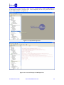
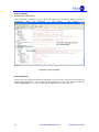
1
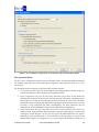
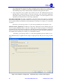
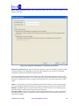
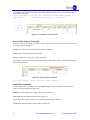
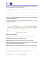
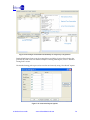
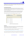
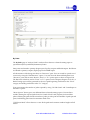
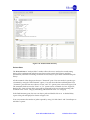
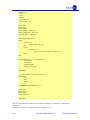
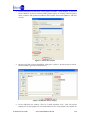
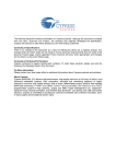
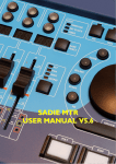
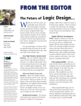
Reference point section gives details about the start point; end point and reference launch clock
and the slack of the timing path. Typical Reference Points report is as shown below:
Path Begin :
Path End :
Capture Clock :
Setup Constraint :
Path slack :
reg_0_LC_1_4_0/lcout
reg_1_LC_1_4_1/in3
reg_1_LC_1_4_1/clk
10000p
8357p
In this example, the starting point is the flop output (lcout) which is in the BLE reg_0_LC_1_4_0.
The end point is the flop input (in3 input pin of BLE which drives the flop) which is in the BLE
reg_1_LC_1_4_1. Capture Clock is the capture clock of the timing path and it is the clock pin
BLE reg_1_LC_1_4_1 . The Setup Constraint between the launch and capture clock is 10000ps.
Slack computed for the path is 8357ps.
Slack Computation:
Slack is the difference between the signal required time and signal arrival time and is computed
using the below formula:
slack = End-of-path required time - End-of-path arrival time
= (Capture Clock Arrival Time + Clock Source latency +Clock Path Delay - Setup Time) - (Launch
clock Arrival Time + Clock Source latency + Clock Path delay + Clock to Q + Data Path Delay)
Typical Slack Computation Report is as shown below:
Capture Clock Arrival Time (clk:R#2) 10000
+ Capture Clock Source Latency
0
+ Capture Clock Path Delay
1880
- Setup Time
-441
------------------------------------ --------------------------End-of-path required time (ps)
11439
Launch Clock Arrival Time (clk:R#1)
0
+ Launch Clock Source Latency
0
+ Launch Clock Path Delay
1880
+ Clock To Q
365
+ Data Path Delay
836
----------------------------------- --------------------------End-of-path arrival time (ps)
3082
So, from the timing report Slack = ( 10000+1880 -441) - (1880 + 365 +836) = 8357ps.
Detailed Clock Path and Data Path delays:
The Launch and Capture clock path delays, Data path delays shown in “Slack Computation”
section are reported in detail here.
The detailed report is shown below. The “model name” indicates the type of cell involved in the
path. For example, the cells with PRE_IO_GBUF are the IO global buffers and the cells with
LOGIC_CELL* are the LUTs. Also the report gives the details of the LUT configuration mode.
Cells used for routing are defined using I__*. The “delay” column gives the amount of time
iCEcube2 User Guide
www.SiliconBlueTech.com
92