1
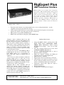
®
RigExpert Plus
User’s manual
IMPORTANT:
Read this manual carefully before
attempting to use
the RigExpert Plus device.
Table of contents
Introduction .............................................................................................. 3
Description ................................................................................................ 4
Specifications ............................................................................................ 5
Front and rear panels ............................................................................. 6
Setup instructions .................................................................................... 7
RigExpert Plus structure diagram ......................................................... 7
Driver installation guide (Windows 2000/XP/2003/Vista) ................... 8
Driver installation guide (Windows 98/ME) .......................................... 9
Driver configuration guide (Windows 2000/XP/2003/Vista) ............... 10
Driver configuration guide (Windows 98/ME) ..................................... 11
Setting up software to operate using RigExpert Plus ………............... 12
Software setup example: MixW 2 ........................................................... 13
Software setup example: DigiPan ........................................................... 14
Software setup example: MMTTY and DX4WIN ................................ 15
Software setup example: EchoLink ………………................................ 16
Appendices
A. Changing audio input or output gain, FSK baudrate and other
jumper settings ......................................................................................... 17
B. 25-pin transceiver connector pinout .................................................. 18
C. 25-pin transceiver connector description .......................................... 19
RigExpert Plus
USB Transceiver Interface
RigExpert Plus is an electronic device designed to
operate phone, CW, and digital modes using personal
computer and transceiver. Previously, a TNC or
sound card was needed for this purpose, along with
lots of cables, occupying computer sound card and
serial ports. All of this is not needed anymore.
Following up-to-date technology, USB interface is
chosen to connect RigExpert Plus to a computer. No
additional interface circuit needed for transceiver
connection.
RigExpert Plus combines:
•
•
•
•
Transceiver audio interface for operating digital modes, voice recording and playback – a totally
compatible sound card for any ham radio software.
CAT (Computer Aided Transceiver) system, which controls transceiver frequency, mode and other
functions by computer, supporting various models of transceivers.
FSK operation to get crystal-clear RTTY signal.
Built-in electronic CW keyer (using the popular WINKEY chip).
Imagine a bulk of different black boxes with
lamps and switches, a dozen of cables hanging down
the table. This gloomy picture is well-known for a
ham who prefers computer-assisted contesting or
simply wants to check out digital modes. He spends
a lot of money buying all this stuff, and then a lot of
aspirin is needed to soften his headache while
hooking it up to transceiver and computer and trying
to start up the whole system...
We have done our best to make RigExpert Plus a
breakthrough into the new era. Along with worldbeater MixW software, it is a reconsideration of
style a ham radio operator's workplace may be
organized.
For a novice, it is a first ever chance to make sure
operating digital modes is really easy. It lets
experienced DX-men and contestmen enjoy the
power of modern technology. Portable operators
will appreciate its simplicity and reliability. At last,
new horizons are open for experimenters.
RigExpert Plus is fully compatible with all
existing radio amateur software, providing easy
setup and use. Also, it includes many useful features
such as USB output for connecting computer mouse
or other USB devices, squelch input for EchoLink
software and even optical S/PDIF connectors for
modern transceivers such as IC-7800.
Internet links
RigExpert Plus features:
•
•
•
•
•
•
•
•
•
•
Along with MixW software, operates phone, CW,
PSK31, RTTY, Packet, AMTOR(FEC), MFSK,
THROB, MT63, Hellschreiber, SSTV, receives
PACTOR and fax images - all in one! No TNC
required!
Any other soundcard software may be used: tested
with DigiPan, MMTTY, EchoLink, etc.
Windows 98/ME/2000/XP/2003/Vista, as well as
Mac OS and Linux compatible.
Makes free computer soundcard and COM ports
previously used for operating digital modes.
USB connection to computer.
Single 25-pin connector for transceiver connection.
CAT interface tested with Icom, Kenwood, Yaesu,
Ten-Tec, Elecraft and JRC transceivers. The device
is able to work with any future type of transceiver.
Transformer coupled audio input and output to
minimize interference.
Shielded aluminum case.
Comprehensive documentation and support.
www.mixw.net – MixW software
www.rigexpert.com - fresh news and updates regarding RigExpert Plus
Description
RigExpert Plus is a device for operating phone, CW and digital modes using personal computer with USB port. It
provides:
•
Transceiver audio interface
Analog audio interface is a connection to transceiver audio output (external speaker connector or line
output) and transceiver audio input (microphone connector or line input). Audio interface enables
operating digital modes, recording and playing voice, as well as other useful functions (such as measuring
levels of a signal from the air) by using a computer. Input (two channels) and output volume levels are
adjusted by potentiometers on the front panel of the device.
•
Optical S/PDIF in/out
In addition to the analog audio interface, RigExpert Plus provides optical S/PDIF input and output for
modern transceivers such as IC-7800. The optical cables are widely available in HI-FI stores.
•
CAT interface for various transceiver models
CAT (Computer Aided Transceiver) system provides control of transceiver frequency, operating mode and
other functions by computer software. Normally, modern transceivers have serial (with various signal
levels) link providing CAT interface. In RigExpert Plus, CAT interface port is seen as a COM port by
computer software.
•
FSK output
FSK (Frequency Shift Keying) is a popular method of transmitting digital messages over radio primarily
used in radioteletype (RTTY) mode. Most transceivers provide FSK modulator feature to make the RTTY
signal stable and clear.
A separate COM port is assigned for the FSK output when using RigExpert Plus. The FSK baudrate and
polarity are fixed and may be reconfigured by jumpers (see the Appendix A).
•
PTT and CW output functions
Transceivers provide PTT (Push To Talk) and CW (Continuous Wave) keyer inputs to allow setting the
transmitter on or off and operating CW using external device (PTT pedal, CW bug or paddle, terminal
node controller, or personal computer).
In RigExpert Plus, PTT and CW outputs are assigned to the RTS and DTR lines of a separate COM port.
•
Squelch input
Some software, such as EchoLink, requires the interface to provide a squelch input to detect if the radio
channel is busy.
In RigExpert Plus, the squelch input is assigned to the DCD line of the COM port used for PTT and CW
outputs.
•
Built-in electronic CW keyer for single or double paddle
The keyer produces dots or dashes depending on the direction a paddle is pushed to. If using double
paddle, squeezing both paddles gives alternating dots and dashes. The speed a CW message comes out
with is set by computer software or a built-in potentiometer. A famous WINKEY micro controller was
chosen as a CW keyer in RigExpert Plus.
In RigExpert Plus, a separate COM port is assigned to the WINKEY controller.
4
Specifications
General features
•
•
•
•
•
•
Transceiver audio interface for operating digital modes, voice recording and playback
S/PDIF optical in/out
CAT (Computer Aided Transceiver) system
FSK output
Built-in electronic CW keyer (WINKEY)
USB output for connecting additional USB devices such as computer mouse.
Computer connection
•
•
•
USB (Universal Serial Bus) connector
Powered from the USB port (consuming 100 mA maximum)
No external power supply needed
Transceiver connection
•
•
Single 25-pin connector for transceiver cable
Various transceiver models supported
Audio interface
•
•
•
•
•
•
Insulated from digital nets
Maximum input/output amplitude is 1V
Input/output samplerate: 8 to 48 kHz (fixed at 8000, 16000, 32000, 44100 or 48000 Hz in S/PDIF
mode)
True 16-bit DAC/ADC used
Volume levels are adjusted by the front panel potentiometers and on-board jumpers
Standard S/PDIF optical connectors for digital interface
CAT serial port
•
•
Baudrate: 300-115200 baud
Electrical compatibility: RS-232, CI-V, TTL or inverted-TTL (Yaesu, Icom, Kenwood, Ten-Tec,
Elecraft and JRC transceivers)
PTT/CW outputs
•
•
•
PTT output: open collector and TTL-level
CW output: open collector, either software or WINKEY
Maximum current is 50 mA
FSK output
•
•
Open collector output
Baudrate is adjusted by the on-board jumpers (preset to 45.45 baud).
System requirements
•
•
Desktop or laptop Pentium computer with USB 1.1 or USB 2.0 compliant port
Windows 98/ME/2000/XP/2003/Vista or Mac OS or Linux operating system
5
Front and rear panels
1.
2.
3.
4.
5.
6.
7.
8.
9.
SPEED. CW speed pot for the WINKEY keyer. May be deactivated by software.
ON. Lights when the RigExpert Plus device is plugged in and the drivers are installed.
CW. Shows transmissions in CW mode.
PTT. Indicates when the transceiver transmits.
CAT. Monitors CAT data exchange between transceiver and computer.
FSK. Lights when RigExpert Plus is sending FSK data.
IN1. Input level, channel 1 (main receiver audio). Not active in digital audio (S/PDIF) mode.
IN2. Input level, channel 2 (sub-receiver audio). Not active in digital audio (S/PDIF) mode.
OUT. Output level (audio to the transceiver). Not active in digital audio (S/PDIF) mode.
10.
11.
12.
13.
14.
15.
IN. S/PDIF optical input.
OUT. S/PDIF optical output.
TRANSCEIVER. 25-pin transceiver connector.
PADDLE. CW paddle input.
USB OUT. USB hub output to connect USB devices such as computer mouse.
USB. Connect to the computer USB port.
6
Setup instructions
7
There are several steps needed to get ready to operate using RigExpert Plus device:
1) Insure the RigExpert Plus is unplugged from both computer and transceiver.
2) Windows users: Insert the RigExpert Plus CD into your CD-ROM drive. If the CD does
not auto-start, run SetupREP from the CD. All necessary software will be copied on your
hard drive. Windows 98/ME, as well as Mac OS and Linux users will have to install the
drivers manually from the Drivers folder on the supplied CD.
3) Plug the RigExpert Plus device into the computer’s USB port using supplied USB cable.
4) Windows 98/Me users: When the Found New Hardware Wizard appears asking for
drivers, click Browse and select \Drivers\Win98ME on the CD as a driver files location.
See the following Driver Installation Guides for details, if needed. Repeat this step until
all components of RigExpert Plus are installed.
5) Set up the serial port numbers and parameters, according to the Driver Configuration
Guides, if needed.
6) Connect RigExpert Plus to your transceiver using the supplied transceiver cable. Please
turn off your transceiver while doing this. Perform this step carefully, since incorrect
cable connection may harm the RigExpert Plus device or your transceiver.
7) Set up MixW2, DigiPan or other soundcard software (see the following examples).
8) For additional info and troubleshooting, see the RigExpert Plus website: www.rigexpert.ua.
RigExpert Plus structure diagram
Driver Installation Guide (Windows 2000/XP/2003/Vista)
Normally, the Microsoft Certified driver for these operating systems is installed when you first run the
RigExpert Plus CD. Additionally, you may find the driver files in the Drivers folder on the CD.
Continue with driver settings when you see "Your hardware is installed and ready to use" message.
8
Driver Installation Guide (Windows 98/ME)
1. After the RigExpert Plus device is plugged into
the computer USB port, a Found New window
will pop up on the computer screen.
9
5. Click Next when you see the "Windows is now
ready to install…" window.
2. A few seconds later, the Add New Hardware
Wizard will start. Click Next to continue.
3. In the next window, select Search for the best
driver for your device and click Next.
6. In the ”Windows has finished installing…” window,
click Finish.
4. Check Specify a location and click Browse to
browse for the drivers directory (normally, this is
\Drivers\Win98ME folder on your CD), then click
Next to continue.
7. Please repeat steps 2-6 when Windows finds
RigExpert Plus subdevices.
8. Now the drivers are installed and are ready to be
configured (see page 11).
Driver Configuration Guide (Windows 2000/XP/2003/Vista)
10
This guide describes Windows XP case. Other Windows versions are similar.
1. As a result of successful installation, you
will see four new serial ports in the Device
Manager (right-click My Computer on the
desktop, select Manage from the menu, select
Device Manager from the list on the left side
of the window, then open Ports (COM&LPT)
branch on the right).
4. Changing serial port numbers.
The serial port numbers are assigned automatically
during driver installation. If you need to change their
values, open Device Manager, right-click the
RigExpert Plus Serial Port (COMxx), then select
Properties from the menu. In the RigExpert Plus
Serial Port (COMxx) Properties dialog, activate Port
Settings tab, then click Advanced button.
In the newly-open Advanced Settings for COMx
dialog, select a new COM Port Number.
2. To view the RigExpert Plus serial port
assignment, please run the ListRE program
from Start – Programs – RigExpert Plus –
Show serial ports:
Click OK to apply new settings and close the Advanced
Settings for COMx dialog.
You will have to re-plug the RigExpert Plus device for
this change to take effect.
It is recommended for all four ports to uncheck the Serial
Enumerator check-box in the same window:
3. Write down the port numbers on a piece of
paper. For instance,
CAT port: COM3
PTT/CW port: COM4
WINKEY port: COM5
FSK port: COM6
These port numbers will be needed later to set
up your software.
This will eliminate a case when Windows is trying to
find a mouse or other device on this port when you plug
in the RigExpert Plus.
Driver Configuration Guide (Windows 98/ME)
1. As a result of successful installation, you
will see four new serial ports in the Device
Manager (right-click My Computer on the
desktop, select Properties from the menu, then
select Device Manager tab in the System
Properties dialog. Open Ports (COM & LPT)
branch in the device tree.)
11
4. Changing serial port numbers.
The serial port numbers are assigned automatically
during driver installation. If you need to change their
values, open Device Manager, right-click the
RigExpert Plus Serial Port (COMxx), then select
Properties from the menu. In the RigExpert Plus
Serial Port (COMxx) Properties dialog, activate Port
Settings tab, then click Advanced button.
In the newly-open Advanced Port Settings dialog,
select a new COM Port Number.
Click OK to apply new settings and close the Advanced
Port Settings dialog.
You will have to re-plug the RigExpert Plus device for
this change to take effect.
2. To view the RigExpert Plus serial port
assignment, please run the ListRE program
from Start – Programs – RigExpert Plus –
Show serial ports:
It is recommended for all four ports to uncheck the Serial
Enumerator check-box in the same window:
This will eliminate a case when Windows is trying to
find a mouse or other device on this port when you plug
in the RigExpert Plus.
3. Write down the port numbers on a piece of
paper. For instance,
CAT port: COM3
PTT/CW port: COM4
WINKEY port: COM5
FSK port: COM6
These port numbers will be needed later to set
up your software.
Setting up software to operate using RigExpert Plus
12
There are few settings that have to be done (or verified) in the software once the RigExpert Plus device is
plugged in and the drivers are installed. A combination of two or more programs may be set up to use all
functions of RigExpert Plus. Please see the software setup examples on the following pages.
CAT system
•
•
•
In the software, select the CAT port.
Set up baudrate, stop bits and parity parameters according to your transceiver manual.
RTS and DTR behavior is not significant, since RigExpert Plus does not use these lines at
CAT port.
PTT and CW outputs
•
•
•
•
In the software, select the PTT/CW port.
Set RST line to match the PTT output.
Set DTR line to match the CW output.
Baudrate, parity and other port settings are not significant.
FSK output
•
•
In the software, select the FSK port.
The FSK baudrate is fixed at 45.45 baud (which is a standard for amateur radio). To
change the baudrate, see Appendix A.
WINKEY keyer
•
•
In the software, select the WINKEY port.
Use a front panel potentiometer or software settings to adjust the CW speed.
Audio in/out
•
•
•
In the sound card software, select the USB Audio CODEC sound card. Some programs
can only work with so-called preferred sound card, which is selected via Control Panel, so
there is no such a selection there. Other programs accept numerical device IDs, so please
refer to corresponding help files.
Adjust input and output volume using front panel potentiometers. This procedure is welldescribed in various documents and publications, and is better done when the whole
system is set up.
Please notice that in S/PDIF mode, the potentiometers do not function. Also, the audio
sample rate may be fixed at 8, 16, 32 or 48 kHz by operating system.
Important:
Please remember that since CAT and PTT/CW lines are located on two different COM ports, software
should also be set to use separate ports for CAT and PTT/CW outputs.
Also, please make sure the transceiver is set up properly. For Icom transceivers, check the CI-V address
to correspond the software setting. Switch Yaesu transceivers in PKT mode if your RigExpert Plus is
plugged into the transceiver PACKET connector.
Additionally, please insure that the CW input in your transceiver is configured to use straight key.
Software setup example: MixW 2
1. Run MixW 2 and open the Sound Device
Settings dialog from Configure menu. Choose
Computer soundcard as a device type, then
select USB Audio CODEC as input and
output devices. Perform other sound device
settings, if needed.
13
3. (continued)
2a. Go to Configure – TRCVR CAT/PTT
menu to open the PTT & CAT dialog.
4. Go to Configure – Secondary PTT port – Port
settings menu. In the Serial Port dialog, select the
PTT/CW port number as a Port, then set RTS to
PTT, and DTR to CW. Uncheck Hardware flow
control. Other settings have no effect with
RigExpert Plus.
2b. Select your transceiver type and model (see
the PTT&CAT dialog above).
5. Go to Configure – FSK port – Port settings
menu. In the Serial Port dialog, select the FSK
port number as a Port. RTS and DTR settings
have no effect with RigExpert Plus.
2c. Perform additional settings according to
MixW2 manual.
•
•
To use CW output from RigExpert Plus,
uncheck the CW out via soundcard
check-box.
For using FSK mode with RigExpert
Plus, uncheck the AFSK in place of
FSK check-box.
2d. Click Details to configure the CAT serial
port.
3. In the Serial Port dialog, select your CAT
port number as a Port, then set the serial port
parameters according to the transceiver manual.
RTS and DTR settings have no effect with
RigExpert Plus.
6. Go to Configure – WinKey port – Port settings
menu. In the Serial Port dialog, select the
WINKEY port number as a Port.
Software setup example: DigiPan
1. Run DigiPan and open the Sound Card dialog
from Configure menu.
Choose Computer soundcard as a sound card type,
then select USB Audio CODEC as input and output.
2. Go to Configure – Serial port menu to open the
PTT interface dialog.
Select your PTT/CW port here, then check RTS as
PTT check-box.
14
Software setup example: MMTTY and DX4WIN
1. Perform audio in/out settings
1a. In MMTTY, go to Options –
Setup MMTTY menu.
1b. In the Setup MMTTY dialog,
select the Misc tab.
1c. Select Device ID to match the
RigExpert Plus sound card
(usually, 0 or 1).
1d. Select COM-TxD (FSK) as a
Tx Port. This setting will let
MMTTY transmit RTTY via the
FSK port.
If you prefer the soundcard mode
to be used instead of FSK, select
Sound in the Tx Port area.
2. Set up FSK port number
2a. In the Setup MMTTY dialog,
select the TX tab.
2b. Choose the Port in the PTT
area to match the RigExpert Plus
FSK Port (see the driver
configuration guide).
If using the soundcard mode (i.e.
not FSK), select PTT/CW port of
RigExpert Plus in the PTT area.
3. Set up CAT system
3a. In the DX4WIN software, go to File –
Preferences menu.
3b. In the Setup Parameters dialog, open the Radio
tab.
3c. Select your transceiver Type and parameters
according to the transceiver manual.
3d. Select COM Port to match the RigExpert Plus
CAT Port (see the driver configuration guide).
3e. Perform other settings according to the
DX4WIN manual, if needed.
15
Software setup example: EchoLink
16
This example describes the use of RigExpert Plus in Sysop mode. Please see the EchoLink manual for
additional information.
Please notice that RigExpert Plus cable diagrams do not show the connection between the transceiver’s
squelch output and pin 5 of the 25-pin connector on the back of RigExpert plus. You will need to add this
connection if you want to use the transceiver’s squelch in EchoLink.
1. Open Audio tab in the System Setup
dialog.
Choose USB audio CODEC as input and
output devices.
2. Open System Setup dialog and select
the TX Ctrl tab.
Select RTS in the PTT Activation area,
then select the Serial Port number to
match the RigExpert Plus PTT/CW port
(see the driver configuration guide).
3. Select the RX Ctrl tab. To use a
hardware carrier detect (squelch) feature,
select Serial CD in the Carrier Detect
area, then select Serial Port to match the
RigExpert Plus PTT/CW port (see the
driver configuration guide). You may
need to check the Invert Sense checkbox for some transceivers.
However, in some cases it is better to
check the VOX check-box not to use the
transceiver’s squelch.
Appendix A
17
Changing audio input or output gain, FSK baudrate and other
jumper settings
In some cases, it is necessary to change audio input or output gain to satisfy transceiver
requirements, or perform other additional settings.
Open the RigExpert Plus box with a screwdriver. Find a corresponding jumper and set it
to a new position according to the following picture.
RigExpert Plus board
1. WINKEY PTT. Close this jumper if you want the WINKEY chip control the
transceiver PTT line.
2. FSK POL. Open/close this jumper to change the output FSK signal polarity.
3. FSK PTT. Close this jumper if you want the transceiver PTT line be activated by
transmitting FSK.
4. RESET. Not used.
5. 45.45BD/75BD. Open this jumper to set the FSK baudrate to 75 baud. Close this
jumper to set the baudrate to 45.45 baud.
6. 100BD/OTHER. Close this jumper to set the FSK baudrate to 100 baud. Open this
jumper for other baudrate.
7. IN1 1:10. Channel 1 (main receiver) attenuator (1:10).
8. IN2 1:10. Channel 2 (sub receiver) attenuator (1:10).
9. OUT 1:10. Transmitter attenuator (1:10).
Factory defaults:
• WINKEY PTT and FSK PTT are ON
• Receiver and transmitter attenuators are OFF
• FSK baudrate is set to 45.45 baud
Appendix B
18
25-pin transceiver connector pinout
Pin Pin name
Description
1
14
FSK_OC
FSK open-collector output
Pullup to +5V through 4.7K resistor
2
15
3
16
4
17
5
18
6
19
DIT
DAH
VCC
PTT5V
CW_OC
PTT_OC
SQ
12V_MAX
SPK_TRCVR2
RXD_OE
7
CIV_IN
20
8
12V_TRCVR
21
9
22
10
23
11
24
12
25
13
CO_PULLUP
TXD12V
RXD12V
TXD5V
RXD5V
GND
GND
SPK_TRCVR
MIC_TRCVR
AGND_TRCVR Audio signal ground
FSK_PULLUP
CIV_OUT
CW paddle input (dit), shorten to ground
CW paddle input (dah), shorten to ground
+5V output (USB power line)
TTL-level PTT output (5V in transmit, 0V in receive mode)
Open-collector CW output
Open-collector PTT output
Squelch input, 4.7K resistor pullup to +5V
+12V output (generated by MAX232 chip)
Transceiver audio output (speaker), sub receiver
Serial input (5V levels), connect RXD5V to VCC to activate this
input
CI-V input (ICOM transceivers), pulled up to 12V_TRCVR with
4.7K resistor
Connect to VCC to power the CIV_IN input
CI-V open-collector output (ICOM transceivers), connect to
CIV_IN
Pullup to +5V through 4.7K resistor
RS-232-compatible serial output (±12V levels)
RS-232-compatible serial input (±12V levels)
Serial output (5V levels)
Serial input (5V levels)
Digital ground
Digital ground
Transceiver audio output (speaker), main receiver
Transceiver audio input (microphone)
For transceiver cable design guide and cable diagrams for most popular transceivers,
please see the www.rigexpert.ua website.
Appendix C
19
25-pin transceiver connector description
Audio in/out:
• SPK_TRCVR and SPK_TRCVR2 are connected to the transceiver speaker (or line
out) output (main or sub receiver).
• MIC_TRCVR is connected to the transceiver microphone (or line in) input.
• AGND_TRCVR is connected to the transceiver ground (connection point should be
as close to the transceiver as possible).
MixW RigExpert decouples audio in/out signals from computer signals using
transformers, which prevents interference caused by parasitic current in grounding.
FSK output:
FSK_OC is an open-collector output, sinking 50mA maximum (using BC817 NPN
transistor). Connect this pin to FSK_PULLUP to obtain the TTL-level output.
PTT and CW outputs:
PTT_OC and CW_OC are open-collector outputs, sinking 50mA maximum (using
BC817 NPN transistors). PTT5V is a TTL-level PTT output (5V in transmit, 0V in
receive mode), output current is 5mA maximum.
CW paddle inputs:
DIT and DAH are CW paddle inputs (single or double paddle for iambic keying),
pulled up to +5V with 4.7K resistors.
Serial in/out:
MixW RigExpert provides various methods of connecting serial in/out lines with
different signal levels to the virtually any model of transceiver. This only requires
shortening some pins on the MixW RigExpert transceiver connector.
• RS-232-compatible mode uses TXD12V and RXD12V lines with ±12V
signal levels, provided by MAX232 interface chip.
• CI-V mode uses CIV_IN and CIV_OUT lines (should be shortened together).
CIV_IN is internally pulled up with 4.7K resistor to 12V_TRCVR, which
should be connected to VCC.
• TTL-level (5V) mode uses TXD5V and RXD5V lines. Signal polarity is
opposite to RS-232 mode.
• Yet another TTL-level mode (signal polarity is the same as with RS-232
mode) uses CIV_OUT output (should be connected to CO_PULLUP) and
CIV_IN input (12V_TRCVR line should be connected to the VCC output). It
is better to use RXD_OE input in this mode (RXD5V should be connected to
VCC to activate this input).
Copyright © 2007 Rig Expert Ukraine Ltd.
RigExpert is a registered trademark of Rig Expert Ukraine Ltd.