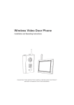
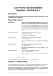
1
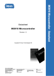
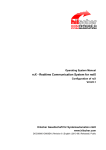
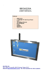
BEGV643A
USER MANUAL
LCD Embedded System,
Atmel ATmega644p MCU,
Graphic 320x240 STN LCD,
LED/white backlight,
RS232/RS422/RS485, I2C /SPI
64KB in-system programmable Flash
No Operating System required
Bolymin, Inc. www.bolymin.com.tw
[email protected]
CONTENTS
P3
P4
P5
P6
P6
P7
P7
P8
P8
P9
Precaution
Packing Contents
Chapter 1 Introduction
1-1ʳ
1-2ʳ
1-3ʳ
1-4ʳ
1-5ʳ
1-6ʳ
Features
Board Layout
Block Diagram
Mechanical Dimension
Board Specifications
Ordering Information
Chapter 2 Installation
2-1ʳ Jumpers
P10
2-1-1 Contrast adjust
2-1-2 Frame ground
2-1-3 RS-422/485 VDD/ground
2-1-4 Screw hole ground
2-2ʳ Connectors
2-2-1 Connector & Pin Definition
2-2-2 Pin vs. Function Diagram
Chapter 3 MCU Port Mapping
3-1 MCU Pin Configuration
3-2 MCU Port Mapping
3-2-1 LCD Controller
3-2-2 Touch Panel
3-2-3 RS-232/RS-422/RS-485
3-2-4 Enable Backlight
3-2-5 EEPROM/I2C
3-2-6 2-wire serial port
3-2-7 SPI
3-2-8 General I/O
Chapter 4 Software Development Tool & Utility
4-1 ATMEL ATmega644p Tool
4-1-1 Download software from AVR
studio website
4-1-2 Additional tool for C language
4-2 Execute AVR studio 4.16 on designer PC
4-3 In-system programmer AVR ISP mk II
4-4 Bolymin Free Software Utilities
4-4-1 Website links
4-4-2 Introduction of BOLYMIN
software utilities
4-4-3 Software utilities function
description
Appendix A: LCD Controller Specification
Appendix B: EEPROM Specification
Appendix C: ATMEL ATmega644p MCU Specification
BEGV643A User Manual Ver.02
-2-
P10
P11
P11
P12
P12
P12
P16
P19
P20
P21
P21
P21
P21
P21
P21
P21
P22
P22
P23
P24
P24
P32
P36
P44
P62
P62
P63
P71
Precaution
FCC
WARNING
CAUTION
This device is designed to meet the requirement in part 15 of the FCC rules. Operation is subject
to conditions ruled under FCC part 15.
BEGV643A User Manual Ver.02
-3-
Please check packing content upon receiving BEGV643A parcel, make sure that all materials
and options are packed inside parcel according to your order.
Packing Contents Check-List
Ƒ BEGV643A LCD Embedded module
Ƒ Touch panel
Ƒ Software Utility Disc
Ƒ ISP Cable (option)
Ƒ ATMEL software development tool
BEGV643A User Manual Ver.02
-4-
Chapter 1 Introduction
Abstract
This chapter is to offer you basic information regarding
BEGV643A, to help you incorporate BEGV643A into your
system.
Contents include:
1-1 Features
1-2 Board Layout
1-3 Block Diagram
1-4 Mechanical Dimension
1-5 Board Specifications
1-6 Ordering information
BEGV643A User Manual Ver.02
-5-
1-1 Features
This BEGV643A is designed based on ATmega644p microprocessor, which requires no operating system to run
on. Together with a 320x240 STN LCD and LED backlight built-in, this all-in-one LCD embedded system BEGV643A
help designer enhance a compact design with cost saving, space saving, and design phase saving.
Armed with RS232, RS422/485, I2C and SPI interface port, this BEGV643A communicates many devices and
peripherals. The BEGV643A is therefore suitable to sit as a industrial control panel for factory automation equipment,
electronics instrument, HMI (human-machine interface), office automation equipment, medical equipment, parking
system, ticketing system.. and so on.
There are five LCD colors among choices: STN/gray, STN/yellow-green, STN/blue, FSTN/Positive, and
FSTN/negative. All comes with LED/white backlight.
64KB in-system self-programmable Flash offers sufficient ROM size for designer to develop software, further to
control LCD, touch panel, and interfaces.
Designer may simply design this BEGV643A into your application as you are designing a ATMEL CPU board,
without worrying LCD module and other interfaces, since they are all on one board.
1-2 Board Layout
This layout shows the location of each important IC, connector and jumper. Please refer to chapter 2 for further
information on jumper and connector.
(Drawing 1.2)
7
1
6
1 :LCD controller
5
43 2
7 : CN2
2 :RS232
3: CN1
4 :Microprocessor
5 :RS-485/422
6 :EEPROM
BEGV643A User Manual Ver.02
-6-
1-3 Block Diagram
(Drawing 1.3)
1-4 Mechanical Dimension
(Drawing 1.4)
BEGV643A User Manual Ver.02
-7-
1-5 Board Specifications
(Table 1.5)
MCU
Memory
Display
Touch Panel(optional)
Serial Ports
High-performance, Low-power AVR® 8-bit microprocessor
ATMEL ATmega644P
64K Bytes In-System Self-Programmable Flash
2K Bytes Internal EEPROM
4K Bytes Internal SRAM
3 x 64K Bytes External EEPROM(optional)
Support 8-bit single-scan resolution 320 x 240 monochrome STN LCD, with
edge LED white backlight only
Support four-wired resistive touch panel
Support 1 x RS232 port, and 1 x RS232/RS422(isolated)/RS485(isolated)
co-shared port
Support 1 x full-duplex, three-wired synchronous data transfer SPI port
Support 1 x two-wired serial interface to 250 KHz data transfer speed
1-6 Ordering Information
(Table 1.6)
Part No.
Description
RS232-A
RS232-B
BEGV643A
Dual RS232
ϩ
ϩ
BEGV643A1
One RS232
ϩ
BEGV643A2
One RS232/One RS422
ϩ
BEGV643A3
One RS232/One RS485
ϩ
Display: FSTN/Positive LCD,LED/White Backlight(Default)
BEGV643A User Manual Ver.02
-8-
RS422
RS485
ϩ
ϩ
Chapter 2 Installation
Abstract
This chapter is to offer designer fundamental information
of BEGV643A jumpers and connectors, in order to help
designer configure correct setting and connection between
BEGV643A and system application.
Contents include:
2-1 Jumpers
2-2 Connectors
BEGV643A User Manual Ver.02
-9-
2-1 Jumpers
This section is to indicate location and function of each jumper on BEGV643A, which user can arrange according
to the needs of different application desired. Be careful when setting jumper, user maybe need tool such as
needle-nose pliers to help setting. Please note, jumpers not described here are intended to keep as factory default
setting. Please consult Bolymin before trying to change default setting.
The table listed below describes location and function of each available jumper.
Jumpers: (Table 2.1)
Label
Function
VR
LCD contrast control
RG
Frame ground
S2,S3
RS-422/RS-485 VDD/ground
JHG
Screw hole ground
Detail location and function of each jumper is illustrated below.
2-1-1 Contrast Adjust
(Drawing 2.1.1)
VR
10K ohm
N/A
Contrast adjust
Inside
Outside
BEGV643A User Manual Ver.02
default
- 10 -
2-1-2 Frame Ground
(Drawing 2.1.2)
RG
short
open
Frame ground
Connect metal frame with GND
Not connected metal frame with ground
default
2-1-3 RS-422/RS-485 VDD/Ground
(Drawing 2.1.3)
S2
short
open
S3
short
open
BEGV643A User Manual Ver.02
RS-422/RS-485 VDD/Ground
internal VDD/ground for isolated RS-422/485
External VDD/ground for isolated RS-422/485
- 11 -
default
2-1-4 Screw hole ground
(Drawing 2.1.4)
JHG
short
open
Frame ground
Connect screw hole with GND
Not connected screw hole with ground
default
2-2 Connectors
Connectors are the key link between BEGV643A and external devices. Detail locations and functions of available
connectors are tabled and illustrated below.
Connectors: (Table 2.2)
Label
Pin No.
CN1
32
Function
Connector
2-2-1 Connectors & Pin Definition
z
Connector CN1 (Drawing 2.2cn1)
BEGV643A User Manual Ver.02
- 12 -
Pin Types
I
O
Bi
U
P
z
Pin Definition: BEGV643A-Dual RS232 (Table 2.2.1a)
Pin No.
1
3
5
7
9
11
13
15
17
19
21
23
25
27
29
31
z
=Input
=Output
=Input / Output (Bi-Directional)
=User defined
=Power
Signal
GND
VDD
NC
NC
/Reset
/SS
MOSI
MISO
SCK
RX0
TX0
RX1
TX1
SDA
SCL
IOA
Pin No.
2
4
6
8
10
12
14
16
18
20
22
24
26
28
30
32
Signal
EEPSDA
EEPSCL
EEPWP
IOB
NC
NC
NC
NC
NC
NC
NC
NC
NC
NC
NC
NC
Pin Definition: BEGV643A1-One RS232 (Table 2.2.1b)
Pin No.
1
3
5
7
9
11
13
15
17
19
21
23
25
27
29
31
Signal
GND
VDD
NC
NC
/Reset
/SS
MOSI
MISO
SCK
RX0
TX0
NC
NC
SDA
SCL
IOA
Pin No.
2
4
6
8
10
12
14
16
18
20
22
24
26
28
30
32
Signal
EEPSDA
EEPSCL
EEPWP
IOB
NC
NC
NC
NC
NC
NC
NC
NC
NC
NC
NC
NC
.
BEGV643A User Manual Ver.02
- 13 -
z
Pin Definition: BEGV643A2-One RS232/One RS422 (Table 2.2.1c)
Pin No.
1
3
5
7
9
11
13
15
17
19
21
23
25
27
29
31
z
Signal
GND
VDD
NC
NC
/Reset
/SS
MOSI
MISO
SCK
RX0
TX0
NC
NC
SDA
SCL
IOA
Pin No.
2
4
6
8
10
12
14
16
18
20
22
24
26
28
30
32
Signal
EEPSDA
EEPSCL
EEPWP
IOB
NC
422RP
422RN
422TP
422TN
VDD2
VDD2
GND2
GND2
NC
NC
NC
Pin Definition: BEGV643A3-One RS232/One RS485 (Table 2.2.1d)
Pin No.
1
3
5
7
9
11
13
15
17
19
21
23
25
27
29
31
Signal
GND
VDD
NC
NC
/Reset
/SS
MOSI
MISO
SCK
RX0
TX0
NC
NC
SDA
SCL
IOA
Pin No.
2
4
6
8
10
12
14
16
18
20
22
24
26
28
30
32
Signal
EEPSDA
EEPSCL
EEPWP
IOB
NC
NC
NC
485P
485N
VDD2
VDD2
GND2
GND2
EN485
NC
NC
2-2-1-1 Power & Ground (Table 2.2.1.1)
Signal
GND
VDD
VDD2
VDD2
GND2
GND2
Type
P
P
P
P
P
P
Pin No.
1
3
20
22
24
26
BEGV643A User Manual Ver.02
Description
Logic power supply (ground)
Logic power supply (+5V)
External Power for isolated RS-422/485(+5V)
External Power for isolated RS-422/485(+5V)
External Ground for isolated RS-422/485(ground2)
External Ground for isolated RS-422/485(ground2)
- 14 -
2-2-1-2 Serial I/O (Table 2.2.1.2)
Signal
Type
Pin No.
/SS
U
11
MOSI
U
13
MISO
U
15
SCK
RX0
TX0
RX1
TX1
SDA
SCL
EEPSDA
EEPSCL
EEPWP
422RP
422RN
U
I
O
I
O
U
U
Bi
Bi
I
I
I
17
19
21
23
25
27
29
2
4
6
12
14
422TP/485P
Bi
16
422TN/485N
Bi
18
EN485
O
28
Description
SPI Chip select
MOSI is the mater data output line, when SPI on module is
configured as a master. When SPI is configured as a slave. This
pin reverse the role.
MISO is the master data input line, when SPI is configured master.
When SPI Is configured as a slave. This pin reverse the role.
SPI clock
Receiver of first RS232 with driver
Transmitter of first RS232 with driver
Receiver of second RS232 with driver
Transmitter of second RS232 with driver
Data of 2-wire serial interface, it can be programmed as IO.
Clock of 2-wire serial interface, it can be programmed as IO.
Data of 2-wire serial interface for additional EEPROM update.
Clock of 2-wire serial interface for additional EEPROM update
Write protect of additional EEPROM
no inverting receiver of RS422
inverting receiver of RS422
When it configured as RS422 it act as no inverting transmitter,
When is configured as RS 485 it acts as positive differential IO.
When it configured as RS422 it acts as inverting transmitter, When
is configured as RS 485 it acts as negative differential IO.
Enable RS-485
2-2-1-3 General I/O (Table 2.21.3)
Signal
/Reset
IOA
IOB
Type
I
U
U
Pin No.
5
31
8
BEGV643A User Manual Ver.02
Description
Auxiliary moment reset for external input
I/O port (ATmega644P portA.4)
I/O port (ATmega644P portA.7)
- 15 -
2-2-2 Pin vs. Function Diagram
2-2-2-1 Power/LCD/Backlight
Diagram of system power supply, and contrast adjustment.
VDD
+5V
GND
GND
BEGV643A
Vadj
Vout
/Reset
A
K
2-2-2-2 In-System Programming
BEGV643A offers in-system software burn-in function, which allows designer to write software into
ATmega644p via ATMEL AVR ISP MKII writer without taking ATmega644p IC off board.
Please visit following website for more information on AVR ISP MKII writer.
http://www.atmel.com/dyn/products/tools_card.asp?tool_id=3808
+5V
VDD
GND
GND
MOSI
BEGV643A
MISO
/Reset
SCK
2-2-2-3 RS-232
BEGV643A offers RS-232 port to contact PC or other RS232 device directly without ICL232.
+5V
VDD
5
GND
BEGV643A
GND
3
2
RX0
TX0
DB9
RS232 Host/Slave
BEGV643A User Manual Ver.02
- 16 -
2-2-2-4 SPI
BEGV643A offers SPI port. Designer has to define this port as SPI by software, or to use Bolymin SPI
driver (free utility).
VDD
+5V
VDD
+5V
GND
GND
GND
MOSI
BEGV643A
MOSI
M ISO
M ISO
SCK
SCK
SS
SS
Slave
Master
VDD
+5V
VDD
+5V
GND
GND
GND
MOSI
BEGV643A
MOSI
M ISO
M ISO
SCK
SCK
SS
SS
Master
Slave
2
2-2-2-5 I C/EEPROM
BEGV643A offers I2C port. Via this I2C port, designer may control 64Kbytes x 3 EEPROM in-system
and external I2C devices.
+5V
GND
VDD
GND
BEGV643A
EEPSCL
Microprocessor
EEPSDA
EEPWP
EEPROM
BEGV643A User Manual Ver.02
- 17 -
EEPROM
2-2-2-6 RS-422
BEGV643A offers 1 x RS-422(isolated) port.
VDD
+5V
GND
GND
VDD2
RS-422 isolated power
BEGV643A
RS-422 Transmitter -
RS-422 Recever +
RS-422 Transmitter +
RS-422 Recever -
RS-422 Recever -
RS-422 Transmitter +
RS-422 Recever +
RS-422 Transmitter GND2
RS-422 isolated ground
2-2-2-7 RS-485
BEGV643A offers 1 x RS-485(isolated) port.
+5V
GND
VDD
GND
BEGV643A
RS-485 isolated power
VDD2
RS-485 Transmitter/Recever -
RS-485 Transmitter/Recever +
RS-485 Transmitter/Recever +
RS-485 Transmitter/Recever -
RS-485 isolated ground
BEGV643A User Manual Ver.02
- 18 -
GND2
Chapter 3 MCU port mapping
Abstract
This chapter explains ATmega644p MCU pin
configuration and port mapping toward key
elements such as LCD, Touch Panel, RS-232,
RS-422, RS-485, LED Backlight, EEPROM/I2C,
2-wire serial port, SPI, and General I/O.
BEGV643A User Manual Ver.02
- 19 -
3-1 MCU Pin Configuration
(Drawing 3.1, ATmega644p MCU)
BEGV643A User Manual Ver.01
- 20 -
3-2 MCU Port Mapping
3-2-1 LCD Controller
(Table 3.2a)
MCU ATmega644P
PORTB.0
PORTB.1
PORTB.2
PORTB.3
PORTD.4
PORTD.5
PORTD.6
PORTD.7
PORTC.7
PORTC.5
PORTC.4
PORTC.6
3-2-2 Touch Panel
(Table 3.2b)
MCU ATmega644P
PORTA.0
PORTA.1
PORTA.2
PORTA.3
LCD Controller
DB0(LSB)
DB1
DB2
DB3
DB4
DB5
DB6
DB7(MSB)
LCD /RESET
LCD RD
LCD WR
LCD C/D
Touch Panel
X1
Y1
X2
Y2
3-2-3 RS-232/RS-422/RS-485
(Table 3.2c)
MCU ATmega644P
RS-232/422/485
PORTD.0
RX0
PORTD.1
TX0
PORTD.2
RX1
PORTD.3
TX1
(Table 3.2d)
MCU ATmega644P
PORTA.5
RS-485
Enable RS-485
3-2-4 Enable Backlight
(Table 3.2e)
MCU ATmega644P
LED backlight
PORTA.6
Enable Backlight
3-2-5 EEPROM/I2C
(Table 3.2f)
MCU ATmega644P
PORTC.2
PORTC.3
EEPROM/ I2C
EEPROM SDA
EEPROM SCL
3-2-6 2-wire serial port
(Table 3.2g)
MCU ATmega644P
2-wire serial port
PORTC.1
SDA
PORTC.0
SCL
BEGV643A User Manual Ver.02
- 21 -
3-2-7 SPI
(Table 3.2h)
MCU ATmega644P
PORTB.4
PORTB.5
PORTB.6
PORTB.7
SPI
/SS
MOSI
MISO
SCK
3-2-8 General I/O
(Table 3.2i)
MCU ATmega644P
PORTA.4
PORTA.7
General I/O
IOA
IOB
BEGV643A User Manual Ver.02
- 22 -
Chapter 4 Software Development Tool & Utility
Abstract
This chapter explains ATmega644p MCU
software development tool AVR ISP mkII writer
and Bolymin free software utilities.
BEGV643A User Manual Ver.02
- 23 -
4-1 ATMEL ATmega644p Software Development Tool
Designers may download software development tool from AVR Studio website
http://www.atmel.com/dyn/products/tools_card.asp?tool_id=2725, or from BOLYMIN utility disk.
4-1-1 Download software from AVR Studio website
step1: Download design software
Click here to download AVR Studio 4.16
Fill in necessary information and
click to download
Step2: install AVR studio on designer PC
Double click to install AVR studio4.16
BEGV643A User Manual Ver.02
- 24 -
BEGV643A User Manual Ver.02
- 25 -
Accept terms to continue
BEGV643A User Manual Ver.02
- 26 -
Select folder to install and continue
BEGV643A User Manual Ver.02
- 27 -
Select features to install and continue
BEGV643A User Manual Ver.02
- 28 -
Click install to begin installation
BEGV643A User Manual Ver.02
- 29 -
Wait for seconds for installation
BEGV643A User Manual Ver.02
- 30 -
Click finish to exit the installation
BEGV643A User Manual Ver.02
- 31 -
4-1-2 Additional tool for C language
For C language designers, additionally please download and install AVR gcc from
http://sourceforge.net/project/downloading.php?group_id=68108&filename=WinAVR-20090313install.exe&a=6759369
Double click to install WinAVR
Choose your language to install
Close other applications to continue
BEGV643A User Manual Ver.02
- 32 -
Click I agree to continue
Choose folder to continue
BEGV643A User Manual Ver.02
- 33 -
Choose components to install
Wait for seconds for installation
BEGV643A User Manual Ver.02
- 34 -
Click finish to exit installation
** AVR Studio and AVR gcc software are also available on Bolymin utility disk or Bolymin
website.
BEGV643A User Manual Ver.02
- 35 -
4-2 Execute AVR Studio 4.16 on designer PC
StartШAll programsШAtmel AVR ToolsШAVR Studio 4
Click New Project to start
Choose Atmel AVR Assembler (assembly language),
or AVR GCC(C code)
BEGV643A User Manual Ver.02
- 36 -
Choose AVR GCC here (All Bolymin utility drivers are
designed with C code), and key in Project Name and
Initial file.
Choose AVR Simulator, ATmega644P, and click
Finish to continue
BEGV643A User Manual Ver.02
- 37 -
Here you can see software design screen, yet no hurry
to start software design yet.
Choose Project ÆConfiguration Options to continue
BEGV643A User Manual Ver.02
- 38 -
Choose General and key in necessary information to
continue
Choose Include Directories, and Include File Search Path to continue
BEGV643A User Manual Ver.02
- 39 -
Choose Include as File Search Path to continue
Click Yes to continue
BEGV643A User Manual Ver.02
- 40 -
After executing AVR Studio 4.16 on PC, designer can see key information on 5 windows:
5
2
3
1
4
[1]. Project management window
BEGV643A User Manual Ver.02
- 41 -
[2]. Program editing window
BEGV643A User Manual Ver.02
- 42 -
[3]. I/O view window
[4]. Message window
[5]. Toolbars
BEGV643A User Manual Ver.02
- 43 -
4-3 In-System Programmer AVR ISP mkII
1
4
2
3
** Inside mkII box(1), designer will get DVD(2), mkII device(3), and USB cable(4).
Please be sure that all parts are packed inside.
BEGV643A User Manual Ver.02
- 44 -
Steps:
1.Get mkII connected to PC
Choose ToolsÆProgram AVRÆConnect to continue
Choose AVRISP mkIIÆUSBÆConnect to continue
BEGV643A User Manual Ver.02
- 45 -
Choose Hex file for ATmega644p flash Æ Program
Choose Hex file for ATmega644p EEPROMÆProgram
Choose ELF file for fuses and lockbitsÆ Program
BEGV643A User Manual Ver.02
- 46 -
Start software burning
Choose Auto and necessary configure
and click Start to program
BEGV643A User Manual Ver.02
- 47 -
Good job! Software burning is done!
BEGV643A User Manual Ver.02
- 48 -
Product Function Verify
On PC: StartÆAll programsÆTelecommunicationÆHyper Terminal
Please define a name and choose a icon for this connection,
and click Yes to continue.
Choose a suitable COM port, and click Yes to continue.
BEGV643A User Manual Ver.02
- 49 -
Key in COM port setting:115200/8/No/1/No,
and click Yes to continue.
BEGV643A User Manual Ver.02
- 50 -
Turn on BEGV64.A power, and designer
will see this screen.
After seeing above screen, designer can operate on PC & BEGV643A:
A). Enter number “1”: for I2C EEPROM function test (1st 2nd 3rd EEPROM)
B). Enter number “2”: for 2nd UART function test
C). Enter number “3”: for ATmega644P internal EEPROM function test
D). Enter number “4”: for 4-wire SPI Master function test
E). Enter number “5”: for 4-wire SPI Slave function test
F). Enter number “6”: to touch panel function test
G). Enter number “7”: for touch panel calibration (5 point)
H). Enter number “8”: for LCD function test
I). Enter number “9”: for backlight brightness adjustment function test
BEGV643A User Manual Ver.02
- 51 -
A). Enter number “1”: for I2C EEPROM function test (1st 2nd 3rd EEPROM)
1). Enter number “1”: for I2C EEPROM function test (1st EEPROM)
2). Enter number “2”: for I2C EEPROM function test (2nd EEPROM)
3). Enter number “3”: for I2C EEPROM function test (3rd EEPROM)
4). Enter number “0”: to return to main screen
1). Enter number “1”: to write 55 on current screen
2). Enter number “2”: to write AA on current screen
3). Enter number “3”: to write 00 on current screen
4). Enter number “4”: to write FF on current screen
5). Enter “P”: to switch to previous page
6). Enter “N”: to switch to next page
7). Enter number “0”: to return to the previous page
BEGV643A User Manual Ver.02
- 52 -
B). Enter number “2”: for 2nd UART function test
1). Enter number “1”: to send 1 byte (0x55)
2). Enter number “2”: to send 1 byte (0xAA)
3). Enter number “3”: to send 1 word (0x5555)
4). Enter number “4”: to send 1 byte (0xAAAA)
5). Enter number “0”: to return to main screen
Auto receive byte or word
BEGV643A User Manual Ver.02
- 53 -
C). Enter number “3”: for ATmega644P internal EEPROM setting
** Address 0x0000~0x001D is for touch panel calibration data
1). Enter number “1”: to write 55 on current screen
2). Enter number “2”: to write AA on current screen
3). Enter number “3”: to write 00 on current screen
4). Enter number “4”: to write FF on current screen
5). Enter “P”: to switch to previous page
6). Enter “N”: to switch to next page
7). Enter number “0”: to return to main screen
BEGV643A User Manual Ver.02
- 54 -
D). Enter number “4”: for 4-wire SPI Master function test
1). Enter number “1”: to send 1 byte (0x55)
2). Enter number “2”: to send 1 byte (0xAA)
3). Enter number “3”: to send 1 word (0x5555)
4). Enter number “4”: to send 1 byte (0xAAAA)
5). Enter number “0”: to return to main screen
BEGV643A User Manual Ver.02
- 55 -
E). Enter number “5”: for 4-wire SPI Slave function test
1). Enter number “1”: to receive 1 byte
2). Enter number “2”: to receive 1 word
3). Enter number “0”: to return to main screen
BEGV643A User Manual Ver.02
- 56 -
F). Enter number “6”: to read from touch panel
1). Using light pen to touch a point on touch panel
2). X, Y values are touch panel coordinates
3). DX, DY values are LCD coordinates (DX=0/DY=0 if touch panel is not calibrated.)
4). Enter number “0”: to return to main screen
BEGV643A User Manual Ver.02
- 57 -
G). Enter number “7”: for touch panel calibration (5 point)
1). On the LCD, designer will see displays. Please use light pen to touch center point of until it turns to
be . Such, one point is calibrated.
2). Please repeat above process to calibrate 5 points.
3). Touch panel calibration is finished.
BEGV643A User Manual Ver.02
- 58 -
H). Enter number “8”: for LCD function test
1). Enter number “1”: to LCD show full on
2). Enter number “2”: to LCD show vertical line
3). Enter number “3”: to LCD show horizontal line
4). Enter number “4”: to LCD show half
5). Enter number “5”: to LCD show cross dot
6). Enter number “6”: to LCD show character
7). Enter number “7”: to LCD show picture 1
8). Enter number “8”: to LCD show picture 2
9). Enter number “0”: to return to main screen
Full on
BEGV643A User Manual Ver.02
V line
- 59 -
H line
Half
Cross dot
Character
Picture1
Picture2
BEGV643A User Manual Ver.02
- 60 -
I). Enter number “9”: for backlight brightness adjustment function test
1). Enter number “1”: to backlight brightness + 5
2). Enter number “2”: to backlight brightness - 5
3). Enter number “0”: to return to main screen
BEGV643A User Manual Ver.02
- 61 -
4-4 Bolymin Free Software Utilities
4-4-1 Website Links
z Touch Panel Driver
www.bolymin.com.tw/embedded/utility/BEGV643A/tpdriver.zip
z
UART Driver (RS-232/485/422)
www.bolymin.com.tw/embedded/utility/BEGV643A/uartdriver.zip
z
SPI Driver
www.bolymin.com.tw/embedded/utility/BEGV643A/spidriver.zip
z
I2C Driver
www.bolymin.com.tw/embedded/utility/BEGV643A/i2cdriver.zip
z
Backlight Driver
www.bolymin.com.tw/embedded/utility/BEGV643A/backlightdriver.zip
z
LCD Driver
www.bolymin.com.tw/embedded/utility/BEGV643A/lcddriver.zip
BEGV643A User Manual Ver.02
- 62 -
4-4-2 Introduction of Bolymin software utilities
It is recommended to use Bolymin software utilities in order to speed up project development phase.
However, designer may develop your own software utilities, if you find Bolymin utilities is not convenient
to use.
On following paragraphs, we explain the way to add Bolymin software utilities into designer PC.
Note: Under AVR Studio4, ProjectĺConfiguration Options
Choose Include Directories, and Include File Search Path to continue
Note: Adding into Header files
BEGV643A User Manual Ver.02
- 63 -
Choose Include as File Search Path to continue
BEGV643A User Manual Ver.02
- 64 -
Note: For touch panel calibration, Floating-point operations is necessary, so please add libm.a and
libprintf_flt.a in WinAVR.
BEGV643A User Manual Ver.02
- 65 -
BEGV643A User Manual Ver.02
- 66 -
Note: Adding into Obj
BEGV643A User Manual Ver.02
- 67 -
BEGV643A User Manual Ver.02
- 68 -
Note: choose [Linker Options]
BEGV643A User Manual Ver.02
- 69 -
Note: key in -Wl,-u,vfprintf, and then Add
BEGV643A User Manual Ver.02
- 70 -
4-4-3 Software Utilities Function Description
4-4-3-1 UART function
Header file : uart.h
Object file : uart.o
uartInit Function: Initial UART.
void uartInit(
Syntax
uint8_t
byPort,
uint32_t uBaudrate,
uint8_t
byParity,
uint8_t
uDatabit,
uint8_t
uStopbit,
uint8_t
nTxMode
);
byPort
UART_PORT0 – 1st Uart port
Parameters
UART_PORT1 – 2nd Uart port
nBaudrat
Baud rate, ex: 9600.
byParity
Parity Check, ϖNϗ Ω None, ϖEϗ Ω EVEN, ϖOϗ - ODD.
uDatabit
data bit , 5 ~ 8.
uStopbit
data bit , 1 ~ 2.
nTxMode
Transmission Mode.
0 or FALSE Ω RS232.
1 or TRUE Ω RS485 or RS422.
None.
Return value
uartSetBaudRate Function: to set up baud rate for assigned UART port
void uartSetBaudRate(
Syntax
uint8_t
byPort,
uint32_t uBaudrate
);
byPort
UART_PORT0 – 1st Uart port
Parameters
UART_PORT1 – 2nd Uart port
nBaudrate
Baud Rate, ex: 9600.
None.
Return value
uartSendByte Function: To send 1 byte from assigned UART port
void uartSendByte(
Syntax
uint8_t
byPort,
uint8_t
txData
);
byPort
UART_PORT0 – 1st Uart port
Parameters
UART_PORT1 – 2nd Uart port
txData
byte to be sent.
None.
Return value
BEGV643A User Manual Ver.02
- 71 -
uartDisablePort Function: to stop operation of assigned Uart port
void uartDisablePort (
Syntax
uint8_t byPort
);
byPort
UART_PORT0 – 1st Uart port
Parameters
UART_PORT1 – 2nd Uart port
None.
Return value
uartSendString Function: to send 1 string from assigned UART port
void uartSendString(
Syntax
uint8_t
byPort
uint8_t* str
);
byPort
UART_PORT0 – 1st Uart port
Parameters
UART_PORT1 – 2nd Uart port
str
Index of string to be sent, ending with “0”.
None.
Return value
uartSendBuffer Function: to send buffer from assigned UART port
void uartSendBuffer(
Syntax
uint8_t
byPort,
uint8_t* buffer,
uint16_t nBytes
);
byPort
UART_PORT0 – 1st Uart port
Parameters
UART_PORT1 – 2nd Uart port
buffer
index of buffer to be sent
nBytes
bytes of buffer to be sent
None.
Return value
uartReceiveByte Function: to read 1 byte data from assigned UART port
uint8_t uartReceiveByte(
Syntax
uint8_t
byPort,
uint8_t* rxData
);
byPort
UART_PORT0 – 1st Uart port
Parameters
UART_PORT1 – 2nd Uart port
rxData
index of data to be received
Return value
TRUE Ω rxData is true data
FALSE Ω UART port no data
uartReceiveBufferIsEmpty Function: to check if there is data in assigned UART port
void uartReceiveBufferIsEmpty(
Syntax
uint8_t
byPort
);
byPort
UART_PORT0 – 1st Uart port
Parameters
UART_PORT1 – 2nd Uart port
Return value
TRUE Ω There is data on assigned UART port
FALSE Ω There is no data on assigned UART port
BEGV643A User Manual Ver.02
- 72 -
uartFlushReceiveBuffer Function: to clear receiving buffer on assigned UART port
void uartFlushReceiveBuffer(
Syntax
uint8_t
byPort
);
byPort
UART_PORT0 – 1st Uart port
Parameters
UART_PORT1 – 2nd Uart port
None.
Return value
uartEnableTx Function: to Enable or Disable UART transmitter. (When UART port is applied on RS485 or RS422 ,
transmitter must be set to Disable, and to Enable transmitter only when sending data.)
void uartEnableTx(
Syntax
uint8_t
bEnable
);
bEnable
TRUE – Enable transmitter
Parameters
FALSE – Disable transmitter.
None.
Return value
BEGV643A User Manual Ver.02
- 73 -
4-4-3-2 I2C function
Header file : i2ceeprom.h
object file : i2ceeprom.o
i2cInitial Function: Initial I2C functions. User should call this function before using I2C functions.
void i2cInitial(
Syntax
);
None.
Parameters
None.
Return value
i2cReadByte Function: to read 1 byte data from I2C
uint8_t i2cReadByte(
Syntax
uint8_t
uDevAddr,
uint16_t nAddr
);
uDevAddr
I2C device address. (address of three 24c512 on board are:
Parameters
A2hex, A4hex, A6hex.
nAddr
address to write in .
Data reading from I2C
Return value
i2cWriteByte Function: to write 1 byte data from I2C
void i2cWriteByte(
Syntax
uint8_t
uDevAddr,
uint16_t nAddr,
uint8_t
byData
);
uDevAddr
I2C device address.(address of three 24c512 on board are: A2hex,
Parameters
A4hex,A6 hex.
nAddr
address to write in .
byData
data to write in .
None.
Return value
i2cSetSpeed Function: to set baud rate for I2C
void i2cSetSpeed(
Syntax
uint16_t nSpeed,
);
Parameters
uSpeed
I2C baud rate , 0 Ω 100K, 1 Ω 250K.
None.
Return value
BEGV643A User Manual Ver.02
- 74 -
4-3-3-3 SPI function
Header file : spi.h
object file : spi.o
spiMaster Function: Initial SPI to master mode.
void spiMaster(
Syntax
uint8_t
mode
);
mode
SPI mode.
Parameters
0 – CPOL=0, CPHA=0 Sample (Rising) Setup (Falling)
1 – CPOL=0, CPHA=1 Setup (Rising) Sample (Falling)
2 – CPOL=1, CPHA=0 Sample (Falling) Setup (Rising)
3 – CPOL=1, CPHA=1 Setup (Falling) Sample (Rising)
None.
Return value
BEGV643A User Manual Ver.02
- 75 -
spiSlave Function: Initial SPI to slave mode.
void spiSlave(
Syntax
uint8_t mode,
);
mode
SPI mode.
Parameters
0 – CPOL=0, CPHA=0 Sample (Rising) Setup (Falling)
1 – CPOL=0, CPHA=1 Setup (Rising) Sample (Falling)
2 – CPOL=1, CPHA=0 Sample (Falling) Setup (Rising)
3 – CPOL=1, CPHA=1 Setup (Falling) Sample (Rising)
None.
Return value
spiSetBitrate Function: to set SPI baud rate
void spiSetBitrate(
Syntax
uint8_t
spr
);
spr
SPI baud rate. system OSC is 11.0592MHz.
Parameters
0 – OSC / 4.
1 – OSC / 16.
2 – OSC / 64.
3 – OSC / 128.
None.
Return value
spiSetDataOrder Function: to set SPI order when sending data, LSB first or MSB first.
void spiSetDataOrder(
Syntax
uint8_t order
);
order
LSB first or MSB first.
Parameters
DATA_LSB_FIRST–LSB of the data word will be transmitted first.
DATA_MSB_FIRST–MSB of the data word will be transmitted
first.(Default)
None.
Return value
spiSendByte Function: to send 1 byte data from SPI port
void spiSendByte(
Syntax
uint8_t
data
);
data
byte to be sent
Parameters
None.
Return value
spiRecvByte Function: to receive 1 byte data from SPI port
uint8_t spiRecvByte(
Syntax
);
None.
Parameters
To read 1 byte data from SPI
Return value
BEGV643A User Manual Ver.02
- 76 -
spiTransferByte Function: to send and read 1 byte data from SPI port
uint8_t spiTransferByte(
Syntax
uint8_t
data
);
data
byte to be sent
Parameters
1 byte data reading from SPI
Return value
spiTransferWord Function: to send and read 1 word from SPI port
Uint16_t spiTransferByte(
Syntax
uint16_t data
);
data
word to be sent
Parameters
1 word data reading from SPI
Return value
BEGV643A User Manual Ver.02
- 77 -
4-3-3-4 E2PROM function
E2PROM Function is built inside WinAVR, so users need only to include eeprom.h in program to call E2PROM
Function.
For exmapleΚ
#include <avr/eeprom.h>
eeprom_write_byte Function: to write 1 byte to MCU EEPROM.
void eeprom_write_byte (
Syntax
uint8_t* address,
uint8_t
value
);
address
E2PROM address to write in, range 0 ~ 0x7FF
Parameters
value
E2PROM data to write in
None.
Return value
eeprom_read_byte Function: This function read one byte from EEPROM.
uint8_t eeprom_read_byte (
Syntax
uint8_t* address
);
address
E2PROM address to read, range 0 ~ 0x7FF
Parameters
Data reading from E2PROM
Return value
eeprom_write_block Function: to write block data to EEPROM.
void eeprom_write_byte (
Syntax
void*
pointer_ram,
const void*
pointer_eeprom,
size_t
n
);
pointer_ram
index of block data to write in .
Parameters
pointer_eeprom
E2PROM address to write in, range 0 ~ 0x7FF.
n
length of E2PROM data to write in
None.
Return value
eeprom_read_block Function: to read block data from EEPROM
uint8_t eeprom_read_block (
Syntax
void*
pointer_ram,
const void*
pointer_eeprom,
size_t
n
);
pointer_ram
index of block data to read .
Parameters
pointer_eeprom
address of E2PROM to read, rnage 0 ~ 0x7FF.
n
length of E2PROM data to read
Data block read to .
Return value
BEGV643A User Manual Ver.02
- 78 -
4-3-3-5 Touch function
Header file : touch.h, a2d.h
object file : touch.o, a2d.o
touchInit Function: Initial Touch panel.
void touchInit(
Syntax
);
None.
Parameters
None.
Return value
touchGet Function: to read touch data from touch panel
uint8_t touchGet(
Syntax
int *
pX,
int *
pY
);
pX
to read X Coordinate from touch data
Parameters
pY
to read Y Coordinate from touch data
TRUE
data of pX and pY is true
Return value
FALSE
data of pX and pY is false
touchDrawCalPoint Function: to draw Calibration cross Coordinate on LCD
uint8_t touchDrawCalPoint (
Syntax
POINT* ptCal,
int
n
);
ptCal
Calibration Coordinate.
Parameters
n
Calibration Coordinate No.
None.
Return value
setCalibrationMatrix Function: to set Calibration calculation matrix
void setCalibrationMatrix(
Syntax
POINT * ptDisplay,
POINT * ptTouch,
int
n
);
ptDisplay
LCD reference Coordinate for calibration.
Parameters
ptTouch
Touch Coordinate for calibration
n
Coordinate No. for calibration
None.
Return value
getDisplayPoint Function: to change Touch Coordinate into LCD
void getDisplayPoint(
Syntax
int x,
int y,
int * pX,
int * pY
);
x
Touch X Coordinate.
Parameters
y
Touch Y Coordinate.
pX
LCD X Coordinate changed from Touch X Coordinate
pY
LCD Y Coordinate changed from Touch Y Coordinate
None.
Return value
BEGV643A User Manual Ver.02
- 79 -
4-3-3-6 LCD control function
Header file : RA8806.h
object file : RA8806.o
lcdInit Function: Initialize all parameters of LCD display. User should call this function before use functions of LCD
display.
void lcdInit (
Syntax
);
None.
Parameters
None.
Return value
lcdDisplayClr Function: Clear screen (include graphic and text layer).
lcdDisplayClr(
Syntax
);
None.
Parameters
None.
Return value
lcdSetCursorPos Function: Set the position of cursor. (UNIT=character=8*8 pixel)
void lcdSetCursorPos(
Syntax
uint8_t
x,
uint8_t
y
);
x
X coordinate of cursor
Parameters
y
Y coordinate of cursor
None.
Return value
lcdSwitchDisplay Function: ON/OFF.the display of cursor, text and graphic layer.
void lcdSwitchDisplay (
Syntax
uint8_t
display_switch
);
display_switch
Display switch flag
Parameters
DS_DISPLAY_OFF Turn off all display.
DS_TEXT_ON
Turn ON the display of text layer.
DS_GRAPHIC_ON Turn ON the display of graphic layer.
DS_CURSOR_ON Turn ON the display of cursor.
DS_BLINK_ON
Turn ON cursor blink. This flag is
available while cursor is ON.
None.
Return value
// Turn OFF all display.
Example
lcdSwitchDisplay(DS_DISPLAY_OFF);
// .Turn ON the display of text and graphic layer. Turn OFF cursor.
lcdSwitchDisplay(DS_TEXT_ON| DS_GRAPHIC_ON);
// .Turn ON the display of text layer and cursor without blink. Turn OFF graphic
layer.
lcdSwitchDisplay(DS_TEXT_ON| DS_CURSOR_ON);
// .Turn ON the display of text layer, graphic layer and cursor with blink.
lcdSwitchDisplay(DS_TEXT_ON| DS_GRAPHIC_ON |DS_CURSOR_ON|
DS_BLINK_ON);
BEGV643A User Manual Ver.02
- 80 -
lcdSetDispMode Function: Set the display mode between graphic layer and text layer.
void lcdSetDispMode (
Syntax
uint8_t
new_mode
);
New_mode
New display mode between graphic layer and text layer.
Parameters
Value : DM_OR_MODE, DM_XOR_MODE,
DM_AND_MODE
Content on Graphic layer
DM_OR_MODE
Return value
Content on Text layer
DM_XOR_MODE
DM_AND_MODE
None
lcdDraw Function: Draw input binary picture on specified area of graphic area.
void lcdDraw (
Syntax
uint8_t
x_start,
uint8_t
y_start,
uint8_t
x_end,
uint8_t
y_end,
uint8_t * pic_data,
uint8_t
mode
);
x_start
X coordinate of the top-left point of input picture. (UNIT=pixel)
Parameters
y_start
Y coordinate of the top-left point of input picture. (UNIT=pixel)
x_end
X coordinate of the bottom-right point of input picture. (UNIT=pixel)
y_end
Y coordinate of the bottom-right point of input picture. (UNIT=pixel)
pic_data
Bit map data will be drawn. Input 0 will reverse pixels of specified
area.
mode
DRAW_NORMAL:Draw the picture normally.
DRAW_REVERSE : Reverse the picture and then draw the
picture.
None.
Return value
BEGV643A User Manual Ver.02
- 81 -
lcdFillByte Function: Fill input byte value on specified area of graphic layer.
void lcdFillByte (
Syntax
uint8_t
x_start,
uint8_t
y_start,
uint8_t
x_end,
uint8_t
y_end,
uint8_t
data,
uint8_t
mode
);
x_start
X coordinate of the top-left point of specified area. (UNIT=pixel)
Parameters
y_start
Y coordinate of the top-left point of specified area. (UNIT=pixel)
x_end
X coordinate of the bottom-right point of specified area.
(UNIT=pixel)
y_end
Y coordinate of the bottom-right point of specified area.
(UNIT=pixel)
pic_data
Byte value will be filled.
Mode
DRAW_NORMAL: Fill input value normally.
DRAW_REVERSE : Reverse the input value and then fill it on the
specified area
None.
Return value
lcdPrintString Function: Print input string to specified location of text layer.
void lcdPrintString (
Syntax
uint8_t
x_start,
uint8_t
y_start,
char *
string,
uint8_t
str_count
);
x_start
X coordinate of start location that input string will be printed.
Parameters
(UNIT= character=8*8 pixel)
y_start
Y coordinate of start location that input string will be printed.
(UNIT= character=8*8 pixel)
string
string will be printed to LCD
str_count
character count of input string
None.
Return value
lcdDrawBit Function: ON/OFF the pixel on specified location of graphic layer.
void lcdDrawBit (
Syntax
uint8_t
x,
uint8_t
y,
char
bit_value
);
x
X coordinate of the location will be drawn. (UNIT=pixel)
Parameters
y
Y coordinate of the location will be drawn. (UNIT=pixel)
bit_value 1 : ON the pixel
0 : OFF the pixel
None.
Return value
BEGV643A User Manual Ver.02
- 82 -
lcdDrawRect Function: Draw rectangle by single line on graphic layer.
void lcdDrawRect (
Syntax
uint8_t
x_start,
uint8_t
y_start,
uint8_t
x_end,
uint8_t
y_end,
);
x_start
X coordinate of the top-left point of rectangle. (UNIT=pixel)
Parameters
y_start
Y coordinate of the top-left point of rectangle. (UNIT=pixel)
x_end
X coordinate of the bottom-right point of rectangle. (UNIT=pixel)
y_end
Y coordinate of the bottom-right point of rectangle. (UNIT=pixel)
None
Return value
BEGV643A User Manual Ver.02
- 83 -
4-3-3-7 Backlight PWM control function
Header file : bklight_pwm.h
object file : bklight_pwm.o
Note:Backlight PWM control used TIMER0 and INTERRUPT0
bklPWM_Init Function: Initialize all parameters of backlight PWM control function. User should call this function
before use backlight PWM control functions.
void bklPWM_Init (
Syntax
);
None.
Parameters
None.
Return value
bklSetBrightness Function: Set current brightness value of backlight.
void bklSetBrightness (
Syntax
uint8_t
brightness
);
Brightness
New brightness value
Parameters
0
– OFF backlight
1~100
– Control the brightness of backlight
None.
Return value
bklGetBrightness Function: Get current brightness value of backlight
uint8_t bklGetBrightness (
Syntax
);
None.
Parameters
Current brightness value of backlight. (0 ~ 100)
Return value
BEGV643A User Manual Ver.02
- 84 -
Appendix A: LCD Controller Specification
Appendix B: EEPROM Specification
Appendix C: ATMEL ATmega644p MCU Specification
Please download this specification from following ATMEL link:
http://www.atmel.com/dyn/resources/prod_documents/doc8011.pdf
BEGV643A User Manual Ver.02
- 85 -
<END of BEGV643A User Manual>
BEGV643A User Manual Ver.02
- 86 -