1
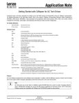
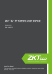
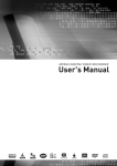
IP CAMERA OR-224i USER MANUAL MODEL: OR-224i MINIATURE BULLET IP CAMERA 2013/8/12 IMPORTANT SAFETY INSTRUCTIONS 1. 2. 3. 4. 5. 6. 7. 8. 9. Read these instructions. Keep these instructions. Heed all warnings. Follow all instructions. Do not use this device near water. Clean only with a dry cloth. Do not block any of the ventilation openings. Install in accordance with the manufacturer’s instructions. Do not install near any heat sources, such as radiators, heat registers, stoves, or any other devices that produce heat. Protect the power cord from being walked on or pinched, particularly at plugs, power outlets, or the point where the cord exits the device. 10. Only use attachments or accessories specified by the manufacturer. 11. Use only with a cart, stand, tripod, bracket, or table mount specified by the manufacturer or sold with the device. When a cart is used, use caution when moving the cart/device combination to avoid injury from the cart tipping over. 12. Unplug this device during lightning storms or when unused for long periods of time. 13. Refer to qualified service personnel for all servicing needs. Servicing is required when the device has been damaged in any way, such as when the power supply cord or plug is damaged, liquid spills or objects fall onto the device, the device is exposed to rain or moisture, the device does not operate normally, or has been dropped. 14. Caution: Danger of explosion if the battery is not properly replaced. Replace only with the same or equivalent type of battery. 15. These servicing instructions are for use by qualified service personnel only. To reduce the risk of electric shock, do not perform any servicing other than that contained in the operating instructions unless you are qualified to do so. USA & CANADA: USE CLASS 2 POWER SUPPLY ONLY OR-224i 2 Table of Contents 1. Product Features ...................................................................................................................................................................................................................................... 4 2. Installation................................................................................................................................................................................................................................................ 5 3. Accessing the Camera............................................................................................................................................................................................................................... 7 3.1 Access from a Browser ....................................................................................................................................................................................................................... 7 3.2 Accessing the IP Camera from the Internet ....................................................................................................................................................................................... 7 3.3 Adjusting the Image ........................................................................................................................................................................................................................... 8 3.4 Live View ............................................................................................................................................................................................................................................ 8 3.5 Video Stream Types ........................................................................................................................................................................................................................... 8 3.6 How to Stream H.264......................................................................................................................................................................................................................... 9 4. Setup......................................................................................................................................................................................................................................................... 9 4.1 Analog Output ................................................................................................................................................................................................................................... 9 4.2 Video................................................................................................................................................................................................................................................ 10 4.2.1 Codec................................................................................................................................................................................................................................ 10 4.2.2 Camera ............................................................................................................................................................................................................................. 12 4.3 Live .................................................................................................................................................................................................................................................. 13 4.3.1 Setup ................................................................................................................................................................................................................................ 13 4.3.2 Privacy Mask..................................................................................................................................................................................................................... 14 4.4 FTP ................................................................................................................................................................................................................................................... 15 4.4.1 Config ............................................................................................................................................................................................................................... 15 4.4.2 Event ................................................................................................................................................................................................................................ 16 4.4.3 Periodical .......................................................................................................................................................................................................................... 17 4.5 Event ................................................................................................................................................................................................................................................ 18 4.5.1 Motion.............................................................................................................................................................................................................................. 18 4.5.2 Mapping ........................................................................................................................................................................................................................... 18 4.5.3 Tamper Detection............................................................................................................................................................................................................. 19 4.6 Network ........................................................................................................................................................................................................................................... 19 4.6.1 IP Setup ............................................................................................................................................................................................................................ 19 4.6.2 Service Port ...................................................................................................................................................................................................................... 21 4.6.3 RTP ................................................................................................................................................................................................................................... 22 4.6.4 E-mail ............................................................................................................................................................................................................................... 23 4.6.5 DDNS ................................................................................................................................................................................................................................ 24 4.6.6 UPnP ................................................................................................................................................................................................................................. 24 4.7 System ............................................................................................................................................................................................................................................. 25 4.7.1 User .................................................................................................................................................................................................................................. 25 4.7.2 Date/Time ........................................................................................................................................................................................................................ 25 4.7.3 Maintenance .................................................................................................................................................................................................................... 26 4.7.4 Information ...................................................................................................................................................................................................................... 26 5. Accessory List & Dimensions .................................................................................................................................................................................................................. 27 OR-224i 3 1. Product Features This IP Camera is a high-performance H.264 network camera designed for demanding security installations. It delivers crisp, clear images that disclose every detail thanks to a top quality progressive CMOS sensor and advanced image processing. This IP Camera is supported by a wide variety of video management software solutions and provides a perfect solution for securing banks, offices, airports, and other facilities over an IP network. The optimal Power over Ethernet (IEEE 802.3af) connection to the IP Camera allows power to be delivered over the network, eliminating the need for a power outlet and reducing installation costs. Continuous power can also be guaranteed with a central Uninterruptible Power Supply (UPS). This IP Camera offers a comprehensive set of network security and management features. This includes support for portbased network control (IEEE 802.1X), which allows the camera to be connected to a network secured with this control as well as HTTPS encryption to provide a secure connection between the IP Camera and remote monitoring software. It also allows for authentication of the video source. Network video products are powerfully managed with the IP Camera Management Tool, which is provided on the Installation CD that comes with each IP Camera unit. Network Connector: This IP Camera connects to the network via a standard network cable and automatically detects the speed of the local network segment (10BaseT/100BaseTX Ethernet). This socket can also be used to power the IP Camera via Power over Ethernet (PoE). The camera automatically senses the correct power level when using a PoE (Class 2) switch, router, or injector. Reset Button: Press this button to restore the camera settings to the factory default configuration. OR-224i 4 2. Installation 1. Assemble the sun visor and connect all cables: a. Connect the IP Camera to the network using a shielded network cable. 2. Ports and Buttons: a. Adjust the IP Camera lens up/down/left/right to fit the desired position. OR-224i 5 3. Ceiling Mount: 4. Surface Mount: OR-224i 6 3. Accessing the Camera Follow the instructions in the IP Camera Installation Guide to install the camera. This IP Camera can be accessed on most standard operating systems and web browsers. For the best performance, Windows 7 and Internet Explorer 9 (32bit) is recommended. 3.1 Access from a Browser 1. Open a web browser (Internet Explorer 9 32 bit recommended). 2. Enter the IP address or host name of the IP Camera in the Location/Address field of the browser and press Enter. 3. A dialog box will pop up to Log-In. The default user name is ADMIN and the default password is 1234. 4. The IP Camera’s Live View will now be displayed on the web browser. Note: The layout of the live view page for the IP Camera may have been customized to meet specific requirements. Consequently, some of the examples and functions featured here may differ from a user’s experience. 3.2 Accessing the IP Camera from the Internet Once installed, the IP Camera is accessible on the Local Area Network (LAN). Configure the router/firewall to allow incoming data traffic to access the IP Camera from the Internet. For security reasons, this is usually done through a specific port. Please refer to the router/firewall documentation for further information and instructions. OR-224i 7 3.3 Adjusting the Image To adjust the position of the lens: 1. Open the Live View page in a web browser. Select the Setup tab and open the Installation page. Select Video Format. 2. Connect an analog monitor to the Video Out with a BNC cable. Use the image to confirm the camera is position properly. 3. Check and confirm the image is set as desired on the Live View page. 3.4 Live View 3.5 Video Stream Types H.264 Protocols and Communication Methods: o Real-time Transport Protocol (RTP): RTP is a protocol that allows programs to manage the real-time transmission of multimedia data, via unicast or multicast. o Real Time Streaming Protocol (RTSP): RTSP serves as a control protocol to negotiate the type of transport protocol to use for the stream. RTSP is used by a viewing client to start a unicast session. o User Datagram Protocol (UDP): UDP is a communications protocol that offers limited service for exchanging data in a network that uses the Internet Protocol (IP). UDP is an alternative to the Transmission Control Protocol (TCP). The advantage of UDP is that it is not required to deliver all data and may drop network packets when there is network congestion. This is suitable for live video as there is no point in re-transmitting old information that will not be displayed anyway. o Unicasting: Unicasting is communication between a single sender and a single receiver over a network. This means that the video stream goes independently to each user and each user gets a personal stream. A benefit of unicasting is if one stream fails it only affects one user. o Multicasting: Multicasting is a bandwidth-conserving technology that reduces bandwidth usage by simultaneously delivering a single stream of information to multiple network recipients. This technology is used primarily on delimited networks (intranets) as each user needs an uninterrupted data flow and should not rely on network routers. OR-224i 8 3.6 How to Stream H.264 Deciding on the combination of protocols and methods to use depends on user viewing requirements a local network properties. Setting the preferred method(s) is done on the Setup page. o RTP+RTSP: This method (actually RTP over UDP and RTSP over TCP) should be the first consideration for live video, especially when it is important to always have an up-to-date video stream, even if some of the images are lost due to network problems. This can be configured as unicast or multicast. o RTP/RTSP/Multicasting: This provides the most efficient use of bandwidth, especially when there are large numbers of clients connecting simultaneously. Note, however, that a multicast broadcast cannot pass a network router unless the router is configured to allow this. For example, it is impossible to multicast over the Internet. o RTP/RTSP/Unicasting: This should be used for video-on-demand broadcasting so that there is no video traffic on the network until a client connects and requests the stream. However, as more and more unicasts clients connect, the traffic on the network will increase and may cause congestion. Although there is a maximum of 8 unicast viewers, note that all multicast viewers combined count as 1 unicast viewer. o RTP/RTSP: This unicast method is RTP tunneled over RTSP. This could be used to exploit the fact that it is relatively simple to configure firewalls to allow RTSP traffic. 4. Setup Administrators with unrestricted access can configure the IP Camera in the web browser through the Setup tab. 4.1 Analog Output Toggle the Analog Output ON to connect via BNC output or toggle OFF and click SAVE. [Not all IP Cameras have an Analog Output] OR-224i 9 4.2 Video 4.2.1 Codec These are tools to control the camera network streams, adjust network stream video quality settings, and control the video bit rate. o Codec: H.264 and MJPEG are supported. Both streams cannot be set to MJPEG. Note that NONE is also a selection for the 2nd Stream. H.264 is a video compression standard that makes good use of bandwidth and which can provide high-quality video streams at less than 1 Mbit/s. The H.264 standard provides scope for a large range of different coding tools for use by various applications in different situations, and the IP Camera provides certain subsets of these tools. Using H.264, it is also possible to control the bit rate, which in turn allows the amount of bandwidth usage to be controlled. OR-224i 10 o Size: Video output resolution. See chart below for support resolutions: First Stream 1920x1080 1280x1024 1024x768 1280x720 704x576 704x480 640x480 640x360 352x288 352x240 320x240 o o o o o o o o o OR-224i 704x480 704x480 704x480 1280x720 704x576 704x480 640x480 640x360 352x288 352x240 320x240 640x480 640x480 640x480 704x576 640x480 640x480 320x240 320x240 - 640x360 640x360 640x360 704x480 640x360 640x360 - Second Stream 640x352 352x288 352x288 352x240 352x288 352x240 640x480 640x360 352x288 352x240 - 352x240 320x240 320x240 352x288 - 320x240 352x240 - 320x240 - Frame Rate (FPS): Choose the number of image frames per second, from 1-30fps in normal mode or 115fps when slow shutter mode is enabled. If slow shutter mode is enabled and the low light condition is met, the frame rate automatically goes down to half of the normal mode setting. GOP Size: The GOP Size can be set from 1-60 frames. Bit-rate Control: When using H.264 compression, if there is only a limited amount of bandwidth available a constant bit-rate (CBR) is recommended, although this may compromise image quality. Use a variable bit-rate (VBR) for the best possible image quality. Average Bit-rate: Can be set from 512Kbps-10Mbps. Recommended bit-rate for D1: 800Kbps-1Mbps Recommended bit-rate for 1.3M (720p): 3Mpbs-4Mbps Recommended bit-rate for 2M (1080p): 6Mbps-8Mbps MJPEG Quality: If a stream is set to use the MJPEG compression codec, the quality of the MJPEG codec can be set from 1-100, where 100 is the highest quality. Boost Quality: If Boost Quality is set to ON, the Boost FPS and Boost GOP Size can be set. If there is motion in the camera’s field, the image quality will increase using these settings. Analog Video Format: Select either NTSC or PAL video format when using the Analog Output Video Mirroring: Choose NONE for no video mirroring, HORIZONTAL for horizontal video mirroring, VERTICAL for vertical video mirroring, or FLIP for horizontal and vertical video mirroring. Bandwidth Limit: If set to ON, the maximum bandwidth can be set from 1000Kbps-30Mbps. 11 4.2.2 Camera This section allows various camera settings to be adjusted. o Exposure Control: Exposure Mode: Set to AUTO for automatic exposure control, or MANUAL to control the camera exposure manually. AGC Gain: If Exposure Mode is set to MANUAL, AGC Gain can be set from 0-36dB. For low light conditions, adjust to a higher value. e-Shutter Speed: If Exposure Mode is set to MANUAL, e-Shutter Speed can be set from ¼1/2000. MAX AGC: Max Automatic Gain Control can be set to LOW, MID, HIGH, or MAX. MAX Shutter Speed: Set the maximum shutter speed to 1/30, 1/60, 1/120, 1/180, 1/240, 1/300, or 1/360 for NTSC or 1/25, 1/50, 1/100, 1/150, 1/200, 1/250, or 1/300 for PAL. Anti-Flicker Mode: Set to 60Hz for NTSC, 50Hz for PAL, or OFF. For usage when the camera is installed in locations lit by fluorescent lighting. Slow Shutter: Can be turned on for low light conditions; can be set to x2, x4, or x8. BLC Control: Back Light Compensation control. This adjusts the exposure of scenes with strong backlight in the center-bottom of the image. When the image background is too bright or the subject is too dark, backlight compensation makes the subject appear clearer. The settings for low light behavior determine how the camera behaves at low light levels. These settings affect video image quality and how much noise is in the images. This can be set to ADAPTIVE to control on the fly, ZONE to control a certain zone, or OFF. OR-224i 12 o o Day/Night Mode: If set to AUTO, the camera will automatically switch according to current lighting conditions that persist for a set period of time. The mode can also be set to specifically DAY or NIGHT, as well as SCHEDULE. White Balance Control: WB Mode: Can be set to MANUAL, AUTO, AUTO (wideshot mode), CUSTOM (oneshot mode), or WB HOLD. This is used to make the colors in the image appear consistent, compensating for the different colors present in different light sources. The IP Camera can be set to automatically identify the light source and compensate accordingly. CUSTOM (oneshot mode) can be used to satisfy a condition that is not satisfied using other AUTO settings. MWB Mode: If white balance is set to MANUAL, the light source can be manually added, such as INDOOR (2800K), OUTDOOR (6500K), or FLUORESCENT (4000K). Image Property Control: Sharpness: Modifies the video signal sharpness. Default: 8, Range: 1-15 Brightness: Modifies the video signal brightness. Default: 15, Range: 0-30 Contrast: Modifies the video signal contrast. Default: 15, Range: 0-30 Color: Modifies the video signal color. Default: 15, Range: 0-30 4.3 Live 4.3.1 Setup This section allows for general viewer settings to be adjusted. o Viewer Setup: LiveView Protocol: Choose which protocol to use for live video. RTP Unicast (UDP), RTP Multicast (UDP), or RTP over RTSP (TCP) can be selected. Buffering Time: Buffering time can be set for a number between 0-90 times 1/30 seconds, or a range of 1-3 seconds. o Viewer OSD Setup: Resolution: Toggle OSD Resolution ON/OFF. Date/Time: Toggle OSD Date/Time ON/OFF. Event State: Toggle OSD Event State ON/OFF. OR-224i 13 4.3.2 Privacy Mask The IP Camera can support the privacy mask feature so a portion of the frame can be blocked based on personal preference of legal requirements. Select the Area and Color and click Save. Note: if the privacy mask is set, the analog output is automatically toggled off. OR-224i 14 4.4 FTP 4.4.1 Config This section is provided to set-up a FTP (File Transfer Protocol) server so the IP Camera can send recorded images to the server. o Server Configuration: FTP Server: Enable or Disable the FTP Server function for downloading recorded images. o Client Configuration: Server IP: Enter the desired FTP Server’s IP address. Port: Enter the desired FTP Server’s Port number. Default: 21, Range 1025-65535. User name: Enter the FTP Server client user name. Password: Enter the FTP Server client password Send Mode: Choose whether the send mode is Active or Passive. OR-224i 15 4.4.2 Event This page is for configuring whether or not to send images to an FTP server when an event occurs. o Event FTP Sending: FTP Sending: Choose whether to Enable or Disable this function. Directory: Input the desired file path on the FTP server for the uploaded images. File Prefix: Input the desired file name prefix (for example, alm_). FTP Send Mapping: Choose whether to upload images for either Motion or Tamper events or both. Effective Period: Choose whether to always upload images when an event occurs or during a user-defined schedule. OR-224i 16 4.4.3 Periodical This page is for configuring whether or not to periodically upload images from the camera to an FTP server. o Periodical FTP Sending: FTP Sending: Choose whether to Enable or Disable this function. Directory: Input the desired file path on the FTP server for the uploaded images. File Prefix: Input the desired file name prefix (for example, per_). Interval: Choose the desired image upload interval, from 10 seconds to 1 hour. Effective Period: Choose whether to always upload images when an event occurs or during a user-defined schedule. OR-224i 17 4.5 Event 4.5.1 Motion This page is designed to allow for different motion areas to be selected and saved. Select an area and use the mouse to click and drag the desired area, then click Save. 4.5.2 Mapping This page is designed to allow a user to select whether or not to have an e-mail notification be sent to specified users if a motion or tamper detection event occurs. The Tamper Detection menu can also be accessed from this page. OR-224i 18 4.5.3 Tamper Detection This page allows for the setup of tamper detection in order to receive alerts if the camera is being blocked or tampered with in some other way. It can be set to OFF, LOW, MID, or HIGH. 4.6 Network 4.6.1 IP Setup This page allows for current network settings to be configured, specifically the IP Camera’s IP address. The IP Camera supports IP version 4, which allows the IP address to be set automatically via DHCP (Dynamic Host Configuration Protocol) or manually via a Static IP address. DNS (Domain Name Service) configuration provides the translation of host names to IP addresses on the network. If the DHCP server can update the DNS server, it is possible to access the IP Camera by a host name which is always the same, regardless of the IP address. The 1 st DNS is the IP address of the primary DNS server on the network and the 2nd DNS is the IP address of the secondary DNS server, which is used if the primary DNS server is unavailable. By default, the IP Camera is set to get the IP address from the DHCP server and UPnP is enabled. If the network has a DHCP server and the UPnP function is enabled on a PC, it is possible to find the IP Camera in “My Network”. OR-224i 19 If a DHCP server is not available on the network, please assign the IP address as follows: o Execute Admintool.exe and click the ‘Search’ button. o Select the camera after it appears in the camera list. o Type in all of the network information. o Click the ‘Apply’ button and the settings will appear in the list. o Click the ‘Setting’ button to set network information for the IP Camera. When you double-click the camera in the list, the default web browser (Internet Explorer or compatible equivalent) will open and automatically connect to the IP Camera. OR-224i 20 4.6.2 Service Port This page is for setting the IP Camera port numbers. o Service Port: HTTP Port: Input a desired HTTP (Hyper Text Transfer Protocol port number). RTSP Port: Input a desired RTSP (Real Time Streaming Protocol port number). o Port Forwarding: Port Forwarding: Select AUTO to automatically set the connection ports of the router. Note: UPnP must be supported by the router. External IP: If Port Forwarding is successful, the external IP address for the IP Camera will be displayed. This is the address that can be used to access the IP Camera. OR-224i 21 4.6.3 RTP This page is for defining RTP (Real-Time Transport Protocol) settings for the IP Camera. RTP is used for delivering audio and video over an IP network, including multiple destinations through multicast. o RTP Port Range: Start Port: Enter the desired Start Port number. End Port: Enter the desired End Port number. o Multicast Setup: Enter the IP addresses, Video Port numbers (even values only), Audio Port numbers (even values only), and TTL values for each stream. OR-224i 22 4.6.4 E-mail This page allows users to toggle e-mail notification and specify which e-mail server is used. By default, a user can toggle notifications on and the default e-mail server will function without further setting required. o E-mail Setup: Notification: Toggle e-mail notification ON/OFF. Frequency: Select the frequency of e-mail notifications. Range: 1-60 minutes. Server: If not using the default server, input the address of the desired server. Port: If not using the default server, input the SMTP port number of the desired server. Default value: 25 Security: Toggle SSL or TLS security ON/OFF. User: If not using the default server, input the user name for accessing the e-mail server. Password: If not using the default server, input the user password for accessing the e-mail server. From: Input the name that will display before the e-mail address when receiving a notification. OR-224i 23 4.6.5 DDNS This page allows a user to enable or disable DDNS (Dynamic Domain Name System) and select an address to be used for connecting to the IP Camera. o DDNS Setup: DDNS: Toggle DDNS ON/OFF. User Set URL: Input a domain name to connect to the IP Camera (for example, http://ipcamera.dvrlink.net) 4.6.6 UPnP This page is for toggling UPnP (Universal Plug and Play) on or off. It is ON by default. OR-224i 24 4.7 System 4.7.1 User This page is for user management: adding new User IDs within a specific group and specifying the user’s password, e-mail address, and whether or not the user should receive e-mail notifications. A user may also be deleted. The Admin group allows users to change settings and view live streaming video. The User group only allows users to view live streaming video. 4.7.2 Date/Time This page configures the IP Camera date and time settings. o Date/Time Setup: Current Server Time: This displays the IP Camera’s current system time and date. Date Format: This allows the display format for the date to be changed. Time Format: This allows for the display format for the time to be changed between 12 hour and 24 hour timekeeping systems. NTP Server: If ‘Synchronize with NTP server’ is selected, input the NTP server address. Local Time: If ‘User set manually’ is selected, input the time manually or sync with a PC. Time Zone: Select the IP Camera’s time zone. DST: Toggle Daylight Savings Time ON/OFF. OR-224i 25 4.7.3 Maintenance This page is for important system maintenance for the IP Camera. o Maintenance: System Name: Input the desired name for the IP Camera. System Reboot: Reboots the IP Camera if clicked. Factory Default: Resets all IP Camera settings to original factory settings if clicked. Enable Firmware Upgrade: Must be clicked prior to performing a firmware upgrade. Firmware Updates: Browse the network directory for a firmware file and press OK to update the IP Camera firmware. 4.7.4 Information This page displays some important information about the IP Camera. OR-224i 26 Underwriters Laboratories Inc. (“UL”) has not tested the performance or reliability of the security or signaling aspects of this product. UL has only tested for fire, shock or casualty hazards as outlined in UL’s Standard(s) for Safety, UL60065. UL Certification does not cover the performance or reliability of the security or signaling aspects of this product. UL MAKES NO REPRESENTATIONS, WARRANTIES OR CERTIFICATIONS WHATSOEVER REGARDING THE PERFORMANCE OR RELIABILITY OF ANY SECURITY OR SIGNALING RELATED FUNCTIONS OF THIS PRODUCT. 5. Accessory List & Dimensions (mm) Accessory List Item IP Camera Lens Camera Stand Power Adaptor CD Printed Installation Guide Accessories OR-224i Description IP Mini Bullet Camera, 1EA Fixed lens Supplied with mounting screws PoE only User Manual CD, including product documentation, installation tools, and other software Quick Guide for installation Sun visor, 1EA Camera stand mounting screws, 3EA Screw anchor, 3EA 27 Dimensions (mm) OR-224i 28