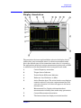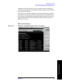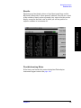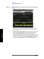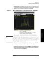
1
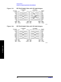
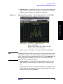
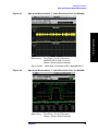
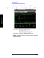
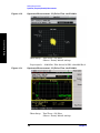
Concepts
Baseband I/Q Inputs (Option B7C) Measurement Concepts
converted signal that lie beyond the bandwidth available to the
Baseband I/Q Input circuits can not be measured (the limits are up to
5 MHz bandwidth for individual I and Q signals, and up to 10 MHz for
composite I/Q signals).
Some measurement views are appropriate for use with both RF and
baseband I/Q signals without any modification, while other views must
be altered. Some examples of measurements with identical results
views are QPSK EVM, Code Domain, and CCDF. For Spectrum
measurements, identical views include the I and Q Waveform view and
the I/Q Polar view. For Waveform measurements, identical views
include the I/Q Waveform view, the Signal Envelope view, and the I/Q
Polar view.
At RF frequencies, power measurements are conventionally displayed
on a logarithmic vertical scale in dBm units, whereas measurements of
baseband signals using Baseband I/Q inputs may be conveniently
displayed as voltage using a linear vertical scale as well as a log scale.
Spectrum Views and 0 Hz Center Frequency
Some views must be altered to account for the fundamental difference
between RF and baseband I/Q signals. For Spectrum measurements of
I/Q signals this includes using a center frequency of 0 Hz for Spectrum
views and the Spectrum Linear view. Occupied Bandwidth and Channel
Power results are also displayed using a center frequency of 0 Hz.
The center frequency of baseband I/Q Spectrum displays is 0 Hz.
Frequencies higher than 0 Hz are displayed as “positive” and those
below 0 Hz are “negative”. The “negative” portion of a multi-channel
baseband signal below 0 Hz corresponds to the portion of the signal that
would lie below the carrier center frequency when it is up converted, if
no spectral inversion occurs. As 0 Hz is a fixed center frequency, the
FREQUENCY Channel front-panel key has no active menu for baseband
I/Q Spectrum measurements.
I only and Q only Spectrum views are conventional, displayed with 0 Hz
at the left margin of the vertical axis. When up converted or multiplied,
an I only or Q only signal could ultimately lie above or below the carrier
center frequency, but in either case it will only occupy half the
bandwidth. As 0 Hz is a fixed start frequency, the FREQUENCY Channel
front panel key has no active menu keys. Use Span to change horizontal
scale. The center frequency is displayed as half the current Span.
Waveform Views for Baseband I/Q Inputs
Chapter 6
229
Concepts
For Waveform measurements, two new displays are available
exclusively for baseband I/Q input signals; the I and Q Waveform view,
which separates the individual I and Q traces, and the I/Q Polar view.
Since the horizontal axis for Waveform measurements is Time, the
FREQUENCY Channel front-panel key has no active menu for baseband
I/Q Waveform measurements. Use Span to change horizontal scale. A