1
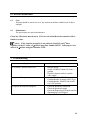
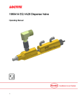
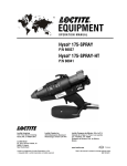
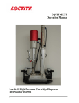
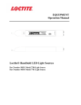
EQUIPMENT Operation Manual DISPENSE TIME AUTO ITEM NO. 1464916 PUR CONTROLLER 30ML SYRINGE MAN HEATER 2 HEATER 1 PRESSURE REGULATOR Loctite® PUR-Controller-30ml Syringe Part Number 1464916 TABLE OF CONTENTS 1. PLEASE OBSERVE THE FOLLOWING.........................................................................................................3 1.1 1.2 1.3 1.4 2. EMPHASIZED SECTIONS ...............................................................................................................................3 ITEMS SUPPLIED ..........................................................................................................................................3 ADDITIONAL ITEMS REQUIRED (NEED TO PURCHASE SEPARATELY)...........................................................3 FOR YOUR SAFETY ......................................................................................................................................3 FIELD OF APPLICATION, (INTENDED USAGE)...............................................................................................4 DESCRIPTION ....................................................................................................................................................4 2.1 2.2 THEORY OF OPERATION ..............................................................................................................................4 OPERATING ELEMENTS AND CONNECTIONS, REFERS TO FIGURE 1 ..............................................................5 3. TECHNICAL DATA...............................................................................................................................................7 3.1 4. SPECIFICATIONS ..........................................................................................................................................7 INSTALLATION .................................................................................................................................................8 4.1 4.2 UNPACKING AND INSPECTION .....................................................................................................................8 CONNECTING THE UNIT ...............................................................................................................................8 5. OPERATING THE UNIT.......................................................................................................................................9 5.1 OPERATION ..........................................................................................................................................................9 5.2 USING FOOT SWITCH / REMOTE DEVICE ..............................................................................................................9 6. CARE AND MAINTENANCE.............................................................................................................................10 6.1 6.2 CARE .........................................................................................................................................................10 MAINTENANCE ..........................................................................................................................................10 7. TROUBLESHOOTING.....................................................................................................................................10 8. DOCUMENTATION .........................................................................................................................................11 8.1 8.2 9. WIRING DIAGRAM .....................................................................................................................................11 REPLACEMENT PARTS AND ACCESSORIES .................................................................................................12 WARRANTY ......................................................................................................................................................13 2 1. 1.1 Please Observe the Following Emphasized Sections WARNING! Refers to safety regulations and required measures that protect the operator or other persons from injury or danger to life. Caution! Emphasizes what must be done or avoided so that the unit or other property is not damaged. Notice: Gives recommendations for better handling of the unit during operation or adjustment, as well as for service activities. 1.2 Items Supplied 1 PUR-Controller-30ml Syringe 1 Foot switch 1 User manual 1 Power cord 1 6mm Air Feed Line 1 4mm Air Feed Line Additional Items Required (Need to Purchase Separately) PUR-Dispense Head-30ml Syringe, Part Number 1464918 PUR-Pre Heater-30ml Syringe, Part Number 1464917 1.3 For Your Safety For safe and successful operation of the unit, read these instructions completely. If the instructions are not observed, the manufacturer can assume no responsibility. Be sure to retain this manual for future reference. WARNING! Always wear temperature resistance gloves before touch the housing of dispensing head or pre heater. WARNING! Never remove the cover of the unit without first switching the power off and unplugging the power cord. WARNING! Damage to the power cord or the housing can result in contact with live electrical parts. Check the power cord and housing before each use. If the power cord or unit is damaged, do not operate. The unit may be repaired only by a Loctite® authorized service technician. 3 1. Please Observe the Following (continued) 1.4 Field of Application, (Intended Usage) This Loctite® PUR-Contoller-30ml Syringe is designed to control the Loctite® PURDispense Head-30ml Syringe or Loctite® PUR-Pre Heater-30ml Syringe. The system can operate up to two devices. The system is designed for use with Loctite® brand PUR hotmelt adhesive products at manual or semi-automation workstations, such as in workshops, laboratories, industrial installations and production lines. It is a self-contained dispense system, that can also be can integrated with a Loctite® Benchtop Robot. 2. Description 2.1 Theory of Operation When the unit is switched on, electrical power is supplied to the temperature controller and timer. The system will reach the pre-set temperature (time varies with different preset temperatures typically within 10-15 minutes). The dispensing parameters (temperature, pressure and dispensing time) must be determined before use. The dispensing parameters depend on the properties of the adhesive product. The timed exposure cycle starts by momentarily depressing the footswitch or when an externally operated device such as Loctite® Benchtop Robot or PLC makes a relay closure across pins 1 and 9 of the nine pin footswitch connection on the rear panel. In the manual operating mode, the dispensing pressure remains open for as long as the footswitch is depressed or an external device maintains contact between pins 1 and 9. 4 2. Description (continued) 2.2 Operating Elements and Connections, refers to Figure 1 1. Pressure Gauge Displays the dispensing pressure. 2. Pressure Regulator Controls the dispensing pressure which determines adhesive flow rate. 3. Dispense Timer Controls and displays the dispense time. This controls the amount of adhesive dispensed. 4. Mode Switch Switches the system between “Manual” and “Auto” mode. 5. Heater 1 Temperature Control Controls and displays the temperature for Heater 1. 6. Heater 2 Temperature Control Controls and displays the temperature for Heater 2. 7. XS1 Foot Switch Connection Standard 9 pin “D” connector for foot switch or other external control. 8. Heater 1 Connector Connects the Heater 1 control to either dispense unit or pre-heater. 9. Heater 2 Connector Connects the Heater 2 control to either dispense unit or pre-heater. 10. Power Inlet Is used to connect the main power input. 11. Main Power Switch Controls the main power supply (ON/OFF) to the system. 12. Main Air On/Off switch Controls the main air supply (ON/OFF) to the system. 13. Air Out Connector Connects the output air to the dispense unit. 14. Air In Connector Connects the input air to the system. 5 2. Description (continued) 6 3. Technical Data 3.1 Specifications Attribute Time Range Air Input* Regulation Range of the Pressure Regulator Pressure Indication Power** Dimensions Width Depth Height Operation Temperature Storage Temperature Amperage: * Value 0 – 99.99 seconds Clean, dry air not to exceed 125 psig (8.5 bar), and filtered with a maximum of 50 micron 0 – 7 bar (0 – 100 PSI) 0 – 10 bar (0 – 145 PSI) Supply: 220V / 50 – 60 Hz, 2.0A Internal :24VDC 250 mm 160 mm 265 mm + 10°C to + 40°C (+50°F to +104°F) - 10°C to + 60°C (+14°F to +140°F) 1.5A If the required air quality is not achieved, install a Loctite® filter regulator. In the US order a 5 m filter using part number 985397. In Europe or Asia, order a 10 m filter using part number 97120. ** Note: The unit is supplied with an Asian style 240V power cord. If required cut off the plug supplied and replace with a facility compatible plug using a qualified electrician. 7 4. Installation 4.1 Unpacking and Inspection Carefully remove the system from its shipping carton and inspect it for any signs of damage. Any damage should be reported immediately to the carrier. Refer to the list of supplied parts (see page 4) and compare to the contents. Report any missing or damaged parts promptly to the Henkel local office or distributor. 4.2 Connecting the Unit - Use only the cable and hose sets supplied. Connect power cord to the main power inlet. (11). Connect air pressure supply to pneumatic connection (14). Connect the Dispense Head or Pre-Heater to the “Heater 1 Connector” or “Heater 2 Connector”. 8 5. Operating the Unit 5.1 5.2 Operation 1. Switch the main power (10) to ON position. The power switch is in the middle of the rear panel. 2. The display on the Dispense Timer (3), Heater 1 Temperature Controller (5) and Heater 2 Temperature Controller (6) will come on. 3. Set the operating mode by using the “Mode Switch” (4). Auto Mode – Engaging the footswitch starts the cycle. Dispensing will begin immediately and continue until the system times out. Manual Mode – Engaging the footswitch starts dispensing and requires holding the footswitch down until the cycle is complete. When the footswitch is released, the dispensing will end immediately. 4. Set the required temperature by adjusting the Heater 1 Temperature Control (5) and Heater 2 Temperature Controller (6). 5. Set the required dispense time by adjusting the “Dispense Timer” (3). 6. Turn the “Main Air On Switch” (12) to “ON” position. 7. Set the dispense pressure by adjusting the “Pressure Regulator” (2). 8. Dispense cycles may be initiated by using the footswitch or an externally operated device, such as a PLC controlled relay in place of the footswitch. (Refer to section 8.2). Caution: When adjusting the pressure via “Pressure Regulator”, always adjust from Low-toHigh. For example, to adjust from 4 bar to 2 bar, decrease the pressure to 0~1 bar, then increase to 2 bar. Using Foot Switch / Remote Device The Loctite® PUR-Contoller-30ml Syringe can also be actuated using a foot switch or by external devices. The foot switch connection is made up of a 9 pin D connector. Making a dry-contact relay closure across pins 1 and 9 can actuate the unit. 9 6. Care and Maintenance 6.1 Care This unit should be stored in a level, dry location at ambient condition out of direct sunlight. 6.2 Maintenance The unit requires no special maintenance. Clean, dry, filtered air must be used. If it is not, the solenoids on the controller will be fouled over time. Notice: If the required air quality is not achieved, install a Loctite® filter regulator. In the US order a 5 m filter using Part Number 985397. In Europe or Asia, order a 10 m filter using Part Number 97120. 7. Troubleshooting Symptom The “POWER” does not come “ON” Possible Corrective Action(s) 1. 2. 3. The system will not pressurize. 1. 2. 3. The dispense head does not dispense. 1. 2. 3. Plug the unit in Set the “POWER” button (10) in the “ ” ׀ position Check local power outlet to confirm 240V supply Confirm that the “AIR IN” is connected Confirm that the air supply is 80-125 psi. Confirm that the “Main Air On Switch” is in “ON” position Check the pneumatic connection Check the pneumatic supply Check the dispensing tip to make sure the dispensing tip is not clogged. 10 8. Documentation 8.1 Wiring Diagram 11 8. Documentation 8.1 Wiring Diagram 8.2 Replacement Parts and Accessories Loctite Part Number 1464918 1464917 985397 97201 1483249 1500889 1483250 1483262 1483264 1483265 1667508 1667509 Description PUR-Dispense Head-30ml Syringe PUR-Pre Heater-30ml Syringe Loctite® Air Filter, Regulator, Gauge Foot Switch Assembly Needle—All SS, 1/2” 18G Needle—All SS, 1/2” 19G Needle—All SS, 1/2” 20G Needle—All SS, 1/2” 21G Needle—All SS, 1/2” 23G Needle—All SS, 1/2” 25G SD15 Heat Controller SD15 Tip Heater 12 9. Warranty For Loctite® PUR-Controller-30ml Syringe ® Henkel expressly warrants that all products referred to in this Instruction Manual for Loctite PUR-Controller-30ml Syringe (hereafter called “Products”) shall be free from defects in materials and workmanship. Liability for Henkel shall be limited, at its option, to replacing those Products which are shown to be defective either in materials or workmanship or to credit to the purchaser the amount of the purchase price thereof (plus freight and insurance charges paid therefore by the user). The purchaser’s sole and exclusive remedy for breach of warranty shall be such replacement or credit. A claim of defect in materials or workmanship in any Products shall be allowed only when it is submitted to Henkel in writing within one month after discovery of the defect or after the time the defect should reasonably have been discovered and in any event, within twelve months after the delivery of the Products to the purchaser. No such claim shall be allowed in respect of Products which have been neglected or improperly stored, transported, handled, installed, connected, operated, used or maintained or in the event of unauthorized modification of the Products including, where products, parts or attachments for use in connection with the Products are available from Henkel, the use of products, parts or attachments which are not manufactured by Henkel. No Products shall be returned to Henkel for any reason without prior written approval from Henkel. Products shall be returned freight prepaid, in accordance with instructions from Henkel. NO WARRANTY IS EXTENDED TO ANY EQUIPMENT WHICH HAS BEEN ALTERED, MISUSED, NEGLECTED, OR DAMAGED BY ACCIDENT. EXCEPT FOR THE EXPRESS WARRANTY CONTAINED IN THIS SECTION, HENKEL MAKES NO WARRANTY OF ANY KIND WHATSOEVER, EXPRESS OR IMPLIED, WITH RESPECT TO THE PRODUCTS. ALL WARRANTIES OF MERCHANTABILITY, FITNESS FOR A PARTICULAR PURPOSE, AND OTHER WARRANTIES OF WHATEVER KIND (INCLUDING AGAINST PATENT OR TRADEMARK INFRINGEMENT) ARE HEREBY DISCLAIMED BY HENKEL AND WAIVED BY THE PURCHASER. THIS SECTION SETS FORTH EXCLUSIVELY ALL OF LIABILITY FOR HENKEL TO THE PURCHASER IN CONTRACT, IN TORT OR OTHERWISE IN THE EVENT OF DEFECTIVE PRODUCTS. WITHOUT LIMITATION OF THE FOREGOING, TO THE FULLEST EXTENT POSSIBLE UNDER APPLICABLE LAWS, HENKEL EXPRESSLY DISCLAIMS ANY LIABILITY WHATSOEVER FOR ANY DAMAGES INCURRED DIRECTLY OR INDIRECTLY IN CONNECTION WITH THE SALE OR USE OF, OR OTHERWISE IN CONNECTION WITH, THE PRODUCTS, INCLUDING, WITHOUT LIMITATION, LOSS OF PROFITS AND SPECIAL, INDIRECT OR CONSEQUENTIAL DAMAGES, WHETHER CAUSED BY NEGLIGENCE FROM HENKEL OR OTHERWISE. Henkel Corporation One Henkel Way Rocky Hill, CT 06067-3910 USA Henkel Canada Corporation 2515 Meadowpine Boulevard Mississauga, Ontario L5N 6C3 Canada Henkel Corporation Automotive/ Metals H.Q. 32100 Stephenson Hwy, Madison Heights 48071 USA Henkel Capital, S.A. de C.V. Calzada de la Viga s/n Fracc. Los Laureles Loc. Tulpetlac, C.P. 55090 Ecatepac de Morelos, MEXICO Henkel Singapore Pte Ltd 401, Commonwealth Drive #03-01/02 Haw Par Technocentre SINGAPORE 149598 Henkel (China) Company Ltd. No. 928 Zhang Heng Road, Zhangjiang, Hi-Tech Park, Pudong, Shanghai, China 201203 Henkel Loctite Korea 8F, Mapo Tower, 418, Mapo-dong, Mapo-gu, Seoul, 121-734, KOREA Henkel Japan Ltd. 27-7 Shin Isogo-cho, Isogo-ku Yokohama, 235-0017 JAPAN www.equipment.loctite.com Loctite is a trademark of Henkel Corporation, U.S.A. © Copyright 2006. Henkel Corporation Teflon is a registered trademark of E.I. DuPont de Nemours Co., Inc. All rights reserved. Data in this operation manual is subject to change without notice. Manual P/N: 8902416 Rev H, Date: 12/03/2013 13