1
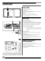
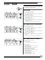
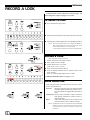
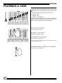
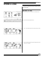
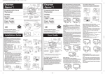
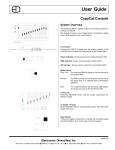
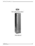
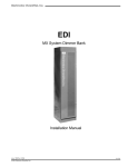
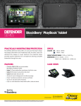
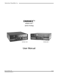
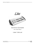
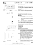
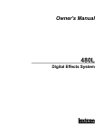
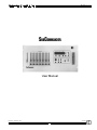
SubCommander SubCommander User Manual 070-0600 Revision 8, September 1998 ©1998 Electronics Diversified, Inc. 1 SubCommander INTRODUCTION This User Manual is supplied with your system. Copies of this guide may be obtained from Electronics Diversified, Inc. for a nominal charge. It is recommended that you copy those portions of this manual applicable to your present use in the installation, maintenance or repair and preserve the original in a safe place. © 1998, by Electronics Diversified, Inc. All rights reserved. No part of this manual may be reproduced by any means, graphic, electronic, or mechanical, including photocopying, recording, taping, or information storage and retrieval systems, without the express written permission of Electronics Diversified, Inc., except in connection with installation, operation, repair and maintenance of Electronics Diversified, Inc. systems. TABLE OF CONTENTS The SubCommander is designed to operate as a DMX copy machine. Any combination of lighting levels which pass through the unit can be copied by the SubCommander. The copy process can be performed locally or by remote control. When the lighting levels from a DMX console are live, SubCommander can learn the levels and store them for recall. SubCommander looks are organized and controlled by the twelve playback handles located on the front panel. Each playback can store levels independent of the other. Playbacks operate on a highest takes precedence basis. SubCommander offers twelve pages of twelve playbacks for memory storage. All recorded memory is protected by a ten-year lithium battery. The page window, which indicates the active page number, can be changed at any time. SubCommander allows more than one look from one page to be active at any time. The LEDs under the playback handles alert the operator to the current status of any playback. This manual is designed to familiarize you with the operation and capacities of the SubCommander unit. Each step in the table of contents targets a specific feature. Note carefully the steps required to access each of the features. Record a Look To Select a Page . . . . . . . . . . . . . . . . . . . . . . . . . . . . . . . . . . . 6 Record a Look . . . . . . . . . . . . . . . . . . . . . . . . . . . . . . . . . . . . . 6 Mode Selection. . . . . . . . . . . . . . . . . . . . . . . . . . . . . . . . . . . . 6 Overview Front Panel Controls . . . . . . . . . . . . . . . . . . . . . . . . . . . . . . . . 3 Front Panel Playbacks . . . . . . . . . . . . . . . . . . . . . . . . . . . . . . 3 Back Panel . . . . . . . . . . . . . . . . . . . . . . . . . . . . . . . . . . . . . . . 4 Disk Drive . . . . . . . . . . . . . . . . . . . . . . . . . . . . . . . . . . . . . . . . 4 Format a Disk from SubCommander . . . . . . . . . . . . . . . . . . . 4 Clock/ Timer Set Clock . . . . . . . . . . . . . . . . . . . . . . . . . . . . . . . . . . . . . . . . 5 Set Timer Count-Down Mode . . . . . . . . . . . . . . . . . . . . . . . . 5 Set Timer Count-Up Mode . . . . . . . . . . . . . . . . . . . . . . . . . . . 5 Edit a Look View a Preset . . . . . . . . . . . . . . . . . . . . . . . . . . . . . . . . . . . . . 7 Edit a Level . . . . . . . . . . . . . . . . . . . . . . . . . . . . . . . . . . . . . . . 7 Playback a Look Playbacks . . . . . . . . . . . . . . . . . . . . . . . . . . . . . . . . . . . . . . . . 8 Store a Look Record to Disk . . . . . . . . . . . . . . . . . . . . . . . . . . . . . . . . . . . . 9 Recall a Look Load Memory from disk . . . . . . . . . . . . . . . . . . . . . . . . . . . . 10 Clear Memory . . . . . . . . . . . . . . . . . . . . . . . . . . . . . . . . . . . . 10 Options Remote Record From EnAct Console . . . . . . . . . . . . . . . . . . . . . . . . . . 11 From Plus Console . . . . . . . . . . . . . . . . . . . . . . . . . . . 12 Events Clock . . . . . . . . . . . . . . . . . . . . . . . . . . . . . . . . . . . . . 13 Remote Access 10-Button Remote . . . . . . . . . . . . . . . . . . . . . . . . . . . . 14 Remote Page Selection . . . . . . . . . . . . . . . . . . . . . . . . 14 DMX Window . . . . . . . . . . . . . . . . . . . . . . . . . . . . . . . . . . . . 14 Service Information . . . . . . . . . . . . . . . . . . . . . . . . . . . . . . . . . . . . . . 15 Registration Information . . . . . . . . . . . . . . . . . . . . . . . . . . . . . . . . . . . . . . . 17 2 SubCommander OVERVIEW FRONT PANEL CONTROLS 2 3 4 5 7 6 8 1. 3.5 Disk Drive DISPLAY KEYS: 2. HOURS/PLAYBACK Access Button 3. MIN/DIMMER Button 4. SEC/LEVEL Button 5. RUN/STOP/UP Button: (Raise key) 6. RESET/DOWN Button: (Lower key) CLOCK/EVENT CONTROLS: 7. Clock Timer=Time 8. Event Clock 9. Power Key Switch: ON OFF RECORD ACCESS 10. Page/Event Button & Display 9 1 13 FUNCTION KEYS: (Access to Playback pages Display; 98-Event T/C Memory Display; dual 8-segment LED display) 11. RECORD Button: Access to 'Write' Disk 12. EDIT Button: Access Edit Memories 13. DISK Button: Access Disk Drive 14. REMOTE Button: Remote access to recall station 15. MODE Switch:Access to Output Features PILE ON: "Highest Takes Precedence" to Primary Output PASS-THRU: No SubCommander output SOLO: SubCommander only output 16. Indicator LED's: POWER: Power ON condition TIME CLOCK:Active TC program in operation DMX: DMX Input detected OVERTEMP: Signal from Dimmer Bank heat sensors 14 16 10 1 11 12 15 FRONT PANEL PLAYBACKS 2 3 1. GRAND MASTER SLIDER: 2. PLAYBACK FADERS: 12 - 60mm potentiometers with output scales. 3. STATUS LED’S: Green LED: Indicates active memory on active page. Red LED: Indicates Playback active on another page. Amber LED: Indicates active Edit mode. 4. PLAYBACK BUTTONS: Forces assigned levels to Full. Access to playback edits when used with Edit key. Access to page numbers when used with Page key. Access to remote recalls when used with Remote key. 4 3 SubCommander OVERVIEW BACK PANEL 3 ●●●●●●●●●●●●●● 1. STAGE PANEL UNIT: 19" Rack-mount configuration. 2. DMX OUTPUT: 14-pin connector labeled for input and out control. All control terminations occur at this position. 3. POWER: Input power connection from power supply. Connect only Low Voltage power to Stage Panel Unit. (See system drawings) 2 1 Disk Drive DISK DRIVE 3.5" IBM format, 1.44MB Disks must be formatted before use. 1. Insert the diskette as illustrated. Do not force it into the drive. If the diskette will not insert easily, it is not correctly oriented. 2. To eject the diskette, push the small button on the disk drive. 3. Ensure that diskettes are handled in the following manner: Do not expose to high temperatures Do not store near magnetic fields Indicator Light NOTE: Never eject a diskette while the disk drive indicator light is on. This could result in loss of data or incomplete loading of a show. Wait until the indicator light goes off before ejecting. Eject Button WRITE PROTECTION: 1. Orient the diskette so that the round metal circle is pointed toward you. 3.5" Disk Write-protect Tab 2. With the metal flap on top, the write-protect tab is located in the lower right-hand corner. If this tab is closed, the diskette is not Write Protected. If the tab is open, the diskette is Write Protected, and no new data can be written in. FORMAT A DISK FROM SUBCOMMANDER 23 F 1. Turn Key Switch to Record Access position. Ë Press and hold Edit & Remote buttons simultaneously while pressing the #12 Bump button. 3. Page LED will show FD (Format Disk). 4. The Hours LED screen will show TR and count to 80 in the Seconds screen. Ë Ë Ë 4 SubCommander CLOCK / TIMER Turn Keyswitch to Record Access position. ON position does not allow access to changes in Memory. SET CLOCK ➊ 06 30 22 ➋ ➍ Ê Position switch to Clock mode Ë Press and hold Hours button. 3. Press (RAISE) or (LOWER) button for desired number. Release the HOURS button. Í Press and hold Minutes button. 5. Press (RAISE) or (LOWER) button for desired number. Release the MIN button. ➏ Ï Press and hold Seconds button. 7. Press (RAISE) or (LOWER) button for desired number. Release the SEC button. 8. The Clock will display current time when keyed 'ON'. SET TIMER COUNT-DOWN MODE Ê Position switch to Timer mode Ë Press and hold Hours button. 02 3 0 00 ➋ ➍ 3. Press (RAISE) or (LOWER) button for desired hour number. Release the HOURS button. ➊ Í Press and hold Minutes button. 5. Press (RAISE) or (LOWER) button for desired minutes number. Release the MIN button. ➏ Ï Press and hold Seconds button. 7. Press number. (RAISE) or (LOWER) button for desired seconds 8. When set, Timer will count down from established time. SET TIMER COUNT-UP MODE 00 01 00 ➋ Ê Position switch to Timer mode Ë Press RUN button. ➊ Clock will automatically start to count up. TO STOP TIMER: Press RUN/STOP button. Timer will stop count. TO RESTART TIMER: Press RUN/STOP button. Timer will restart. TO RESET TIMER TO 00 TIME: Press Reset button. Timer will restart to zero. TO VIEW THE CLOCK: Position the Mode switch to CLOCK. TO VIEW THE TIMER: Position the Mode switch to TIMER 5 SubCommander RECORD A LOOK SubCommander memory is fixed at 12 'Looks' per page. The unit is designed to support 12 pages of 12 'Looks'. TO SELECT A PAGE 00 Ê Press and hold the Page button. ➊ Ë Select the Bump/Playback number which represents the page. ➋ Ì Selected page number will appear in the Page display window. 02 NOTE: Any active playback fader up will change from GREEN to RED, indicating fader look is from a previous page. LED's not illuminated indicates no memory stored. The Active page is always announced on the Page Display. ➌ RECORD A 'LOOK' ➌ (Source generated by another device) 1. Position Keyswitch to RECORD ACCESS. Ë Select page for Preset storage. Ì Position Mode switch to PILE ON. 02 ➋ (DMX Indicator light will illuminate.) Í Press and hold the RECORD button. Î Press the BUMP/PLAYBACK button under the fader for the preset number. 6. Green LED will immediately illuminate to confirm. ➍ For REMOTE RECORD options, see page 11, 12. ➎ MODE SELECTION 1. Mode Selection Switch can be positioned at any time; in three distinct operational levels. PILE ON: Merges stored memories from SubCommander with DMX signals generated by another source. PILE ON operates on a 'highest takes precedence' basis. PASS-THRU: Restricts SubCommander outputs and allows DMX signals generated by another source to address dimmers. SOLO: Limits other DMX signals to zero and allows only SubCommander 'looks' to address dimmers. NOTE: If Mode Selection switch is changed without key in RECORD ACCESS, Time Clock colons will flash until switch is returned to previous position. Selection is possible only when keypositioned 6 SubCommander EDIT A LOOK TO VIEW A PRESET 1. Position Key Switch to RECORD ACCESS. Ë Select page. Ì Press and hold the Edit button. Í Select the Playback bump button preset number to be edited.* 02 *If memory space is empty, dash bars will appear in all display windows. ➌ ➋ ➍ TO VIEW A RECORDED DIMMER WITH AN ASSIGNED LEVEL 01 Ê Press and hold the MIN/DIMMER button. Ë Use the arrow to select the Dimmer number. The level ➋ assigned will automatically appear in the Level window. ➊ TO EDIT THE LEVEL 1. Select the Dimmer for the level edit. Ë Press and hold the SEC/LEVEL button. Ì Press the arrow to increase the intensity level, or press the ➌ 4. 5. ➋ arrow to decrease the intensity level. When the level adjustment is complete: Press and hold the MIN/DIMMER button Press the or arrow to access the next dimmer. NOTE: During a view or edit session, the LED above the selected preset number will flash amber. When the session is complete, the LED will restore to a green condition. TO END THE SESSION Press the EDIT button. The displays will restore to the Clock or Timer condition. 7 SubCommander PLAYBACK A LOOK Playbacks operate as 'PILE-ON' memories controlled by the Grand Master. Any number of playbacks may be up at the same time. The LED's below the Playbacks identify the look as: ACTIVE -- Green PAGED -- Red IN EDIT -- Amber (Blinking) Paged looks were brought up when a previous page was displayed. When the playback is returned to the '0' position, the current 'Look' will automatically load on the playback. TO ACTIVATE A PLAYBACK: Push the playback handle UP. TO FADE OUT A PLAYBACK: Pull the playback handle DOWN. TO CHANGE THE ACTIVE PAGE: Press and hold the Page button. Press the bump button under the number of the Playback to access the same page number. TO PROPORTIONALLY CONTROL ALL PLAYBACKS: Raise or lower the Grand Master. 8 SubCommander STORE A LOOK Make sure a formatted disk is installed. Label disk, and check Write-Protect switch. RECORD TO DISK Ê Press and hold the Record & Disk buttons simultaneoously. 02 ➊ ➊ Ë Press the first Bump/Playback button. ➋ 3. Wait -- LED on disk drive will show ST during record procedure. S 1 4. SubCommander will signal through the Display Window when the process is complete. ➍ G -- - - G 9 SubCommander RECALL A LOOK Make sure a formatted disk is installed. Label disk, and check Write-Protect switch. LOAD MEMORY FROM DISK Ê Press and hold the Disk button. 01 ➊ Ë Press bump button #1. ➋ 3. Wait -- LED on disk drive will show LD during load procedure. L G 1 4. SubCommander will signal through the Display Window when the process is complete. -- -- G CLEAR MEMORY 1. Press and hold Edit & Remote buttons simultaeously while pressing the #10 Bump button. 2. Display window will show CLR. 10 SubCommander OPTIONS REMOTE RECORD THE ENACT TO SUBCOMMANDER: SETUP Version 2./0 Grandmaster FL The EnAct has the capacity to automatically download any stage output to SubCommander's page and playbacks through the DMX signal transmission. 9:01:00 MAIN MENU 1> System 2> Cues 3> Submaster 4> Patch 5> Front Panel 6> Save to Disk Functions 7> Load from Disk Functions 8> Print Functions 9> Clear Functions 10> Time Functions 11> Peripherals / Utilities 1. To copy stage output to SubCommander: A. Set levels on channels manually. or Insert or merge Group, Submaster, Cue on stage. or Manually activate playback. B. Move Fader, Playback, or Grandmaster to output position. C. Press Enter: key to activate Main Menu screen. Press (Peripherals/ Utilities Menu) Press (Selects page to remote record to SubCommander) SETUP Version 2./0 Grandmaster FL 9:01:00 Press # (1 thru 12), PERIPHERALS/UTILITIES 1> Return to main menu 2> Designers remote . . . . . . . . . . . . . . . . . . . . Yes 3> Hand held remote . . . . . . . . . . . . . . . . . . . . Yes 4> Midi input . . . . . . . . . . . . . . . . . . . . . . . . . . No 5> Smpte input . . . . . . . . . . . . . . . . . . . . . . . . No 6> Subcommander page . . . . . . . . . . . . . . . . . . 1 7> SubCommander playack . . . . . . . . . . . . . . . . 2 8> Remote record to SubCommander 9> Format disk 10> Screen 2 0:CUE 1:PLYBK 2:TRK 3:STG 4:EDIT . . . . .0 11> Screen 3 0:CUE 1:PLYBK 2:TRK 3:STG 4:EDIT . . . . .0 12> Screen 4 0:CUE 1:PLYBK 2:TRK 3:STG 4:EDIT . . . . .0 Cursor down to item #7, press Press playback #, then to assign. Cursor down to item #8, press "Are you sure?" will appear in the screen's command line: Press ENTER again to complete the record. Enter: NOTE: Playback number will automatically advance to protect against record over. Are you sure? 11 SubCommander OPTIONS REMOTE RECORD THE PLUS TO SUBCOMMANDER: 1. To copy stage output to SubCommander: Set levels on channels manually; or load preset to fader; or Load preset on submaster; or Manually move submaster. 2. Move Fader or Submaster to output position. 3. On the Plus keypad: Press [ SETUP ] 1. 3. 5. 7. 9. 11. 13. Test Channels Test Dimmers Show Version Unity Patch Auto Follow Wrapping Check Disk Midi Address 2. 4. 6. 8. 10. 12. 14. 4. Press Item #14; (REMOTE STORE). Display window shows SET-UP. Change Channel Count Change Dimmer Count Clear Memory Modulus Patch +Independent Not Assigned GM Format Disk Remote Store 5. Press Page # (#1 thru #12) UP (#1 thu #12). Stores in SubCommander memory on page and playback. 6. Press 7. Press SE to display set-up screen. 01 12 The remote record is complete. to restore Stage screen. SubCommander OPTIONS EVENTS CLOCK TO SET EVENTS CLOCK: Ê Move Clock switch to TC position. Ë Position switch in the Time Clock ON mode. Ì To set Event number, press and hold the Page button. Ê Use the (RAISE) or 1 - 99 events available. Ë (LOWER) button to select number. 4. Set Time for Event (see Set Clock functions, pg 6). 5. Press the Edit button. 6. Press and hold the Page button. 7. Use the (RAISE) or (LOWER) button to access page number of stored presets. 8. Press and hold the Playback button. 9. Use the number. Ì (RAISE) or (LOWER) button to select preset 10. Press and hold the Minutes button. 11. Use the minutes. (RAISE ) or (LOWER) button to select fade time 12. Press and hold the Seconds button. 13. Use the seconds. (RAISE) or (LOWER) button to select fade time 14. Press the Edit button to select level for preset. 15. Use the set level. (RAISE ) or (LOWER) button to select the pre- 16. Press the EDIT button to complete the edit. 17. Position Clock/Timer switch to Clock. 18. SubCommander Events Clock is operating in background. Programs set in Events Clock are controlled by the Time Clock ON/OFF switch. 13 SubCommander OPTIONS REMOTE ACCESS SubCommander memories are available for recall from remote locations. If remote recall stations are installed, they default to the first page. 10-BUTTON REMOTE The 10-Button Remote supports one full page of SubCommander playbacks. The top 3 buttons on each side represent the first 6 playbacks. The illuminated button indicates the active playbacks selected. The MORE key simply switches from the first six playbacks to the second six. When the MORE key is illuminated, the second six pages are available for selection. Only one remote memory can be active at a single time. Selecting another playback from a different station forces SubCommander to crossfade between the playbacks at a 5second rate The and keys allow Master adjustments to any playback. REMOTE PAGE SELECTION FROM STAGE PANEL: Press and hold Remote button. Press and hold Page button. Press Bump button number. DMX WINDOW DMX Window Packet size: 0 SIMPLE TO OPERATE: The DMX WINDOW offers a simple, low cost alternative to distributed video signals in any Performance Facility. Unlike video signals based on a specific console, the DMX WINDOW displays "the whole stage picture" at any time. The DMX WINDOW is designed to graphically display any dimmer and level information sent from any source generator. The DMX WINDOW will constantly update and refresh the screen, allowing the viewer to monitor the dimmer outputs of one or more control devices addressing the system at any one time. SIMPLE TO CONNECT: The DMX WINDOW is as simple as a DMX in-line connection. Connect the standard DMX cable from any DMX control console into the labeled DMX-IN connector on the chassis. Connect the cable to the dimmer bank into the labeled DMX-OUT connector on the chassis. Connect the video monitor to the VIDEO-OUT connector on the chassis. Plug the power cord for the monitor into the 120VAC receptacle. Plug the chassis into a 120 VAC source. Switch On the chassis and turn On the monitor. OPERATION: Any dimmer addressed by the control console will be displayed in the window. Use the page key to access numbers not displayed in the 140-dimmer field indicated on the CRT. Dimmers 1 - 140 Updates per second: 0 01 02 03 04 05 06 07 08 09 10 11 12 13 14 15 16 17 18 19 20 21 22 23 24 25 26 27 28 29 30 31 32 33 34 35 36 37 38 39 40 41 42 43 44 45 46 47 48 49 50 51 52 53 54 55 56 57 58 59 60 61 62 63 64 65 66 67 68 69 70 71 72 73 74 75 76 77 78 79 80 81 82 83 84 85 86 87 88 89 90 91 92 93 94 95 96 97 98 99 100 101 102 103 104 105 106 107 108 109 110 111 112 113 114 115 116 117 118 119 120 121 122 123 124 125 126 127 128 129 130 131 132 133 134 135 136 137 138 139 140 DMX Windows is available in monochromatic or VGA color output. 14 SubCommander SERVICE EDI offers a 24 hour Service / Support Network. For technical questions about this product or operational assistance, ask for Customer Service at: . . . . . . . . . . . . 1-800-547-2690 You may communicate by FAX: . . . . . . . . . . . . . . . . . . . . . . . . . . . . . . . . . . . . . . . . . . . . . . . . . . . . . . . . . . . . . . . . 1-503-629-9877 After Hours Emergency contact: . . . . . . . . . . . . . . . . . . . . . . . . . . . . . . . . . . . . . . . . . . . . . . . . . . . . . . . . . . . . . . . 1-503-645-5533 Ask for Emergency Assistance. Internet: . . . . . . . . . . . . . . . . . . . . . . . . . . . . . . . . . . . . . . . . . . . . . . . . . . . . . . . . . . . . . . . . . . . . . . . . . . . . . . . www.edionline.com Internet E-Mail: . . . . . . . . . . . . . . . . . . . . . . . . . . . . . . . . . . . . . . . . . . . . . . . . . . . . . . . . . . . . . . . . . . . . . . [email protected] If your SubCommander needs repair, call 503-645-5533 for a Return Materials Authorization number, and a shipping address will be furnished. This auxilllary control is a product of: 1675 N.W. Cornelius Pass Road, Hillsboro, Oregon 97124 USA 15 SubCommander NOTES 16 SubCommander Attention SubCommander owners! Please return this registration card immediately. Your prompt attention to this matter will ensure your receiving updated technical information for this product as it becomes available. Please complete all information. Look for acknowledgment of your registration within 6-8 weeks. Name: _______________________________________________________ Title: ________________________________________________________ Facility and/or Company: ________________________________________ _____________________________________________________________ Street Address: _______________________________________________ _____________________________________________________________ City: ____________________________ State: ______ Zip: __________ Phone: ______________________________________________________ ! CUT ALONG DOTTED LINE Fax: _________________________________________________________ E-mail: ______________________________________________________ Web site: ____________________________________________________ Mail to: EDI User Manual Registration 1675 NW Cornelius Pass Road Hillsboro, Oregon 97124 or FAX to: (503) 629-9877 Revision 0, May 1998 17