1
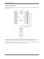
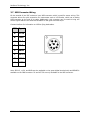
NexSens Technology, Inc.
1328 Parkway Court • Beavercreek • OH • 45432
Phone: (937) 426-2703 • Fax: (937) 426-1125 • E-Mail: [email protected]
Visit us on the web at http://www.NexSens.com
iSIC-OEM – Intelligent Sensor Interface for Control
Operations Manual and Reference Guide
Revision 07.06.21
NexSens Technology, Inc.
iSIC User’s Manual
NexSens Technology, Inc.
TABLE OF CONTENTS
1
Principles of Operation ............................................................................................. 5
1.1
1.2
2
iSIC-OEM Components ...................................................................................... 5
iSIC Specifications............................................................................................... 8
iSIC-OEM Telemetry ................................................................................................. 10
2.1
iSIC-OEM - Direct to PC .................................................................................. 10
2.1.1
2.1.2
Typical Site...............................................................................................................................10
Communication......................................................................................................................11
iSIC - RS485 ...................................................................................................................... 13
2.1.3
2.2
iSIC - Modbus ....................................................................................................... 14
2.2.1
2.2.2
3
RS232 ........................................................................................................................ 18
SDI-12....................................................................................................................... 19
Analog mV Sensors ........................................................................................... 21
Analog 4-20 mA .................................................................................................. 23
Rain Gauge Input ............................................................................................... 25
Digital Input\Output........................................................................................ 26
MS8 Connector Wiring..................................................................................... 27
iChart Setup and Operation ................................................................................. 28
4.1
4.2
4.3
Setup Device Wizard ........................................................................................ 28
Changing iSIC Configuration and Setup............................................... 34
Scheduling.............................................................................................................. 35
4.3.1
4.3.2
4.4
4.5
4.6
Automatic Interrogation Schedule ............................................................................35
Sync iSIC Real Time Clock to PC Schedule ............................................................36
Alerts and Alarms .............................................................................................. 37
4.4.1
4.4.2
4.4.3
5
Communication......................................................................................................................14
Troubleshooting a Direct Connect Data Logger .................................................17
Sensor Wiring............................................................................................................... 18
3.1
3.2
3.3
3.4
3.5
3.6
3.7
4
Communication......................................................................................................................13
iChart Alarms ..........................................................................................................................38
iSIC Control Alarms.............................................................................................................43
Monitoring Critical Projects ...........................................................................................45
iChart Software and iSIC Firmware Updates .................................... 46
What an IT Administrator Needs to Know.......................................... 47
Field Deployment ....................................................................................................... 48
5.1
5.2
5.3
5.4
Mounting the iSIC-OEM .................................................................................. 48
Grounding Protection ...................................................................................... 49
Powering the iSIC .............................................................................................. 50
Stainless Steel Enclosures............................................................................ 51
iSIC User’s Manual
1
NexSens Technology, Inc.
6
Maintenance .................................................................................................................. 52
Advanced iSIC Diagnostics........................................................................................... 53
6.1 What COM port am I using?......................................................................... 53
Cannot communicate to an iSIC: .......................................................................... 55
6.2 Sensor Diagnostic Tools................................................................................. 58
Appendix ................................................................................................................................. 62
Appendix
Appendix
Appendix
Appendix
A: Safety........................................................................................................ 62
B: Warranty and Service ..................................................................... 63
C: Options and Accessories ............................................................... 64
D: Connecting Specific Sensors....................................................... 65
iSIC User’s Manual
2
NexSens Technology, Inc.
About NexSens Technology, Inc.
NexSens Technology, Inc. was started in the 1990s with a mission to advance the capabilities
and simplify the development of environmental monitoring systems. Our main focus is on the
creation of easy-to-use computer software and powerful communications technology to provide
advanced remote data acquisition and data logging systems.
iChart is an easy-to-learn, easy-to-use Windows-based software program designed to interface
with the industry’s most popular environmental monitoring sensors and systems. A large multivendor instrument library makes setup quick and easy. iChart automates much of the tedious
programming, data collection and manual data processing common with other environmental
data collection systems.
The NexSens iSIC (Intelligent Sensor Interface and Control) is a state-of-the-art line of data
loggers that simplify the collection of real-time data from environmental sensors and monitoring
instruments. The iSIC data logger supports multi-vendor sensor connections and is designed for
environmental data monitoring with NexSens communication equipment and software.
Remote data acquisition systems have been developed specifically for unattended monitoring
applications. NexSens telemetry systems provide real-time access and 2-way communication to
remote environmental monitoring systems via direct-connect, landline phone, radio, and cellular
telemetry.
How to Use This Manual
This manual is designed to provide you with detailed instructions for interfacing specific sensors
to the NexSens iSIC data logger.
Important: Before attempting to interface a sensor with a NexSens data logging system, it is
important that you have thoroughly read the operation manual(s) provided with your NexSens
system and environmental monitoring sensor(s).
This manual provides you with all the information needed to interface your sensor with the iSIC
data logger. For advanced system and sensor reference material:
Review the material in the iSIC operations manual:
o
http://www.nexsens.com/support/manuals.htm
Review the sensor manufacturer’s operations manual. This information should have been
provided with the purchase of the sensor. This material can also typically be found at the
instrument manufacturer’s website.
If you are still having difficulty, email your technical support question to:
[email protected]
iSIC User’s Manual
3
NexSens Technology, Inc.
Unpacking and Inspection
Before you setup your iSIC Data logger, take a few minutes to insure that all equipment is
present and un-damaged. Data loggers ship in custom foam packaging to help avoid damage
from shipments. It is recommended to keep this packaging if you plan on shipping the data
logger again. Among the items included with the iSIC are:
NEMA 4x enclosure with integral data logger
RS232 interface & power cable
Five desiccant bags
Resistor pack (includes four 56Ω resistors)
Two feed-through gland fittings
Some versions of the iSIC-OEM may come with the additional optional accessory:
Stainless Steel Enclosure
Be sure to check for all signs of visible damage due to shipping – cracks in the enclosure,
damage to the enclosure’s seal. If any damage is present, please call a NexSens customer
service representative.
iSIC User’s Manual
4
NexSens Technology, Inc.
1 Principles of Operation
1.1 iSIC-OEM Components
External:
The enclosure that houses a NexSens iSIC PCB, and wiring is a durable NEMA 4X enclosure. It
measures 8.5” x 6.5” x 5.5” (inches) and is constructed of heavy-duty high-impact, corrosion
resistant thermoplastic material. The enclosure is UV stabilized for outdoor use and complies with
UL-94 minimum V-2 requirements.
This enclosure is certified for both indoor and outdoor use. Falling dirt, rain, sleet, snow,
windblown dust, splashing water, hose-directed water, and corrosion will not damage the
enclosure. In addition, the box will be undamaged by the formation of ice on the enclosure. A
number of connectors are located externally on the iSIC-OEM enclosure:
▫
Expansion Plugs - Can be replaced with conduit or half-inch gland fitting for
connecting sensors to the internal data terminal pins. Two gland fittings are
supplied with each iSIC to allow cables to enter the inside of the iSIC enclosure.
▫
▫
MS8 – Allows for the connection of RS232 Port 0 or RS485.
▫
Ground Lug – Connector for copper ground wire from A38 ground kit.
MS4 Dual power and Communication Connector – Connector for iSIC
communication. This connector allows for RS232 direct connect and power with just
one cable into the iSIC-OEMs, etc.
iSIC User’s Manual
5
NexSens Technology, Inc.
Internal:
A number of connectors are located internally on the iSIC enclosure:
▫
Fuse – A fuses is located at the top right edge inside the iSIC enclosure. This fuse
connects to the external power source. The iSIC-OEM comes preinstalled with a 3A
time delay or slow blow fuse, max rating for 250VAC.
▫
Digital and Analog Phoenix connectors - Two 16-pin un-pluggable terminal strip
connectors are located inside the enclosure. Power and sensors will be connected to
these terminals. The connector on the left is for connecting digital and smart
sensors. The connector on the right is for connecting analog sensors. Descriptions
for the pins on both connectors are given below:
iSIC User’s Manual
6
NexSens Technology, Inc.
Digital and Analog Connectors:
2 3
5
1-SDI-12
16-Tip
2-SW.A
15-Ring
iSIC DB9
Female
Connector
3-BAT
4-GND
14-Ex.5V
13-AD0
11-AGND
7-GND
10-AD2
8-P2.Rx
9-P2.Tx
Analog
12-AD1
6-P1.Tx
Digital
5-P1.Rx
9-AD3
8-AGND
10-GND
7-AD4
11-P3.Rx
6-AD5
12-P3.Tx
5-AGND
13-GND
4-AD6
14-DIO0
3-AD7
15-DIO1
2-AGND
16-Rain
1-DA0
Digital Connector
Analog Connector
SDI-12: Connection for SDI-12 sensors.
SW.A: 12V, 200 mA power switch.
BAT: Pass-through battery power pin
(fused)
GND: Ground (digital)
P1.Rx: RS232 Receive Pin (Port 1) - Input
P1.Tx: RS232 Transfer Pin (Port 1) - Output
P2.Rx: RS232 Receive Pin (Port 2) - Input
P2.Tx: RS232 Transfer Pin (Port 2) - Output
P3.Rx: RS232 Receive Pin (Port 3) - Input
P3.Tx: RS232 Transfer Pin (Port 3) - Output
DIO0: General purpose Digital I/O.
DIO1: General purpose Digital I/O.
Rain: Tipping bucket rain gauge input
Tip:
Ring:
Ex.5V:
AD0 – AD7:
AGND:
Telephone wire connection pin
Telephone wire connection pin
5V Excitation voltage
Analog Inputs
Analog ground
DA0:
Digital to Analog output
iSIC User’s Manual
7
NexSens Technology, Inc.
1.2 iSIC Specifications
Analog Inputs
Standard: 4 differential or 8 Single-Ended
Optional: 4 differential or 8 Single-Ended additional
0-2.5V auto range. 12-bit resolution.
Analog Outputs
Two 12-bit channels
0-5V or 0-2.5V Programmable
Pulse Counters
One tipping bucket counter, max rate: 12Hz
Digital I/O Ports
Two standard generic I/O ports, two additional optional
SDI-12 Interface
One SDI-12 port for up to 10 SDI-12 sensors, v1.3 compatible
RS232 Interface
Four RS232 ports, two additional optional
RS485 Interface
One RS485 port
Can be configured as master or slave
Modbus Interface
RS232 or RS485
Can be configured as master or slave
Internal Memory
512k Flash memory – over 124,000 data points minimum
Power Requirements
Voltage: 10.7V to 16VDC
Typical Current Draw
3 mA sleep, 8 mA processing, 36 mA analog measurement
Temperature Range
-20°C to +60°C
iSIC User’s Manual
8
NexSens Technology, Inc.
Dimensions:
(NEMA 4X Enclosure): 8.4” x 6.4” x 4.9” (inches)
iSIC User’s Manual
9
NexSens Technology, Inc.
2 iSIC-OEM Telemetry
2.1 iSIC-OEM - Direct to PC
2.1.1 Typical Site
The NexSens iSIC-OEM supports direct connect communication between a remote monitoring
site and a computer base station. It is the most desirable system for a monitoring site that is
under 250ft away from the monitoring station, and where a cable can easily run between the
two.
Shown below is an example site:
The above system consists of the following components:
1.
2.
3.
4.
PC running iChart Software
A60-A64-OEM RS232 Direct Connect Cable
iSIC Data logger
A22 20-Watt Solar Panel connected to external battery
iSIC User’s Manual
10
NexSens Technology, Inc.
2.1.2 Communication
Before your PC can begin to receive real-time data from the iSIC, a RS232 Direct Connect Cable
must be connected into the iSIC enclosure.
Important: Always remove power from all NexSens communications devices when wiring to the
iSIC.
NexSens supplies a variety of permanent RS232 Direct Connect Cable lengths ranging from 25 ft
to 250 ft. For stand alone applications, without continuous real time connections, you may use
an A72 RS232 Direct Connect cable to communicate with the iSIC. This cable simply requires
connecting the iSIC DB9 connector to the PC COM port. This cable is supplied with every iSIC in
a poly tube bag along with desiccant, sealcon fittings, and a 4-20mA resistor pack.
For real time connection to your data logger, A60-A64-OEM Cables will need to be used. The
MS4 connector is located on the outside of your iSIC-OEM enclosure, simply connect the MS4
connector on the A60-A64-OEM DB9 to MS4 cable to the MS4 connector located on the iSIC and
the DB9 connector to an open COM port on a PC running iChart software.
iSIC User’s Manual
11
NexSens Technology, Inc.
MS4 Pin Description:
Color
MS4
DB9
Signal
Black
A
5
GND
Red
B
NC
Power
Yellow
C
2
iSIC Rx
Orange
D
3
iSIC Tx
DA
CB
iSIC User’s Manual
12
NexSens Technology, Inc.
2.2 iSIC - RS485
2.2.1 Communication
The NexSens iSIC-OEM supports RS485 communication, at either 9600 or 19200 baud, between
the data logger and a RS485 network. RS485 connections are available on the MS8 connector,
located on the outside of iSIC enclosures.
MS8 Connector:
RS485 networks can connect to an RS485 iSIC using an RS485 MS8-Flying lead cable.
When using RS485 mode, the iSIC address is used as the RS485 address. This address can be
setup and changed in the Advanced | iSIC | iSIC tab.
Communication to an RS485 iSIC can either be with a PC running iChart software using an
RS485 to RS232 converter, or be configured for Modbus protocol and used by a PLC or other
Modbus device.
iSIC User’s Manual
13
NexSens Technology, Inc.
2.3 iSIC - Modbus
2.3.1 Communication
The NexSens iSIC-OEM supports Modbus RTU communications over RS232 or RS485.
Implementation:
• Modbus RTU over RS232 or RS485.
• Baud rates: 19200 or 9600 at No Parity, 8 Data Bits, and 1 Stop Bit
• Modbus address: same as the iSIC address.
• Input registers 0 to n-1 correspond to parameters 0 to n-1 where n = the number
of parameters that the iSIC logs.
• Each input register holds the corresponding parameter reading scaled up 100. So for
example 74.52 degrees Fahrenheit would be stored as 7452.
Supported commands:
0x04
- read input register
Perform sensor read and return result in the requested registers.
Depending on sensors installed, this could take anywhere between 1 seconds to
several minutes.
0x06
- write register
Register 0x1000: set the iSIC startup mode:
LOBYTE = mode
1 = iSICMODE_LOG
2 = iSICMODE_POLL
3 = iSICMODE_POLLNLOG (not supported)
4 = iSICMODE_MODBUS_RTU
8 = iSICMODE_MODBUS_ASCII (not supported)
HIBYTE = 1 if the iSIC is to be reset after successfully set the startup mode.
This will soft reset the iSIC and go to the new mode. If the flag is 0,
the iSIC will stay in Modbus mode after successfully set the iSIC
startup mode. The user will need to cycle the power or wait until the
hourly reset to enter the new mode.
Error Codes:
0x01 =
0x02 =
0x03 =
0x04 =
0x05 =
0x06 =
MODBUS_ECODE_ILLEGAL_FUNCTION
MODBUS_ECODE_ILLEGAL_ADDRESS
MODBUS_ECODE_ILLEGAL_DATAVAL
MODBUS_ECODE_SLAVEDEV_FAIL
MODBUS_ECODE_ACK
MODBUS_ECODE_SLAVEDEV_BUSY
To setup the iSIC data logger for Modbus protocol, first setup the iSIC with the specific sensors
connected to it. For information on how to setup and wire these sensors you can read one of the
NexSens Interface Manuals found here: http://www.nexsens.com/support/manuals.htm
It is recommended that a 1 minute log interval is selected when setting up a data logger for
Modbus telemetry for testing purposes. This allows you to make sure you are receiving good
iSIC User’s Manual
14
NexSens Technology, Inc.
readings from the sensors after a few minutes in the lab. After receiving a few readings, the data
logger should be set to a 0 minute log interval.
After you have setup the data logger and have received a few good readings, go to the
Advanced | iSIC | iSIC menu.
The iSIC Setup dialog box will appear.
Check to make sure the COM Port field has selected the correct COM port the direct connect
cable is attached to. If it is not, click on the Change COM Port, Baud… button and select the
correct COM port from the menu. By default the iSIC Data logger will use 9600 baud, N81 (No
parity, 8 data bits, 1 stop bit). The address can be left as 0 and the connection should be set to
Direct connect.
Next, click Connect and go to the general tab.
iChart will read the current configuration settings of the iSIC. This will take a few seconds. After
the above screen goes away, if there are all ??? on the bottom of the general tab, hit Close.
Then simply reset power to the iSIC (by removing power and then reapplying it) and try again.
iSIC User’s Manual
15
NexSens Technology, Inc.
Also double check to make sure you have selected the right COM port and communication
settings.
After iChart has successfully read the status information, it will be displayed on the bottom of the
screen
.
Here you will be able to setup the iSIC for your Modbus network. Place a check mark near the
Communication options you would like to change. For example, place a check mark next to
Change iSIC mode, then select Modbus and click Apply.
If needed for your network, you can also change the baud rate using Change baud and the
parity, data bits, and stop bits using Change frame. If you will be using this iSIC on a RS485
Modbus network, be sure to also change the iSIC protocol to 485. Follow the wiring instructions
in the iSIC 485 Telemetry section. When you have finished making changes hit Apply and
reset power to the iSIC. Note: changes to communication settings will not take affect until after
power has been reset.
iSIC User’s Manual
16
NexSens Technology, Inc.
2.3.2 Troubleshooting a Direct Connect Data Logger
If at some point an iSIC no longer responds to iChart software there a few steps to follow to
troubleshoot the connection:
1. First, make sure the COM port entered into iChart is correct (See the section “What COM
Port am I using?” later on in this manual).
a. If when you try to communicate to a data logger, and iChart fails immediately, it
is unable to open the COM port.
b. Also make sure the connection to the data logger is secure. Check both cable
ends, the one connected to the PC and the one connected to the iSIC.
2. Next cycle the iSIC by removing the two fuses inside of the iSIC enclosure for a few
seconds and then reconnecting them. After cycling the power wait a few moments for the
iSIC to restart and iChart to connect to it. You will see a green flashing light in the LED
hole.
iSIC User’s Manual
17
NexSens Technology, Inc.
3 Sensor Wiring
3.1 RS232
In addition to the single RS232 port located externally on the iSIC via the MS8 connector, three
RS232 ports are available on the internal Digital terminal strip. Ports 1, 2, and 3 are available
for use. To connect your RS232 sensor to the iSIC, open the enclosure, unscrew the correct pins
on the terminal strip, and attach the wires from your sensors cable to the connector. A diagram
showing the proper wiring for Port 1 is shown below:
Simply connect the Rx pin of the sensor to the Tx pin on the iSIC and the Tx pin of the sensor to
the Rx pin on the iSIC.
RS232 Ports 2 and 3 can be accessed through the same terminal strip. Port 2 uses pins 7
through 9, Port 3 uses pins 10 through 12. RS232 Sensors requiring a 12V power supply to
operate should connect the wire for power to pin 3, BAT, on the terminal strip.
iSIC User’s Manual
18
NexSens Technology, Inc.
3.2 SDI-12
Connect SDI-12 sensors to the pin labeled ‘SDI-12’ on the Digital terminal strip. A sample wiring
diagram is below:
Multiple SDI-12 Sensors can be wired to the same digital terminal strip. See the following page
for more information. Up to ten SDI-12 devices can be connected to the SDI-12 pin on the iSIC
Data logger.
iSIC User’s Manual
19
NexSens Technology, Inc.
Multiple SDI-12 Sensors
Because each sensor in a multiple SDI-12 system should share the same: SDI-12, GND, and
BAT, it is recommended that those three pins be brought to a junction box where each wire is in
a “multi-drop” network. This simply means that all the SDI-12 wires are connected, all the +12V
wires are connected, and all the GND wires are connected together and wired to the appropriate
pins on the iSIC.
iSIC User’s Manual
20
NexSens Technology, Inc.
3.3 Analog mV Sensors
Environmental measurements can be determined by reading a simple voltage output from a
sensor. The voltage level is proportional to the measurement parameter. The iSIC can measure
mV sensors with outputs up to 2.5V.
Single-Ended (Non-Isolated) Input
Connect single-ended analog mV input devices to the analog terminal strip. A diagram of this is
shown below:
Pins AD0 through AD7 can all be used for connecting single-ended analog mV sensors. Eight
sensors can be connected at the same time using these pins on the analog terminal strip.
iSIC User’s Manual
21
NexSens Technology, Inc.
Differential (Isolated) Input
Connect differential analog mV input devices to the analog terminal strip. A diagram of this is
shown below:
Pins AD0 through AD7 can all be used for connecting differential analog mV sensors.
sensors can be connected at the same time using these pins on the analog terminal strip.
Four
When using differential sensors, connect each pair to the analog pin pair (ie: AD0/AD1,
AD2/AD3, etc) and the positive voltage wire to the first AD pin.
iSIC User’s Manual
22
NexSens Technology, Inc.
3.4 Analog 4-20 mA
Single-Ended (Non-Isolated) Input
Connect single-ended 4-20 mA sensors to the internal analog terminal strip. A diagram of this is
shown below:
Pins AD0 through AD7 can all be used for connecting 4-20 mA sensors. Eight 4-20 mA sensors
can be connected at the same time using these pins on the analog terminal strip.
It is necessary for a sense resistor to be added into the wiring for each sensor to convert the
current signal into a voltage signal. For your convenience, four 56Ω resistors are included with
the iSIC. The included resistors have a ±1% accuracy. It is recommended you check the
documentation for your particular sensor to find the exact resistor requirements.
iSIC User’s Manual
23
NexSens Technology, Inc.
Differential (Isolated) Input
Connect differential 4-20 mA sensors to the internal analog terminal strip. A diagram of this is
shown below:
Pins AD0 through AD7 can all be used for connecting 4-20 mA sensors. Four 4-20 mA sensors
can be connected at the same time using these pins on the analog terminal strip.
It is necessary for a sense resistor to be added into the wiring for each sensor to convert the
current signal into a voltage signal. For your convenience, four 56Ω resistors are included with
the iSIC. The included resistors have a ±1% accuracy. It is recommended you check the
documentation for your particular sensor to find the exact resistor requirements.
iSIC User’s Manual
24
NexSens Technology, Inc.
3.5 Rain Gauge Input
A tipping bucket rain gauge can be connected to the iSIC through the digital terminal strip.
Follow the connection diagram below to properly connect your rain gauge.
One rain gauge may be connected to the iSIC at a time.
iSIC User’s Manual
25
NexSens Technology, Inc.
3.6 Digital Input\Output
Digital I/O uses a voltage signal to represent either a one or a zero. A “0” typically ranges from
0 volts to 0.8 volts while a “1” will range from 2.4 volts to 5 volts. These ranges are defined in
the TTL (Transistor-Transistor Logic) specification.
Environmental data loggers can use digital I/O ports for a variety of applications. A digital
output from a data logger may be used to control a relay that turns on a light, alarm, or
activates a pump. A level switch with digital outputs can interface directly with a data logger to
detect changes in level. For example, if water level drops below a set point, the switch output
changes from “0” to “1” thus notifying the data logger of a low level.
iSIC User’s Manual
26
NexSens Technology, Inc.
3.7 MS8 Connector Wiring
On the outside of the iSIC enclosure is an MS8 connector which is used for sensor wiring. This
connector allows for quick connection for instruments such as YSI Sondes, which has a mating
MS8 connector at the end of its cable. Additionally, this connector can be used to bring out
sensor signals that are not otherwise available on the green terminal strips.
Contact NexSens for information on MS8 to flying lead cables.
MS8 Signal
A
+12V
B
GND
C
P0.Rx
D
P0.Tx
E
485B
F
SDI-12
G
485A
H
VCC5V
Note: SDI-12, +12V, and GND are also available on the green digital terminal strip and RS485 is
available on the DB9 connector. P0 and VCC 5V are only available on the MS8 connector.
iSIC User’s Manual
27
NexSens Technology, Inc.
4 iChart Setup and Operation
Once all wiring is completed, the device is ready to be added to an iChart database.
4.1 Setup Device Wizard
Select Project | Setup Device Wizard in iChart and the Setup Device Wizard will begin. Click
Next to continue.
Step 1 – Site Setup
The first step is to create a site for data loggers and sensors to be located in. If this is an existing
project, sites may already exist. Enter a Site Name and click Add.
iSIC User’s Manual
28
NexSens Technology, Inc.
Step 2 – Data Logger & Telemetry
The next step is to add the data logger(s) to the sites created in the previous step. Select a site
to add a data logger to. Then select the data logger model number from the list at right and click
Add.
The iSIC Data Logger Communication Properties dialog box will appear. Enter the required
iSIC data logger connection information (see below for model-specific instructions) to finish
adding the data logger to the selected site. When complete, click OK.
For an iSIC data logger, enter the iSIC address and select the PC COM Port that the data logger
is connected to.
The iSIC address is typically ‘1’. If unknown, enter ‘0’ and click Test Connection to
determine the address.
The PC COM Port drop-down menu is the list of available COM ports iChart detected on
the computer.
iSIC User’s Manual
29
NexSens Technology, Inc.
Step 3 – Sensor
After selecting a data logger, click Next and select the sensor manufacturer from the drop-down
list of manufacturers. Then select the model number associated with your device and click Add.
If the sensor you are adding is not in the list, select Generic as the manufacturer and click on
the sensor type.
The Sensor Properties dialog box will come on the screen. Fill in the required sensor
information. Most sensors will already have all of their information provided and you will simply
need to select the address, channel, or port the sensor uses. Click Show Detail to display more
options.
iSIC User’s Manual
30
NexSens Technology, Inc.
Click OK and the sensor will be added to the selected data logger. More sensors can be added at
this time by selecting the sensor manufacturer and then sensor model number from the drop
down menu on the right. Click Next when finished adding sensors.
Step 4 – Output
Enable any output and control features of the data logger.
iSIC User’s Manual
31
NexSens Technology, Inc.
Step 5 – Log
Select each data logger from the site list and enter the desired Log Interval and Sample
Interval for the data logger in the Interval section. In the Log Value section, select how the
data logger should log data points.
The Log Interval is the minute interval that the iSIC will log sensor readings.
The Sample Interval is the minute interval that the iSIC will sample sensor readings.
By default, the Sample Interval and Log Interval are equal. By setting the Sample Interval
to an interval of the Log Interval, the iSIC data logger can log either the average, minimum, or
maximum sample taken during that log interval.
Step 6 – Finish
All data loggers and sensors must be programmed before data collection can begin.
Select an iSIC data logger and click the ‘Program iSIC’ button. Before programming an
iSIC:
o
The iSIC must be powered and connected to the computer.
o
The 2100-iSIC must be powered and connected to a phone line.
o
The 3100-iSIC must be powered and have a cellular data account.
o
The 4100-iSIC must be powered and be able to communicate to the computer
through a 4100-base or 4200-iSIC
Click Finish when programming is complete. This screen can always be revisited by
selecting Project | Setup Device Wizard if you would like to program an iSIC at a later
time.
iSIC User’s Manual
32
NexSens Technology, Inc.
Step 7 – Retrieve an Initial Data Set and Use the Instrument Within iChart
After your sensor has been added to the database, the main instrument control screen will
appear.
Important: All parameters are initially displayed with blank values until after the first log
interval has passed and data has been interrogated. Once data has been retrieved from the
iSIC, these fields will show the most recent data set recorded by the instrument. By default,
iChart will automatically interrogate devices five minutes after every hour.
iSIC User’s Manual
33
NexSens Technology, Inc.
4.2 Changing iSIC Configuration and Setup
The main instrument control screen allows you to configure and setup your system to fit your
specific application needs. Select the data logger you would like to configure from the navigation
panel. Then click the Setup button located underneath that sensor’s readings.
The Setup Device dialog box will appear. From here you can change the various default settings
iChart assigns devices such as sample interval, log interval, as well as manually sync the iSIC
time to PC time or erase log memory.
The log and sample interval is the time in minutes between readings. These intervals were set up
during initial addition of the iSIC to the iChart database. To change them, simply input the
desired interval and click Update iSIC. Make sure the correct communication is selected in the
General tab and the iSIC is powered.
Over time the iSIC clock may begin to drift away from the PC clock, or when changing time
zones or daylight savings time. Simply check the “Set device time to PC time” box and click
Update iSIC.
iSIC User’s Manual
34
NexSens Technology, Inc.
4.3 Scheduling
The main instrument control screen allows you to configure automatic scheduling.
4.3.1 Automatic Interrogation Schedule
iChart can be configured to automatically interrogate devices and retrieve data on a user-defined
schedule. Set an Interrogation Schedule by clicking the Schedule button on the main
instrument control screen.
iChart will interrogate the device on
the days indicated. Place a check in
the box for the days you wish to
retrieve data.
To interrogate the
sensor every day of the week, select
each box as shown in the screenshot.
iChart will interrogate the device one
time during the interval specified in
the Every ? Minutes field.
For
example, if this field is set to 60
minutes, iChart will interrogate the
device once an hour.
iChart can be prevented from interrogating the device outside the times indicated in the
Between ? and ? fields. When these fields are left at their default values iChart will interrogate
the device during all hours of the day. iChart will only interrogate between the times specified in
these fields.
If you would only like to interrogate at specific times throughout the day, click the At field. Up to
four specific times can be set in the At field. If a time is set in one of these fields, iChart will only
interrogate the device at that time.
Some sensors (ie. multi-parameter water quality sondes) require a certain amount of warm-up
time before taking measurements. Enter an Offset (in seconds) in this field to force iChart to
wait for a period of time before interrogating the device.
To disable automatic interrogation, uncheck the box next to Enable. This box is checked by
default.
iSIC User’s Manual
35
NexSens Technology, Inc.
Quick Note:
During some situations it may be necessary to prevent iChart from automatically interrogating
devices in the iChart database. Interrogation can be paused by selecting the Pause AutoInterrogation command from the Project menu. Resume automatic data retrieval by selecting
the Unpause Auto-Interrogation command.
4.3.2 Sync iSIC Real Time Clock to PC Schedule
The Sync RTC Schedule is the interval iChart will automatically sync the iSIC clock with the PC
clock. As with any embedded device, the iSIC clock can drift as much as two minutes per month.
Especially where power scheduling is implemented, making sure the iSIC time and the PC time
are the same is important. Set a Sync RTC Schedule by clicking the Schedule button on the
main instrument control screen.
iSIC User’s Manual
36
NexSens Technology, Inc.
4.4 Alerts and Alarms
iChart software allows several kinds of alerts and alarms to be setup and used with iSIC data
loggers:
1. iChart Alarms: these alarms are used to notify persons via SMS text messaging or
email of parameters exceeding pre-defined parameter limits. iChart sends the alarm
when it receives data from a data logger.
2. iSIC Control Alarms: these alarms are used to control devices via 5V DIO or 12V
switches. An iSIC data logger controls the device when it receives data from sensors that
exceed pre-defined parameter limits.
iSIC User’s Manual
37
NexSens Technology, Inc.
4.4.1 iChart Alarms
iChart software allows you to create alarms when certain parameters go above or below a
designated value. For example, let’s say you are in charge of monitoring the water quality at a
fish farm. Why not have iChart send you a text message on your cell phone if the dissolved
oxygen gets too close to critical levels. Using alarms allow you to be warned immediately when a
situation is about to occur!
iChart allows you to:
1.
2.
3.
4.
5.
6.
7.
Generate a sound on the computer speaker
Flash a warning message on the computer
Play a specified .wav file
Send an email message
Create a text file
Send a text message to a cell phone
Trigger an ISCO sampler to take a sample
iChart allows you to use two different kinds of alarms: iChart or iSIC based. iChart alarms send
an alarm when data is received in iChart from an iSIC data logger.
Every time iChart receives data from a device it checks to see if the values of that data exceed
an alarm threshold. If it does, an alarm will activate.
PC Alarms allow you to have a certain event occur whenever a parameter goes above or below a
certain point. From the Navigation Panel select the device you would like to have an alarm for.
Then in the main instrument control screen, click the Setup iChart Alarm from the Project
menu. Then select the parameter you would like to set an alarm for.
Click Add to open the Define Alert/Alarm dialog box.
iSIC User’s Manual
38
NexSens Technology, Inc.
The Define Alert/Alarm dialog box sets up a single alarm condition. To add multiple alarm
conditions, add them one at a time by click the Add button on the main alarm screen.
The Enable button enables the alarm. If you would like to stop an alarm from occurring during a
period of time that you know a problem will arise, simply uncheck the Enable box. All the alarm
information will still be saved.
The Category, either Alert or Alarm, specifies what kind of text that is used when an alarm
occurs. Both alerts and alarm categories function the same in iChart.
The alarm Type can either be: High threshold, Low threshold, or Data Flag. Data flag alarms are
used to alarm on pre-defined data flag conditions. These flags are setup in the Project | Setup
iChart Data Flag menu.
The Set Value is the value you want the alarm to trigger. For example click on Temperature C
on the left hand column and enter 50 for the Set Point. This means that if the temperature goes
above 50oC, an alarm will occur.
The Reset Value is the value at which the alarm will allow it to trigger again. For example; if the
temperature went above 50oC an alarm would occur just once. If the Reset Point is set to 45oC,
and the temperature drops down below 45oC then the alarm will occur again if the temperature
goes above 50oC again.
The Reset Value is important so that the alarms can occur if the situation happens at different
occasions. It is safe to set the Reset Point a little bit below or above the value as the Set Point
such as a Set Point of 50 and a Rest Point 49 for a High Alarm. This prevents iChart from
triggering an alarm over and over if the parameter is at the edge. The Alarm Actions are the
specific alarms you would like to occur. See the following pages for information on each of these.
Click on the ‘…’ button located on the far right of the Alarm Action field.
A window will appear that allows you to select the type of alarm you would like to use. Click on
the drop down menu and select one of the following alarms. After you have set up the alarm
action you can go back and setup the second alarm or
iSIC User’s Manual
39
NexSens Technology, Inc.
Acknowledging an Alarm
When ever an alarm triggers, an Alarm Toolbar will be displayed. This tool bar allows you to
acknowledge the alarm, and stop it from carrying out until the reset point is reached. Click on
the picture of the speaker with a red circle to end the alarm.
Alarms can be temporarily disabled without deleting alarm setup information by clicking Edit and
then unchecking the Enable box.
Generate a sound on the computer speaker
Selecting Sound PC speaker will generate a continuous
computer beep until the alarm is acknowledged.
Flash a warning message on the computer
Selecting Flash message will flash the message
specified in the Message field until the alarm is
acknowledged.
iSIC User’s Manual
40
NexSens Technology, Inc.
Play a specified .wav file
Selecting Play wave file will continuously play the
specified wave file until the alarm is acknowledged.
Specify the wave file by clicking the ‘…’ located to the far
right of the Wave File field.
For your convenience, a few wave files are located in:
C:\Program Files\NexSens\iChart5\System
Simply select one of the .wav files that you like. You can
test these file before hand or download your own alarm
from the internet.
Send an email message
Selecting Send email message will send an email to
the specified email address in the Email Address field.
The subject line of the email is “ALERT”. And the body
text is the text entered into the Message field. A new
email will not be sent on alarm until the reset value has
been reached.
Note: your email information must be correctly
setup in the ‘Edit | Preferences’ menu for this
alarm to work properly.
Create a text file
Selecting Create File will create a text file with the
designated File Name and with the text body of
Message field. This file is saved in the current selected
folder. By default this is:
C:\Program Files\NexSens\iChart5\
If you want to save the file in G:\Temp\ simply enter
“G:\Temp\warning.txt” in the File Name field.
A new file will not be saved on alarm until the reset
value has been reached.
iSIC User’s Manual
41
NexSens Technology, Inc.
Send a text message to a cell phone
Selecting Send SMS message sends a text message to
the cell phone number designated in the Phone
number field. The text message is the text set in the
Message field.
A new text message will not be sent on alarm until the
reset value has been reached. Note: text messaging
must be enabled by NexSens Technology before use.
Trigger an ISCO sampler to take a sample
Selecting Trigger ISCO sampler will make a 67xx
sampler take a water sample when this alarm
triggers. The sampler will place that water sample in
the bottle number specified and sample the amount
of water specified in the volume field.
Note: an ISCO sampler must already be setup in your
iChart database for this alarm to work. If more than
one ISCO sampler are in the database, this alarm will
use the first one.
iSIC User’s Manual
42
NexSens Technology, Inc.
4.4.2 iSIC Control Alarms
Parameter alarms configured on the iSIC data logger allow you to setup and configure controls to
do things such as flash warning lights, trigger ISCO samplers, etc. The iSIC allows two kinds of
control, 5V digital I/O and 12V 100mA switches.
On the Input/Output tab of the Setup Device Wizard iSIC alarm controls can be setup.
Select the data logger you would like to configure and click the Add button under Control
Output.
Place a checkbox in Enable iSIC Output Control and give it a name. This name will be used
when identifying this control.
iSIC User’s Manual
43
NexSens Technology, Inc.
Click the Add… button to open the iSIC Control Output Condition dialog box.
From the drop down menu, select one of the parameters logged by the selected iSIC data
logger. Next, select a parameter limit condition, the value the condition should check against and
how many times the value must exceed the condition to cause an alarm.
Note: only devices logged in the data logger can be used for controls. When using YSI Sondes,
OTT Thalimedes, etc in RS232 mode, the parameters are not logged in the iSIC. These devices
can be wired and configured for SDI-12 to allow controls to be setup.
Click OK and then click Edit in the Control Output section to open the iSIC Control Output
Action dialog box.
Select the Action and channel to perform the alarm on. The options are either 5V DIO or 12V
100mA switches. SW.A, DIO.0 and DIO.1 are available on the green digital terminal strip on
each iSIC data logger.
Click OK and finish the Setup Device Wizard to complete the setup.
iSIC User’s Manual
44
NexSens Technology, Inc.
4.4.3 Monitoring Critical Projects
Due to the nature of many environmental
projects,
immediate
notification
of
failures is a necessity for many project
managers. The iChart System Monitor
allows a project manager to receive
critical messages such as failure to
retrieve data or upload data online.
The Status tab of the System Monitor
sets the schedule the iChart project
status information should be emailed
(Note: an email server must be setup in
Edit | Preferences for emails to be
sent). This email includes information
such as what devices are enabled or
disabled, if iChart is currently closing, and
if auto interrogation is on or off.
The Alert tab of system monitor sets the
schedule and conditions iChart will send
an alert email. These conditions include
auto interrogation failures, data not being
up to date, failure to post data online,
and the reporting of any error codes in
the data, such as missing or out of range
values.
iSIC User’s Manual
45
NexSens Technology, Inc.
4.5 iChart Software and iSIC Firmware Updates
NexSens periodically releases new versions of iChart software and iSIC firmware to be
downloaded free of charge. The updated versions typically add new features, improve existing
features, and/or add more reliability to the system. It is important that iChart is updated to the
latest version before connecting a new sensor to your iSIC data logger. Your computer will
require internet access to update automatically.
To obtain the latest versions of software and firmware, in iChart, go to Help |
Check for Updates:
iChart will check the NexSens website for a more up
to date version of software. If you are running the
latest version iChart will let you know.
Otherwise it will ask you if you would like to update, and then begin to do so automatically.
After obtaining the latest software, you can then perform a code update on an iSIC data logger.
Select Advanced | iSIC | Code Update to open the Code Update
Select the telemetry option used to communicate with the iSIC, as well as the iSIC address.
When iChart is finished updating the iSIC firmware, simply click Done and continue with normal
operation.
iSIC User’s Manual
46
NexSens Technology, Inc.
4.6 What an IT Administrator Needs to Know
For most, if not all networks and computers, there should not be any problems running NexSens
software or hardware. NexSens uses ports and protocols that are generally NOT considered to be
a security risk.
For iChart software:
iChart software is the main software tool used to communicate with data loggers and
sensors. For a computer to use iChart software the user must have write access to:
C:\Program Files\NexSens\
Which is the default install folder. Additionally, when registered (the software comes with
a FREE 30 day trial) the user must have Administrator writes to the computer as the
registration information is stored in the Windows registry.
For WQData posting:
WQData is a web datacenter hosted on NexSens Technology servers. For iChart to be
able to post data to WQData.com it must be able to FTP files to ftp.wqdata.com on port
21 and navigate to a URL on www.wqdata.com port 80. When using WQData-trial the ftp
will be ftp.nexsensdatacenter.com and www.nexsensdatacenter.com respectively.
iSIC User’s Manual
47
NexSens Technology, Inc.
5 Field Deployment
5.1 Mounting the iSIC-OEM
NexSens iSIC-OEM data loggers come with two mounting ears. Attach the mounting ears to the
enclosure using the supplied hardware as shown below.
iSIC User’s Manual
48
NexSens Technology, Inc.
5.2 Grounding Protection
Electronic circuits are susceptible to voltage surges. The iSIC has on-board transient voltage
suppression devices. Connect the ground lug to a proper electrical ground (i.e. pipe or metal
fixture).
For outdoor applications, use the copper wire supplied with the A38 ground kit to connect the
ground lug to the rod’s ground clamp. The rod should be driven into the ground as deep as
possible and located near the equipment. In addition, make sure the copper wire has no sharp
bends and is as short as possible. Be sure to locate the clamp on the rod before driving it with a
sledgehammer or fence post driver.
A38 Features:
•
4 ft. copper coated
ground rod
•
Bury copper ground
rod into the earth.
•
8 ft. of #8 solid
copper wire
•
•
Rod/Wire clamp
•
Comes assembled
Attach copper wire to
ground lug directly
onto the iSIC or to
the A39 lightning
protector.
A38-P Features:
iSIC User’s Manual
Installation:
Installation:
•
Pipe attachment
ground kit
•
Attach clamp to
grounded pipe
•
Clamps to ¾ in - 1 ¼
inch pipe
•
Attach bar copper
wire end to iSIC
ground lug.
•
8 ft of #8 copper wire
49
NexSens Technology, Inc.
5.3 Powering the iSIC
The NexSens iSIC-OEM is only powered from an external source. A 12V switching or linear power
supply is recommended. An external battery installed inside a sealed enclosure such as the
NexSens AVSS Stainless Steel enclosure would also be adequate.
Wire
Color
Black
MS4
Power
-
Ground
Red
+
+12V
power
Yellow
Rx
Orange
Tx
DA
CB
iSIC User’s Manual
50
NexSens Technology, Inc.
5.4 Stainless Steel Enclosures
AVSS Stainless Steel Enclosure:
The AVSS stainless steel enclosure is ideal for NexSens iSIC
Data Loggers installed in harsh environments or vandal-prone
areas. This enclosure may also be used to house the NexSens
A03 26 A-Hr battery for projects with power-hungry sensors
and
heavy
cloud
coverage.
Each enclosure also comes with an A73 triangle key and lock
to keep prying eyes away from the sensitive data logger and
sensor wiring. This item adds durability and flexibility to your
system. Standard stainless steel enclosure size is 24"x16"x8".
A56 Unistrut Mounting Kit:
The A56 unistrut mounting kit allows for easy installation of
the stainless steel enclosure to a pipe or wall. Simply install
the unistrut kit onto the wall or pipe first and then mount
the enclosure to it.
Inside each stainless steel enclosure is a terminal strip for easy connection of sensors and
telemetry. The standard 8.5 Ah battery can be used inside of the iSIC enclosure or a 26 Ah
battery can be positioned on the bottom of the stainless steel enclosure for higher power
systems.
iSIC User’s Manual
51
NexSens Technology, Inc.
6 Maintenance
Desiccant
The iSIC-OEM Data logger ships with 5 pouches of desiccant. When the system is fully installed
and working, remove one pouch from the zip lock bag and place it in the enclosure. The
desiccant will absorb moisture that enters the enclosure when the door is opened. The desiccant
can be used up, so be sure to replace the pouch with a new one when necessary. Replace the
desiccant bag (NexSens Part #A71) twice per year, or more often if frequent access to the iSIC
is needed.
iSIC User’s Manual
52
NexSens Technology, Inc.
Advanced iSIC Diagnostics
6.1 What COM port am I using?
When using a computer with a COM port, the first port is almost always COM1 and the second
port (if available) is COM2. Find out which port cables are connected to before attempting to use
that port in software.
However, if the computer does not have a COM port or all the COM ports are currently being
used, a USB to RS232 converter can be used. When using a USB to RS232 converter, it is not
obvious what COM port the adapter is using. This is also true for an internal phone modem
(which is typically COM3, but can vary). To determine which COM port an adapter is using, click
on the Start Menu and then Control Panel in Windows.
In the Control Panel click on the System icon.
*Note: in Windows XP if you do not see a System click on the ‘Switch to
Classic View’ which is located on the top left corner of the screen.
When the System dialog box appears, click on the
Hardware tab, and then on the Device Manager
button.
When the Device Manager window appears, click on
the plus sign next to ‘Ports (COM & LPT). The USB to
RS232 adapter should be listed in the drop down menu
that appears. The COM port the adapter is using is
located on the same line.
iSIC User’s Manual
53
NexSens Technology, Inc.
Note that if the USB to RS232 adapter is moved to a different USB port it may change the
COM port it is using. If you suspect issues with being able to communicate to a device or
get a ‘COM Port not found’ error, check to make sure what COM port the adapter is using.
iSIC User’s Manual
54
NexSens Technology, Inc.
Cannot communicate to an iSIC:
The inability to communicate to an iSIC data logger can be caused by a variety of reasons:
problems on the computer, problems on the iSIC, or problems with the communication between
the two.
Before troubleshooting any iSIC communication problem it is best to turn Auto interrogation off.
Do this by selecting Instrument | Pause Auto Interrogation. Resume automatic data
retrieval by selecting the Unpause Auto-Interrogation command.
Step 1: Quick Communication Check
The best way to start is to use the iSIC diagnostic to quickly check if you can communicate with
your iSIC. In iChart, go to the Advanced | iSIC | iSIC menu. The iSIC Setup dialog box will
open:
The first screen gives you the iSIC connection opens. Enter the COM port and connection method
of the desired iSIC as well as the iSIC Address. For example, if you are trying to connect to a
2100-iSIC with a modem connected to COM3, select 2100-iSIC from the connection drop down
menu, and COM3 from the COM port menu. The address will typically be ‘1’ unless connecting to
a 4100-iSIC. When this information has been correctly entered, click the Connect button.
If you are unsure of which address to use, just leave it at ‘0’. This is an address that any iSIC will
respond to.
After clicking connect, the button will switch to Disconnect. From here you can go to the other
tabs to get advanced iSIC diagnostic information. Click on the General tab. The PC will try to
communicate.
iSIC User’s Manual
55
NexSens Technology, Inc.
On the bottom of the screen you should see the current time, a firmware version, a main
battery, etc. Note: some systems may not show a value in RTC Battery if the firmware is not up
to date. This means you can communicate to the iSIC.
However, if you see nothing but ‘???’ then there was a problem communicating with the iSIC.
If a pop up message stating “Fail established communication” comes up immediately then the
most likely problem is the COM port is unable to be opened. Make sure no other programs are
trying to use the same COM port iChart is trying to use.
Especially if you are using a USB to Serial port adapter, checking what COM port the computer is
using is important as sometimes a USB to Serial port adapter can change the COM port it is
using.
iSIC User’s Manual
56
NexSens Technology, Inc.
Step 2: Check Power
Go to the iSIC data logger and cycle the power by removing the fuse on the top right hand side
of the enclosure. Look at the small hole between the analog terminal strip and the DB9 serial
connector. Place the two fuses back into there holders and after a few seconds you should see a
green LED blink several times.
If you do not see the light blink, try again just to be sure. If there is still no green light then the
iSIC is not getting powered on. If you have a multi-meter and are able to measure voltage, do
so making sure the battery is above 10.7V.
Make sure the fuses are not blown. You can usually tell if a fuse is blown by visual inspection (a
good fuse will have a single solid piece of metal that runs from one end of the fuse to the other,
if the piece is broken, the fuse is blown). You can also measure the resistance of the fuse
useinga multi-meter. The resistance should be something close to zero.
If the iSIC will still not power on contact a NexSens Support Representative.
iSIC User’s Manual
57
NexSens Technology, Inc.
6.2 Sensor Diagnostic Tools
iChart allows you an advanced tool to view the iSIC and diagnose problems or simply to check
sensors.
In iChart, go to the Advanced | iSIC | iSIC menu. The iSIC Setup dialog box will open:
The default address is ‘1’. Enter ‘0’ if you are unsure of the iSIC Address. Select Direct connect
from the Connection drop down menu and then click the Connect button.
After clicking connect, the button will switch to Disconnect. From here you can go to the other
tabs to get advanced iSIC diagnostic information:
•
The General tab contains information such as firmware version, real time clock, log
interval and other basic iSIC information
•
The Power Schedule tab contains the power schedule for the iSIC. Unless battery
conservation is necessary for the system to stay operational, it is usually not
recommended to use this feature.
•
The Analog tab allows you to view the actual voltage readings on the analog channels of
the iSIC
•
The SDI-12 tab allows you to send SDI-12 commands in pass through mode. This means
you will be able to directly communicate with SDI-12 sensors connected to the data
logger using the standard SDI-12 commands.
•
The TS110 tab allows you to communicate to a TS110 temperature string and quickly
view the temperature readings of each element in the string.
iSIC User’s Manual
58
NexSens Technology, Inc.
iSIC Data Logger:
The general tab allows you to see basic iSIC information such as the iSIC time, battery voltage,
and firmware version as well as much more. Most items can be updated by putting a check in
the box next to them and, if needed, entering new information. Click Apply for the readings to
take effect.
Log and Sample Interval: Interval in minutes the iSIC is set to log sensor data.
Sync to PC time: Check this box if you notice that the iSIC Time is not the same as your
computer clock
Erase logging memory: Usually does not need to be done unless you do not want old data
uploaded into a new iChart database. By default the iSIC will store the last 150,000 readings.
Change address: Changes the iSIC address. As each iSIC ships with address 1, it is important
to change the address when using more than one iSIC.
Change Protocol: Changes the type of iSIC an iSIC thinks it is. Use this only under NexSens
direction.
Reset all to mfg default: Requires NexSens assistance. Usually never required.
The main battery voltage needs to be above 10.7V for the iSIC to operate. The RTC (Real Time
Clock) Battery voltage should typically range from 2.7 to 3.3. When the battery voltage drops
below these levels dramatically (approaching zero volts), the iSIC will not hold a time whenever
the iSIC is powered down. This means that every time the iSIC battery is disconnected, the iSIC
time will reset. The iSIC cannot log data when the time resets.
Note: An iSIC with a dead RTC battery will need to be returned to NexSens for a replacement.
Analog Sensors:
iSIC User’s Manual
59
NexSens Technology, Inc.
The analog tab allows you to read the actual voltage on each analog channel as well as enable
the 12V switches. SW12VA is located on the green digital connector of the iSIC. Analog channels
0 to 7 (singled ended SE0-SE7 or differential DE0-DE3) are located on the analog green terminal
strip. SE8-15 or DS4-7 are only available on analog expansions and DO and temperature are
only available on dissolved oxygen expansions.
When selecting single ended channels, values ranging up to a few hundred are normal when no
sensor is connected to the data logger. In differential, these readings should be zero.
The importance of being able to turn on the SW12VA is that many analog sensors use the
SW12VA as their power supply. This check box must be checked in order for the sensors to work
properly.
When troubleshooting invalid readings from an analog sensor the first step should be to
determine if the sensor is outputting the correct voltage reading.
Note that 4-20mA sensors use a 56 Ohm resistor, so their voltage range will vary from 224mV at
4mA (4mA * 56 Ohm = 224 mV) to 1120mV (20mA * 56 Ohm = 1120 mV).
iSIC User’s Manual
60
NexSens Technology, Inc.
SDI-12 Sensors:
The SDI-12 allows you to send commands directly to SDI-12 sensors connected to the iSIC.
First, it is important to understand how SDI-12 sensors work. Sensors that adhere to SDI-12
protocol have a subset of commands that are consistent with every other SDI-12 sensor. These
commands are used to identify the instrument, start a measurement, get data, etc.
Note: Make sure that if there are multiple SDI-12 devices connected to the iSIC data logger that
they each have a different SDI-12 address before sending SDI-12 commands.
The way a data logger works when an SDI-12 sensor is connected to it, is that at a user specified
interval (the log or sample interval), the data logger sends the measurement command to the
instrument. The SDI-12 sensor will then start taking a measurement and let the data logger
know when it will be done doing so. When the sensor has finished taking a measurement the
data logger will ask the sensor for the data.
The sensor will return its data in a data string. This string will look something like this:
0+79.5+0.008+0.988+0.92
With each parameter separated by a plus sign.
One thing SDI-12 protocol does not do is tell the user what parameter and unit of measurement
each returned value is. This information therefore has to be specified in the software. That is why
it is important to know the exact order of parameters and the associated unit of measurement of
each parameter returned.
Every SDI-12 sensor has a certain number of standard SDI-12 commands. Some sensors have
extended commands that are only for that particular sensor. See the sensor manufacture’s
manual for more information.
iSIC User’s Manual
61
NexSens Technology, Inc.
Appendix
Appendix A: Safety
The Federal Communications Commission defines this product as a computing device and
requires the following notice.
This equipment generates and uses radio frequency energy and if not installed and used
properly, may cause interference to radio and television reception. It has been type tested and
found to comply with the limits for a Class A or Class B computing device in accordance with the
specifications in Subpart J of Part 15 of FCC Rules, which are designed to provide reasonable
protection against such interference in a residential installation. However, there is no guarantee
that interference will not occur in a particular installation. If this equipment does cause
interference to radio or television reception, which can be determined by turning the equipment
off and on, the user is encouraged to try to correct the interference by one or more of the
following measures:
Reorient the receiving antenna
Relocation the computer with respect to the receiver
Move the computer away from the receiver
Plug the computer into a different outlet so that the computer and receiver are on
different branch circuits.
If necessary, the user should consult the dealer or an experience radio/television technician for
additional suggestions. The user may find the following booklet, prepared by the Federal
Communications Commission helpful: “How to Identify and Resolve Radio-TV Interference
Problems”. This booklet is available from the U.S. Government Printing Office, Washington, D.C.
20402, Stock No. 0004-000-00345-4.
iSIC User’s Manual
62
NexSens Technology, Inc.
Appendix B: Warranty and Service
NexSens Technology, Inc. warrants the instruments it manufactures against defects in materials
or workmanship for a period of 1 year from the date of delivery to the original customer. This
warranty is limited to the replacement or repair of such defects, without charge, when the
instrument is returned to NexSens Technology, Inc. Damage due to accidents, misuse,
tampering, lack of reasonable care, loss of parts, failure to perform prescribed maintenance, or
accidents of nature are not covered. This warranty excludes all other warranties, expressed or
implied, and is limited to a value not exceeding the purchase price of the instrument.
Limitation of Warranty
This warranty is not applicable to any NexSens Technology, Inc. product damage or failure
caused by (i) failure to install, operate or use the product in accordance with NexSens
Technology, Inc. written instructions, (ii) abuse or misuse of the product, (iii) failure to maintain
the product in accordance with NexSens Technology, Inc. written instructions, (iv) any improper
repairs to the product, (v) use by you of defective or improper components or parts in servicing
or repairing the product, or (vi) modification of the product in any way not expressly authorized
by NexSens Technology, Inc.
Warning
NexSens Technology, Inc. products are not authorized for use as critical components in any life
support system where failure of the product is likely to affect its safety or effectiveness.
Authorized U.S. Service Centers
NexSens Technology, Inc. – Corporate Headquarters – 1328 Parkway Court – Dayton, Ohio –
45432 – Phone: (937) 426-2703 – Fax: (937) 426-1125 – E-Mail: [email protected]
iSIC User’s Manual
63
NexSens Technology, Inc.
Appendix C: Options and Accessories
Remote Data Acquisition
·
iSIC-OEM
Power Supply
·
A01 Battery - 12 VDC, 7 Amp-hour
·
A02 Battery - 12 VDC, 18 Amp-hour
·
A03 Battery - 12 VDC, 26 Amp-hour
·
A09 Battery - 12 VDC, 55 Amp-hour
·
A11 Battery float charger, 120 VAC to
12 VDC, 800 mA
·
A12 Battery float charger, 120 VAC to
12 VDC, 2 A
·
A21 Solar panel - 10 watt
·
A22 Solar panel - 20 watt
·
iSIC User’s Manual
Cables
·
A60-OEM
·
A61-OEM
·
A62-OEM
·
A63-OEM
·
A64-OEM
RS-232
RS-232
RS-232
RS-232
RS-232
Cable,
Cable,
Cable,
Cable,
Cable,
25 ft
50 ft
100 ft
200 ft
250 ft
Other
·
Monitor
·
AVSS242008 Stainless Steel Enclosure
·
A38 Ground Kit
·
A50 Junction Box
·
A55 Pole Mount Kit
·
A70 Enclosure Vent
·
A71 Desiccant Bags
·
A72 RS232 Interface Cable
64
NexSens Technology, Inc.
Appendix D: Connecting Specific Sensors
Take a few moments to read through our sensor interface manuals located at:
http://www.nexsens.com/support/manuals.htm
We believe you should judge a product based on how rich its features are as well as how easy it
is to use.
NexSens was built with the concept that everyone should be able to use advanced sensors and
electronics for their projects without the need of a technical staff. With the iSIC data logger and
iChart Software, you can configure complex systems, generate professional reports, and run
online databases automatically and without the need of any technical experience. NexSens
products were designed with the biologist and environmental engineer in mind.
iSIC User’s Manual
65