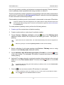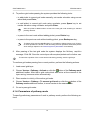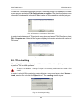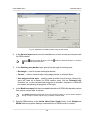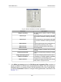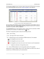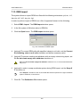
1
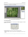
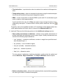
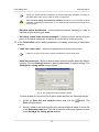
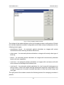
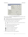
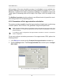
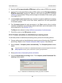
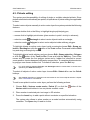
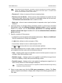
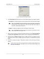
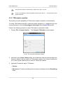
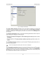
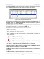
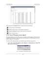
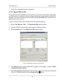
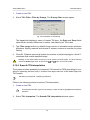
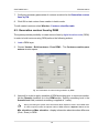
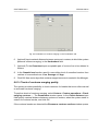
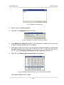
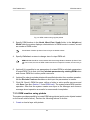
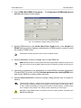
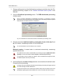
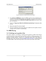
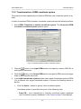
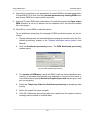
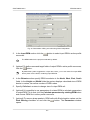
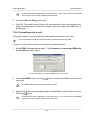
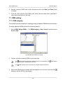
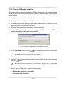
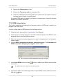
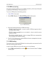
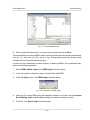
DTM Generation
PHOTOMOD 6.0.2
A list of erroneous nodes includes those located on all stereopairs of current project.
4. [optional] To change the list display parameters, click the
display changes in the list click the
button.
button. In order to
5. To edit TIN using the list the system provides the following features:
• to remove selected TIN node, click the
button or press the Delete key;
• to remove all nodes, where the error is more or equal to the error selected in the
list, click the
button.
6. Click the
button, to re-build the DEM considering all changes.
7.8.5. DEM control by vector objects
The system provides possibility to control DEM creation quality by comparing DEM
vertices coordinates with coordinates of vertices of vector objects layer. This vector
objects layer should not be used as a base layer during this DEM or TIN creation.
DEM control by vector objects is needed to estimate accuracy of imported DEM or, vice
versa, of vector objects by ’master’ DEM.
During comparing vector objects with DEM the system compares Z-coordinates of
pickets or vector objects vertices with elevation in corresponding points of the DEM.
To control DEM creation against vector objects perform the following actions:
1. Select DEM › Check accuracy › Check against vector objects. The Parameters
of check DEM by vectors window opens.
Fig. 116. Parameters of accuracy control by vectors
2. Set the following parameters:
• Display the worst..values – allows to show a list of specified number of pickets
with maximal error;
• Display with shift more than..m – allows to show a list of points with discrepancy
from DEM by Z greater than specified.
141