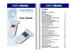
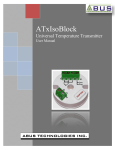
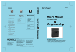
1
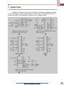
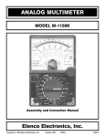
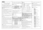
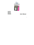
A4000 User Manual ABUS TECHNOLOGIES INC. A4000 WARNING This manual should be passed on to the end user. The contents of this manual are subject to change without prior notice. All rights reserved. ABUS gives no warranty of any kind with regard to this manual, including, but not limited to, fitness for a particular purpose. If any question arises or errors are found, or if any information is missing from this manual, please inform your supplier or inform at [email protected]. The specifications mentioned in this manual are limited to those for the standard type under the specified model number break-down and do not necessarily apply for customized instruments. Please note that changes in the specifications, construction, or component parts of the instrument may not immediately be reflected in this manual at the time of change. If the customer or any third party is harmed by the use of this product, ABUS assumes no responsibility for any such harm owing to any defects in the product which were not predictable, or for any indirect damages. The integral modules specifically HART module are not manufactured by ABUS. Although Warning hazards are related to personal injury, and Caution hazards are associated with equipment or property damage, it must be understood that operation of damaged equipment could, under certain operational conditions, result in degraded process system performance leading to personal injury or death. Therefore, comply fully with all Warning and Caution notices. Information in this manual is intended only to assist our customers in the efficient operation of our equipment. Use of this manual for any other purpose is specifically prohibited and its contents are not to be reproduced in full or part without prior approval of Technical Communications Department, ABUS Technologies HEALTH AND SAFETY To ensure that our products are safe and without risk to health, the following points must be noted: 1. The relevant sections of these instructions must be read carefully before proceeding. 2. Warning labels on containers and packages must be observed. 3. Installation, operation, maintenance and servicing must only be carried out by suitably trained personnel and in accordance with the information given. Any deviation from these instructions will transfer the complete liability to the user. 4. Normal safety precautions must be taken to avoid the possibility of an accident occurring when operating in conditions of high pressure and/or temperature. 5. Chemicals must be stored away from heat, protected from temperature extremes and powders kept dry. Normal safe handling procedures must be used. 6. When disposing of chemicals ensure that no two chemicals are mixed. Safety advice concerning the use of the equipment described in this manual or any relevant hazard data sheets (where applicable) may be obtained from the Company address on the back cover, together with servicing and spares information. ABUS TECHNOLOGIES INC. 2 A4000 . CATALOGUE Contents Page No. 1. Introduction 4 2. Presentation 4 4 Technical Parameters 3. Dimensions 5 4. Ordering Details 5 5. Connections 6 6. Installation 7 7 7 1. Input Signal 2. Function key and lamps 7. Configuration 1. Configuration Process 2. Key Operation Instructions 3. Programmable Curve Controller 4. Additional Notes 8. Operation Example for Usage 8 8 10 10 12 14 14 9. Maintenance Troubleshooting 15 10. Safety Precautions 16 11. Warranty 16 ABUS TECHNOLOGIES INC. 3 A4000 1. INTRODUCTION A4000 series is a Microprocessor based Digital Process Controller, which can be applied to high-precision measurement and control of temperature, pressure, discharge, liquid level and humidity etc... A four-digit LCD dual display indicates measured value and set-value for all programming parameters. Instrument configuration is achieved from the front panel keyboard, without any hardware change. The user should read this manual thoroughly before using the instrument. It must be handled with care and should be used accordingly for best results. 2. PRESENTATION Technical Parameters Display: Range: -1999 ~ 9999 Setting Mode: A: Panel Setting B: External Setting C: Programmable Curve Setting (Ramp & Soak) Isolation Output: One loop analogue or control output, resolution more than 12 digits. Current 0-20mA is adjustable, output impedance 600 Ohm. The unit only supplies 420mA and 0-20mA analogue output. If the user requires Voltage, he/she can connect impedance of 250 Ohm to get voltage 1-5V. (Accuracy depends on the impedance connected). Relay contact switch output: 250V/3A or 30VDC/3A. The main control output can be selected freely by the user. SSR pulse voltage output: 24VDC/30mA. SCR contact output: Can contact 5-500A SSR. Sampling Rate: <0.5S Control mode: PID control; Preset curve control; Pulse width control; Direct electronic machine control etc... The products can supply two wires isolate power 24V/30mA. Communication: RS485 (optional) Can calibrate Zero & Span and make it more reliable and accurate. Power: 85-265V AC/DC, consumption: <5VA Ambient Temperature: 0-50°C ABUS TECHNOLOGIES INC. 4 A4000 3. DIMENSIONS Weight Outline Dimension SIZE CODE A4000 – 4 A B C D E F G H 44+0.5 44+0.5 30 25 48 48 5 100 A4000 – 6 44+0.5 91+0.5 25 30 48 96 12 100 A4000 – 7 67.5+0.8 67.5+0.8 30 14 72 72 12 100 A4000 – 8 96 48 12 100 91+0.5 44+0.5 30 25 A4000 – 9 91+0.5 91+0.5 25 25 96 96 18 100 A4000 – 16 153.5+0.5 76+0.5 25 25 160 80 13.5 70 4. ORDERING DETAILS TYPE Product Size Power Supply Main Control Output Alarm Output DESCRIPTION A4000 A4000 Series 4 6 7 8 9 16 48W x 48H x 100L 48W x 48H x 100L 72W x 72H x 100L 96W x 48H x 100L 96W x 96H x 100L 160W x 80H x 70L D 85 ~ 265 Vac/dc C E F H N P L Y D R S K 0 2 Close loop direct 3-phase shift control 3-phase SCR contact control Ingle phase SCR contact control Open loop direct PWM time curve control Remote preset control Single phase shift control Current output Relay output SSR output SCR output None 2-Alarm. ABUS TECHNOLOGIES INC. 5 A4000 5. CONNECTIONS Connection (The final connection is according to the label on the product incase of any modification.) Every mode has one control output, 3 phase SCR control, 3phase shift control, direct electronic machine control, program control. ABUS TECHNOLOGIES INC. 6 A4000 6. INSTALLATION 6.1 Input Signal SIGNAL SELECTING SIGNAL TYPE RANGE RESOLUTION ACCURACY INPUT IMPEDANCE T/C b 600 ~ 1700°C 1°C 0.5% >100K B 5 R T E J T/C S 0 ~ 1700°C 1°C 0.5% >100K T/C R 500 ~ 1600°C 1°C 0.5% >100K T/C T 0.0 ~ 400.0°C 0.1°C 0.5% >100K T/C E 0 ~ 1000°C 1°C 0.5% >100K T/C J 0 ~ 1000°C 1°C 0.5% >100K T/C K 0 ~ 1200°C 1°C 0.5% >100K Pt T/C -200 ~ 600°C 0.1°C 0.5% Cu50/Cu100 Cu50/Cu100 -50.0 ~ 150°C 0.1°C 0.5% Ln or 0 ~ 400 Ω 0.5% 0.2mA -20 ~ 100mV 0.5% >100K 0-1V 0.5% >20K 0.5% >100K 0.5% >200K 0.5% <102Ω 0-5V 0-10V -1999 ~ 9999 12bit A/D FACTORY SETTING Yes 0.2mA Back 0-50mV 0-10V 0-10mA 0-20mA 4-20mA 4-20mA Note: 1. The resolution of R/S/B is 1°C; Resolution of the other signals is 0.1 in case the display is value less than 400. In case the display value more than 400, the resolution is 1°C, over range display or negative display can also be specified at the time of order.. 2. Pulse: Square wave, triangle wave, sine wave (need to mention when order), rating more than 4V or less than IV. Frequency Range: 0-60KHz. 6.2 Function Keys and Lamps 6.2.1 KEYS A: SET: Set Key B: ▲/▼: Increase/Decrease Key C: SET+▲: Hold the set key, press ▲ will shift digit. D: LED flashes, press SET key to confirm Parameter. E: The digit shifts to another one to be modified. 6.2.2 LAMPS SV red lamp On: Indicate the set value; Flash: Indicate the external setting input value (the second input value of loop 2). MV red lamp On: Indicate control output value. In case it is manual manipulation, it indicate the manipulate. MAN green lamp On: Manual manipulate; Flash: In the case of auto-tune; Off: automatism. ABUS TECHNOLOGIES INC. 7 A4000 7. CONFIGURATION 7.1 Configuration Process Self-Check when Power is On PID Parameter setting mode ABUS TECHNOLOGIES INC. 8 A4000 Calibrate Menu Setting Mode ABUS TECHNOLOGIES INC. 9 A4000 7.2 Key Operation Instruction 7.2.1 KEY OPERATION PROCEDURE 1. When the unit is in the state of measuring, please SET key for 3 seconds to enter parameters P, I, D… 2. Press SET key to select the parameter that to be modified. Hold SET key and press increase key, LED flashes, as the same operations, it shift to another digit, press increase/decrease to modify the value. Press SET key to confirm. 3. In the menu of parameter adjustment, select parameter LCK, when LCK=000 or LCK=010, in the state of manipulation (MAN lamp on), press SET key for 3 seconds to enter calibrate parameter menu. Modification of the parameters, same as in above, i.e. Step 2. 4. The unit will go back to the measuring estate without any operation for 5 seconds. 5. In PID adjust and calibrate menu, if LCK=010, all parameters for read only, but not for modification. Anyway, the value of LCK can be modified by the user. 7.2.2 FUNCTION OPERATIONS 1. To convert the displaying windows: Press SET key, SV lamp on indicates the setting value; MV lamp on indicates control output values; SV lamp flash indicates the measuring value of loop input. 2. When SV lamp is On, the procedure of modification is same as Key Operations. 3. MV value modification: MV lamp On, and if it is manual manipulation (MAN lamp On), please modify, referring the procedure of Key Operations. 4. Auto/Manual manipulate convert is On: Manual Tune; Off: Auto –tune, Press A/M key to convert. 5. Auto adjust operation: Press SET key for 3 seconds, enter parameter P, I, D… Set P 6 0, then press SET key to select parameter AT and set AT=1, MAN lamp flashes, it means that the unit is in auto-tune state. Press SET key to quit. At this moment, please don’t perform any key operation and wait for auto-adjust to complete. When auto-adjust is finished, MAN lamp is Off, the unit refreshes the PID value by itself. 6. Auto when power On: When the system is running, if user wants to switch auto-tune immediately, please do as following: Enter P, I, D…Press Set key to select parameter MAN and set MAN=1. On the other hand, if you want manual manipulate, set MAN=0. 7.3 Programmable Curve Controller Key Operations: 1. SET key: Parameter Select/Confirm key. 2. Press SET key and increase key at the same time, LED flashes, the value can be modified. Hold SET key and then press increase key to shift to the digit you want to modify. ABUS TECHNOLOGIES INC. 10 A4000 3. Increase/Decrease key to modify the value. 4. A/M key: Auto manipulate convert key, when the program is running, it will pause (MAN lamp On). Press A/M key, it will continue running (MAN lamp off). 5. Press SET key and A/M key at the same time to turn On/Off the program. The key operation is not available when its non-program running. 6. Curve setting method: In the ofline state, press ▲/▼ key at the same time, the SV window displays in and enter the parameter setting area, press SET key to select the parameter SV00 and begin to set the parameter of curve. 7. In the course of setting, SET is a curve parameter selection key. 8. When the setting is finished, press ▲/▼ key at the same time. To quit. 12 Segments of program curve, running parameter are as under: In the table, the curve is “free” set by the user. SV00 is the beginning of the curve running. TM00 is the time SV00 to SV01. TM01 is the time from SV01 to SV02... SVXX: Stands for the value of each turning point. It should belong to the range of measuring (FL1 to FH1). TMXX: Stands for the running time of each stage. The range of timing is 0.0-540 minutes or more. The program will come to end in case the next turning point is set to 0. For example, there are only 4 stages. You should set TM04=0, meanwhile SV04 ≠ 0, then the program comes to end. To set TMXX=0: Shift the flashing digit to the left, press decrease key till it displays 0. Before grogram starts: Normal operation, is set ehemeter in auto-tune state, running the system with the controller in a set point to acquire the value of P, I, D. Output when program starts: Before start, the user can set the output value as he wants. Manipulate steps: set MV value as to pre-heat, if the user wants always heating before program starting, he can set MV=100. Program pauses: During the course of program running, press A/M key can pause running and MAN lamp is On. At this moment, the user can modify the control output value by manipulate; the unit will wait for other action such as heating, running stage and Preset stops when program pauses. Program continues: When the program pauses, press A/M key can make it continue to run the program. MAN lamp is Off. Program ends: When the program reaches the end of the last stage, or reaches the next stage that is set value 0, the program will come to end. At this moment the unit will display “END”. Meanwhile output stops, and alarm 2 takes action. Displaying convert: Press SET key to select the parameters. SV lamp On indicates preset value of the parameter, SV lamp flashes indicates parameter of running stage. MV lamp On indicates the control output value. AL1 and AL2: In non-programmable curve control, AL1 and AL2 are used for the 4 Alarm modes. In programmable curve control, AL1 is used for normal style of alarm; AL2 is used for alarming program ends. ABUS TECHNOLOGIES INC. 11 A4000 7.4 Additional Notes 7.4.1 Additional A4000/A4000 16-bit input signal selection 7.4.2 Additional notes of manipulate operator/ electronic-machine driver. 1. When the adjustor is a non-electronic machine control output, all key operations are the same as stated before. 2. When the adjustor is non-electronic machine (required the electronic machine driver must have Low-High location equipment.) control output, some parameters should be modified as follows: HY: Ct: AL1: OUTL: AL2: OUTH: OUT: Blind spot of motor control setting. Range: 1.0-5.0% The running time of full open to full close to full open. Range: 20-250 seconds. Normal alarm mode. Value output law value. Range: 0.0 ~ 50.0%. Change to motor positive-tune control. Value output high value. Range: 30.0 ~ 100.0% Motor reverse-turn control. 3. Displaying operations: PV displays the measuring value. SV lamp on displaying preset value, SV lamp flashes displaying value feedback value, MV lamp on displaying control output value. ABUS TECHNOLOGIES INC. 12 A4000 Manual Manipulation: MAN lamp On means manual manipulation. Press SET key select MV lamp is On, at this moment the window can be set to show the present between the total power on running time and the whole running time of the motor or value. The percent shows the location value of the value. When changing the manual manipulate value, the unit will stop after running the set timing. When it is auto-tune, it displays the running location value of value. Auto-tune: the unit runs as PID mode Auto/manual manipulate converts: Press A/M key to convert. 4. Value feedback signal calibrations Feedback signal voltage/current: When it is input by voltage 0-5V, 1-5V, 0-10V or current 0-10mA, 4-20mA, the unit should be calibrated by the factory. Otherwise the user should calibrate on the spot. Feedback impedance of value is less than 1K, the user should calibrate on the spot. Steps are as follows: Connect all wires, according to the instructions in manual. And then switch on the power. Press A/M key to make Man lamp On. Press SET key for more than 3 seconds entering parameter P,I,D...Select LCK and set LCK=000, and then press SET key for more than 3 seconds again to enter the parameter calibrate area. Press SET key to select IN1, set IN1=rt, it means impedance input. Press SET key, select and select nL1. At this moment, value motor will close. Waiting for full range running time, till low location switch takes action. Then press SET key to confirm. The unit will display 0.0 (low values calibrate) at this moment. Press SET key, select nH1. At this moment, value motor will open. Waiting for full range running time, till high location switch takes action. Then press SET and increase key at the same time, LED flashes, press SET key to confirm. The unit will display 100.0 (high value calibrate) at this moment. Feedback impedance of value is more than 1K External impedance should be used to share partly of the full voltage to make it about 60mV. Select the input signal IN1=Ln, and then calibrate as mentioned above. ABUS TECHNOLOGIES INC. 13 A4000 Control wire connections (control mode convert BSET1.6=1 means open control, BSET1.6=0 means close control) 7.4.3 Remote control operations: 1. Remote control setting: Set parameter BSET1.7=1 and it means the unit for remote control. The factory has set this parameter before sales. 2. Remote control connection wires: In normally, the remote control input is connected to the terminal +5V, GND and mA according to the voltage/current input. 3. Remote input displaying: SV and MV windows display remote input value, press SET key to select, when SV flashes, the SV window displays remote control value. This is set by input value of parameters IN2, FL2, FH2 and nH2. 4. Error elimination of faulty wire connection: In this case the input signal exceeds the range of measuring, the unit will cancel external setting function. It changes to internal panel setting. It will not display external value at this moment. SV lamp On means, that it can change the setting value. 8. OPERATION Example for Usage Relay Control ABUS TECHNOLOGIES INC. 14 A4000 The connection of SCR The connection of SCR Heating Control 9. MAINTENANCE Troubleshooting INFORMATION SPECIFICATIONS ELIMINATE Sensor not connected or input signal is too low. Check and connect the sensor properly, or reset the low alarm value. Sensor not connected or input signal is too high. Check and connect the sensor properly, or reset the high alarm value. ABUS TECHNOLOGIES INC. 15 A4000 10. SAFETY PRECAUTIONS 1. The unit should be powered for 15 minutes before use. 2. Use in ambient temperature of 0-60˚C. 3. Avoid vibrations, shock, excessive dust, corrosive chemical materials or gaseous environment. 4. Input wire should not be too long. If measured signal have to be far away from the unit, please use 2-core shielded cable. 5. Use this instrument in the scope of its specifications, otherwise fire or malfunctions may result. 6. Contact of the instrument, with organic solvents or oils should be avoided. 7. Do not turn on the power supply until all of the wiring is completed. Otherwise electrical shock, fire or malfunction may result. 8. Do not disassemble, repair or modify the instrument. 9. All connections should be tightened properly. 10. Power supply should be constant, should not be fluctuating. 11. WARRANTY ABUS provides the original purchaser of this instrument a one (1) year warranty against defects in material and workmanship under the following terms: The one year warranty begins on the day of shipment as stated on the sales bill. During the warranty period all costs of material and labor will be free of charge provided that the instrument does not show any evidence of misuse. For maintenance, return the instrument with a copy of the sales bill to our factory. All transportation and insurance costs should be covered by the owner of the equipment. Should any sign of electrical or mechanical shock, abuse, bad handling or misuse be evident the warranty voids and maintenance costs will be charged. ABUS TECHNOLOGIES INC. www.abustek.com, E-Mail: [email protected] ABUS TECHNOLOGIES INC. 16