1
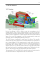
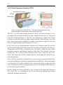
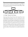
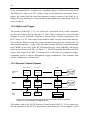
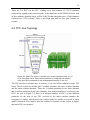
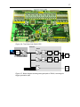
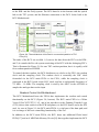
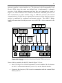
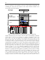
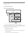
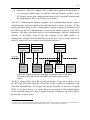
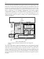
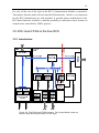
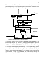
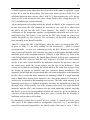
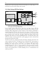
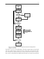
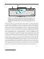
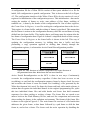
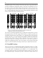
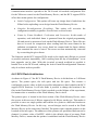
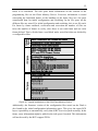
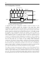
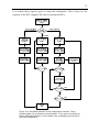
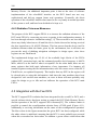
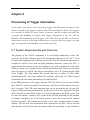
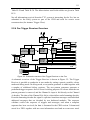
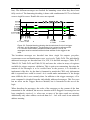
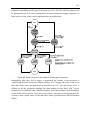
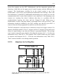
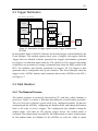
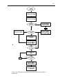
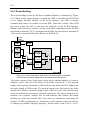
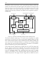
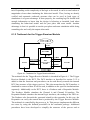
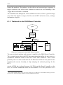
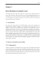
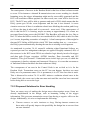
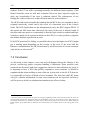
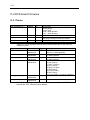
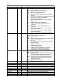
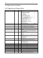
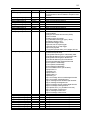
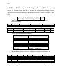
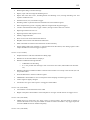
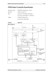
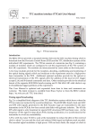
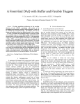
121
5.3 Trigger Distribution
Up to 28 FECs on two branches
FEC
RCU Motherboard
Readout node
ALTRO 1
ALTRO bus
ALTRO 2
ALTRO
Interface
L2a/
L0 L1 L2r
SW trigger
Event
Manager
L0 L1
ALTRO N
Board
Controller
Trigger
Receiver
Module
HW trigger
DCS board
L2a/
L2r
Channel A
TTCrx
Optical link
Trigger
System
Channel B
Figure 5-7: Distribution of trigger signals from the Trigger System to the
ALTROs.
In the Readout Node of the RCU firmware the decoded trigger is then handled by the
Event Manager. This module supports three types of triggers: the triggers from the
Trigger Receiver Module, software generated test triggers and hardware generated
test triggers via dedicated input connector. The software L0/L1a triggers (depending
on detector) are generated by issuing a command from either the DAQ system or the
DCS. For hardware and software generated test triggers, the L2a trigger is then
generated after a configurable time by the firmware. The Event Manager sends the
triggers to the ALTRO interface that broadcasts them to the ALTROs on the FECs,
see Figure 5-7.
5.4 Data Readout
5.4.1 The Readout Process
The readout sequence is extensively discussed in [13], and only a short summary is
given here. Figure 5-8 shows a flowchart describing the overall readout procedure.
The very first step is that the system needs to be configured properly. In that lies
configuring all the ALTROs, configuring the Readout Node, and arming the Readout
Node to be ready to receive triggers. The configuration also includes setting the
readout mode, and when an L2a physics trigger arrives, the readout mode is
evaluated. The readout mode can either be full readout mode or sparse readout mode.
In full readout mode, all channels of all ALTROs are read out, while in sparse