1
User Guide
AV SWITCHERS
MLS 608 D SERIES
AV Switchers with ProDSP™
(with the MTP/HDMI U R receiver)
MLS 608 D SA
MTP/HDMI U R
68-1893-01 Rev. A
12 11
Precautions
Safety Instructions • English
Warning
This symbol is intended to alert the user of important operating and maintenance
(servicing) instructions in the literature provided with the equipment.
Power sources • This equipment should be operated only from the power source indicated on the product. This
equipment is intended to be used with a main power system with a grounded (neutral) conductor. The third
(grounding) pin is a safety feature, do not attempt to bypass or disable it.
This symbol is intended to alert the user of the presence of uninsulated dangerous
voltage within the product’s enclosure that may present a risk of electric shock.
Power disconnection • To remove power from the equipment safely, remove all power cords from the rear of the
equipment, or the desktop power module (if detachable), or from the power source receptacle (wall plug).
Caution
Read Instructions • Read and understand all safety and operating instructions before using the equipment.
Retain Instructions • The safety instructions should be kept for future reference.
Follow Warnings • Follow all warnings and instructions marked on the equipment or in the user information.
Avoid Attachments • Do not use tools or attachments that are not recommended by the equipment
manufacturer because they may be hazardous.
Consignes de Sécurité • Français
Power cord protection • Power cords should be routed so that they are not likely to be stepped on or pinched by
items placed upon or against them.
Servicing • Refer all servicing to qualified service personnel. There are no user-serviceable parts inside. To prevent
the risk of shock, do not attempt to service this equipment yourself because opening or removing covers may
expose you to dangerous voltage or other hazards.
Slots and openings • If the equipment has slots or holes in the enclosure, these are provided to prevent
overheating of sensitive components inside. These openings must never be blocked by other objects.
Lithium battery • There is a danger of explosion if battery is incorrectly replaced. Replace it only with the same or
equivalent type recommended by the manufacturer. Dispose of used batteries according to the manufacturer’s
instructions.
Avertissement
Ce symbole sert à avertir l’utilisateur que la documentation fournie avec le
matériel contient des instructions importantes concernant l’exploitation et la
maintenance (réparation).
Alimentations• Ne faire fonctionner ce matériel qu’avec la source d’alimentation indiquée sur l’appareil. Ce
matériel doit être utilisé avec une alimentation principale comportant un fil de terre (neutre). Le troisième
contact (de mise à la terre) constitue un dispositif de sécurité : n’essayez pas de la contourner ni de la
désactiver.
Ce symbole sert à avertir l’utilisateur de la présence dans le boîtier de l’appareil
de tensions dangereuses non isolées posant des risques d’électrocution.
Déconnexion de l’alimentation• Pour mettre le matériel hors tension sans danger, déconnectez tous les cordons
d’alimentation de l’arrière de l’appareil ou du module d’alimentation de bureau (s’il est amovible) ou encore de
la prise secteur.
Attention
Lire les instructions• Prendre connaissance de toutes les consignes de sécurité et d’exploitation avant d’utiliser
le matériel.
Conserver les instructions• Ranger les consignes de sécurité afin de pouvoir les consulter à l’avenir.
Respecter les avertissements • Observer tous les avertissements et consignes marqués sur le matériel ou
présentés dans la documentation utilisateur.
Eviter les pièces de fixation • Ne pas utiliser de pièces de fixation ni d’outils non recommandés par le fabricant
du matériel car cela risquerait de poser certains dangers.
Sicherheitsanleitungen • Deutsch
Protection du cordon d’alimentation • Acheminer les cordons d’alimentation de manière à ce que personne ne
risque de marcher dessus et à ce qu’ils ne soient pas écrasés ou pincés par des objets.
Réparation-maintenance • Faire exécuter toutes les interventions de réparation-maintenance par un technicien
qualifié. Aucun des éléments internes ne peut être réparé par l’utilisateur. Afin d’éviter tout danger
d’électrocution, l’utilisateur ne doit pas essayer de procéder lui-même à ces opérations car l’ouverture ou le
retrait des couvercles risquent de l’exposer à de hautes tensions et autres dangers.
Fentes et orifices • Si le boîtier de l’appareil comporte des fentes ou des orifices, ceux-ci servent à empêcher les
composants internes sensibles de surchauffer. Ces ouvertures ne doivent jamais être bloquées par des objets.
Lithium Batterie • Il a danger d’explosion s’ll y a remplacment incorrect de la batterie. Remplacer uniquement
avec une batterie du meme type ou d’un ype equivalent recommande par le constructeur. Mettre au reut les
batteries usagees conformement aux instructions du fabricant.
Vorsicht
Dieses Symbol soll dem Benutzer in der im Lieferumfang enthaltenen
Dokumentation besonders wichtige Hinweise zur Bedienung und Wartung
(Instandhaltung) geben.
Stromquellen • Dieses Gerät sollte nur über die auf dem Produkt angegebene Stromquelle betrieben werden.
Dieses Gerät wurde für eine Verwendung mit einer Hauptstromleitung mit einem geerdeten (neutralen) Leiter
konzipiert. Der dritte Kontakt ist für einen Erdanschluß, und stellt eine Sicherheitsfunktion dar. Diese sollte nicht
umgangen oder außer Betrieb gesetzt werden.
Dieses Symbol soll den Benutzer darauf aufmerksam machen, daß im Inneren
des Gehäuses dieses Produktes gefährliche Spannungen, die nicht isoliert sind
und die einen elektrischen Schock verursachen können, herrschen.
Stromunterbrechung • Um das Gerät auf sichere Weise vom Netz zu trennen, sollten Sie alle Netzkabel aus der
Rückseite des Gerätes, aus der externen Stomversorgung (falls dies möglich ist) oder aus der Wandsteckdose
ziehen.
Achtung
Lesen der Anleitungen • Bevor Sie das Gerät zum ersten Mal verwenden, sollten Sie alle Sicherheits-und
Bedienungsanleitungen genau durchlesen und verstehen.
Aufbewahren der Anleitungen • Die Hinweise zur elektrischen Sicherheit des Produktes sollten Sie
aufbewahren, damit Sie im Bedarfsfall darauf zurückgreifen können.
Befolgen der Warnhinweise • Befolgen Sie alle Warnhinweise und Anleitungen auf dem Gerät oder in der
Benutzerdokumentation.
Keine Zusatzgeräte • Verwenden Sie keine Werkzeuge oder Zusatzgeräte, die nicht ausdrücklich vom Hersteller
empfohlen wurden, da diese eine Gefahrenquelle darstellen können.
Instrucciones de seguridad • Español
Schutz des Netzkabels • Netzkabel sollten stets so verlegt werden, daß sie nicht im Weg liegen und niemand
darauf treten kann oder Objekte darauf- oder unmittelbar dagegengestellt werden können.
Wartung • Alle Wartungsmaßnahmen sollten nur von qualifiziertem Servicepersonal durchgeführt werden. Die
internen Komponenten des Gerätes sind wartungsfrei. Zur Vermeidung eines elektrischen Schocks versuchen
Sie in keinem Fall, dieses Gerät selbst öffnen, da beim Entfernen der Abdeckungen die Gefahr eines
elektrischen Schlags und/oder andere Gefahren bestehen.
Schlitze und Öffnungen • Wenn das Gerät Schlitze oder Löcher im Gehäuse aufweist, dienen diese zur
Vermeidung einer Überhitzung der empfindlichen Teile im Inneren. Diese Öffnungen dürfen niemals von
anderen Objekten blockiert werden.
Litium-Batterie • Explosionsgefahr, falls die Batterie nicht richtig ersetzt wird. Ersetzen Sie verbrauchte Batterien nur
durch den gleichen oder einen vergleichbaren Batterietyp, der auch vom Hersteller empfohlen wird. Entsorgen
Sie verbrauchte Batterien bitte gemäß den Herstelleranweisungen.
Advertencia
Este símbolo se utiliza para advertir al usuario sobre instrucciones importantes
de operación y mantenimiento (o cambio de partes) que se desean destacar en
el contenido de la documentación suministrada con los equipos.
Alimentación eléctrica • Este equipo debe conectarse únicamente a la fuente/tipo de alimentación eléctrica
indicada en el mismo. La alimentación eléctrica de este equipo debe provenir de un sistema de distribución
general con conductor neutro a tierra. La tercera pata (puesta a tierra) es una medida de seguridad, no
puentearia ni eliminaria.
Este símbolo se utiliza para advertir al usuario sobre la presencia de elementos
con voltaje peligroso sin protección aislante, que puedan encontrarse dentro
de la caja o alojamiento del producto, y que puedan representar riesgo de
electrocución.
Desconexión de alimentación eléctrica • Para desconectar con seguridad la acometida de alimentación eléctrica
al equipo, desenchufar todos los cables de alimentación en el panel trasero del equipo, o desenchufar el
módulo de alimentación (si fuera independiente), o desenchufar el cable del receptáculo de la pared.
Precaucion
Leer las instrucciones • Leer y analizar todas las instrucciones de operación y seguridad, antes de usar el
equipo.
Conservar las instrucciones • Conservar las instrucciones de seguridad para futura consulta.
Obedecer las advertencias • Todas las advertencias e instrucciones marcadas en el equipo o en la
documentación del usuario, deben ser obedecidas.
Evitar el uso de accesorios • No usar herramientas o accesorios que no sean especificamente recomendados
por el fabricante, ya que podrian implicar riesgos.
安全须知 • 中文
这个符号提示用户该设备用户手册中有重要的操作和维护说明。
这个符号警告用户该设备机壳内有暴露的危险电压,有触电危险。
注意
阅读说明书 • 用户使用该设备前必须阅读并理解所有安全和使用说明。
保存说明书 • 用户应保存安全说明书以备将来使用。
遵守警告 • 用户应遵守产品和用户指南上的所有安全和操作说明。
避免追加 • 不要使用该产品厂商没有推荐的工具或追加设备,以避免危险。
Protección del cables de alimentación • Los cables de alimentación eléctrica se deben instalar en lugares donde
no sean pisados ni apretados por objetos que se puedan apoyar sobre ellos.
Reparaciones/mantenimiento • Solicitar siempre los servicios técnicos de personal calificado. En el interior no
hay partes a las que el usuario deba acceder. Para evitar riesgo de electrocución, no intentar personalmente la
reparación/mantenimiento de este equipo, ya que al abrir o extraer las tapas puede quedar expuesto a voltajes
peligrosos u otros riesgos.
Ranuras y aberturas • Si el equipo posee ranuras o orificios en su caja/alojamiento, es para evitar el
sobrecalientamiento de componentes internos sensibles. Estas aberturas nunca se deben obstruir con otros
objetos.
Batería de litio • Existe riesgo de explosión si esta batería se coloca en la posición incorrecta. Cambiar esta batería
únicamente con el mismo tipo (o su equivalente) recomendado por el fabricante. Desachar las baterías usadas
siguiendo las instrucciones del fabricante.
警告
电源 • 该设备只能使用产品上标明的电源。 设备必须使用有地线的供电系统供电。 第三条线(
地线)是安全设施,不能不用或跳过 。
拔掉电源 • 为安全地从设备拔掉电源,请拔掉所有设备后或桌面电源的电源线,或任何接到市电
系统的电源线。
电源线保护 • 妥善布线, 避免被踩踏,或重物挤压。
维护 • 所有维修必须由认证的维修人员进行。 设备内部没有用户可以更换的零件。为避免出现触
电危险不要自己试图打开设备盖子维修该设备。
通风孔 • 有些设备机壳上有通风槽或孔,它们是用来防止机内敏感元件过热。 不要用任何东西
挡住通风孔。
锂电池 • 不正确的更换电池会有爆炸的危险。必须使用与厂家推荐的相同或相近型号的电池。按
照生产厂的建议处理废弃电池。
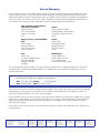
FCC Class A Notice
This equipment has been tested and found to comply with the limits for a Class A digital device, pursuant to part 15
of the FCC Rules. Operation is subject to the following two conditions:
1. This device may not cause harmful interference.
2. This device must accept any interference received, including interference that may cause undesired operation.
The Class A limits are designed to provide reasonable protection against harmful interference when the equipment
is operated in a commercial environment. This equipment generates, uses, and can radiate radio frequency energy
and, if not installed and used in accordance with the instruction manual, may cause harmful interference to radio
communications. Operation of this equipment in a residential area is likely to cause harmful interference, in which
case the user will be required to correct the interference at his own expense.
NOTE: This unit was tested with shielded cables on the peripheral devices. Shielded cables must be used with the
unit to ensure compliance with FCC emissions limits.
.
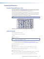
Conventions Used in this Guide
In this user guide, the following are used:
NOTE: A note draws attention to important information.
TIP:
A tip provides a suggestion to make working with the application easier.
CAUTION: A caution indicates a potential hazard to equipment or data.
WARNING: A warning warns of things or actions that might cause injury, death, or
other severe consequences.
Commands are written in the fonts shown here:
^AR Merge Scene,,Op1 scene 1,1 ^B 51 ^W^C
[01] R 0004 00300 00400 00800 00600 [02] 35 [17] [03]
E X! *X1&* X2)* X2#* X2! CE}
NOTE: For commands and examples of computer or device responses mentioned
in this guide, the character “0” is used for the number zero and “O”
represents the capital letter “o.”
Computer responses and directory paths that do not have variables are written in the font
shown here:
Reply from 208.132.180.48: bytes=32 times=2ms TTL=32
C:\Program Files\Extron
Variables are written in slanted form as shown here:
ping xxx.xxx.xxx.xxx —t
SOH R Data STX Command ETB ETX
Selectable items, such as menu names, menu options, buttons, tabs, and field names are
written in the font shown here:
From the File menu, select New.
Click the OK button.
Copyright
© 2011 Extron Electronics. All rights reserved.
Trademarks
All trademarks mentioned in this guide are the properties of their respective owners.
Introduction............................................................ 1
DSP Configurator™.............................................. 44
MLS 608 D Series Description............................... 1
Features............................................................... 1
Controlling the MLS 608 D Series Switcher.......... 3
MLS 608 D SA Application Diagram
.......................................................................... 4
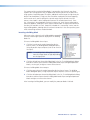
Installing the Software....................................... 44
Installation From the DVD.............................. 44
Installation from the Website......................... 45
Starting the DSP Configurator............................ 45
Using the DSP Configurator Software................ 47
Orientation.................................................... 47
Workspace Menus......................................... 48
MTP Video Settings........................................ 57
HDCP Compliance......................................... 59
Video Signal Presence.................................... 60
PRELIMINARY
Installation............................................................... 5
UL/Safety Requirements....................................... 5
Mounting the MLS 608 D Series Switchers........... 6
Tabletop Placement.......................................... 6
UL Guidelines for Rack Mounted Devices ........ 6
Rack Mounting................................................ 6
SIS Programming and Control........................... 61
MLS 608 D Series Rear Panel Features.................. 7
Power, Analog, and Digital Connections........... 8
Audio and RS-232 Connections..................... 14
MTP/HDMI U R Connections.............................. 17
Power Save Mode.......................................... 19
Host to MLS 608 D Communications................. 61
MLS 608 D Switcher-initiated Messages......... 61
Error Responses............................................. 62
Error Response References............................. 62
Command and Responses.................................. 63
Using the Command/Response Tables............ 63
Symbol Definitions......................................... 63
Command Response Table for SIS Commands.... 69
Operation............................................................... 20
User Interface Navigation.................................. 77
Front Panel Features and Operation................... 20
Using EDIDs....................................................... 22
EDID Minder.................................................. 22
Automatic EDID Mode (digital output only).... 24
User Assigned EDID Mode.............................. 24
Importing EDID Data...................................... 25
Exporting EDID Data ..................................... 25
Updating the EDID Table................................ 26
Optimizing Audio — An Overview..................... 27
Workspaces................................................... 27
DSP Signal Chain........................................... 28
Building Blocks — An Overview..................... 31
Group Masters — An Overview...................... 35
Optimizing Video — An Overview...................... 40
Setting the Peaking and Level on
the MTP/HDMI U R........................................ 40
Setting the Skew on the MLS 608 D............... 41
Selecting the MLS 608 D Output PrePeak....... 41
Firmware Upgrades............................................ 42
Updating Firmware........................................ 42
Mouse and Keyboard Navigation....................... 77
Selecting Multiple Blocks................................ 77
Selecting Multiple Areas................................. 77
Copying a Block of Elements.......................... 78
Cutting a Block of Elements........................... 78
Pasting to a Single Location........................... 78
Pasting to Multiple Locations......................... 79
Keyboard Shortcuts............................................ 80
Rear Panel Connections........................................ 7
Button Labels........................................................ 82
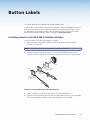
Installing Labels in the MLS 608 D
Switcher Buttons.............................................. 82
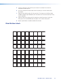
Blank Button Labels........................................... 83
Reference Material.............................................. 84
Part Numbers and Accessories............................ 92
Included Parts................................................ 92
Optional Parts................................................ 92
MLS 608 D Series • Contents
v
PRELIMINARY
Contents
MLS 608 D Series • Contents
vi
Introduction
This manual contains information about the Extron MLS 608 D Series of AV switchers with
instructions for experienced installers on how to install, configure, and operate it.
In this manual the terms “MLS 608 D Series switcher,” “AV switcher,” and “switcher” are
used interchangeably and refer to any of the MLS 608 D Series models.
MLS 608 D Series Description
The MLS 608 D AV switchers are available in three models:
zz
MLS 608 D — a non-amplified model with variable preamp outputs.
zz
MLS 608 D SA — features 2-channel stereo power amplification with 20 watts rms
per channel into 4 or 8 ohms.
zz
MLS 608 D MA — features mono 70 volt amplification with 40 watts rms output.
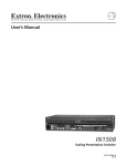
The MLS 608 D series are simple-to-use, eight input, multi-format switchers designed to
integrate digital and analog sources. All signals are transmitted over CAT 5-type cable to
the included MTP/HDMI U R Twisted Pair Receiver. The MLS 608 D Series feature Extron
ProDSP™ digital audio processing, which provides an extensive array of easy-to-use
tools for audio system setup and fine-tuning. The MLS 608 D Series offers digital video
switching with four HDCP-compliant HDMI inputs, and analog video switching with four
universal inputs, including an Extron universal MTP twisted pair input. It outputs HDMI
twisted pair signals and analog MTP Twisted Pair to the included MTP/HDMI U R receiver,
providing a complete digital and analog video and audio switching system.
The MLS 608 D AV switchers are ideal for classrooms and other AV environments that
require the flexibility to integrate digital and analog video switching in a single switcher.
Features
zz
Inputs: Three 15-pin HD connectors – one with loop-through – for RGBHV, HDTV
component video, and S-video or composite video; one universal MTP twisted
pair input, four HDMI connectors; seven captive screw connectors for balanced or
unbalanced stereo audio; one balanced or unbalanced mono audio input via MTP
zz
Outputs:
MLS 608 D switcher — One buffered output on VGA connector (tied only to
input 1), two balanced or unbalanced audio outputs on captive screw connectors,
analog MTP video and audio output on one RJ-45 connector, digital video and
RS-232 on two RJ-45 connectors, one power amplifier output ( MA and SA models
only).
MTP/HDMI U R receiver — RGB on 15-pin HD, component video on BNCs, S-video
on 4-pin mini DIN, composite video on BNC, HDMI connector, balanced or unbalanced
audio on one captive screw connector, communications on a captive screw connector.
zz
Multi-input switcher for digital and analog video signals
zz
Transmits HDMI and analog video plus audio and RS-232 over CAT 5-type cables.
zz
Includes MTP/HDMI U R Twisted Pair Receiver — Automatically routes incoming
signals to the appropriate output connectors.
MLS 608 D Series • Introduction
1
zz
EDID Minder® — Automatically manages EDID – Extended Display Identification Data
– communication between the display and connected VGA and HDMI input sources.
EDID Minder ensures that all sources power up correctly and reliably output content,
whether or not they are actively connected to the display device through the switcher
outputs.
zz
HDMI audio de-embedding — Strips two-channel PCM audio off HDMI inputs,
allowing for DSP processing and signal routing.
zz
HDCP compliance — The MLS 608 D switchers and the included MTP/HDMI U R
device fully support switching and long distance transmission of HDCP signals.
zz
Cable equalization for each HDMI input — Actively conditions incoming HDMI
signals to compensate for signal loss when using long HDMI cables, low quality HDMI
cables, or source devices with poor HDMI signal output.
zz
Sends 720p, 1080i, and XGA (1024x768) HDMI signals up to 200 feet
(60 meters), 1080p/60 and 1920x1200 HDMI signals up to 100 feet (30 meters)
with standard CAT 5e cable — Extron STP201 Digital Twisted Pair cable provides
added protection from outside interference and increases overall signal transmission
distance.
zz
Four input analog universal video switching — Four universal inputs, including
an Extron universal MTP twisted pair, accept RGBHV, HDTV component video, and
S-video or composite video sources. The output is universal MTP twisted pair to the
included MTP/HDMI U R.
zz
Controllable (via TouchLink™ Control System, MediaLink® Controller, front
panel buttons, or RS-232) — The switchers can be controlled using the front panel
backlit buttons or RS-232. An optional TouchLink Touchpanel Control System or
MediaLink Controller may be connected to the RS-232 port to provide a simple and
intuitive user interface for the MLS 608 D Switchers, and the entire room.
zz
Skew equalization for MTP input and output — Skew adjustments are stored in
memory for the MTP input and output, to maintain RGB color alignment at all times.
zz
Separate variable level and peaking controls for analog MTP signals
zz
Front panel control with backlit buttons — The buttons can be custom-labeled for
easy identification. Because the buttons illuminate, they are helpful for presenters in
low-light environments.
zz
Audio switching and output volume control — The MLS 608 D Series features
audio switching for eight input sources, and provides master volume control and
muting. Three balanced or unbalanced outputs are available, two on the MLS 608 D
switchers, the third on the MTP/HDMI U R. Each output can be set as variable or fixed.
zz
Audio input gain and attenuation — Gain or attenuation can be adjusted for each
input to eliminate noticeable differences when switching between sources.
zz
Mic/line audio matrix mixing — The MLS 608 D switchers provide microphone
bussing so that each of the two mic/line inputs can be mixed into any or all of the
audio outputs.
zz
Available with integrated stereo or mono 70 volt power amplifier — The
MLS 608 D SA offers a stereo power amplifier with 20 watts rms output per channel
into 4 or 8 ohms. The MLS 608 D MA offers a mono 70 volt power amplifier with
40 watts rms output. Both feature an Extron exclusive, highly efficient, advanced
Class D amplifier design with CDRS™ - Class D Ripple Suppression, an Extron patented
technology that provides a smooth, clean audio waveform and an improvement in
signal fidelity over conventional Class D amplifier designs. CDRS eliminates the high
frequency switching ripple characteristic of Class D amplifiers, a source of radio
frequency (RF) emissions which can interfere with sensitive AV equipment such as
wireless microphones.
MLS 608 D Series • Introduction
2
zz
Essential audio DSP tools — ProDSP provides an extensive array of easy-to-use,
digital audio processing tools for audio system setup and fine-tuning, including audio
gain, dynamics, compression, filtering, delay, microphone ducking, loudness, and
feedback suppression.
zz
DSP Configurator™ Software — A powerful yet user-friendly software tool for
managing all audio setup and operations of the MLS 608 D SA, it enables complete
setup and configuration of digital audio processing tools on the ProDSP platform as
well as microphone mixing.
zz
Front panel USB configuration port — Provides convenient access for system setup
and configuration, as well as ProDSP for audio system integration.
zz
Plenum rated MTP/HDMI U R receiver — meets UL 2043 for heat and smoke
release, excluding power supply
zz
Rack-mountable 2U, full rack width metal enclosure
zz
Internal universal power supply — The 100-240 VAC, 50-60 Hz, international
power supply provides worldwide power compatibility.
Controlling the MLS 608 D Series Switcher
All MLS 608 D series switchers can be controlled using one or more of the following
methods:
zz
The front panel controls.
zz
A computer, a TouchLink touchscreen panel, or MediaLink Controller connected to the
RS-232 port. These allow creation of a simple and intuitive user interface for the
MLS 608 D Switchers, and the entire room.
zz
The Extron Simple Instruction Set (SIS™): a set of simple keystroke commands that can
be used to control the devices via a computer or similar control device connected to
the RS-232 port
zz
DSP Configurator control software, running from a connected computer, and used for
managing all audio setup and operations of the MLS 608 D Series unit. This enables
complete setup and configuration of digital audio processing tools on the ProDSP
platform as well as microphone mixing.
MLS 608 D Series • Introduction
3
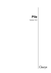
MLS 608 D SA Application Diagram
CH
Extron
MTP T 15HD A D
DIO
IN
TCP/IP
Network
Microphones
003
CH
Help Desk
Monitoring
and Control
003
Ethernet
Transmitter
AU
R IN
TE
MPU
CO
Projector
Control
Tx
L
NT
R
& VC
D
RO
CO
DVD
DV
VCR
TUN
ER
NU
P
STO
ME
ER
SE
ENT
WD
LE
Switcher
Control
TO
AU GE
IMA
Y
LA
SP
DI
R
VC
1
4
2
5
3
6
EW
Y
PLA
NEX
V/R
PRE
PC
MLC
226
IP
DV
+
C
DO
M
CA
F
OF
OP
PT
LA
ON
D
PAU
T/F
TIT
X
AU
EO
VID
DV
IG
NF
CO
ME
LU
IR
VO
Enhanced MediaLink
Controller w/ IP Link
A SA
8MD
D
8 60
60
MLS
MLS
Extron
MLC 226 IP DV+
RT
RS
Tx
N/A
N/A
N/A
N/A
RT
SE
SEIN
IN32
32-2
-2RS
RxTx
Rx
2V
2V+1
+1
R
S
W-20W
SUT
- 40M
UT
TP
V OH
TP
70
OU
4/8
O
OU
O DI
DIAU
L
AU
V
V+ 48 L
L1
R
1
R
L
2
L
2R
x 2 Tx RxTx
Rx
32
32-2
-2RS
ST
RS ST
HO
HO
W
W7.2
T=
= 7.2
TOU
R
OU
RPW
R
PW
+ 48
TS L
TS
PU
PUIN
INO
O DI 2 R
DIAU 2 R
AU L L
L
UT
UT
TP
TP
OU
OUL
LTA
2
TAGI
2
GIDI
DI
6
Extron
MLS 608 D SA
Hz
/60
/6050
Hz
1
TS
TS
PU
PUIN
IN
OG
OG
AL
AL
AN
AN
LE
LE
AB
AB
UT
UR
UT
IG
TP
UR
IGNF
TP
OU
NF
OU
CO
ED
CO
ED
ER
ER
FF
FF
BU
BU
1
3
3
7
5
8
Screen
Control
7 R
7 R
L
6 R
6 R
L
5 R
5 R
L
2
8
2 -23
-23
+ RS
VID
Digital Video +
RS-232
7
T
+12
1
2
6
RS
+ EO
EO
VID
5
INE 2 1
INE 2
MIC/L
MIC/L
1
2
1
8 R
8 R
L
1
1
TS
TS
PU
PUIN
INL
LTA
TAGI
GIDI
DI
UT
UT
TP
TP
OU
OU
OG P P
MT
OG
AL
MT +
AL
AN
AN
+ DIO
O
DIAU
AU
L
L
L
3 R
3 R
L
L
1 R
1 R
L
T V OU
+12
V OU
Extron
SI 3
T=
OU
T=R OU
) PWR12WPW12W
) TP
TP
4 (M
4 (M
50
V
V 40
400-2
0-210
-232
10
2
RS
2
MTP + Audio
X MA
MAA
A 3.2
E
AR
SP
Tx
Rx
NO
O
DI
AU 2
MO
1
VID
X
Y
3.2
B-
S
UT
TP
OU
C
Y/
Y
L OU
TA
SS
PA
T
PU
MI
HD
2
1
OG
AL
AN
Surface Mount
Speakers
Receiver
T
2
-23 RU
RS TH
L IN
TA
DIGI
RG
R-
TP
DIGI
B
Y
UT
Extron
MTP/HDMI U R
Tx
Rx
PU
MTP
IN
Projector
Control
R
WE
PO
X
V
12 A MA
0.8
PC
HDMI + Audio
Projector
HDMI + Audio
Document
Camera
Laptop
Blu-ray
Player
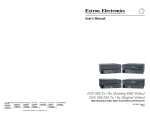
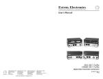
Figure 1. MLS 608 D SA and MTP/HDMI U R, with an Optional MLC 226 IP DV+
MLS 608 D Series • Introduction
4
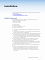
Installation
This section contains installation information for an MLS 608 D Series device and covers
the following subjects:
zz
UL/Safety Requirements
zz
Mounting the MLS 608 D Series Switcher
UL/Safety Requirements
The Underwriters Laboratories (UL) requirements listed below pertain to the safe
installation and operation of this AV Switcher.
1. Read these instructions.
2. Keep these instructions.
3. Heed all warnings.
4. Follow all instructions.
5. Do not use this apparatus near water.
6. Clean only with a dry cloth.
7. Do not block any ventilation openings. Install in accordance with the manufacturer’s
instructions.
8. Do not install near any heat sources such as radiators, heat registers, stoves, or other
apparatus (including amplifiers) that produce heat.
9. Do not defeat the safety purpose of the polarized or grounding type plug. A polarized
plug has two blades with one wider than the other. A grounding type plug has two
blades and a third grounding prong. The wide blade or the third prong are provided
for your safety. If the provided plug does not fit into your outlet, consult an electrician
for replacement of the obsolete outlet.
10. Protect the power cord from being walked on or pinched particularly at plugs,
convenience receptacles, and the point where they exit from the apparatus.
11. Only use attachments/accessories specified by the manufacturer.
12. Use only with the cart, stand, tripod, bracket, or table specified by the manufacturer,
or sold with the apparatus. When a cart is used, use caution when moving the cart/
apparatus combination to avoid injury from tip-over.
13. Unplug this apparatus during lightning storms or when unused for long periods of
time.
14. Refer all servicing to qualified service personnel. Servicing is required when the
apparatus has been damaged in any way, such as power-supply cord or plug is
damaged, liquid has been spilled or objects have fallen into the apparatus, the
apparatus has been exposed to rain or moisture, does not operate normally, or has
been dropped.
MLS 608 D Series • Installation
5
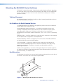
Mounting the MLS 608 D Series Switchers
If the device is to be rack mounted, it may be easier to do so before cabling it, depending
on the ease of access to the rear panel after mounting. Four rubber feet are included with
the unit. Install the feet only if the unit is to be mounted on a tabletop (see “Tabletop
placement” below).
Tabletop Placement
For tabletop placement, install the self-adhesive rubber feet/pads (provided) onto the four
corners of the bottom of the device.
UL Guidelines for Rack Mounted Devices
The following Underwriters Laboratories (UL) guidelines pertain to the safe installation of
the MLS 608 D Series switcher in a rack.
Elevated operating ambient temperature — If installed in a closed or multi-unit rack
assembly, the operating ambient temperature of the rack environment may be greater
than room ambient temperature. Therefore, install the device in an environment
compatible with the maximum ambient temperature (Tma = +122 °F, +50 °C) specified by
Extron.
Reduced air flow — Install the equipment in a rack so that the amount of air flow required
for safe operation of the equipment is not compromised.
Mechanical loading — Mount the equipment in the rack so that a hazardous condition is
not achieved due to uneven mechanical loading.
Circuit overloading — Connect the equipment to the supply circuit and consider the
effect that circuit overloading might have on overcurrent protection and supply wiring.
Appropriate consideration of equipment nameplate ratings should be used when
addressing this concern.
Reliable earthing (grounding) — Maintain reliable grounding of rack-mounted equipment.
Pay particular attention to supply connections other than direct connections to the branch
circuit (for example, use of power strips).
Rack Mounting
To rack mount the switcher, insert screws into the brackets and attach them to the sides of
the switcher. Then secure it to the the rack (see figure below).
2U Rack Mount
Bracket (use four
lower holes)
Figure 2. Mounting the MLS 608 D Series Switcher
MLS 608 D Series • Installation
6
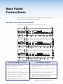
Rear Panel
Connections
This section describes the rear panel features and how to connect the cables to the
MLS 608 D and to the MTP/HDMI U R as applicable.
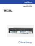
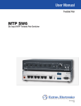
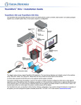
MLS 608 D Series Rear Panel Features
This illustration shows all possible features of the MLS 608 D Series.
3
MLS 608 D SA
6
14
MLS 608 D SA
50/60 Hz
CONFIGURABLE ANALOG INPUTS
1
DIGITAL INPUTS
ANALOG OUTPUT
MTP
+
AUDIO
L 1
1
BUFFERED OUTPUT
2
3
+12 V OUT
L 2
L 3
R
Tx Rx
R
AUDIO OUTPUTS
2
L 5
8
7
RS-232 INSERT
AUDIO INPUTS
R
DIGITAL OUTPUT
6
5
N/A
N/A
100-240V
L 6
R
L 7
R
L 8
R
MIC/LINE
1
2
R
4/8 OHM - 20W x 2
+ 48V
L
1
R
2
L
+12V
R
Tx Rx
1
2
4 (MTP)
RS-232
HOST
VIDEO + RS-232
PWR OUT=
12W
1.2A MAX
PWR OUT = 7.2W
1
2
4
3
MLS 608 D MA
7
5
8
9
10
12a
11
13
14
6
MLS 608 D MA
50/60 Hz
CONFIGURABLE ANALOG INPUTS
1
DIGITAL INPUTS
ANALOG OUTPUT
MTP
MTP
+
+
AUDIO
AUDIO
L 1
6
5
11
BUFFERED OUTPUT
2
3
+12 V OUT
7
RS-232 INSERT
AUDIO INPUTS
R
L 2
L 3
R
Tx Rx
R
DIGITAL OUTPUT
AUDIO OUTPUTS
22
L 5
8
N/A
N/A
100-240V
L 6
R
L 7
R
L 8
R
R
MIC/LINE
1
2
+ 48V
70V - 40W
L
1
R
L
2
R
+12V
Tx Rx
1
2
4 (MTP)
PWR OUT=
12W
1.2A MAX
RS-232
HOST
VIDEO + RS-232
PWR OUT = 7.2W
1
2
4
3
MLS 608 D
8
7
5
9
10
12b
11
13
14
6
MLS 608 D
50/60 Hz
CONFIGURABLE ANALOG INPUTS
1
DIGITAL INPUTS
ANALOG OUTPUT
MTP
+
AUDIO
5
L 1
6
1
BUFFERED OUTPUT
2
3
+12 V OUT
L 2
R
RS-232 INSERT
L 3
Tx Rx
R
AUDIO OUTPUTS
2
L 5
8
7
AUDIO INPUTS
R
DIGITAL OUTPUT
N/A
N/A
100-240V
R
L
6
L 7
R
R
L 8
R
MIC/LINE
1
2
+ 48V
L
1
R
L
2
+12V
R
Tx Rx
1
2
4 (MTP)
RS-232
HOST
VIDEO + RS-232
PWR OUT=
12W
1.0A MAX
PWR OUT = 7.2W
1
2
4
5
7
8
9
10
11
13
Figure 3. MLS 608 D Series Rear Panel Features
Power, analog, and digital connections
a
b
AC power connector
c
Audio and RS-232 connections
i
j
Audio inputs, 5-pole captive screw connectors, (inputs 1-3, 5-8)
Buffered output, VGA connector (tied only to input 1)
k
Line level audio output, 5-pole captive screw connectors, (audio
outputs 1-2)
d
e
f
Universal MTP RJ-45 connector (input 4)
Power amplifier output connector 4/8 ohm, 20 x 2 W (SA model)
Analog video and audio MTP output, RJ-45 connector
£
§
m
g
h
Digital inputs, HDMI connectors (inputs 5-8)
n
RS-232 insertion port, 5-pole captive screw connector
RGB, component/S-video/composite inputs,
VGA connectors, (inputs 1-3)
2-pole power output connector, optional MTP power source
Mic/Line level audio inputs (1-2), 3-pole captive screw connectors
and phantom power LEDs
Power amplifier output connector 70 V, 40 W (MA model)
RS-232 control/configuration port and +12 V power out (for optional
MLC power source), 5-pole captive screw connector
Digital video and RS-232 outputs, RJ-45 connectors
MLS 608 D Series • Rear Panel Connections
7
Power, Analog, and Digital Connections
a Power input — Connect the standard IEC power cord from a 100 to 240 VAC, 50 Hz
or 60 Hz power source into this connector. The front panel control and input selection
buttons light in sequence during power-up.
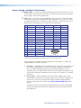
b Inputs 1-3 — These three universal analog input ports (15-pin HD [VGA] connectors)
can be configured to accept RGB (RGBHV, RGBs), component (bi- or tri-level), S-video,
or composite video signals. The default setting is for RGB. The table below shows the
pinouts for each format type on the 15-pin HD (VGA) connector.
Pin
RGBHV
RGBs
Component
S-video
1
Red
Red
R-Y
Chroma
2
Green
Green
Y
Luma
3
Blue
Blue
B-Y
4
ID Bit
ID Bit
5
N/C
N/C
Composite
Video
6
Red Return
Red Return
R-Y Return
C Return
7
Green Return
Green Return
Y Return
L Return
8
Blue Return
Blue Return
B-Y Return
10
Ground
Ground
11
ID Bit
ID Bit
Video Return
9
12
ID Bit
ID Bit
13
H Sync
C Sync
14
V Sync
15
ID Bit
ID Bit
10
5
1
6
15
11
HD15 Pin Locations
Female
Plug in up to three video input sources into these VGA connectors.
From these ports, the signals are passed through to the MPT output. The ports also
support RGB delay and EDID emulation.
zz
RGB delay — RGB delay mutes the video first, then switches the sync signals, and
then switches the RGB video. This brief delay allows the display to adjust to the
new sync signal before displaying the picture, providing a glitch-free switch.
The delay can be set using SIS commands or the DSP Configurator software using
the Video I/O workspace. RGB delay can be set from 0 to 5 seconds in 0.5-second
increments.
zz
EDID settings — EDIDs (resolution and refresh rates) for digital inputs can be
automatically assigned when connecting a display with a common resolution and
refresh rate. The user can assign a different EDID, for both analog and digital
inputs, using the data from an EDID table. See the table on page 23 for EDID
settings.
The EDID can be manually assigned using SIS commands or via DSP Configurator.
The default settings are 720p at 60 Hz for digital inputs, and 1024x768 at 60 Hz
for analog inputs.
MLS 608 D Series • Rear Panel Connections
8
c Buffered output — This buffered analog output is
tied only to input 1 and is a direct pass-through from
any video signal, such as composite, S-video, RGBs,
and YUV, that is present on input 1.
CONFIGURABLE ANALOG INPUTS
1
BUFFERED OUTPUT
Connect a local output to this 15-pin HD (VGA)
connector for a buffered analog output from input 1.
The set signal type is output on the VGA connector,
however, for composite, S-video, RGBs, and YUV signals, break out cables are needed
when connecting a display.
d Input 4 — This port is used to input universal MTP video signals with mono audio
support from an MTP transmitter. The input accepts composite, S-video, component
(bi-level and tri-level), and RGB (RGBHV and RGBS) video signals, but does not support
EDID emulation. When switching to this input, the incoming signal is passed to the
MTP output. The MTP HDMI U R receiver auto-detects the incoming video signal and
outputs it on the appropriate video connector.
The input supports level and peaking adjustment, setting the incoming signal to
appropriate levels.
Skew adjustment is available with this input, compensating for up to 64 nanoseconds
of skew. Adjustments are made using DSP Configurator software or SIS commands.
Settings are stored in the memory and recalled when the input is selected.
NOTE: • See the DSP Configurator Help File "Video Settings" section, or the
"SIS Programming and Control" section for method of skew adjustment.
• This port does not accept RS-232 commands from an MTP transmitter.
Connect to the transmitter by plugging a terminated CAT 5, 5e, or CAT 6 twisted pair
cable into these RJ-45 connectors. The T568A and T568B standard pinouts are shown
below. Use the same standard at both ends of the cable.
Pin
T568A Wire Color
T568B Wire Color
Composite
S-video
Component
RGBHV
1
White-green
White-orange
Reserved
Chroma +
R-Y +
Red/V. Sync +
2
Green
Orange
Reserved
Chroma -
R-Y -
Red/V. Sync -
3
White-orange
White-green
Mono Audio +
Mono Audio +
Mono Audio +
Mono Audio +
4
Blue
Blue
Video +
Luma +
Y+
Green +
5
White-blue
White-blue
Video -
Luma -
Y-
Green -
6
Orange
Green
Mono Audio -
Mono Audio -
Mono Audio -
Mono Audio -
7
White-brown
White-brown
Reserved
Reserved
B-Y +
Blue/H. Sync +
8
Brown
Brown
Reserved
Reserved
B-Y -
Blue/H. Sync -
Pins:
12345678
Insert Twisted
Pair Wires
RJ-45
Connector
CAUTION: Do not connect the MTP cable to any LAN port, telecommunications
network, or digital video output port.
Do not connect a LAN cable to any MTP or digital video output port.
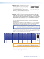
The MLS-to-MTP input and output transmission distances for CAT 5, 5e, CAT 6, and
CAT 7 cable vary depending on the signal type, resolution and the quality of cable
used. See the table on page 10 for distances.
MLS 608 D Series • Rear Panel Connections
9
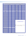
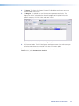
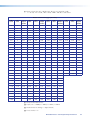
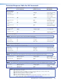
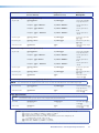
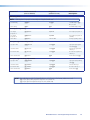
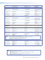
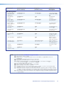
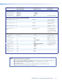
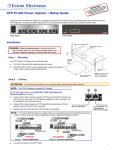
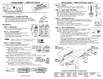
MLS 608 D Analog Signal Transmission Distance Table for Inputs and Outputs, in Feet and (Meters)
NOTE: • The maximum transmission distances are determined by the frequency and resolution of the video signal being
routed. The table below specifies the recommended maximum distances when using Extron Enhanced Skew
Free AV UTP cable or UTP CAT 5, 5e, or CAT 6 cable, terminated with RJ-45 connectors.
• The minimum TP cable length should be 25 feet from the MTP Tx to input 4.
• It is possible to exceed the recommended distances; however, image quality may be reduced.
MLS Pre-Peak
Video Format
Off
On
Component,
S-video
<300 (90)
Composite
Maximum Distance
High Quality
Variable Quality
MLS Input
MLS Output
MLS Input
MLS Output
>350 (105)
700 (215)
700 (215)
700 (215)
800 (245)
<300 (90)
>350 (105)
700 (215)
700 (215)
750 (230)
750 (230)
640x480
<300 (90)
>350 (105)
550 (170)
600 (185)
600 (185)
650 (200)
800x600
<300 (90)
>350 (105)
500 (150)
500 (150)
600 (185)
600 (185)
1024x768*
<300 (90)
>350 (105)
450 (135)
450 (135)
550 (170)
550 (170)
1280x960*
<300 (90)
<350 (105)
350 (105)
350 (105)
450 (135)
450 (135)
1280x1024*
<250 (75)
>300 (90)
350 (105)
350 (105)
450 (135)
450 (135)
1360x765
<250 (75)
>300 (90)
350 (105)
350 (105)
500 (150)
500 (150)
1365x768
<250 (75)
>300 (90)
350 (105)
350 (105)
450 (135)
450 (135)
1366x768
<250 (75)
>300 (90)
350 (105)
350 (105)
450 (135)
450 (135)
1440x900
<250 (75)
>300 (90)
350 (105)
300 (90)
400 (120)
400 (120)
1400x1050
<250 (75)
>300 (90)
350 (105)
300 (90)
400 (120)
400 (120)
1600x1200
<250 (75)
>300 (90)
300 (90)
300 (90)
450 (135)
450 (135)
1920x1200
<200 (60)
>250 (75)
300 (90)
250 (75)
400 (120)
400 (120)
HDTV 720p
<250 (75)
>300 (90)
400 (120)
400 (120)
500 (150)
500 (150)
HDTV 1080i
<200 (60)
>250 (75)
300 (90)
250 (75)
400 (120)
400 (120)
HDTV 1080p
<200 (60)
>250 (75)
300 (90)
250 (75)
400 (120)
400 (120)
Figure 4. Transmission Distance Table for Analog Signals
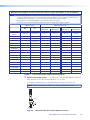
e Optional MTP power output —
This port is for use with an MTP/HDMI U R receiver,
and is rated at 12 VDC with a current draw of 1 A, 12 watts.
This supplies sufficient power via the MLS device to fully power the MTP unit.
NOTE: When the power save mode is set to on, this port also turns off.
Tie Wrap
3
5
Captive Screw
Connector
Figure 5.
Wiring the MLS 608 D Power Output Connector
MLS 608 D Series • Rear Panel Connections
10
f Analog MTP output (audio and video) — This output transmits signals from an
active analog input over CAT 5 cable to the MTP/HDMI U R receiver. It is also capable
of transmitting line level mono audio over the same cable as audio output 3.
The output also supports pre-peaking adjustment for optimizing video signals for long
cable runs.
Skew adjustment is available on this ouput, compensating for up to 64 nanoseconds
of skew. Adjustments are made using DSP Configurator software or SIS commands.
Settings are stored in the memory and recalled when the input is selected.
Connect the MTP HDMI U R twisted pair receiver (supplied) for analog audio and
video output.
NOTES: • See the table on page 9 for pinout details.
• See the table on page 10 for output transmission distances.
g Digital Inputs 5-8 — These four HDMI inputs are HDMI 1.3 compatible and have the
following features:
zz
HDCP authentication – The MLS 608 D gives a status feedback if it detects any
of the following are valid:
zz
If a source is HDCP compliant
zz
If a source has active video
zz
If a display is HDCP compliant (only if connected input is encrypted)
If the source is HDCP compliant but the display is not, the MLS displays a green
screen at the output.
See "HDCP Compliance" within the "DSP Configurator" section, for the detailed
method of HDCP detection and operation.
zz
Digital input equalization — Each digital input has automatic equalization to
compensate for distance from the source to the input. This gives 1080p, 8-bit
color, with a maximum distance of 50 feet using Extron Pro Series HDMI cable.
NOTE: The transmission distance varies greatly depending on the signal
resolution, and on the type of cable, graphics card and display used in
the system.
zz
Audio de-embedding — Each of the HDMI inputs de-embed 2-channel PCM
audio signals at 48 Hz only. Other audio signals are not de-embedded: the signal
will be muted at the DSP processor and audio will not be heard.
The audio to be de-embeded is user selectable from either the existing embedded
digital audio or a local analog input. The default is digital audio.
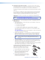
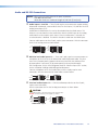
Connect up to four digital HDMI and DVD-D inputs to
the HDMI connectors g. Connect DVI-D sources using an
adapter cable and secure the connectors to the
MLS 608 D using the LockIt™ bracket as follows:
1. Plug the HDMI cable into the panel connection.
2. Loosen the HDMI connection mounting screw
from the panel enough to allow the LockIt
lacing bracket to be placed over it.
3. Place the LockIt lacing bracket on the screw
and against the HDMI connector, then tighten
the screw to secure the bracket.
1
2
3
4
3
MLS 608 D Series • Rear Panel Connections
11
4. Loosely place the included tie wrap around the
HDMI connector and LockIt lacing bracket.
5. While holding the connector securely against the lacing bracket, tighten the tie
wrap, then remove any excess length.
The LockIt bracket can be mounted in different orientations, as shown below.
3
Side Mounted
Top Mounted
Stacked
h Digital video and RS-232 outputs — These two RJ-45 connectors output digital
video signals and RS-232 commands to the MTP/HDMI U R receiver over Extron
STP 201 (recommended), CAT 5, 5e or CAT 6 cable.
The RS-232 signal is bi-directional and its source is tied to the 5-pole, captive screw,
RS-232 Insert port. See the pinout table below. See n (page 16) for the transmission
path.
Pin
T568A Wire Color
T568B Wire Color
RJ-45 #1
RJ-45 #2
1
White-green
White -orange
Data 0 +
CEC
2
Green
Orange
Data 0 -
HPD
3
White-orange
White-green
ID Clock +
Serial +
(RS-232 Insert)
4
Blue
Blue
Data 1 +
DDC Clock
5
White-blue
White-blue
Data 1 -
N/A
6
Orange
Green
ID Clock -
Serial +
(RS-232 Insert)
7
White-brown
White-brown
Data 2 +
DDC Data
8
Brown
Brown
Data 2 -
Ground
NOTE: Terminate both ends of the same cable identically, in accordance with
either the TIA/EIA T568A or TIA/EIA T568B wiring standard.
Plug terminated cable from the MTP HDMI U R in to these two RJ-45 connectors for
digital video and RS-232 output. Using STP201 cable is recommended.
The digital signal transmission distance is shown below.
MLS 608 D to MTP/HDMI U R
Digital Signal Maximum Transmission Distances
8-bit Color Depth
CAT 5/5e/6 Cable
UTP
STP
Resolutions
Extron STP201
Cable
1024x768,
720p, 1080i @ 60 Hz
200' (60 m)
200' (60 m)
200' (60 m)
1600x1200, 1920x1200,
1080p @ 60 Hz
100' (30 m)
125' (38 m)
150' (46 m)
MLS 608 D
SOURCE SELECTION
R
CONFIG
PC
DOC
CAM
1
2
3
VOLUME
AUX
VID
LAPTOP
Blu-ray
4
5
6
7
MIC VOLUME
MTP/HDMI U R
8
AUDIO
RS-232
MLS 608 D
AV Switcher
ANALOG
SIGNAL
VID
Y/C
YUV
RGB
RGB
LEVEL
PEAKING
DIGITAL SIGNAL
MTP/HDMI U R
MLS 608 D Series • Rear Panel Connections
12
NOTES: • Transmission distance varies greatly depending on the signal resolution,
and the type of cable, graphics card and display used in the system.
• Shielded twisted pair cable provides added protection from outside
interference and increases overall signal transmission distance.
Extron recommends using shielded twisted pair for optimal performance.
When using STP cable, terminate the cable as follows:
1. For each cable, peel back the cable shielding from the end of the cable 7/8 inch
[2.2 cm]) and fold it back.
Peel back shield and
fold back.
Figure 6.
Peeling Back the Cable Shielding
2. Cut away and discard the clear cellophane inner wrapper from the end of the
cable back to the folded-over cable shielding.
3. Peel the backing off the self-adhesive shielded aluminum tape and wrap it around
the folded-over cable shielding, slightly overlapping the beginning of the tape.
Aluminum Tape
Figure 7.
Wrap tape around folded foil shielding with a slight overlap.
Cut and save the excess tape for other connectors.
Wrapping the Shielded Tape
4. Cut the unused portion of the shielded tape and retain for further uses.
5. Feed each individual wire into the appropriate slot of the RJ-45 connector and
crimp the cable in the normal manner, folding the tangs at the end of the
connector over the shielded tape.
Crimped Connector
Figure 8.
Crimped RJ-45 Connector
MLS 608 D Series • Rear Panel Connections
13
Audio and RS-232 Connections
NOTES: When wiring the connectors for the ports listed below:
• DO NOT tin the wires.
• Bare the wires to a maximum length of 3/16 inch (5 mm) only.
i Audio inputs 1-3 and 5-8 — These 5-pole captive screw connectors support analog,
balanced or unbalanced, stereo audio as three line level inputs (1-3) and four line level
analog stereo inputs (5-8).
Audio from the HDMI inputs 5-8 can be de-embeded from the HDMI source. This
allows the user to choose to select audio either from the HDMI inputs or the analog
audio from these four captive screw inputs. Once an audio source is selected, the
unselected source is disabled. The default selection is audio from the HDMI inputs.
Connect audio sources to these 5-pole, captive screw connectors. Wire the connector
for line level analog stereo as shown below.
Tip
Ring
Sleeve (s)
Tip
Ring
R
Tip
Sleeve
L
Tip
Sleeve
Balanced Input
Unbalanced Input
j MIC/Line level audio inputs 1-2 — These two 3-pole, captive screw connectors are
microphone or line level inputs for balanced or unbalanced mono audio. They also
have +48 V phantom power support and two rear panel LEDs that indicate when
phantom power is activated. The phantom power can be activated through
DSP Configurator. See the DSP Configurator Help File "Mic/Line Input Gain" section,
for the method of enabling and disabling phantom power.
Connect microphone or line level audio inputs to these 3-pole, captive screw
connectors. Wire the connector for mono audio as shown below.
Tip
Tip
Ring
Sleeve
Sleeve
Unbalanced Mic Input
Balanced Mic Input
k Line level audio outputs 1-2 — Connect audio output devices to these 5-pole,
captive screw connectors.
Wire the connectors for line level analog stereo output as shown below.
CAUTION
For unbalanced audio, connect the sleeve(s) to the ground contact.
DO NOT connect the sleeve(s) to the negative (-) contacts.
Unbalanced Output
Tip
Ring
Sleeve(s)
Tip
Ring
AUDIO
L
R
AUDIO
L
R
Tip
NO Ground Here
Sleeve(s)
Tip
NO Ground Here
Balanced Output
MLS 608 D Series • Rear Panel Connections
14
£ Power amplifier output (MLS 608 D SA) — This
12a
L
model has a 2x20 watt stereo power amplifier
Connect a suitable audio device for 2-channel stereo,
20 watts per channel, 4 or 8 ohm audio output.
Wire the connector as shown at right
R
To 4/8 Ohm
Speaker Load
5 mm
Captive Screw
§ Power amplifier output (MLS 608 D MA) — This
model has a 40 watt, 70 volt, mono power amplifier.
Connect a suitable audio device for mono audio,
40 watts, 70 volt audio output.
Wire the connector as shown at right.
NC
12b
NC
To 70 V Speaker
5 mm
Captive Screw
NOTE: The MLS 608 D model has a variable preamp output with no power
amplifier.
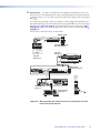
m RS-232 control and +12 VDC power output — This port is used for configuration
and control of the MLS 608 via RS-232, and for powering the control device (such as
an optional MLC 226).
NOTE: The RS-232 control and +12 VDC power output port is always active,
regardless of the power save mode status.
RS-232 configuration — To configure the MLS 608, connect this 5-pin connector to
a PC or laptop that has DSP Configurator software installed on it.
Control via RS-232 — To control the MLS 608 via RS-232 after configuration is
complete, disconnect the PC or laptop and connect a MediaLink control system (such
as an MLC 226) to the RS-232 host port.
Default protocol: 38400 baud, 1 stop bit, 8 data bits, no flow control.
Wire the MLC to the MLS 608 as shown below.
RS-232
Host
CONFIGURABLE ANALOG INPUTS
1
DIGITAL INPUTS
ANALOG OUTPUT
MTP
+
AUDIO
L 1
5
6
3
7
8
1
+12 V OUT
L 2
R
RS-232 INSERT
L 3
Tx Rx
R
DIGITAL OUTPUT
BUFFERED OUTPUT
2
AUDIO INPUTS
R
N/A
N/A
50/60 Hz
AUDIO OUTPUTS
2
L 5
R
L 6
R
L 7
L 8
R
R
MIC/LINE
1
2
+ 48V
4/8 OHM - 20W x 2
L
1
R
L
2
R
+12V
Tx Rx
1
2
4 (MTP)
RS-232
HOST
VIDEO + RS-232
PWR OUT=
12W
3.2A MAX
PWR OUT = 7.2W
RS-232/IR
NOTE: You must connect a ground
CM/IR/SCP
NORMALLY OPEN
A
B
C
IR/SERIAL OUT
A B
MLS
+12V IN
5 6
C
Tx/IR
GROUND
B
RELAYS
Rx
Tx
GROUND
GROUND
3 4
COMMON
COMMON
1 2
A
Tx/IR
GROUND
A B C D E
COMMON
IR IN
SCP COM
A B C D E
Tx/IR
GROUND
DISPLAY
+12V OUT
GROUND
CONT MOD
T x / IR
Rx
G RO U ND
MLS 608 D SA
Rear Panel
G RO U ND
+ 12V O U T
MLS 608 D
rear panel
RS-232 Host
port
P WR S N S
Tx Rx
MLS 608 D SA
100-240V
PWR
RS-232 12V
MLC 226 IP
Bottom Panel
wire between the MLC and MLS.
+12 VDC input
MLS
+12V IN
Tx
A B
GROUND
NOTE: If you use cable that has
a drain wire, tie the drain wire
to ground at both ends.
Rx
Transmit (Tx) B
Receive (Rx) A
GROUND
Ground ( )
Ground ( )
B Receive (Rx)
A Transmit (Tx)
MLC's
MLS and
Power
ports
PWR
RS-232 12V
Figure 9.
Wiring the MLS 608 D RS-232 Host Port to an MLC 226 IP
MLS 608 D Series • Rear Panel Connections
15
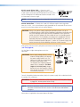
n RS-232 Insert — This port is used to connect an optional control device (such as an
MLC 226 IP or IP Link controller) to this port for bi-directional RS-232 communication
to a display device. This insert port is tied to the MLS 608 D digital and RS 232 output
ports, h.
The transmission pathway is from, for example, an MLC 226 IP bi-directional RS-232
port (labelled Display) to the MLS 608 D RS-232 Insert port n, out via the MLS 608 D
digital outputs (see h on page 12) to the MTP/HDMI U receiver input port (see
on page 17) and then out to the display device via the receiver's RS-232 port (see
on page 17).
Wire the MLC to the MLS 608 as shown below.
RS-232 Insert
Tx Rx
Transmit (Tx)
Receive (Rx)
Ground ( )
N/A
N/A
Tx/IR
Rx
GROUND
PWR SNS
GROUND
+12V OUT
MLS 608 D rear panel
RS-232 Insert port
CM/IR/SCP
RS-232/IR
NORMALLY OPEN
B
C
IR/SERIAL OUT
A B
MLS
GROUND
+12V IN
A
Rx
Tx
GROUND
Tx/IR
GROUND
5 6
C
Tx/IR
GROUND
3 4
B
RELAYS
Tx/IR
GROUND
1 2
A
COMMON
A B C D E
COMMON
A B C D E
DISPLAY
COMMON
IR IN
SCP COM
MLC 226
Display port
T x /IR
Rx
GROU N D
PWR SN S
GROU N D
+1 2 V OU T
RS-232/IR
+12V OUT
GROUND
CONT MOD
MLC 226
Display port
DISPLAY
PWR
RS-232 12V
RS-232
MLS 608 D SA
50/60 Hz
CONFIGURABLE ANALOG INPUTS
DIGITAL INPUTS
ANALOG OUTPUT
1
MTP
+
AUDIO
5
L 1
3
1
+12 V OUT
7
L 2
R
RS-232 INSERT
L 3
Tx Rx
R
DIGITAL OUTPUT
6
BUFFERED OUTPUT
2
AUDIO INPUTS
R
N/A
N/A
100-240V
AUDIO OUTPUTS
2
L 5
8
L 6
R
R
L 7
R
L 8
R
MIC/LINE
1
2
+ 48V
4/8 OHM - 20W x 2
L
1
R
L
2
R
MLS 608 D
RS-232 Insert port
+12V
Tx Rx
1
2
4 (MTP)
RS-232
HOST
VIDEO + RS-232
PWR OUT=
12W
3.2A MAX
PWR OUT = 7.2W
RS-232
DIGITAL INPUT
1
DIGITAL OUTPUT
RS-232
2
POWER
12V
0.8A MAX
R-Y
HDMI
Y
Tx Rx
B-Y
VID
RS-232
PASS THRU
Tx Rx
MTP INPUT
MTP/HDMI U R
Input port
MTP/HDMI
RS-232
Pass-thru
port
RGB
SPARE
MONO AUDIO
1
2
Tx Rx
Y/C
ANALOG OUTPUTS
RS-232
Display device
RS-232 port
Rx Tx Ground
RS-232
Device pins
Figure 10. Wiring the MLS 608 D RS-232 Insert Port (showing RS-232 Flow
Path to the Display Device)
MLS 608 D Series • Rear Panel Connections
16
MTP/HDMI U R Connections
The full MLS 608 D system comes with an MTP/HDMI U R receiver. To work with any of the
MLS 608 D units, connect the receiver as shown below.
Power input
MTP input
RS-232 port (analog side).
Not used in MLS 608 D system
Digital signal inputs (1 and 2)
RGBHV, RGBS output*
Composite video output*
Digital (HDMI) output
RS-232 pass-through connector
Mono audio output
S-video output*
Component video (R-Y, Y, B-Y)
output*
* = Analog outputs
Digital video inputs — Connect the digital video and RS-232 outputs 1 and 2 from the
MLS 608 D (see h on page 12) using CAT 5, 5e, or 6 twisted pair cabling to the
MTP/HDMI UR receiver inputs 1 and 2 (see above).
Digital video output — Connect a display to the HDMI connector for digital video
output.
Analog video — Connect the analog video outputs , , , and , as shown below:
Component Video –
Connect to these 3 BNCs.
RS-232 Control (Analog Side) –
NOT USED IN THE MLS 608 D SYSTEM.
Composite Video –
Connect to this BNC.
RS-232
Y
Tx Rx
B-Y
VID
RGBHV and RGBS –
Connect to this VGA
connector.
Unbalanced Output
MONO AUDIO
1
2
Y/C
ANALOG OUTPUTS
S-video – Connect to
this mini DIN connector.
Mono Audio – Connect
to this captive screw
connector.
Mono output 1+
Mono output 1Sleeve(s)
Mono output 2+
Mono output 2-
MONO AUDIO
L
R
RGB
SPARE
MONO AUDIO
L
R
R-Y
Mono output 1
NO GROUND.
Sleeve(s)
Mono output 2
NO GROUND.
Do not tin
the wires!
Balanced Output
Wire the audio connector as shown above.
Audio — Connect a suitable audio device, such as powered speakers, to the 5-pole
captive screw audio output connector for a balanced or unbalanced, dual mono audio
signal. Wire connector as shown above.
NOTE: The audio signal is detected on the MTP input and then is distributed to the
audio connector for output.
MLS 608 D Series • Rear Panel Connections
17
RS-232 control (digital side) — Connect a serial
communications port on a display device to the 3.5 mm,
3-pole captive screw connector (labeled RS-232 pass-thru)
for pass-through RS-232 bidirectional communication. Wire
the connector as shown at right.
RS-232 Device Pins
Rx
Tx
Tx
Rx
MTP/HDMI
RS-232
Pass-thru
port
Ground
NOTE: RS-232 control port on the analog side is not used in the MLS 608 D system.
Power connection — Connect the 2-pole 3.5 millimeter captive screw connector
from the 12 VDC, 1.0 A external power supply (provided) to this receptacle on the rear
panel. Ensure the connections have the correct polarity.
CAUTION: Always use a power supply supplied or specified by Extron. Use of an
unauthorized power supply voids all regulatory compliance certification and
may cause damage to the supply and the end product. Unless otherwise
stated, the AC/DC adapters are not suitable for use in air handling spaces
or in wall cavities. The installation must always be in accordance with the
applicable provisions of National Electrical Code ANSI/NFPA 70, article 75
and the Canadian Electrical Code part 1, section 16. The power supply shall
not be permanently fixed to building structure or similar structure.
Alternatively, connect to the 2-pole power connector on the MLS 608 D
(see e on page 10).
See the figure at right showing how to wire the
connector.
CAUTIONS: Power supply voltage polarity is critical.
Incorrect voltage polarity can damage
the power supply and the unit. The
ridges on the side of the cord identify
the power cord negative lead.
The length of the exposed (stripped)
copper wires is important. The ideal
length is 3/16 inch (5 mm). Longer
bared wires can short together. Shorter
wires are not as secure in the connectors
and could be pulled out.
Smooth
Ridges
A
A
2-pole Captive
Screw
Connector
Tie Wrap
Power Supply
Output Cord
3
SECTION A–A
To verify the polarity before connection, plug in the power supply with no load and check
the output with a voltmeter.
WARNING: The two power cord wires must be kept separate while the power supply
is plugged in. Remove power before wiring.
NOTE: Do not tin the power supply leads before installing them in the direct insertion
connector. Tinned wires are not as secure in the connectors and could be
pulled out.
When power is applied the front panel power LED lights.
MLS 608 D Series • Rear Panel Connections
18
Power Save Mode
Power Save mode is a feature on the MLS 608 D that will help conserve energy and reduce
costs by placing the unit into a standby state. The switcher does not have an auto-power
down feature (like the one used on the XPA 1002, for example), and can only be placed
into the standby state via an SIS command. Sending the SIS command E1PSAV] turns
on the power save mode.
When Power Save mode is enabled the switcher draws less than 4 watts, the front panel
buttons and volume indicators are off, and the front panel power LED is amber, indicating
that the switcher is in the standby state.
The switcher can be “woken” up with an SIS command (E0PSAV]), or by pressing any
front panel button or turning any encoder/knob. This reverts the switcher to the normal
mode (power save off).
When in its normal state, the front panel buttons and volume indicators are lit and the
power LED indicator is green.
NOTES: • If the switcher is in the standby state, and power is re-cycled on the unit,
it powers back up into the normal state, and not into the standby state.
• The switcher is not ENERGY STAR® qualified.
MLS 608 D Series • Rear Panel Connections
19
Operation
This section of the manual discusses the operation of an MLS 608 D device, and is divided
into four sections:
zz
Front Panel Features and Operation
zz
Using EDIDs
zz
Optimizing Audio — An Overview
zz
Optimizing Video — An Overview
zz
Firmware Upgrades
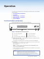
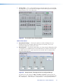
Front Panel Features and Operation
All MLS 608D models have the same front panel configuration.
SOURCE SELECTION
R
CONFIG
PC
DOC
CAM
1
2
3
VOLUME
AUX
VID
LAPTOP
Blu-ray
4
5
6
7
MIC VOLUME
8
MLS 608 D
AV Switcher with ProDSP™
1
2
5
4
3
6
Figure 11.MLS 608D Device Front Panel Features
a
Power and reset status LED
d
Source selection buttons
b
c
Reset button
e
f
Volume control knob
Front panel mini USB configuration port
Mic volume control knob
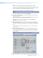
a Power/reset status LED — This LED lights green when power is applied, and amber
when in power save (standby) mode.
It also indicates reset mode when the reset button is pressed (see method below).
b Reset button — Press and hold this recessed button to reset the MLS switcher to one
of the two available reset mode: modes 1 and 5.
Reset as follows:
Mode 1 — Revert to factory firmware version where incompatibility issues
occur with user loaded firmware.
To reset temporarily to the factory default firmware, press and hold in the reset button
while applying power to the unit.
NOTES: • After a Mode 1 reset, update the firmware to the latest version.
DO NOT use the factory firmware resulting from the reset.
Factory firmware must be re-uploaded if that is the version to be used.
• If you do not want to update the firmware, recycling the power reinstates the
firmware version used before the Mode 1 reset.
MLS 608 D Series • Operation
20
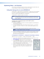
Mode 5 — Reset the MLS 608 D to factory default (except firmware).
To reset the device to factory defaults (with the exception of the firmware), press and
hold in the reset button for approximately 9 seconds, until the LED blinks three times
(once at 3 seconds, once at 6 seconds, and once again at 9 seconds).
Release and within 1 second press the reset button once (<1 second).
NOTES: Nothing will happen if the momentary press is not made within 1 second.
This reset is equivalent to the SIS reset command EZQQQ.
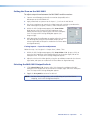
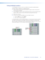
c Front panel configuration port — This port is used for MLS 608 D configuration
and firmware upgrades.
Connect a computer to this mini USB port (cable not supplied) for configuration and
control using DSP Configurator software or SIS commands.
For firmware upgrades use the Firmware Loader Software. See "Firmware
Upgrades" later in this chapter for method.
d Source selection buttons — These eight buttons are used to select between any
of the eight inputs. The button lights amber when selected, and can be configured
to show an input number, icon, or device name as desired using the supplied button
labels.
Alternatively, these buttons can be labeled as required. See the “Button Labeling”
section for details.
e Program volume adjustment knob — This knob is assigned to Group Master 1,
which controls program outputs 1, 3, and 4 (MA and SA models only), post switcher,
pre-mic mixing programs. By default it controls the volume of the three program
outputs together.
NOTE: By default, program output 2 has a fixed output level.
Group Master 1
Group Master 2
Figure 12.Group Masters 1 and 2 Assigned to Front Panel Adjustment Knobs
MLS 608 D Series • Operation
21
Use this volume adjustment knob to set or adjust the program output volume
(attenuation, from -100 dB to 0 dB) as desired. The LEDs indicate the overall
percentage level for Group Master 1; the volume level being all off (0%) at -100 dB
through to all on (100%) at -4 to 0 dB. Any level changes made do not affect the mic
audio.
Rotate the knob clockwise to increase volume,
counter-clockwise to decrease volume. The
corresponding LEDS light as the knob is rotated.
See the table at right for LED/dB values.
VOLUME
LED equivalent
dB value
-4 to 0
-9 to -5
-14 to -10
-19 to -15
Volume control of Group 1 individual program
outputs (programs 1, 3, or 4) can be made
through DSP Configurator software. Group 1
can be reconfigured through DSP Configurator
software.
-29 to -20
-49 to -30
- 69 to -50
-99.9 to -70
-100 (all LEDs
off)
f Mic volume adjustment
knob — This knob
is assigned to Group Master 2, which controls
the mic inputs at the second gain block, pre-mic
mixer-gain programs (see figure 12). By default it controls both microphones, and
level changes do not affect the program audio.
Use this knob to set or adjust the two MIC volumes as desired from -100 dB to 0 dB.
The LEDs indicate the volume level. See the table at above right for LED/dB values.
Rotate the knob clockwise to increase volume, counter-clockwise to decrease volume.
The corresponding LEDS light as the knob is rotated.
Volume control of Group 2 individual mic levels (mic pre-mixer gains 1 and 2) can be
made through DSP Configurator software.
Group 2 can be reconfigured through DSP Configurator software.
NOTE: The program and mic volume settings and adjustments can also be made
using Extron DSP Configurator program or by Simple Instruction Set (SIS)
commands. See the “Using the DSP Configurator Software”section
and the “SIS Programming and Control” section for details.
Using EDIDs
EDID Minder
This pre-installed feature ensures that all sources power up properly and reliably
output content for display. EDIDs (resolution and refresh rates) for digital inputs can be
automatically assigned when connecting a display with a common resolution and refresh
rate. For both analog and digital, the user can assign a different EDID from an EDID table.
A different EDID (as given in the table on the next page), can be manually assigned using
SIS commands or via DSP Configurator.
For the MLS 608 D units, the default settings are 1024x768 at 60 Hz for analog inputs,
and 720p at 60 Hz, 2-channel PCM audio for digital inputs.
NOTES: • To work with the EDID Minder, update the EDID table, and import or export
EDID data, the MLS 608 D must be connected in Live mode.
MLS 608 D Series • Operation
22
EDID Resolution/Refresh Rate Combination with SIS Variables (where X2! = 1 through 64)*
Digital Signal
Resolution
Refresh Rate (Hz)
Automatic Mode (digital only)
Analog Signal
SIS value for X2!
Resolution
Refresh Rate (Hz)
SIS value for X2!
0
800x600
60
29
800x600
60
1
1024x768 (default)
60
30
1024x768
60
2
1280x768
60
31
1280x768
60
3
1280x800
60
32
1280x800
60
4
1280x1024
60
33
1280x1024
60
5
1360x768
60
34
1360x768
60
6
1366x768
60
35
1366x768
60
7
1440x900
60
36
1440x900
60
8
1400x1050
60
37
1400x1050
60
9
1600x1200
60
38
1600x1200
60
10
1680x1050
60
39
1680x1050
60
11
1920x1200
60
40
1920x1200
60
12
576p
50
41
576p, 2-ch PCM Audio
50
13
480p
60
42
480p, 2-ch PCM Audio
60
14
720p
50
43
576p, Multi-ch Audio
50
15
720p
60
44
480p, Multi-ch Audio
60
16
1080i
50
45
720p, 2-ch PCM Audio
50
17
1080i
60
46
720p, 2-ch PCM Audio (default)
60
18
1080p
50
47
720p, Multi-ch Audio
50
19
1080p
60
48
720p, Multi-ch Audio
60
20
User Loaded #1
49
1080i, 2-ch PCM Audio
50
21
User Loaded #2
50
1080i, 2-ch PCM Audio
60
22
1080i, Multi-ch Audio
50
23
1080i, Multi-ch Audio
60
24
1080p, 2-ch PCM Audio
50
25
1080p, 2-ch PCM Audio
60
26
1080p, Multi-ch Audio
50
27
1080p, Multi-ch Audio
60
28
User Loaded #3
* See the "SIS Programming and Control" section
for full details and use of SIS variables.
51
User Loaded #4
52
800x600, 2-ch PCM Audio
60
53
1024x768, 2-ch PCM Audio
60
54
1280x768, 2-ch PCM Audio
60
55
1280x800, 2-ch PCM Audio
60
56
1280x1024, 2-ch PCM Audio
60
57
1360x768, 2-ch PCM Audio
60
58
1366x768, 2-ch PCM Audio
60
59
1440x900, 2-ch PCM Audio
60
60
1400x1050, 2-ch PCM Audio
60
61
1600x1200, 2-ch PCM Audio
60
62
1680x1050, 2-ch PCM Audio
60
63
1920x1200, 2-ch PCM Audio
60
64
NOTE: EDIDs values 53 though 64 are available only
with firmware 1.03 or higher.
Figure 13.EDID Table with SIS Commands
MLS 608 D Series • Operation
23
Automatic EDID Mode (digital output only)
In this mode, if no displays are connected, the default EDID (720p @ 60 Hz, with
2-channel PCM audio support) is present as the native resolution at each HDMI input.
When a display is connected to the digital output, the EDID of that display is automatically
read and stored, and the default EDID is overwritten for each HDMI input. The reading and
storage of the new data is triggered by the Hot Plug Detect signal (HPD) the moment the
display is detected. The stored data remains present even after the display is removed.
When a display with a different EDID is connected, or a user assigned EDID is chosen, the
HDP triggers a new data overwrite for all the digital inputs.
NOTE: The Hot Plug Detect (HDP) signal triggers on all digital inputs simultaneously
whenever a stored EDID is updated regardless whether it is by an automatic or
user assigned EDID. This allows the source to restart the EDID read and verify
the HDCP authentication process.
User Assigned EDID Mode
In this mode the EDIDs can be chosen (by the user) from the table and can be assigned to
each input group (VGA and HDMI). Within this mode, the user EDID can be factory loaded
(see EDID table on page 22) or user loaded. For user loaded EDIDs these can be either
analog or digital EDIDs.
User Loaded EDID – Analog
The EDID of a display connected to the local (VGA) Buffered Output connector (see c on
page 9) can be read and stored to the analog User Loaded spaces 1 or 2 (SIS values 49
and 50, see figure 14). This analog output EDID can later be recalled as the user assigned
analog EDID for inputs 1through 3.
To save the analog output EDID information to the User 1 or User 2 location in the
EDID table:
1. Connect the display to the local analog output on the MLS 608 D Series switcher.
2. Start DSP Configurator, if it is not running already, and connect to the device in the
Live mode.
3. From the Tools menu, select Configure EDID to open the EDID Configuration
dialog box.
Figure 14.EDID Configuration Dialog Box
4. In the Save Analog Output to User Loaded IDs section, click the User 1 or
User 2 button. This saves the EDID information from the analog output to the
associated location (User 1 or User 2). The saved resolutions and refresh rates are
now available as User 1 and User 2 options in the Inputs 1-3 section.
MLS 608 D Series • Operation
24
User Loaded EDID – Digital
The EDID of a display connected to the HDMI output of the MTP/HDMI U R receiver (see
on page 17) can be read and stored to the digital user loaded spaces 3 or 4 (SIS values
51 and 52, see figure 14). This can be recalled later as the user assigned EDID.
To save the digital output EDID information to the User 3 or User 4 location in the
EDID table:
1. Connect the display to the digital output on the MTP/HDMI U R receiver.
2. Start DSP Configurator, if it is not running already, and connect in the Live mode .
3. From the Tools menu, select Configure EDID to open the EDID Configuration
dialog box (see figure 14).
4. In the Save Digital Output to User Loaded IDs section, click the User 3 or User 4
button. This saves the EDID information from the digital output to the associated
location (User 3 or User 4). The saved resolution and refresh rate are now available as
User 3 and User 4 options in the Inputs 5-8 section.
Importing EDID Data
EDID data files (previously saved as BIN files) can be imported using DSP Configurator
software. This enables the user to use a previously saved file, for example a specific
customized EDID, that has been saved on a PC or laptop. The file is uploaded to one of
the four user loaded spaces, depending on if it is an analog or digital EDID, and then it can
be assigned to the relevant inputs.
To import EDID data to one of the four user loaded spaces:
1. Ensure the PC or laptop has the relevant file on it and is connected to the MLS 608 D.
2. Start DSP Configurator, if it is not running already and connect in the Live mode.
3. From the Tools menu, select Configure EDID to open the EDID Configuration
dialog box (see figure 14).
4. Click the Import button. The import dialog box opens.
5. Select the relevant user loaded button, depending if it is an analog or digital EDID.
6. Browse to where the file (xx.BIN) is located.
7. Select the file and click OK.
Exporting EDID Data
EDID data files can be exported using DSP Configurator software so that the data within
the file can be stored for use on another device, viewed, printed, or examined block by
block for troubleshooting purposes for example, in EDID Manager software.
To export EDID data:
1. From the Tools menu, select Configure EDID. The EDID Configuration dialog box
opens.
2. Click Export EDID. The Export EDID dialog box opens (see figure below).
Figure 15.Export EDID Dialog Box
MLS 608 D Series • Operation
25
3. From the Configuration to export drop-down list, select the desired EDID
configuration to export. This can include EDID information that is stored at one of the
available user-defined locations.
4. Click OK. The Save As dialog box opens.
5. Navigate to the location where the configuration is to be saved.
6. In the File name field, enter a name for the file or leave the original file name.
7. Click Save. EDID Configuration files are saved with a BIN extension.
Updating the EDID Table
The table of default EDID resolutions for your software can be updated so the user has the
most current EDID table. The available resolutions are dependent on the installed firmware
version. To obtain the most current EDID table, ensure that the latest firmware version
is installed on the device. To access the Download Center for information regarding the
latest firmware, visit http://www.extron.com/firmware.
To update the EDID table:
1. From the Tools menu, select Configure EDID. The EDID Configuration dialog box
opens.
2. Click Update EDID Table. The Download Updated EDID Table dialog box opens.
Figure 16.Download Updated EDID Table Dialog Box
3. If using a proxy server, select the Use Proxy Server check box. Then, enter the
proxy server address in the Proxy Server field.
4. Click Download. This checks the Extron website for an updated EDID resolution table
based on the firmware version of the connected device.
zz
If an updated EDID table is available, a dialog box opens, notifying you that the
existing EDID resolution table has been updated successfully.
zz
If the existing EDID table is current, a dialog
box opens confirming this.
zz
If DSP Configurator is unable to check for
updates to the EDID table, a dialog box
opens notifying you that there is an error
in downloading the file.
5. In the dialog box that opens, click OK.
NOTE: The update compares the existing table data with that on file and then
adds any new resolutions and refresh rates to the existing table. It does
not change or delete any user loaded data files that have been added to
the existing table.
Once the table is updated, the new EDIDs can be assigned to the relevant inputs as
desired.
MLS 608 D Series • Operation
26
Optimizing Audio — An Overview
Audio optimization is performed using the DSP Configurator application. The application
provides audio level and DSP processing controls that include audio gain, dynamics,
filtering, delay, ducking, and feedback suppression, essential for setting up and
configuring audio systems.
When configuring an MLS 608 D Series device, DSP Configurator has four workspaces
from which you can configure and view processing blocks, mix-points, and audio and
video ties in the system. DSP Configurator defaults to the Audio & Video I/O workspace
when the application launches. You can access the workspaces using:
zz
View menu — From the View menu, select a workspace shown in the list (Audio &
Video I/O, Audio I/O, or Video I/O, or Console View).
zz
Function keys — Use the <F2> (for Audio & Video I/O workspace), <F3> (Audio I/O
workspace), <F4> (Video I/O workspace), and <F5> (Console View workspace) keys.
zz
Hyperlinks — From the Legend section of the GUI (graphical user interface), click a
workspace hyperlink.
Workspaces
The four workspaces are:
zz
zz
zz
zz
Audio & Video I/O workspace — The following areas are available for
configuration:
zz
Switcher in follow mode
zz
Audio gain, trim, and volume controls
zz
Audio DSP processors
zz
Microphone mixer matrix
zz
Presets (building and saving)
Audio I/O workspace — The following areas are available for configuration:
zz
Switcher in audio breakaway mode
zz
All audio gain, trim, and volume controls
zz
Audio DSP processors
zz
Microphone mixer matrix
zz
Presets (building and saving)
Video I/O workspace — The following areas are available for configuration:
zz
Switcher in video breakaway mode
zz
RGB delay and video mute for computer inputs
zz
MTP input and output control
zz
Format selection and video mute for video inputs
zz
Presets (building and saving - ties only)
Console View workspace — This workspace provides an overview of all input and
output activity. From this view you can access a meter bridge and level controls for
input and output gain points plus the primary mix matrix.
NOTE: See the "Workspaces Overview" section in the MLS 608 D Series book in the
DSP Configurator Help File, for more information about these workspaces.
MLS 608 D Series • Operation
27
DSP Signal Chain
The DSP signal chain is in a fixed order and each processor block inserts only one category
of processor. However, the signal chain is also flexible in that a variety of processor types
can be inserted per processor category.
Processor blocks are placed in the signal chain pre- and post-switcher to perform specific
tasks. There are level control blocks, signal processor blocks, and mix-point blocks (with
level control).
Processor blocks
Processor blocks, though performing different functions, have several common elements.
zz
Insert — All blocks (except level controls) may be inserted by right-clicking on the
desired box and selecting from the context menu or by double-clicking and selecting.
zz
Remove a process — Active processors can be removed by right‑clicking on the
box and selecting Delete or by selecting the block and pressing <Delete> on the
keyboard. An active processor may be replaced by right-clicking and inserting a new
processor. A warning will appear to indicate the previous processor is about to be
replaced.
zz
Mute — When a level block (gain, trim or volume) is muted, all signal flow is blocked.
When mute is active a red mark appears in the lower left of the block. Mix-point mute
is indicated by shadowing the mix-point.
zz
Bypass — When bypass is active, signal flow passes through the block without
processing, regardless of the settings. When bypass is removed, the signal will be
processed according to the parameter settings. A red mark appears in the lower left of
the block (shown below) to indicate it has been inserted, but is currently bypassed.
Line input processor blocks
1
2
3
4
5
6
Pre-switcher input signal chain elements shown above, from left to right, are as follows:
a Gain, b Filter, c Dynamics (1), d Dynamics (2), e Delay, f Trim
a Gain (GAIN) — Each line input channel GAIN block opens a Stereo Line Gain dialog,
with the exception of input 4, which opens a Mono Line Gain dialog. The Stereo Line Gain
dialog provides stereo left-channel and right-channel faders. The Mono Line Gain dialog
provides a mono fader. Each fader control has a range of -18 dB to +24 dB and a level
setting text field is located below the fader.
Left-channel and right-channel Mute buttons independently mute the left and right
channels to the stereo bus. As a mono channel, the input 4 Mono Line Gain dialog has a
single Mute button.
NOTE: • Inputs 1 through 4 are analog (ANG GAIN block).
• Inputs 5 through 8 are digital (DIG GAIN block) but can be configured to
accept either a digital (default) or an analog 2-channel input stream.
• Input 4 is a mono input.
MLS 608 D Series • Operation
28
b Filter (FILT) — Up to three frequency filters can be inserted in any combination of High
Pass, Low Pass, Bass & Treble filters, or Parametric Equalizer.
c Dynamics 1 (DYN) — Dynamics processors vary the dynamic level, (the range of
loudest to softest signals). Choices include AGC, compressor, limiter, or noise gate.
d Dynamics 2 (DYN) — A second dynamics processor can be inserted from a choice of
AGC, compressor, limiter, or noise gate.
e Delay (DLY) — Delay can be set either by time or distance. Distance can be expressed
in either feet or meters. The default setting is delay by time, at 100.0 ms. When Feet or
Meters is selected, the Temperature field is enabled and can be set to either Celsius
or Fahrenheit.
f Trim (TRIM) — Each input channel trim block provides left-channel and right-channel
faders or a mono fader (for input channel 4). Each fader has a gain range of -12 dB to
+12 dB and the default setting is unity gain (0.0 dB).
Output processor blocks
1
2
3
4
5
6
7
8
Post-switcher output signal chain elements shown above, from left to right, are as follows:
a Post gain, b Loudness, c Bass and Treble, d Mix-point gain, e Delay, f Filter,
g Dynamics, h Volume
a Post Gain (POST GAIN) — An output channel post gain block provides gain control,
mute control, and the ability to sum the stereo signal to mono.
The default setting for all channels is unity gain (0.0 dB), with the exception that the MTP
output (output 3) default setting is -6.0 dB. Since the MTP output is a mono output and
the switcher is stereo, the MTP output channels must be summed to mono. Summing to
mono causes a gain increase of 6 dB, so -6.0 dB is applied to offset that gain increase.
b Loudness (LOUD) — The Loudness processor applies a filter compensation curve to
the signal in an inverse relationship to the output volume (the higher the output volume,
the less compensation that is applied).
c Bass and Treble (BASS TREB) — This processor is located post-switcher and before
the mix-points in the DSP signal chain for each output. The settings for these bass and
treble processors can be overwritten or returned to the default values. These blocks cannot
be removed from the signal chain. Group Master 3 is pre-configured to control bass/cut,
while Group Master 4 is pre-configured to control treble.
d Mix-point Gain — Each of the two mic/line inputs is connected to a mix-point
for each of the outputs. Mic mix levels are set relative to the source program material
connected to the output via the switcher and also relative to other microphones. The
default setting for mic mix-points is muted with unity gain (0.0 dB).
e Delay (DLY) — Channel delay can be set by feet or meters modified by an air
temperature parameter, or by direct time insertion from 0 - 200 ms.
MLS 608 D Series • Operation
29
f Filter (FILT) — Up to nine frequency filters can be inserted in any combination of high
pass, low pass, tone (bass and treble shelving), or parametric.
g Dynamics (DYN) — A single dynamics processor can be inserted from a choice of
AGC, compressor, limiter, or noise gate.
h Volume
(VOL) — Left and right faders adjust stereo output volume from -100 to
0 dB and includes a mute control. A polarity switch (+/-) is provided and a meter displaying
output audio level in dBFS (decibels relative to full scale).
Mic Input processor blocks
1
2
3
4
5
7
6
8
Mic/Line input signal chain elements shown above, from left to right, are as follows:
a Mic/line input gain, b Filter, c Feedback supressor, d Dynamics, e Dynamics,
f Delay, g Ducking, h Pre-mixer gain
a Mic/Line Input Gain (GAIN) — Mic/Line input
gain control provides a gain range of -18 dB to +80 dB.
Adjustments are made using the slider or entering the
target dB level into the dB field (see image at right).
b Filter (FILT) — Up to five frequency filters can be
inserted in any combination of high pass, low pass, tone
(bass and treble shelving), or parametric.
Fader handle
c Feedback Suppressor (FBS) — Provides 15 dynamic
filters and 5 fixed filters for effective feedback control
(primarily of microphone inputs).
Signal level
readout
d Dynamics (DYN) — A single dynamics processor can
be inserted from a choice of AGC, compressor, limiter, or
noise gate.
e Dynamics (DYN) — A single dynamics processor can be inserted from a choice of
AGC, compressor, limiter, or noise gate.
f Delay (DLY) — Channel delay can be set by feet or meters modified by an air
temperature parameter, or by direct time insertion from 0 - 200 ms.
g Ducking (DUCK) — Mic ducking can be set up using the ducking dialog box.
This lowers the level of microphones and program material (based on a source signal
from another microphone) for the duration of the signal that is present at the source
microphone.
h Pre-Mixer Gain (GAIN) — Pre-mixer matrix gain control with a range of
-100 to +0 dB.
MLS 608 D Series • Operation
30
Building Blocks — An Overview
Extron building blocks are a quick configuration tool that can significantly reduce device
configuration time. A building block is a collection of processor and gain settings for a
particular portion of the signal chain. This allows configuration of an entire mic input, line
input, or line output channel with just two clicks.
A comprehensive set of pre-configured building blocks is placed on your computer system
as you install DSP Configurator. If you are new to DSP processing, these building blocks
may give you all that you need for complete configuration of your Extron DSP product.
The pre-configured building blocks can also be used as a starting point, giving you a
basic device setup while staging an installation, then fine-tuning the system during
commissioning in the field. Building blocks can be modified, then saved, allowing you to
create a customized set of tools unique to your needs. Alternatively, building blocks can be
built from a blank screen or an existing configuration, allowing you total flexibility in how
you create and deploy this useful and time saving feature.
Microphone building blocks
Extron building blocks for microphones set the gain level for a specific brand name
and model, and turn on phantom power if required for that mic. An high pass filter is
inserted to compensate for common microphone problems such as low frequency noise
(thumping) or "plosives" (popping). A bass and treble shelving filter is also inserted into
the filter block, with gain level set to 0 dB. This allows adjustment of the microphone
tone, if necessary, either via the DSP Configurator software or by programming the gain
parameters into a control system and allowing the user to make adjustments. Finally, a
compressor is inserted into a dynamics processing block, applying light compression to
the channel for the purpose of both normalizing diverse signal levels and protecting the
system. Compressor threshold is set at -12 dBFS with soft knee control added, with a 2:1
compression ratio. The compressor threshold is above target level so as not to affect unity
gain (at the target level) through the system.
Gain levels used are based on several factors:
zz
Reference sound pressure level (SPL) level (from the talker) at 1 meter
zz
Distance of talker from microphone
zz
Microphone sensitivity (provided by the manufacturer)
zz
Target channel level
The table below shows different microphone categories, the reference SPL level at the
mic (talker level), mic distance used for that category, and the target channel level. The
reference SPL level used accounts for a heightened level produced by a loud talker at 74
dBSPL (based on 65 dBSPL to 68 dBSPL being a normal talking level at 1 meter). A loud
talker level was chosen to ensure that all microphone inputs have sufficient headroom.
The target channel level is +4 dBu, which allows for sufficient headroom. +4 dBu on the
channel displays a meter level of -17 dBFS. Given the maximum output level of +21 dBu
for the device, 0 dBFS is equal to +21 dBu. Therefore a level of -17 dBFS equals +4 dBu
(+21 dBu - 17 dB = +4 dBu). When the target level is achieved at the input, maintaining
unity gain through the system produces +4 dBu at the output.
Microphone Type
Reference Level
Source Distance
Target Level
Lectern - Goosenecks
74 dBSPL
1 foot
-17 dBFS (+4 dBu)
Table Mics - Boundary
74 dBSPL
2 feet
-17 dBFS (+4 dBu)
Table Mics - Goosenecks
74 dBSPL
2 feet
-17 dBFS (+4 dBu)
Ceiling Mics
74 dBSPL
5 feet
-17 dBFS (+4 dBu)
Handheld Mics
74 dBSPL
0.5 feet
-17 dBFS (+4 dBu)
MLS 608 D Series • Operation
31
Line input building blocks
Extron building blocks for line level devices set the gain level for the specific device and
its operating line level. Bass and treble shelving filters are inserted into the filter block,
with gain level set to 0 dB. This allows for tone adjustment, if necessary, either via the
DSP Configurator software or by programming the gain parameters into a control system
and allowing the user to make adjustments. Light compression is added to the channel to
normalize diverse signal levels, with threshold set at -17 dBFS and a 2:1 compression ratio.
The compressor threshold is at target level so as not to greatly affect unity gain (at the
target level) through the system.
The table below shows different line level device categories, and their operating line level.
Gain compensation is based on the operating level and the gain required to bring the
signal up to the target level. When the target level is achieved at the input, maintaining
unity gain through the system will produce + 4 dBu at the output. Gain compensation for
line levels in dBV is calculated by first converting the source output level to dBu.
Source Type
Operating Level
Gain Compensation
Target Level
Consumer Player
-10 dBV
+11.8 dB
-17 dBFS (+4 dBu)
Computer Sound Card
0 dBV
+1.8 dB
-17 dBFS (+4 dBu)
Pro Level (balanced)
+ 4 dBu
0 dB
-17 dBFS (+4 dBu)
Broadcast Level
+ 8 dBu
-4 dB
-17 dBFS (+4 dBu)
Line output building blocks
The output channel building block inserts an equalization curve into the output signal
chain of the DSP. A compressor is inserted on the output, set to a nominal level for speaker
protection. The output level is given a nominal setting from which you can make final
adjustments to suit the room.
Background
The equalization curves used for the output building blocks were generated by measuring
the sound power response of an array of nine (9) identical speakers mounted in a large
acoustically dead room. For testing, 400 samples were taken throughout the sound field
of the speaker array and averaged together, which provided the average sound power
response of the nine (9) ceiling speakers. This was repeated with the speaker array at
6 feet, 8 feet, and 12 feet spacings between speakers. The results were merged into a
single response curve for all three configurations, comprised of over 1200 samples (total
average).
NOTE: An array of four (4) Extron FF 120T and FF 220T speakers were used at 12 feet,
16 feet, and 20 feet spacings, since the Flat Field Technology® provides more
consistent sound levels across the listening area than conventional coverage
patterns.
This total average curve was then inverted and loaded into a real time analyzer (RTA).
Calibrated pink noise was introduced into the Extron DSP and the output of the DSP
presented to the RTA. The RTA was put into A - B subtraction mode, with the total
average curve being subtracted from the real time pink noise. The resulting response
on the RTA was an electrical facsimile of the average acoustic response of the speakers.
Parametric filters were then employed on the DSP to flatten the response curve on the
RTA. Those filters were then saved into the building block for that speaker type.
MLS 608 D Series • Operation
32
The purpose of the speaker building blocks is to normalize the inherently non-linear
response of a ceiling speaker array, as opposed to flattening the on-axis response of a
single speaker. Depending upon the source, additional sweetening of the signal may be
desired. For microphones, a high pass filter should be employed to eliminate popping
and in certain cases, tone shaping of the speech range may be desired. For music
sources, a bass boost is often employed to sweeten the sound at lower levels. Since
the "sweetening" for microphones and music sources are, for all intents and purposes,
somewhat opposite, adding this to the outputs would render an output ideal for one or
the other, but not both. As such, Extron has included the "sweetening" curves into the
input building blocks, allowing voice lift and music to coexist in the same speaker system
while maintaining attributes needed for both.
Inserting a building block
When you select a channel, only building blocks compatible
with the selected signal path are displayed in the building
blocks list.
To insert a building block for an input:
1. Click the input channel number located beside the
channel name. The Building Blocks dialog box opens,
listing all possible input templates (such as for a mic or
line input).
NOTE: The Building Blocks dialog box may differ
from the image shown at right depending
on the signal path.
2. Click the desired input channel building block in the list. The Building Blocks dialog
box closes and the input channel building block loads all pre-configured processor
blocks, sets the gain, and gives a name to the channel.
To insert a building block for an output:
1. Click the output channel number located beside the channel name. The Building
Blocks dialog box opens, listing all possible output templates (such as a speaker type).
2. Click the desired output channel building block in the list. The Building Blocks dialog
box closes and the output channel building block loads all pre-configured processor
blocks and gives a name to the channel.
After inserting a building block, you can modify the processor blocks if desired.
MLS 608 D Series • Operation
33
Modifying and adding a building block
Building blocks can be modified and saved to give you a customized set of tools that are
unique to your needs. Any mix-points that are associated with a signal path are not saved
and recalled with the associated signal chain building block.
You can create a building block from an existing configuration to be used in the future
(such as for another input or in another configuration file).
To create a building block:
1. Configure the processor blocks as needed for the signal chain (see the topics in the
Workspaces section).
2. Click the channel number. The Building Blocks dialog box opens.
3. Click the
icon. The Add a Building Block dialog box opens.
4. In the Name field, enter a name that identifies the building block.
5. From the Create In drop-down list, select the folder in which to place the building
block. The default selection is Building Blocks, which places the new building
block on the root level of the building blocks list, not in a folder. Click New Folder
to create a new folder for the building block.
6. Click Add. The Add a Building Block dialog box and Building Blocks dialog box close,
returning you to the workspace.
You can modify a pre-configured building block and save these changes, creating another
building block.
To modify a pre-configured building block:
1. Insert a building block for an input or output (see the "Inserting a Building Block"
section above).
2. Follow steps 1 through 6 above.
Deleting a building block
You can delete a building block from the list in the Building Blocks dialog box. If you
delete a default building block, you can restore it if needed. See the "Restoring Default
Building Blocks" subsection of "Organize Building Blocks" in the DSP Configurator Help
file for details and method.
To delete a building block:
1. Click the channel number located beside the channel name. The Building Blocks
dialog box opens.
2. To delete a folder and the associated building blocks, select the folder from the list
and click the
icon.
- or To delete an individual building block, right-click the listed building block and select
Delete from the drop-down menu.
MLS 608 D Series • Operation
34
Group Masters — An Overview
There are 32 group masters that can each be configured to control up to 16 group
members. For the MLS 608 D Series, there are five pre-configured group masters.
zz
Program Volume — Groups gain controls at the post-switcher gain point. Default
membership includes channels 1, 3, and 4 (MA and SA models). The default gain
value is -10 dB.
zz
Mic Volume — A gain control at the pre-mixer gain points in the mic/line signal
chain. Default membership is channels 1 and 2. The default gain value is 0 dB.
zz
Output Bass — A bass tone (shelving filter) boost/cut control in the line output signal
path. Default membership includes all output channels. The default gain value is 0 dB.
zz
Output Treble — A treble tone (shelving filter) boost/cut control in the line output
signal path. Default membership includes all output channels. The default gain value
is 0 dB.
zz
Output Volume — A mute control that globally mutes all output volume gain points.
The default mute status is unmuted.
The MLS 608 D Series front panel Program Volume knob controls the Program Volume
group, and the front panel Mic Volume knob controls the Mic Volume group. While these
groups cannot be deleted, group membership can be modified (see the Configuring
Groups subsection below).
Group masters are configured in DSP Configurator and saved in the device. Working in
Emulate mode, group masters can be saved in a configuration file and pushed to the
device upon connection.
A group master can be either a gain control or a mute control. Group masters can be
configured for bass and treble gain controls, provided that bass and treble filters have
been inserted in a signal chain. You can select a single control type (for group members)
that is to be controlled by a group master. For example, a group master can be configured
to control post-switcher gain levels, but not post-switcher gain levels plus another type of
gain block.
A group member can be controlled by multiple group masters. It is recommended that
this feature be used with caution, as "overlapping" membership can quickly become
unmanageable (see the "Multiple Group Masters" section).
Group master gain controls can send specific values such as those sent by a fader control.
You can also set group master gain using increment and decrement controls (see the
"Tools" section). .
MLS 608 D Series • Operation
35
Configuring Groups
For an MLS 608 D Series device, five group masters are pre-configured and relate to
program volume, mic volume, output bass, output treble, and volume mute. These groups
cannot be deleted; however, group membership can be modified.
To modify a pre-configured group:
1. From the Tools menu, select Configure Groups. The Configure Groups dialog
box opens.
- or From the View menu, select Group Controls and click Add a Group in the
Group Controls dialog box. The Configure Groups dialog box opens.
- or From the View menu, select Group Controls to open the Group Controls dialog
box. Then, double-click one of the displayed group controls to open the Configure
Group dialog box. The Configure Group dialog box opens to the selected group
master, expanding the associated control type tree to show the group members.
2. From the Select Group drop-down list, select one of the pre-configured groups.
The tree in the Select Control Type section expands based on the selected group. In
the Available Group Members section, the group members with a selected check box
are associated with the selected group master. Available members that are controlled
by an existing group master are indicated with blue text.
3. Modify the group membership as desired by selecting or clearing the group member
check boxes.
4. Click Apply.
To add and configure a group:
1. From the Tools menu, select Configure Groups. Alternatively, from the View
menu, select Group Controls and click Add a Group in the Group Controls
dialog box. The Configure Groups dialog box opens.
2. The Select Group drop-down list defaults to the first empty group. Select an
empty group if necessary, or select an existing group to overwrite.
3. In the Select Control Type section, expand the tree for the type of control (gain or
mute) you want to group. To expand the tree, click the sign beside the control type.
4. Select the desired gain or mute control type (such as Input Gain beneath the gain
control). The Available Group Members section populates with all possible members
for the selected control type. Available members that are controlled by an existing
group master are indicated with a blue font.
In the Available Group Members section, select the desired group members by
selecting the associated check boxes. When a sign exists, click the associated check
box to select the entire tree. Alternatively, you can select individual members within
the tree. To do so, click the sign to expand the tree and select the check boxes for
individual members.
5. Click Apply. To configure additional groups, repeat steps 2 through 5
MLS 608 D Series • Operation
36
To delete a group:
1. In the Configure Groups dialog box, select a group from the Select Group dropdown list and click Delete Current Group. The Confirm Deletion dialog box
opens.
Figure 17.Configure Groups Dialog Box
2. Click Yes to delete the group.
Viewing Group Controls
From the View menu, select Group Controls to open the Group Controls dialog box.
You can resize this window as needed.
The Group Controls dialog box contains two items in the menu bar:
zz
Add a Group
zz
Tools
Figure 18.Groups Controls Box
Add a Group
Clicking the Add a Group option in the Group Controls dialog box opens the Configure
Groups dialog box.
After you add a new group and click Apply in the Configure Groups dialog box, the
Group Controls window refreshes to display the added control.
See the "Configuring Groups" section above for the procedure to add and configure
groups.
MLS 608 D Series • Operation
37
Tools
The Tools menu in the Group Controls dialog box contains four options:
zz
Clear All Groups — Clicking this option clears all group members and group master
parameters.
zz
Increment/Decrement Simulator — Clicking this option allows you to test the
increment and decrement values (see below for more information).
zz
Refresh All Group Data — Clicking this option refreshes the group control data.
zz
Group Details Report — Clicking this option generates a report that lists all group
masters and group membership.
The Increment/Decrement Simulator allows you to set the increment and decrement
values, providing control of increment and decrement adjustment. This control is
temporary because the increment or decrement value is not stored in the device. The
default value is 1.
To use the Increment/Decrement Simulator:
1. From the View menu, select Group Controls.
The Group Controls dialog box opens.
2. From the Tools menu, select Increment/
Decrement Simulator. The Inc/Dec Simulator
dialog box opens. The controls and settings in the
dialog box are unavailable until you select a group.
3. From the Select Group drop-down list, select the
group for which to test the increment and
decrement values.
4. Enter an increment value and a decrement value into the associated Increment
Value field and Decrement Value field, as needed. The default value is 1. For
gain controls, you can enter a value up to 0.1 dB resolution.
5. Click the Increment button and Decrement button as needed. The group master
control increases or decreases, respectively, by the set value to the top or bottom of its
soft limit range
Soft Limits
Each gain control type provides upper and lower soft limits that can be used to limit the
range of the group master control. When you create a group master, these soft limits
default to the inherent "hard" limits of that particular control (the upper and lower limits
defined by that control).
Soft limits can be defined using the
following methods.
zz
Click and drag the soft limit handle
(see image at right).
The soft limit resolution is 0.1 dB.
zz
Click within the relevant Group
Master fader areas (program
volume, mic volume, output bass,
output treble) to bring focus to the
fader, then use the following key
combinations.
MLS 608 D Series • Operation
38
To adjust the upper limit, press and hold the <Shift> key.
zz
Hold <Shift> and press <Up arrow> or <Down arrow> to adjust the upper limit in
0.1 dB increments.
zz
Hold <Shift> and press <Page Up> or <Page Down> to adjust the upper limit in 10 dB
increments.
zz
Hold <Shift> and press <Home> to adjust the limit to the upper default.
zz
Hold <Shift> and press <End> to move the limit to the fader position.
To adjust the lower limit, press and hold the <Ctrl> key.
zz
Hold <Ctrl> and press <Up arrow> or <Down arrow> to adjust the lower limit in 0.1
dB increments.
zz
Hold <Ctrl> and press <Page Up> or <Page Down> to adjust the lower limit in 10 dB
increments.
zz
Hold <Ctrl> and press <Home> to adjust the limit to the fader position.
zz
Hold <Ctrl> and press <End> to move the limit to the lower default.
Group Members
After a group has been created, the group members (the individual controls that comprise
the group) update to indicate that they are now part of a group. You can individually
control group members. This allows for relative levels between group members to be finetuned. Group member levels can also be set by a preset recall.
DSP Configurator displays the group member value plus the offset created by the group
master. As a result, the application always displays the value that you are hearing.
However, the value of the group member that is on the device is always the actual value,
independent of the added group master offset value. If a group master is deleted, the
group member value reverts to its actual value.
For example, when the group master is set to -10.0 dB and the group member value is
0.0 dB, the group member displays the value of the group member plus the group master
offset, which is -10.0 dB. The MTP output post-switcher gain reflects the -10.0 dB group
master offset plus the -6.0 dB mono sum offset. The value shown below the fader is
-16.0 dB, yet the actual value of the MTP output post-switcher gain is -6.0 dB.
Multiple Group Masters
A group member can be controlled by multiple group masters. It is recommended that
this feature be used with caution, as "overlapping" membership can quickly become
unmanageable.
Multiple group masters can be useful in instances such as when Group 1 controls the
volume in Room A, Group 2 controls the volume in Room B, and Group 3 controls volume
in a combined Room A and B.
NOTE: When using multiple group masters, the offset value that is added to the
group member value is the sum of all group masters acting on the group
members.
When configuring a group, the group members that are already
being controlled by another group master are indicated with
blue text in the Available Group Members section of the
Configure Groups dialog box. After creating the group, the
control dialog boxes for each group member change from
displaying membership in a single group to displaying membership in multiple groups.
MLS 608 D Series • Operation
39
Optimizing Video — An Overview
After the input and output connections have been completed, both the MLS 608 D and
the MTP/HDMI U R need to be configured to optimize the video.
Setting the Peaking and Level on the MTP/HDMI U R
Image sharpness is adjusted with the Peaking control. This applies only to the analog side
of the device. Increased peaking compensates for mid- and high-frequency detail loss.
Minimum setting (full counterclockwise) is zero peaking.
Image brightness is adjusted using the Level control.
NOTE: To avoid possible video loss due to errors in the video format detection, the
user should always start with minimal level and peaking, then only increase
values as required.
To adjust level and peaking between the MLS 608 D and the
MTP/HDMI U R receiver:
1. Connect an oscilloscope (preferred) or a monitor (acceptable) to the RGB output of
the MTP/HDMI U R receiver.
2. If using an oscilloscope, apply a white field test pattern to inputs 1, 2, or 3 on the
MLS 608 D. The Extron VTG 300 or VTG 400 is recommended to provide the test
pattern.
3. If using a monitor, apply a grayscale or color bars test pattern to the input.
NOTE: The signal applied should be an RGB signal.
4. Observe the oscilloscope (or monitor) with a critical eye while you adjust the front
panel input level and peaking controls to compensate for signal loss between the
MLS 608 D and the MTP/HDMI U R.
If using Input 4 on the MLS 608 — setting level and peaking via software
Follow the steps 1 to 3 as given in “To adjust level and peaking....” above:
1. Start the DSP Configurator software program and connect to your device. See the
DSP Configurator section for software installation details.
2. Click View>Video I/O (or press <F4>); this changes the
window to the MLS workspace view. Double click on the MTP
on the Input 4 (left) side of the workspace view. The Input MTP
Settings dialog box appears (see image at right).
3. Observe the oscilloscope (or monitor) with a critical eye and
adjust the level using the slider. Adjust the peaking by using
the up and down arrows. Disconnect test equipment when
finished.
MLS 608 D Series • Operation
40
Setting the Skew on the MLS 608 D
To adjust output skew between the MLS 608 D and the receiver:
1. Connect an oscilloscope (preferred) or a monitor (acceptable) to the
RGB output on the MTP/HDMI U R.
2. Apply a crosshatch test pattern to the inputs 1, 2, or 3 on the MLS 608 D.
3. Use the test equipment or examine the video image with a critical eye to determine
which video signal (red, green, or blue) is most shifted to the left.
4. Within the DSP Configurator program, click View>Video
I/O (or press <F4>) to access the MLS workspace view.
Double-click MTP on the output (right) side of the workspace
view. The Output MTP Settings dialog box appears (see
image at right).
5. While observing the oscilloscope or monitor, adjust the furthest
left video signal by using the up and down arrows for the
relevant signal color, and repeat as needed until all three colors
are aligned correctly.
If using Input 4 — input skew adjustment
Follow the steps 1 to 3 as given in “Output skew”, above. Then:
1. Within the DSP Configurator program, click View>Video I/O (or press <F4>) to
access the MLS workspace view. Double-click MTP on the output (right) side of the
workspace view. The Input MTP Settings dialog box appears.
2. Adjust the furthest left video signal by using the up and down arrows for the relevant
signal color, and repeat as needed until all three colors are aligned correctly.
Selecting the MLS 608 D Output PrePeak
1. Click View>Video I/O (or press <F4>); this changes the window to the MLS
workspace view. Double click on the MTP on the output (right) side of the workspace
view. The Output MTP Settings dialog box appears.
2. Toggle the Pre-peak box on or off as desired.
NOTE: For other video configurations, such as RGB delay, or input video format
swapping, see the DSP Configurator Help file.
MLS 608 D Series • Operation
41
Firmware Upgrades
Within the DSP Configurator software, the Firmware Loader option (click Tools >
Firmware Loader) opens the Extron Firmware Loader application, allowing the user to
to load new firmware to their device, through either serial or USB connection.
In order for the Firmware Loader option to work, you must have the Firmware Loader
application installed.
To download Firmware Loader from the Extron website:
1. Open an Internet browser window and in the Address field, enter
www.extron.com.
2. In the Search field, enter Firmware Loader.
3. Press <Enter> on your keyboard.
4. Locate the Firmware Loader application in the search results and click Download
Now!
5. Complete the personal information form, if necessary.
6. Click Download
fw_loader_vxxxxx.exe
to begin the download.
Follow the on-screen prompts to complete the download.
See the Firmware Loader Help File and supporting documentation for further information
about using Firmware Loader.
Updating Firmware
NOTES: • Before updating the firmware through DSP Configurator, the Firmware
Loader application must be installed on your PC. See "To download
Firmware Loader from the Extron website" section.
• You can download current firmware updates from the Firmware Download
Center page of the Extron website. This file downloads onto your PC.
1. Within DSP Configurator open the Tools menu and select Firmware Loader.
2. From the File menu of Firmware Loader, select New Firmware for Selected
Devices.
Figure 19. Firmware Loader — New Firmware for Selected Devices
- or In the Devices section of the Firmware Loader main screen, double-click the New
Firmware File field associated with the selected device. The Choose Firmware File
dialog box opens.
3. Browse to and select the device-specific firmware file that has been downloaded on
your PC. Valid firmware files have an S19 file extension.
MLS 608 D Series • Operation
42
4. Click Open. This closes the Choose Firmware File dialog box and returns you to the
Firmware Loader main screen.
5. Click Begin. This uploads the new firmware onto your connected device. The
Progress bar for the selected device shows the progress of the upload. After the
upload is complete, this field is blue and shows 100%.
Figure 20. Firmware Loader — Loading Complete
6. Exit Firmware Loader. The DSP Configurator workspace restores itself and returns you
to Emulate mode because connection is lost after a firmware upload.
To reconnect to the device click the Live button in the application window or from the
Tools menu, select Connect to Device.
MLS 608 D Series • Operation
43
DSP Configurator
™
As the MLS 608 D Series of switchers are ProDSP™-capable products, the Extron Digital
SIgnal Processor (DSP) Configurator application can be used as a configuration tool via
RS-232 or front panel USB connection.
The DSP Configurator provides access to audio level and DSP processing controls that are
essential for setting up and configuring audio systems. DSP Configurator can be used to
configure the device video functions, and manage the audio processor settings including
audio gain, dynamics, filtering, delay, ducking, and feedback suppression.
Depending on the device connected, there are several workspaces available from which
processing blocks, mix-points, and audio and video ties can be created, changed, and
viewed. These workspaces allow a quick view of the DSP signal chain setup so that the
audio system can be fine tuned as needed.
This section describes DSP Configurator installation and startup, basic menu details, and
how to access the DSP Configurator Help file. Topics that are covered include:
zz
Installing the Software
zz
Starting the DSP Configurator
zz
Using the DSP Configurator Software
The software is compatible with Windows 98, Windows NT, Windows 2000, Windows XP,
Windows Vista and Windows 7. The DSP Configurator program is included on the Extron
DVD. Updates can be downloaded from the Extron website (http://www.extron.com).
NOTE: The program requires a minimum of 32 MB of hard disk space.
Installing the Software
The DSP Configurator software can be installed onto the hard drive of a connected PC
either directly from the supplied DVD or downloaded from the Extron website.
Installation From the DVD
1. Insert the DVD into the applicable drive. The DVD runs automatically.
NOTE: The DVD automatically starts only if you have a DVD drive on your PC.
The Extron software window appears.
MLS 608 D Series • DSP Configurator
44
2. If the disc does not start automatically, run LAUNCH.EXE from the disc.
3. Follow the instructions that appear on the screen.
By default, the installation creates a C:\Program Files\Extron\DSP_
Configurator directory and places a shortcut icon in it.
NOTE: During initial installation, the user is asked if they wish to install the USB
drivers or not. You should accept the installation, as these drivers are essential
for connecting to a PC or control device via the front panel mini USB port of
the MLS 608 D unit.
Installation from the Website
1. On the Extron website (www.extron.com), select the Download tab.
2. On the Download Center screen, select Software from the left side-bar menu.
3. Locate the DSP Configurator program file from the list and click on it.
4. Follow the on-screen instructions to download the program to your PC.
Starting the DSP Configurator
Click Start > Programs > Extron Electronics
> DSP_Configurator > DSP Configurator.exe.
Alternatively, if an icon was installed on the desktop, double-click
the icon to start the DSP Configurator program.
The device selection window appears.
5. Select the appropriate device from the drop-down list and click OK.
NOTE: To exit without starting the program, click Cancel.
DSP Configurator opens to the default Audio & Video I/O workspace, in Emulate mode
(see figure on next page). This workspace is a blank configuration for the selected
device.
NOTE: The green box in the top right corner of the workspace identifies the current
mode, “Emulate” or “Live.”
MLS 608 D Series • DSP Configurator
45
Figure 32.The Default Audio and Video I/O Workspace in Emulate Mode
For the MLS 608 D, the DSP Configurator has four workspaces:
zz
Audio and Video I/O workspace
zz
Audio I/O workspace
zz
Video I/O workspace
zz
Console View workspace
Each workspace provides a map of all input and output signal paths inside the main
application window. Within these workspaces you can configure various settings related
to audio and video such as audio gain, trim, volume controls, and video format, as well as
setting video ties in follow or breakaway mode.
NOTE: When the program is running, access the Help file (Help > Contents or
press <F1>) to see the detailed procedures for using DSP Configurator.
DSP Configurator can be used in either of two operational modes: Live and Emulate. From
the blank Emulate mode configuration it is possible to build a configuration and a set of
presets. Alternatively you can open an existing file that contains the last configuration
displayed and any saved presets.
In Emulate mode, the video signal presence and HDCP status indicators (at lower left of
workspace window) are grayed out. When in Live mode these are fully functional
(see figure 34). In addition when DSP Configurator is in Live mode, two communication
indicators (Transmit and Receive) appear at the lower right corner of the workspace.
MLS 608 D Series • DSP Configurator
46
Using the DSP Configurator Software
The typical normal method of using DSP Configurator is to:
1. Create a configuration and a set of presets in Emulate mode.
2. Save the file.
3. Push (upload) the file to the device.
Emulate mode allows you to work within the program offline, creating or editing
configurations. In Emulate mode the current configuration is titled Current Emulation,
while in Live mode the current configuration is titled Current State.
In Live mode, DSP Configurator establishes a connection and is synced to the device. Live
mode can be entered at any time after launching the application by using either a “push”
or “pull” synchronization. In Live mode, changes made within DSP Configurator affect the
device and changes to the current state of the device (from another control source) are
reflected in DSP Configurator. Presets can be built and saved from the current state and
stored to the device.
Orientation
Each of the four DSP Configurator workspace windows, in both Emulate or Live mode, has
six menus on the menu bar:
File, Edit, View, Tools, Window, and Help.
Click on each as desired.
Figure 33.Workspace Window Menu Bar
Also on the menu bar are three other sections. Left to right these are:
zz
Presets — This shows a list of currently saved presets and current configuration. The
Ready section shows Preset controls
zz
Ready — Ready (status and file transfer progress indicator). This shows "Ready"
when the Current State is selected and all actions have been completed, and shows
the Preset controls (Recall, Cancel, and Delete), when a saved preset configuration is
selected.
zz
Mode — This indicates the current device mode, either Live or Emulate.
NOTE: For detailed DSP Configurator instructions when the program is open, press
<F1> or click on Help > Contents.
At the very top of the workspace window, the DSP Configurator application name is
shown, plus the selected device name, the configuration file name, and the current mode
the application is running in (Live or Emulate). At the top right are the standard Windows
minimize, maximize, and close window icons. Use these as desired.
MLS 608 D Series • DSP Configurator
47
Workspace Menus
NOTE: For detailed DSP Configurator instructions when the program is open, press
<F1> or click on Help > Contents.
File menu
Click on this to open a drop-down menu displaying seven
selectable options: New, Open, Save, Save As,
Backup, Recent Files, and Exit.
zz
New — Select this to create a new configuration.
NOTE: When in Live mode, the New option is disabled.
zz
Open — Select this to open an existing configuration
(an .EDC file). A secondary window opens allowing the user
to browse to the folder where existing configuration files are
stored. Select a configuration file as desired.
zz
Save — Select this to save the current DSP configuration to the PC. A secondary
window opens allowing the choice of a folder location for the saved EDC files.
zz
Save As — Select this to save a file to a new name to the PC. A secondary window
opens allowing a choice of which folder to save the files to. If saving over an existing
file, a popup confirmation window opens allowing the action to be completed or
cancelled.
zz
Backup — Select this to backup data from the device to a PC. Do this when the
device data becomes out of sync with the stored data in an existing file. This may
happen when original emulation files becomes changed in Live mode with, for
example, the addition of presets. Follow on-screen instructions to complete.
CAUTION: Do not perform this operation during a live event, because all presets
are called sequentially during this procedure.
zz
Recent Files — Select this to view a list of up to five of the most recently opened
configuration files. Click on the listed file name to re-open the file.
zz
Exit — Select this to exit the control program. This disconnects and closes DSP
Configurator.
Edit menu
Click on this to open a drop-down menu displaying three selectable
options for the keyboard methods to Cut, Copy, and Paste.
zz
Cut — Select this to remove one or multiple elements from a
specific place within a workspace. The element can then be
pasted to an existing element of a similar type within the same
workspace. At that point in time the original element is remove
and replaced with a default element.
zz
Copy — Select this to copy one or multiple elements within a workspace. The
copied elements can be pasted to existing elements of a similar type within the same
workspace. A confirmation dialog opens before pasting is completed.
zz
Paste — Select this to paste a cut or copied elements over an existing element.
MLS 608 D Series • DSP Configurator
48
View menu
Click on this to open a drop-down box displaying six selectable
options, including four workspaces:
Audio & Video I/O, Audio I/O, Video I/O, and
Console View, and Re-enable All Dialogs and
Group Controls menus.
Workspace menus
NOTE: Detailed instructions for configuring and using the workspaces on the
MLS 608 D series can be found in the DSP Configurator Help File, “Detailed
Procedures and Reference Material” book, “Optimizing Audio Levels” section
and the “Workspaces” book within the MLS 608 D Series section.
zz
Audio & Video I/O — The Audio and Video I/O workspace is used for viewing
and configuring video ties in follow mode. This is the default workspace that the
application opens when initially launched. This workspace contains the video matrix
and the audio matrix with the DSP signal chain. All audio gain, trim, volume controls,
and audio DSP signal processors can be accessed within this workspace. <F2> is the
shortcut key.
Figure 34. The Audio and Video I/O Workspace in Live Mode
MLS 608 D Series • DSP Configurator
49
zz
Audio I/O — The Audio I/O workspace is used for viewing and configuring audio ties
in breakaway mode. This workspace contains all audio, gain, trim, volume, and audio
DSP processor settings. <F3> is the shortcut key.
Figure 35. The Audio I/O Workspace in Live Mode
zz
Video I/O — The Video I/O workspace is used for viewing and configuring video ties
in breakaway mode. This workspace contains the low-resolution video input, RGB
delay, and video mute settings. <F4> is the shortcut key.
For Input 4 (MTP) and the MTP output configuring, see "MTP Video Settings" later
in this chapter.
Figure 36. The Video I/O Workspace in Live Mode
MLS 608 D Series • DSP Configurator
50
zz
Console View — This is used to provide access to all gain points plus a meter bridge
in a single view. This is useful for fine tuning gain structure during system testing and
commissioning. <F5> is the shortcut key.
Figure 37. The Console View in Emulate Mode
Other View menus
zz
Re-enable All Dialogs — Selecting this option re-enables all dialogs that were
disabled and currently no longer appear (based on user selection), such as the
notification dialog when a preset was saved.
zz
Group Controls — Selecting this option opens the Group Controls dialog from which
a new group can be added and the increment/decrement simulator can be accessed.
The group control (such as a gain control or mute control) and the associated soft
limits can also be adjusted.
Figure 38. Group Controls, Showing the Five Pre-configured Groups
For details of the two submenus (Add a Group and Tools) associated with this
option, see the the "Operations" section in this manual or the DSP Configurator Help
file, “Workspaces”, “Gain Controls”, “Group Masters,” “Viewing Group Controls”.
MLS 608 D Series • DSP Configurator
51
Tools menu
Click on this menu to open a drop-down list: Presets,
Protected Configuration, Configure EDID,
Connect to Device, Issue RESET Command,
Save Changes to Device, Firmware Loader,
Organize Building Blocks, Configure Groups,
Device Settings, and Options.
NOTE: Connect to Device menu changes to
Disconnect from Device when a device is
connected.
zz
Presets — Selecting this option brings up four submenus:
Mark All Ties, Mark All Items, Save Presets,
and Clear Marked Items.
Up to 8 presets can be saved in either Live or Emulate mode,
and then uploaded to a connected device or after recall,
downloaded for saving to disk. All Ties and All Items be selected for saving as
a full preset, and are visibly highlighted green on the screen. Any marked items can
also be cleared, removing them from the current preset to save option.
NOTE: Presets that are saved via DSP Configurator are partial presets, which can
include any or all the gain, processor, switcher, and mic-mixer settings.
For full details on how to save, preview, and recall presets see the DSP Configurator
Help File.
zz
Protected Configuration — Selecting this option when in Live mode brings up
three submenus: Save, Restore, and Change PIN. A protected configuration
is a password (PIN)-protected configuration containing all elements (includes all level
settings, DSP processing, ties, and video controls). These submenus allow the user to
save the current configuration as a protected configuration, restore a previously saved
protected configuration (this overwrites all current audio and video settings), and
change the 4-digit PIN. The submenus are only available in Live mode.
Figure 39. The Protected Configuration Submenu within the Tools Menu
MLS 608 D Series • DSP Configurator
52
zz
Configure EDID — Selecting this option opens a window that allows adjustments
to be made to the EDID settings for analog inputs 1 through 3 and digital inputs 5
through 8. The EDID information provided at the analog or digital output can be
stored to a selectable location. Any changes are made directly on the inputs. The EDID
configuration option is available only in Live mode.
zz
Connect to (or Disconnect from) Device — Selecting this option allows the user to
connect to or, if already connected in Live mode, disconnect, from the
MLS 608 D unit. The menu name is displayed as appropriate to the current connection
status. <F6> is the shortcut key.
When selecting to connect to a device, a window appears with two connection
method tabs (RS-232 or USB). Select a tab and complete the fields on the tab as
appropriate.
After initial connection a Synchronize with Device dailog box appears. Select Pull
(download, default setting) or Push (upload) as appropriate. The Push selection also
has a configurable Advanced option dialog box.
For complete details of the Synchronize with Device option, see the DSP Configurator
Help File.
If the device is already connected, the Connect to Device option on the Tools
menu is replaced by the Disconnect from Device option.
MLS 608 D Series • DSP Configurator
53
zz
Issue RESET Command — Selecting this option allows the user to reset all the
device settings, except the COM settings, to the factory default values. This option is
available only when in Live mode.
zz
Save Changes to Device — Selecting this option allows any configuration changes
made to be saved directly to the device. This option is only available in Live mode.
zz
Firmware Loader — Selecting this option opens the Extron Firmware Loader
application. If the device is in Live mode the Firmware Loader opens with the device
and connection details completed.
NOTE: This widow only appears if the Firmware Loader application is already
installed. See "Firmware Upgrades" section for details on the
installation method.
The user searches for the correct S19 firmware file and proceeds with the upload as
described in the Firmware Loader Help File.
If the device is in Emulate mode the Firmware Loader opens without the device and
connection details completed. A second dialog box opens (Add Device...), and the
user can select the model and connection type from the two drop-down lists.
The firmware file can also be selected using the browser field. When all fields are
complete, click the Add button to add them to the Firmware Loader window. The
user then completes the upload as described in the Firmware Loader Help File.
NOTE: If the MLS 608 D device is not listed,
the list can be updated by clicking
on Option > Get Updated
Device List option in the
Firmware Loader window.
When the firmware is updated, manually close the firmware loader. DSP Configurator
re-opens in Emulate mode. Reconnect to the MLS 608 D unit for Live mode.
MLS 608 D Series • DSP Configurator
54
zz
Organizing Building Blocks — Selecting this option allows the organization of listed
building blocks.
A building block is a collection of processor and gain settings for a particular portion
of the signal chain. This allows configuration of an entire mic input, line input, or line
output channel with little effort. Building blocks files can be imported and exported
for use on other computers and devices.
A comprehensive set of pre-configured building blocks is placed on your computer
system when you install DSP Configurator. The pre-configured building blocks can be
used as a starting point, giving a basic device setup while staging an installation, and
fine-tuning the system during commissioning in the field. Modified building blocks can
be saved to create a customized set of tools unique to each installation.
For further information on the Building Blocks, see the DSP Configurator Help file.
zz
Configure Groups — Select this option to open the Configure Groups dialog from
which you can manage up to 32 Group Master control types, controlling up to
16 group members. Group Master control types include the Gain, Mute, Bass,
and Treble settings. There are also 5 pre-configured Group masters. These are:
zz
Program Volume — Groups gain controls at the post-switcher gain point.
Default membership includes channels 1, 3, and 4 (MA and SA models). The
default gain value is -10 dB.
zz
Mic Volume — A gain control at the pre-mixer gain points in the mic/line signal
chain. Default membership is channels 1 and 2. The default gain value is 0 dB.
zz
Output Bass — A bass tone (shelving filter) boost/cut control in the line output
signal path. Default membership includes all output channels. The default gain
value is 0 dB.
zz
Output Treble — A treble tone (shelving filter) boost/cut control in the line
output signal path. Default membership includes all output channels. The default
gain value is 0 dB.
zz
Output Volume — A mute control that globally mutes all output volume gain
points. The default mute status is unmuted.
The MLS 608 D front panel volume knob controls the Program Volume group, and
the front panel Mic Volume knob controls the Mic Volume group. While these groups
cannot be deleted, group membership can be modified.
Group masters are configured in DSP Configurator and saved in the device. Working
in Emulate mode, group masters can be saved in a configuration file and pushed to
the device upon connection.
A group master can be either a gain control or a mute control. Group masters can
be configured for bass and treble gain controls, provided that bass and treble filters
have been inserted in a signal chain. A single control type (for group members) that
is to be controlled by a group master can be selected. For example, a group master
can be configured to control post-mixer trim levels, but not post-mixer trim levels plus
another type of gain block. A group member can be controlled by multiple group
masters though this feature should be used with caution, as overlapping membership
can quickly become unmanageable.
Group master gain controls can send specific values such as those sent by a fader
control. You can also set group master gain using increment and decrement controls
(using the Tools menu).
For further information on the Group Masters, see the DSP Configurator Help file.
MLS 608 D Series • DSP Configurator
55
zz
Device Settings — Select this option to change the RS-232 port baud rate and set
the current Executive mode (front panel lockout). This is available only in Live mode.
Options — Select this option to open a dialog box to set default and user
preferences. Selections are made from a drop-down list activated by a topic selection.
For complete details of changing options, see the DSP Configurator Help file.
Window menu
Click on this to open a drop-down list showing Cascade, Close All Windows, and
where available, a list of currently open windows.
NOTE: As default, all these options are not available if
there are no windows open.
Selecting Cascade arranges the windows in a cascade
(origin upper left). Clicking on an open window name in the
list brings that window to the front. Click on Close All Windows to close all of the
open windows.
Help menu
Click on this to open a drop-down list showing Contents,
Search, and About.
Clicking on Contents (or pressing <F1>) opens the
DSP Configurator Help file.
The Search option allows the user to search the Help File.
The About option opens a dialog showing the DSP Configurator version and part
numbers, a copyright statement, and the current firmware version of the connected unit.
MLS 608 D Series • DSP Configurator
56
MTP Video Settings
RGB Delay
During switching, the MTP video output can be set to switch the input sync source first,
followed by the RGB portion of the signal. This brief delay allows the display to adjust to
the new sync signal before sending the picture, providing a glitch-free switch. RGB delay
can be set from 0 to 5 seconds in 0.5-second increments.
NOTE: The RGB delay only takes effect if the video input format is set to RGB.
For information on the method of setting RGB Delay, see the DSP Configurator Help File.
Video Mute
The MTP and HDMI video output can be muted or unmuted.
For information on the method of muting or unmuting the video output, see the DSP
Configurator Help file.
Video Format
Video inputs 1 through 3 can be individually configured as composite video, S-video, YUV,
or RGB.
For method of formatting the video inputs 1-3, see the DSP Configurator Help file.
MTP Settings
For MTP input 4, the input skew, level, and peaking can be set. For the MTP output on the
MLS 608 D Series device, you can set the output skew and pre-peaking.
Figure 40. MTP Settings Screens
MLS 608 D Series • DSP Configurator
57
Input MTP settings
Each R, G, and B channel can skew up to 62 nanoseconds total (2 nanoseconds per step,
31 steps total).
To set the input skew:
1. Connect an oscilloscope (preferred) or a monitor (acceptable) to the VGA output of
the MTP/HDMI U R receiver.
2. Apply a crosshatch pattern to the input to be optimized.
3. Use the test equipment or examine the displayed video image with a critical eye to
determine which video signal (red, green, or blue) is most shifted to the left.
4. From the View menu in DSP Configurator, select Video I/O to open the Video I/O
workspace. Alternatively, press <F4>, or click Video I/O in the Legend section of
another workspace.
5. Double-click the MTP block for input 4. The Input MTP Settings dialog box opens.
6. In the Skew section, click the Up and Down arrows or enter a value into the R, G,
or B fields to adjust the skew setting of the leftmost video signal towards the right
until all three colors are properly converged.
7. Click OK.
To set the input level and peaking:
1. Apply an RGB source signal to input 4 and select that input.
2. Connect an oscilloscope (preferred) or a monitor (acceptable) to the VGA output of
the MTP/HDMI U R receiver.
3. Apply the necessary test pattern to the input to be optimized via an MTP transmitter.
zz
If you are using an oscilloscope, apply a white field test pattern.
zz
If you are using a monitor, apply a grayscale or color bars test pattern.
4. From the View menu in DSP Configurator, select Video I/O to open the Video I/O
workspace. Alternatively, press <F4>, or click Video I/O in the Legend section of
another workspace.
5. Double-click the MTP block for input 4. The Input MTP Settings dialog box opens.
6. Observe the oscilloscope or monitor with a critical eye while you adjust the input level
and peaking settings to compensate for the signal loss between the transmitter and
the MTP/HDMI U R receiver.
7. To adjust the input level, click and drag the Level slider handle or enter a value in the
field below the level.
8. To adjust the peaking, click the Up and Down arrows or enter a value in the Peaking
field.
9. Click OK.
MLS 608 D Series • DSP Configurator
58
Output MTP settings
To set the output skew:
1. Connect an oscilloscope (preferred) or a monitor (acceptable) to the VGA output of
the MTP/HDMI U R receiver.
2. Apply a crosshatch pattern to the input to be optimized.
3. Use the test equipment or examine the displayed video image with a critical eye to
determine which video signal (red, green, or blue) is most shifted to the left.
4. From the View menu in DSP Configurator, select Video I/O to open the Video I/O
workspace. Alternatively, press <F4>, or click Video I/O in the Legend section of
another workspace.
5. Double-click the MTP block on the output side. The Output MTP Settings dialog box
opens.
6. In the Skew section, click the Up and Down arrows or enter a value into the R, G, or B
field to adjust the skew setting of the leftmost video signal to the right until all three
colors are properly converged.
7. Click OK.
To set the output pre-peaking:
1. From the View menu in DSP Configurator, select Video I/O to open the Video I/O
workspace. Alternatively, you press <F4>, or click Video I/O in the Legend section
of another workspace.
2. Double-click the MTP block on the output side. The Output MTP Settings dialog box
opens.
3. Select the Pre-peak check box to enable pre-peaking. To disable pre-peaking, clear
the check box.
HDCP Compliance
Operation
The Audio & Video I/O workspace and the Video I/O workspace show an HDCP status
indicator section. HDCP status is derived from the digital input signal or digital output
signal.
The MLS 608 checks for output HDCP compliance only when the selected input source is
encrypted. When the source is encrypted, the firmware authenticates the output, checking
whether the sync is HDCP compliant or non-compliant.
When the selected input does not have a source connected or if the signal is not
encrypted, the output HDCP status is given as "unknown". Furthermore, when no source
is connected on the selected input, the TMDS lines on the Tx (output) are turned off, so
HDCP encryption status is lost for the output and all the inputs. Then the HDCP status is
given as unknown or unavailable.
When the MLS is currently on an active and encrypted digital input, the HDCP status
indicators in the software indicate the status on all digital inputs and output. If the input
is then switched to any analog input, the switcher mutes its digital output in favor of the
analog input. However, because only digital video is muted, the TMDS lines are not turned
off, and so the HDCP status indicators remain on.
MLS 608 D Series • DSP Configurator
59
The HDCP Status section of the workspace is enabled while in Live mode and displays the
following details:
zz
If an HDCP-compliant source is detected on the inputs, the indicator for the associated
inputs are shaded light green.
zz
If the active source is HDCP-compliant and the connected display is non-HDCP
compliant, the output indicator is shaded dark green. If the connected display, is not
HDCP compliant, the MLS 608 D Series device mutes the output.
zz
If the HDCP status is unknown, the associated indicator is not shaded.
Figure 41. HDCP Status Display
Video Signal Presence
The Audio & Video I/O workspace and the Video I/O workspace show a Video Signal
Presence indicator section. This section of the workspace is enabled while in Live mode
and displays the following details:
zz
If a video signal is present on one of the eight inputs, the associated indicator is
shaded light green.
zz
If no video signal is present, the associated indicator is shaded dark green.
Figure 42. Video Signal Status Display
MLS 608 D Series • DSP Configurator
60
SIS Programming
and Control
The MLS 608 D units can be remotely controlled via a host computer or other device (such
as an optional MLC 226 control system) attached to the rear panel RS-232 connector or
the front panel USB configuration port.
The device can be configured and controlled by the Extron Simple Instruction Set (SIS™) of
commands or by using the Extron DSP Configurator software program.
This section describes SIS communication and control. Topics that are covered include:
zz
Host to MLS 608 D Communications
zz
Command and Responses
The switcher uses a default protocol of
• 38400 baud • 1 stop bit • no parity • no flow control.
Host to MLS 608 D Communications
SIS commands consist of one or more characters per field. No special characters are
required to begin or end a command sequence. When the MLS 608 D switcher determines
that a command is valid, it executes the command and sends a response to the host
device. All responses from the switcher to the host end with a carriage return and a
line feed (CR/LF = ]), signalling the end of the response character string (one or more
characters).
MLS 608 D Switcher-initiated Messages
When a local event occurs, such as a front panel operation, the MLS 608 D responds by
sending a message to the host. The MLS 608 D-initiated messages are listed below.
Boot-up messages
(c) Copyright 2011, Extron Electronics, MLS 608 D xx, Vx.xx,
60-1050-0x ]
The copyright message is initiated by the switcher when it is first powered on. Vx.xx is the
firmware version number.
Status change messages
The switcher-initiated status change messages are a result of front panel operations (actual
or software-simulated). The status change messages are the same as switcher responses to
certain commands. See the last column of the command/response tables on the following
pages.
MLS 608 D Series • SIS Programming and Control
61
Error Responses
When the switcher receives a valid command, it executes the command and sends a
response to the host device. If the unit is unable to execute the command because the
command contains invalid parameters, it returns an error response to the host.
Error Numbers
zz
E01 — Invalid input number
zz
E10 — Invalid command
zz
E11 — Invalid preset number
zz
E12 — Invalid port number
zz
E13 — Invalid parameter
zz
E14 — Not valid for this configuration
zz
E17 — Invalid command for signal type
zz
E22 — Busy
Error Response References
14
= Commands that give an E14 (invalid command for this configuration) error if sent
to a product whose current configuration does not support the command
MLS 608 D Series • SIS Programming and Control
62
Command and Responses
Using the Command/Response Tables
The following pages detail commands that can be sent to the MLS 608 D via the Extron
Data Viewer (available free at www.extron.com) and connected via the front panel mini
USB config port or via the rear panel RS-232 port using HyperTerminal.
The command/response table for SIS commands later in this section lists the commands
that the MLS 608 D switcher recognizes as valid, the responses that are returned to the
host, a description of each command function or the results of executing the command,
and an example of each command in ASCII and URL encoding.
NOTE: Upper and lower case text can be used interchangeably except where noted.
ASCII to HEX Conversion Table
Space
•
Figure 21.ASCII to Hexadecimal Character Conversion Table
Symbol Definitions
] = Carriage return with line feed
¦ or } = Carriage return with no line feed
• = Space
E or W = Escape key
NOTE: If unit does not support or recognize the entered commands, nothing will
happen and no response is issued..
14, 24, 22,
= Superscripts indicate the error message displayed if the command is entered
incorrectly or with invalid parameters. See the “Error Response References” section.
X! = Input number (0-8). 0 = no connection
X@ = Analog input (1-3)
X# = Input video format: 1 = composite, 2 = S-video, 3 = YUV, 4 = RGB (all sync formats)
X$ = RGB delay for inputs for 1 through 3, maximum delay is 5 seconds, in 0.5 second steps:
0 = 0 seconds, 1 = 0.5 seconds,... 10 = 5 seconds
X% = Audio mute: 0 = no mute, 1 = mute
X^ = Group number: 1-32 (Group 1 is reserved for the program volume encoder. 2 is for mic volume
encoder. 3 is for bass control. 4 is for treble control. 5 is for output volume mute.)
X& = Increment and decrement dB values, in 0.1 dB steps (multiply dB by 10, so 10 = 1.0 dB)
MLS 608 D Series • SIS Programming and Control
63
X* = Master volume value, 0 to -100 dB, in 0.1 dB steps. For example 0 = 0 dB,
-1 = -0.1 dB, -10 = -1.0 dB, -100 = -10 dB, -1000 = -100 dB. See table below.
Master volume values, X* = (SIS value)
dB
value
SIS
value
%
Output
volume
dB
value
SIS
value
%
Output
volume
dB
value
SIS
value
%
Output
volume
dB
value
SIS
value
%
Output
volume
0
0
100
-21.0
-210
79.0
-51.0
-510
49.0
-81.0
-810
19.0
-0.1
-1
99.9
-22.0
-220
78.0
-52.0
-520
48.0
-82.0
-820
18.0
-0.2
-2
99.8
-23.0
-230
77.0
-53.0
-530
47.0
-83.0
-830
17.0
-0.3
-3
99.7
-24.0
-240
76.0
-54.0
-540
46.0
-84.0
-840
16.0
-0.4
-4
99.6
-25.0
-250
75.0
-55.0
-550
45.0
-85.0
-850
15.0
-0.5
-5
99.5
-26.0
-260
74.0
-56.0
-560
44.0
-86.0
-860
14.0
-0.6
-6
99.4
-27.0
-270
73.0
-57.0
-570
43.0
-87.0
-870
13.0
-0.7
-7
99.3
-28.0
-280
72.0
-58.0
-580
42.0
-88.0
-880
12.0
-0.8
-8
99.2
-29.0
-290
71.0
-59.0
-590
41.0
-89.0
-890
11.0
-0.9
-9
99.1
-30.0
-300
70.0
-60.0
-600
40.0
-90.0
-800
10.0
-1.0
-10
99.0
-31.0
-310
69.0
-61.0
-610
39.0
-91.0
-910
9.0
-2.0
-20
98.0
-32.0
-320
68.0
-62.0
-620
38.0
-92.0
-920
8.0
-3.0
-30
97.0
-33.0
-330
67.0
-63.0
-630
37.0
-93.0
-930
7.0
-4.0
-40
96.0
-34.0
-340
66.0
-64.0
-640
36.0
-94.0
-940
6.0
-5.0
-50
95.0
-35.0
-350
65.0
-65.0
-650
35.0
-95.0
-950
5.0
-6.0
-60
94.0
-36.0
-360
64.0
-66.0
-660
34.0
-96.0
-960
4.0
-7.0
-70
93.0
-37.0
-370
63.0
-67.0
-670
33.0
-97.0
-970
3.0
-8.0
-80
92.0
-38.0
-380
62.0
-68.0
-680
32.0
-98.0
-980
2.0
-9.0
-90
91.0
-39.0
-390
61.0
-69.0
-690
31.0
-99.0
-990
1.0
-10.0
-100
90.0
-40.0
-400
60.0
-70.0
-700
30.0
-100.0
-1000
0
-11.0
-110
89.0
-41.0
-410
59.0
-71.0
-710
29.0
-12.0
-120
88.0
-42.0
-420
58.0
-72.0
-720
28.0
-13.0
-130
87.0
-43.0
-430
57.0
-73.0
-730
27.0
-14.0
-140
86.0
-44.0
-440
56.0
-74.0
-740
26.0
-15.0
-150
85.0
-45.0
-450
55.0
-75.0
-750
25.0
-16.0
-160
84.0
-46.0
-460
54.0
-76.0
-760
24.0
-17.0
-170
83.0
-47.0
-470
53.0
-77.0
-770
23.0
-18.0
-180
82.0
-48.0
-480
52.0
-78.0
-780
22.0
-19.0
-190
81.0
-49.0
-490
51.0
-79.0
-790
21.0
-20.0
-200
80.0
-50.0
-500
50.0
-80.0
-800
20.0
X( = Group member OID numbers
X1) = Inputs 5-8: 5 = 30008, 6 = 30010, 7 = 30012, 8 = 30014
X1! = Audio format: 0 = analog, 1 = digital (default)
X1@ = Preset number: 1-8.
MLS 608 D Series • SIS Programming and Control
64
X1# = Mic number (mute inputs): 40000 = Mic 1, 40001 = Mic 2
X1$ = Audio inputs 1-10: 1-8 = program audio inputs, 9 = Mic 1 input, 10 = Mic 2 input.
X1% = Audio output number: 1-4
X1^ = Input signal peaking adjustment range: 0-255
X1& = Skew adjustment value: 0-31, in 2 ns increments (for example 31 = 62 ns)
X1* = Video plane: 0 = red, 1 = green, 2 = blue
X1( = Input signal level adjustment range: 0-255 (default = 60).
X2) = Output bass/treble master value (240 to -240, default = 0), multiplied dB by 10.
(for example 230 = +23 dB, -210 = -21 dB.)
X2! = DDC value (EDID). See table on next page
X2@ = Video group: 1 = VGA, 2 = HDMI
X2# = Output selection: 1 = analog buffered VGA output on MLS 608 D, 2 = digital HDMI
output on MTP/HDMI U R.
X2$ = Analog EDID user definable locations: 49 = user 1, 50 = user 2.
X2% = Digital EDID user definable locations: 51 = user 3, 52 = user 4.
X2^ = EDID: 0 = current assigned EDID, 1 = user loaded 49 when X2@ = 1,
user loaded 51 when X2@ = 2, 2 = user loaded 50 when X2@ = 1, user loaded 52
when X2@ = 2
X2& = 128 or 256 byte EDID raw HEX (text form)
X2* = Native resolution and refresh rate response, for example 1280x720@60
X2( = Inputs 5 through 8 only (for HDCP commands)
X3! = Input HDCP status:
0 = source connected but not HDCP compliant. 1 = source connected and is HDCP compliant.
2 = no source connected.
3 = HDCP status not known
X3@ = Output HDCP status:
0 = output connected, current input source encrypted, output is not HDCP compliant
1 = output connected, current input source encrypted, output is HDCP compliant
2 = no output connected
3 = output connected, current input source is not encrypted or not connected,
output HDCP status not known
X3# = HDCP notification = green screen notification on the output when a source is non-HDCP
compliant: 0 = black, 1 = green (default)
X3$ = Power save mode: 0 = off (default), 1 = on
X3% = Firmware version number (x.xx)
X3& = Device part number:
60-1050-01 = MLS 608 D
60-1050-02 = MLS 608 D MA
60-1050-03 = MLS 608 D SA
X3* = MLS 608 D, or MLS 608 D MA, or MLS 608 D SA
X3( = Video signal status: 0 = video /TMDS not detected, 1 = video /TMDS detected, - = unknown
X4) = Voltage in volts (V)
X4! = Temperature in degrees C, response is three digits with leading zero (31°C = 031 ).
X4@ = Audio mute to DSP: 0 = audio unmuted, 1 = audio muted
MLS 608 D Series • SIS Programming and Control
65
EDID Resolution/Refresh Rate Combination with SIS Variables (where X2! = 1 through 64)*
Digital Signal
Resolution
Refresh Rate (Hz)
Automatic Mode (digital only)
Analog Signal
SIS value for X2!
Resolution
Refresh Rate (Hz)
SIS value for X2!
0
800x600
60
29
800x600
60
1
1024x768 (default)
60
30
1024x768
60
2
1280x768
60
31
1280x768
60
3
1280x800
60
32
1280x800
60
4
1280x1024
60
33
1280x1024
60
5
1360x768
60
34
1360x768
60
6
1366x768
60
35
1366x768
60
7
1440x900
60
36
1440x900
60
8
1400x1050
60
37
1400x1050
60
9
1600x1200
60
38
1600x1200
60
10
1680x1050
60
39
1680x1050
60
11
1920x1200
60
40
1920x1200
60
12
576p
50
41
576p, 2-ch PCM Audio
50
13
480p
60
42
480p, 2-ch PCM Audio
60
14
720p
50
43
576p, Multi-ch Audio
50
15
720p
60
44
480p, Multi-ch Audio
60
16
1080i
50
45
720p, 2-ch PCM Audio
50
17
1080i
60
46
720p, 2-ch PCM Audio (default)
60
18
1080p
50
47
720p, Multi-ch Audio
50
19
1080p
60
48
720p, Multi-ch Audio
60
20
User Loaded #1
49
1080i, 2-ch PCM Audio
50
21
User Loaded #2
50
1080i, 2-ch PCM Audio
60
22
1080i, Multi-ch Audio
50
23
1080i, Multi-ch Audio
60
24
1080p, 2-ch PCM Audio
50
25
1080p, 2-ch PCM Audio
60
26
1080p, Multi-ch Audio
50
27
1080p, Multi-ch Audio
60
28
User Loaded #3
* See the "SIS Programming and Control" section
for full details and use of SIS variables.
51
User Loaded #4
52
800x600, 2-ch PCM Audio
60
53
1024x768, 2-ch PCM Audio
60
54
1280x768, 2-ch PCM Audio
60
55
1280x800, 2-ch PCM Audio
60
56
1280x1024, 2-ch PCM Audio
60
57
1360x768, 2-ch PCM Audio
60
58
1366x768, 2-ch PCM Audio
60
59
1440x900, 2-ch PCM Audio
60
60
1400x1050, 2-ch PCM Audio
60
61
1600x1200, 2-ch PCM Audio
60
62
1680x1050, 2-ch PCM Audio
60
63
1920x1200, 2-ch PCM Audio
60
64
NOTE: EDIDs values 53 though 64 are available only
with firmware 1.03 or higher.
Figure 22.EDID Table with SIS Commands
MLS 608 D Series • SIS Programming and Control
66
X4# = Executive mode (front panel lock): 0 = off (all unlocked, default), 1 = lockout all (input buttons
and encoders), 2 = lockout input buttons only
X4$ = Baud rate: 300, 600, 1200, 1800, 2400, 3600, 4800, 7200, 9600, 28800, 38400 (default),
57600, 115200
X4% = Parity, Odd, Even, None (default), Mark, Space, (only use first letter, for example N = None)
X4^ = Data bits: 7, 8 (default = 8)
X4& = Stop bits: 1, 2 (default = 1)
X4* = Verbose mode: 0 = no verbose mode and non-tagged responses for queries, 1 = verbose
mode and non-tagged responses for queries (default), 2 = no verbose and tagged responses
for queries, 3 = verbose mode and tagged responses for queries
X4( = Mute status: 0 = mute off, 1 = mute on (default)
X5) = Mute value: +00000 = off, +00001 = on (default)
X5! = Mic number: 40100 = Mic 1, 40101 = Mic 2
X5@ = Alpha numeric up to 24 characters. No special characters except hyphen (-). No lower/upper
case distinction, no blanks or spaces. First character must be alpha, last cannot be hyphen
X5# = Alpha numeric name. Combination of unit name and last three pairs of unique alpha-numeric
characters (for example MLS-608-D-MA-06-DE-2E.
MLS 608 D Series • SIS Programming and Control
67
X5$ = Mic value: 0 to -100 dB, in 0.1 dB steps. For example 2048 = 0 dB, 2047 = -0.1 dB,
2038 = -1 dB, 1948 = -10 dB, 1048 = -100 dB. See table below.
Mic Pre-mixer Gain Values, X5$ = (SIS value)
dB
value
SIS
value
%
volume
dB
value
SIS
value
%
volume
dB
value
SIS
value
%
volume
dB
value
SIS
value
%
volume
0
2048
100
-21.0
1838
79.0
-51.0
1538
49.0
-81.0
1238
19.0
-0.1
2047
99.9
-22.0
1828
78.0
-52.0
1528
48.0
-82.0
1228
18.0
-0.2
2046
99.8
-23.0
1818
77.0
-53.0
1518
47.0
-83.0
1218
17.0
-0.3
2045
99.7
-24.0
1808
76.0
-54.0
1508
46.0
-84.0
1208
16.0
-0.4
2044
99.6
-25.0
1798
75.0
-55.0
1498
45.0
-85.0
1198
15.0
-0.5
2043
99.5
-26.0
1788
74.0
-56.0
1488
44.0
-86.0
1188
14.0
-0.6
2042
99.4
-27.0
1778
73.0
-57.0
1478
43.0
-87.0
1178
13.0
-0.7
2041
99.3
-28.0
1768
72.0
-58.0
1468
42.0
-88.0
1168
12.0
-0.8
2040
99.2
-29.0
1758
71.0
-59.0
1458
41.0
-89.0
1158
11.0
-0.9
2039
99.1
-30.0
1748
70.0
-60.0
1448
40.0
-90.0
1148
10.0
-1.0
2038
99.0
-31.0
1738
69.0
-61.0
1438
39.0
-91.0
1138
9.0
-2.0
2028
98.0
-32.0
1728
68.0
-62.0
1428
38.0
-92.0
1128
8.0
-3.0
2018
97.0
-33.0
1718
67.0
-63.0
1418
37.0
-93.0
1118
7.0
-4.0
2008
96.0
-34.0
1708
66.0
-64.0
1408
36.0
-94.0
1108
6.0
-5.0
1998
95.0
-35.0
1698
65.0
-65.0
1398
35.0
-95.0
1098
5.0
-6.0
1988
94.0
-36.0
1688
64.0
-66.0
1388
34.0
-96.0
1088
4.0
-7.0
1978
93.0
-37.0
1678
63.0
-67.0
1378
33.0
-97.0
1078
3.0
-8.0
1968
92.0
-38.0
1668
62.0
-68.0
1368
32.0
-98.0
1068
2.0
-9.0
1958
91.0
-39.0
1658
61.0
-69.0
1358
31.0
-99.0
1058
1.0
-10.0
1948
90.0
-40.0
1648
60.0
-70.0
1348
30.0
-100.0
1048
0
-11.0
1938
89.0
-41.0
1638
59.0
-71.0
1338
29.0
-12.0
1928
88.0
-42.0
1628
58.0
-72.0
1328
28.0
-13.0
1918
87.0
-43.0
1618
57.0
-73.0
1318
27.0
-14.0
1908
86.0
-44.0
1608
56.0
-74.0
1308
26.0
-15.0
1898
85.0
-45.0
1598
55.0
-75.0
1298
25.0
-16.0
1888
84.0
-46.0
1588
54.0
-76.0
1288
24.0
-17.0
1878
83.0
-47.0
1578
53.0
-77.0
1278
23.0
-18.0
1868
82.0
-48.0
1568
52.0
-78.0
1268
22.0
-19.0
1858
81.0
-49.0
1558
51.0
-79.0
1258
21.0
-20.0
1848
80.0
-50.0
1548
50.0
-80.0
1248
20.0
MLS 608 D Series • SIS Programming and Control
68
Command Response Table for SIS Commands
Command
ASCII Command
(host to switcher)
Response
(switcher to host)
Additional
Description
Input Selection
Select video and
audio input
X!!
ChnX!]
Select a video and audio
input source X!
View current input
!
X!]
View currently selected
input source X!.
Select a video input
X!&
VidX!]
Select a video only input
source X!.
View current video
input
&
X!]
View currently selected
video input source X!.
Select an audio
input
X!$
AudX!]
Select an audio only
input source X!.
View current audio
input
$
X!]
View currently selected
audio input source X!.
Set analog video
format
X@*X#\
InpX@•Typ=X#]
Set input X@ to X#.
View video format
X@ \
X#]
View video format X# for
analog input X@.
Video Configuration
Video Mute (Output)
NOTE:
Mutes all video: composite, S-video, component, RGB and digital (TMDS).
Video mute
1B
Vmt 1]
Mute video outputs.
Video unmute
0B
Vmt 0]
Unmute video outputs.
View mute status
B
0 or 1]
View mute status.
HDMI Audio Mute (Output)
NOTE:
Mutes the embedded audio on the HDMI output.
Audio mute
1Z
Amt 1]
Mute audio output.
Audio unmute
0Z
Amt 0]
Unmute audio output.
View mute status
Z
0 or 1]
View output mute status.
Mic Input Mute control
NOTE:
This command controls the first gain block of the mic input. See the DSP Configurator Help file for details.
Set mic input mute
E M X1# * X4( AU}
DsM X1# * X4(]
Set the mic input mute
X4( for mic X1#.
View mute value
E M X1# AU}
X4(]
View mic mute value X4(.
Mic Pre-mixer Gain Control
NOTE:
This command controls the gain blocks immediately after the ducker blocks. See the DSP Configurator Help file for details.
Set mic value
E G X5! * X5$ AU}
DsG X5! * X5$]
Set the Mic value X5$ for
Mic X5!.
View mic value
E G X5! AU}
X5$]
View value X5$.
NOTE:
X! = Input selection: 0 through 8, 0 = no connection
X@ = Analog input: 1 through 3
X# = Input video format: 1= composite, 2 = S-video, 3= YUV, 4 = RGB (all sync formats), default = RGB
X1# = Mic number (mute inputs): 40000 = Mic 1, 40001 = Mic 2
X4( = Mute status: 0 = mute off, 1 = mute on (default)
X5! = Mic number, 40100 = Mic 1, 40101 = Mic 2
X5$ = Mic value: 0 to -100 dB, in 0.1 dB steps. For example 2048 = 0 dB, 2047 = -0.1 dB, 2038 = -1 dB,
1048 = -10 dB, 1048 = -100 dB, See mic gain table on page 68 for details.
MLS 608 D Series • SIS Programming and Control
69
Command
ASCII Command
(host to switcher)
Response
(switcher to host)
Additional
Description
Set Group Master Value
Set value (dB)
NOTE:
EDX^*X*GRPM}
GrpmDX^*X*]
Set the value X* for
group number X^.
Reserved groups are: 1 = program volume, 2 = mic volume, 3 = output bass, 4 = output treble, 5 = output volume mute.
Audio mute or
unmute
EDX^*X%GRPM}
GrpmDX^*X%]
Mute or unmute X% for
group number X^.
Increment value
EDX^*X&+GRPM}
GrpmDX^*X&]
Increase the value by X&
for group number X^.
Decrement value
EDX^*X&-GRPM}
GrpmDX^*X&]
Decrease the value by X&
for group number X^.
View master value
EDX^GRPM}
X*]
View group master value
X*.
ED1*X*GRPM}
GrpmD01*X*]
Set the value X* for
group master 1.
Example: ED1*0GRPM}
GrpmD01*+00000]
Sets the value to 0 dB.
Example: ED1*-100GRPM}
GrpmD01*-00100]
Sets the value to -10 dB.
Example: ED1*-1000GRPM}
GrpmD01*-01000]
Sets the value to -100
dB.
Increment value
ED1*X&+GRPM}
GrpmD01*X*]
Increase the value X*
by X&.
Decrement value
ED1*X&-GRPM}
GrpmD01*X*]
Decrease the value X*
by X&.
View master value
ED1GRPM}
X*]
View current program
volume master value X*.
ED2*X*GRPM}
GrpmD02*X*]
Set the value X* for
group master 2.
Example: ED2*0GRPM}
GrpmD02*+00000]
Sets the value to 0 dB.
Example: ED2*-100GRPM}
GrpmD02*-00100]
Sets the value to -10 dB.
Example: ED2*-1000GRPM}
GrpmD02*-01000]
Sets the value to -100
dB.
Increment value
ED2*X&+GRPM}
GrpmD02*X*]
Increase the value X*
by X&.
Decrement value
ED2*X&-GRPM}
GrpmD02*X*]
Decrease the value X*
by X& .
View master value
ED2GRPM}
X*]
View master mic volume
value X*.
Program Volume (Group Master 1)
Set value (dB)
Mic Volume (Group Master 2)
Set value (dB)
NOTE:
X%
X^
X&
X*
= Audio mute: 0 = no mute, 1 = mute
= Group master number: 1 through 32, groups 1 through 5 are reserved groups, see note above.
= Increment and decrement dB values: in 0.1 dB steps (multiply dB by 10, for example 10 = 1.0 dB).
= Master volume value: 0 to -100 dB, in 0.1 dB steps, For example 0 = 0 dB, -1 = -0.1 dB,
-10 = -1.0 dB, -100 = -10 dB, -1000 = -100 dB. See master volume table on page 64 for details.
X( = Group member OID number
MLS 608 D Series • SIS Programming and Control
70
Command
ASCII Command
Response
(host to switcher)
(switcher to host)
Additional
Description
Output Bass Adjustment (Group Master 3)
ED3*X2)GRPM}
GrpmD03*X2)]
Set the gain value X2)
for group master 3.
Example: ED3*240GRPM}
GrpmD03*+00240]
Sets the gain value to
+24 dB.
Example: ED3*0GRPM}
GrpmD03*+00000]
Sets the gain value to
0 dB.
Example: ED3*-100GRPM}
GrpmD03*-00100]
Sets the gain value to
-10 dB.
Increment gain
ED3*X&+GRPM}
GrpmD03*X2)]
Increase the gain value
X2) by X&.
Decrement gain
ED3*X&-GRPM}
GrpmD03*X2)]
Decrease the gain value
X2) by X&.
View master value
ED3GRPM}
X2)]
View master bass output
value X2).
ED4*X2)GRPM}
GrpmD04*X2)]
Set the gain value X2)
for group master 4.
Example: ED4*240GRPM}
GrpmD04*+00240]
Sets the gain value to
+24 dB.
Example: ED4*0GRPM}
GrpmD04*+00000]
Sets the gain value to
0 dB.
Example: ED4*-100GRPM}
GrpmD04*-00100]
Sets the gain value to
-10 dB.
Increment gain
ED4*X&+GRPM}
GrpmD04*X2)]
Increase the gain value
X2) by X&.
Decrement gain
ED4*X&-GRPM}
GrpmD04*X2)]
Decrease the gain value
X2) by X&.
View master value
ED4GRPM}
X2)]
View master treble
output value X2).
Set gain (dB)
Output Treble Adjustment (Group Master 4)
Set gain (dB)
Overall Output Volume Mute Setting (Group Master 5)
NOTE:
This command mutes the program and mic audio. It does not mute the embedded audio on the HDMI output signal.
Set volume mute
ED5*X4(GRPM}
GrpmD05*X4(]
Set the volume mute X4(
for group master 5.
View master value
ED5GRPM}
X5)]
View master volume
mute value X5).
Audio Input Format
NOTE:
For audio inputs 5-8.
Selects between analog (5-pole captive screw) or digital (embedded in HDMI input).
Set format
EDX1)*X1!AU}
DsDX1)*X1!]
Sets audio input X1) to
format X1!.
View format
EDX1)AU}
X1!]
View audio format X1!
for input X1).
NOTE:
X& = Increment and decrement dB values: in 0.1 dB steps (multiply by 10, for example 10 = 1.0 dB).
X1) = Inputs 5-8: 5 = 30008, 6 = 30010, 7 = 30012, 8 = 30014
X1! = Audio format: 0 = analog, 1 = digital (default setting)
X2) = Output bass/treble master value: 240 to -240, default 0, decibel value multiplied by 10.
For example 230 = +23 dB, -210 = -21 dB.
X4( = Mute status: 0 = mute off, 1 = mute on (default)
X5) = Mute value: +00000 = off, +00001 = on (default)
MLS 608 D Series • SIS Programming and Control
71
Command
ASCII Command
(host to switcher)
Response
(switcher to host)
Additional
Description
RGB Delay Time
NOTE:
RGB delay affects only inputs 1-3 and if they are configured to RGB format.
Set RGB delay
EX$D}
DlyX$]
Set RGB delay to (X$ x
0.5) seconds.
View setting
ED}
X$]
View RGB delay setting.
MTP Output Pre-peaking
Set output
pre-peak on
E1Opek}
Opek1]
Turn output pre-peak on.
Set output
pre-peak off
E0Opek}
Opek0]
Turn output pre-peak off
(default).
View status
EOpek}
1] or 0]
View pre-peaking status.
MTP Input Signal Level Adjustment
Specify a value
EX1(ILVL}
IlvlX1(]
Specify an input signal
level value X1(.
Increment value
E+ILVL}
IlvlX1(]
Increase the signal level
value by 1.
Decrement value
E-ILVL}
IlvlX1(]
Decrease the signal level
value by 1.
View current value
EILVL}
X1(]
View current level X1(.
MTP Input Signal Peaking Adjustment
Specify a value
EX1^IPEK}
IpekX1^]
Specify an input peaking
value X1^.
Increment value
E+IPEK}
IpekX1^]
Increase value by 1.
Decrement value
E-IPEK}
IpekX1^]
Decrease value by 1.
View current value
EIPEK}
X1^]
View current X1^.
NOTE:
X$ = RGB delay for inputs 1-3: maximum delay is 5 seconds, in 0.5 second intervals, default = 0 seconds
X1^ = Input signal peaking adjustment range: 0 to 255 (default = 0)
X1( = Input signal level adjustment range: 0 to 255 (default = 60)
MLS 608 D Series • SIS Programming and Control
72
Command
ASCII Command
(host to switcher)
Response
(switcher to host)
Additional
Description
Input Skew Adjustment
Set input skew
values
EX1&*X1&*X1&ISEQ}
IseqX1&*X1&*X1&]
Set input skew values X1&
for R, G, and B signals
(IseqR*G*B).
Increment one input
skew value
EX1*+ISEQ}
IseqX1&*X1&*X1&]
Increase the skew value
of X1* by 1.
Decrement one
input skew value
EX1*-ISEQ}
IseqX1&*X1&*X1&]
Decrease the skew value
of X1* by 1.
View current values
EISEQ}
X1&*X1&*X1&]
View skew values.
Output Skew Adjustment
Set output skew
values
EX1&*X1&*X1&OSEQ}
OseqX1&*X1&*X1&]
Set output skew values
X1& for R, G, and B
signals (OseqR*G*B).
Increment one
output skew value
EX1*+OSEQ}
OseqX1&*X1&*X1&]
Increase the skew value
of X1* by 1.
Decrement one
output skew value
EX1*-OSEQ}
OseqX1&*X1&*X1&]
Decrease the skew value
of X1* by 1.
View current values
EOSEQ}
X1&*X1&*X1&]
View skew values.
X1@.
RprX1@]
Recall preset X1@ .
View preset video
tie
EX1@*1*1VC}
X!•Vid]
View the video input X!
tied as a preset.
View preset audio
tie
EX1@*1*2VC}
X!•Aud]
View the audio input X!
tied as a preset.
Write preset name
EX1@,nameNG}
NmgX1@,name]
Name preset X1@.
Read preset name
EX1@NG}
name]
View name X1@.
Recall Presets
Recall preset
View Preset Ties
Naming Presets
NOTE:
• If preset is unassigned, name displays [unassigned].
• If preset is saved but not yet named, default is “Preset X1@”(where X1@ is the preset number).
• If user tries to name when preset is unassigned, unit responds with E11.
• If user tries to recall an unsaved preset, unit responds with E11.
• Invalid characters: ~ , @ = ‘ [ ] { } < > ” ; :| \ and ?.
Naming Inputs and Outputs
Write input name
EX1$,nameNI}
NmiX1$,name]
Name input X1$.
Read input name
EX1$NI}
name]
View input X1$ name.
Write output name
EX1%,nameNO}
NmoX1%,name]
Name output X1%.
Read output name
EX1%NO}
name]
View output X1% name.
NOTE:
X! = Input selection: 0-8, 0 = no connection
X1@ = Preset number: 1-8
X1$ = Inputs 1-8: 1-8 = program audio inputs, 9 = Mic 1 audio input, 10 = Mic 2 audio input
X1% = Output number: 1-4
X1& = Skew adjustment value: 0-31, in 2 ns increments (for example 31 = 62 ns)
X1* = Video plane: 0 = red, 1 = green, 2 = blue
MLS 608 D Series • SIS Programming and Control
73
Command
ASCII Command
(host to switcher)
Response
(switcher to host)
Additional
Description
EDID Management
Assign EDID data to
inputs (analog and
digital inputs)
EAX2@*X2!EDID}
EdidAX2@*X2!]
Assign EDID data X2!
to inputs VGA or HDMI
X2@
View EDID data
assigned
EAX2@EDID}
X2!]
View EDID data
assignment.
Save an output
EDID to (analog)
user loaded space
ESX2#*X2$EDID}
EdidSX2#*X2$]
Save display EDID to
analog user space.
Save an output
EDID to (digital)user
loaded space
ESX2#*X2%EDID}
EdidSX2#*X2%]
Save display EDID to
digital user space.
View/read EDID in
hex format
ERX2@EDID}
X2&]
View EDID data in hex
format for X2@.
View EDID native
resolution
ENX2@*X2^EDID}
X2*]
View native resolution
and refresh rate.
View input HDCP
status
EIX2(HDCP}
X3!]
Signal present, HDCP,
non HDCP, or HDCP
status unknown.
View output HDCP
EOHDCP}
X3@]
Output connected,
HDCP, non HDCP, or
HDCP status unknown.
View HDCP status
for all HDMI inputs
EI*HDCP}
X3!5*X3!6*X3!7*X3!8]
HDCP, non HDCP, or
HDCP status unknown
(for all HDMI inputs).
Set HDCP
notification
ENX3#HDCP}
HdcpNX3#]
Show green or black
screen.
View HDCP
notification setting
ENHDCP}
X3#]
HDCP Management
NOTE:
X2! = DDC value (EDID). See EDID table on page 66 for details.
X2@ = Video group: 1 = VGA, 2 = HDMI
X2# = Output selection: 1 = analog buffered VGA connector on MLS 608 D, 2 = digital HDMI connector on
MTP/HDMI U R
X2$ = Analog EDID user definable locations: 49 = user 1, 50 = user 2
X2% = Digital EDID user definable locations: 51 = user 3, 52 = user 4
X2^ = EDID, 0 = current assigned EDID: 1 = user loaded 49 when X2@ = 1, user loaded 51 when X2@ = 2;
2 = user loaded 50 when X2@ = 1, user loaded 52 when X2@ = 2
X2& = 128 or 256 byte EDID raw hex (text form)
X2* = Native resolution and refresh rate, for example 1280x720@60
X2( = Inputs 5 through 8 only (for HDCP commands)
X3! = Input HDCP status: 0 = source is connected but not HDCP compliant, 1 = source is connected and is HDCP
compliant, 2 = no source connected, 3 = HDCP status not known
X3@ = Output HDCP status: 0 = output is connected, current input source encrypted, output is not HDCP compliant,
1 = output is connected, current input source encrypted, output is HDCP compliant, 2 = no output connected,
3 = output is connected, current input source is not encrypted or not connected, output HDCP status not known
X3# = HDCP notification = green screen notification on the output when a display is non-HDCP compliant: 0 = black,
1 = green (default)
MLS 608 D Series • SIS Programming and Control
74
Command
ASCII Command
(host to switcher)
Response
(switcher to host)
Additional
Description
Power Save Mode
Turn power save off
E0PSAV}
PsavX3$]
Turn power save on
E1PSAV}
PsavX3$]
View power save
EPSAV}
X3$]
View power save status.
Front panel security lockout (Executive Mode)
Enable Executive mode 1
1X
Exe1]
Lock out front panel
buttons and knobs.
Enable Executive mode 2
2X
Exe2]
Lock out front panel
buttons only.
Disable Executive mode
0X
Exe0]
Unlock all front panel
controls.
View Executive mode
status
X
0 ] (or) 1 ]
(or) 2 ]
View the current status:
0 = off [default]; 1 =
on, lock all buttons and
knobs; 2 = on, lock input
buttons only.
Information Requests
View firmware
version
Q or 1Q
x.xx]
View the firmware
version.
View part number
N
X3&]
View the part number
X3&.
View AV input
I
VidX!•AudX!]
View current AV input.
View model name
1I
X3*]
View model name X3*.
View video signal
presence
LS
X3(*X3(*X3(*X3(*X3(*X3(*
X3(*X3(]
Shows signal presence
for all inputs, 1-8.
View +1.5V FPGA
voltage
15S
+X4)]
View internal temp
in °C
20S
+X4!]
View audio mute
to DSP
40S
X4@]
NOTE:
X! = Input selection: 0-8, 0 = no connection
X3$ = Power save mode: 0 = off (default), 1 = on
X3& = Device part number: 60-1050-01 = MLS 608 D, 60-1050-02 = MLS 608 D MA, 60-1050-03 = MLS 608 D SA
X3* = MLS 608 D, or MLS 608 D MA, or MLS 608 D SA
X3( = Video signal status: 0 = video /TMDS not detected, 1 = video /TMDS detected, - = unknown
X4) = Voltage in volts (V)
X4! = Temperature in degrees C, response is three digits with leading zeros (for example 031 = 31°C)
X4@ = Audio mute to DSP: 0 = audio unmuted, 1 = audio muted
MLS 608 D Series • SIS Programming and Control
75
Command
ASCII Command
(host to switcher)
Response
(switcher to host)
Additional
Description
Reset (Zap)/Erase Commands
Reset all video and
audio settings to
factory default
EZXXX}
Zpx]
Resets all video and audio
settings.
Reset all settings to
factory default
EZQQQ}
Zpq]
Resets all video and
audio settings, protected,
configuration, verbose mode,
and control port settings.
NOTE:
This command is the same as reset mode 5. See the Mode 5 details in the "Operations" section.
Delete all presets and
names
EZG}
Zpg]
Removes all presets and preset
names.
Delete individual
preset
EX1@ZG}
ZpgX1@]
Removes a selected preset.
Bidirectional Serial Port Commands
Configure
parameters24
E1*X4$,X4%,X4^,X4& CP}
Cpn01X4$,X4%,X4^,X4&]
Set baud rate X4$, parity
X4%, data bits X4^, and
stop bits X4&.
View parameters
E1CP}
X4$,X4%,X4^,X4&]
View baud rate X4$,
parity X4%, data bits X4^,
and stop bits X4&.
Verbose settings
Set verbose mode
EX4*CV}
VrbX4*]
Set verbose mode
parameters.
View parameters
ECV}
X4*]
View verbose mode
parameters.
Set unit name
EX5@CN}
Ipn•X5@]
Set unit name.
Set unit name to
default
E•CN}
Ipn•X5#]
Set unit name to default
View unit name
ECN}
X5@]
View unit name
Unit name
NOTE:
X1@ = Preset number: 1-8
X4$ = Baud rate: 300, 600, 1200, 1800, 2400, 3600, 4800, 7200, 9600, 28800, 38400 (default), 57600, 115200
X4% = Parity, Odd, Even, None (default), Mark, Space (only use first letter, for example N = None)
X4^ = Data bits: 7, 8 (default = 8)
X4& = Stop bits: 1, 2 (default = 1)
X4* = Verbose mode: 0 = no verbose mode and non-tagged responses for queries, 1 = verbose mode and non-tagged
responses for queries (default), 2 = no verbose and tagged responses for queries, 3 = verbose mode and tagged
responses for queries
X5@ = Alpha numeric up to 24 characters. No special characters except hyphen (-). No lower or upper case distinction,
no blanks or spaces. First character must be alpha, last cannot be hyphen.
X5# = Alpha numeric name. Combination of unit name and last three pairs of unique alpha-numeric characters,
(for example MLS-608-D-MA-06-DE-2E).
MLS 608 D Series • SIS Programming and Control
76
User Interface
Navigation
This section describes the use of the PC mouse and keyboard, including the associated hot
keys used when configuring the MLS 608 D device with DSP Configurator.
Topics that are covered include:
zz
Mouse and Keyboard Navigation
zz
Keyboard Shortcuts
Mouse and Keyboard Navigation
Mouse navigation in the DSP Configurator application is mostly consistent with standard
Microsoft® Windows® behavior.
Some keyboard navigation behavior matches Microsoft Windows standards, while other
behavior is specific to DSP Configurator. SpeedNav™ keyboard navigation in
DSP Configurator has been designed to allow navigation within the application and the
execution of all configuration functions to be performed solely with the use of a keyboard.
Initial keyboard use — When you first launch the program, the cursor focus is in the
upper left corner, on the input 1 Gain block. From there, use the keyboard arrow keys and
<Tab> key to move within the program. <Shift + Tab> reverses the direction of the <Tab>
key. Use the arrow keys to move to the channel name fields, then press <Tab> (input) or
<Shift + Tab> (output) to move out of the name fields.
Selecting Multiple Blocks
A selected area (block) can be cut, copied, then pasted (see the "Pasting to a Single
Location" and "Pasting to Multiple Locations" subsections below). The selection can
also be saved to a preset.
To select multiple blocks of elements:
1. Starting at any corner of the area to be highlighted, click the left mouse button and
drag the cursor over the desired blocks.
2. Release the mouse button. The highlighted blocks are outlined in green.
Selecting Multiple Areas
You can select additional areas and retain the previous selection.
To select multiple areas:
Press <Ctrl> (on keyboard) while clicking the additional elements.
Alternatively,
Press <Ctrl> while clicking and dragging the cursor over an additional group of
elements.
These methods of selection are used when selecting elements prior to saving a preset.
MLS 608 D Series • User Interface Navigation
77
Copying a Block of Elements
1. Select the elements to be copied
2. Use one of the following methods to copy the elements:
zz
Right-click the selection and select Copy from the drop-down menu.
zz
From the Edit menu, select Copy.
zz
Press <Ctrl + C> on the keyboard.
Cutting a Block of Elements
When an element is cut, the element is not removed until it has been pasted.
1. Select the elements to be cut (see the "Selecting Multiple Blocks" and "Selecting
Multiple Areas" subsections above).
2. Use one of the following methods to cut the elements:
zz
Right-click the selection and select Cut from the drop-down menu.
zz
From the Edit menu, select Cut.
zz
Press <Ctrl + X> on the keyboard.
Pasting to a Single Location
A selected block of elements can be cut or copied, then pasted to a single location.
To paste a block of elements to a single location:
1. Click the upper left-most element that matches the upper left-most element of the
area that you cut or copied.
2. Use one of the following methods to paste the elements:
zz
Right-click on the upper left element and select Paste from the drop-down
menu.
zz
From the Edit menu, select Paste.
zz
Press <Ctrl + V> on the keyboard.
In the figure below left, all of the processor blocks in the top two rows have been selected
(the upper left-most block is a filter block) and then cut or copied. In the figure below
right, the upper left-most block has been selected (also a filter block) in the area to which
the elements will be pasted. The first two rows will be pasted to the second two rows.
MLS 608 D Series • User Interface Navigation
78
Pasting to Multiple Locations
A selected block of elements can be cut or copied, then pasted to multiple locations.
To paste a block of elements to multiple locations:
1. Click the upper left-most element that matches the upper left-most element of the
area that you cut or copied.
2. Press and hold the <Ctrl> key while repeating step 1 for every area to which you want
to paste. Make sure that the area to which you are pasting will not overlap.
3. Release the <Ctrl> key.
4. Use one of the following methods to paste the block of elements.
zz
From the Edit menu, select Paste.
zz
Press <Ctrl + V> on the keyboard.
In the figure below left, all of the processor blocks in the top two rows have been selected
(the upper left-most block is a Filter block) and then cut or copied. In the figure below
right, the upper left-most blocks have been selected (also Filter blocks) for each set of two
rows to which to paste. The first two rows will be pasted three times.
MLS 608 D Series • User Interface Navigation
79
Keyboard Shortcuts
The following is a list of keyboard shortcuts (or strokes) used in navigating and using the
DSP Configurator. Not included in this list is the use of the menus via keyboard strokes, for
example using <Alt + E + P>, the Edit > Paste menu instead of <Ctrl +V>. Details of
those strokes, if needed, can be found in the DSP Configurator Help file.
Action
Key Press
Open DSP Configurator Help file,
or, when within a dialog box, open context-specific help.
<F1>
Open the Audio and Video workspace.
<F2>
Open the Audio I/O workspace.
<F3>
Open the Video I/O workspace.
<F4>
Open the Console View workspace.
<F5>
Toggle between Live and Emulate modes.
<F6>
Execute an action (for example opening a dialog box, or a button action).
<Enter>
Cut selected element.
<Ctrl + X>
Copy selected element.
<Ctrl + C>
Paste selected element.
<Ctrl + V>
Select all switcher nodes.
<Ctrl + A>
Select all elements within the program.
<Ctrl + A + A>
Open navigate to and open menus.
<Alt + first letter of menu>
(for example <Alt +F> opens
File Menu).
Use <Tab> or arrow keys to
move as needed.
NOTE: When <Alt> is pressed the first menu is highlighted. To navigate
to other menus press the <Right arrow> or <Left arrow> key as
needed. The <Tab> key action is same as the <Right arrow> key.
Navigate within menu drop-down box to a submenu.
NOTE: Press <Esc> repeatedly to back out of the menu selection.
<Down arrow> or <Up
arrow> as appropriate.
Making switcher ties (sequence of keystrokes)
1. Navigate to input 1 node.
Press <Tab> repeatedly.
NOTE: Input 1 shows a yellow fill.
2. Enter “make tie” mode
Press and hold <Shift>.
3. Navigate to output node
<Right arrow>
NOTE: Input 1 and output nodes show a green border.
4. Navigate back to select a desired input
NOTE: All inputs show a green border. Current input location has yellow
fill. A dotted brown line connects the current input to output.
To exit this mode before making the tie, press <Esc>.
5. Make the tie for desired input
NOTE: All inputs show a green border. The current input location has a
yellow fill. The dotted brown line becomes a solid line.
<Left arrow> and <Down
arrow> or <Up arrow>.
Release <Shift> and
Press <Enter>.
MLS 608 D Series • User Interface Navigation
80
Action
Key Press
Select, cut or copy, and paste multiple elements (sequence of keystrokes)
1. Navigate to the block where elements are to be selected.
NOTE: Press <Tab> to go directly to the start of an element block.
2. Select multiple elements.
<Right arrow> and <Down
arrow> repeatedly, as
needed.
Press and hold <Shift>.
Use the <Right arrow> and
<Down arrow> or <Up
arrow> to select elements.
Release <Shift> when all
desired cells are selected.
NOTE: Selected elements show a green border.
3. Cut or copy selected elements.
<Ctrl + X> or <Ctrl + C>
4. Navigate to row or area where elements are to be pasted.
<Down arrow> or <Up
arrow> and <Left arrow>.
NOTE: Navigate to the cell at the start of the row or upper left corner of
the area. The area or cells to be pasted into must be exactly the
same size as, or exact multiples of, the block of cells originally cut
or copied. For example, a copy of two 3-cell rows can be directly
pasted into two, four, or six, 3-cell rows, but not into one, three,
or five, 3-cell rows.
Multiple rows or areas to paste into can be selected by holding
down the <Shift> key when using the <Down arrow>
5. Paste multiple elements into selected row or area.
<Ctrl + V>
NOTE: A confirmation dialog box opens. Click Yes to continue and
overwrite the cells, or No to stop the pasting and exit without
overwriting the existing information.
Saving a preset (sequence of keystrokes)
1. Navigate to the block where elements are to be selected.
NOTE: Press <Tab> to go direct to the start of an element block.
2. Select multiple elements.
<Right arrow> and <Down
arrow> repeatedly, as
needed.
Press and hold <Shift>.
Use <Right arrow> and
<Down arrow> or <Up
arrow> to select elements.
Release <Shift> when all
desired cells are selected.
Press <Right arrow> once to
move away from selection.
NOTE: Selected elements show a green border.
3. To save the selected elements to a preset.
<Alt + T>, <Right arrow>,
<Down arrow>, <Down
arrow>.
4. Confirm save
Press <Enter> and complete
the information fields (preset
number and name) in the
second dialog box.
NOTE: Two dialog boxes open. The first box advises what items are
saved and it can be set not to open during future preset saves.
The second box inputs the name or number for the saved preset.
MLS 608 D Series • User Interface Navigation
81
Button Labels
This section describes the procedure for replacing button labels.
In this section, a strip of blank button labels is provided. If desired, photocopy them or cut
them out of the manual, write button information in each button area, and put them in
the applicable input or output buttons. You can also create labels using the free Extron
Button-Label Generator software, which is available at www.extron.com.
Installing Labels in the MLS 608 D Switcher Buttons
Install new labels in the front panel buttons as follows:
1. Make new labels using either the blanks below or the Button-Label Generator
software. Cut them out.
NOTE: For best results, print on transparent or translucent material.
2. Remove the button from the switcher: use a small, flat bladed screwdriver such as
an Extron Tweeker to gently pry a button out from the front panel (see figure below).
Base
TE
XT
Diffuser
Clear Lens
Button Label
Pry the two
pieces apart.
Separate the twopiece button here at
the corner.
Figure 43.Illuminated Button Label Replacement
3. Locate the notch in the corner of one side of the clear button cap lens.
4. Separate the white backing (diffuser) from the clear button cap (lens); insert the blade
of the small screwdriver into the corner notch and gently twist the blade.
MLS 608 D Series • Button Labels
82
5. Save the translucent, white diffuser, but remove the text/label insert from the
transparent button cap lens.
6. Insert the replacement button label into the button cap. Check for correct label
orientation.
7. Align the white diffuser plate with the cap (lens). The bumps on the diffuser plate
should be aligned (top and bottom) with the notches on the clear button cap. Firmly
snap it into place.
8. Align the tabs on the plunger with the notches on the diffuser plate. Gently, but
firmly, press the reassembled button into place in the switcher front panel.
9. Repeat steps 2 to 8 as needed to relabel other buttons.
Blank Button Labels
MLS 608 D Series • Button Labels
83
Reference
Material
This section provides information about:
zz
Specifications
zz
Part Numbers and Accessories
Specifications
Video — MLS analog inputs
Gain����������������������������������������������� Unity
Differential phase error������������������� 1° at 3.58 MHz and 4.43 MHz
Differential gain error��������������������� 1% at 3.58 MHz and 4.43 MHz
Crosstalk���������������������������������������� -68 dB @ 10 MHz, -39 dB @ 100 MHz
Switching speed����������������������������� <100 ms (max.)
Skew compensation����������������������� Up to 62 ns (adjustable)
Signal transmission distance, analog
MLS 608 D with MTP/HDMI U R
Analog Signal Maximum Transmission Distances
Resolutions
High Quality Signal
Output
Input
(MTP transmitter to MLS)
(MLS to MTP/HDMI U R)
1024x768 @ 60 Hz, 75 Hz
450' (135 m)
450' (135 m)
720p @ 60 Hz
400' (120 m)
400' (120 m)
1920x1200 @ 60 Hz,
1080p @ 60 Hz
300' (90 m)
250' (75 m)
MLS 608 D
Source
Device
MTP
Transmitter
SOURCE SELECTION
R
CONFIG
PC
DOC
CAM
1
2
3
VOLUME
AUX
VID
LAPTOP
Blu-ray
4
5
6
7
MIC VOLUME
MTP/HDMI U R
8
AUDIO
RS-232
MLS 608 D
ANALOG
SIGNAL
VID
Y/C
YUV
RGB
Display
RGB
LEVEL
PEAKING
DIGITAL SIGNAL
MediaLink Switcher
MTP/HDMI U R
Video — MLS digital inputs
Maximum data rate������������������������ 6.75 Gbps (2.25 Gbps per color)
Maximum pixel clock���������������������� 225 MHz
Resolution range���������������������������� Up to 1920x1200 or 1080p @ 60 Hz
Formats������������������������������������������ RGB and YCbCr digital video
Standards��������������������������������������� DVI 1.0, HDMI 1.3 compatible
NOTE: *Appropriate HDMI to DVI-D cables or adapters are required for DVI signal input/output.
Video input and loop-through MLS
Number/signal type
Analog������������������������������������ 3 RGBHV, RGBS, component video, S-video, or composite video input
1 RGBHV, RGBS loop-through
1 analog proprietary signal from an Extron MTP transmitter
NOTE: The switcher does not accept or pass RS-232 serial signals from an MTP transmitter on the MTP input.
Digital video���������������������������� 4 HDMI (or DVI*) digital video
Connectors������������������������������������ 4 female 15-pin HD: 3 for input, 1 for buffered loop-through
1 female RJ-45 for MTP input
4 female HDMI
MLS 608 D • Reference Material
84
Nominal level��������������������������������� 1 Vp-p for Y of component video and S-video, and for composite video
0.7 Vp-p for RGB and for R-Y and B-Y of component video
0.3 Vp-p for C of S-video
Minimum/maximum levels
Inputs 1-3
RGB����������������������������������� Analog: 0.3 V to 1.5 Vp-p with no offset
S-video, composite video���� Analog: 0.4 V to 2.0 Vp-p with no offset
Input 4
RGB����������������������������������� Analog: 0.3 V to 1.5 Vp-p with no offset
S-video, composite video���� Analog: 0.8 V to 1.5 Vp-p with no offset
Impedance
Analog inputs�������������������������� 75 ohms
Horizontal frequency���������������������� 15 kHz to 145 kHz
Vertical frequency��������������������������� 30 Hz to 170 Hz
Resolution range���������������������������� Up to 1920x1200 or 1080p @ 60 Hz
Return loss
RGB����������������������������������������� <-40 dB @ 5 MHz
S-video, composite video��������� <-30 dB @ 5 MHz
DC offset (max. allowable)
Inputs 1-3�������������������������������� 1.5 V
Input 4������������������������������������ 1.0 V
Video output — MLS
Number/signal type������������������������ 3 proprietary signals for an Extron MTP/HDMI U R receiver: 1 analog, 2 digital
Connectors������������������������������������ 3 female RJ-45 for CAT 5/5e/6 UTP (unshielded twisted pair) or STP (shielded twisted pair)
cables connecting the MLS 608 D to an MTP/HDMI U R receiver
NOTE: Shielded twisted pair cable is recommended for the video output connections.
Maximum resolution���������������������� 1920x1200 or 1080p @ 60 Hz (for digital output)
Signal transmission distance, digital
MTP/HDMI U R
Digital Signal Maximum Transmission Distances
8-bit Color Depth
CAT 5/5e/6 Cable
UTP
STP
Resolutions
Extron STP201
Cable
1024x768,
720p, 1080i @ 60 Hz
200' (60 m)
200' (60 m)
200' (60 m)
1600x1200, 1920x1200,
1080p @ 60 Hz
100' (30 m)
125' (38 m)
150' (46 m)
MLS 608 D
SOURCE SELECTION
R
CONFIG
PC
DOC
CAM
1
2
3
VOLUME
AUX
VID
LAPTOP
Blu-ray
4
5
6
7
MIC VOLUME
MTP/HDMI U R
8
AUDIO
RS-232
MLS 608 D
ANALOG
SIGNAL
VID
Y/C
YUV
RGB
RGB
LEVEL
PEAKING
DIGITAL SIGNAL
MTP/HDMI U R
MediaLink Switcher
NOTE: Shielded twisted pair cable provides added protection from outside interference and increases overall signal
transmission distance. Extron strongly recommends using shielded twisted pair for optimal performance.
Sync — MLS
Input type�������������������������������������� RGBHV, RGBS, component video
Standards��������������������������������������� TTL (RGB), NTSC 3.58, NTSC 4.43, PAL, SECAM
Input level�������������������������������������� 2.0 V to 5.0 Vp-p
Output level����������������������������������� 5.0 Vp-p
Input impedance���������������������������� 585 ohms
Polarity������������������������������������������� Negative
MLS 608 D Series • Reference Material
85
Audio — MLS
Gain
Input 4������������������������������������ Unbalanced output: 0 dB; balanced output: 6 dB
All other inputs������������������������ Unbalanced output: -6 dB; balanced output: 0 dB
Frequency response
Power amp (MA model)����������� 80 Hz to 20 kHz, -3 dB to +1 dB @ 1 watt output (11 Vrms)
Power amp (SA model)������������ 20 Hz to 20 kHz, -3 dB to +1 dB @ 1 watt output, 8 ohm load
Input 4
Lineout������������������������������ 20 Hz to 20 kHz, ±0.5 dB
Output 3���������������������������� 20 Hz to 20 kHz, ±1 dB
All other inputs
Lineout������������������������������ 20 Hz to 20 kHz, ±0.2 dB
THD + Noise
Power amp (amplifier models only)
<0.1% @ 1 kHz, at -3 dB
Input 4
Output 3���������������������������� <0.15% @ 1 kHz at nominal level
All other inputs
Lineout������������������������������ <0.01% @ 1 kHz at nominal level
S/N at max. power output or line level output (unweighted)
Power amp (amplifier models only)
>90 dB at 20 Hz to 20 kHz, 8 ohm load
Input 4
Lineout������������������������������ >90 dB, balanced
Output 3���������������������������� >90 dB, balanced
All other inputs
Lineout������������������������������ >100 dB, balanced
Crosstalk
Power amp (amplifier models only)
<-70 dB @ 1 kHz
Lineout������������������������������������ <-90 dB @ 1 kHz, fully loaded
Stereo channel separation
Input 4������������������������������������ Not applicable (mono)
All other inputs������������������������ >96 dB @ 1 kHz
CMRR
Input 4������������������������������������ Not applicable (mono)
All other inputs������������������������ >70 dB @ 1 kHz
Volume range
Program volume���������������������� -100 dB to 0 dB (in 0.1 dB steps)
Mic volume������������������������������ -100 dB to +12 dB (in 0.1 dB steps)
Audio input — MLS
Number/signal type������������������������ 7 stereo, line level, balanced/unbalanced (inputs 1-3, 5-8 analog)
2 mono, line level, balanced/unbalanced (mic/line level inputs)
1 proprietary analog signal (mono, from MTP input 4)
4 stereo, de-embedded from HDMI (2-channel, PCM only, from HDMI inputs 5-8)
Connectors������������������������������������ (7) 3.5 mm captive screw connectors, 5 pole (inputs 1-3, 5-8)
(2) 3.5 mm captive screw connectors, 3 pole (mic/line level inputs)
1 female RJ-45 connector (shared with video signals from MTP)
Impedance������������������������������������� >10k ohms unbalanced, 20k ohms balanced, DC coupled
Nominal level
Mic/line input�������������������������� Mic level, -60 dBV (1 mVrms) when mic gain is set to +40 dB
All other inputs������������������������ +4 dBu (1.23 Vrms) when level is set to 0 dB
Maximum level
Mic/line input�������������������������� +21 dBu when Mic gain is set to 0 dB
Input 4������������������������������������ +15 dBu, unbalanced when output 3 gain is set to 0 dB
All other inputs������������������������ +21 dBu when input gain is set to 0 dB
MLS 608 D Series • Reference Material
86
Input gain adjustment
Mic/line input�������������������������� -18 dB to +80 dB, adjustable per input
All other inputs������������������������ -18 dB to +24 dB, adjustable per input
Mic phantom power����������������������� +48 VDC (can be switched on or off)
NOTE: 0 dBu = 0.775 Vrms, 0 dBV = 1 Vrms, 0 dBV ≈ 2 dBu.
Audio output — line level (all models) — MLS
Number/signal type������������������������ 2 stereo or dual mono, balanced/unbalanced (fixed or variable, selectable)
1 dual mono, balanced/unbalanced (fixed or variable, selectable), via MTP
Connectors������������������������������������ (2) 3.5 mm captive screw connectors, 5 pole
Impedance������������������������������������� 50 ohms unbalanced, 100 ohms balanced
Gain error�������������������������������������� ±0.2 dB channel to channel
Nominal level��������������������������������� +4 dBu (1.23 Vrms)
Maximum level (Hi-Z)���������������������� >+21 dBu, balanced; >+15 dBu, unbalanced
NOTE: Unbalanced wired outputs have -6 dB gain. Balanced outputs result in a 0 dB gain.
Audio output — power amplifier (amplifier models only) — MLS
Number/signal type
MA model������������������������������� 1 mono, 70 V line
SA model��������������������������������� 1 stereo (default) or 2 mono, 2 channels total
Connector�������������������������������������� (1) 5 mm screw lock captive screw connector, 4 pole
NOTE: These connectors accept wires of 22 AWG to 12 AWG.
Load impedance
MA model������������������������������� 123 ohms minimum
SA model��������������������������������� 4 or 8 ohms
Amplifier type�������������������������������� Class D
Output power
MA model������������������������������� 40 watts (rms), 70 V, 1 kHz, 1% THD
SA model��������������������������������� 20 watts (rms) per channel, 4 or 8 ohms, 1 kHz, 1% THD
Protection�������������������������������������� Clip limiting, thermal, short circuit, DC output
Control/remote — switcher — MLS
NOTE: The front panel USB port and rear panel RS-232 port are independent of each other and can be used at the
same time.
Serial control port��������������������������� 1 bidirectional RS-232: 1 rear panel 3.5 mm captive screw connector, 5 pole
(uses 3 poles)
Baud rate and protocol������������������� 300 to 115200 baud (38400 baud = default); 8 (default) or 7 data bits; 1 (default) or
2 stop bits; no parity (default), or even, odd, mark, or space parity; no flow control
(default)
Serial control pin configuration������� 1 = Tx, 2 = Rx, 3 = GND, 4 = neutral/GND, 5 = +12 VDC
NOTE: The +12 VDC and ground pins can be used to power a MediaLink® Controller.
USB control ports��������������������������� 1 front panel female mini USB B
USB standards�������������������������������� USB 2.0, low speed
Program control����������������������������� Extron DSP Configurator™ software for Windows®
Extron Simple Instruction Set (SIS™)
Control/remote — external device (pass-through) — MLS
Serial control port input������������������ Bidirectional RS-232 via (1) 3.5 mm captive screw connector, 5 pole (uses 3 poles)
Serial control port output��������������� 1 set of proprietary signals on a female RJ-45 jack
NOTE: Protocol is mirrored between the MLS 608 D and the MTP/HDMI U R receiver.
Serial control pin configuration������� Captive screw connector: 1 = Tx, 2 = Rx, 3 = GND, 4 = n/a, 5 = n/a
MLS 608 D Series • Reference Material
87
General — MLS
Power supply���������������������������������� Internal
Input: 100-240 VAC, 50-60 Hz
MLS 608 D������������������������������ 1.0 A
MLS 608 D MA, MLS 608 D SA 1.2 A
Power consumption
Full load (amp output at 1/8 power)
MLS 608 D������������������������� 42 watts
MLS 608 D MA������������������ 56 watts
MLS 608 D SA������������������� 54 watts
Standby����������������������������������� 4 watts
Auxiliary power output
Port 1�������������������������������������� 12 watts, 12 VDC, on a 2 pole connector
Port 2�������������������������������������� 7.2 watts, 12 VDC, on a 5 pole connector shared with the serial control port
Temperature/humidity�������������������� Storage: -40 to +158 °F (-40 to +70 °C) / 10% to 90%, noncondensing
Operating: +32 to +111 °F (0 to +43.9 °C) / 10% to 90%, noncondensing
Cooling������������������������������������������ Convection, vents on sides and top
Thermal dissipation
MLS 608 D, full load���������������� 143 BTU/hr
MLS 608 D MA, full load, amp output at 1/8 power
191 BTU/hr
MLS 608 D SA, full load, amp output at 1/8 power
185 BTU/hr
Standby, all models������������������ 13.7 BTU/hr
Rack mount������������������������������������ Yes, with included brackets
Enclosure type�������������������������������� Metal
Enclosure dimensions��������������������� 3.5" H x 17.5" W x 12.0" D (2U high, full rack wide)
(8.9 cm H x 44.4 cm W x 30.5 cm D)
(Depth excludes connectors, knob, and buttons. Width excludes rack ears.)
Product weight������������������������������� 7 lbs (3.2 kg)
Shipping weight����������������������������� 13 lbs (6 kg) including MTP/HDMI U R receiver
DIM weight
USA/Canada���������������������������� 21 lbs (10 kg)
International���������������������������� 25 lbs (12 kg)
Vibration���������������������������������������� ISTA 1A in carton (International Safe Transit Association)
Regulatory compliance
Safety�������������������������������������� CE, c-UL, UL
Compliances���������������������������� CE, C-tick, FCC Class A, ICES, VCCI
Environmental�������������������������� Complies with the appropriate requirements of RoHS, WEEE
Accessibility����������������������������� Section 508 of the Rehabilitation Act (29 U.S.C. 794d)
MTBF��������������������������������������������� 30,000 hours
Warranty���������������������������������������� 3 years parts and labor
MLS 608 D Series • Reference Material
88
Video — MTP/HDMI U R
MTP input
Gain���������������������������������������� Unity
Maximum resolution
Analog������������������������������� Up to 2048x1080 or 1080p at 60 Hz
Signal transmission distance, analog
See the "Video — MLS analog inputs" section of these specifications
HDMI digital input
Maximum data rate����������������� 4.95 Gbps (1.65 Gbps per color)
Maximum pixel clock��������������� 165 MHz
Maximum resolution
Digital�������������������������������� Up to 1920x1200 or 1080p at 60 Hz
Signal transmission distance, digital
See the "Video output — MLS" section of these specifications
NOTE: The transmission distance varies greatly depending on the signal resolution and on the type of cable,
graphics card, and display used in the system.
Formats����������������������������������� RGB and YCbCr digital video
Standards�������������������������������� DVI 1.0, HDMI 1.2
Video input — MTP/HDMI U R
Number/signal type
Analog inputs�������������������������� 1 set of proprietary analog signals
HDMI digital input������������������� 1 set of proprietary digital signals
Connectors
MTP input�������������������������������� 1 female RJ-45
HDMI digital input������������������� 2 female RJ-45
Video output — MTP/HDMI U R
Number/signal type
Analog output������������������������� 1 RGBHV, RGBS, component video (bi-level and tri-level), S-video, composite video
(follows input type)
HDMI digital output����������������� 1 single link HDMI (or DVI-D*)
Connectors
Analog output������������������������� 1 female 15-pin HD for RGB
3 female BNC for Y, R-Y, B-Y
1 female 4-pin mini DIN for S-video (Y/C)
1 female BNC for composite video
HDMI digital output����������������� 1 female HDMI type A
Nominal levels�������������������������������� Analog outputs:
1 Vp-p for Y of component video and S-video, and for composite video
0.7 Vp-p for RGB and for R-Y and B-Y of component video
0.3 Vp-p for C of S-video
Minimum/maximum level��������������� Analog outputs: 0.8 V to 1.2 Vp-p
Impedance������������������������������������� Analog outputs: 75 ohms (during video output only)
Return loss������������������������������������� Analog outputs: <-30 dB @ 5 MHz (during video output only)
DC offset��������������������������������������� Analog outputs: <±20 mV with input at 0 offset
Sync — analog outputs — MTP/HDMI U R
Output type����������������������������������� RGBHV, RGBS, Component video (bi- or tri-level)
Standards��������������������������������������� NTSC 3.58, NTSC 4.43, PAL, SECAM
Output level����������������������������������� 4.0 V to 5.0 Vp-p, unterminated
Output impedance������������������������� 87 ohms (24 mA)
Polarity������������������������������������������� Positive or negative (selectable)
MLS 608 D Series • Reference Material
89
Audio — from MTP input — MTP/HDMI U R
Gain����������������������������������������������� Unbalanced output: 0dB; balanced output +6 dB
Frequency response������������������������ 20 Hz to 20 kHz, ±1 dB
THD + Noise����������������������������������� 0.15% @ 1 kHz, 0.3% @ 20 kHz at nominal level
S/N������������������������������������������������� >70 dB at maximum output (unweighted)
Audio input — from MTP input, MTP/HDMI U R — see MLS 608 D's
audio output specifications
Number/signal type������������������������ 1 set of proprietary analog signals
Connectors������������������������������������ 1 female RJ-45
NOTE: 0 dBu = 0.775 Vrms, 0 dBV = 1 Vrms, 0 dBV ≈ 2 dBu.
Audio output — from MTP input — MTP/HDMI U R
Number/signal type������������������������ 2 mono, balanced/unbalanced
Connectors������������������������������������ (1) 3.5 mm captive screw connector, 5 pole
Impedance������������������������������������� 50 ohms unbalanced, 100 ohms balanced
Gain error�������������������������������������� ±1 dB channel to channel
Control/remote — external device (pass-through) — from HDMI input — MTP/HDMI U R
Serial control port input/output������ RS-232 via (1) 3.5 mm, 3 pole captive screw connector
NOTE: The serial communications link of a MTP/HDMI U R is bidirectional.
Serial control pin configuration������� Captive screw connectors: 1 = Tx, 2 = Rx, 3 = GND
Control/remote — external device (pass-through, unidirectional or bidirectional)
from MTP input — MTP/HDMI U R
NOTE: This port is not used when the MTP/HDMI U R is used with an MLS 608 D Series switcher.
Serial control port input/output������ RS-232 via (1) 3.5 mm, 5 pole captive screw connector (3 poles are used)
Baud rates�������������������������������������� Up to 38400 bps at up to 600' (183 m) (Higher data rates and distances are possible.
Performance varies based on baud rate and cable length.)
Protocol����������������������������������������� Data bits = 5 - 8
Stop bits = 1 or 2
Parity = odd, even, none
Flow control = XON, XOFF, none
NOTE: Protocol is mirrored between the transmitter and the receiver.
Serial control pin configuration������� Captive screw connector: 1 = Tx, 2 = Rx, 3 = GND
MLS 608 D Series • Reference Material
90
General — MTP/HDMI U R
Recommended cable type�������������� Shielded (recommended) or unshielded
MTP input�������������������������������� CAT 5/5e/6
HDMI digital input������������������� CAT 5/5e/6, Extron STP201
NOTE: Shielded twisted pair cable provides added protection from outside interference and increases overall signal
transmission distance. Extron strongly recommends using shielded twisted pair for optimal performance.
Power supply���������������������������������� External
Input: 100-240 VAC, 50-60 Hz
Output: 12 VDC, 1 A, 12 watts
Power consumption����������������������� 9.8 watts
Temperature/humidity�������������������� Storage: -40 to +158°F (-40 to 70°C)/10% to 90%, noncondensing
Operating: +32 to +122°F (0 to +50°C)/10% to 90%, noncondensing
Cooling������������������������������������������ Convention, no vents
Thermal dissipation������������������������ 18.1 BTU/hr
Mounting
Rack mount����������������������������� Yes, with optional 1U rack shelf
Furniture mount���������������������� Yes, with optional under-desk mounting kit
Pole mount������������������������������ Yes, with optional projector mounting kit
Enclosure type�������������������������������� Metal
Enclosure dimensions��������������������� 1.7" H x 8.75" W x 3.0" D (half rack wide)
(4.3 cm H x 22.2 cm W x 7.6 cm D)
(Depth excludes connectors.)
Product weight������������������������������� 0.8 lbs (0.4 kg)
Shipping weight����������������������������� 13 lbs (6 kg) including MLS 608 switcher
Vibration���������������������������������������� ISTA 1A in carton (International Safe Transit Association)
Regulatory compliance
Safety�������������������������������������� CE, c-UL, UL
UL rated for use in plenum airspaces: meets UL 2043 for heat and smoke release,
excluding the power supply.
EMI/EMC��������������������������������� CE, C-tick, FCC Class A, ICES, VCCI
MTBF��������������������������������������������� 30,000 hours
Warranty���������������������������������������� 3 years parts and labor
NOTE: All nominal levels are at ±10%.
NOTE: Specifications are subject to change without notice.
MLS 608 D Series • Reference Material
91
Part Numbers and Accessories
Included Parts
Only one model of the MLS 608 D series is included in the system shipped.
Description
Part Number
Models
MLS 608 D
60-1052-01
(or) MLS 608 D MA
60-1052-02
(or) MLS 608 D SA
60-1052-03
MTP/HDMI U R
60-1048-01
Rubber feet (not attached) (8)
MBD 249 Rack Mount and Through-Desk Kit
70-155-01
PS 1210 C +12 V, 1 A, Power Supply (1)
70-775-01
IEC power cord (1)
Setup Guide
Optional Parts
These items can be ordered separately:
Description
Part Number
PMK 150 Pole Mount Kit
70-739-02
MLC 226 IP Enhanced MediaLink® Controller with IP Link® Ethernet
Control
60-600-02
TLP 1000TV 10 inch Tabletop TouchLink™ Touchpanel
60-1104-02
IPL 250 IP Link Control Processor
60-1026-81
HDMI Pro Series High Speed and Standard Speed HDMI Cables
26-650-xxx
HDMI Ultra Series Ultra Flexible High Speed HDMI Cables
26-663-xx
®
SI 26CT Two-Way Ceiling Speakers with 8 inch Back Can and 70/100 V 42-070-03
Transformer
SI 26X Two-Way, Open Back, Ceiling, 8 Ohm Speakers
42-067-03
CSR 6 Captive Screw to RCA Female Audio Adapter
26-575-01
STP201 Shielded Twisted Pair Cable, Non-plenum
22-214-03
STP201P Shielded Twisted Pair Cable, Plenum
22-215-03
HDMIM-DVIDF HDMI Male to DVI-D Female Adapter
26-617-01
DVID SL Pro Series Single Link DVI-D Cables
26-649-xxx
MLS 608 D Series • Reference Material
92
MLS 608 D Series • Reference Material
93
Extron Warranty
Extron Electronics warrants this product against defects in materials and workmanship for a period of three years
from the date of purchase. In the event of malfunction during the warranty period attributable directly to faulty
workmanship and/or materials, Extron Electronics will, at its option, repair or replace said products or components,
to whatever extent it shall deem necessary to restore said product to proper operating condition, provided that it is
returned within the warranty period, with proof of purchase and description of malfunction to:
USA, Canada, South America,
and Central America:
Extron Electronics
1001 East Ball Road
Anaheim, CA 92805
U.S.A.
Japan:
Extron Electronics, Japan
Kyodo Building, 16 Ichibancho
Chiyoda-ku, Tokyo 102-0082
Japan
Europe, Africa, and the Middle
East:
Extron Europe
Hanzeboulevard 10
3825 PH Amersfoort
The Netherlands
China:
Extron China
686 Ronghua Road
Songjiang District
Shanghai 201611
China
Asia:
Extron Asia
135 Joo Seng Road, #04-01
PM Industrial Bldg.
Singapore 368363
Singapore
Middle East:
Extron Middle East
Dubai Airport Free Zone
F12, PO Box 293666
United Arab Emirates, Dubai
This Limited Warranty does not apply if the fault has been caused by misuse, improper handling care, electrical or
mechanical abuse, abnormal operating conditions, or if modifications were made to the product that were not
authorized by Extron.
NOTE: If a product is defective, please call Extron and ask for an Application Engineer to receive an RA (Return
Authorization) number. This will begin the repair process.
USA: (714) 491-1500 Europe:31.33.453.4040
Asia:65.6383.4400 Japan:81.3.3511.7655
Units must be returned insured, with shipping charges prepaid. If not insured, you assume the risk of loss or damage
during shipment. Returned units must include the serial number and a description of the problem, as well as the
name of the person to contact in case there are any questions.
Extron Electronics makes no further warranties either expressed or implied with respect to the product and its quality,
performance, merchantability, or fitness for any particular use. In no event will Extron Electronics be liable for direct,
indirect, or consequential damages resulting from any defect in this product even if Extron Electronics has been
advised of such damage.
Please note that laws vary from state to state and country to country, and that some provisions of this warranty may
not apply to you.
Extron Headquarters
+1.800.633.9876 (Inside USA/Canada Only)
Extron USA - West
Extron USA - East
+1.714.491.1500+1.919.863.1794
+1.714.491.1517 FAX
+1.919.863.1797 FAX
Extron Europe
+800.3987.6673
(Inside Europe Only)
+31.33.453.4040
+31.33.453.4050 FAX
Extron Asia
+800.7339.8766
(Inside Asia Only)
+65.6383.4400
+65.6383.4664 FAX
Extron Japan
+81.3.3511.7655
+81.3.3511.7656 FAX
Extron China
+4000.398766
(Inside China Only)
+86.21.3760.1568
+86.21.3760.1566 FAX
Extron Middle East
+971.4.2991800
+971.4.2991880 FAX
© 2011 Extron Electronics All rights reserved. www.extron.com
Extron Korea
+82.2.3444.1571
+82.2.3444.1575 FAX
Extron India
1800.3070.3777
(Inside India Only)
+91-80-3055.3777
+91 80 3055 3737 FAX