1
2--9
Installation and Specifications
Connecting a Power Supply
Power Supply
Connections
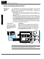
An external power supply is adapted to supply operating voltage to the OP--1312.
The power supply must deliver a range between 8 to 30 VDC, and provide a
minimum of 6 watts continuous power to the units. Connect your power supply using
the terminal block connector supplied with each panel. The connector is keyed to
prevent reversing the polarity. Pin 1 is the positive connection (8--30VDC), while pin
2 is the common (0VDC) or ground connection.
--0V
Ground
+24VDC
1
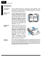
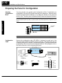
Plug the terminal block connector into Power receptacle
located on the back side of the
panel.
Installation and
Specifications
Use 18--24 AWG conductor wire and connect
the power supply to connector block, which is
supplied with each Operator panel. The terminal marked 1 must have the positive (+8--30
VDC) connected and terminal 2 is common
ground (0V).
Receptacle
2
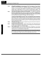
Multi-panel Power In Multi-panel applications, if separate power supplies are used, please ensure the
Supply connection electrical ground common do not have a great potential difference. For the use of a
single power supply in a Multi-panel application, the supply must maintain the
specified voltage and current consumption under all conditions (including power-up)
for each of the individual units. See individual panel power requirements.
(Communications to PLC)
+
OP--9001
Power
Supply
J1
8 to 30 VDC
J2
(RS-422)
etc...
Panel 1
0 VDC
Ground
Power
Supply
Panel 3
Panel 2
Power
Supply
Power
Supply