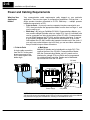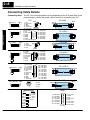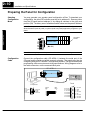
1
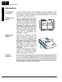
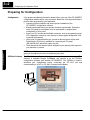
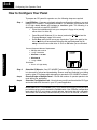
OP--1312
Setpoint/Display Panel
Manual Number OP--1312--M
WARNING
Thank you for purchasing automation equipment from PLCDirectä. We want your new DirectLOGICä automation
equipment to operate safely. Anyone who installs or uses this equipment should read this publication (and any other
relevant publications) before installing or operating the equipment.
To minimize the risk of potential safety problems, you should follow all applicable local and national codes that regulate
the installation and operation of your equipment. These codes vary from area to area and usually change with time. It is
your responsibility to determine which codes should be followed, and to verify that the equipment, installation, and
operation is in compliance with the latest revision of these codes.
At a minimum, you should follow all applicable sections of the National Fire Code, National Electrical Code, and the
codes of the National Electrical Manufacturer’s Association (NEMA). There may be local regulatory or government
offices that can also help determine which codes and standards are necessary for safe installation and operation.
Equipment damage or serious injury to personnel can result from the failure to follow all applicable codes and
standards. We do not guarantee the products described in this publication are suitable for your particular application,
nor do we assume any responsibility for your product design, installation, or operation.
If you have any questions concerning the installation or operation of this equipment, or if you need additional
information, please call us at 1--800--633--0405.
This publication is based on information that was available at the time it was printed. At PLCDirectä we constantly
strive to improve our products and services, so we reserve the right to make changes to the products and/or
publications at any time without notice and without any obligation. This publication may also discuss features that may
not be available in certain revisions of the product.
Trademarks
This publication may contain references to products produced and/or offered by other companies. The product and
company names may be trademarked and are the sole property of their respective owners. PLCDirectä disclaims any
proprietary interest in the marks and names of others.
Stage is a trademark of Koyo Electronics Industries Co., LTD. Think & Do Software is a trademark of Think & Do
Software, Inc. Texas Instruments is a registered trademark of Texas Instruments, Inc. TI, TIWAY, Series 305, Series
405, TI305, and TI405 are trademarks of Texas Instruments, Inc. Siemens and SIMATIC are registered trademarks of
Siemens, AG. GE is a registered trademark of General Electric Corporation. Series One is a registered trademark of
GE Fanuc Automation North America, Inc. MODBUS is a registered trademark of Gould, Inc. IBM is a registered
trademark of International Business Machines. MS-DOS and Microsoft are registered trademarks of Microsoft
Corporation. Windows and Windows NT are trademarks of Microsoft Corporation. OPTOMUX and PAMUX are
trademarks of OPTO 22.
Copyright 1998, PLCDirectä Incorporated
All Rights Reserved
No part of this manual shall be copied, reproduced, or transmitted in any way without the prior, written consent of
PLCDirectä Incorporated. PLCDirectä retains the exclusive rights to all information included in this document.
1
Manual Revisions
If you contact us in reference to this manual, remember to include the revision number.
Title: OP--1312 Setpoint/Display Panel User Manual
Manual Number: OP--1312--M
Issue
Date
Original
11/95
Rev A
Rev B
Effective Pages
Description of Changes
Original Issue
3/96
Cover/Copyright
Contents
Manual Revisions
1 — 32
Index
10
6/98
All pages
Downsize format
Made minor revisions prior to reprinting
Pinout diagram for OP-4CBL-1 cable
showed the wrong pins tied together
1
EU Information
This product is manufactured in compliance with European Union (EU) Directives and carries the CE
mark. The following information is provided to comply with EU documentation requirements.
NOTE: Products with CE marks perform their required functions safely and adhere
to relevant standards as specified by EC directives provided they are used
according to their intended purpose and that the instructions in this manual are
adhered to. The protection provided by the equipment may be impaired if this
equipment is used in a manner not specified in this manual. Only replacement parts
supplied by PLCDirect or its agents should be used. A listing of international affiliates
is available at our Web site
http://www.plcdirect.com
Technical Support
If you need technical assistance, please call the technical support group at
PLCDirect (3505 Hutchinson Rd., Cumming, GA 30040, U.S.A.) at 800--633--0405.
They are available Monday through Friday from 9:00 A.M. to 6:00 P.M. Eastern
Standard Time. Their Web Site address is
http://www.plcdirect.com
SELV Circuits
All electrical circuits connected to the communications port receptacle are rated as
Safety Extra Low Voltage (SELV).
Environmental
Specifications
Operating Temperature . . . . . . . . . . . . . . . . . . . . . 0° to 50° C
Storage Temperature . . . . . . . . . . . . . . . . . . . . . . --20° to 70° C
Operating Humidity . . . . . . . . . . . . . . . . . . . . . . . . 95% (non-condensing)
Air Composition . . . . . . . . . . . . . . . . . . . . . . . . . . . No corrosive gases permitted
Preventative
Maintenance and
Cleaning
No preventative maintenance is required. To clean the exterior of the panel
disconnect the input power and carefully wipe the panel with a cloth moistened with
plain water.
External Fuse
Protection
for Input Power
There are no internal fuses for the input power circuits, so external circuit protection
is needed to ensure the safety of service personnel and the safe operation of the
equipment itself. To comply with EU specifications, the input power must be fused.
Use a fuse rated at twice the input current rating of the panel. For example, if the
panel has an input current rating of 0.5 amperes, use a fuse rated for 1 ampere.
1
Table of Contents
i
Getting Started
Introduction . . . . . . . . . . . . . . . . . . . . . . . . . . . . . . . . . . . . . . . . . . . . . . . . . . . . . . . . . . . . . . . . . . . . . . . . .
The Purpose of this Manual . . . . . . . . . . . . . . . . . . . . . . . . . . . . . . . . . . . . . . . . . . . . . . . . . . . . . . . . .
Contents of the Manual . . . . . . . . . . . . . . . . . . . . . . . . . . . . . . . . . . . . . . . . . . . . . . . . . . . . . . . . . . . .
Supplemental Manuals . . . . . . . . . . . . . . . . . . . . . . . . . . . . . . . . . . . . . . . . . . . . . . . . . . . . . . . . . . . . .
Technical Assistance . . . . . . . . . . . . . . . . . . . . . . . . . . . . . . . . . . . . . . . . . . . . . . . . . . . . . . . . . . . . . .
Chapters . . . . . . . . . . . . . . . . . . . . . . . . . . . . . . . . . . . . . . . . . . . . . . . . . . . . . . . . . . . . . . . . . . . . . . . . .
How the OP-1312 Works . . . . . . . . . . . . . . . . . . . . . . . . . . . . . . . . . . . . . . . . . . . . . . . . . . . . . . . . . . .
The Interaction with Ladder Logic . . . . . . . . . . . . . . . . . . . . . . . . . . . . . . . . . . . . . . . . . . . . . . . . . . .
Using the Setpoint/Display Panel...5 Easy Steps . . . . . . . . . . . . . . . . . . . . . . . . . . . . . . . . . . . . . . .
Step 1: Prepare Your Field Point Labels . . . . . . . . . . . . . . . . . . . . . . . . . . . . . . . . . . . . . . . . . . . . . .
Step 2: Install the Panel . . . . . . . . . . . . . . . . . . . . . . . . . . . . . . . . . . . . . . . . . . . . . . . . . . . . . . . . . . . .
Step 3: Load the OP--WINEDIT Software . . . . . . . . . . . . . . . . . . . . . . . . . . . . . . . . . . . . . . . . . . . . .
Step 4: Configure the Panel to Work with your CPU . . . . . . . . . . . . . . . . . . . . . . . . . . . . . . . . . . . .
Step 5: Write the Ladder Logic . . . . . . . . . . . . . . . . . . . . . . . . . . . . . . . . . . . . . . . . . . . . . . . . . . . . . .
1--2
1--2
1--2
1--2
1--2
1--3
1--4
1--5
1--6
1--6
1--6
1--6
1--6
1--6
Installation and Specifications
Preparing the Setpoint/Display Labels . . . . . . . . . . . . . . . . . . . . . . . . . . . . . . . . . . . . . . . . . . . . . . . .
Applying Text to Each Label . . . . . . . . . . . . . . . . . . . . . . . . . . . . . . . . . . . . . . . . . . . . . . . . . . . . . . . .
Template for Creating Labels . . . . . . . . . . . . . . . . . . . . . . . . . . . . . . . . . . . . . . . . . . . . . . . . . . . . . . . . .
Panel Specifications . . . . . . . . . . . . . . . . . . . . . . . . . . . . . . . . . . . . . . . . . . . . . . . . . . . . . . . . . . . . . . . . .
Physical Specifications . . . . . . . . . . . . . . . . . . . . . . . . . . . . . . . . . . . . . . . . . . . . . . . . . . . . . . . . . . . . .
Environmental Specifications . . . . . . . . . . . . . . . . . . . . . . . . . . . . . . . . . . . . . . . . . . . . . . . . . . . . . . .
Operating Specifications . . . . . . . . . . . . . . . . . . . . . . . . . . . . . . . . . . . . . . . . . . . . . . . . . . . . . . . . . . .
Dimensions for Mounting . . . . . . . . . . . . . . . . . . . . . . . . . . . . . . . . . . . . . . . . . . . . . . . . . . . . . . . . . . . .
Power and Cabling Requirements . . . . . . . . . . . . . . . . . . . . . . . . . . . . . . . . . . . . . . . . . . . . . . . . . . . .
What Are Your Application Needs? . . . . . . . . . . . . . . . . . . . . . . . . . . . . . . . . . . . . . . . . . . . . . . . . . .
Choosing your Connecting Cables . . . . . . . . . . . . . . . . . . . . . . . . . . . . . . . . . . . . . . . . . . . . . . . . . . .
Connecting Cable Details . . . . . . . . . . . . . . . . . . . . . . . . . . . . . . . . . . . . . . . . . . . . . . . . . . . . . . . . . . . .
Connecting Cable . . . . . . . . . . . . . . . . . . . . . . . . . . . . . . . . . . . . . . . . . . . . . . . . . . . . . . . . . . . . . . . . .
Connecting a Power Supply . . . . . . . . . . . . . . . . . . . . . . . . . . . . . . . . . . . . . . . . . . . . . . . . . . . . . . . . . .
Power Supply Connections . . . . . . . . . . . . . . . . . . . . . . . . . . . . . . . . . . . . . . . . . . . . . . . . . . . . . . . . .
Multi-panel Power Supply connection . . . . . . . . . . . . . . . . . . . . . . . . . . . . . . . . . . . . . . . . . . . . . . . .
Preparing the Panel for Configuration . . . . . . . . . . . . . . . . . . . . . . . . . . . . . . . . . . . . . . . . . . . . . . . . .
Selecting Configuration Mode . . . . . . . . . . . . . . . . . . . . . . . . . . . . . . . . . . . . . . . . . . . . . . . . . . . . . . .
Configuration Cable . . . . . . . . . . . . . . . . . . . . . . . . . . . . . . . . . . . . . . . . . . . . . . . . . . . . . . . . . . . . . . .
Preparing the Panel for Communications . . . . . . . . . . . . . . . . . . . . . . . . . . . . . . . . . . . . . . . . . . . . .
Assigning an Address . . . . . . . . . . . . . . . . . . . . . . . . . . . . . . . . . . . . . . . . . . . . . . . . . . . . . . . . . . . . . .
How to Set the Address . . . . . . . . . . . . . . . . . . . . . . . . . . . . . . . . . . . . . . . . . . . . . . . . . . . . . . . . . . . .
OP--9001 Multi-Panel Configurations . . . . . . . . . . . . . . . . . . . . . . . . . . . . . . . . . . . . . . . . . . . . . . . . . .
The Termination Resistor . . . . . . . . . . . . . . . . . . . . . . . . . . . . . . . . . . . . . . . . . . . . . . . . . . . . . . . . . . .
2--2
2--2
2--3
2--4
2--4
2--4
2--4
2--5
2--6
2--6
2--7
2--8
2--8
2--9
2--9
2--9
2--10
2--10
2--10
2--11
2--11
2--11
2--11
2--11
ii
Table of Contents
Configuring Your Operator Panel
Preparing for Configuration . . . . . . . . . . . . . . . . . . . . . . . . . . . . . . . . . . . . . . . . . . . . . . . . . . . . . . . . . .
Configuration . . . . . . . . . . . . . . . . . . . . . . . . . . . . . . . . . . . . . . . . . . . . . . . . . . . . . . . . . . . . . . . . . . . . .
OPEditor Software . . . . . . . . . . . . . . . . . . . . . . . . . . . . . . . . . . . . . . . . . . . . . . . . . . . . . . . . . . . . . . . .
More about OPWIN--EDIT . . . . . . . . . . . . . . . . . . . . . . . . . . . . . . . . . . . . . . . . . . . . . . . . . . . . . . . . . .
The HELP System . . . . . . . . . . . . . . . . . . . . . . . . . . . . . . . . . . . . . . . . . . . . . . . . . . . . . . . . . . . . . . . . .
System Requirements . . . . . . . . . . . . . . . . . . . . . . . . . . . . . . . . . . . . . . . . . . . . . . . . . . . . . . . . . . . . .
How to Configure Your Panel . . . . . . . . . . . . . . . . . . . . . . . . . . . . . . . . . . . . . . . . . . . . . . . . . . . . . . . . .
Step 1 . . . . . . . . . . . . . . . . . . . . . . . . . . . . . . . . . . . . . . . . . . . . . . . . . . . . . . . . . . . . . . . . . . . . . . . . . . .
Step 2 . . . . . . . . . . . . . . . . . . . . . . . . . . . . . . . . . . . . . . . . . . . . . . . . . . . . . . . . . . . . . . . . . . . . . . . . . . .
Step 3 . . . . . . . . . . . . . . . . . . . . . . . . . . . . . . . . . . . . . . . . . . . . . . . . . . . . . . . . . . . . . . . . . . . . . . . . . . .
Step 4 . . . . . . . . . . . . . . . . . . . . . . . . . . . . . . . . . . . . . . . . . . . . . . . . . . . . . . . . . . . . . . . . . . . . . . . . . . .
Step 5 . . . . . . . . . . . . . . . . . . . . . . . . . . . . . . . . . . . . . . . . . . . . . . . . . . . . . . . . . . . . . . . . . . . . . . . . . . .
Step 6 . . . . . . . . . . . . . . . . . . . . . . . . . . . . . . . . . . . . . . . . . . . . . . . . . . . . . . . . . . . . . . . . . . . . . . . . . . .
Step 7 . . . . . . . . . . . . . . . . . . . . . . . . . . . . . . . . . . . . . . . . . . . . . . . . . . . . . . . . . . . . . . . . . . . . . . . . . . .
Step 8 . . . . . . . . . . . . . . . . . . . . . . . . . . . . . . . . . . . . . . . . . . . . . . . . . . . . . . . . . . . . . . . . . . . . . . . . . . .
Step 9 . . . . . . . . . . . . . . . . . . . . . . . . . . . . . . . . . . . . . . . . . . . . . . . . . . . . . . . . . . . . . . . . . . . . . . . . . . .
Step 10 . . . . . . . . . . . . . . . . . . . . . . . . . . . . . . . . . . . . . . . . . . . . . . . . . . . . . . . . . . . . . . . . . . . . . . . . . .
3--2
3--2
3--2
3--3
3--3
3--3
3--4
3--4
3--4
3--4
3--4
3--5
3--6
3--6
3--6
3--6
3--6
Applying Ladder Logic
General Concepts . . . . . . . . . . . . . . . . . . . . . . . . . . . . . . . . . . . . . . . . . . . . . . . . . . . . . . . . . . . . . . . . . . .
Base Register Addresses for PLCDirect Memory . . . . . . . . . . . . . . . . . . . . . . . . . . . . . . . . . . . . . .
Memory Mapping . . . . . . . . . . . . . . . . . . . . . . . . . . . . . . . . . . . . . . . . . . . . . . . . . . . . . . . . . . . . . . . . . .
Addressing Conventions . . . . . . . . . . . . . . . . . . . . . . . . . . . . . . . . . . . . . . . . . . . . . . . . . . . . . . . . . . .
Force Setpoint Registers . . . . . . . . . . . . . . . . . . . . . . . . . . . . . . . . . . . . . . . . . . . . . . . . . . . . . . . . . . .
Using the Panel with PLCDirect . . . . . . . . . . . . . . . . . . . . . . . . . . . . . . . . . . . . . . . . . . . . . . . . . . . . . .
Writing Display Data to the PLC Memory . . . . . . . . . . . . . . . . . . . . . . . . . . . . . . . . . . . . . . . . . . . . .
Forcing Setpoint Data to the PLC Memory for the DL205/DL405 . . . . . . . . . . . . . . . . . . . . . . . . .
Forcing Setpoint Data to the PLC Memory for the DL305 . . . . . . . . . . . . . . . . . . . . . . . . . . . . . . .
Using the Panel with an Allen-Bradley PLC . . . . . . . . . . . . . . . . . . . . . . . . . . . . . . . . . . . . . . . . . . . .
Writing Display Data to the PLC Memory . . . . . . . . . . . . . . . . . . . . . . . . . . . . . . . . . . . . . . . . . . . . .
Forcing Setpoint Data to the PLC Memory . . . . . . . . . . . . . . . . . . . . . . . . . . . . . . . . . . . . . . . . . . . .
Bit Manipulation in the Force Flag Register . . . . . . . . . . . . . . . . . . . . . . . . . . . . . . . . . . . . . . . . . . .
Controlling Individual Bits . . . . . . . . . . . . . . . . . . . . . . . . . . . . . . . . . . . . . . . . . . . . . . . . . . . . . . . . . . .
Bit-of-Word . . . . . . . . . . . . . . . . . . . . . . . . . . . . . . . . . . . . . . . . . . . . . . . . . . . . . . . . . . . . . . . . . . . . . . .
Internal Relays . . . . . . . . . . . . . . . . . . . . . . . . . . . . . . . . . . . . . . . . . . . . . . . . . . . . . . . . . . . . . . . . . . . .
4--2
4--2
4--3
4--3
4--5
4--6
4--6
4--7
4--8
4--9
4--9
4--10
4--11
4--11
4--11
4--12
Getting Started
1
1
In This Chapter. . . .
— Introduction
— Using the Setpoint/Display Panel ... 5 Easy Steps
1--2
Getting Started
Getting Started
Introduction
The Purpose of
this Manual
This User Manual provides user information on panel installation, panel
configuration, and programming the OP1312 Setpoint/Display Panel. The purpose
of this manual is to teach concept and programming techniques which may be
applied while implementing the panel.
Contents of the
Manual
Inside this manual you will learn about
using the OptiMate OP--1312 panel. It
includes wiring diagrams and power
requirements, as well as the information
you need for selecting the proper cables.
We will show how to use the
OPWIN--EDIT configuration software
(purchased separately) to configure your
panel. And in the back of this manual, we
will show you some simple ladder logic
that demonstrates the versatility of the
panel, both for Allen-Bradley and
PLCDirectt products.
How to
Use the
OP-1312
OP-1312
The OP-1500 and OP-1510
Operator panels may be
reconfigured to exchange data
with
your
programmable
controller.
Supplemental
Manuals
Reference the appropriate PLC/CPU
User Manuals for the commands and
address references required for your
system. If you are using a DirectLOGIC
PLC product, you will want to keep the
DirectSOFT User Manual handy while
programming your system. For other
PLC brands you must reference their
User manuals to properly program the
ladder logic required to operate the
OP-panels.
For Multi-Panel applications utilizing the
OP-9001
Communications
Master
please refer to the OP--9001 User
Manual (Part Number OP--9001--M).
Technical
Assistance
After completely reading this manual, if you are not successful with implementing the
OP--1312, you may call PLCDirect at (800) 633-0405, Monday through Friday from
9:00 A.M. to 6:00 P.M. Eastern Standard Time. Our technical support group will work
with you in answering your application questions. If you have a comment or question
about our products, services, or manuals which we provide, please fill out and return
the suggestions card included with this manual.
Getting Started
Chapters
1--3
This table provides an overall description of the topics covered within this manual.
Getting Started
2
Installation and
Specifications
3
Configuring Your Panel
4
Applying Ladder Logic
Shows how to prepare for system installation, including specifications and
mounting instructions. Includes connecting cables part numbers and
specifications.
shows how to configure the panel. The OP--WINEDIT for windows
contains Help windows which will assist with configuring the panel.
Explain the memory map and how to program and operate the panel.
Getting Started
1
Introduces the physical and functional characteristics. Also provides
introduction to planning your system.
Getting Started
1--4
Getting Started
How the OP-1312
Works
You’ll notice the OP-1312 has three LED windows with four labels beneath each of
them. There are a total of twelve labels. Each of the labels refer to user-defined field
points. These field points are actually memory locations inside your PLC where data
is stored. During configuration with the OPEditor software, you define and link these
field points to your panel. You can make a field point a read only location--in which
case, we refer to it as display data. Or you can designate a field point to store
setpoint data--in which case, the field point is a read/write location. The three LED
windows allow you to either read the display data or read and write the setpoint data.
Each label has an LED beside it. When an LED is lit, it means you have connected
the corresponding field point (in the PLC) to the panel window immediately above
the corresponding label. Let’s look at an illustrated example.
The illustration at the bottom--right of the page, shows a display window with its
four labels. Notice that beneath each bank of four labels are arrow keys and a
<SELECT>key. Pressing any<SELECT> key successively moves you up and
down the labels immediately above the key; and as their corresponding LED
becomes lit, the window displays the data from the field point memory location
that is linked to the label. If you move to a label whose field point has been setup
by you to hold setpoint data, then you can use the UP or DOWN ARROWS to
change the value shown in the window. The UP or DOWN ARROWS have no
effect,however on field points that have been setup for display data.
Now look at the memory map in the illustration. We have used the OPEditor
during configuration to map each of the 12 field points and a forcing function to
consecutive memory areas inside the respective PLC. For the PLCDirect
product, it started at V2000. For the Allen-Bradley product it started at N7:0. The
memory map shown is merely an example. Your base address in the PLC for the
mapping can start at any available memory location, as long as you use
consecutive locations. The download precedure (explained later) will consume
224 consecutive bits of memory--devoted entirely to the OP-1312 operations.
Below we show this as 14 consecutive 16-bit registers. If you are using the
DL305 family, it would consume 28 consecutive 8-bit registers. We’ll give you
specific examples later.
CPU Memory
PLCDirect
OP--1312 to CPU
Memory Map
N7:0
--OR-Allen-Bradley
Display Locations
Allen-Bradley PLCDirect
V2000
Location 1 data
N7:1
V2001
Location 2 data
N7:2
V2002
Location 3 data
N7:3
N7:4
V2003
V2004
Location 5 data
N7:5
V2005
Location 6 data
N7:6
V2006
Location 7 data
Location 4 data
N7:7
V2007
Location 8 data
N7:8
V2010
Location 9 data
N7:9
V2011
Location 10 data
N7:10
V2012
Location 11 data
N7:11
V2013
Location 12 data
N7:12
V2014
Force data info
N7:13
V2015
Data to be forced
Target Production
Current Production
Press Temperature
Air Pressure
Press to select location
to change or view
Press arrow
keys to change
setpoints
1--5
Getting Started
Numbers refer to
field point
designations
3
2
1
9
4
12
5
7
Ladder Logic Example ( PLCDirect )
Target production is written to V2000 by the
OP-1312.
X10
X11
CNT
CT0
V2000
Current production count gets copied
into V2001, which is being read by
the setpoint unit. (V1000 holds the
current count for CT0.)
X10
OP--1312 to CPU
Memory Map
V2000
Location 1
Setpoint
Location 2
Display
V2002
Location 3
Location 4
Location 5
V2005
Location 6
V2006
Location 7
V2007
Location 8
V2010
Location 9
LD
V1000
V2011
Location 10
V2012
Location 11
OUT
V2001
V2013
Location 12
V2014
Force data
V2015
Data to force
11
6
8
Display
V2001
V2003
V2004
10
Target Production
Current Production
Press Temperature
Air Pressure
Target Production
Current Production
Press Temperature
Air Pressure
Use keys to
change setpoint
Press SELECT to move
to the next data location. Here we have
moved to Label 2 and
we are reading the current count out of
V2001.
Getting Started
While we explained on the opposite page how the memory mapping process
between the panel and the PLC takes place, we haven’t yet explained how you use
the linked “field points” in your PLC operations. This is done with ladder logic.
Suppose you have a DL205 or DL405 family PLC. Below (center) shows the
memory mapping if we have used V2000 as our base register address. In this
example, we are tracking “current production” against our “target production”.
Look at the ladder logic on the left in the diagram.
X10 is an input from a photoeye to a PLC counter (CT0). X10 is the input that
increments the counter and X11 is connected to a reset button. For purposes of
our illustration, we don’t need to know anything else about the process. Looking
again at our labels and display window, be aware that the labels are numbered 1
through 12 left-to-right, top-to-bottom. So Location 1 refers to the Target
Production label. Location 2 refers to the Current Production label, and so
forth.
We are using the data placed in V2000 as our preset for the counter in our ladder
logic. You will notice at the upper right-hand side of the illustration that we have
entered 1243 as the data (setpoint) we place in V2000.
Because we are using a DL205 or DL405, we know that the current count for
Counter Number Zero (CT0) is always stored in V1000. Thus with the ladder
logic shown, everytime the X10 comes ON and increments the counter, the
current count gets copied into V2001. We wanted this copied to V2001 because
we have configured V2001 to be a display data point (read only), and we have
placed the words “Current Production” on its corresponding label (Label 2). See
how easy it is? We’ll show you other examples later.
The Interaction
with Ladder Logic
1--6
Getting Started
Getting Started
Using the Setpoint/Display Panel...5 Easy Steps
Step 1: Prepare
Your Field Point
Labels
First, you need to prepare the labels for each of
the field points. The labels insert into plastic
sleeves behind the main cover. To access the
sleeves, you merely snap loose the front bezel.
Decide ahead of time which field points are
display only and which are read/write
setpoints. You need this information for your
configuration process.
Step 2: Install the
Panel
Preparing for installation, you will want to
check the individual specifications. These
include dimensions, power requirements,
cabling requirements, and NEMA ratings.
We include information you will need for
mounting; i.e. cutout dimensions, cabling
requirements, components needed, etc.
Panel
Step 3: Load the
OP--WINEDIT
Software
You need the OptiMatet
OP--WINEDIT software in order
to configure your panel. This
software is the same regardless
of whether you are connecting to
PLCDirect or Allen-Bradley
product.
Step 4: Configure
the Panel to Work
with your CPU
After setting a DIP switch on the rear of the panel
and attaching the programming cable, you are
ready to configure your panel. The simple and
easy-to-follow screens make configuration a
painless process. You do not have to be
connected to the panel at this point.
Step 5: Write the
Ladder Logic
The amount of ladder logic programming
knowledge you need is very basic. In most
cases, you are already familiar with the
elements of logic that are required. We’ll
give you examples in the final section of
this manual, and you will see right away
just how easy it is.
Cables
External Power
Your PC
OptiMate
OptiMate Configuration
Editor Version 3.2 6/98
DIP
Switch
X10
X11
X10
CNT
CT0
V2000
LD
V1000
OUT
V2001
Installation and
Specifications
In This Chapter. . . .
— Preparing Panel Labels
— Template for Creating labels
— Panel Specifications
— Dimensions for Mounting
— Power and Cabling Requirements
— Connecting a Power Supply
— Preparing Panel for Configuration
— Preparing Panel for Communications
— OP--9001 Multi--panel Configurations
2
2--2
Installation and Specifications
Preparing the Setpoint/Display Labels
You may create custom labels for your application. Either use the OP--WINEDIT
Help screens template which allows label entry and printout, or use the template
provided on the next page.
Installation and
Specifications
Applying Text to
Each Label
Preparing the Setpoint/Display labels for the OP--1312 panel requires you to slide a
legend transparency into a pocket in the panel overlay. Use the following procedure:
1. Remove the bezel from the module by unsnapping the four tangs that hold
the bezel to the module frame.
2. Create a legend transparency for each of the 3 label areas. There are
several ways of doing this. A pattern is provided on the next page that gives
you the available dimensions. The nicest legends result from using a
computer graphics program and a laser printer to create the transparency.
Finished Legend
Insert legend between window frame
and cabinet
Bezel
3. Use the pattern on the next page to cut out the legend from the
transparency sheet.
4. Slide the finished legend into the pocket space between the front cover and
the panel housing.
5. Re--attach the bezel by snapping the bezel onto the case.
Installation and Specifications
2--3
Template for Creating Labels
Copy this entire page onto a sheet of standard 8 1/2 x 11 white paper using a copy machine. With
a typewriter or computer, type the text inside the parallel lines that separate each label. Copy again
onto standard 8 1/2 x 11 clear transparency film. Cut with scissors along outside perimeter of each
legend. Insert each legend into the plastic sleeves behind the removable front bezel. There are
three separate sleeves.
(Actual Size)
Installation and
Specifications
Dimensions
0.25”
2.15”
0.05”
1.68”
2--4
Installation and Specifications
Panel Specifications
Physical
Specifications
Weight . . . . . . . . . . . . . . . . . . . . . . . . . . . . . . . . . . 22 ounces
Panel Fasteners . . . . . . . . . . . . . . . . . . . . . . . . . . Four 6x32 threaded studs
NEMA Rating . . . . . . . . . . . . . . . . . . . . . . . . . . . . . NEMA 4 (when properly installed)
Installation and
Specifications
Environmental
Specifications
Operating Temperature . . . . . . . . . . . . . . . . . . . . . 0° to 50° C
Storage Temperature . . . . . . . . . . . . . . . . . . . . . . --20° to 80° C
Operating Humidity . . . . . . . . . . . . . . . . . . . . . . . . 5 to 95% (non-condensing)
Air Composition . . . . . . . . . . . . . . . . . . . . . . . . . . . No corrosive gases permitted
Operating
Specifications
Power Budget Requirements . . . . . . . . . . . . . . . . 6 VA @ 8--30 VDC
0.31 A @ 12 VDC (all LEDs OFF)
0.48 A @ 12 VDC (all LEDs ON)
0.16 A @ 24 VDC (all LEDs OFF)
0.24 A @ 24 VDC (all LEDs ON)
Power Connector . . . . . . . . . . . . . . . . . . . . . . . . . . Removable Terminal Block (2 position)
Minimum Supply Voltage . . . . . . . . . . . . . . . . . . . +8 VDC
Maximum Supply Voltage . . . . . . . . . . . . . . . . . . . +32 VDC
Diagnostics . . . . . . . . . . . . . . . . . . . . . . . . . . . . . . . Power On, CPU
Communication Link . . . . . . . . . . . . . . . . . . . . . . . RS-232 for distance less than 50ft
RS-422 for distance up to 4000ft.
4800, 9600 and 19200* baud
15-pin female D type connector
*19200 baud rates will not
work with Allen-Bradley PLCs.
Connector Kits . . . . . . . . . . . . . . . . . . . . . . . . . . . . OP--CMCON--1: pack of 4 ribbon cable
connectors.
OP--CMCON--2: pack of 4 solder type
connectors.
OP--CMCON--3: (2) D-Shell connectors
w/ terminal block. (Multi-panel appl. )
OP--PSCON: pack of 4--24VDC power
supply connectors w/ terminals.
Installation and Specifications
2--5
Dimensions for Mounting
Installation and
Specifications
Cutout Area
Example panel mounting
Dimensions in Inches
9.50
0.5”
1.00
3.50
2.00
3.5”
8.40
1.00
8.85
1.75”
2--6
Installation and Specifications
Power and Cabling Requirements
Installation and
Specifications
What Are Your
Application
Needs?
Your communication cable requirements really depend on your particular
application. There are two types of configuration possibilities. Point-to-point — a
single operator interface connected to a CPU. Multi-drop — multiple operator
interfaces connected to a CPU.
S Point-to-Point -- If you only need one operator interface connected to one
CPU, then just choose the appropriate cables from the chart on Page 11, and
you’re ready to go!
S Multi-drop -- By using an OptiMate OP--9001 Communications Master, you
can connect multiple Optimate units to a single CPU. Up to 31 individual units
can be connected in a daisy-chain fashion to the OP--9001. Communications
are via RS422 between the OP--9001 and the operator interfaces. If you use
a good quality shielded cable, you can have a total distance of up to 4000
feet between the OP--9001 and the last operator interface unit in the chain. If
you only have a short distance (up to 30 feet), you can use ribbon cable and
easy-to-install crimp-on ribbon connectors.
1. Point-to-Point
A single cable connection
from the PLC to the panel
gives you access to the
PLC’s data registers and
ladder logic.
2. Multi-drop
Multiple OP-panels can be interfaced to a single PLC. This
requires the use of the OP-9001 Communications Master.
With the Communication Master, up to 31 panels can be
interfaced to a single CPU port. Each can be programmed
for entirely different functions. Panels can be distributed
up to 4000 feet* from the OP--9001.
OP--9001
Power
Source
DL405 CPU Base
Power Supply
OP--panels
NOTE: Please read and follow the cabling requirements in the OP-9001 User Manual
(OP-9001-M) when using multiple panels. Failure to follow the guidelines of the User Manual
may affect the integrity of the RS422 link, resulting in communication errors.
Installation and Specifications
Choosing Your
Connecting Cables
OP-9001 Cable Connectors
OptiMate Cables
Family
D
D
D
OP-CMCON--1 — pack of 4
ribbon cable connectors.
OP-CMCON--2 — pack of 4
solder-type connectors.
OP-CMCON--3 — pack of 2
D--shell connectors with screw
terminals for use with OP-9001
& multiple OP-panels.
OP-PSCON — pack of 4 power
supply block connectors.
For electrically noisy environments,
we recommend an individually paired
and shielded cable, such as Belden
9729 or equivalent. This type of cable
will require the solder-type or D-shell
with screw terminal connectors. If
you’re going 30 feet or less, you can
use ribbon cable. For ribbon cable,
we recommend Belden 9L28015 or
3M 3365/15.
* — requires RS232 Data Communications Unit (D3--232--DCU)
** -- also DC versions
Port
Cable
DirectLOGICt
DL105
DL130
Only port
OP--2CBL
DirectLOGICt
DL205
DL230
Only port
OP--2CBL
DL240
Top port
OP--2CBL
Bottom port
OP--2CBL
Top port
OP--2CBL
Bottom port
OP--2CBL--1
D2--DCM (module)
Only port
OP-4CBL--2
DL330
Requires DCU*
OP--4CBL--2
DL330P
Requires DCU*
OP-4CBL--2
DL340
Top port
OP-3CBL
Bottom port
OP-3CBL
Top port
OP-2CBL
Bottom port
OP-4CBL-2
Top port (15-pin)
OP-4CBL--1
Bottom port (25-pin)
OP-4CBL--2
Top port
OP-4CBL--1
Bottom port
OP-4CBL--2
Phone Jack
OP-2CBL
Top port (15-pin)
OP-4CBL--1
Bottom port (25-pin)
OP-4CBL--2
D4--DCM (module)
Only port
OP-4CBL--2
Slice I/O panels
Only port
OP-4CBL--1
GEâ Series 1
IC610CPU105/106
Requires DCU*
OP-4CBL--2
GEâ
All Models (311--351)
RS232, RS422
Serial Port
OP-GCBL--1
GEâ Fanuct
Series 90 Micro
All Models
RS232, RS422
Serial Port
OP-GCBL--1
MODICON
ModBus
RJ45 port
OP-MCBL--1
TI305t /
SIMATICâ TI305t
325--07, PPX:325--07
Requires DCU*
OP-4CBL--2
330--37, PPX:330--37
Requires DCU*
OP-4CBL--2
325S--07 (or 325 w/ Stage Kt)
Requires DCU*
OP-4CBL--2
330S--37, PPX:330S--37
Requires DCU*
OP-4CBL--2
335--37, PPX:335--37
Phone Jacks
OP-3CBL
DL250
DirectLOGICt
DL305
DL350
DirectLOGICt
DL405
If you’re planning to use multiple
panels and an OP-9001, then you’ll
need to build your own custom
cables. Since the proper cable
choice really depends on your
application, we offer the following
connectors.
D
CPU
(or other device)
DL430
DL440**
DL450
Seriest 90/30
TI405t /
SIMATICâ TI405t
If DCU is used*
OP-4CBL--2
425--CPU, PPX:425--CPU **
Only port
OP-4CBL--1
PPX:430--CPU
Top port (15-pin)
OP-4CBL--1
Bottom port (25-pin)
OP-4CBL--2
Top port (15-pin)
OP-4CBL--1
Bottom port (25-pin)
OP-4CBL--2
435--CPU, PPX:435--CPU **
Smart Slicet I/O panels
Only port
OP-4CBL--1
A--B SLC 500
5/03, 5/04
Bottom port
OP-ACBL--1
A-B
MicroLogix
Only port
OP-ACBL--2
Installation and
Specifications
Depending on which PLC you are
using, you may require as many as
two cables. Here are the
requirements:
D
OP-ACBL-1: all units require
this cable for configuration. This
is a 9-pin female to 15-pin male
cable that connects your
personal computer to the
OP-panel. This cable is also
used to connect an OP-panel to
the Allen-Bradley SLC 500
CPUs listed.
D CPU Cables: You will also need
the appropriate cable to connect
your CPU to the OP-panel. Use
the chart shown to the right to
choose
the
correct
communications cable.
2--7
2--8
Installation and Specifications
Connecting Cable Details
The OP--1312 connecting cable may vary depending on the CPU used. Refer to the
previous page to confirm the proper cable is chosen for connecting your PLC.
Installation and
Specifications
Connecting Cable
RJ12 (PLC)
4
3
1
DB15
3
2
5
15-pin (PLC)
2
3
7
4
5
DB15
3
2
5
RJ11 (PLC)
2
1
4
DB15
3
2
5
DB15 (PLC)
2
3
4
13
14
15
1
7
8
DB15
3
2
5
DB25 (PLC)
2
3
7
4
5
DB15
3
2
5
PLC
1= 0V
2= not used
3= Din
4= Dout
5= not used
6= not used
RJ12
RJ12
(6P6C)
15= not used
14= not used
13= not used
12= not used
11= not used
10= not used
9= not used
RJ11
1= Din
2= Dout
3= not used
4= 0V
1 234
8= YOM
7= CTS
6= not used
5= not used
4= On-line
3= Din
2= Dout
1= YOP
25
25= not used
24= not used
23= not used
22= not used
21= not used
20= not used
19= not used
18= not used
17= not used
16= not used
15= not used
14= not used
6 7 8
4
5
12
OP--2CBL--1
15-pin
DB15
OP--3CBL
RJ11
(4P4C)
1515= tied (0V)
14= tied (0V)
13= tied (0V)
12= not used
11= not used
10= not used
9= not used
1
13= not used
12= not used
11= not used
10= not used
9= not used
8= not used
7= 0V
6= not used
5= CTS
4= RTS
3= Din
2= Dout
1
1= not used
3
3= Din
2= Dout
5 =0V
Panel
11 = Dout+
12 = Dout -9 = Din +
10 = Din-5 =0V
DB15
OP--4CBL--1
DB15
DB15
OP--4CBL--2
DB25
Mini--DIN
DB15
OP--ACBL--2
Panel
RS-422 Pinout
PLC
Din +
Din -Dout +
Dout -0V
RTS+
CTS+
RTS-CTS--
DB15
12 3456
8= not used
7= 0V
6= not used
5= CTS
4= RTS
3= RXD
2= TXD
1= not used
8 Pin Mini DIN DB15
7
3
4
2
2
5
OP--2CBL
9= not used
10= not used
11= not used
12= not used
13= not used
14= not used
15= not used
15
DB15
1
1= not used
2= Dout
3= Din
4= not used
5= 0V
6= not used
7= not used
8= not used
2--9
Installation and Specifications
Connecting a Power Supply
Power Supply
Connections
An external power supply is adapted to supply operating voltage to the OP--1312.
The power supply must deliver a range between 8 to 30 VDC, and provide a
minimum of 6 watts continuous power to the units. Connect your power supply using
the terminal block connector supplied with each panel. The connector is keyed to
prevent reversing the polarity. Pin 1 is the positive connection (8--30VDC), while pin
2 is the common (0VDC) or ground connection.
--0V
Ground
+24VDC
1
Plug the terminal block connector into Power receptacle
located on the back side of the
panel.
Installation and
Specifications
Use 18--24 AWG conductor wire and connect
the power supply to connector block, which is
supplied with each Operator panel. The terminal marked 1 must have the positive (+8--30
VDC) connected and terminal 2 is common
ground (0V).
Receptacle
2
Multi-panel Power In Multi-panel applications, if separate power supplies are used, please ensure the
Supply connection electrical ground common do not have a great potential difference. For the use of a
single power supply in a Multi-panel application, the supply must maintain the
specified voltage and current consumption under all conditions (including power-up)
for each of the individual units. See individual panel power requirements.
(Communications to PLC)
+
OP--9001
Power
Supply
J1
8 to 30 VDC
J2
(RS-422)
etc...
Panel 1
0 VDC
Ground
Power
Supply
Panel 3
Panel 2
Power
Supply
Power
Supply
2--10
Installation and Specifications
Preparing the Panel for Configuration
Selecting
Configuration
Mode
You may generate your operator panel configuration off-line. To download your
configuration, the panel DIP switches must be set to address 31. Remove power
from the OP-panel and set address 31 by sliding all switches to the right most
position (ON). The binary sum of all address switch values are the panel’s address.
Installation and
Specifications
NOTE: Set the panel to address No. 31 for online configuration mode. Configuration mode
allows download (write to panel) or upload (read from panel) application programs to your
panel.
ON
Termination
Resistor
SW1 Position 1 2 3 4 5 6
123456
Address Value
1 2 4 8 16 T
(No. 31)
NOTE: You must cycle power to the panel to activate the new switch settings.
Configuration
Cable
Connect the configuration cable (OP--ACBL--1) between the serial port of the
OP-panel and the serial port of the personal computer. The panels may then be
configuring using the OP--WINEDIT configuration software. The figure below shows
programming cable connectors and wiring specifications. Wiring diagrams refer to
the cable connectors, not the communication ports.
OP--ACBL--1
Panel
Computer
1
9
5= 0V
4= not used
3= Dout
2= Din
1= not used
9=not used
8= CTS
7= RTS
6=not used
1
Female
DB9
3
2
5
7
8
Male
DB15
3
2
5
9= not used
10= not used
11= not used
12= not used
13= not used
14= not used
15= not used
1= not used
2= Dout
3= Din
4= not used
5= 0V
6= not used
7= not used
8= not used
Installation and Specifications
2--11
Preparing the Panel for Communications
Assigning an
Address
How to Set the
Address
You can assign any address between 0 and 30 for valid communications to the
OP--9001 or CPU. The address is set with the DIP switch block located on the
back of the units.
The address block contains six slide switches, switch 1 through 5 are used for
addressing your Operator panel. The figure below shows the binary-weighted value
of each switch. If you are using a single panel configuration, all addresses 0--30 are
valid for communicating to the CPU. Remove power from the panel and change
switches 1 through 5 to set the desired panel address.
In this figure we have selected address No.14, placed switches 2, 3 and 4 to the right
(ON), and switches 1 and 5 to the left (OFF).
Example Address
Block Setting
ON
SW1 Position 1 2 3 4 5 6
123456
Address Value
1 2 4 8 16 T
(2 + 4+ 8 = 14)
Termination
Resistor
TIP: You must cycle power to the OP-panel to activate the new switch settings.
OP--9001 Multi-Panel Configurations
If you are connecting more than one OptiMate panel to a single CPU this is referred
to as Multi-panel configuration. Multi-panel configurations require the OP--9001
Communications Master. The OP--9001 communicates with the CPU as well as the
connected OP--panels. The OP--9001 Communications Master looks for an address
within the range of 0 to 30 for each panel connected. Each panel connected in an
RS-422 link must have a unique address. A more detailed description of multiple
panel configurations and installation is given in the OP--9001--M User Manual.
The Termination
Resistor
The last panel must be terminated when using an RS-422 communications link by
setting switch 6 (ON). Operator panels communicating more than 50 feet distance
must use RS-422 links. Systems which are using the OP--9001, in a multi-panel
application use RS-422 wiring and properly set the terminating switch. Switch 6 is
used for terminating an RS-422 communications link.
NOTE: Only the last panel of each RS-422 link should be terminated (switch 6 ON). All other
panels must have switch 6 in the OFF position. After changing the DIP switch settings,
remember to cycle power on the panel to activate the new switch settings.
Installation and
Specifications
NOTE: Set the panel address between 0--30 for valid communications mode.
Configuring Your
Operator Panel
In This Chapter. . . .
— Preparing for Configuration
— How to Configure Your Panel
3
3--2
Configuring Your Operator Panel
Preparing for Configuration
Configuring Your
Operator Panel
Configuring Your
Operator Panel
System Setup
Configuration
If you prepare and plan all information ahead of time, your use of the OP--WINEDIT
configuration software will be very successful. Below are a few important items to
perform while programming your application.
S Prepare personal computer and ensure proper installation of the
OP--WINEDIT configuration software.
S Examine and understand your operator interface requirements. Determine
which OP--panel(s) are needed, and if a single panel or multiple panel
configuration is to be used.
S Know your PLC product and available resources, such as programming tools,
CPU capabilities, unused or user memory for base register assignment (128
consecutive bits/panel)
S Verify type of communications port, as well as which protocol will be used.
Determine the CPU link(s) available for connecting an OP--panel
(RS--232/RS--422, baud rate, parity, stop bit).
S Think about how the features will be assigned in your panel(s) with respect to
your machine or process.
NOTE: In addition to these instructions, use the OP--WINEDIT Help screens to
guide you through the process of configuring your panel.
OPEditor Software The OP--1312 is configured with software running on a personal computer. This
software is available through PLCDirect, and referred to as the OPEditor
configuration software (part number OP--WINEDIT). The OPEditor is used to
download your configuration before connecting the OP--1312 unit and
communicating to a PLC or OP--9001 Communication Master.
Configuring Your Operator Panel
More about
OPWIN--EDIT
The HELP System
3--3
The OPEditor configuration software allows you to configure OP--panel
applications, as well as download (write to panel) and upload (read from panel) the
configurations. Use this software to configure your communication link(s), select
pushbutton control, and enter operator display messages. The newer and most
recommended software is the OP--WINEDIT package. This windows software may
be ordered from PLCDirect using part number OP--WINEDIT.
For the OP--WINEDIT software (e.g. version 1.01 or greater) configuration Help
windows are provided for performing all necessary configuration tasks. Should you
have problems understanding how to program your panel, refer to these built--in On
Line Help windows. To call the Help windows, point and click on the Help menu and
choose Using help, or click on the [?] ICON located near the top of the main
configuration window.
save them to disk. The programs may then be downloaded to the OP--panel(s).
System
Requirements
Operator Panel
The OP--WINEDIT software, must have the following minimum PC configuration:
S IBM 386 (or better) compatible computer
S VGA or SVGA video board and color monitor
S 1 meg of free hard drive space
S 1 meg of RAM memory
S Windows 3.1 or higher (OP--WINEDIT)
Operator Panel
TIP: You may design and configure your Operator Panel configuration(s) offline and
3--4
Configuring Your Operator Panel
How to Configure Your Panel
System Setup
Step 1
Personal Computer Minimum Requirements:
Configuring Your
Operator Panel
3 IBM type 386 or above
3 1 meg of hard drive
3 Windows 3.1 or later
3 Windows 95
3 1 meg of RAM
Disk Media:
3 One 3--1/2” high density
Step 2
Step 3
Configuring Your
Operator Panel
To prepare an OP--panel for operator use, the following steps are required.
Load OPEditor -- If you are not already using the configuration software, you must
install the OP--WINEDIT configuration software. The software is provided on one
3--1/2” high density diskette and includes an installation guide. The following is a
description on how to install OP--WINEDIT.
S Place the installation disk into your computer’s floppy drive (usually
either drive A or drive B).
S Open Microsoft Windows (3.0 or above) and select File/Run from the
Program Manager (upper--left corner).
S Select Run, and you will see a pop--up window. Type in the path for the
drive in which you have placed the setup disk and designate the file
setup. Here we have used drive A. Click on OK when you are finished.
Step 4
Direct
LOGIC
PLC
OptiMate
OP-WINEDIT
Select the COM ports -- Your OP--WINEDIT software requires you select which port
is to be used for upload and downloading. Ensure serial port selected is not being
used by other PC software while attempting to operate the OP--WINEDIT software.
Choose Single or Multiple Panel -- Decide the number of operator panels to be
used within your application.
Select the Configuration Link -- Here is where you will need to select the PLC type
and model which will be used in your OP--panel application.
DirectLOGIC PLCs : Some DirectLOGIC CPUs feature a secondary communication
port which may be used to connect the OptiMate units. Your OPEditor configuration
must match the PLC port setups, such as address, baud rate, stop bits, and parity.
Also ensure the secondary communications port is set for HEX mode, not ASCII.
Configuring Your Operator Panel
Step 5
3--5
Complete the Communications Information -- After you have selected the PLC
type you must define the remaining protocol items , such as the baud rate, parity and
stop bit settings. The following table provides the necessary information for most
PLCDirect controllers. In the case of using other PLC product and family, you should
reference the proper product User manual(s) to determine the port communications
capabilities.
PLC Model
Port/Baud Rates
DL105/230/240
9600
Top
Bottom Bottom (DL240 only)
9600/19.2k
DL250
Top 9600
Parity
Stop
Bit
Odd
1
Odd/None
Odd/None
DL330
DCU only 4800/9600/19.2k
Odd/None
1
DL340
Bottom &Top 4800/9600/19.2k
Odd/None
1
DL350
Top 9600
Odd
Bottom 4800/9600/19.2K
DL430/440
Top Top
9600
DL450
DB15 9600
1
Odd
Odd/None
1
Odd
DB25 9600/19.2k
Odd/None
RJ12 9600/19.2k
Odd/None
1
During configuration, ensure that your address and communications
parameters match the PLC port settings. There will be a selection for PLC timeout.
When the panel sends a message to the PLC and does not receive a response or
does not understand the response, it will wait the time--out period before resending
the message. A communication failure after 12 seconds initiates the message “Host
Communication Fail” on the panel.
You also have several ports which can be used to connect your communications
cable. Some of these ports have fixed PLC address assignments, and some do not.
The ports which allow configuring the PLC addresses can be set to a unique
address, ranging from 1 through 90. Refer to your User Manual for specific
information on the ports of your PLC.
OTHER PLCs : For Allen--Bradley, you will need to connect to Channel 0 (bottom serial
port), using DF1 full duplex. Additionally, the Allen--Bradley software allows you to
set the bottom port to a unique PLC address. The software default is PLC Address 1.
You must select CRC error detection and ensure the address on the configuration
screen matches the address you have assigned. This port must also be configured
for either 4800 or 9600 baud. No other baud rates are supported for communicating
between the OP--panels and an Allen--Bradley PLC. Since the Allen--Bradley
software uses a default baud rate of 1200, you must change the settings.
Operator Panel
Bottom 9600/19.2k
Odd/None
Operator Panel
1
Bottom 9600/19.2K
3--6
Configuring Your Operator Panel
Step 6
System Setup
Step 7
Step 8
Configuring Your
Operator Panel
Configuring Your
Operator Panel
Step 9
Step 10
Select the Panel Address -- The panel has a DIP switch on the rear of the unit which
is used to set the panel address (between 0--31). This address is used for two
functions. The first function is for setting the address for configuration and the
second is for the specific panel address. This panel address (0--31) is used with
multiple panel configurations and the OP--9001 Communications Master. The
address number that you select on the switch must also be configured to the panel.
Select the Base Register Address and File Number -- This step is very important
because it establishes the link in your PLC memory to the panel. For DirectLOGIC
PLCs, the following section describes the mapping process. Once you are familiar
with the mapping process and you know the memory in your PLC to use (refer to the
user manual for your respective PLC type), enter your selection.
If you choose Allen--Bradley as your PLC Type, you must enter the PLC File Number
in addition to a Base Register Address. You must expand the memory map in the
Allen--Bradley PLC to include all registers being used by the OP--panel. The panel
will only recognize integer file types N7 and user--defined file types N9 through
N255. Enter the number only and not the prefix N. The Base Register Address is any
number between 0 and 255.
Select the Panel Type -- Since the configuration program is the same for all panels,
you will need to select OP--1312.
Configure the Panel Functions -- Prepare the functions of the panel and how the
operator control shall work for the features you are selecting to use. These features
are discussed in detail in the following chapter.
Save and Download -- Once you have completed your configuration, you can save
it to disk and/or write directly to the panel. If saving to the panel, verify that the DIP
switch is set to 31 to download the configuration.
NOTE: After your configuration has been properly downloaded, you will need to reset
the DIP switch to the appropriate panel address and power cycle the panel. This can
be accomplished by simply removing and reinstalling the power source.
Applying Ladder
Logic
14
In This Chapter. . . .
— General Concepts
— Using the Panel with PLCDirect PLC
— Using the Panel with Allen-Bradley PLC
— Bit Manipulation in the Force Flag Register
4--2
Applying Ladder Logic
General Concepts
During initial configuration, you are asked to indicate a base register address . Below
Base Register
are charts showing the valid memory ranges that you can use for base register
Addresses for
PLCDirect Memory addresses when using a PLCDirect programmable controller. The base register
address is the starting point for the consecutive memory locations that will be
mapped to the panel’s memory. The process of mapping is explained on the next
page. Although technically the memory reserved for internal relays of the PLC is
available for the base register address, it is usually not practical to use it.
DL130
DL230
V-Memory
DL240
V-Memory
R16
R37
Logic
V2000
V2377
V4777
V40600
V40617
V40600
V40617
DL430
V-Memory
R400
R400
R563
R563
R700
R767
V1400
Note: OP--WINEDIT shows a maximum of V41777 for possible V7377
base register addresses. This higher number was placed there
to account for future product plans. Currently, the highest
V-memory address available for mapping is the V40777. Keep
in mind, that you must choose a base register address that
allows the proper number of bits upward to map the entire
configuration. The OP--1312 requires that you allow enough
V40600
PLC memory space to map 228 bits of consecutive memory.
V40777
For example when using the DL440, you would not want to use
a base register address of V7377. This would only give you one
16-bit word for mapping. You would have to move back to at
least V7362 (13 words further) to allow enough room for the
mapping.
User Data Space
DL450
V-Memory
R16
R37
R100
R106
V2000
V4000
V4177
DL340
R-Memory
DL330
R-Memory
DL250
DL350
DL440
V-Memory
V1400
V1400
V7377
V7377
V10000
V10000
V17777
V40600
V40777
V37777
Internal Relay Memory
The V-memory addresses listed are the octal memory starting and ending references
for the shaded areas.
V40600
V40777
4--3
Applying Ladder Logic
Memory Mapping
The OP--1312 uses memory mapping in order to link itself to a PLC. Memory
mapping is a technique that maps the memory of the OP--1312 into the memory of
the PLC. During initial configuration, you indicate where in the PLC memory you
want to start the mapping process. By knowing where the data of the specific panel is
mapped, this data can be moved, changed or monitored using ladder logic. In the
examples below, we have used a base register address of V2000 for PLCDirect and
N7:0 as the Allen-Bradley base register address.
Your PC
Entering Programs
During configuration, you determine the starting address
for the memory mapping process.
PLCDirect
3
2
1
9
10
11
12
4
Mapping Assignments
Allen-Bradley
Allen-Bradley PLCDirect
V2000
Location 1 data
V2001
Location 2 data
N7:2
V2002
Location 3 data
N7:3
N7:4
V2003
V2004
Location 4 data
N7:5
V2005
Location 6 data
N7:6
V2006
Location 7 data
Location 8 data
Location 5 data
N7:7
V2007
N7:8
V2010
Location 9 data
N7:9
V2011
Location 10 data
N7:10
V2012
Location 11 data
N7:11
V2013
Location 12 data
N7:12
V2014
Force data flags
N7:13
V2015
Data to be forced
Before we jump into ladder logic programming, let’s take a moment to review and
compare the addressing conventions used by PLCDirect and Allen-Bradley. Notice
that the addressing of Allen-Bradley is decimal, but it is octal for PLCDirect.
Applying Ladder
Logic
Addressing
Conventions
N7:0
N7:1
The field point
labels are
numbered left to
right, top to bottom
starting in the
upper left corner.
5
6
7
8
4--4
Applying Ladder Logic
PLCDirect Memory--A typical address within a PLCDirect programmable
controller is Vxxxx (such as V2000 for the DL205 or DL405 families) or Rxxx (such as
R400 for the DL305 family). The V-memory in the DL205 and DL405 is divided into
16-bit boundaries, and the R-memory in the DL305 is divided into 8-bit boundaries.
Refer to your individual User Manuals for complete memory information. Using
these addresses, we have shown for illustration only the Location 1 data memory
allocation and the register(s) that hold the field point location flags when using the
force setpoint option. Don’t worry about understanding exactly how the data and flag
registers are used. We’ll show you that on next page.
16 15 14 13 12 11 10 9 8 7 6 5 4 3 2 1
15 14 13 12 11 10 9 8 7 6 5 4 3 2 1 0
DL205 or DL405
Force Flag
12 11 10 9 8 7 6 5 4 3 2 1
15 14 13 12 11 10 9 8 7 6 5 4 3 2 1 0
16 15 14 13 12 11 10 9
7 6 5 4 3 2 1 0
Force Flag
12 11 10 9
V2014
R431
bit
Location Flags
Location 1 data
R400
bit
Data
Field Point Location
8 7 6 5 4 3 2 1
7 6 5 4 3 2 1 0
7 6 5 4 3 2 1 0
Logic
Field Point Location
8 7 6 5 4 3 2 1
7 6 5 4 3 2 1 0
R401
DL305
V2000
Location 1 data
bit
Data
bit
R430
Location Flags
Allen-Bradley Memory--A typical address for Allen-Bradley might be N7:0/0 or
N27:0/0. The OP-1312 will allow you to define your starting address for mapping
purposes using either Allen-Bradley’s integer (N7) file type or user-defined integer
file types (N9--N255). If you plan to use an integer file between N9 and N255, you
must define these in the Allen-Bradley memory map before configuring the panel.
Below we have shown you how 16-bit integer files could be used to map the Location
1 data and the register that holds the field point location flags when using the force
setpoint option. Don’t worry about understanding exactly how the data and flag
registers are used. We’ll show you that next page.
16 15 14 13 12 11 10 9 8 7 6 5 4 3 2 1
15 14 13 12 11 10 9 8 7 6 5 4 3 2 1 0
Integer File Type
User-Defined
Integer File Type
N7: 0/0--0/15
Force Flag
12 11 10 9 8 7 6 5 4 3 2 1
15 14 13 12 11 10 9 8 7 6 5 4 3 2 1 0
16 15 14 13 12 11 10 9 8 7 6 5 4 3 2 1
15 14 13 12 11 10 9 8 7 6 5 4 3 2 1 0
Force Flag
12 11 10 9
15 14 13 12 11 10 9 8
8
7 6
Location 1 data
bit
Data
Field Point Location
N7: 12/0--12/15
bit
Location 1 data
N27: 0/0--0/15
bit
Data
Field Point Location
5 4 3 2 1
7 6 5 4 3 2 1 0
Location Flags
N27: 12/0--12/15
bit
Location Flags
4--5
Applying Ladder Logic
Force Setpoint
Registers
The OP--1312 has the capability to “force” a setpoint via ladder logic. If you plan to
use this function, you must enable the option during configuration. Below is a
complete memory map showing how memory is mapped when using a base register
address of V2000 (PLCDirect) or N7:0 (Allen-Bradley). Notice that the Forcing
Option uses the last two 16-bit words. In the case of the DL305, this would be the last
four words, since it uses 8-bit words.
PLCDirect
2
3
1
9
10
4
12
Allen-Bradley
Allen-Bradley PLCDirect
V2000
How the Memory is Used-- The first
16-bits mapped for forcing are used to
set the force option flag F (Bit 15) and
the individual flags representing the
memory locations you want forced (Bits
0 to 11). Bits 12, 13 and 14 are consumed but not used. The second set of
16-bits are used to hold the data that is
being forced. This is the setpoint value.
Location 1 data
N7:1
V2001
Location 2 data
N7:2
V2002
Location 3 data
N7:3
N7:4
V2003
V2004
Location 5 data
Location 4 data
N7:5
V2005
Location 6 data
N7:6
V2006
Location 7 data
N7:7
V2007
Location 8 data
N7:8
V2010
Location 9 data
N7:9
V2011
Location 10 data
N7:10
V2012
Location 11 data
N7:11
V2013
Location 12 data
N7:12
V2014
Force data flags
N7:13
V2015
Data to be forced
F
12 11 10 9 8 7 6 5 4 3 2 1
15 14 13 12 11 10 9 8 7 6 5 4 3 2 1 0
0
0
0
0
0
0
0
0
0
0 0 0
0
0 0
15 14 13 12 11 10 9 8
7 6 5 4 3 2 1 0
0
0
0
0
0
0
0
0
0
0
0
0 0
0
0
0
bit
Setpoint Value
Example-- The force registers shown below are setup for forcing Location 3 to the value 545
when using a PLC that uses a BCD number handling system. This is the way the PLCDirect
and compatibles operate. Allen-Bradley weights each bit in binary not BCD, so the bits that are
set would vary accordingly. This will become clearer when we examine actual ladder logic examples later.
F
12 11 10 9 8 7 6 5 4 3 2 1
Force Function
Registers
15 14 13 12 11 10 9 8
7 6 5 4 3 2 1 0
1
0
0
0
0
0
0
0
0
15 14 13 12 11 10 9 8
0
0
0
0
0
1
0
1
0
0 0 0
1
0 0
7 6 5 4 3 2 1 0
0
1
0
0545 (BCD)
0 0
1
0
1
Field Location Flags
bit
bit
Setpoint Value
Applying Ladder
Logic
0
Force Function
Registers
Field Location Flags
bit
Entering Programs
5
6
7
8
Mapping Assignments
N7:0
11
4--6
Applying Ladder Logic
Using the Panel with PLCDirect
Writing Display
Data to the PLC
Memory
In this example, assume we have entered a setpoint (Target Production) manually
by using the Select Key to move to the Target Production Label and then the Arrow
Keys to enter the value. Since Target Production has been linked by configuration to
the PLC memory, this value is stored in V2000 or R400/R401 depending on which
PLC you are using. Assume you entered the value 1700. Now we want to count
production items and display the current count with our panel. To do this, we have a
PLC counter that is being triggered by outputs from a photoelectric eye at the end of
the production line. We are using either Counter Zero (CT0) for the DL205 or DL405
or Counter 600 (CT600) for the DL305. If you are using the DL205 or DL405, then
the current count (Current Production) for CT0 is automatically stored in V1000. If
you are using the DL305, the current count (Current Production) for CT600 is
stored automatically in R600/R601. We are also using the value in V2000 or
R400/R401 for the preset of our counter -- this will be the value 1700.To display the
current production rate on the panel, we need to remap either V1000 or R600 to the
memory assigned to Label 2 in the diagram. Once we do this, the panel will display
the data via the LED window corresponding to Location 2 (See Memory Map).
Although we are writing data via a counter in this example, the data could be written
from any source i.e. from timers, encoder pulses, PID variables, etc. As long as you
can get the data into the mapped field point locations, it can be read by the panel.
Example Memory Mapping
Example Details: During configuration, we
set our first four labels to be one Setpoint
and three Displays. We entered our
setpoint in from the panel arrow keys as
1700. This value is stored in Location 1 of
the PLC’s memory This is the preset of our
counter.
DL205/405
Logic
We are using the ladder logic to write the
current count to Location 2 of the PLC’s
memory that is reserved for the OP-1312.
In this example, the LED window is reporting Label 2 (the indicator LED is glowing).
Because the panel is linked to the PLC
memory, we are able to see the label’s corresponding data as it is being written to the
PLC memory.
DL205 or DL405
Preset
(Target Production Setpoint)
X10
CNT
CT0
V2000
X11
X10
Current Count
LD
V1000
OUT
DL305
V2000
R400/R401
Location 1 data
V2001
R402/R403
Location 2 data
V2002
R404/R405
Location 3 data
1
2
3
4
Location 4 data
V2003
V2004
R406/R407
R410/R411
Location 5 data
V2005
R412/R413
Location 6 data
V2006
R414/R415
Location 7 data
V2007
R416/R417
Location 8 data
V2010
R420/R421
Location 9 data
Location 10 data
V2011
R422/R423
V2012
R424/R425
Location 11 data
V2013
R426/R427
Location 12 data
V2014
R430/R431
Force data flags
V2015
R432/R433
Data to be forced
Target Production=1700
15 14 13 12 11 10 9 8 7 6 5 4 3 2 1 0
0 0 0 1 0 1 1 1 0 0 0 0 0 0 0 0
1
7
0
0
Current Production=948
15 14 13 12 11 10 9 8 7 6 5 4 3 2 1 0
0 0 0 0 1 0 0 1 0 1 0 0 1 0 0 0
Current Production
Press Temperature
Air Pressure
Bit
V2000 (Location 1)
BCD
Bit
V2001 (Location 2)
Location 2
V2001
(Current Production)
BCD
0
9
4
8
Preset
Target Production=1700
DL305
(Target Production Setpoint)7 6 5 4 3 2 1 0
7 6 5 4 3 2 1 0
IO10
0 0 0 1 0 1 1 1 R401 0 0 0 0 0 0 0 0
CNT
CT600
R400
IO11
IO10
Current Count
Location 2
(Current Production)
DSTR
R600
DOUT
R402
1
7
0
0
Current Production=948
7 6 5 4 3 2 1 0
7 6 5 4 3 2 1 0
0 0 0 0 1 0 0 1 R403 0 1 0 0 1 0 0 0
0
9
4
Setpoint
Display
Display
Display
Target Production
8
Bit
R400 (Location 1)
BCD
Bit
R402 (Location 2)
BCD
Applying Ladder Logic
Forcing Setpoint
Data to the PLC
Memory for the
DL205/DL405
DL205/405
DL205 or DL405
LD
K1700
Data
Flags
OUT
V2015
LD
K8001
OUT
V2014
X11
X10
CNT
CT0
V2000
LD
V1000
OUT
V2001
Location 1 data
Location 2 data
V2002
Location 3 data
V2003
V2004
Location 4 data
1
2
3
4
Location 5 data
V2005
Location 6 data
V2006
Location 7 data
V2007
Location 8 data
V2010
Location 9 data
V2011
Location 10 data
V2012
Location 11 data
V2013
Location 12 data
V2014
Force data flags
V2015
Data to be forced
Target Production
Current Production
Press Temperature
Air Pressure
Setpoint
Display
Display
Display
Force flag
Flag Value=8001
F
12 11 10 9 8 7 6 5 4 3 2 1
15 14 13 12 11 10 9 8 7 6 5 4 3 2 1 0
1 0 0 0 0 0 0 0 0 0 0 0 0 0 0 1
8
0
0
1
Data Being Forced=1700
15 14 13 12 11 10 9 8 7 6 5 4 3 2 1 0
0 0 0 1 0 1 1 1 0 0 0 0 0 0 0 0
1
7
0
0
Target Production=1700
15 14 13 12 11 10 9 8 7 6 5 4 3 2 1 0
0 0 0 1 0 1 1 1 0 0 0 0 0 0 0 0
1
7
0
0
V2014 (Flags)
Location Number
Bit
BCD
V2015 (Data)
Bit
BCD
Bit
V2000 (Location 1)
BCD
Applying Ladder
Logic
X10
V2000
V2001
Entering Programs
As mentioned, you can write a setpoint value to your PLC memory using the arrow
keys on the panel. There are times, however, when you might want to write the data
to a setpoint location via your ladder logic. When you write the setpoint using your
ladder logic, it is called “
Forcing the Setpoint”.
The example shown is the same as the one shown earlier except instead of entering
the setpoint via the arrow keys of the panel, we have chosen to let our ladder logic
force the value. Forcing can be used to initiate a setpoint (as we have done here) or it
can be used to change a setpoint. Notice the order in which you enter the ladder logic
information for the force flag register and force data register. You have to first set the
data, then you set your location flag or flags, along with the force flag (F). Although
this example, shows only one of the location flags set (Location 1), you can set any
number of flags simultaneously. If you set several flags, keep in mind that the same
data will be forced to all of the flagged locations.
Example Memory Mapping
X7
4--7
4--8
Applying Ladder Logic
Forcing Setpoint
Data to the PLC
Memory for the
DL305
Forcing the setpoint for the DL305 is very similar to how it is done for the DL205 and
DL405. The primary difference is that you are dealing with 8-bit words rather than
16-bit. In the example below, we are writing the value 1700 to Location 1
(R400/R401). We are then using that value as the preset for our counter C600.
R600/R601 is the register that automatically stores the current count for the C600
counter. We are remapping the current count to R402/R403 so that it can be read by
the panel.
Below we are using the forcing function to initiate the preset of a counter. It could,
however, be a preset or setpoint for anything, i.e. motor speed, target pulse count,
temperature level, drill depth, etc. Notice the order in which you enter the ladder logic
information for the force flag register and force data register. You have to first set the
data, then you set your location flag or flags, along with the force flag (F). Although
this example, shows only one of the location flags set (Location 1), you can set any
number of flags simultaneously. If you set several flags, keep in mind that the same
data will be forced to all of the flagged locations.
Example Memory Mapping
DL305
Logic
Location 1 data
Location 2 data
R404/R405
Location 3 data
R406/R407
R410/R411
Location 4 data
1
2
3
4
Location 5 data
R412/R413
Location 6 data
R414/R415
Location 7 data
R416/R417
Location 8 data
R420/R421
Location 9 data
R422/R423
Location 10 data
R424/R425
Location 11 data
R426/R427
Location 12 data
R430/R431
Force data flags
R432/R433
Data to be forced
DSTR
K1700
DOUT
R432
DSTR
K8001
8
0
0
Current Production
Press Temperature
Air Pressure
1
Data Being Forced=1700
7 6 5 4 3 2 1 0
7 6 5 4 3 2 1 0
0 0 0 1 0 1 1 1 R433 0 0 0 0 0 0 0 0
1
7
0
Setpoint
Display
Display
Display
Target Production
Flag Value=8001
7 6 5 4 3 2 1 0
7 6 5 4 3 2 1 0
1 0 0 0 0 0 0 0 R431 0 0 0 0 0 0 0 1
DL305
C7
R400/R401
R402/R403
0
Location Number
R430 (Flags)
BCD
Bit
R432 (Data)
BCD
DOUT
R430
IO10
IO11
IO10
CNT
CT600
R400
DSTR
R600
DOUT
R402
Target Production=1700
7 6 5 4 3 2 1 0
7 6 5 4 3 2 1 0
0 0 0 1 0 1 1 1 R401 0 0 0 0 0 0 0 0
1
7
0
0
Bit
R400 (Location 1)
BCD
4--9
Applying Ladder Logic
Using the Panel with an Allen-Bradley PLC
Writing Display
Data to the PLC
Memory
In order for the OP--1312 to display meaningful data from the configured field points,
SLC 5/03 or 5/04
I:0
Example Memory Mapping
CTU
2
Count UP
Counter
Preset
Accum
C5:0
1700
948
MOV
MOVE
Source
Dest
END
C5:0.ACC
N7:1
CU
DN
N7:0/0--0/15
Location 1 data
N7:1/0--1/15
Location 2 data
N7:2/0--2/15
Location 3 data
N7:3/0--3/15
Location 4 data
N7:4/0--4/15
Location 5 data
N7:5/0--5/15
Location 6 data
N7:6/0--6/15
Location 7 data
N7:7/0--7/15
Location 8 data
N7:8/0--8/15
Location 9 data
N7:9/0--9/15
Location 10 data
N7:10/0--10/15
Location 11 data
N7:11/0--11/15
Location 12 data
N7:12/0--12/15
Force data flags
N7:13/0--0/15
Data to be forced
0 0 0 0 0 0 1 1 1 0 1 1 0 1 0 0
512+256+128+32+16+4=948
Target Production
Current Production
Press Temperature
Air Pressure
Setpoint
Display
Display
Display
Bit
Binary Weight
N7:1/0--0/15 (Location 2)
Applying Ladder
Logic
Current Production=948
15 14 13 12 11 10 9 8 7 6 5 4 3 2 1 0
29 28 27 26 25 24 23 22 21 20
1
2
3
4
Entering Programs
the PLC’s ladder logic must write the data to the field points. In the example below we
are using a counter that is being triggered by outputs from an electric eye. The
electric eye is counting production items. The input to the counter is shown as I:0/2.
The counter is C5:0 and we have entered a setpoint of 1700 via the arrow keys of the
panel. The current count is held in the counter’s accumulator. We are taking the
accumulated count and moving it to N7:1 which is the configured link to the Current
Production display (Label 2). Notice that Allen-Bradley deals with its registers in
binary--not BCD. For this reason, during configuration you should make sure that
you indicate Binary when setting up for Allen-Bradley.
4--10
Applying Ladder Logic
As mentioned, you can write a setpoint value to your PLC memory using the arrow
keys on the panel. There are times, however, when you might want to write the data
to to a setpoint location via your ladder logic. When you write the setpoint using your
ladder logic, it is called “Forcing the Setpoint”. Below we are using this function to
initiate the preset of a counter. It could, however, be a preset or setpoint for anything,
i.e. motor speed, target pulse count, temperature level, drill depth, etc.
Forcing Setpoint
Data to the PLC
Memory
The example shown is the same as the one on the previous page except instead of
entering the setpoint via the arrow keys of the panel, we have chosen to let our ladder
logic force the value. Forcing can be used to initiate a setpoint (as we have done
here) or it can be used to change a setpoint. Notice the order in which you enter the
ladder logic information for the force flag register and force data register. You have to
first set the data, then you set your location flag or flags, along with the force flag (F).
Although this example, shows only one of the location flags set (Location 1), you can
set any number of flags simultaneously. If you set several flags, keep in mind that the
same data will be forced to all of the flagged locations.
SLC 5/03 or 5/04
Load the Data to be Forced
MOV
I:1
Example Memory Mapping
MOVE
Source
Dest
0
Set the
Flags
1700
N7:13
N7:12
15
N7:12
Take Forced
Value and
Place It in
Preset File
0
MOV
MOVE
Source
Dest
I:0
N7:0
C5:0.PRE
CTU
2
Display the
Location2 Data
Count UP
Counter
Preset
Accum
C5:0
1700
948
Logic
END
DN
Location 1 data
Location 2 data
N7:2/0--2/15
Location 3 data
N7:3/0--3/15
Location 4 data
N7:4/0--4/15
Location 5 data
N7:5/0--5/15
Location 6 data
N7:6/0--6/15
Location 7 data
N7:7/0--7/15
Location 8 data
N7:8/0--8/15
Location 9 data
N7:9/0--9/15
Location 10 data
N7:10/0--10/15
Location 11 data
N7:11/0--11/15
Location 12 data
N7:12/0--12/15
Force data flags
N7:13/0--0/15
Data to be forced
1
2
3
4
Target Production
Current Production
Press Temperature
Air Pressure
Setpoint
Display
Display
Display
Force flag
MOV
MOVE
Source
Dest
CU
N7:0/0--0/15
N7:1/0--1/15
C5:0.ACC
N7:1
Flag Bits Set
F
12 11 10 9 8 7 6 5 4 3 2 1
15 14 13 12 11 10 9 8 7 6 5 4 3 2 1 0
1 0 0 0 0 0 0 0 0 0 0 0 0 0 0 1
Location Number
Bit
N7:12/0--12/15 (Flags)
Data Being Forced=1700
15 14 13 12 11 10 9 8
7 6 5 4 3 2 1 0
29 28 27 26 25 24 23 22 21 20
0 0 0 0 0 1 1 0 1 0 1 0 0 1 0 0
Bit
Binary Weight
N7:13/0--13/15 (Data)
Target Production=1700
15 14 13 12 11 10 9 8
7 6 5 4 3 2 1 0
210 29 28 27 26 25 24 23 22 21 20
0 0 0 0 0 1 1 0 1 0 1 0 0 1 0 0
Bit
Binary Weight
N7:0/0--0/15 (Location 1)
Applying Ladder Logic
4--11
Bit Manipulation in the Force Flag Register
Controlling
Individual Bits
methods for setting the Force Flag Register. In the previous pages, we showed you
how to set bits in the Force Flag Register by changing a complete memory word. In
some cases, this involves figuring out BCD or binary numbers. You can, however,
set these flags on an individual basis. Two methods for accomplishing this are
discussed below:
SBit-of-Word
SInternal Relays
Which of these methods is best for you depends on the make and model of the PLC
you are using. Let’s look at each of these two methods and discuss their relative
merits.
The most direct way to address the individual bits with your ladder logic is to use
“bit-of-word”. This method is available to the DL450 (PLCDirect) and SLC 5/03 and
5/04 (Allen-Bradley). Below is a rung of logic that might be used with the DL450. For
example, here is a rung of logic that sets the Force Flag (Bit 15) of a panel that had a
base address of V2000 for its mapping. This would mean that the Force Flag
Register starts at V2014. You could set the location flags the same way.
Entering Programs
Bit-of-Word
If you are using the Setpoint Forcing Option, then you may want to use alternative
DL450
X12
V2014.15
OUT
Here’s the same thing for either an Allen-Bradley SLC5/03 or 5/04. This example
assumes that the configuration started its mapping at N7:0. This would mean that
N7:13 would become your Force Flag Register.
N7:13
I:0
3
15
Applying Ladder
Logic
Allen--Bradley
4--12
Applying Ladder Logic
Internal Relays
This method is only available to PLCDirect programmable controllers. If you are
already familiar with the DL205, DL305 and DL405 PLCs, then you know about
internal relays. These relays, by PLC design, are mapped to certain bits in reserved
memory areas. For example, the DL205 and DL405 have internal relays starting at
V40600. They are designated as C0, C1, etc. Assume that you have mapped your
panel into the PLC’s memory starting with address V40600. The example below
shows how relay X12 is used to set the 15th bit of the Force Flag Register (V40614 in
this case). Bit 15 is the force flag, and in this case, it would correspond to C315. With
the same rung of logic we have also set a Location bit. In this case, Bit 4 (Location
5/Label 5 of the PLC and Panel) corresponds to C303. Look in your User Manual of
your PLC to find out the number designation of the the individual relays and for the
corresponding bits that become mapped to your panel. This is usually a table in the
back of the manual.
PLCDirect and Compatibles
X12
C315
SET
C303
SET
A better way to make use of internal relays is to use a process of “remapping”. With
this technique you map your panel to user memory (such as V2000), and then map
parts of your user memory only to those relays you actually need to use. In the
example below, we have used SP1 to remap the Force Flag Register (V2014) to
V40614 of the internal relays. Now when X12 sets the Bit 15 (C315), it is also setting
the Bit 15 of V2014.
Logic
PLCDirect and Compatibles
SP1
LDD
V40614
OUTD
V2014
X12
C315
SET
C303
SET